GPSmile 6430 - Browser HOLUX - Free user manual and instructions
Find the device manual for free GPSmile 6430 HOLUX in PDF.

| Type | GPS Navigator |
| Brand | Holux |
| Model | GPSmile 6430 |
| Display | 4.3-inch touchscreen |
| Display Resolution | 480 x 272 pixels |
| Dimensions | 130 x 85 x 18 mm |
| Weight | 180 g |
| Battery | Rechargeable Li-ion, 1200 mAh |
| Battery Life | Up to 4 hours |
| Operating System | Windows CE 6.0 |
| GPS Chipset | SiRFstar III |
| Internal Memory | 2 GB |
| External Memory | microSD slot (up to 32 GB) |
| Connectivity | USB 2.0, Bluetooth 2.0 |
| Power Input | 12/24V car charger, 5V USB |
| Audio | Built-in speaker for voice guidance |
| Maps | Preloaded maps with lifetime updates |
| Languages | Multilingual interface |
| Mount | Suction cup windshield mount |
| Compliance | CE, RoHS |
| Warranty | 1 year |
Frequently Asked Questions - GPSmile 6430 HOLUX
User questions about GPSmile 6430 HOLUX
0 question about this device. Answer the ones you know or ask your own.
Ask a new question about this device
Download the instructions for your Browser in PDF format for free! Find your manual GPSmile 6430 - HOLUX and take your electronic device back in hand. On this page are published all the documents necessary for the use of your device. GPSmile 6430 by HOLUX.
USER MANUAL GPSmile 6430 HOLUX
Registered information
HOLUX and GPSmile are trademarks of HOLUX Technology, Inc. All other trademarks belong to registered companies.
- The contents of this manual will be modified without further notice.
- The operation temperature for the product is between -10^ 60^ .
- Operating or recharging in an environment with a temperature over 50°C might cause the system to malfunction. However, this should be considered a normal phenomenon. Please do not operate under extreme temperatures.
Safety Precautions
- Select the install location must be cautiously. HOLUX will not bear any responsibility if the user does not follow the correct device installing procedure.
-
About the power adapter:
-
Do not use the power adapter in a wet environment. When hands and feet are wet, do not touch the power adapter.
- While using the power adaptor, ensure that the area is well ventilated. Do not let paper or other material cover the power adaptor, as this will interfere with cooling. Do not use the power adaptor whilst it is in a bag.
- Do not attempt to repair the device. If device is damaged or is in a wet environment, replace the device immediately.
- About the battery:
- Use only the original factory approved charger.
Note: Replacing with an incorrect battery may result in an explosion. When disposing of the battery, follow the instructions. The replacement battery must be a factory approved original.
- Regulations must be observed when recycling or disposing of batteries.
- The battery should only be used in this device.
- This device is waterproof (meets IP57 standard) but not protected against water immersion.
Content
Preface....1
Copyright 1
Precautions and Notices 2
Package Contents.... 3
Device and Main Accessory 3
Motorbike RAM Mount Accessory (Optional) ...... 4
Optional accessory 4
Basic Operation.... 5
Introduction.... 5
Front View 5
Rear View 5
Accessories 6
Cradle 6
Getting Started....7
Install Cradle 7
Remove Cradle 9
Install motorcycle RAM mount (Optional) ...... 10
Install/ Remove Battery 16
Charging Battery.... 17
Install SD Card (Optional).... 18
Device connection Diagram.... 20
Operating Methods 21
Startup/ Shutdown 21
Hot key 22
Battery Status 23
Function Menu.... 24
Settings 25
Brightness/ Volume...... 26
Time/ Language 28
Time Format 29
Time Zone 30
Language 31
Bluetooth.... 32
System setup 36
GPS 37
Factory Reset 39
Shortcut 40
Mass Storage Mode 45
Version Information 47
Calibrate Screen 48
Warranty Statement 49
Technical Support.... 50
Maintenance Service 50
Federal Regulations.... 51
Preface
We appreciate your purchase of the HOLUX motorbike navigation.
Please read all instructions thoroughly for a full understanding of the products' features.
Copyright
Without the written consent of HOLUX Technology, Inc, this manual, including the product and the software, may not be duplicated, transmitted, recorded or saved on storage devices. Furthermore, it shall not be translated under any circumstances into any other languages.
Copyright ©2012 HOLUX Technology, Inc. All rights reserved.
Precautions and Notices
Please thoroughly read this manual of operating instructions and explanations. Only use original factory approved batteries and accessories to prevent unexpected damage. If the correct procedures were not followed for operation or incompatible accessories were connected, this is a violation of the warrantee agreement and will automatically void the warrantee. This may also cause personal safety issues.
- For your own safety, do not operate the controls of the product while driving.
- Use this product prudently. The product is intended to be used only as a navigation aid. It is not for precise measurement of direction, distance, location or topography.
- The calculated route is for reference only. It is the user's responsibility to follow the traffic signs and local regulations along the roads.
- GPS is operated by the United States government, which is solely responsible for the performance of GPS. Any change to the GPS system can affect the accuracy of all GPS equipments.
- When you are inside a tunnel or building, GPS positioning is not available.
- A minimum of 4 GPS satellite signals is needed to determine current GPS position. Signal reception can be affected by situations such as bad weather or dense overhead obstacles (e.g. trees and tall buildings).
- Other wireless devices in the vehicle might interfere with the reception of satellite signals and cause the reception to be unstable.
Package Contents Device and Main Accessory
Your product should include the following accessories:
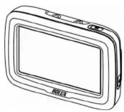
natural_image
Line drawing of a rectangular electronic device labeled 'HOLUX' (no additional text or symbols)
natural_image
Technical line drawing of a mechanical bracket component (no text or symbols)GPSmile 6430 Cradle
natural_image
Pure electrical circuit lines without any symbols
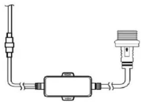
natural_image
Simple line drawing of a mechanical component with threaded shaft and pipe connection (no text or symbols)DC-DC Adapter Car Charger
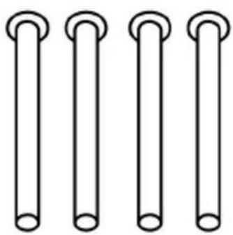
natural_image
Four identical cylindrical objects with circular ends, arranged horizontally (no text or symbols)
natural_image
Collection of mechanical parts including hex nuts and washers (no text or symbols)Screw kit (main accessory)
Motorbike RAM Mount Accessory (Optional)
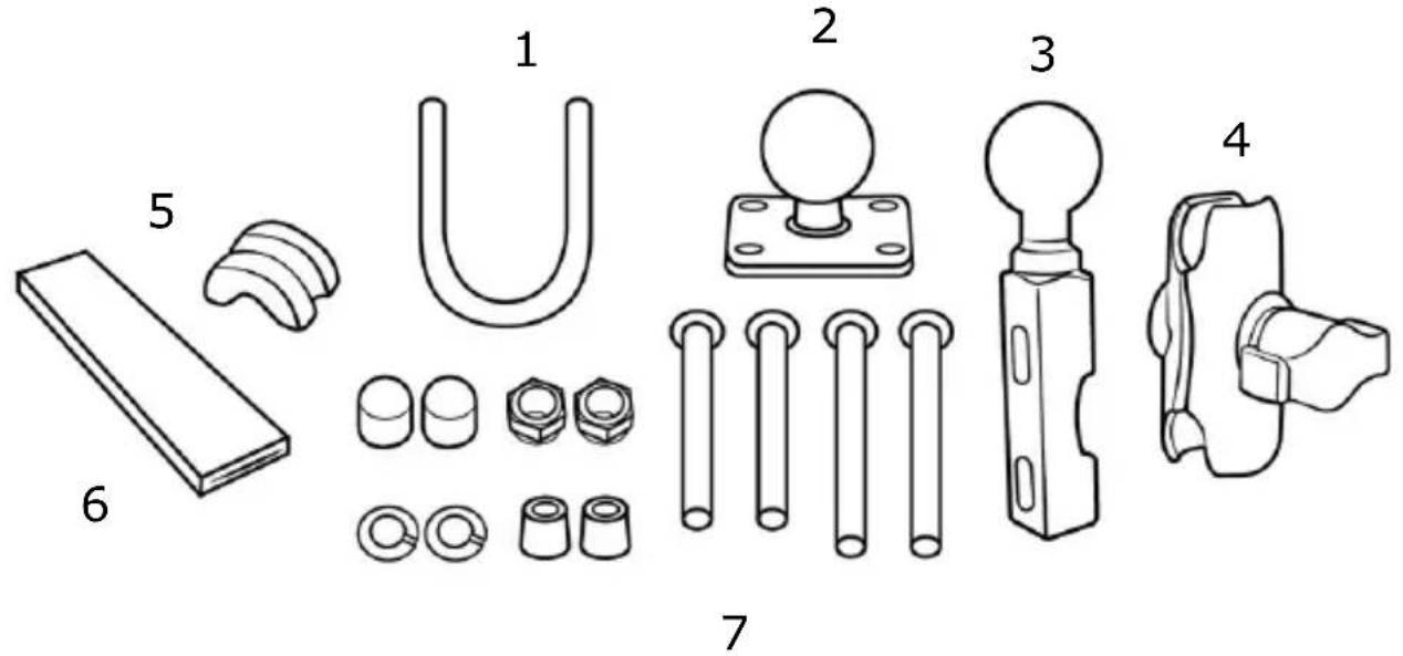
text_image
Technical diagram showing exploded view of mechanical components with numbered labels| 1. U-bolt Rail Mount 2. Device | Base Plate |
| 3. Motorcycle Handlebar Base | 4. Double Socket Arm |
| 5. Plastic Cushion 6. Square Rubber Neck | |
| 7. Screw kit (bolts, washers, spacers, nuts for motorbike RAM mount) | |
Optional accessory

natural_image
Line drawing of a medical or laboratory device with a bulb and curved arm (no text or symbols)Bluetooth headset
Basic Operation
Introduction
Front View
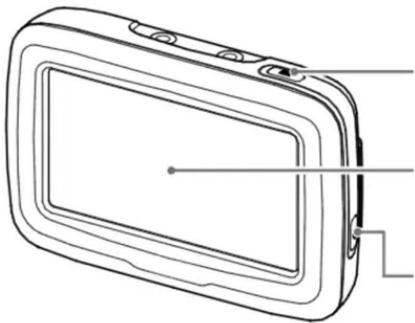
natural_image
Line drawing of a rectangular device with internal components and a small circular mark on the screen (no text or symbols)Main menu button
4.3" LCD touch screen
Power button
Rear View
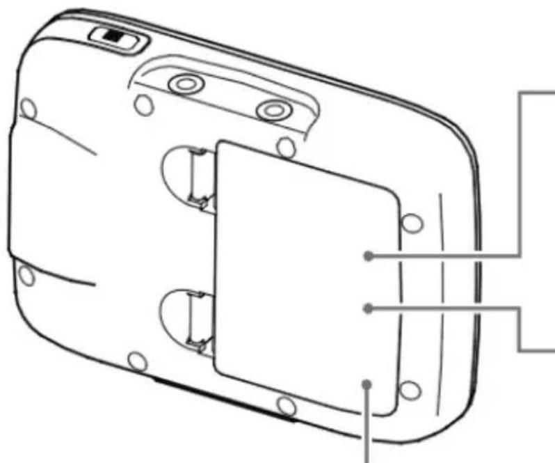
natural_image
Technical line drawing of a device casing with internal components and mounting holes (no text or symbols)Micro SD card slot (Under battery cover)
Mini-USB connector (Under battery cover)
Battery cover
Accessories
Cradle
I/O cap
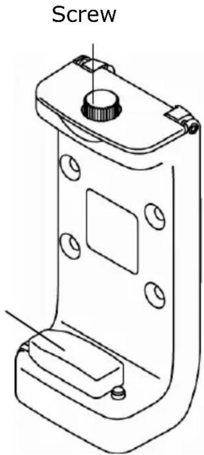
text_image
Screw
natural_image
Line drawing of a connector with two pins and a terminal block (no text or symbols)I/O interface
Getting Started
Install Cradle
| 1. Loosen the screw of cradle top. | 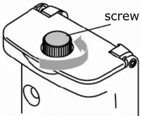 |
| 2. Open the cap of cradle top. | 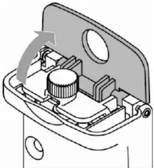 |
| 3. Open the I/O cap. | 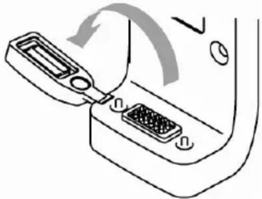 |
| 4. Insert the device concave into the cradle tabs.※ Please make sure the I/O pin is not wet or dirty. | 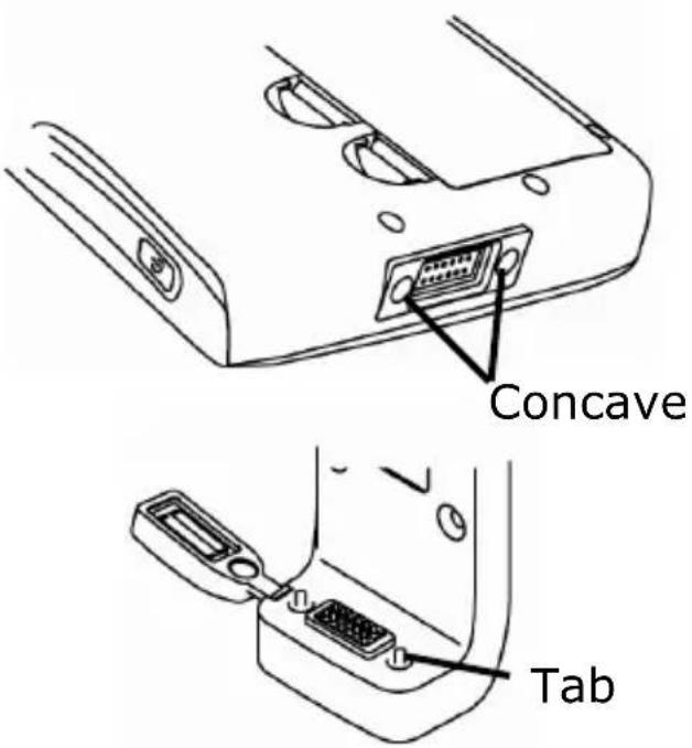 |
| 5. Slide the GPS into the cradle fitting holes to secure. |  |
| 6. Make sure the device is tightly fixed with the bracket, and gently close the cradle cap. | 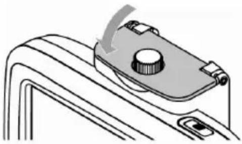 |
| 7. Tighten the screw. |  |
Remove Cradle
| 1. Loosen the screw of cradle top. |  |
| 2. Open the cradle cap and remove the device. |  |
| 3. Restore the I/O cap |  |
Install motorcycle RAM mount (Optional)
| 「A」Device Base Plate「B」Double Socket Arm「C」Motorcycle Handlebar Base | 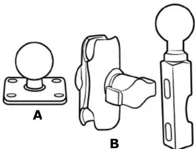 c c |
| Thread the bolts and nuts (screw kit of main accessory) to attach the 「A」 to cradle.Tighten the nuts to secure the 「A」. | 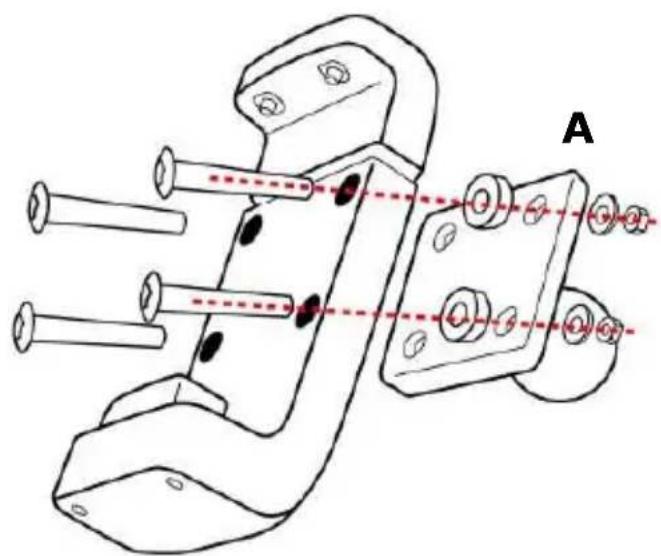 |
There are two solutions to install Motorcycle RAM mount: 「motorcycle handlebar」or「brake/clutch」.
Method 1: To install at handlebar with U-bolt
(1) 「U-bolt」slip into「Square rubber Neck」to protect the handlebar from scratching.

flowchart
graph TD
    A["Rectangular Block"] --> B["Step 1: Downward arrow"]
    B --> C["Step 2: Upward arrow"]
    C --> D["Step 3: Downward arrow"]
(2) Place the U-bolt around the handlebar, and thread the ends through the 「C」.
(3) To avoid slip, place 「plastic cushion」 between 「U-bolt」 and handlebar.
(4) Tighten the nuts to secure the base. Do not over tighten.

text_image
C
natural_image
Technical line drawing of a mechanical clamp or bracket assembly (no text or symbols)Method 2: To install at clutch/brake clamp bracket
(1) Remove the two factory bolts on your clutch/brake clamp bracket.
(2) Thread the new bolts (Screw kit of RAM mount) through the washers, 「C」, spacers, and clamp bracket.
(3) Tighten the bolts to secure the base.
※ There are long (QTY.2) and short (QTY.2) bolts in RAM mount screw kit, please select that you need to install.

natural_image
Technical line drawing of a mechanical assembly with rods and a handle (no text or symbols)After install the 「C」 at proper location, install other components.
| Attach the ball of the 「C」 with one side of 「B」. | 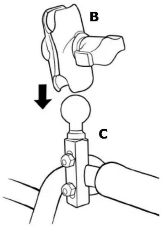 |
| Align the ball of the 「A」 with the other side of 「B」.Tighten the knob slightly. | 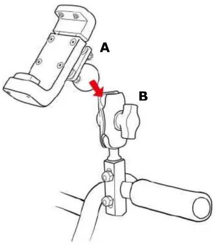 |
| (1) Adjust「A」and「C」for better viewing and operation.(2) Tighten the knob of「B」to secure the mount. | 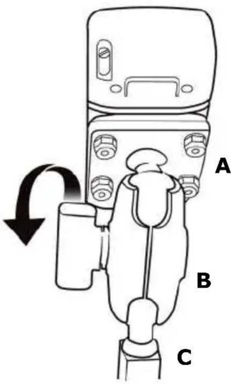 |
| For your riding safety, please loosen the knob of「B」to adjust the screen for better viewing and operation.After confirm the viewing, tighten the knob of「B」to secure the mount.Remind you: do not operate the device when you ride. |  |
※ Note:
Damage due to modifications, improper installation, road hazards or accident, are not covered. HOLUX does not liable for any injury, loss, or damage, direct or consequential, arising out of improper installation, or inability to use product.
Install/ Remove Battery
Please make sure the battery is installed before using the device.
| 1. Open the battery lid. | 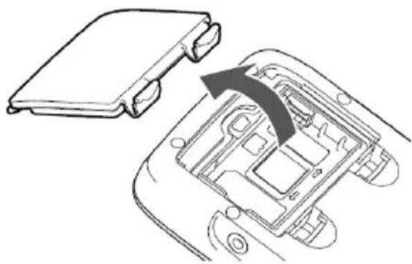 |
| 2. Install or Remove the battery. |   |
| 3. Restore the battery lid. |  |
Charging Battery
Connect the car charger or AC adapter to charging. The charging temperature for the product is between 0^ 45^ .
| 1. Open the battery lid. | 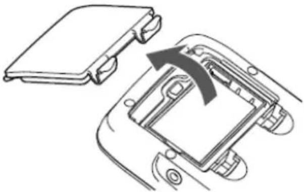 |
| 2. Connect the USB adapter to a wall outlet. | er
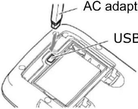
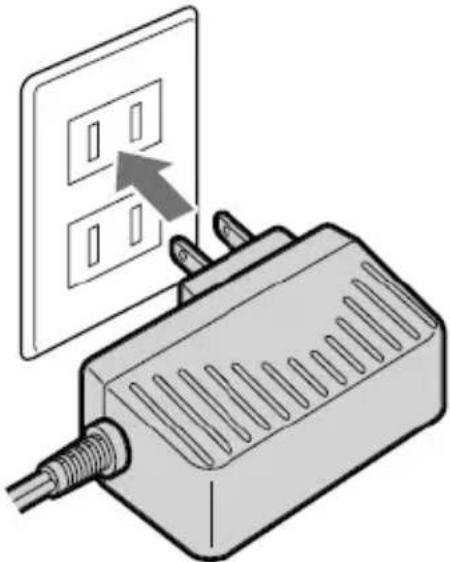 |
※ AC adapter (5V/2A) is an optional accessory.
Install SD Card (Optional)
| 1. Open the battery lid and remove the battery. |  |
| 2. Open SD card slot. | 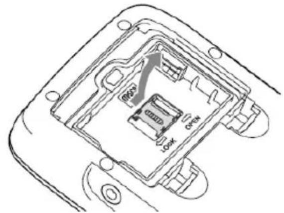 |
| 3. Insert SD card with its chip facing down and flat into the SD card slot. | 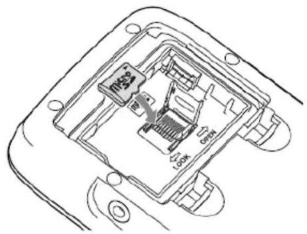 |
| 4. Push upward to lock the SD card slot. | 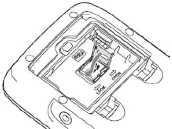 |
| 5. Put into the battery. | 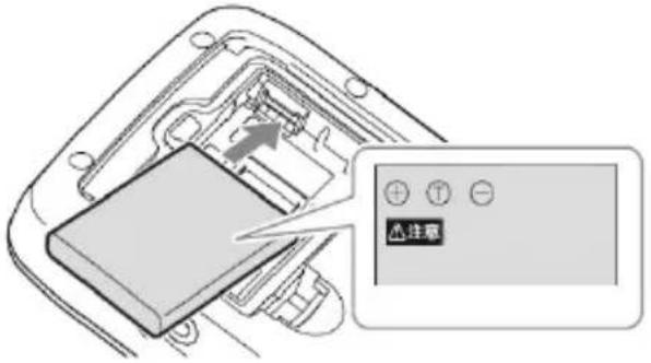 |
| 6. Restore the battery lid. |  |
Device connection Diagram

flowchart
graph TD
    A["GPSmile 61CS"] --> B["Car Charger"]
    A --> C["DC-DC Adapter (12V→5V)"]
※ Note:
Please connect DC-DC adapter to 「ACC ignition switching circuit」. Do not connect to positive/ negative electrode of battery directly to avoid exhaustion of battery power.
※ If you are unsure about attaching the mount kit or adapter yourself, ask a professional to fit it for you.
※ The user shall determine the suitability of the product for its intended use and connect. The user assumes all risk and liability, whatsoever, in connection with the mount. Damage due to modifications, improper installation, road hazards or accident, are not covered. HOLUX does not liable for any injury, loss, or damage, direct or consequential, arising out of improper installation, or inability to use product.
Operating Methods
Startup/ Shutdown
Please press and hold the power button for several seconds to turn on/ off the device.

text_image
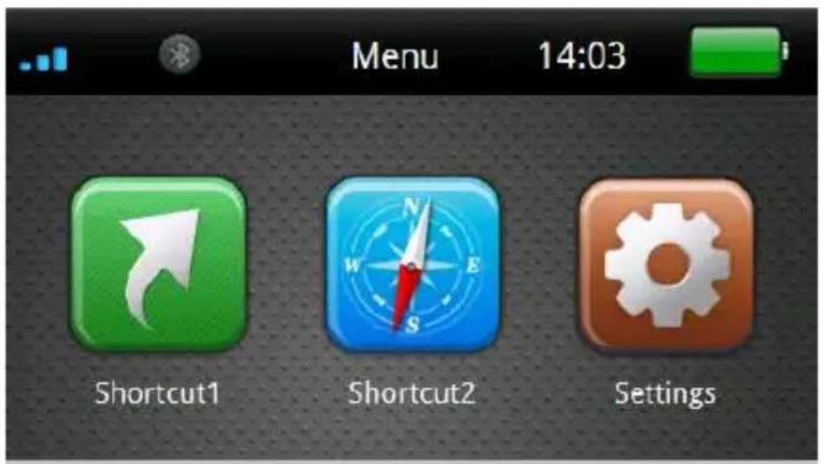
HOLUX ON/OFF Power buttonWhen the device is turned on, the screen will show the main screen consisting of three functions: Shortcut1, Shortcut2 and settings. Directly select an icon on the screen to use the function.

text_image
Menu 14:03 Shortcut1 Shortcut2 SettingsHot key
Press the [Hot key] to enter the [Brightness/ Volume] setup menu.
Click Button on the bottom-left corner screen to access Bluetooth setup menu.
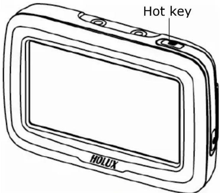
text_image
Hot key HOLUX
text_image
Brightness/Vol. 14:03 Volume BrightnessFor details, please refer to the [Brightness/Volume] and [Bluetooth] sections.
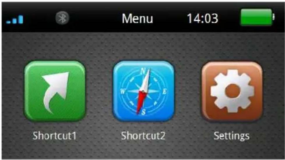
Battery Status
The icon displays the remaining battery power.
The icon means the battery power is lower than 15%, please charge the battery immediately.

text_image
Menu 14:03 Shortcut1 Shortcut2 Settings
text_image
Menu 14:04 Shortcut1 Shortcut2 Settings
text_image
Menu 14:04 Shortcut1 Shortcut2 SettingsFunction Menu
During the first startup, the screen will show the main screen consisting of three functions: Shortcut1, Shortcut2 and settings. Directly select an icon on the screen to use the function.
text_image
Menu 14:03 Shortcut1 Shortcut2 Settings| Shortcut1/ Shortcut2 | Drivers can set shortcuts on the main menu to a program that compatible with GPSmile 6430.※ For first setting, you can click the icon directly to enter「Setting」-「Shortcut」menu to setting.※ Notes:·GPSmile 6430 is only compatible with WinCE 6.0 programs.·Each 3rd party application has different settings of COM port and screen resolution. Therefore, Holux does not guarantee the compatibility of each program. |
| Settings System setup include: Brightness/Volume, Time/Language, Bluetooth and System. | |
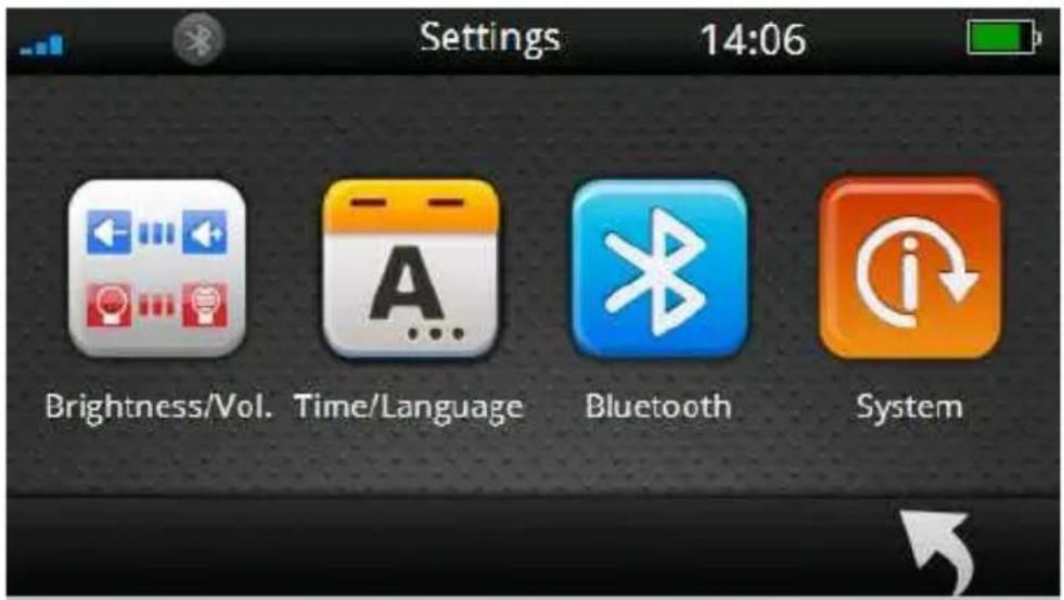
Settings
After starting up the system, select the [Settings] button to enter.
text_image
Menu 14:03 Shortcut1 Shortcut2 Settings
text_image
Settings 14:06 Brightness/Vol. Time/Language Bluetooth SystemThe settings menu appears as shown above. The following sections describe these buttons and functions.
You can customize the device settings such as brightness/volume, Time/Language, Bluetooth, and System.
Brightness/ Volume
Click [Brightness/volume] button to access Brightness/volume setup menu.

text_image
Settings 14:06 Brightness/Vol. Time/Language Bluetooth System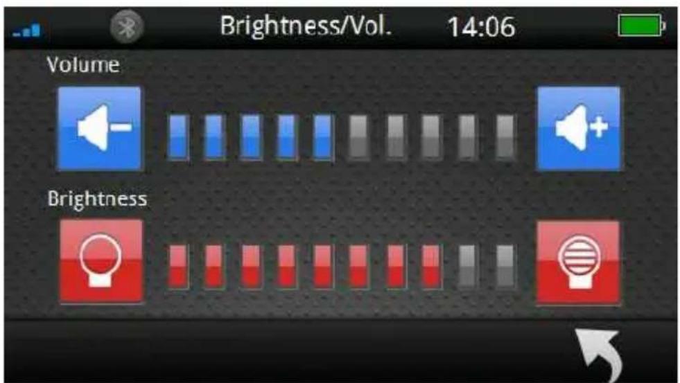
text_image
Brightness/Vol. 14:06 Volume Brightness
Select button to increase/decrease brightness. There are ten levels.
Select button to adjust volume. There are ten levels.
Click a button to go back to the previous page.
※Tip: Press the [Hot key] on the top of the device to quickly access [Brightness/ Volume] setup menu.

text_image
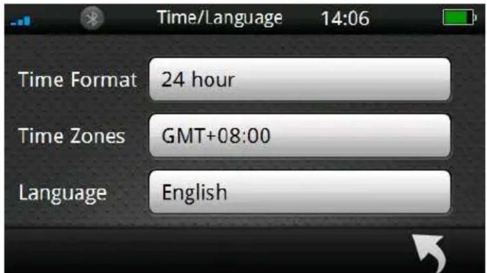
Brightness/Vol. 14:03 Volume BrightnessTime/ Language
Click [Time/Language] button to access Time/Language setup menu.

text_image
Settings 14:06 Brightness/Vol. Time/Language Bluetooth System
text_image
Time/Language 14:06 Time Format 24 hour Time Zones GMT+08:00 Language EnglishTime Format
Select [Time Format] 24 hour to enter time format setup menu.

text_image
Time/Language 14:06 Time Format 24 hour Time Zones GMT+08:00 Language English
text_image
Time Format 14:07 12 hour 24 hourSelect preferred time format from the menu.
Click Button to go back to the previous page.
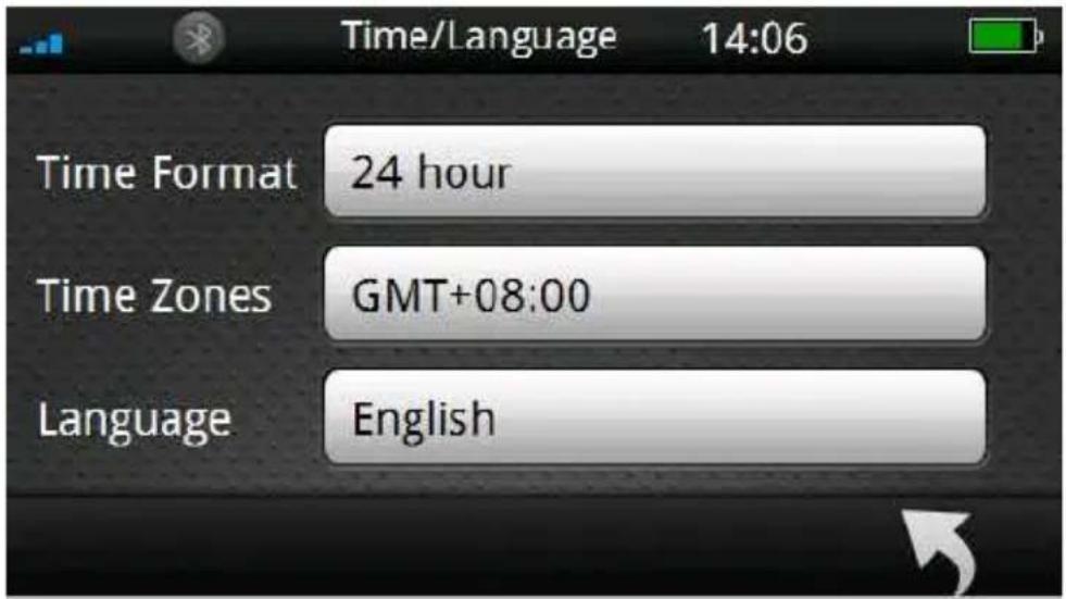
Time Zone
Select [Time Zone] to enter time zone setup menu.
text_image
Time/Language 14:06 Time Format 24 hour Time Zones GMT+08:00 Language English
text_image
GMT+08:00(Kuala Lumpur, Singapore) GMT+08:00(Taipei) GMT+08:00(Perth)Select ▲ ▼ button to choose the correct time zone.
Click a button to go back to the previous page.
Language
Select [Language] English to enter language setup menu.
text_image
Time/Language 14:06 Time Format 24 hour Time Zones GMT+08:00 Language English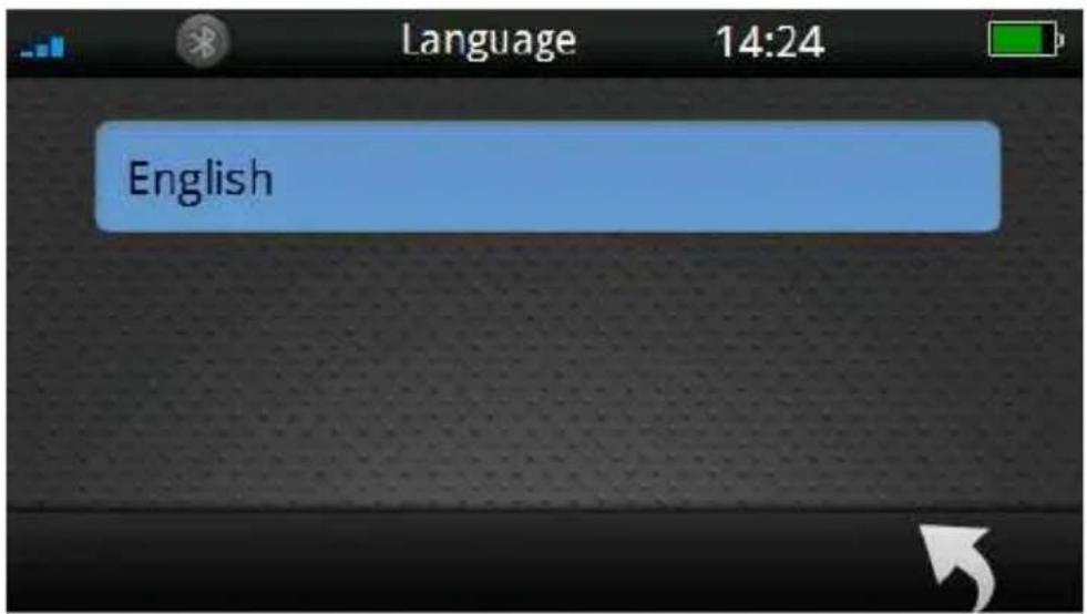
text_image
Language 14:24 EnglishSelect preferred language from the menu.
Click a button to go back to the previous page.
Bluetooth
Click [Bluetooth] button to access Bluetooth setup menu.
text_image
Settings 14:06 Brightness/Vol. Time/Language Bluetooth System
text_image
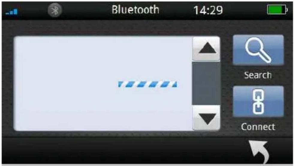
Bluetooth 14:24 Search ConnectClick button to search bluetooth devices.
The graphic shown below indicating the Bluetooth is searching new devices.
text_image
Bluetooth 14:29 Search ConnectDuring the Bluetooth searching process, users can cancel the process by click a button.
Press the button and a message appears on the screen; press the button to exit the search, or press the

button to continue searching.

text_image
Bluetooth 14:24 Abort? ConnectAfter completed the scanning process, GPSmile 6430 will display a list of scanned devices.
Select the particular Bluetooth device from the list, and click the "Connect" button to enable the function.

text_image
DRC-BT30 MM5002-1EB101 Bluetooth 14:40 Search Connect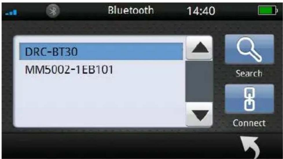
text_image
Bluetooth 14:40 DRC-BT30 MM5002-1EB101 Search Connect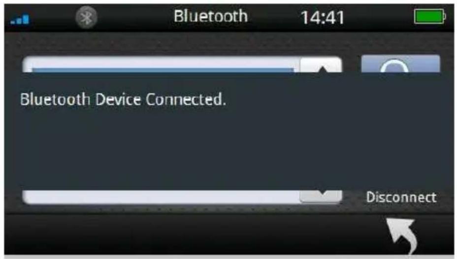
text_image
Bluetooth 14:41 Bluetooth Device Connected. Disconnect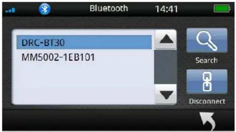
text_image
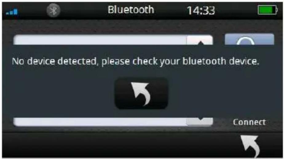
Bluetooth 14:41 DRC-BT30 MM5002-1EB101 Search DisconnectWhen no devices were found during the scanning process, the following message will be shown on screen.
text_image
Bluetooth 14:33 No device detected, please check your bluetooth device. ConnectClick 📄 button to go back and retry the Bluetooth scanning process again.
System setup
Click [System] button to access system setup menu.

text_image
Settings 14:06 Brightness/Vol. Time/Language Bluetooth System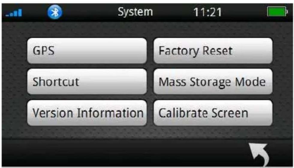
text_image
GPS Shortcut Version Information Factory Reset Mass Storage Mode Calibrate Screen System 11:21In system setup menu, the items contain [GPS]、[Factory Reset]、[Shortcut]、[Mass Storage Mode]、[Version Information] and [Calibrate Screen].
The followings describe these buttons and functions.
GPS
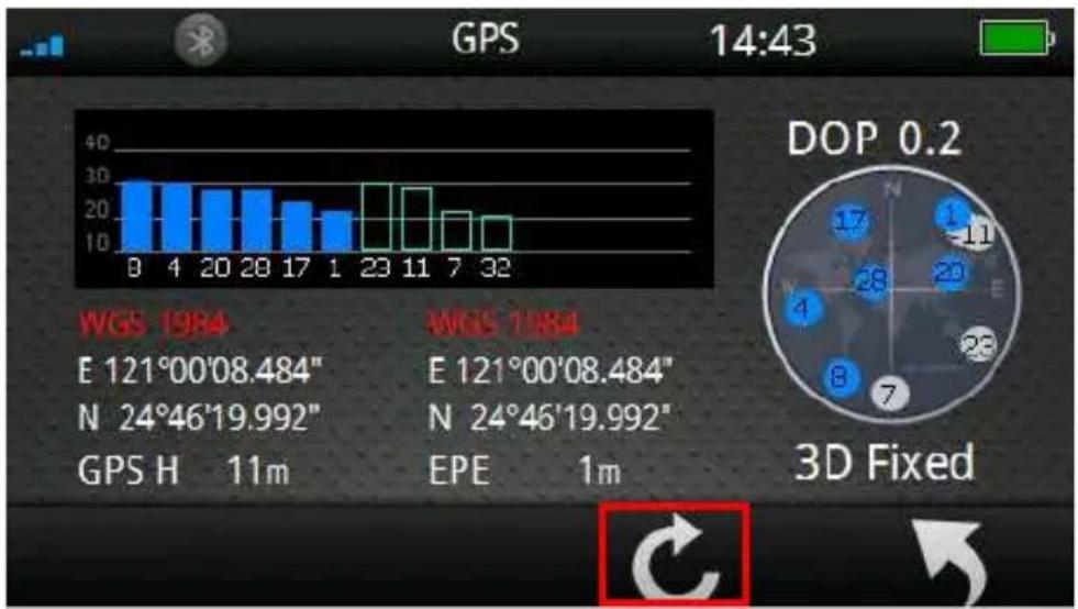
Select [GPS] button to enter satellite status page.

text_image
System 11:21 GPS Factory Reset Shortcut Mass Storage Mode Version Information Calibrate Screen Satellite signal strength GPS 14:43 Positioning precision Satellite number 3D Fixed GPS measured Height GPS Estimated Position Error DOP 0.2 E 121°00'08.484" N 24°46'19.992" GPS H 11m EPE 1m※ When searching satellite signal, GPSmile 6430 will display「Acquiring」. When「3D fixed」is displayed, 61CS has fully acquired the GPS signal and is ready for use.
Reset GPS
Click button to reset GPS.
bar
| GPS | Value | |---|---| | 0 | 28 | | 4 | 27 | | 20 | 25 | | 28 | 25 | | 17 | 22 | | 1 | 19 | | 23 | 28 | | 11 | 26 | | 7 | 19 | | 32 | 17 | DOP 0.2 E 121°00'08.484" N 24°46'19.992" GPS H 11m WGS 1984 WGS 1984 E 121°00'08.484" N 24°46'19.992" EPE 1m 3D Fixed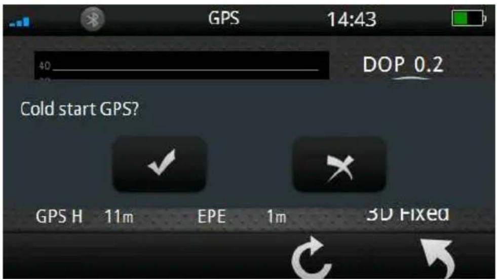
text_image
GPS 14:43 40_ DOP 0.2 Cold start GPS? GPS H 11m EPE 1m 3D FixedClick Button to go back to the previous page.
Note: When the device is not in use for more than 3 days, reset GPS will allow 61CS to acquire the GPS signal much faster!
Factory Reset
Select [Factory Reset] to restore the factory default settings.
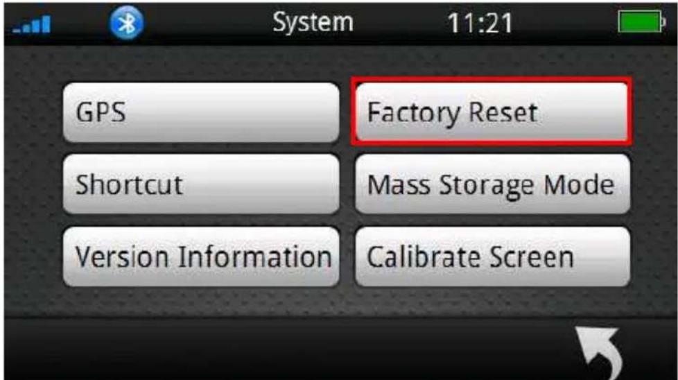
text_image
GPS Factory Reset Shortcut Mass Storage Mode Version Information Calibrate Screen System 11:21
text_image
System 14:44 All your settings will be restored to factory defaults! Are you sure?Click button to restore to factory defaults.
Click a button to go back to the previous page.
※ Note: once the device is reset to factory defaults, all settings you set will be erased.
Shortcut
Select [Shortcut] to access shortcut setup menu.

text_image
GPS Shortcut Factory Reset Mass Storage Mode Version Information Calibrate Screen System 11:21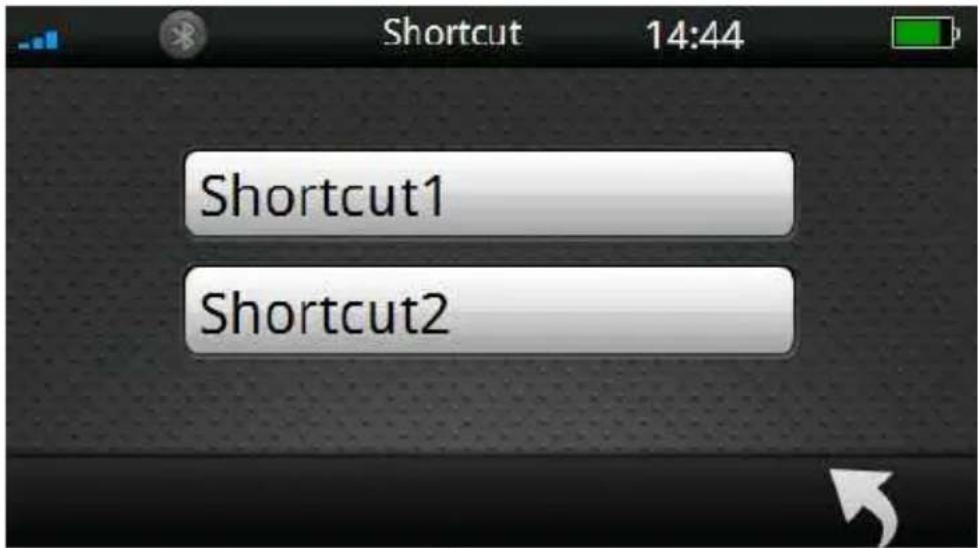
text_image
Shortcut 14:44 Shortcut1 Shortcut2To set shortcuts on main menu to a program, please see the example below on how to select the shortcuts.
To set the shortcut1:
Step1.
Click [Shortcut1] icon to enter shortcut1 setup menu.
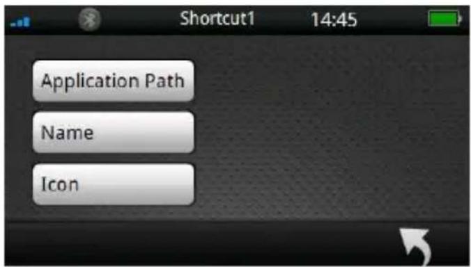
On the shortcut1 page, set [Application Path], [Name] and [Icon].

text_image
Shortcut 14:44 Shortcut1 Shortcut2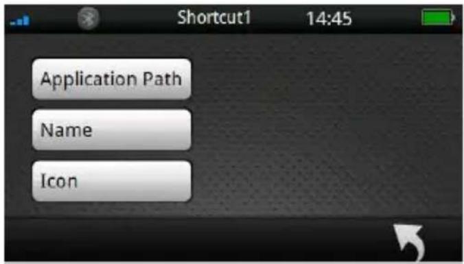
text_image
Shortcut1 14:45 Application Path Name IconStep2.
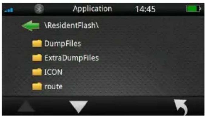
Click [Application Path] to enter folder list page.
text_image
Shortcut1 14:45 Application Path Name IconSelect button to choose the correct folder icon.
Click the .exe file in folders directly to specify the program as the shortcut.
text_image
Application 14:45 \ResidentFlash\ DumpFiles ExtraDumpFiles ICON routeClick 📄 button to go back to the previous page.

Note:
If you store the application program in "Resident Flash" and "SD card"; click [Application Page] icon, the page will display "Resident Flash" and "SDMMC (SD card)" two folders.
※ How to place files in SD card:
(1) Create a folder in SD card.
(2) Store the program in the folder.
(3) Click the .exe file of the program on storage location.
\ResidentFlash= Internal memory \SDMMC= SD card

text_image
Application 14:45 ResidentFlash SDMMC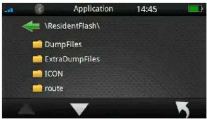
text_image
Application 14:45 \ResidentFlash\ DumpFiles ExtraDumpFiles ICON routeStep3.
Click [Name] to enter input title menu.
Use digital keypad on the screen to input the title name. You can input English (uppercase/ lowercase), number and symbol. After input value,
click to save the value and return.
Click button to go back to the previous page.

text_image
Application Path Name Icon \ResidentFlash\Navi\Holuxnavi.exe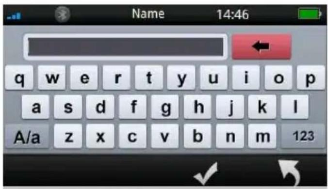
text_image
Name 14:46 q w e r t y u i o p a s d f g h j k l A/a z x c v b n m 123Step4.
Click [Icon] to enter the icon list menu.
Select


button to switch the icon list page, and click the icon to setup directly.
Click

tton to go back to the previous page.
text_image
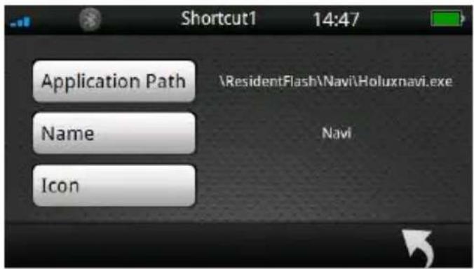
Shortcut1 14:47 Application Path \ResidentFlash\Navi\Holuxnavi.exe Name Navi Icon
text_image
Icon 14:47Step5.
After input [Application Path], [Name] and
[Icon], click the setting.

save
The shortcut that you set will be displayed on the main menu.

text_image
Shortcut1 14:47 Application Path Name Icon \ResidentFlash\Navi\Holuxnavi.exe Navi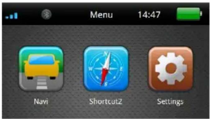
text_image
Menu 14:47 Navi Shortcut2 SettingsMass Storage Mode
Select enter [Mass Storage Mode] and connect device to a computer, SD card files are now accessible from the connected PC.

text_image
GPS Shortcut Version Information Factory Reset Mass Storage Mode Calibrate Screen 11:21 SystemThe page below indicates the device not yet connected to a PC.

text_image
Please connect to a computer via USB.The page below indicated the device is now connected to a PC.
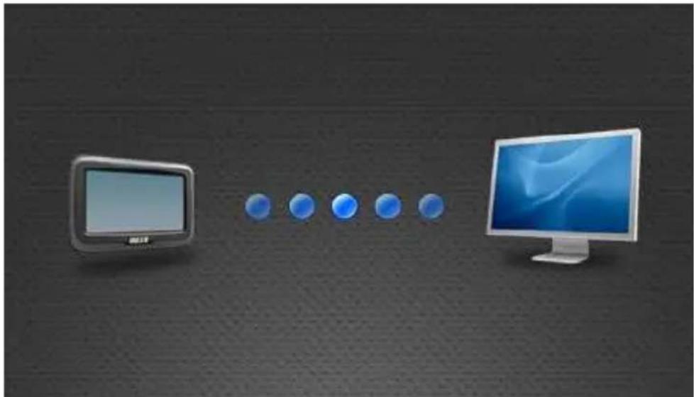
natural_image
Illustration of a desktop computer monitor connected to five blue circular icons on a dark textured background (no text or symbols)Version Information
The screen displays the OS and AP version information.

text_image
GPS Shortcut Version Information Factory Reset Mass Storage Mode Calibrate Screen System 11:21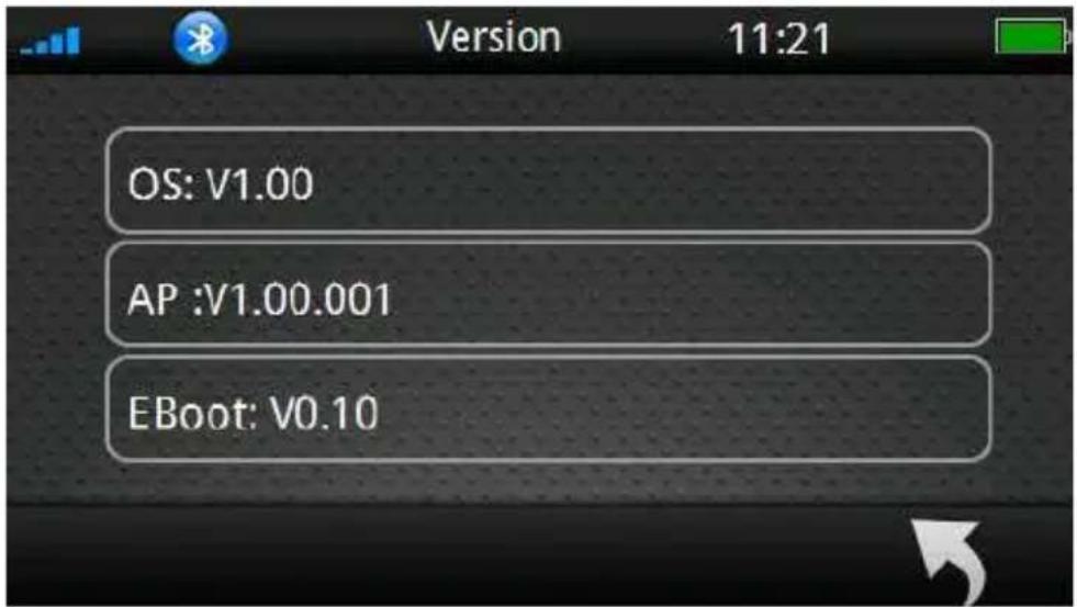
text_image
Version 11:21 OS: V1.00 AP :V1.00.001 EBoot: V0.10Calibrate Screen
Select [Calibrate Screen] to start the screen calibration procedure.

text_image
GPS Shortcut Version Information Factory Reset Mass Storage Mode Calibrate Screen 11:21 SystemUse the finger/stylus and touch the cross at the center of the screen. Continue the calibration by touching the cross. The system setting page will return when adjustment is finished.

text_image
Carefully press and briefly hold stylus on the center of the target. Repeat as the target moves around the screen.Warranty Statement
- This warranty applies to parts and services that are manufactured and sold through Holux Technology Inc. The local area covered is Taiwan; the warranty length is one year from date of purchase (starting from the date on the sales receipt). Under normal user operation, Holux Technology provides free repair services.
✿ After repair, the replaced parts are the properties of Holux Technology Inc.
- Holux Technology is not responsible for providing repairs or replacements of any software; Holux Technology does not provide any warranty service for third party software/hardware.
- Important instructions
Note: This warranty does not cover damage or malfunction from the below causes: unauthorized disassembly/modification of unit, abuse or incorrect usage, accidental and other unpreventable causes, operation under variables mentioned that are different from those in this product user manual, using parts not made or sold by Holux Technology, or repairs done by anyone other than Holux Technology and authorized retail/service providers.
◆ Expendable parts are not covered in the warranty.
- Holux Technology is not responsible for any program, data, or portable storage media damages or loss. Please contact your local Holux Technology authorized service provider to learn more about geographical limitations, proof of purchase requests, response time agreements, and other specific maintenance service requests.
Technical Support
- If there are any questions regarding the use of this product, please log on to the website www.holux.com and see the FAQ.
Maintenance Service
HOLUX Technology, Inc.
+886-3-6687000
website: www.holux.com
FAQ: FAQ.holux.com
or
Contact your nearest dealer, for further support.
HOLUX Technology, Inc.
www.holux.com
Federal Regulations
This device complies with Part 15 of the FCC rules.
Operation is subject to the following two conditions: (1) This device may not cause harmful interference, and (2) this device must accept any interference received, including interference that may cause undesired operation.
FEDERAL COMMUNICATIONS COMMISSION INTERFERENCE STATEMENT
This equipment has been tested and found to comply with the limits for a Class B digital device, pursuant to Part 15 of the FCC Rules. These limits are designed to provide reasonable protection against harmful interference in a residential installation. This equipment generates uses and can radiate radio frequency energy and, if not installed and used in accordance with the instructions, may cause harmful interference to radio communications. However, there is no guarantee that interference will not occur in a particular installation. If this equipment does cause harmful interference to radio or television reception, which can be determined by turning the equipment off and on, the user is encouraged to try to correct the interference by one or more of the following measures:
- Reorient or relocate the receiving antenna.
- Increase the separation between the equipment and receiver.
- Connect the equipment into an outlet on a circuit different from that to which the receiver is connected.
- Consult the dealer or an experienced radio/TV technician for help.
CAUTION:
Any changes or modifications not expressly approved by the
grantee of this device could void the user's authority to operate this equipment.
RF Exposure Warning
This equipment must be installed and operated in accordance with provided instructions and the antenna(s) used for this transmitter must be installed to provide a separation distance of at least 20 cm from all persons and must not be co-located or operated in conjunction with any other antenna or transmitter. End-users and installers must be provided with antenna installation instructions and transmitter operating conditions for satisfying RF exposure compliance.