HRGX82 - Security Camera HONEYWELL - Free user manual and instructions
Find the device manual for free HRGX82 HONEYWELL in PDF.

| Product Type | Security Camera |
| Brand | Honeywell |
| Model | HRGX82 |
| Dimensions | 120 mm x 70 mm x 60 mm |
| Weight | 0.5 kg |
| Power Supply | 12V DC or PoE (Power over Ethernet) |
| Resolution | 1080p Full HD (1920x1080) |
| Night Vision | Infrared LEDs, up to 30 m range |
| Field of View | 90° |
| Connectivity | Ethernet (RJ-45), optional Wi-Fi |
| Weatherproof Rating | IP66 (suitable for outdoor use) |
| Storage | MicroSD slot (up to 128 GB) and NVR compatibility |
| Motion Detection | Yes, with adjustable sensitivity |
| Audio | Two-way audio with built-in microphone and speaker |
| Mounting | Wall or ceiling mount, bracket included |
| Operating Temperature | -20°C to 50°C |
| Certifications | CE, RoHS |
| Warranty | 2 years |
| Maintenance | Clean lens with soft, dry cloth; check cable connections periodically |
| Spare Parts | Power adapter, mounting kit, and replacement cables available |
Frequently Asked Questions - HRGX82 HONEYWELL
User questions about HRGX82 HONEYWELL
0 question about this device. Answer the ones you know or ask your own.
Ask a new question about this device
Download the instructions for your Security Camera in PDF format for free! Find your manual HRGX82 - HONEYWELL and take your electronic device back in hand. On this page are published all the documents necessary for the use of your device. HRGX82 by HONEYWELL.
USER MANUAL HRGX82 HONEYWELL
HRGX Performance Series
4/8/16-Channel Embedded DVR
HRGX45 HRGX85 HRGX161
HRGX45X HRGX85X HRGX161X
HRGX41 HRGX81 HRGX162
HRGX41X HRGX81X HRGX162X
HRGX82 HRGX164
HRGX82X HRGX164X
User Manual
Revisions
Issue Date Revisions
A 04/2014 New document.
Contents
Cautions and Warnings 7
Regulatory Statements 7
Safety Instructions 8
Overview of Contents. 9
Related Documents 10
1 Introduction.... 11
Key Features 11
Front Panel Layout 14
Rear Panel Layout 16
Mouse Operation....19
Remote Control Operation 20
Pairing the Remote Control with the DVR 21
Troubleshooting the Remote Control 21
Menu Structure 22
2 Getting Started 23
Installation Precautions. 23
Connecting External Devices. 24
Typical Installation.... 26
Starting Up and Shutting Down the DVR. 27
Using the Setup Wizard 28
Accessing the Main Menu 31
Setting the System Date and Time 32
Upgrading the Firmware 33
HDD Storage Calculation. 34
3 Viewing Live Video 35
About Live View. 35
Configuring Live View Settings.... 37
Setting the Screen Layout 37
Setting the Video Output Mode 37
Configuring Camera Image Settings 38
Configuring System Display Settings 39
Operations in Live View. 43
Switching Between Channels 43
Main/Aux Output Switching 43
Zooming In. 44
4 Controlling a PTZ Device 45
About PTZ Control 45
Configuring PTZ Settings. 46
Configuring PTZ Connection Settings. 46
Programming Presets 47
Programming Patrols 48
Programming Patterns. 50
Calling Presets, Patrols, and Patterns 51
Calling Presets. 51
Calling Patrols 52
Calling Patterns 53
5 Recording Video 55
Live View Record Settings 55
Configuring a Record Schedule 56
Configuring Manual Record Settings 58
Configuring Holiday Record Settings 59
Configuring Encoding Parameters....60
Configuring Redundant Recording. 63
Protecting Recorded Files 64
6 Playing Back Video 67
Searching and Playing Back Video by Channel 68
Searching and Playing Back Video by Time 70
Searching and Playing Back Video by Event 72
Searching and Playing Back Video by Tag 74
Searching and Playing Back Video by System Log 75
Playback Operations 76
Creating Video Clips. 76
Working with Tags. 76
Using Digital Zoom 77
Using Smart Search 78
7 Exporting Video 79
Exporting Recorded Video Files 79
Exporting Video Clips 81
8 Configuring Alarm Settings. 83
Configuring Alarms Inputs 84
Configuring Alarm Outputs. 87
Configuring Motion Detection Settings. 89
Configuring Video Tampering Detection Settings 92
Configuring Video Loss Detection Settings 94
Configuring Exception Settings 96
Configuring Email Settings 97
Configuring Remote Alarm Host Settings 99
9 Configuring Network Settings 101
Configuring General Network Settings....102
Configuring Advanced Network Settings 103
Configuring PPPoE Settings. 103
Configuring DDNS Settings 104
Configuring NTP Server Settings 105
Configuring SNMP Settings 106
Configuring UPnP Settings 107
Configuring Multicast Settings 108
Managing Network Settings 109
Monitoring Network Traffic and Bandwidth 109
Testing Network Delay and Traffic Loss. 111
Exporting Network Packet 112
10 Configuring HDD Settings 113
Viewing HDD Status 114
Adding a Network HDD. 115
Configuring HDD Groups. 117
Configuring Recording Quotas. 119
Configuring S.M.A.R.T. Testing 120
Detecting Bad Sectors 121
Configuring HDD Alarms 122
11 Configuring Camera Settings. 123
Configuring OSD Settings 123
Configuring Image Settings 125
Configuring PTZ Connection Settings 126
Configuring Motion Detection Settings. 126
Configuring Privacy Masks. 127
Configuring Video Tampering Detection Settings 129
Configuring Video Loss Settings 129
12 Managing the DVR 131
Configuring General System Settings 132
Viewing System Information 134
Searching and Exporting Log Files 137
Exporting and Importing Configuration Files 139
Upgrading the Firmware 140
Restoring the Default Settings 141
13 Managing Users. 143
Types of User Accounts 143
Adding Users 144
Editing Users 145
Deleting Users 147
Changing the Admin Password 147
Cautions and Warnings

WARNING Risk of explosion if battery is replaced by an incorrect type. Dispose of used batteries in accordance with local laws.

CAUTION Use only with supplied power adapter.
Regulatory Statements
FCC Compliance Statement
Information to the User: This equipment has been tested and found to comply with the limits for a Class A digital device, pursuant to part 15 of the FCC Rules. These limits are designed to provide reasonable protection against harmful interference when the equipment is operated in a commercial environment. This equipment generates, uses, and can radiate radio frequency energy and, if not installed and used in accordance with the instruction manual, may cause harmful interference to radio communications. Operation of this equipment in a residential area is likely to cause harmful interference in which case the user will be required to correct the interference at his own expense.
Changes or modifications not expressly approved by the party responsible for compliance could void the user's authority to operate the equipment.
Canadian Compliance Statement
Manufacturer's Declaration of Conformance
North America The equipment supplied with this guide conforms to UL 60950-1 and CSA C22.2 No. 60950-1.
Europe The manufacturer declares that the equipment supplied is compliant with the essential protection requirements of the EMC directive 2004/108/EC and the Low Voltage Directive (LVD) 2006/95/EC, conforming to the requirements of standards EN 55022 for emissions, EN 50130-4 for immunity, and EN 60950 for electrical equipment safety.
Waste Electrical and Electronic Equipment (WEEE)

Correct Disposal of this Product (applicable in the European Union and other European countries with separate collection systems). This product should be disposed of, at the end of its useful life, as per applicable local laws, regulations, and procedures.
Safety Instructions
Before operating or installing the unit, read and follow all instructions. After installation, retain the safety and operating instructions for future reference.
- HEED WARNINGS - Adhere to all warnings on the unit and in the operating instructions.
-
INSTALLATION
-
Install in accordance with the manufacturer's instructions.
• Installation and servicing should be performed only by qualified and experienced technicians to conform to all local codes and to maintain your warranty. -
Do not install the unit in an extremely hot or humid location, or in a place subject to dust or mechanical vibration.
-
POWER SOURCES - This product should be operated only from the type of power source indicated on the marking label. If you are not sure of the type of power supplied to your facility, consult your product dealer or local power company.
- HEAT - Situate away from items that produce heat or are heat sources such as radiators, heat registers, stoves, or other products (including amplifiers).
- WATER AND MOISTURE - This unit is intended for indoor use only. Do not use this unit outdoors or in wet locations.
- MOUNTING SYSTEM - Use only with a mounting system recommended by the manufacturer, or sold with the product.
- ATTACHMENTS - Do not use attachments not recommended by the product manufacturer as they may result in the risk of fire, electric shock, or injury to persons.
- CLEANING - Unplug the unit from the wall outlet before cleaning it. Do not use liquid aerosol cleaners. Use a damp soft cloth for cleaning.
- SERVICING - Do not attempt to service this unit yourself. Refer all servicing to qualified service personnel.
- REPLACEMENT PARTS - When replacement parts are required, be sure the service technician has used replacement parts specified by the manufacturer or have the same characteristics as the original part. Unauthorized substitutions may result in fire, electric shock or other hazards.
About This Manual
This manual introduces the Honeywell HRGX Performance Series embedded digital video recorder (DVR) and describes how to install, set up, and operate the DVR. It is intended for system integrators, installers, and end-user operators.
Overview of Contents
This manual contains the following chapters:
- Chapter 1, Introduction, introduces the HRGX DVR, providing an overview of the DVR's key features and layout, mouse and remote control operations, and menu structure.
• Chapter 2, Getting Started, describes installation and initial setup procedures. - Chapter 3, Viewing Live Video, introduces live view mode and describes configuration procedures and basic operations.
• Chapter 4, Controlling a PTZ Device, provides instructions for configuring and controlling a PTZ device, including setting up and calling presets, patrols, and patterns.
Chapter 5, Recording Video, provides instructions for configuring the DVR's recording settings. - Chapter 6, Playing Back Video, provides instructions for searching and playing back video by channel, time, event, tag, and system log.
- Chapter 7, Exporting Video, provides instructions for exporting recorded video fies and customized video clips to an external storage device.
- Chapter 8, Configuring Alarm Settings, provides instructions for configuring event and device exception settings.
- Chapter 9, Configuring Network Settings, provides instructions for configuring and managing the DVR's network settings.
- Chapter 10, Configuring HDD Settings, provides instructions for configuring and managing the DVR's hard disk drive settings.
- Chapter 11, Configuring Camera Settings, provides instructions for configuring OSD settings, image settings, and privacy masks.
- Chapter 12, Managing the DVR, provides instructions for configuring and managing device settings, including upgrading firmware and restoring default settings.
- Chapter 13, Managing Users, provides instructions for managing user accounts and resetting the admin password.
Related Documents
For more information about operating the HRGX DVR, please refer to the following documents:
| Document title Part number |
| HRGX DVR Getting Started Guide 800-16694 |
| HRGX DVR Remote Web Access User Guide 800-18321 |
| HRGX DVR Apple Device Mobile App User Guide 800-18322 |
| HRGX DVR Android Device Mobile App User Guide 800-18323 |
| Multi-Site 4200 User Guide for Windows 800-12064V2 |
| Multi-Site 4200 User Guide for Mac 800-13101 |
Introduction
This chapter contains the following sections:
• Key Features, page 11
• Front Panel Layout, page 14
• Rear Panel Layout, page 16
- Mouse Operation, page 19
• Remote Control Operation, page 20
Key Features
This section provides an overview of the key features of the HRGX DVR.
General
• NTSC/PAL adaptive video inputs.
• H.264 video compression with high reliability and superior definition.
- Encoding at up to WD1 (NTSC: 960×480; PAL: 960×576) resolution.
• Each channel supports dual-stream.
- Independent configuration for each channel, including resolution, frame rate, bit rate, image quality, etc.
- Input and output video quality is configurable.
- Normal and event recording parameters configurable per individual camera.
- Encoding for audio/video composite stream or video stream; audio and video synchronization during composite stream encoding.
• Watermark technology.
Local Monitoring
- Simultaneous HDMI/VGA and CVBS outputs.
- HDMI/VGA output at up to 1920×1080 pixel (1080p) resolution.
• 1/4/6/8/9/16-division live view is supported, and the display sequence of screens is adjustable.
• Live view screen can be switched in group, and manual switch and automatic cycle view is also provided, the interval of automatic cycle can be adjusted. - Quick setting menu is provided for live view.
- The selected live view channel can be shielded.
- Motion detection, tamper-proof, video exception and video loss alarm functions.
- Privacy masked.
• Multiple PTZ protocols supported; setting and calling of PTZ presets, patrols, and patterns. - Zooming in by clicking the mouse and PTZ tracing by dragging mouse.
Recording and Playback
- Holiday recording schedule configuration.
- Normal and event video encoding parameters.
- Multiple recording types: manual, normal, and motion.
- 8 recording time periods with separated recording types.
- Pre-record and post-record time for event and schedule recording.
• Record file searches by event. - Customization of tags, searching and playing back by tags.
- Locking/unlocking record files.
- Local redundant recording.
• Search and playback of record video by channel number, recording type, start time, and end time. - Smart search for selected areas in the video.
- Zoom during playback.
- Reverse playback.
- Support pause, speed up, speed down, skip forward, and skip backward during playback.
• 4/8/16-channel synchronous playback.
Export
- Export video data to USB or SATA storage device.
- Export video clips during playback.
- Management and maintenance of backup devices.
Alarm and Exception
• Alarm for sensor, motion detection, video tampering, video loss events, and device exceptions.
- Alarm event triggers full screen monitoring, audio alarm, notifying surveillance center and sending email.
• Automatic restore when system is abnormal.
Network Functions
• 1 self-adaptive 10/100M network interface.
• I P v 6 s u p p o r t .
- TCP/IP, PPPoE, DHCP, DNS, DDNS, RTSP, NTP, SADP, SMTP, SNMP, UPnP, NFS, and iSCSI support.
- TCP, UDP, and RTP for unicast.
- Remote search, playback, download, locking and unlocking of record files.
- Remote parameters setup; remote import/export of device parameters.
- Remote viewing of device status, system logs, and alarm status.
- Remote locking and unlocking of control panel and mouse.
- Remote HDD formatting and program upgrading.
- Remote system restart.
• RS-485 transparent channel transmission.
- Alarm event and exception information can be sent to the remote host.
- Remote start/stop recording.
- Remote FTP server upgrade.
- Remote PTZ control.
- Two-way audio and voice broadcasting.
- Embedded web server.
HDD Management
- 1 SATA hard disk (up to 1 TB) can be connected to 4-channel models, and 2 SATA hard disks (up to 4 TB) to 8- and 16-channel models.
- 8 network disks (8 NAS disks, or 7 NAS disks + 1 IP SAN disk) can be connected.
• HDD group management.
• Support HDD standby function. - HDD property: redundancy, read-only, read/write (R/W).
- HDD quota management: different capacity can be assigned to different channel.
Other Local Functions
- Admin user can create multiple operating accounts and define their operating permissions.
• Operation, exception, and log recording and searching. - Import and export device configuration information.
Development Scalability
- SDK for Windows and Linux system.
- Source code of application software for demo.
- Development support and training for application system.
Front Panel Layout
The following illustration shows the front panel of the 4-channel HRGX DVR.
Figure 1-1 HRGX4 Front Panel
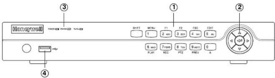
No. Name Function
| 1 Alphanumeric Buttons SHIFT: Switches between number/letter input and function input. | |
| MENU/1: Enters 1; MENU accesses the main menu interface. | |
| 2ABC/F1: Enters 2/A/B/C; F1 selects all items in a list. In live view or playback mode, F1 switches between main and spot video output. In PTZ mode, F1 zooms out PTZ camera. | |
| 3DEF/F2: Enters 3/D/E/F; F2 cycles through tabbed pages. In PTZ mode, F2 zooms in PTZ camera. | |
| 4GHI/ESC: Enters 4/G/H/I; ESC returns to previous menu. | |
| 5JKL/EDIT: Enters 5/J/K/L; EDIT deletes characters before cursor, selects check boxes and on/off switches. In playback mode, EDIT starts/stops playback. | |
| 6MNO/PLAY: Enters 6/M/N/O. In playback mode, PLAY accesses the playback interface. | |
| 7PQRS/REC: Enters 7/P/Q/R/S; REC accesses the manual recording interface, manually starts/stops recording. | |
| 8TUV/PTZ: Enters 8/T/U/V; PTZ accesses the PTZ control interface. | |
| 9WXYZ/PREV: Enters 9/W/X/Y/Z. In live view mode, PREV enables multi-camera display. In playback mode, PREV deletes selected tag. | |
| 0/A: Enters 0; A switches between uppercase and lowercase letters, symbols, numeric input). In playback mode, A adds default tag. | |
| 2 Direction/Enter Buttons | Direction buttons move the cursor up/down/left/right (▲▼◀▶). In live view mode, the direction buttons cycle through channels. In playback mode, up/down buttons speed up/slow down playback. In PTZ mode, the direction buttons control PTZ camera movement. |
| The Enter button (↔) selects a menu item or executes a selection. | |
| 3 LED Indicators | POWER: Lights green when DVR is receiving power. |
| STATUS: Lights red when DVR hard drive is reading/writing. | |
| Tx/Rx: Flashes green when network connection is active. | |
| 4 USB Port Connects USB device (such as a flash drive for saving video clips). | |
The following illustration shows the front panel of the 8/16-channel HRGX DVR.
Figure 1-2 HRGX8/HRGX16 Front Panel
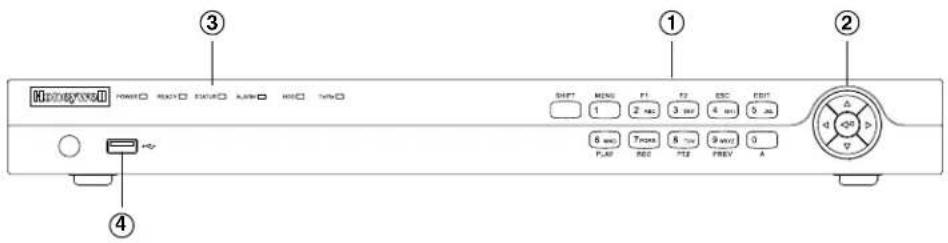
No. Name Function
| 1 Alphanumeric Buttons SHIFT: Switches between number/letter input and function input. | |
| MENU/1: Enters 1; MENU accesses the main menu interface. | |
| 2ABC/F1: Enters 2/A/B/C; F1 selects all items in a list. In live view or playback mode, F1 switches between main and spot video output. In PTZ mode, F1 zooms out PTZ camera. | |
| 3DEF/F2: Enters 3/D/E/F; F2 cycles through tabbed pages. In PTZ mode, F2 zooms in PTZ camera. | |
| 4GHI/ESC: Enters 4/G/H/I; ESC returns to previous menu. | |
| 5JKL/EDIT: Enters 5/J/K/L; EDIT deletes characters before cursor, selects check boxes and on/off switches. In playback mode, EDIT starts/stops playback. | |
| 6MNO/PLAY: Enters 6/M/N/O. In playback mode, PLAY accesses the playback interface. | |
| 7PQRS/REC: Enters 7/P/Q/R/S; REC accesses the manual recording interface, manually starts/stops recording. | |
| 8TUV/PTZ: Enters 8/T/U/V; PTZ accesses the PTZ control interface. | |
| 9WXYZ/PREV: Enters 9/W/X/Y/Z. In live view mode, PREV enables multi-camera display. In playback mode, PREV deletes selected tag. | |
| 0/A: Enters 0; A switches between uppercase and lowercase letters, symbols, numeric input). In playback mode, A adds default tag. | |
| 2 Direction/Enter Buttons | Direction buttons move the cursor up/down/left/right (▲▼◄►). In live view mode, the direction buttons cycle through channels. In playback mode, up/down buttons speed up/slow down playback. In PTZ mode, the direction buttons control PTZ camera movement. |
| The Enter button (←) selects a menu item or executes a selection. | |
| 3 LED Indicators | POWER: Lights green when DVR is receiving power. |
| READY: Lights blue when DVR is operating properly. | |
| STATUS: Lights blue when DVR is controlled by IR remote. Lights red when DVR is controlled by keyboard. Lights orange when DVR is being controlled by IR remote and keyboard at the same time. | |
| ALARM: Lights red when a sensor alarm is detected. | |
| HDD: Flashes red when DVR hard drive is reading/writing. | |
| Tx/Rx: Flashes green when network connection is active. | |
| 4 USB Port Connects USB device (such as a flash drive for saving video clips). | |
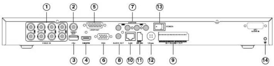
Rear Panel Layout
The following illustration shows the rear panel of the 4-channel HRGX DVR.
Figure 1-3 HRGX4 Rear Panel
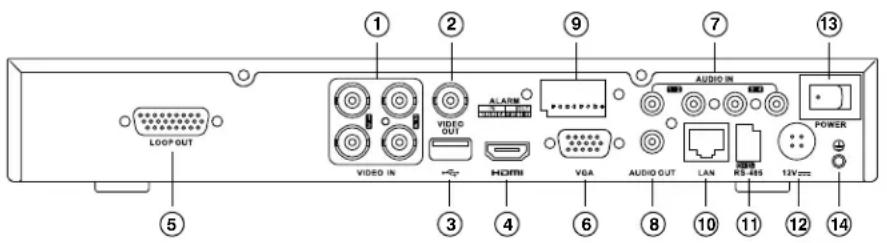
No. Name Description
| 1 Video In BNC connectors for analog video input | |
| 2 Video Out BNC connector for analog video output | |
| 3 USB Port Connects USB device (such as a USB mouse) | |
| 4 HDMI HDMI connector for high definition digital video output | |
| 5 Loop Out DB26 socket for independent video output | |
| 6 VGA Port DE15 socket for local video output | |
| 7 Audio In RCA connectors for audio input | |
| 8 Audio Out RCA connector for audio output | |
| 9 Alarm In/Out Connector for alarm input/output | |
| 10 LAN Port | RJ45 10/100M Ethernet interface |
| 11 RS-485 | Connects RS-485 devices. Connect D+ and D- terminals to R+ and R- terminals of PTZ receiver. |
| 12 12V | 12 V DC power input |
| 13 Power Switch | Switch for turning DVR on/off |
| 14 GND | Ground terminal (needs to be connected before DVR is turned on) |
The following illustration shows the rear panel of the 8-channel HRGX DVR.
Figure 1-4 HRGX8 Rear Panel
No. Name Description
| 1 Video In BNC connectors for analog video input | |
| 2 Video Out BNC connector for analog video output | |
| 3 USB Port Connects USB device (such as a USB mouse) | |
| 4 HDMI HDMI connector for high definition digital video output | |
| 5 Loop Out DB26 socket for independent video output | |
| 6 VGA Port DE15 socket for local video output | |
| 7 Audio In RCA connectors for audio input | |
| 8 Audio Out RCA connector for audio output | |
| 9 Alarm In/Out Connector for alarm input/output | |
| 10 LAN Port RJ45 10/100M Ethernet interface | |
| 11 RS-485 | Connects RS-485 devices. Connect D+ and D- terminals to R+ and R- terminals of PTZ receiver. |
| 12 12V | 12 V DC power input |
| 13 Power Switch | Switch for turning DVR on/off |
| 14 GND | Ground terminal (needs to be connected before DVR is turned on) |
The following illustration shows the rear panel of the 16-channel HRGX DVR.
Figure 1-5 HRGX16 Rear Panel

No. Name Description
| 1 Video In BNC connectors for analog video input | |
| 2 Video Out BNC connector for analog video output | |
| 3 USB Port Connects USB device (such as a USB mouse) | |
| 4 HDMI HDMI connector for high definition digital video output | |
| 5 Loop Out DB26 socket for independent video output | |
| 6 VGA Port DE15 socket for local video output | |
| 7 Audio In RCA connectors for audio input | |
| 8 Audio Out RCA connector for audio output | |
| 9 Alarm In/Out Connector for alarm input/output | |
| 10 LAN Port | RJ45 10/100M Ethernet interface |
| 11 RS-485 | Connects RS-485 devices. Connect D+ and D- terminals to R+ and R- terminals of PTZ receiver. |
| 12 12V | 12 V DC power input |
| 13 Power Switch | Switch for turning DVR on/off |
| 14 GND | Ground terminal (needs to be connected before DVR is turned on) |
Mouse Operation
It is recommended that you use the supplied mouse to set up and operate your HRGX DVR. To use the mouse, connect the mouse cable to the USB port at the rear of the DVR. The mouse should be detected automatically.
Note If you prefer, you can use your own mouse instead of the supplied mouse. Ask your Honeywell dealer for a list of compatible mice.
The following table describes basic mouse operations:
| Name Action Description | ||
| Left Mouse Button | Click | Live view: Select channel and display quick set menu.Menu: Select and enter. |
| Double-click Live view: Switch between single-screen and multi-screen. | ||
| Press and drag | Live view: Select time bar.PTZ control: Pan, tilt, and zoom.Privacy masking and motion detection: Select target area.Digital zoom: Select target area. | |
| Right Mouse Button Click | Live view: Show menu.Menu: Exit menu. | |
| Scroll Wheel | Scroll up | Live view: Go to previous screen.Shortcut menu: Go to previous item. |
| Scroll down | Live view: Go to next screen.Shortcut menu: Go to next item. | |
Remote Control Operation
Although it is recommended to use a mouse to set up and operate your HRGX DVR, you can also use the supplied IR remote control. Two AAA batteries (not included) must be installed before use.
The following illustration shows the layout of the remote control.
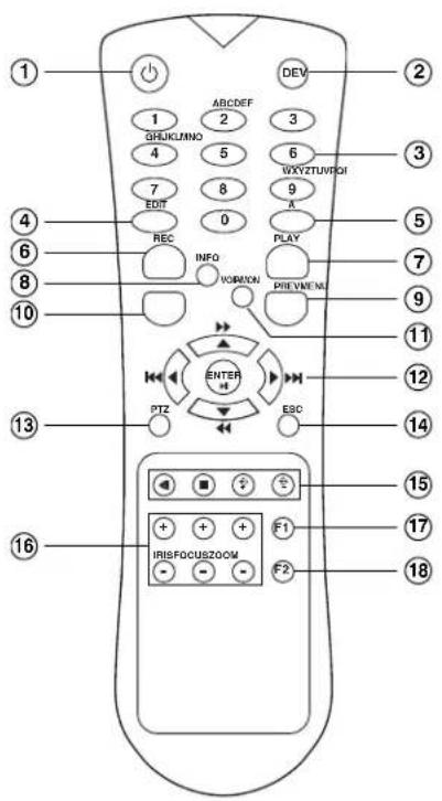
| No. | Button Function | |
| 1 | Power Turns DVR on/off. | |
| 2 | DEV Enables/disables remote control. | |
| 3 | Alphanumeric Inputs numbers/characters in edit mode. Selects channel to view in live view and playback mode. | |
| 4 | EDIT Deletes characters before cursor, selects check boxes in edit mode. Generates video clips for backup in playback mode. | |
| 5 | A Switches between uppercase and lowercase letters, symbols, numeric input. | |
| 6 | REC Accesses manual record menu. Calls preset in PTZ mode (press REC, then preset number). | |
| 7 | PLAY | Accesses all-day playback menu. |
| 8 | INFO | Reserved |
| 9 | PREV | Switches between single screen and multi-screen layout in live view mode. |
| 10 | MENU | Accesses main menu. |
| 11 | VOIP/MON | Selects all items in a list. |
| 12 | Direction/ ENTER | Move cursor up/down/left/right in edit mode. Cycle through channels in live view mode. In playback mode, up/down buttons speed up/slow down playback, left/right buttons jump back/forward 30 s. |
| 13 | PTZ | Enters PTZ control mode. |
| 14 | ESC Returns to previous menu. | |
| 15 | RESERVED | Reserved |
| 16 | PTZ Controls | Control iris, focus, and zoom of PTZ camera. |
| 17 | F1 | Selects all items in a list. |
| 18 | F2 | Cycles through tabbed pages. |
Pairing the Remote Control with the DVR
To pair the remote control with the DVR, follow these steps:
- Turn on the DVR.
- Using the mouse, log in to the DVR.
- Right-click anywhere on the screen to display the shortcut menu, and then click Menu.
- If prompted, enter the DVR's admin password. The default admin password is 12345.
- In the main menu, click Settings.
- In System Settings, on the General page, click the More Settings tab.
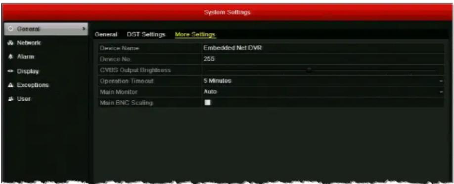
- Make a note of the device number of the DVR. The default device number is 255.
- Press the DEV button on the remote control, input the device number, and then press the ENTER button.
Troubleshooting the Remote Control
If there is no response when you try to use the remote control, follow these steps:
- Check that the batteries are properly installed. Ensure that the polarities are not reversed.
- Check that the IR receiver on the DVR front panel is not obstructed.
- Aim the remote control at the IR receiver.
If the problem persists, contact your Honeywell dealer for a replacement.
Menu Structure
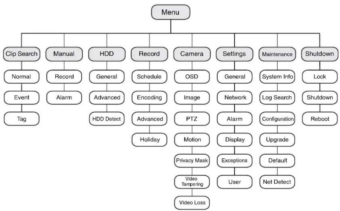
flowchart
graph TD
    A["Menu"] --> B["Clip Search"]
    A --> C["Manual"]
    A --> D["HDD"]
    A --> E["Record"]
    A --> F["Camera"]
    A --> G["Settings"]
    A --> H["Maintenance"]
    A --> I["Shutdown"]
    B --> J["Normal"]
    J --> K["Event"]
    K --> L["Tag"]
    C --> M["Record"]
    M --> N["Alarm"]
    D --> O["General"]
    O --> P["Advanced"]
    P --> Q["HDD Detect"]
    E --> R["Schedule"]
    R --> S["Encoding"]
    S --> T["Advanced"]
    T --> U["Holiday"]
    F --> V["OSD"]
    V --> W["Image"]
    W --> X["PTZ"]
    X --> Y["Motion"]
    Y --> Z["Privacy Mask"]
    Z --> AA["Video Tampering"]
    AA --> AB["Video Loss"]
    G --> AC["General"]
    AC --> AD["Network"]
    AD --> AE["Alarm"]
    AE --> AF["Display"]
    AF --> AG["Exceptions"]
    AG --> AH["User"]
    H --> AI["System Info"]
    AI --> AJ["Log Search"]
    AJ --> AK["Configuration"]
    AK --> AL["Upgrade"]
    AL --> AM["Default"]
    AM --> AN["Net Detect"]
    I --> AO["Lock"]
    AO --> AP["Shutdown"]
    AP --> AQ["Reboot"]
2
Getting Started
This chapter contains the following sections:
• Installation Precautions, page 23
- Connecting External Devices, page 24
- Starting Up and Shutting Down the DVR, page 27
• Using the Setup Wizard, page 28
- Accessing the Main Menu, page 31
- Setting the System Date and Time, page 32
- Upgrading the Firmware, page 33
• HDD Storage Calculation, page 34
Installation Precautions
Follow these precautions when installing the DVR:
- Use brackets for rack mounting.
- Ensure that there is at least 0.75 in. (2 cm) of space between rack-mounted devices.
- Ensure that there is ample room for the audio and video cables.
- When installing cables, ensure that the bend radius of the cable is at least five times the cable diameter.
- Ensure that the DVR is properly grounded.
- Ensure that the environmental temperature is between 14^ (-10^) and 131^ (55^) .
- Ensure that the environmental humidity is between 10 percent and 90 percent.
Connecting External Devices
Video, audio, network, and other connections are made using the rear panel connectors (see Rear Panel Layout, page 16).
Connecting Cameras
Connect the coaxial cables from the cameras to the Video In BNC connectors.
Connecting Monitors
Connect your main video monitor to the VGA or HDMI output. Connect a spot monitor, if used, to the Video Out BNC connector.
Connecting Audio Devices
To record audio, connect your audio sources to the Audio In RCA connectors. To play audio, connect a speaker to the Audio Out RCA connector.
Connecting to a Local Area Network
Connect a Cat5 Ethernet cable to the LAN RJ45 jack.
Connecting a Mouse
Connect the supplied USB mouse to the rear panel USB port. This leaves the front panel USB port available for importing data from, or exporting data to, a USB flash drive.
Connecting a PTZ Camera or Other RS-485 Device
Connect the R+ and R- terminals of the PTZ receiver or other RS-485 device to the D+ and D- terminals of the RS-485 interface. Press and hold the orange part of the terminal block, insert the wire, then release the orange part to lock the wire in place.
Connecting Alarm Devices
Connect alarm devices to the Alarm In/Out interface. Press and hold the orange part of the terminal block, insert the wire, then release the orange part to lock the wire in place.
Alarm Input
The alarm input should be an open/closed dry contact relay. If an open/closed relay is not used, connect the alarm input as follows:
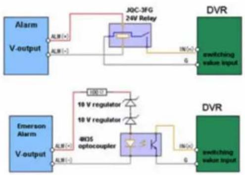
flowchart
graph TD
    A["Alarm V-output"] -->|ALR (+)| B["J0C-3FG 24V Relay"]
    B -->|IN (+)| C["DVR switching value input"]
    D["Emerson Alarm V-output"] -->|ALR (-)| E["18 V regulator"]
    E --> F["18 V regulator"]
    F --> G["4KOS optocoupler"]
    G --> H["DVR switching value input"]
Alarm Output
The alarm output relay supports connections to AC/DC loads. DC loads must be within the limit of 12 V DC / 1 A.
Refer to the following diagram when connecting to AC/DC loads:
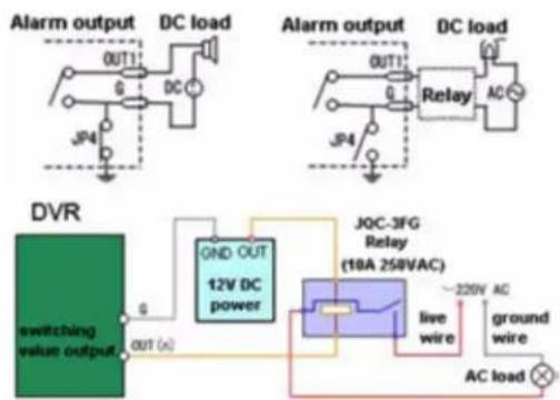

CAUTION Risk of electric shock. An external relay is necessary to prevent electric shock when connecting to an AC load.
Connecting Power
Connect the supplied power adapter to the 12 V DC power input. It is strongly recommended that you use an uninterruptible power supply when powering the DVR.
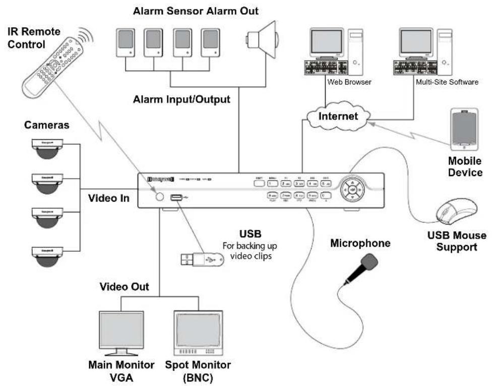
Typical Installation
The following diagram shows a typical HRGX DVR installation:
flowchart
graph TD
    A["IR Remote Control"] --> B["Cameras"]
    B --> C["Video In"]
    C --> D["USB For backing up video clips"]
    D --> E["Microphone"]
    E --> F["USB Mouse Support"]
    F --> G["Mobile Device"]
    G --> H["Internet"]
    H --> I["Web Browser"]
    I --> J["Multi-Site Software"]
    J --> K["Alarm Sensor Alarm Out"]
    K --> L["Alarm Input/Output"]
    L --> M["Main Monitor VGA"]
    L --> N["Spot Monitor (BNC)"]
    M --> O["Video Out"]
    N --> P["Video In"]
Starting Up and Shutting Down the DVR
Following correct startup and shutdown procedures will help to prolong the life of your DVR. Before you begin, ensure that all extension cords, surge protectors, and uninterruptible power supplies used with the DVR are rated to handle the DVR's electrical requirements, and ensure that the DVR is properly grounded.
To turn on the DVR:
- Ensure that the DVR is connected to a suitable power source.
- Turn on the power switch on the rear panel of the DVR. The POWER LED on the front panel lights solid green when the DVR is receiving power.
Note The DVR takes approximately 45 seconds to initialize after it is turned on.
To turn off the DVR:
Note To shut down the DVR, you must be logged in as the admin user or else have shutdown privileges assigned to you.
- In live view mode, right-click anywhere on the screen to display the shortcut menu, and then click Menu.
- If prompted, enter the DVR's admin password. The default admin password is 12345.
- In the main menu, click Shutdown.
- In the Shutdown menu, click Shutdown.
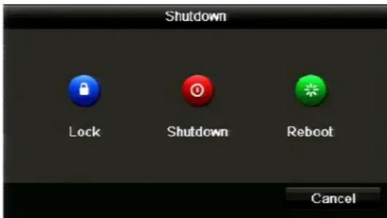
- Click Yes to confirm that you want to shut down the system.
- Turn off the power switch on the rear panel of the DVR.
Using the Setup Wizard
The setup wizard starts by default when you turn on the DVR. The wizard will guide you through the initial setup of the DVR.
Note It is strongly recommended that you use the supplied mouse to set up and operate the DVR. If you have not already done so, plug the mouse into the USB on the rear panel of the DVR.
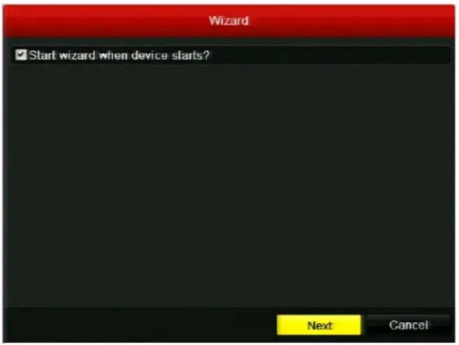
- The Start wizard when device starts? check box is enabled by default. If you want to stop the setup wizard from starting each time you turn on the DVR, clear the check box.
-
Click Next to continue to the next screen.
-
Click the Admin Password field to display the on-screen numerical keypad, enter your DVR's admin password (the default admin password is 12345), and then click Enter.

- If you want to create a new password, select the New Admin Password check box, enter a new password in the New Password field, and then re-enter the new password in the Confirm field.
- Click Next to continue to the next screen.
- Specify your DVR's network settings. If you want to configure the IP address, subnet mask, default gateway, and DNS addresses manually, clear the Enable DHCP check box.
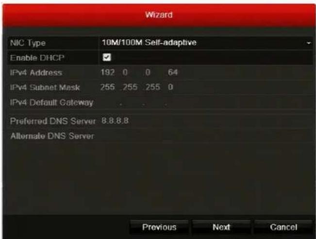
-
Click Next to continue to the next screen.
-
Select a camera, and then specify the desired recording resolution, frame rate, and recording time. You can use the DiskCalculator storage estimator tool included with your DVR to help you determine these settings. See also HDD Storage Calculation, page 34.
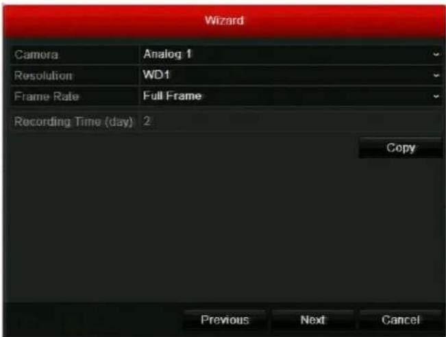
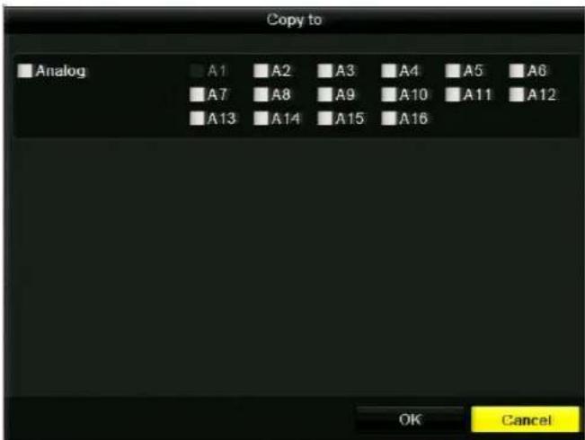
- Specify the recording settings for each camera that is connected to your DVR. To copy the same settings to one or more additional cameras, click Copy, select the check boxes of the channel(s) that you want to copy the settings to (or select the Analog check box to select all the channels), and then click OK.
-
Click Next to continue to the next screen.
-
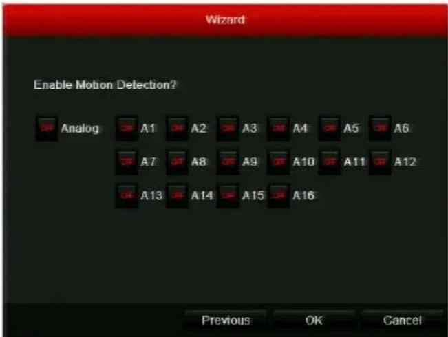
Motion detection is disabled for all channels by default. Click the channel(s) that you want to enable motion detection for, or click Analog to select all channels, and then click OK.
Accessing the Main Menu
Use the following procedure to access the main menu.
To access the main menu:
- In live view mode, right-click anywhere on the main monitor screen to display the shortcut menu, and then click Menu.
- If prompted, enter the DVR's admin password, and then click OK. The default admin password is 12345.
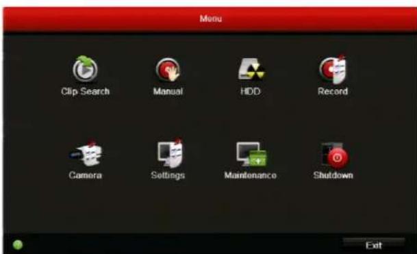
- In Menu, click the submenu you want to open: Clip Search, Manual, HDD, Record, Camera, Settings, Maintenance, or Shutdown.
Setting the System Date and Time
Before you begin using the DVR, set the system date and time to ensure that recordings and events are time-stamped accurately.
To set the system date and time:
- Go to Menu > Settings. The System Settings window opens.
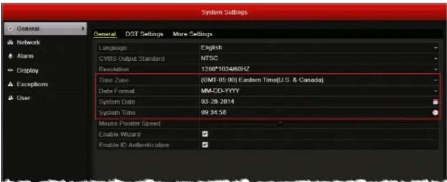
- On the General page, under General, configure the following settings:
• Time Zone Select your time zone from the list.
- Date Format Select MM-DD-YYYY, YYYY-MM-DD, or DD-MM-YYYY.
- System Date Click the calendar icon to display the on-screen calendar, and then select the current date.
- System Time Click the clock icon, and then enter the current time (hh:mm:ss).
- Click Apply to save your settings.
Upgrading the Firmware
To obtain the latest firmware for your HRGX DVR, contact your Honeywell dealer. The firmware can be upgraded locally (by connecting a USB flash drive or other device containing the firmware file to the DVR) or remotely (via an FTP server).
To upgrade the firmware locally:
-
Insert a USB flash drive containing the digicap.dav file into the USB port on the front of the DVR. Ensure that no other USB flash drive or storage device is connected to the DVR.
-
Go to Menu > Maintenance > Upgrade > Local Upgrade. The digicap.dav file should appear in the file list under Local Upgrade.
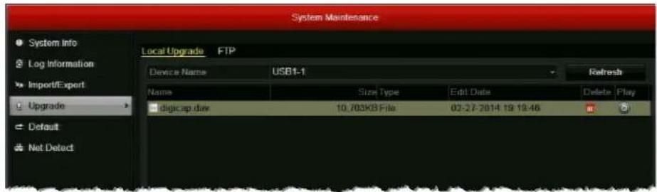
- Click digicap.dav, and then click Upgrade. The DVR restarts automatically after the upgrade is complete.
To upgrade the firmware remotely via FTP:
-
Ensure that your DVR and the PC running the FTP server are properly connected to the network and that the digicap.dav file is saved in the appropriate directory on the PC.
-
Go to Menu > Maintenance > Upgrade > FTP.
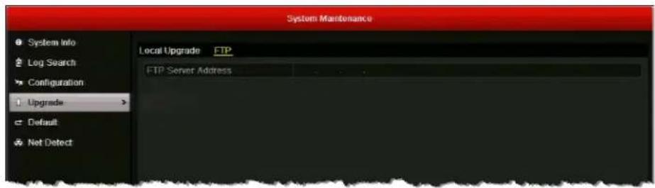
-
In the FTP Server Address field, enter the address of the FTP server you want to access, and then click Upgrade.
-
After the firmware upgrade is complete, restart the DVR.
HDD Storage Calculation
The following table estimates storage space usage based on recording one channel for hour at a fixed bit rate. Actual usage will vary.
| Bit Rate (Kbps) Storage Used (MB) | |
| 96 42 | |
| 128 56 | |
| 160 70 | |
| 192 84 | |
| 224 98 | |
| 256 112 | |
| 320 140 | |
| 384 168 | |
| 448 196 | |
| 512 225 | |
| 640 281 | |
| 768 337 | |
| 896 393 | |
| 1024 450 | |
| 1280 562 | |
| 1536 675 | |
| 1792 787 | |
| 2048 900 | |
| 3072 1350 | |
Viewing Live Video
This chapters contains the following sections:
- About Live View, page 35
- Configuring Live View Settings, page 37
• Operations in Live View, page 43
About Live View
Live view mode is the DVR's default mode. When you start the DVR, live video from the connected cameras displays automatically on the monitor.
On-Screen Notifications
The following icons appear in the upper right corner of each channel's screen when the camera is recording and/or when an event alarm has been triggered:

Indicates video is being recorded. This may be a scheduled recording, a recording initiated manually by the DVR operator, or it may be initiated by motion or a relay alarm.

Indicates video loss/tampering, motion detection, or a relay alarm.
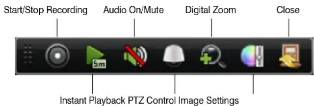
Quick Setting Toolbar
The following toolbar appears when you click on a channel in live view mode:
Shortcut Menu
The following menu appears when you right-click on the screen in live view mode:
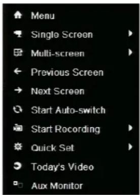
| Name Description |
| Menu Enter the main menu. |
| Single Screen Switch to full screen view. Select channel from list. |
| Multi-screen Switch to multi-screen view. Select option from list. |
| Previous Screen Go to previous channel. |
| Next Screen Go to next channel. |
| Start Auto-switch Enable auto-switching between channels. |
| Start Recording Start all-day normal recording or motion detection recording for all channels. |
| Quick Set Set video output mode to Standard, Bright, Gentle, or Vivid. |
| Today's Video Play back day's video of current channel. |
| Aux Monitor Disable main output and switch to auxiliary output. Aux monitor must be connected. |
Configuring Live View Settings
Setting the Screen Layout
The live view interface is configurable as a single channel for multiple camera display (4, 8, or 16 channels depending on your DVR model).
To display video from a single channel full screen:
- Double-click the channel that you want to view full screen.
- Right-click anywhere on the screen to display the shortcut menu, click Single Screen, and then click the channel you want to view from the list (for example, "Camera 03").
Note You can alternate between single channel (full screen) and multi-channel display modes by double-clicking the left mouse button. In full screen mode, use the scroll wheel on the mouse to switch between channels. Moving the scroll wheel up displays the previous channel and moving the scroll wheel down displays the next channel.
To display video from multiple channels simultaneously:
- Right-click anywhere on the screen to display the shortcut menu, and then click Multi-screen.
- Select a display mode from the list (the options will vary depending on the number of channels your DVR supports).
Setting the Video Output Mode
There are four video output modes in live view: Standard, Bright, Gentle, and Vivid. The default output mode is Bright.
To change the video output mode, right-click anywhere on the screen to display the shortcut menu, click Quick Set, click Output Mode, click the output mode you want, and then click OK.
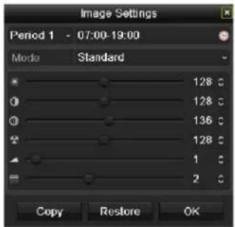
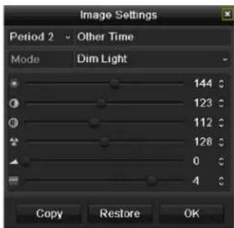
Configuring Camera Image Settings
You can create customized image settings for up to two time periods per camera to accommodate changing lighting conditions.
To configure image settings:
- Click on a channel to display the quick setting toolbar (see
Quick Setting Toolbar, page 35).
- On the toolbar, click the Image Settings button

-
In the Image Settings window, next to Period 1, specify the time range that you want to configure the image settings for (such as 07:00–19:00).
-
Based on the anticipated lighting conditions for the specified time range, next to Mode, select one of the following:
-
Standard (default)
- l n d o o r
- Dim Light
-
Outdoor
-
Adjust the following image settings by moving the slider or by clicking the up/down arrows:
-
Brightness (0–255)
- Contrast (0–255)
- Saturation (0–255)
- Hue (0–255)
- Sharpness (0–15)
-
De-noising (0–5)
-
If you want to define different image settings for the remaining time (such as 19:01 to 06:59), select Period 2, and then repeat steps 4 and 5.
- To copy these settings to one or more additional cameras, click Copy to open the Copy to window, select the camera(s) you want to copy the settings to, or click Analog to copy the settings to all cameras, and then click OK.
- Click OK to save your settings.
Configuring System Display Settings
This section describes how to configure general display settings, set the camera order, enable/disable live view for one or more cameras, and set up channel-zero encoding.
Configuring General Display Settings
You can configure general display settings in the System Settings menu. Follow the instructions below to set up video and audio outputs, the live view screen layout, and the auto-switching dwell time.
To configure general display settings:
1. Go to Menu > Settings > Display.
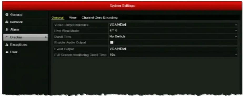
2. On the Display page, under General, configure the following settings:
• Video Output Interface
Sets the main video output for live view and playback mode. Select VGA/HDMI (default) or Main BNC.
- Live View Mode
Sets the screen layout for live view mode. Available options are dependent on DVR type.
- Dwell Time
Sets the channel switching interval time in seconds when auto-switching is enabled in live view mode. Select a value between 5 s and 300 s or select No Switch.
- Enable Audio Output
Select/clear the check box to enable/disable audio output for the selected main video output.
- Event Output
Sets the video output for event recording. Select VGA/HDMI (default) or Main BNC.
• Full Screen Monitoring Dwell Time
Sets the time in seconds to show alarm events on screen.
3. Click Apply to save your settings.
Note When the VGA/HDMI output interface is used as the main video output and Audio Output is enabled, the VGA/HDMI audio and AUDIO OUT can be used for live view, playback and two-way audio. If Audio Output for the VGA/HDMI output interface is disabled, the VGA/HDMI output provides no audio and the AUDIO OUT is used for two-way audio.
When the Main BNC output is used as the main video output, the VGA/HDMI audio is provided for Aux video output in live view, and the AUDIO OUT is used as the main video output (for live view, playback or two-way audio).
Setting the Camera Order
You can set the order in which the cameras appear on screen in live view mode in the System Settings menu.
To set the camera order:
- Go to Menu > Settings > Display > View.
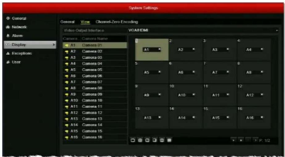
- In the Video Output Interface list, select VGA/HDMI or Main BNC as your main video output.
- Select a screen on the right and then, from the list of cameras on the left, double-click the camera you want to assign to that screen. The camera number (for example, "A1") appears in the selected screen. You can assign the cameras to up to 32 screens in any order.
- Click Apply to save your settings.
Enabling or Disabling Live View
You can enable or disable the live video feed (live view) for one or more cameras in the System Settings menu.
To enable/disable live view:
-
Go to Menu > Settings > Display > View.
-
Do one of the following:
-
To enable live view for a single camera, double-click the camera name. The camera icon changes to yellow. To disable live view for a single camera, double-click the camera name again or click the × in the corresponding screen. The camera icon changes to white.
- To enable live view for all cameras, click the play button ▷. The camera icons for all cameras change to yellow. To disable live view for all cameras, click the stop button □. The camera icons for all cameras change to white.
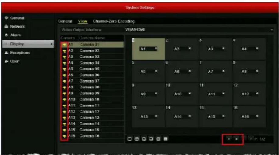
- Click Apply to save the setting.
Enabling or Disabling Channel-Zero Encoding
You can enable or disable channel-zero encoding in the System Settings menu. With channel-zero encoding enabled you can remotely view real-time video from multiple channels in one screen, minimizing bandwidth usage while preserving image quality.
To enable channel-zero encoding:
- Go to Menu > Settings > Display > Channel-Zero Encoding.
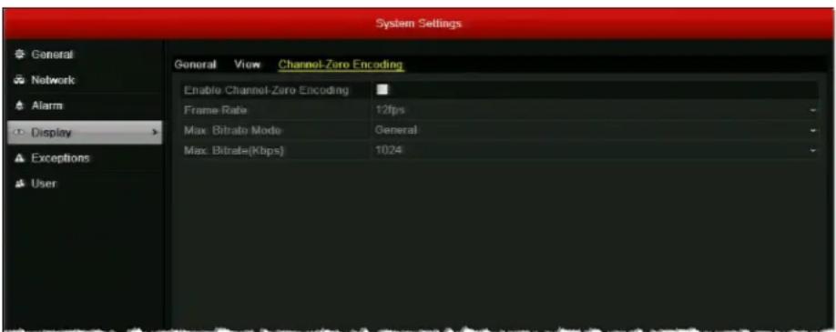
- Select the Enable Channel-Zero Encoding check box.
- Configure the following settings:
- Frame R a t Select a value between 1/8 fps and 12 fps (default).
• Max. Bitrate(Kbps) Select a value between 32 and 2048. The default is 1024.
- Click Apply to save your settings.
To disable channel-zero encoding:
- In System Settings, on the Display page, click the Channel-Zero Encoding tab.
- Clear the Enable Channel-Zero Encoding check box, and then click Apply.
Operations in Live View
Switching Between Channels
In full screen display mode, you can switch between channels manually or you can use the auto-switch function to automatically cycle through each channel's video feed at predetermined intervals.
Note Before you can use the auto-switch function, you must set the dwell time. See Configuring General Display Settings, page 39.
To manually switch to the next channel, do one of the following:
- Scroll down with your mouse. (Scrolling up switches to the previous channel.)
- Right-click anywhere on the screen to display the shortcut menu, and then click Next Screen.
To automatically cycle through the channels:
- Right-click anywhere on the screen to display the shortcut menu, and then click Start Auto-switch.
The DVR starts automatically cycling through each channel. The period of time each channel's video feed appears on the screen is determined by the dwell time you specified in the Display Settings.
To stop cycling through all the channels:
- Right-click anywhere on the screen to display the shortcut menu, and then click Stop Auto-switch.
Main/Aux Output Switching
You can access certain live view mode features using an auxiliary monitor. These features include Single Screen, Multi-screen, Previous Screen, Next Screen, and Quick Set (see Shortcut Menu, page 36).
When HDMI/VGA output is configured as the main output, you can switch to Main BNC output by double-clicking the mouse wheel anywhere on the screen. The message "Double-click the mouse again to switch the auxiliary and main output?" appears. Double-click the mouse wheel again to continue, or click Cancel to cancel the operation.
To switch back to the main HDMI/VGA output, right-click on the screen in live view mode to display the shortcut menu, and then click Main Monitor.
Zooming In
You can use the digital zoom function to enlarge an area of the on-screen image.
To enter digital zoom mode
- Right-click anywhere on the screen to display the shortcut menu, and then click Digital Zoom.
The picture on the screen is magnified by 4 times and the normal screen view appears as an inset window in the lower right corner of the screen. The magnified area is indicated by a red frame. - In the inset window, drag the red frame to the area of the screen you want to zoom in on.
To exit digital zoom mode
• Right-click anywhere on the screen, and then click Exit.
Controlling a PTZ Device
This chapters contains the following sections:
• About PTZ Control, page 45
- Configuring PTZ Settings, page 46
- Calling Presets, Patrols, and Patterns, page 51
About PTZ Control
You can control a connected PTZ camera in live view mode using the on-screen PTZ control interface.
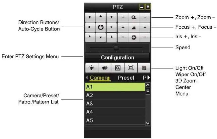
You can access this interface in live view mode by clicking the PTZ Control button 📄 on the quick setting toolbar (see Quick Setting Toolbar, page 35).
Configuring PTZ Settings
Before you can control a PTZ camera, you must configure the connection settings in the Camera Management menu. This section describes how to configure PTZ connection settings, presets, patrols, and patterns.
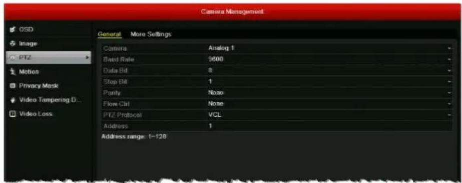
Configuring PTZ Connection Settings
The PTZ connection settings on the DVR must match the settings of the camera. For example, if the PTZ camera has a baud rate as 115200, you should select 115200 in the baud rate field.
To configure the PTZ connection settings:
- Go to Menu > Camera > PTZ > General.
-
Configure the following settings:
-
Cam er Select the PTZ camera you want to configure settings for.
- B a u d R Select your PTZ camera's baud rate setting.
- Data Bit Select your PTZ camera's data bit setting (5, 6, 7, or 8).
- S to p B iSelect your PTZ camera's stop bit setting (1 or 2).
- Parity Select your PTZ camera's parity setting (None, Odd, or Even).
- F I o w C Selectla flow control setting (None, Software, or Hardware).
- PTZ Protocol Select your PTZ camera's protocol.
-
Add r e sEnter your PTZ camera's address.
-
To copy the same settings to one or more additional PTZ cameras, click Copy, select the channel(s) that you want to copy the settings to, or click Analog to select all channels, and then click OK
-
Click Apply to save your settings.
Programming Presets
You can program up to 127 preset positions for the PTZ camera. For example, you can program the camera to point at a specific location, such as a doorway, when an alarm event takes place.
To program a preset:
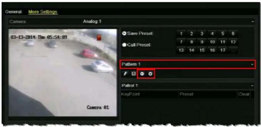
- Go to Menu > Camera > PTZ > More Settings.
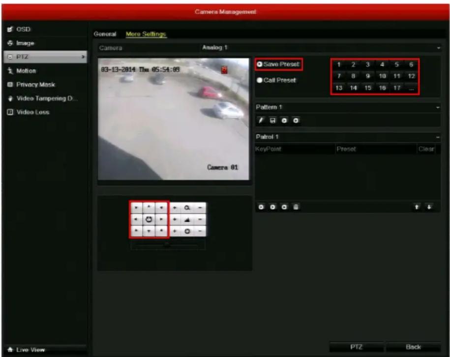
- Use the direction buttons to point the camera at the location where you want to set the preset.
- Click Save Preset, and then click the number you want to assign to the preset. For example, clicking "1" will save the preset as Preset 1, clicking "2" will save the preset as Preset 2, and so on.
- Repeat steps 2 and 3 to save more presets. You can click ... to display additional numbers.
Programming Patrols
You can program the PTZ camera to move automatically from one preset to the next in a specific order and define the length of time the camera remains at each preset. This is called a patrol. You can program up to 3 patrols.
To program a patrol:
- Go to Menu > Camera > PTZ > More Settings.
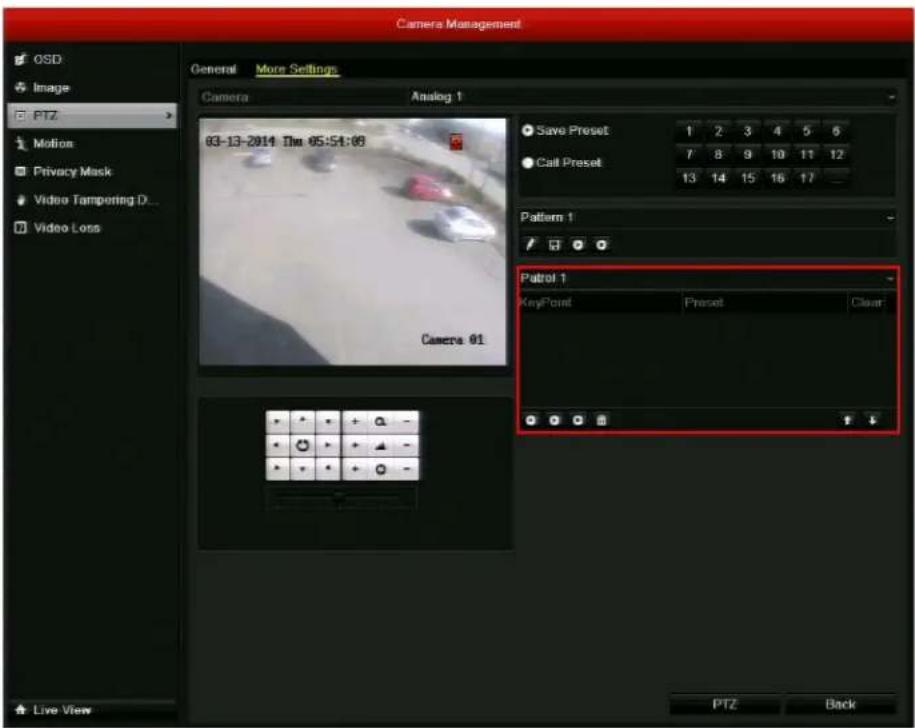
- Select the patrol you want to program from the patrol list (Patrol 1, Patrol 2, or Patrol 3).
- Click the Add KeyPoint button ☐. The KeyPoint window opens.
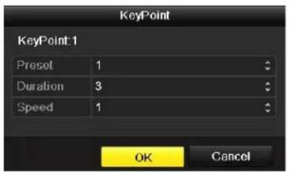
-
In the KeyPoint window, configure the following settings:
-
Preset Select the preset you want to assign to this key point.
- D ur a t i Select the time, in seconds, that you want the camera to remain at this key point.
-
Speed Select the speed at which you want the camera to move to this key point.
-
Click OK to save the key point to the patrol.
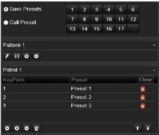
- Repeat steps 3 to 5 to add more key points. To delete a key point from the list, click the Clear button next to the preset name.
Programming Patterns
You can record a set of PTZ movements as a pattern. When you call the pattern in live view mode, the PTZ camera will automatically follow the path you have defined. You can program up to 3 patterns.
To program a pattern:
- Go to Menu > Camera > PTZ > More Settings.
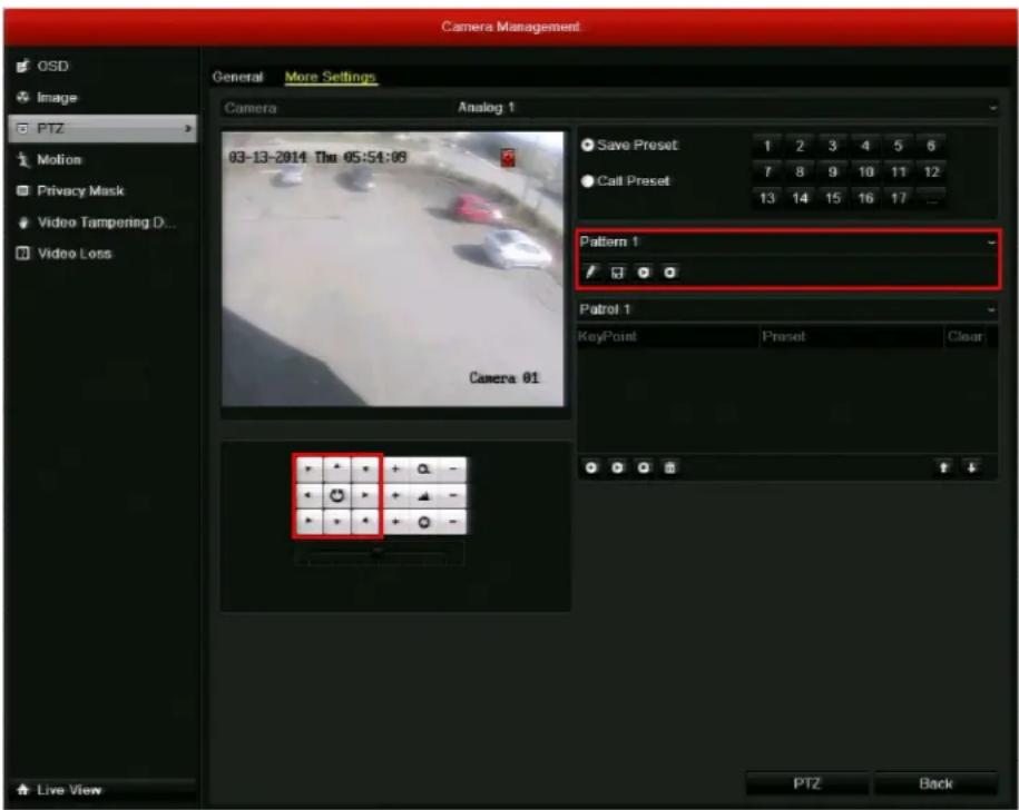
- Select the pattern you want to program from the pattern list (Pattern 1, Pattern 2, or Pattern 3).
- Click the Record button .
- Drag the mouse over the live image, or, alternatively, use the direction buttons, to define the desired path of the PTZ camera.
- Click the Save button ☐ to save the path as the selected pattern.
- Repeat steps 2 to 5 to save more patterns.
Calling Presets, Patrols, and Patterns
This section describes how to call pre-programmed presets, patrols, and patterns in live view mode and within the PTZ configuration interface.
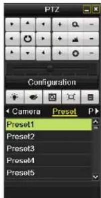
Calling Presets
To call a preset in live view mode:
- Click on a channel to display the quick setting toolbar (see Quick Setting Toolbar, page 35).
- On the toolbar, click the PTZ Control button
- In the on-screen PTZ control interface, under Camera, select your PTZ camera from the list.
- Click Preset to view the list of presets, and then click the preset you want to call.
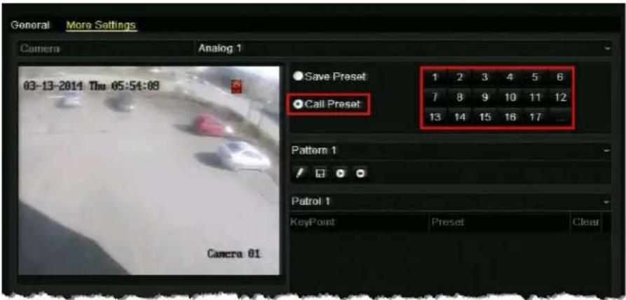
To call a preset in the PTZ configuration interface:
- Go to Menu > Camera > PTZ > More Settings (or click Configuration in the PTZ control interface).
- Click Call Preset, and then click the number of the preset you want to call.
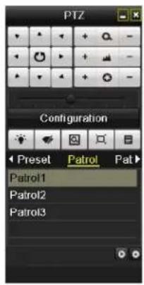
Calling Patrols
To call a patrol in live view mode:
- Click on a channel to display the quick setting toolbar (see Quick Setting Toolbar, page 35).
- On the toolbar, click the PTZ Control button.
- In the on-screen PTZ control interface, under Camera, select your PTZ camera from the list.
- Click Patrol to view the list of patrols, and then click the patrol you want to call.
- Click the start button ☑ to start the patrol. To stop the patrol, click the stop button ☑
To call a patrol in the PTZ configuration interface:
- Go to Menu > Camera > PTZ > More Settings (or click Configuration in the PTZ control interface).
- Select the patrol you want to call from the drop-down list, and then click the Run button to call the patrol. To stop the patrol, click the Stop button

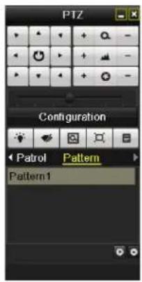
Calling Patterns
To call a pattern in live view mode:
- Click on a channel to display the quick setting toolbar (see Quick Setting Toolbar, page 35).
- On the toolbar, click the PTZ Control button.
- In the on-screen PTZ control interface, under Camera, select your PTZ camera from the list.
- Click Pattern to view the list of patterns, and then click the pattern you want to call.
- Click the start button to start the pattern. To stop the pattern, click the stop button
To call a pattern in the PTZ configuration interface:
- Go to Menu > Camera > PTZ > More Settings (or click Configuration in the PTZ control interface).
- Select the pattern you want to call from the drop-down list, and then click the Run button to call the pattern. To stop the pattern, click the Stop button.
Recording Video
This chapter contains the following sections:
• Live View Record Settings, page 55
- Configuring a Record Schedule, page 56
- Configuring Manual Record Settings, page 58
- Configuring Holiday Record Settings, page 59
- Configuring Encoding Parameters, page 60
- Configuring Redundant Recording, page 63
• Protecting Recorded Files, page 64
Live View Record Settings
In live view mode, you can manually start/stop recording a specific channel or you can start all-day normal or motion detection recording of all channels.
To manually start or stop recording a specific channel:
- In live view mode, click on a channel to display the quick setting toolbar, and then click the Start recording button to start recording video from the channel. To stop recording video from the channel, click the Stop recording button.
To start all-day normal recording of all channels:
- In live view mode, right-click anywhere on the screen to display the shortcut menu, click Start Recording, and then click Normal Record. The message "Start normal all-day recording of all channels?" appears. Click Yes.
To start all-day motion detection recording of all channels:
- In live view mode, right-click anywhere on the screen to display the shortcut menu, click Start Recording, and then click Motion Detection Record. The message "Start all-day motion detection recording of all channels?" appears. Click Yes.
Configuring a Record Schedule
You can set channels to start or stop recording according to a defined schedule.
To configure the schedule:
- Go to Menu > Record > Schedule.
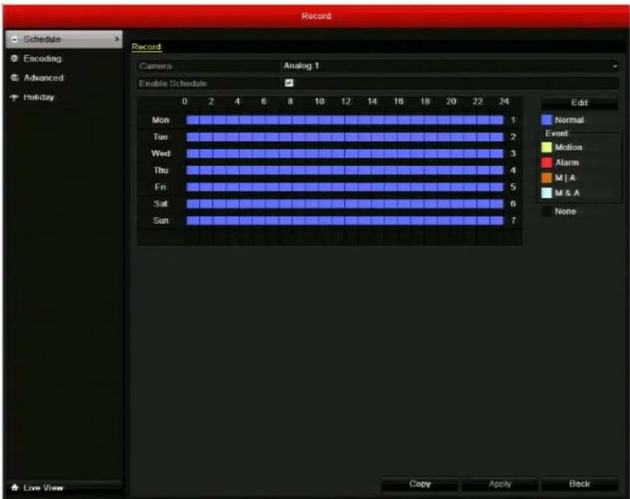
- Select the camera you want to configure the schedule for.
-
Select the Enable Schedule check box.
-
Click Edit. The Edit window opens.
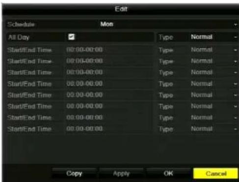
-
In the Schedule list, select the day of the week that you want to set the schedule for. If Holiday settings have been enabled (see Configuring Holiday Record Settings, page 59), you can also select Holiday.
-
You can set the DVR to record video from the selected camera all the time or only at specific times.
-
To set the DVR to record video from the selected camera all the time, select the All Day check box to enable all-day recording, and then, in the Type list, select one of the following recording types: Normal, Motion, Alarm, Motion | Alarm, or Motion & Alarm.
- To set the DVR to record video from the selected camera only at specific times, clear the All Day check box and define the Start/End Time and Type settings for up to 8 non-overlapping time periods.
Note You must configure the alarm input and/or motion detection settings before selecting an event recording type (Motion, Alarm, Motion | Alarm, Motion & Alarm). See Chapter 8, Configuring Alarm Settings.
- To copy these settings to one or more additional days, click Copy to open the Copy to window, select the days(s) you want to copy the settings to, or click All to copy the settings to all days, and then click OK. Alternatively, in Schedule, select another day of the week to set the schedule for and repeat step 6. Do this for each day you want to set the schedule for.
- Click Apply to save your settings, and then click OK. The recording schedule is displayed graphically in the window, with different colors for different recording types.
- To copy these settings to one or more additional cameras, click Copy to open the Copy to window, select the camera(s) you want to copy the settings to, or click Analog to copy the settings to all cameras, and then click OK.
- Click Apply to save your settings, and then click OK.
Configuring Manual Record Settings
You can set the DVR to record channels by manual operation. Manual recording is prior to scheduled recording.
Note Manual recording settings are automatically cleared when the DVR restarts.
To configure manual recording:
- Go to Menu > Manual.
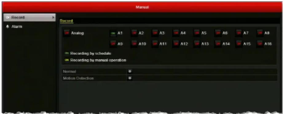
- Click the status button twice next to the channel(s) you want to enable manual recording for, or click the status button twice next to Analog to enable manual recording for all channels.
By default, the channels are set to recording by schedule (green "ON"). Clicking the status button once turns off recording (red "OFF") and clicking it again changes the recording status to recording by manual operation (yellow "ON").
To start all-day normal recording of all channels:
- In Menu > Record, next to Normal, click 📄. The message "Start all-day normal recording of all channels?" appears. Click Yes.
To start all-day motion detection recording of all channels:
- In Menu > Record, next to Motion Detection, click 📄. The message "Start all-day motion detection recording of all channels?" appears. Click Yes.
Configuring Holiday Record Settings
You can set up special recording settings for holidays.
To configure holiday recording settings:
- Go to Menu > Record > Holiday.
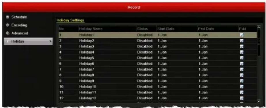
-
Under Holiday Settings, select the holiday you want to configure from the list.
-
Click the Edit button 📋. The Edit window opens.
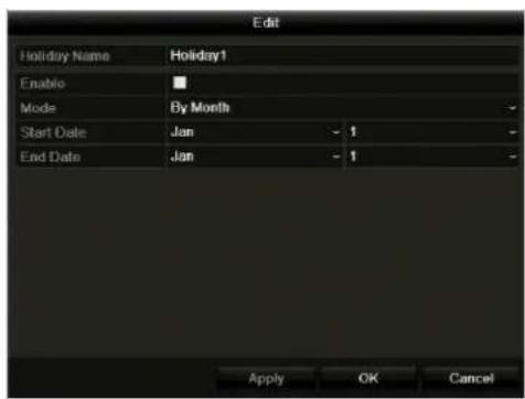
- Configure the following settings:
• H o l i d a Eryter the name of the holiday.
- Enable eSelect/clear the check box to enable/disable this setting.
• M o d e Select By Date, By Week, or By Month.
- Start Date Select the start date for the setting. Format varies by mode.
- E n d D a Select the end date for the setting. Format varies by mode.
- Click Apply to save your settings, and then click OK.
- Set the recording schedule for the holiday. See Configuring a Record Schedule, page 56.
Configuring Encoding Parameters
By configuring the encoding parameters you can define the transmission stream type, the recording resolution, and so on.
To configure encoding parameters for main stream:
- Go to Menu > Record > Encoding > Record.
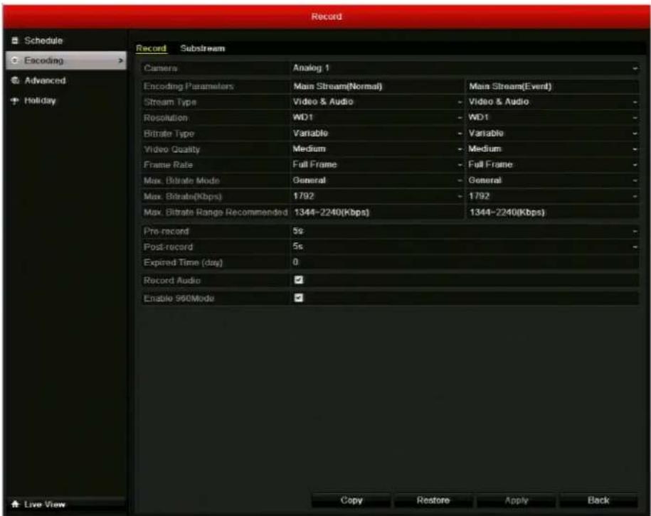
- Select the camera you want to configure encoding parameters for.
-
Configure the following encoding parameters for Main Stream(Normal) and Main Stream(Event):
-
Stream Type pSetethe stream type to Video or Video & Audio.
-
Resolutio Set the recording resolution to one of the following settings: WD1, 4CIF, 2CIF, CIF, or QCIF.
-
Bit rate T y Spt the bitrate type to Variable or Constant.
• Video Quality Set the recording video quality. 6 levels configurable. - Frame Rate eSet the recording frame rate.
- Max. Bitrate Mode Set the bit rate mode to General or Customize .
- Max. Bitrate(Kbps) Select or customize the maximum bit rate for recording.
4. Configure the following settings:
| • Pre - r e c o | Sets the time to record before a scheduled recording time or event. |
| • Post - r e c | Sets the time to record after a scheduled recording time or event. |
| • Ex p i r e d T | Then expired (timel is the longest time a record file can be kept in the HDD. After this, the file is deleted. If the expired time is set to 0, the file will not be deleted. The actual keeping time for the file should be determined by the capacity of the HDD. |
| • Redundant Record | This option is only available when the HDD storage mode is set to Group. Select this check box to simultaneously save recorded video to the redundant HDD. See Configuring Redundant Recording, page 63. |
| • Record Audio | Select the check box to record video with sound. Clear the check box to record video without sound. |
| • Enable 960Mode | Select the check box to enable encoding at WD1 resolution. Clear the check box to disable it. |
5. To copy these settings to one or more additional cameras, click Copy to open the Copy to window, select the camera(s) you want to copy the settings to, or click Analog to copy the settings to all cameras, and then click OK.
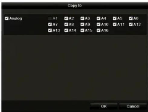
6. Click Apply to save your settings.
Note To restore the current substream settings to the default parameters, click Restore.
To configure encoding parameters for substream:
- Go to Menu > Record > Encoding > Substream.
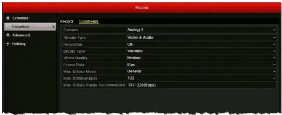
-
Select the camera you want to configure encoding parameters for.
-
Configure the following encoding parameters for substream:
• Stream Ty Set the stream type to Video or Video & Audio.
- Resoluti oSethe recording resolution to one of the following settings: WD1, 4CIF, 2CIF, CIF, or QCIF.
- Bit rate T ySet the bitrate type to Variable or Constant.
• Video Quality Set the recording video quality. 6 levels configurable.
• Frame R at Set the recording frame rate.
- Max. Bitrate Mode Set the bit rate mode to General or Customize.
• Max. Bitrate(Kbps) Select or customize the maximum bit rate for recording.
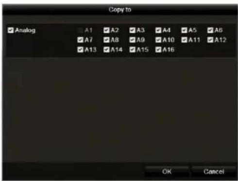
- To copy these settings to one or more additional cameras, click Copy to open the Copy to window, select the camera(s) you want to copy the settings to, or click Analog to copy the settings to all cameras, and then click OK.
- Click Apply to save your settings.
- To restore the current substream settings to the default parameters, click Restore.
Configuring Redundant Recording
If you have two or more HDDs, with the HDD storage mode set to Group (see Configuring HDD Groups, page 117), you can enable redundant recording—that is, you can set up the DVR to save recorded video not only on the R/W (read/write) HDD but also on the redundant HDD for additional security and reliability.
To configure redundant recording:
- Go to Menu > HDD > General.
- Under HDD Information, select the HDD you want to configure as the redundant HDD, and then click the Edit button to open the Local HDD Settings window.
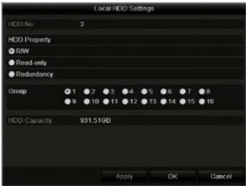
- Click Read-only, click Apply to save the setting, and then click OK.
- Go to Menu > Record > Encoding > Record.
- In the Camera list, select the camera you want to record to both the R/W and Read-only HDDs.
- Select the Redundant Record check box.
- To copy these settings to one or more additional cameras, click Copy to open the Copy to window, select the camera(s) you want to copy the settings to, or click Analog to copy the settings to all cameras, and then click OK.
- Click Apply to save your settings.
Protecting Recorded Files
You can lock individual recorded video files or set the HDD property to read-only to protect recorded video from being overwritten. You can also disable the default overwrite setting in Menu > Record > Advanced.
Note To set the HDD property to read-only, the storage mode of the HDD must be set to Group. See Configuring HDD Groups, page 117.
To lock recorded video files:
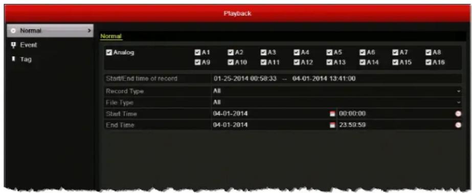
- Go to Menu > Clip Search > Normal.
-
Under Normal, select the channel(s) you want to search, or click Analog to select all the channels.
-
Configure the following search parameters:
-
Record Select one of the following recording types: Normal, Motion, Alarm, Motion | Alarm, Motion & Alarm, Manual, or All.
- File Type Selection of the following file types: Unlocked, Locked or All.
• Start T Seleenthedate and time for the start point of the search. - E n d T i n Select the date and time for the end point of the search.
Note The start and end search points must fall within the range listed next to Start/End time of record.
- Click Search. The Search result window opens, displaying a list of search results.

- Select the video file(s) that you want to lock, and then click the Lock button.
To set the HDD property to read-only:
-
Go to Menu > HDD > General.
-
Under HDD Information, select the HDD you want to edit, and then click the Edit button to open the Local HDD Settings window.
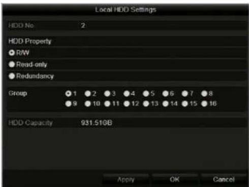
- Click Read-only, click Apply to save the setting, and then click OK.
Note If you want to save files to the HDD, change the property to R/W. If there is only one HDD and it is set to Read-only, the device will not record any files. Only live view mode will be available. If you set the HDD to Read-only while the device is saving files, the filed will be saved to the next R/W HDD or, if there is only one HDD, recording will stop.
Playing Back Video
This chapter contains the following sections:
• Searching and Playing Back Video by Channel, page 68
• Searching and Playing Back Video by Time, page 70
• Searching and Playing Back Video by Event, page 72
• Searching and Playing Back Video by Tag, page 74
• Searching and Playing Back Video by System Log, page 75
- Playback Operations, page 76
Searching and Playing Back Video by Channel
You can play back video recorded on a specific channel. Channel switch is supported.
To play back the last five minutes of video:
- Click a channel in live view mode to display the quick setting toolbar.
-
On the toolbar, click the Instant Playback button 📋. The channel begins playing back video from the last five minutes.
You can use the on-screen playback controls to move backwards or forwards through the video or to pause playback. -
To return to live view mode, click the Exit button .
To search and play back video from the current day or other dates:
- Right-click a channel in live view mode to display the shortcut menu, and then click Today's Video. The playback interface appears.
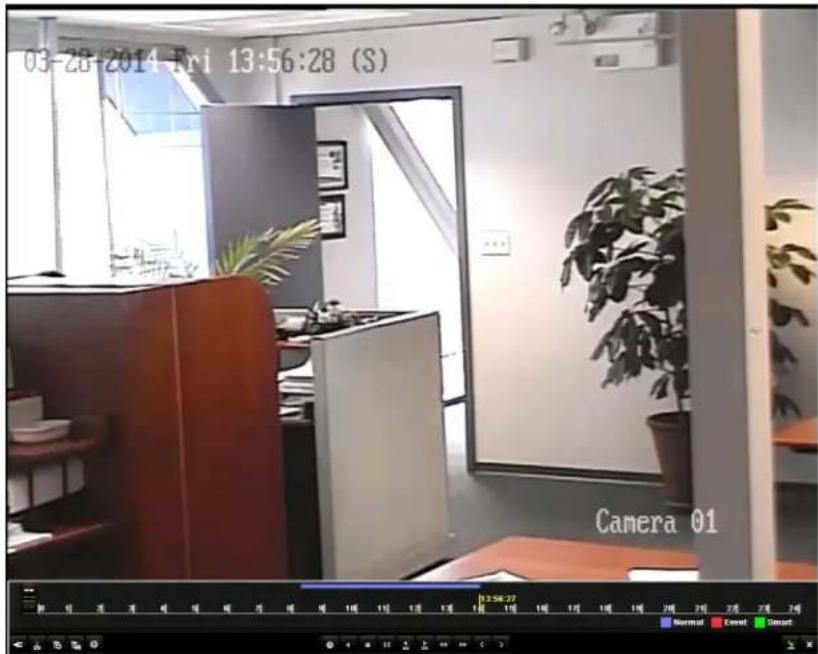
- To display the channel and date selection panel, move the mouse to the right edge of the playback interface.
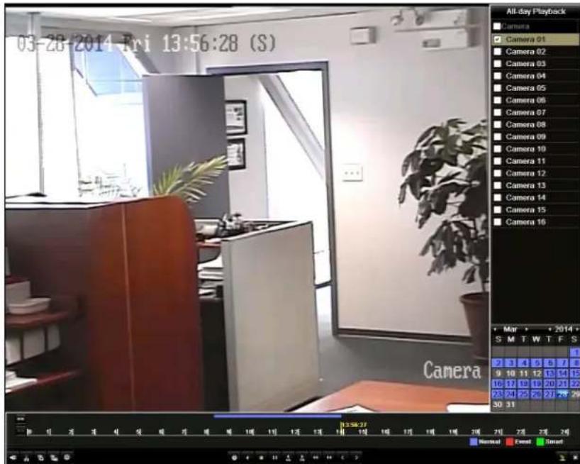
- To switch playback to another channel or to play back video from multiple cameras simultaneously, select one or more additional cameras from the list.
-
To play back video from a different date, double-click the date in the calendar. The dates with recorded video are shown in blue or red. Blue indicates normal recording. Red indicates event recording.
-
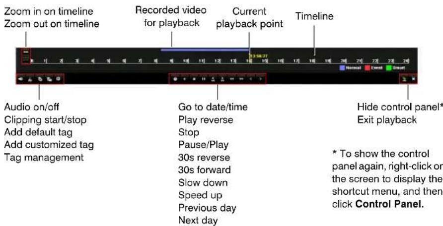
Control playback using the control panel at the bottom of the screen. Drag the yellow indicator to the desired playback point in the timeline.
- To close the playback interface, click the Exit button ✗.
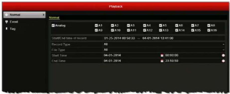
Searching and Playing Back Video by Time
You can search for and play back recorded video by record type, file type, and time. Multi-channel simultaneous playback and channel switch are supported.
To search for and play back video by time:
- Go to Menu > Clip Search > Normal.
-
Under Normal, select the channel(s) you want to search, or click Analog to select all the channels.
-
Configure the following search parameters:
-
Record Select one of the following recording types: Normal, Motion, Alarm, Motion | Alarm, Motion & Alarm, Manual, or All.
- File Type Selection of the following file types: Unlocked, Locked, or All.
- Start T Seleenthedate and time for the start point of the search.
- End Time Select the date and time for the end point of the search.
Note The start and end search points must fall within the range listed next to Start/End time of record.
-
Do one of the following:
-
To view the time ranges and record types of the video matching your search parameters, click Detail. Click Previous or Next to see information for the previous or following day. Click Back to close the window.
- To play back video matching your search parameters from the earliest point, click Playback. The video begins playing in the playback interface.
- To search for a specific video file to play back, click Search. The Search result window opens, displaying a list of search results.
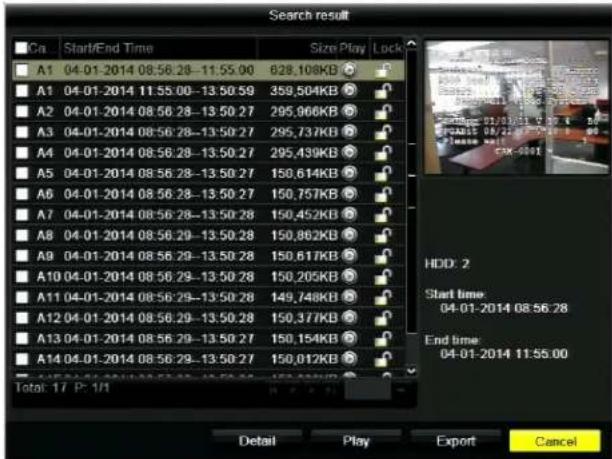
Select the video file that you want to view, and then click Play. The video begins playing in the playback interface.
Searching and Playing Back Video by Event
You can search for and play back video recorded during alarm input and motion detection events. Channel switch is supported. For information on configuring alarm input and motion detection settings, see Configuring Alarms Inputs, page 84, and Configuring Motion Detection Settings, page 89.
To search for and play back video by event:
- Go to Menu > Clip Search > Event.
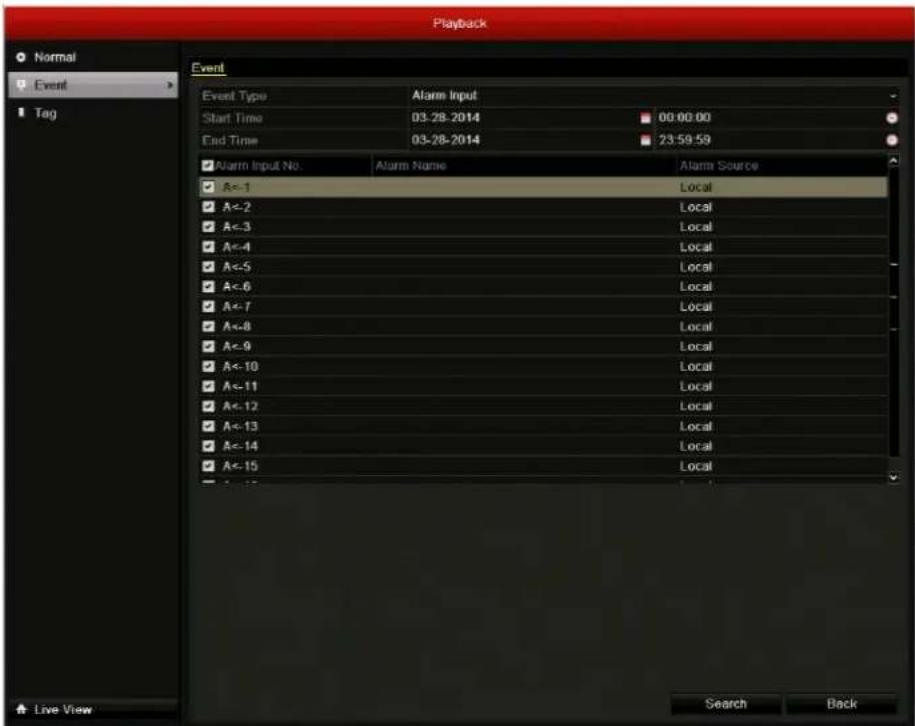
- Under Event, configure the following search parameters:
• Event Select Alarm Input or Motion.
- Start T Seleenthedate and time for the start point of the search.
- End Time Select the date and time for the end point of the search.
-
Do one of the following:
-
If Alarm Input was selected as the event type, select the alarm input(s) you want to search from the list, or click Alarm Input No. to select all the alarm inputs.
-
If Motion was selected as the event type, select the channel(s) you want to search from the list, or click Analog to select all the channels.
-
Click Search. A list of search results is displayed. (If no event recordings were found, the message "No event information found" appears.)
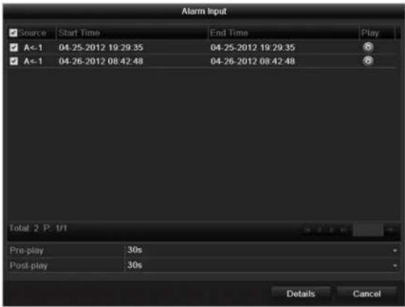
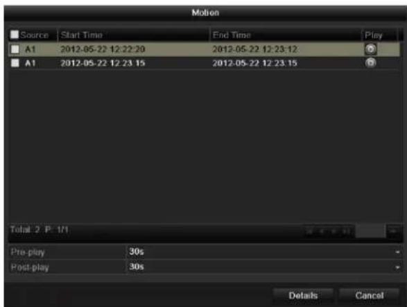
- Select the clips(s) you want to view, and then click the Play button 📋.
If you want, you can adjust the Pre-play and Post-play settings. By default, playback starts 30 seconds before the start of the event and continues 30 seconds past the end of the event. To view the file details (start time, end time, file size), click Details.
Searching and Playing Back Video by Tag
You can search for and play back video that has been previously tagged. For more information, see Working with Tags, page 76.
To search for and play back video by tag:
- Go to Menu > Clip Search > Tag.
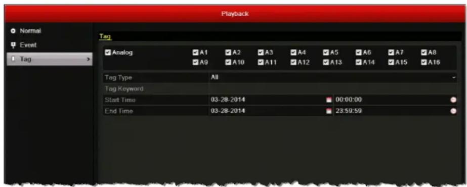
- Under Tag, select the channel(s) you want to search, or click Analog to select all the channels.
-
Configure the following search parameters:
-
Tag T y Select Tag Keyword or All.
- Tag Key tag Keyword was selected as the tag type, enter the tag keyword you want to search for.
- Start T Seleenthedate and time for the start point of the search.
-
E n d T i n Select the date and time for the end point of the search.
-
Click Search. A list of search results is displayed. (If no tags were found, the message "No tag found" appears.)
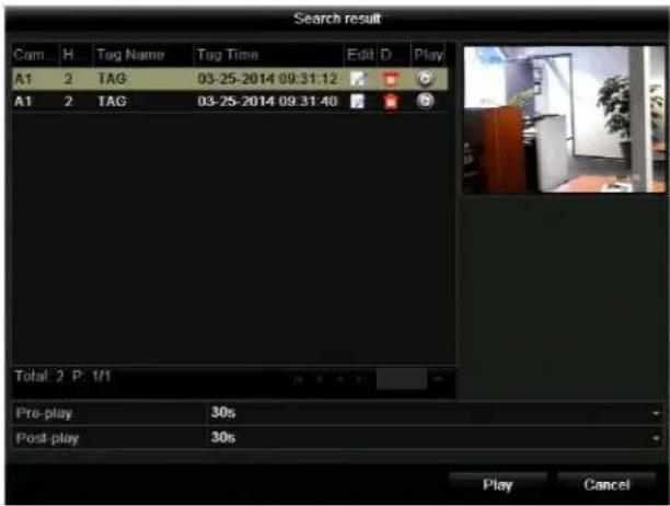
- Select the clips(s) you want to view, and then click the Play button 📋.
- If you want, you can adjust the Pre-play and Post-play settings. By default, playback starts 30 seconds before the tag and continues 30 seconds after the tag.
- To edit the tag name, click the Edit button. Enter a new name in the Tag Name field, and then click OK.
- To delete the tag, click the Delete button.
Searching and Playing Back Video by System Log
See Searching and Exporting Log Files, page 137.
Playback Operations
Creating Video Clips
You can create a customized video clip during playback.
To create a video clip:
- In the playback interface, select the starting point of the clip by using the controls on the playback control panel (for example, drag the yellow indicator to the desired start point in the timeline).
- On the playback control panel, click the Start clipping button to start the clip.
- Click the Stop clipping button to stop the clip.
Working with Tags
You can tag people or items of interest in a video under playback to mark points in the video that you may want to return to later (see Searching and Playing Back Video by Tag, page 74).
To add a default (non-editable) tag:
- In the playback interface, select the point in the video where you want to add a tag by using the controls on the playback control panel (for example, drag the yellow indicator to the desired insertion point in the timeline).
- On the playback control panel, click the Add default tag button 📋.
To add a custom tag:
-
In the playback interface, select the point in the video where you want to add a tag by using the controls on the playback control panel (for example, drag the yellow indicator to the desired insertion point in the timeline).
-
On the playback control panel, click the Add custom tag button 📋. The Add Tag window opens.
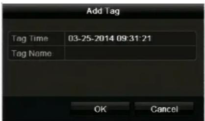
- In the Tag Name field, enter a unique tag name or keyword, and then click OK.
To manage tags:
- In the playback interface, on the playback control panel, click the The Tag Management window opens.
Manage tags button 🙏.
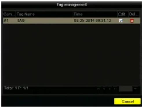
- Do one of the following:
- To edit a tag name, select the tag you want to edit, and then click the Edit button. In the Edit Tag window, enter a new name in the Tag Name field, and then click OK.
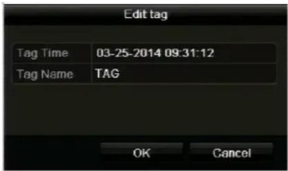
- To delete a tag, select the tag you want to delete, and then click the
Delete button

Using Digital Zoom
You can use the digital zoom function during playback to enlarge an area of the on-screen image.
To use digital zoom during playback:
- In the playback interface, right-click on the screen to display the shortcut menu, and then click Digital Zoom.
The picture on the screen is magnified by 4 times and the normal screen view appears as an inset window in the lower right corner of the screen. The magnified area is indicated by a red frame.
- In the inset window, drag the red frame to the area of the screen you want to zoom in on.
- To exit digital zoom mode, right-click anywhere on the screen.
Using Smart Search
You can use the smart search function during all-day playback (See Searching and Playing Back Video by Channel, page 68) to find motion detection events that have occurred in a specific area in a scene.
To use smart search:
-
In the playback interface, right-click on the screen to display the shortcut menu, and then click Smart Search.
-
Set the smart search area.
• To set a portion of the screen as the smart search area, drag the mouse over the area of the scene you want to search. You can set multiple smart search areas.
• To set the whole screen as the smart search area, click the Full Screen Detection button on the on-screen toolbar.
The smart search area is indicated by a red grid.
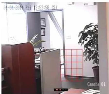
- Click the Search button ▶ on the on-screen toolbar. The search results are displayed over the timeline as a series of green bars.
- Click the Next smart search result > and Previous smart search result < buttons to quickly go to the video locations where motion was detected in the smart search area.
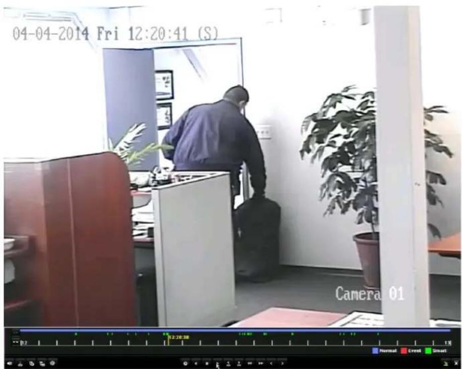
Exporting Video
This chapter contains the following sections:
- Exporting Recorded Video Files, page 79
- Exporting Video Clips, page 81
Exporting Recorded Video Files
You can export recorded video to a USB flash drive or other external storage device. You can search for video by date and time or by event (motion detection and/or alarm).
To export recorded video files:
- Insert a USB flash drive or other external storage device into the USB port on the front of the DVR.
- Go to Menu > Clip Search > Normal.
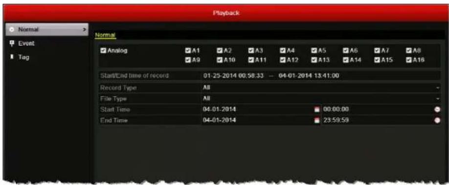
-
On the Normal page, under Normal, select the channel(s) you want to search, or click Analog to select all the channels.
-
Configure the following search parameters:
-
R e c o r dSelect group of the following recording types: Normal, Motion, Alarm, Motion | Alarm, Motion & Alarm, Manual, or All.
- File Type Selection of the following file types: Unlocked, Locked or All.
- Start T Seleenthedate and time for the start point of the search.
- End Time Select the date and time for the end point of the search.
Note The start and end search points must fall within the range listed next to Start/End time of record.
- Click Search. The Search result window opens, displaying a list of search results.
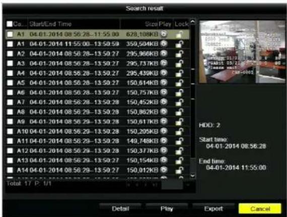
- Select the file(s) that you want to export, and then click Export. The Export window opens.
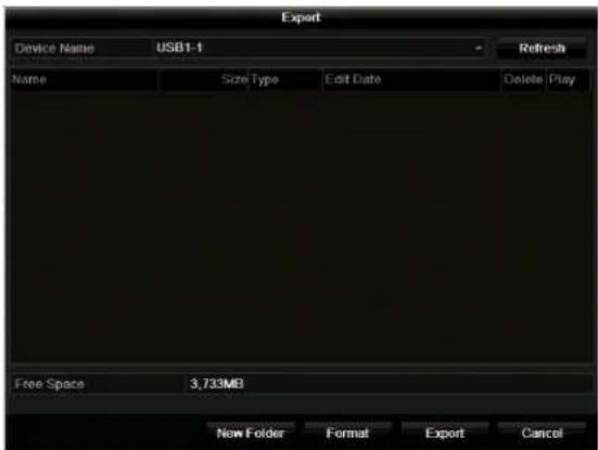
- Click Export to save the file(s) to the storage device.
Exporting Video Clips
You can export a customized video clip created during playback.
To export customized video clips:
- During video playback, use the clipping start/stop function on the playback control panel to create one or more video clips. See Creating Video Clips, page 76.
- Close the playback interface. The following message appears: "There are some video clips to be saved. Do you want to save them now?" Click Yes. The Export window opens.
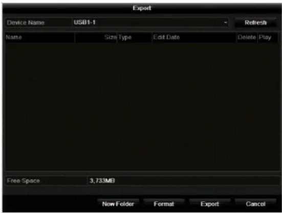
- If you have not already done so, insert a USB flash drive or other external storage device into the USB port on the DVR, and then click Refresh.
- Click Export to save the video clip(s) to the storage device.
8
Configuring Alarm Settings
This chapter contains the following sections:
- Configuring Alarms Inputs, page 84
- Configuring Alarm Outputs, page 87
- Configuring Motion Detection Settings, page 89
- Configuring Video Tampering Detection Settings, page 92
- Configuring Video Loss Detection Settings, page 94
- Configuring Exception Settings, page 96
- Configuring Email Settings, page 97
- Configuring Remote Alarm Host Settings, page 99
Configuring Alarms Inputs
This section describes how to set the alarm input (sensor) type and handling properties. You can set up the DVR to trigger one or more of the following alarm responses when a sensor alarm event is detected:
| Video Recording | Video begins recording on the triggered channel. |
| Full Screen Monitoring | The monitor displays full screen video from the triggered channel. When multiple channels are triggered simultaneously, the images switch at regular intervals (the default dwell time is 10 seconds). |
| Audio Alarms | An audible beep sounds. |
| Surveillance Center Notification | A signal is sent to a remote alarm host.See Configuring Remote Alarm Host Settings, page 99. |
| Email Notification | An email containing the event details is sent to one or more recipients. See Configuring Email Settings, page 97. |
| Alarm Output | A signal is sent to an external alarm.See Configuring Alarm Outputs, page 87. |
To configure alarm input settings:
- Go to Menu > Settings > Alarm > Alarm Input.
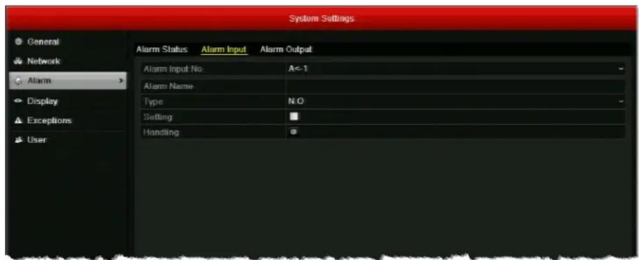
- Select the alarm input you want to configure from the Alarm Input No. drop-down list.
- If you want, in the Alarm Name field, enter a descriptive name for the alarm input.
-
Next to Type, select your alarm input type:
-
N. The alarm input is normally open. If it is closed, an alarm signal is generated.
• N . The alarm input is normally closed. If it is opened, an alarm signal is generated. -
Select the Setting check box to enable the alarm input.
-
Click the Handling button 🤗 to set up the alarm response actions. The Handling window opens.
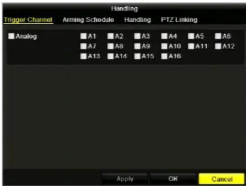
a. Under Trigger Channel, select the channel(s) you want to begin full-screen monitoring or recording video with when the alarm input generates an alarm signal, or click Analog to select all the channels, and then click Apply to save your settings.
Note To automatically start recording video on the channel when an alarm input event is detected, you must set the recording schedule to Alarm, Motion | Alarm, or Motion & Alarm. See Configuring a Record Schedule, page 56.
b. Click the Arming Schedule tab to set the arming schedule of the alarm input. You can set up to eight time periods per day (the time periods cannot repeat or overlap). To copy the arming schedule to other days of the week, click Copy. Click Apply to save your settings.
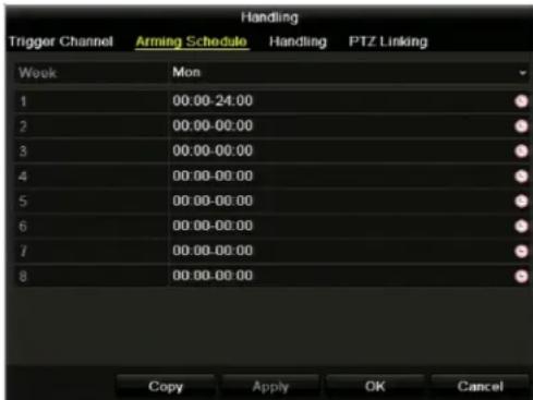
c. Click the Handling tab to set the action(s) you want to occur when the alarm input generates an alarm signal. Select the check box corresponding to the action(s) you want to enable, and then click Apply to save your settings.
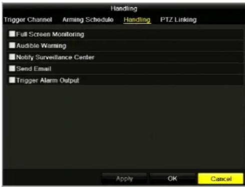
d. If applicable, select the PTZ Linking tab to set the PTZ linkage of the alarm input. Select the preset, patrol, or pattern you want to call when the alarm input generates an alarm signal, click Apply to save your settings, and then click OK to close the window.
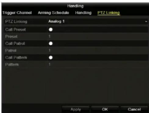
- To copy these settings to one or more additional alarm inputs, click Copy to open the Copy Alarm Input to window, select the alarm input(s) you want to copy the settings to, or click Alarm Input No. to copy the settings to all alarm inputs, and then click OK.
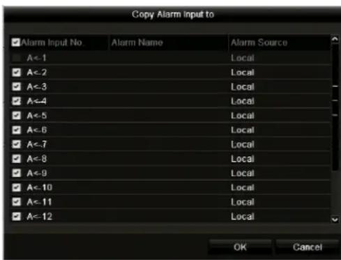
- Click Apply to save your settings.
Configuring Alarm Outputs
This section describes how to set the dwell time and handling properties of alarm outputs.
To configure alarm output settings:
- Go to Menu > Settings > Alarm > Alarm Output.
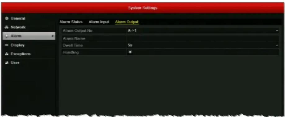
- Select the alarm output you want to configure from the Alarm Output No. drop-down list.
- If you want, in the Alarm Name field, enter a descriptive name for the alarm output.
- Next to Dwell Time, set the alarm output dwell time in seconds. Select a value between 5 seconds and 600 seconds (10 minutes) or select Manually Clear.
Note If the alarm output dwell time is set to Manually Clear, you must go to Menu > Manual > Alarm to clear the alarm. Select the alarm output(s) you want to clear, and then click Clear (or click Clear All to clear all alarm outputs).
- Click the Handling button 🙏 to set the arming schedule of the alarm output. You can set up to eight time periods per day (the time periods cannot repeat or overlap). To copy the arming schedule to other days of the week, click Copy. Click Apply to save your settings.
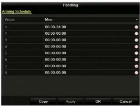
- To copy these settings to one or more additional alarm outputs, click Copy to open the Copy Alarm Output to window, select the alarm output(s) you want to copy the settings to, or click Alarm Output No. to copy the settings to all alarm outputs, and then click OK.
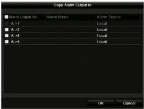
- Click Apply to save your settings.
Configuring Motion Detection Settings
You can set up the DVR to trigger one or more of the following alarm responses when motion is detected in a restricted area:
| Video Recording | Video begins recording on the triggered channel. |
| Full Screen Monitoring | The monitor displays full screen video from the triggered channel. When multiple channels are triggered simultaneously, the images switch at regular intervals (the default dwell time is 10 seconds). |
| Audio Alarms | An audible beep sounds. |
| Surveillance Center Notification | A signal is sent to a remote alarm host.See Configuring Remote Alarm Host Settings, page 99. |
| Email Notification | An email containing the event details is sent to one or more recipients. See Configuring Email Settings, page 97. |
| Alarm Output | A signal is sent to an external alarm.See Configuring Alarm Outputs, page 87. |
To configure motion detection settings:
- Go to Menu > Camera > Motion.
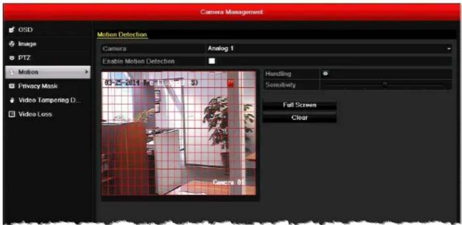
- Select the camera you want to configure motion detection settings for by clicking a number in the Camera drop-down list.
- Select the Enable Motion Detection check box.
-
The motion detection area (indicated by a red grid) covers the entire screen by default. To create a smaller motion detection area, click Clear, and then drag the mouse over the area you want to detect motion in on the preview window.
-
Drag the Sensitivity slider to set the desired sensitivity level (7 levels configurable).
- Click the Handling button 🤒 to set up the alarm response actions. The Handling window opens.
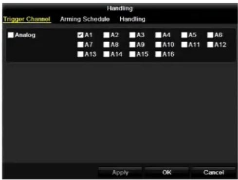
a. Under Trigger Channel, select the channel(s) you want to begin full-screen monitoring or recording video with when motion is detected, or click Analog to select all the channels, and then click Apply to save your settings.
Note To automatically start recording video on the channel when motion is detected, you must set the recording schedule to Motion, Motion | Alarm, or Motion & Alarm. See Configuring a Record Schedule, page 56.
b. Click the Arming Schedule tab to set the arming schedule. You can set up to eight time periods per day (the time periods cannot repeat or overlap). To copy the arming schedule to other days of the week, click Copy. Click Apply to save your settings.
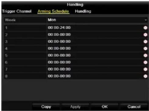
c. Click the Handling tab to set the action(s) you want to occur when motion is detected. Select the check box corresponding to the action(s) you want to enable, click Apply to save your settings, and then click OK to close the window.
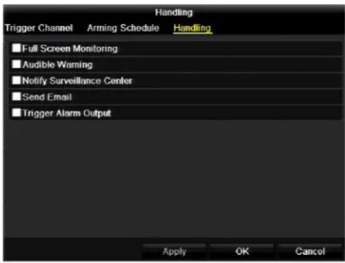
- To copy these settings to one or more additional channels, click Copy to open the Copy to window, select the channel(s) you want to copy the settings to, or click Analog to copy the settings to all channels, and then click OK.
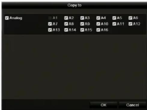
- Click Apply to save your settings.
Configuring Video Tampering Detection Settings
You can set up the DVR to trigger one or more of the following alarm responses when a video tampering event is detected (for example, the lens is covered):
| Full Screen Monitoring | The monitor displays full screen video from the triggered channel. When multiple channels are triggered simultaneously, the images switch at regular intervals (the default dwell time is 10 seconds). |
| Audio Alarms | An audible beep sounds. |
| Surveillance Center Notification | A signal is sent to a remote alarm host.See Configuring Remote Alarm Host Settings, page 99. |
| Email Notification | An email containing the event details is sent to one or more recipients. See Configuring Email Settings, page 97. |
| Alarm Output | A signal is sent to an external alarm.See Configuring Alarm Outputs, page 87. |
To configure video tampering detection settings:
- Go to Menu > Camera > Video Tampering Detection.
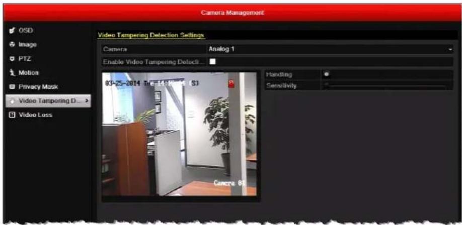
- Select the camera you want to configure video tampering detection settings for by clicking a number in the Camera drop-down list.
- Select the Enable Video Tampering Detection check box.
- Click the Handling button 🙏 to set up the alarm response actions. The Handling window opens.
a. Under Arming Schedule, you can set up to eight time periods per day (the time periods cannot repeat or overlap). To copy the arming schedule to other days of the week, click Copy. Click Apply to save your settings.
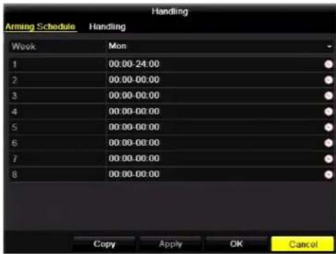
b. Click the Handling tab to set the action(s) you want to occur when video tampering is detected. Select the check box corresponding to the action(s) you want to enable, click Apply to save your settings, and then click OK to close the window.
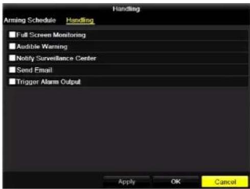
- Drag the Sensitivity slider to set the desired sensitivity level (3 levels configurable).
- To copy these settings to one or more additional channels, click Copy to open the Copy to window, select the channel(s) you want to copy the settings to, or click Analog to copy the settings to all channels, and then click OK.
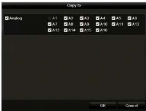
- Click Apply to save your settings.
Configuring Video Loss Detection Settings
You can set up the DVR to trigger one or more of the following alarm responses when a video loss event is detected:
Full Screen Monitoring
The monitor displays full screen video from the triggered channel. When multiple channels are triggered simultaneously, the images switch at regular intervals (the default dwell time is 10 seconds).
Audio Alarms
An audible beep sounds.
Surveillance Center Notification
A signal is sent to a remote alarm host. See Configuring Remote Alarm Host Settings, page 99.
Email Notification
An email containing the event details is sent to one or more recipients. See Configuring Email Settings, page 97.
Alarm Output
A signal is sent to an external alarm. See Configuring Alarm Outputs, page 87.
To configure video loss settings:
- Go to Menu > Camera > Video Loss.
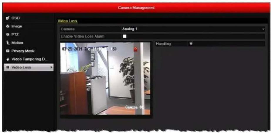
- Select the camera you want to configure video tampering detection settings for by clicking a number in the Camera drop-down list.
- Select the Enable Video Loss Alarm check box.
- Click the Handling button 🤒 to set up the alarm response actions. The Handling window opens.
a. Under Arming Schedule, you can set up to eight time periods per day (the time periods cannot repeat or overlap). To copy the arming schedule to other days of the week, click Copy. Click Apply to save your settings.

b. Click the Handling tab to set the action(s) you want to occur when video loss is detected. Select the check box corresponding to the action(s) you want to enable, click Apply to save your settings, and then click OK to close the window.
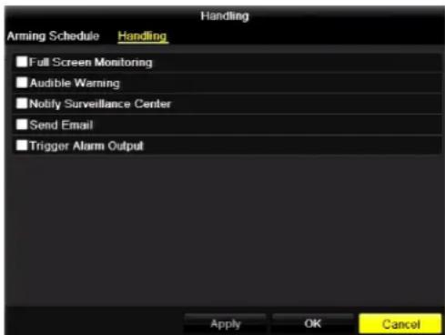
- To copy these settings to one or more additional channels, click Copy to open the Copy to window, select the channel(s) you want to copy the settings to, or click Analog to copy the settings to all channels, and then click OK.
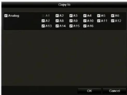
- Click Apply to save your settings.
Configuring Exception Settings
In addition to configuring alarms for sensor, motion detection, video tampering detection, and video loss events, you can also configure alarms for device exceptions, such as hard drive errors and network problems.
To configure exception settings:
- Go to Menu > Settings > Exceptions.
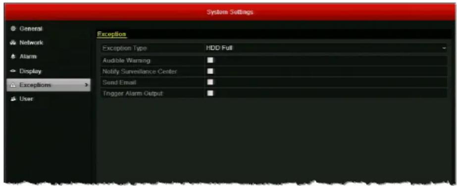
-
In the Exception Type drop-down list, select one of the following exceptions, or select All:
-
HDD Full The DVR's hard disk drive (HDD) is full.
- HDD Error The HDD has experienced a writing or formatting error.
• Network Disconnected The network cable is disconnected. - I P C o n f l i There is and IP address conflict.
- Illegal Login An incorrect user name or password was entered.
- Input/Output Video Standard Mismatch Input/output video standards do not match.
-
Record Ex There is no space to save a recorded file.
-
Select one or more of the following alarm responses for the exception(s):
• Audible Warning
- Notify Surveillance Center (Not available for Network Disconnected or IP Conflicted)
- Send Email
- Trigger Alarm Output
- Click Apply to save your settings.
Configuring Email Settings
You can configure email settings for sending notification messages when an alarm event or a device exception is detected.
Note It is recommended that you set up a web-based email account for use only with the DVR.
Before you begin, ensure that the DVR is connected to a local area network (LAN) that maintains an SMTP mail server (see Configuring General Network Settings, page 102). The network must also be connected to a local intranet or the Internet, depending on the location of the email accounts you want to notify.
To configure email settings:
- Go to Menu > Settings > Network > Email.
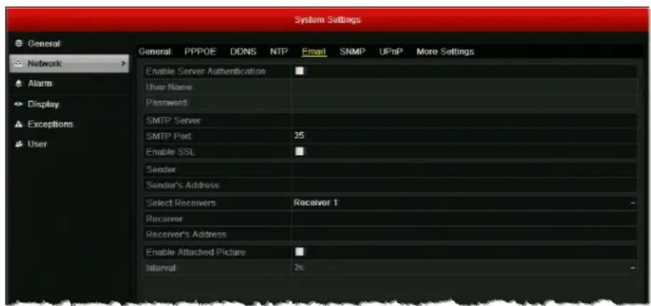
-
Configure the following settings:
-
Enable Server Authentication
(Optional) Select the check box to enable server authentication. Clear the check box to disable it. - User Name eSender's email address. For example: my.hrgx.dvr@gmail.com
- Password of sender's email account.
- SMTP Server SMTP server address of sender's email account. For example: smtp.gmail.com
- SMTP Port The default TCP/IP port used for SMTP is 25.
- Enable SSL Select the check box to enable SSL (if required by SMTP server). Clear the check box to disable it.
| • Sender | Enter the name of the sender.For example: My HRGX DVR |
| • Sender's Address | Enter the email address of the sender.For example: my.hrgx.dvr@gmail.com |
| • Select Receivers | Select the receiver to be notified. You can configure up to 3 receivers. |
| • Receiver | Enter the name of the receiver you have selected. |
| • Receiver's Address | Enter the email address of the receiver you have selected. |
| • Enable Attached Picture | Select the check box to attach alarm images to notification email. |
| • Interval | Sets the time between actions of sending attached pictures.Select a value between |
-
Click Apply to save your settings.
-
If you want, click Test to send a test email. A message will appear telling you whether the test succeeded or failed. If the test email fails, you will be prompted to recheck the email and network settings.
Configuring Remote Alarm Host Settings
You can configure a remote alarm host to receive a notification message from the DVR when an alarm event or a device exception is detected. The remote alarm host must be a PC with Client Management System (CMS) software installed on it (such as Multi-Site 4200).
To configure a remote alarm host:
- Go to Menu > Settings > Network > More Settings.
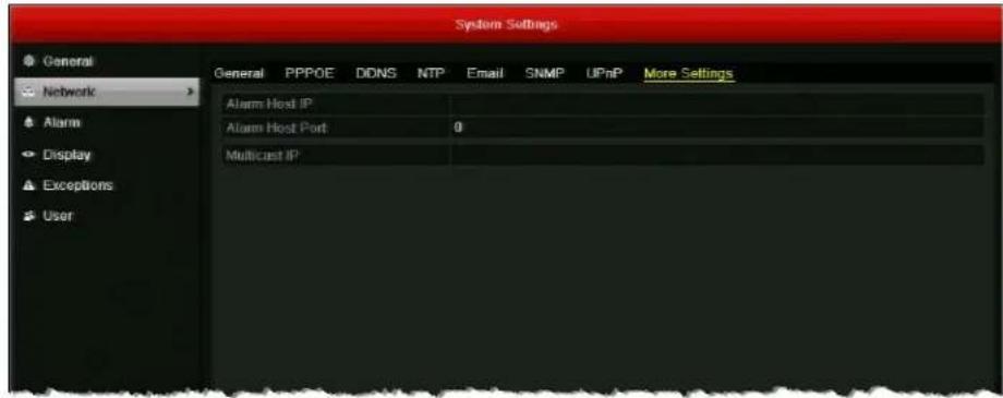
- In the Alarm Host IP and Alarm Host Port fields, enter the IP address and port of the remote alarm host.
The Alarm Host IP refers to the IP address of the remote PC on which Multi-Site 4200 or other CMS software is installed. The Alarm Host Port must be the same as the alarm monitoring port configured in the software (the default port is 7200).
- Click Apply to save your settings.
9
Configuring Network Settings
This chapter contains the following sections:
- Configuring General Network Settings, page 102
- Configuring Advanced Network Settings, page 103
• Managing Network Settings, page 109
Configuring General Network Settings
This section describes how to configure your DVR's general network settings. Your network settings must be properly configured before you operate the DVR over a network.
To configure general network settings:
- Go to Menu > Settings > Network > General.
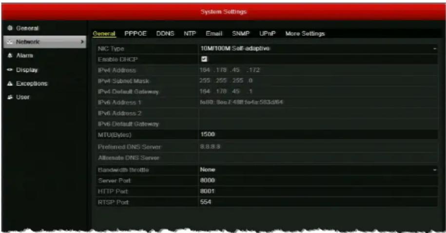
-
Configure the following settings:
-
N I C T y p eSelect your network interface controller type from the list.
- Enable DDHCPCs enabled by default. To disable it, clear the check box.
- I P v 4 / I P W DICCP as disabled, Danually enter your DVR's network settings.
- M T U ( B y t Selecta value between 500 and 1500. Default setting is 1500.
- Bandwidth Throttle Select a value between 1Mbps and 30Mbps or select None.
- Server P Used for remote client software access. Default setting is 8000.
- HTTP Port Used for remote browser access. Default setting is 8001.
-
RT S P P o Used for multimedia playback. Default setting is 554.
-
Click Apply to save your settings.
Configuring Advanced Network Settings
This section describes how to configure PPPoE, DDNS, NTP, SNMP, UPnP, Multicast, RTSP, server port, and HTTP port settings.
Note Instructions for configuring email and remote alarm host settings are found in Chapter 8, Configuring Alarm Settings.
Configuring PPPoE Settings
The HRGX supports Point-to-Point Protocol over Ethernet (PPPoE) network connections.
To configure PPPoE settings:
- Go to Menu > Settings > Network > PPPOE.
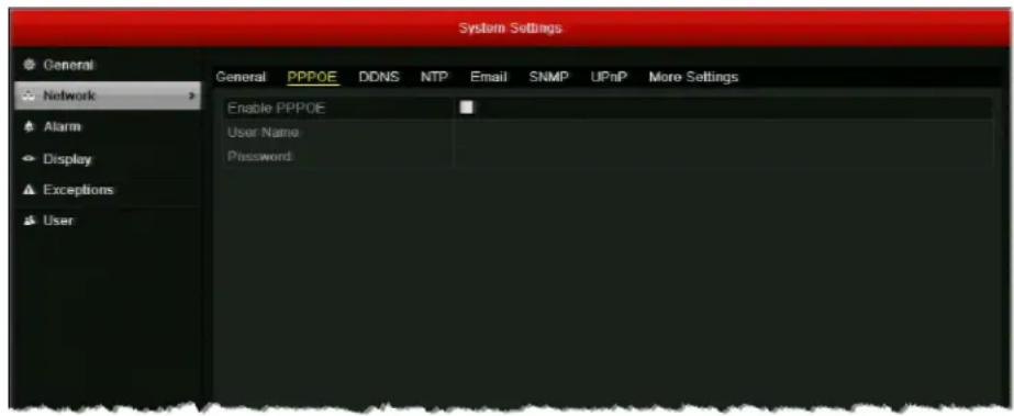
- Select the Enable PPPOE check box to enable a PPPoE network connection.
- In the User Name and Password fields, enter the user name and password assigned by your Internet service provider for PPPoE access.
- Click Apply to save your settings, and then restart the DVR for the change to take effect. The PPPoE connection will initiate automatically.
To view PPPoE connection information, go to Menu > Maintenance > System Info > Network.
Configuring DDNS Settings
If your device is set to use PPPoE as its default network connection, you can use Dynamic DNS (DDNS) for network access. Prior registration with your Internet service provider is required before configuring the system to use DDNS.
To configure DDNS settings:
- Go to Menu > Settings > Network > DDNS.
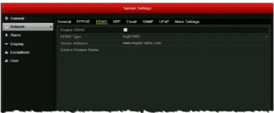
- Select the Enable DDNS check box to enable DDNS functionality.
- Set DDNS Type to DynDNS or hrgDDNS (default).
-
In the Server Address field, enter the server address of the DDNS service.
-
If you selected DynDNS as the DDNS type, enter members.dyndns.org.
-
If you selected hrgDDNS as the DDNS type, enter www.hrgdvr-ddns.com.
-
In the Device Domain Name field, do one of the following:
-
If you selected DynDNS as the DDNS type, enter the domain name (hostname) that you created on the DynDNS website (for example, hrgx-sample-dvr.dyndns-server.com).
-
If you selected hrgDDNS as the DDNS type, enter the domain name you want to use for the DVR. The domain name must begin with a lowercase letter and cannot contain any special characters other than hyphens (-).
-
Click Apply to save your settings.
Configuring NTP Server Settings
You can configure a Network Time Protocol (NTP) server to ensure the accuracy of the system date and time.
To configure NTP settings:
- Go to Menu > Settings > Network > NTP.
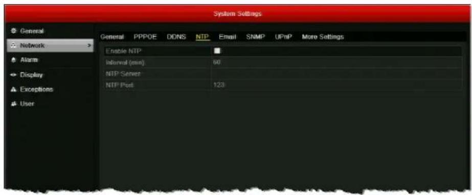
-
Select the Enable NTP check box to enable time synchronization with an NTP server.
-
Configure the following settings:
- Interval (Sets the time interval, in minutes, between two synchronizing actions with the NTP server. Select a value from 1 to 10080. The default value is 60.
- N T P S e r v e Enter the IP address of the NTP server.
- N T P P o r t Enter the port of the NTP server.
- Click Apply to save your settings.
Configuring SNMP Settings
You can use Simple Network Management Protocol (SNMP) to obtain device status and parameters-related information. You will need to install SNMP software to receive device information via SNMP.
To configure SNMP settings:
- Go to Menu > Settings > Network > SNMP.
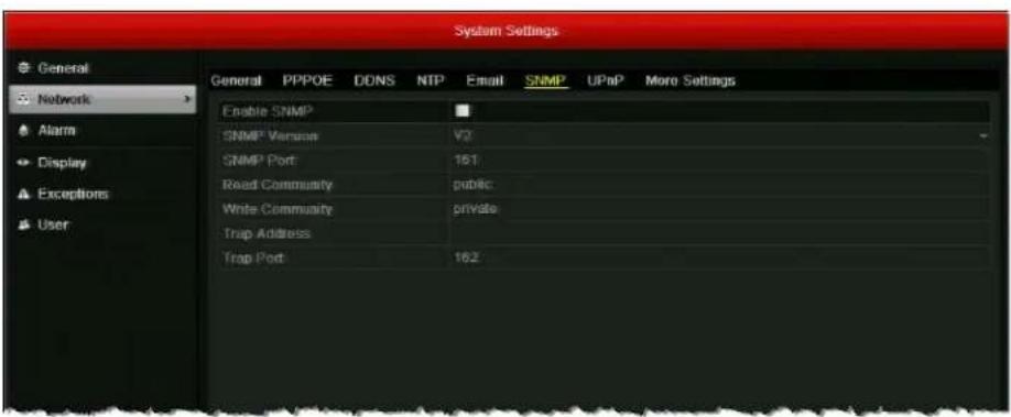
- Select the Enable SNMP check box to enable this feature.
- Configure the following settings: SNMP Version, SNMP Port, Read Community, Write Community, Trap Address, and Trap Port.
Note By setting the trap address, you are allowing the device to send alarm event and device exception notification messages to the surveillance center.
- Click Apply to save your settings.
Configuring UPnP Settings
Universal Plug and Play (UPnP) lets the DVR to seamlessly discover other devices on the network and establish functional network services for data sharing, and communications. For example, if you want to enable a fast WAN connection via a router, you should configure UPnP on the DVR.
To enable UPnP on the DVR, you will first need to enable UPnP on the router that your device is connected to. When the network working mode of the DVR is set as multi-address, the Default Route should be in the same network segment as the LAN IP address of the router.
To configure UPnP settings:
- Go to Menu > Settings > Network > UPnP.
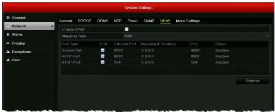
- Select the Enable UPnP check box to enable Universal Plug and Play on your DVR.
- Set Mapping Type to Auto or Manual.
When Auto is selected, the mapping ports are automatically assigned by the router. When Manual is selected, the mapping ports must be configured manually.
- If the mapping type is set to Manual, click the Edit button ☐ to manually configure the external port numbers for Server Port, HTTP Port, and RTSP Port.
- To view the latest status of the port mapping, click Refresh.
- Click Apply to save your settings.
Configuring Multicast Settings
Multicast allows multiple simultaneous views of the same live video stream over a network.
To configure multicast:
- Go to Menu > Settings > Network > More Settings.
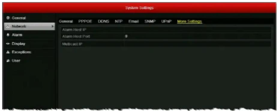
- In the Multicast IP field, enter a multicast address for the DVR. It is recommended that you use an IP address in the range of 239.252.0.0 to 239.255.255.255.
Note When adding a device using Multi-Site 4200 or other CMS software, the multicast address must be the same as the multicast IP of the DVR.
- Click Apply to save your settings.
Managing Network Settings
This section describes how to monitor real-time network traffic data and network statistics, test network delay and packet loss, and export a network packet.
Monitoring Network Traffic and Bandwidth
You can view real-time information about the network, including linking status, MTU, sending/receiving rate, and bandwidth statistics for remote live view, remote playback, and net total idle.
To view network traffic data:
• G o t o Menu > Maintenance > Net Detect > Traffic.
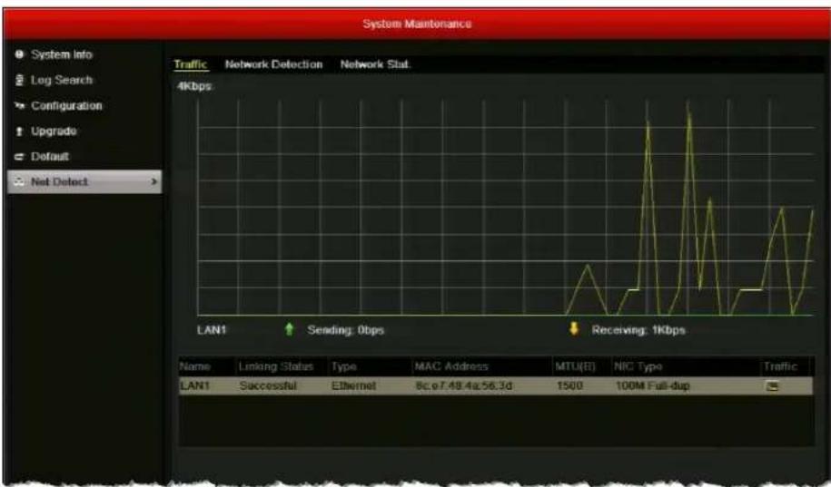
You can view the sending and receiving rate. You can also view the linking status and MTU size below the graph. The traffic data is refreshed every 1 second.
To view network bandwidth data:
- Go to Menu > Maintenance > Net Detect > Network Stat.
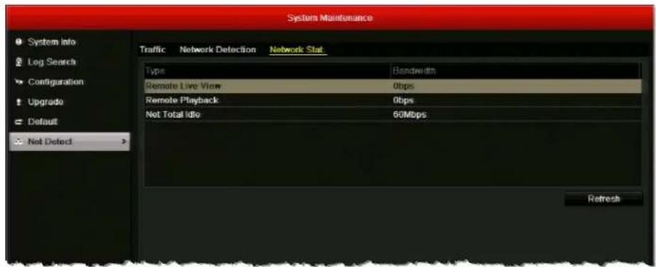
Bandwidth information for remote live view, remote playback, and net total idle is displayed.
- Click Refresh to view the latest bandwidth statistics.
Testing Network Delay and Traffic Loss
You can test network delay and traffic loss and check whether the network is operating normally.
To test network delay and traffic loss:
- Go to Menu > Maintenance > Net Detect > Network Detection.
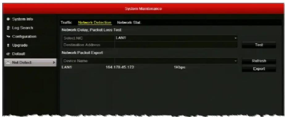
- Under Network Delay, Packet Loss Test, in the Destination Address field, enter the IP address of the packet destination.
- Click Test button to start testing network delay and packet loss. A message will appear telling you whether the test succeeded or failed.
To view network status:
- Go to Menu > Maintenance > Net Detect > Network Detection.
- Click Status to check the network status. If the network is operating normally, the message "Network status is normal" appears. If the network is not operating normally, you can click Network to review and edit your network settings.
Exporting Network Packet
You can export a network data packet to a USB flash drive or other external storage device.
To export a network packet:
- Go to Menu > Maintenance > Net Detect > Network Detection.

- Under Network Packet Export, select your external storage device from the Device Name drop-down list. If your device is not displayed, click Refresh to refresh the list.
- Click Export.
- After the export process is complete, click OK. You can export up to 1 MB of data each time.
10
Configuring HDD Settings
This chapter contains the following sections:
• Viewing HDD Status, page 114
- Adding a Network HDD, page 115
- Configuring HDD Groups, page 117
- Configuring Recording Quotas, page 119
- Configuring S.M.A.R.T. Testing, page 120
• Detecting Bad Sectors, page 121
- Configuring HDD Alarms, page 122
Viewing HDD Status
You can check the status of the hard disk drive(s) at any time.
To view the status of an HDD:
- Go to Menu > HDD > General.
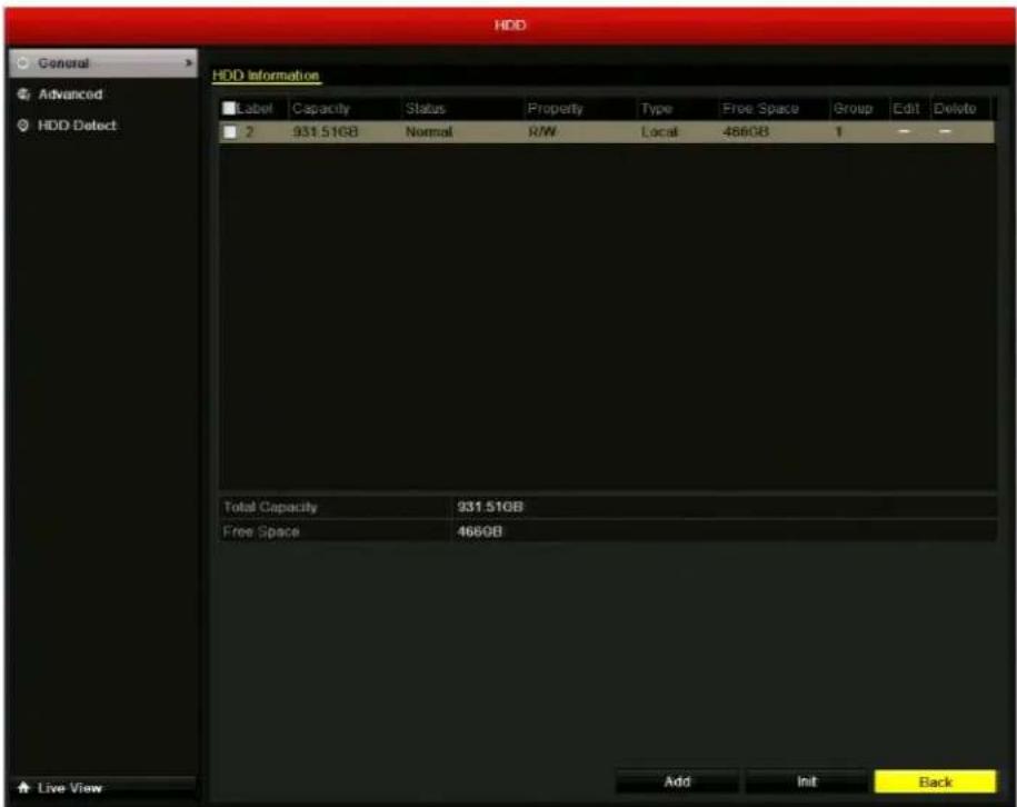
- Under HDD Information, the status of each installed HDD is displayed. If the status of the HDD is listed as Normal or Sleeping, then the HDD is working correctly. If the status is listed as Uninitialized or Abnormal, initialize the HDD (select the HDD and click Init. This will erase all data on the hard disk.). If the initialization fails, replace the HDD.
You can also view the HDD status in the System Maintenance menu. See Viewing System Information, page 134.
Adding a Network HDD
To increase storage capacity you can add a connected NAS (Network-Attached Storage) device or a SAN (Storage Area Network) device to the DVR as a network HDD. You can add up to 8 NAS devices or 7 NAS devices + 1 SAN device.
To add a network HDD:
- Go to Menu > HDD > General.
- Click Add to open the Add NetHDD window.
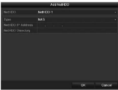
- In the NetHDD list, select the NetHDD you want to add.
- Set the Type to NAS or IP SAN.
- In the NetHDD IP Address field, enter the IP address of the NAS or SAN device.
- Do one of the following:
- For NAS, enter the directory of the NAS disk in the NetHDD Directory field (for example, /dvr/9000).
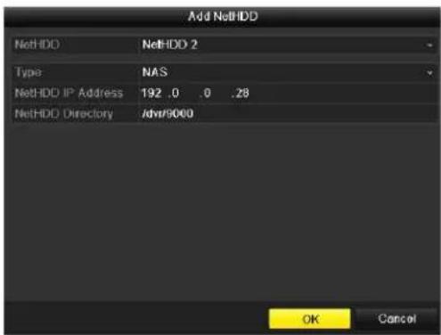
- For SAN, click Search to display a list of available SAN disks on the network, and then select a disk from the list. The directory of the selected disk populates the NetHDD Directory field.
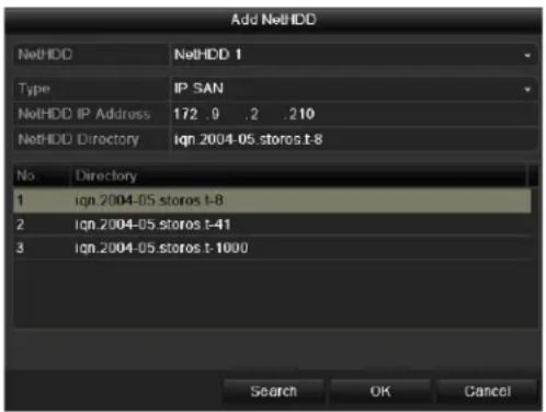
- Click OK to add the disk as the selected network HDD. The newly added network HDD is displayed in the lists of HDDs on the General page.
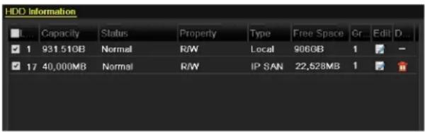
- If the status of the newly added network HDD shows as Uninitialized, select the HDD, and then click Init to initialize the HDD. The HDD must be initialized before it can be used.
To delete a network HDD:
- In Menu > HDD > General, select the HDD you want to delete from the list of HDDs, and then click the Delete button
Configuring HDD Groups
You can manage multiple HDDs in groups. After you have set up an HDD group, you can set the property of an HDD to R/W, Read-only, or Redundancy.
To set up an HDD group:
- Go to Menu > HDD > Advanced.
- Under Storage Mode, set the Mode to Group, and then click Apply.
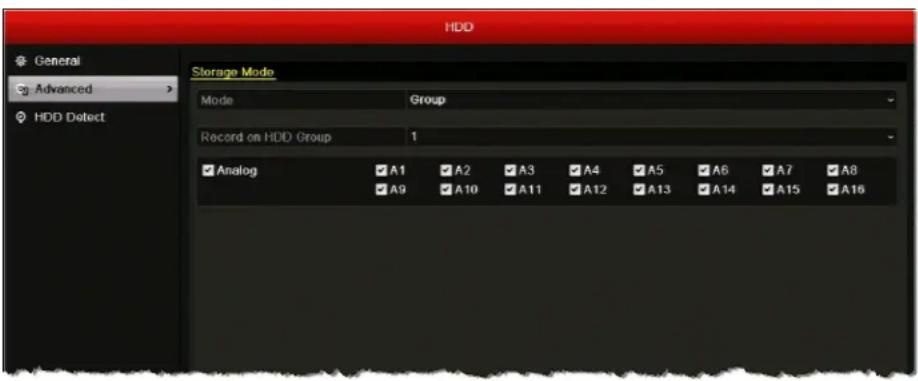
- Restart the DVR for the change to take effect.
- Go to Menu > HDD > General.
- Select an HDD from the list, and then click the Edit button to open the Local HDD Settings window.
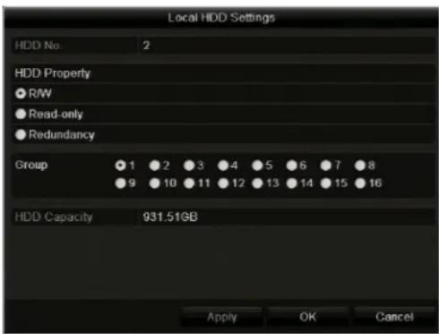
- If you want to change the HDD property, under HDD Property, select one of the following settings:
• R/W Read/write. The default setting.
- R e a d - o n l When the HDD is set to read-only, the recorded files are not overwritten when the HDD becomes full in overwrite recording mode.
- Redundancy When the HDD is set to redundancy, video can be recorded both onto the redundancy HDD and the R/W HDD simultaneously for additional security and reliability.
- In the Group area, select a group number for the HDD group.
- Click Apply to save your settings, click Yes to confirm, and then click OK to close the window.
Configuring Recording Quotas
You can configure recording quotas for individual cameras. By setting a quota, you limit the amount of HDD capacity used for storing recorded video from that particular camera. Otherwise, all cameras will use the total capacity of the HDD for recording.
To configure a recording quota:
- Go to Menu > HDD > Advanced.
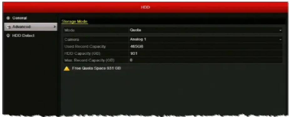
- Under Storage Mode, set the Mode to Quota.
- In the Camera list, select the camera you want to configure a recording quota for.
- In the Max. Record Capacity (GB) field, enter the maximum storage limit for the camera (in gigabytes). If the value is left as "0", then all cameras will use the total capacity of the HDD for recording.
- To copy these settings to one or more additional cameras, click Copy to open the Copy to window, select the camera(s) you want to copy the settings to, or click Analog to copy the settings to all cameras, and then click OK.
- Click Apply to save your settings.
- Restart the DVR for the change to take effect.
Configuring S.M.A.R.T. Testing
You can set up the hard disk drive to perform a series of self-tests using S.M.A.R.T.
(Self-Monitoring, Analysis, and Reporting Technology) to determine the overall health of the HDD and identify potential issues.
To set up a S.M.A.R.T test:
- Go to Menu > HDD > HDD Detect > S.M.A.R.T. Settings.
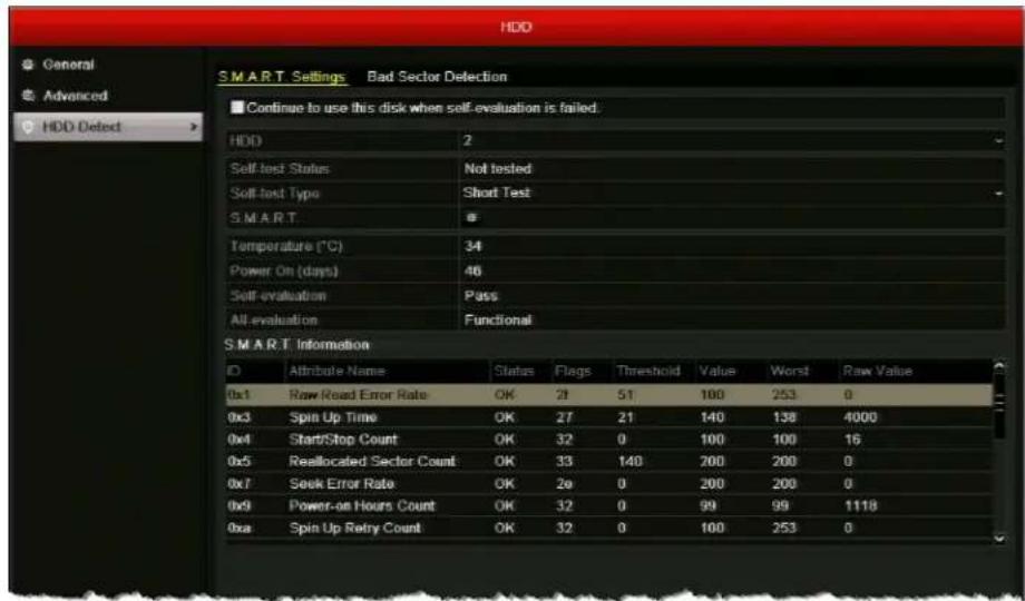
- Select the HDD you want to test from the HDD drop-down list.
- To continue using the HDD even it fails the self-test, select the Continue to use this disk when self-evaluation is failed check box.
- In the Self-test Type list, select one of the following options:

- Click the S.M.A.R.T. button to start the test. The test results are displayed under S.M.A.R.T. Information.
Detecting Bad Sectors
Bad hard disk drive sectors can cause the system to slow down when reading or writing data. This section describes how to detect and repair bad sectors.
To detect a bad sector:
- Go to Menu > HDD > HDD Detect > Bad Sector Detection.
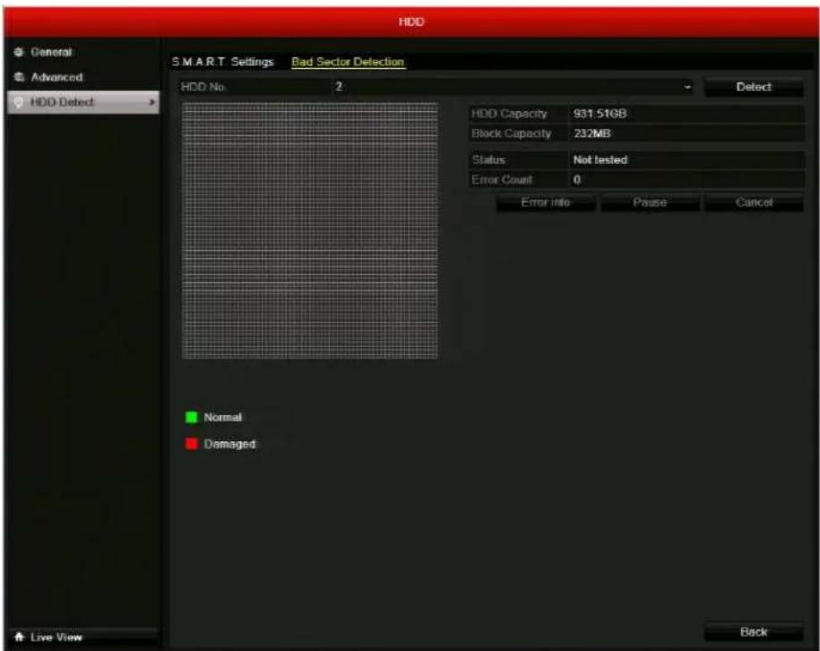
- Select the HDD you want to scan from the HDD No. drop-down list, and then click Detect. You can pause, resume, or cancel the detection process at any time.
- When the detection process has completed, click Error info to view any error information.
Configuring HDD Alarms
You can set up the DVR to generate alarm responses, such as an audible warning or notification email, when the hard disk drive is full or when an error is detected. See Configuring Exception Settings, page 96, for details.
11
Configuring Camera Settings
This chapter contains the following sections:
- Configuring OSD Settings, page 123
- Configuring Image Settings, page 125
- Configuring Privacy Masks, page 127
Configuring OSD Settings
You can customize the appearance and location of on-screen display (OSD) text, such as the date, time, and camera name.
To configure the OSD settings:
- Go to Menu > Camera > OSD.
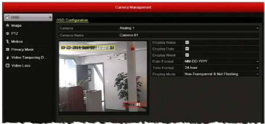
- Under OSD Configuration, configure the following settings:
| • Camera | Select the camera you want to configure OSD settings for by clicking a number from the drop-down list. |
| • Camera Name | If you want, you can enter a descriptive name for the camera (for example, "Front Door" instead of "Camera 01"). |
| • Display N | To display the camera name on screen, select the check box. To hide the camera name, clear the check box. |
| • Display D | To display the date on screen, select the check box. To hide the date, clear the check box. |
| • Display Week | To display the day of the week on screen, select the check box. To hide the day of the week, clear the check box. |
| • Date Format | Select format you want the date to be displayed in:YYYY-MM-DD, MM-DD-YYYY, or DD-MM-YYYY format. |
| • Time Form | Select the format you want the time to be displayed in:24-hour or 12-hour format. |
| • Display M | Select one of the following display modes:Transparent & Flashing, Transparent & Not Flashing, Non-Transparent & Flashing, or Non-Transparent & Not Flashing. |
- To adjust the location of the OSD text on the screen, using your mouse, drag the highlighted text boxes to the desired locations on the preview window. The date/time text box is highlighted yellow; the camera name text box is highlighted red.
- To copy these settings to one or more additional cameras, click Copy to open the Copy to window, select the camera(s) you want to copy the settings to, or click Analog to copy the settings to all cameras, and then click OK.
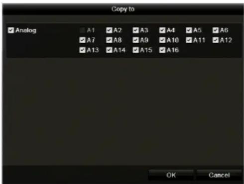
- Click Apply to save your settings.
To restore the default OSD settings:
• In Menu > Camera > OSD, click Restore.
Configuring Image Settings
You can create customized image settings for up to two time periods per camera to accommodate changing lighting conditions.
To configure camera image settings:
- Go to Menu > Camera > Image.
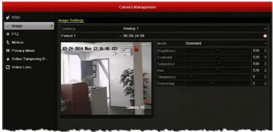
- Select the camera you want to configure image settings for.
- For Period 1, specify the time range that you want to configure the image settings for (such as 07:00–19:00).
-
Based on the anticipated lighting conditions for the specified time range, next to Mode, select one of the following:
-
Standard (default)
- l n d o o r
- Dim Light
-
Outdoor
-
Adjust the following image settings by moving the slider or by clicking the up/down arrows:
-
Brightness (0–255)
- Contrast (0–255)
- Saturation (0–255)
- Hue (0–255)
- Sharpness (0–15)
-
De-noising (0–5)
-
If you want to define different image settings for the remaining time (for example, from 19:01 to 06:59), select Period 2, and then repeat steps 7 and 8.
-
To copy these settings to one or more additional cameras, click Copy to open the Copy to window, select the camera(s) you want to copy the settings to, or click Analog to copy the settings to all cameras, and then click OK.
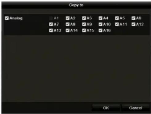
- Click Apply to save your settings.
To restore the default camera image settings:
• In Menu > Camera > Image, click Restore.
Configuring PTZ Connection Settings
See Configuring PTZ Connection Settings, page 46.
Configuring Motion Detection Settings
See Configuring Motion Detection Settings, page 89.
Configuring Privacy Masks
You can configure up to four privacy mask zones for each camera. Privacy mask zones conceal portions of the scene from the view of the operator.
To add a privacy mask zone:
- Go to Menu > Camera > Privacy Mask.
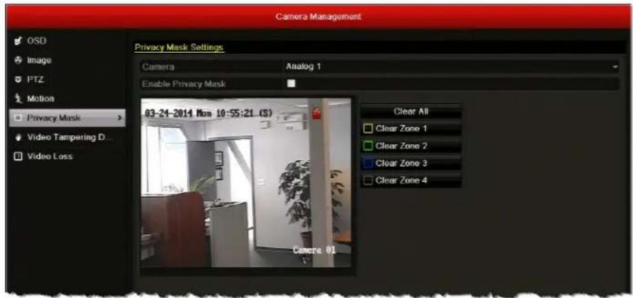
- Select the camera you want to create a privacy mask for by clicking a number in the Camera drop-down list.
- Select the Enable Privacy Mask check box.
- Drag the mouse over the area you want to mask on the preview window to draw a privacy mask zone. You can mask up to four areas.
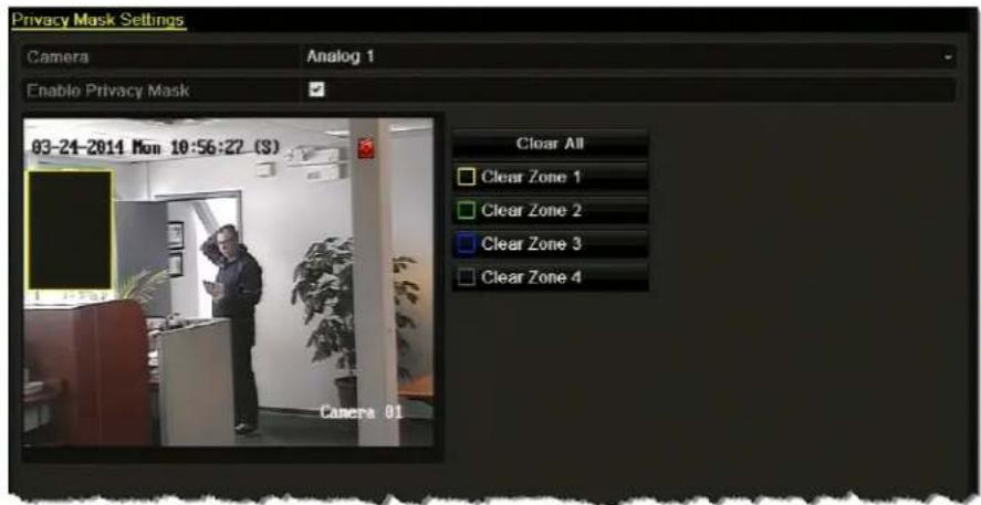
- To copy these settings to one or more additional cameras, click Copy to open the Copy to window, select the camera(s) you want to copy the settings to, or click Analog to copy the settings to all cameras, and then click OK.
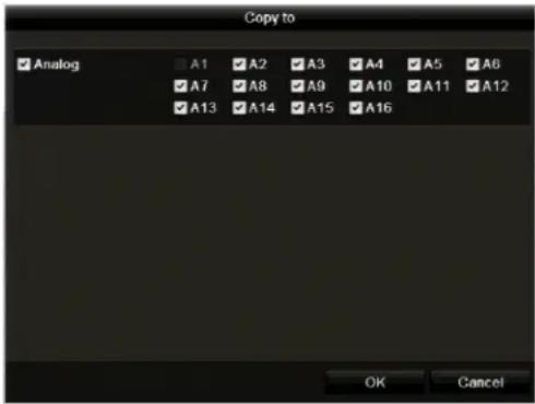
- Click Apply to save your settings.
To remove a privacy mask zone:
- In Menu > Camera > Privacy Mask, click the Clear Zone button corresponding to the zone(s) you want to remove, or click Clear All to clear all zones.
- Click Apply to save your settings.
Configuring Video Tampering Detection Settings
See Configuring Video Tampering Detection Settings, page 92.
Configuring Video Loss Settings
See Configuring Video Loss Detection Settings, page 94.
12
Managing the DVR
This chapter contains the following sections:
- Configuring General System Settings, page 132
• Viewing System Information, page 134
• Searching and Exporting Log Files, page 137 - Exporting and Importing Configuration Files, page 139
- Upgrading the Firmware, page 140
- Restoring the Default Settings, page 141
Configuring General System Settings
Follow the instructions below to configure general system settings, including video output standard, system date and time, daylight saving time (DST) settings, device name and number, video output brightness, main monitor output, and operation timeout parameters.
To configure general system settings:
- Go to Menu > Settings > General > General.
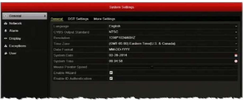
-
Configure the following settings:
-
Language Default language is English. Not user-configurable.
- CVBS Output Standard Sets the CVBS output standard. Select NTSC or PAL. Must be same as the video input standard.
- Resoluti Sets the VGA/HDMI output resolution. Select 1024×768/60HZ, 1280×720/60HZ, 1280×1024/60HZ, or 1920×1080/60HZ (1080P). Must be same as monitor screen resolution.
• Time Zone Sets the time zone. Select your time zone from the list. - Date Format Sets the date format. Select MM-DD-YYYY, YYYY-MM-DD, or DD-MM-YYYY.
- System Date Sets the system date. Click the calendar icon to display the on-screen calendar, and then select the current date.
- System Time Sets the system time. Click the clock icon, and then enter the current time (hh:mm:ss).
- Mouse Pointer Speed Sets the mouse pointer speed. Drag the slider to select the desired speed. 4 levels configurable.
- Enable Wi Enables/disables setup wizard. Select the check box to enable the wizard; clear the check box to disable it.
- Enable ID Authentication Enables/disables login password. Select the check box to enable the login password; clear the check box to disable it.
3. Click the DST Settings tab.
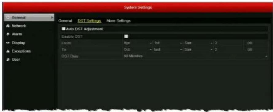
4. In DST Settings, do one of the following:
- To adjust for daylight saving time automatically, select the Auto DST Adjustment check box.
- To manually configure the settings, select the Enable DST check box, and then set the start and end dates and times for DST and the DST bias (recording overlap).
- To disable daylight saving time adjustment, leave both check boxes blank.
5. Click the More Settings tab.
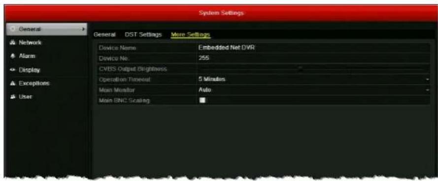
6. In More Settings, configure the following:
• Device Name Sets the device name. Enter a name for the device.
- Device Number
Sets the device's serial number. If you want, enter a number for the device between 1 and 255. The default number is 255.
• Output Br
Sets the video output brightness. Drag the slider to select the desired brightness. 10 levels configurable.
• Operation
SetsThe duration of menu inactivity before the system returns to live view mode. Select 1, 2, 5, 10, 20, 30 minutes or Never.
- Main Monitor
Sets the main output mode. Select Auto, HDMI/VGA, or Main BNC. The Auto setting detects the output automatically.
- Main BNC Scaling
Enables/disables scaling for main BNC output. Select the check box to enable scaling; clear the check box to disable it.
7. Click Apply to save your settings.
Viewing System Information
You can view system information pertaining to the device, cameras, record settings, alarm settings, network settings, and HDD.
To view device information:
- Go to Menu > Maintenance > System Info > Device Info. The device name, model, serial number, firmware version, encoding version, and MAC address are displayed.
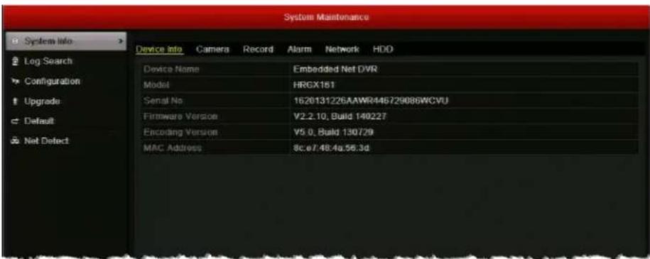
To view camera information:
- Go to Menu > Maintenance > System Info > Camera. Information for each camera, including its name, activity status, motion detection status, video tampering detection status, and video loss status, is displayed.
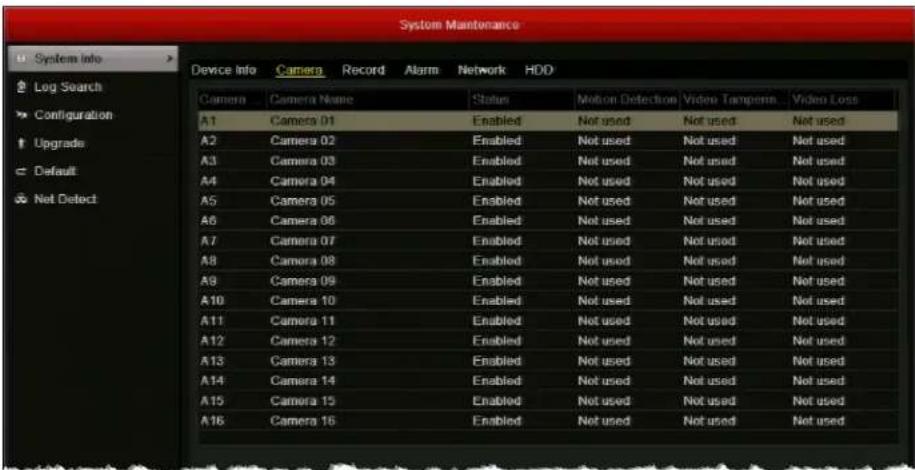
To view recording information:
- Go to Menu > Maintenance > System Info > Record. Recording details for each camera, including recording status, stream type, frame rate, bit rate, resolution, record type, encoding parameters, and redundant record status, are displayed.
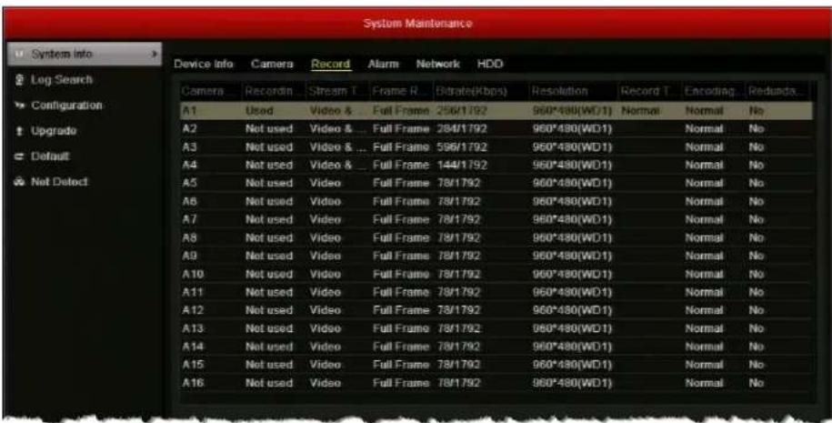
To view alarm input information:
- Go to Menu > Maintenance > System Info > Alarm. Details for the alarm inputs and alarm outputs, including alarm type (normally open or normally closed), alarm status, and triggered cameras, are displayed.
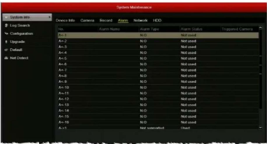
Note You can also view the alarm status by going to Menu > Settings > Alarm > Alarm Status.
To view the DVR's network settings:
- Go to Menu > Maintenance > System Info > Network. The DVR's network settings, including IP address, subnet mask, default gateway, DNS server addresses, DHCP, and PPOE settings, are displayed.
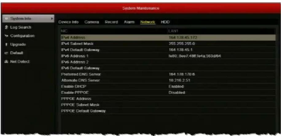
To view HDD information:
- Go to Menu > Maintenance > System Info > HDD. The hard disk drive details, including the label name, status, capacity, free space, read/write properties, type, and group, are displayed.
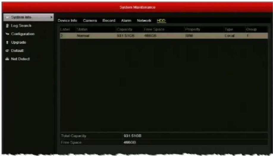
Searching and Exporting Log Files
Operation, alarm, exception, and HDD information is stored in log files. You can search and export these log files at any time.
To search log files:
- Go to Menu > Maintenance > Log Search > Log Search.
- Set the log search parameters, including Start Time, End Time, Major Type and Minor Type.
- Click Search to start searching log files. A list of log files matching the search parameters is displayed.
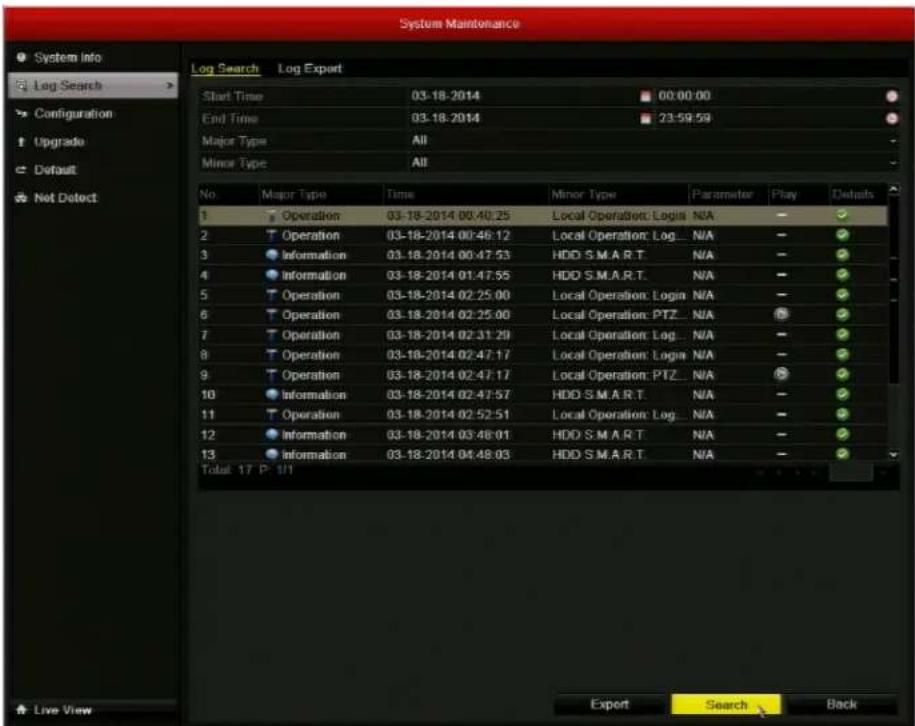
- To view a log file's details, double-click the log file or click the log file's √ button. The Log Information window opens.
To export specific log files:
- Go to Menu > Maintenance > Log Search > Log Search.
- Search for the log file(s) you want to export.
- Insert a USB flash drive or other external storage device into the USB port on the front of the DVR.
- Select the log file(s) that you want to export, and then click Export. The Export window opens.
- If you want, you can click New Folder to create a new folder on the storage device, or you can click Format to format the backup device.
- Click Export to save the log file(s) to the connect external storage device.
To export all log files stored on the HDD:
- Go to Menu > Maintenance > Log Search > Log Export.
- Insert a USB flash drive or other external storage device into the USB port on the front of the DVR.
- Select your HDD from the list, and then click Export. The Export window opens.
- If you want, you can click New Folder to create a new folder on the storage device, or you can click Format to format the backup device.
- Click Export to save all the log files on the HDD to the connected external storage device.
Note Exported log files are saved in .txt format. The file name follows the format YYYYMMDDhhmmss (for example, 20140319023628logBack.txt).
Exporting and Importing Configuration Files
Configuration files can be used to configure multiple HRGX DVRs with the same parameters. You can export configuration files to, or import configuration files from, an external storage device.
To export a configuration file:
- Insert a USB flash drive or other external storage device into the USB port on the front of the DVR.
- Go to Menu > Maintenance > Configuration.
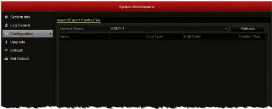
- Click Export to export configuration files to the connected external storage device. The message "Export succeeded" appears, and the file is added to the file list.
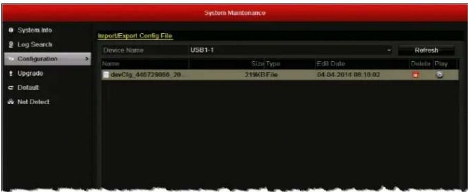
To import a configuration file:
- Insert a USB flash drive or other external storage device containing a configuration file into the USB port on the front of the DVR.
- Go to Menu > Maintenance > Configuration.
- Select the configuration file you want to import, and then click Import. The message "System will reboot automatically after importing. Continue?" appears. Click Yes.
Upgrading the Firmware
To obtain the latest firmware for your HRGX DVR, contact your Honeywell dealer. The firmware can be upgraded locally (by connecting a USB flash drive or other device containing the firmware file to the DVR) or remotely (via an FTP server).
To upgrade the firmware locally:
- Insert a USB flash drive containing the digicap.dav file into the USB port on the front of the DVR. Ensure that no other USB flash drive or storage device is connected to the DVR.
- Go to Menu > Maintenance > Upgrade > Local Upgrade. The digicap.dav file should appear in the file list.
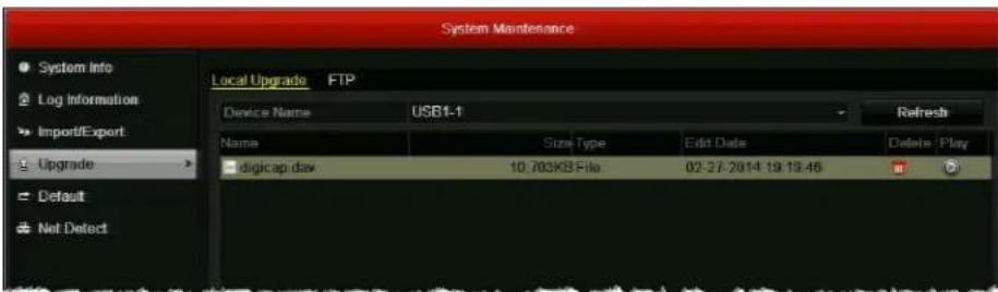
- Click digicap.dav, and then click Upgrade. The message "System will reboot automatically after upgrading completed. Continue?" appears. Click Yes.
To upgrade the firmware remotely via FTP:
- Ensure that your DVR and the PC running the FTP server are properly connected to the network and that the digicap.dav file is saved in the appropriate directory on the PC.
- Go to Menu > Maintenance > Upgrade > FTP.
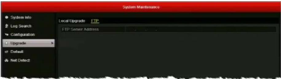
- In the FTP Server Address field, enter the address of the FTP server you want to access, and then click Upgrade.
- After the firmware upgrade is complete, restart the DVR.
To confirm that the firmware upgrade was successful:
- Go to Menu > Maintenance > System Info > Device Info.
- Next to Firmware Version, confirm that the firmware version shown on the screen matches the firmware version that you installed.
Restoring the Default Settings
You can restore your all of your DVR's settings, including user and network settings, to their factory defaults.
To restore the default settings:
- Go to Menu > Maintenance > Default.
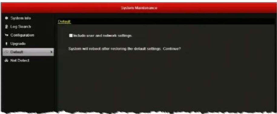
- If you want to restore user and network settings to their default settings, select the Include user and network settings check box. Otherwise, the current user and network settings will not be changed.
- Click OK to restore the default settings. The DVR restarts automatically after restoring the default settings.
13
Managing Users
This chapter contains the following sections:
- Types of User Accounts, page 143
- Adding Users, page 144
• Editing Users, page 145 - Deleting Users, page 147
• Changing the Admin Password, page 147
Types of User Accounts
The default user account of the DVR is an administrator account. The default user name is admin and the default password is 12345. The administrator ("admin") can add and delete additional user accounts and edit user account permissions.
There are three types of user accounts available:
Administrator The administrator account has unlimited access to the DVR user interface.
Operator An operator account has the following default permissions: local and remote camera operation (including PTZ camera operation), local and remote camera playback, remote two-way audio, local video export, and local and remote log searches. Additional permissions may be granted by the administrator.
Guest A guest account has the following default permissions: local and remote camera playback, and local and remote log searches. Additional permissions may be granted by the administrator.
Adding Users
You can add multiple operator or guest user accounts.
To add a user:
- Go to Menu > Settings > User.
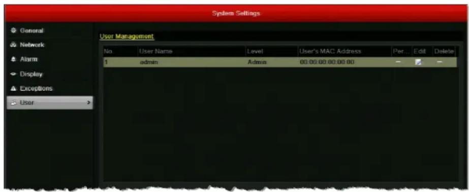
- Click Add to open the Add User window.
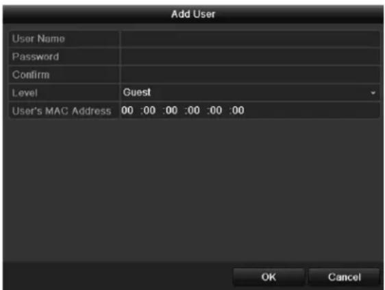
- Configure the following settings:
- User Name Enter the user name.
- Password Enter the password.
- Confirm Re-enter the password.
• Level Select Operator or Guest
- User's M A If the user is logging in to the DVR remotely, enter the MAC address of the user's PC. The user must log in from this MAC address to access the DVR.
- Click OK to save your settings and close the window. The user is added to the list of users.
Editing Users
You can edit permissions and account details of user accounts that you have created.
To edit a user's permissions:
- Go to Menu > Settings > User.
- Select from the list of users the user you want to edit permissions for.
- Click the Permission button √ to open the Permission window.
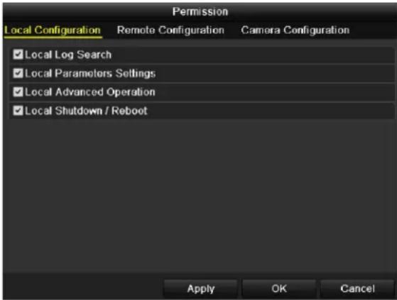
- Set the Local Configuration, Remote Configuration, and Camera Configuration permissions by selecting or clearing the appropriate check boxes.
Local Configuration
- Local Log Search: Locally search and view logs and system information.
- Local Parameters Settings: Configure parameters, restore factory defaults, and import/export configuration files.
- Local Advanced Operation: Manage HDD (initialize HDD, set HDD property), upgrade system firmware, clear I/O alarm output.
- Local Shutdown/Reboot: Shut down or reboot the DVR.
Remote Configuration
- Remote Log Search: Remotely view logs saved on the device.
- Remote Parameters Settings: Remotely configure parameters, restore factory defaults, and import/export configuration files.
- Remote Serial Port Control: Configure settings for RS-485 port.
- Remote Video Output Control: Send remote control panel signal.
- Two-Way Audio: Effect two-way radio communication between remote client and DVR.
- Remote Alarm Control: Remotely arm alarms and control alarm output.
- Remote Advanced Operation: Remotely manage HDD (initialize HDD, set HDD property), upgrade system firmware, clear I/O alarm output.
- Remote Shutdown/Reboot: Remotely shut down or reboot the DVR.
Camera Configuration
- Remote Live View: Remotely view live video from the selected camera(s).
- Local Manual Operation: Locally start/stop manual recording, capture still pictures, and manage alarm output of the selected camera(s).
- Remote Manual Operation: Remotely start/stop manual recording, capture still pictures, and manage alarm output of the selected camera(s).
- Local Playback: Locally play back recorded files of the selected camera(s).
- Remote Playback: Remotely play back recorded files of the selected camera(s).
- Local PTZ Control: Locally control PTZ movement of the selected camera(s).
- Remote PTZ Control: Remotely control PTZ movement of the selected camera(s).
- Local Video Export: Locally export recorded files of the selected camera(s).
Note Select the specific camera(s) for which each operation permission is configured, or select the Analog check box to select all cameras.
- Click Apply to save your settings, and then click OK to close the window.
To edit a user's account details:
- Go to Menu > Settings > User.
- Select from the list of users the user you want to edit account details for.
- Click the Edit button to open the Edit User window.
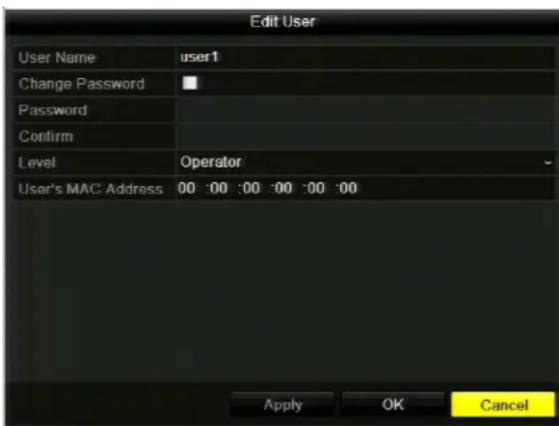
- Edit the one or more of the following settings:
| · User Name |
| · Password |
| · Confirm |
| · Level |
| · User's MAC Address |
- Click Apply to save your changes, and then click OK to close the window.
Deleting Users
You can delete a user account that you have created.
To delete a user:
- Go to Menu > Settings > User.
- Select from the list of users the user you want to delete.
- Click the Delete button 📄 to delete the user. The message "Delete this user?" appears. Click Yes.
Changing the Admin Password
If you are logged in as the admin user, you can change the admin password.
To change the admin password:
- Go to Menu > Settings > User.
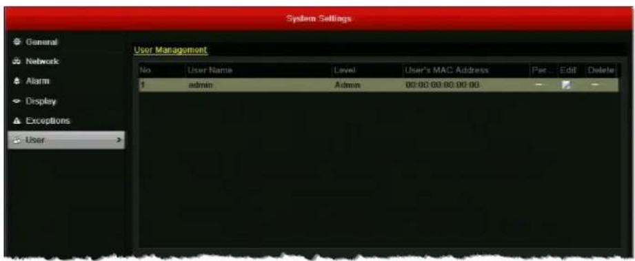
- Select admin, and then click the Edit button to open the Edit User window.
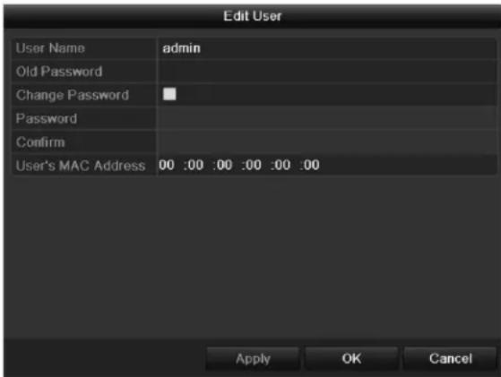
- In the Old Password field, enter the old admin password. (The default admin password is 12345.)
- Select the Change Password check box.
- In the Password field, enter the new admin password.
- In the Confirm field, re-enter the new admin password.
- Click Apply to save your settings, and then click OK to close the window.
Honeywell Security Products Americas (Head Office)
2700 Blankenbaker Pkwy, Suite 150
Louisville, KY 40299, USA
www.honeywell.com/security
+1 800 323 4576
Honeywell Security Europe/South Africa
Aston Fields Road, Whitehouse Industrial Estate
Runcorn, WA7 3DL, United Kingdom
www.honeywell.com/security/uk
+44 (0) 1928 754 028
Honeywell Security Products Americas
Caribbean/Latin America
9315 NW 112th Ave.
Miami, FL 33178, USA
www.honeywell.com/security/clar
+1 305 805 8188
Honeywell Security Asia Pacific
35F Tower A, City Center, 100 Zun Yi Road
Shanghai 200051, China
www.asia.security.honeywell.com
+86 21 2219 6888
Honeywell Security Middle East/N. Africa
Emaar Business Park, Sheikh Zayed Road
Building No. 2, Office No. 301
Post Office Box 232362
Dubai, United Arab Emirates
www.honeywell.com/security/me
+971 (0) 4 450 5800
Honeywell Security Northern Europe
Ampèrestraat 41
1446 TR Purmerend, The Netherlands
www.honeywell.com/security/nl
+31 (0) 299 410 200
72458 Albstadt, Germany
www.honeywell.com/security/de
+49 (0) 7431 801-0
Honeywell Security France
Immeuble Lavoisier
92160 Antony, France
www.honeywell.com/security/fr
+33 (0) 1 40 96 20 50
Honeywell Security Italia SpA
www.honeywell.com/security/it
+39 (0) 2 4888 051
Honeywell Security España
www.honeywell.com/security
+1 800 323 4576 (North America only)
https://www.honeywellsystems.com/ss/techsupp/index.html
Document 800-16694 – Rev A – 04/2014
© 2014 Honeywell International Inc. All rights reserved. No part of this publication may be reproduced by any means without written permission from Honeywell. The information in this publication is believed to be accurate in all respects. However, Honeywell cannot assume responsibility for any consequences resulting from the use thereof. The information contained herein is subject to change without notice. Revisions or new editions to this publication may be issued to incorporate such changes.