FD-224 - Router Phicomm - Free user manual and instructions
Find the device manual for free FD-224 Phicomm in PDF.

| Product Type | Router |
| Brand | Phicomm |
| Model | FD-224 |
| Wireless Standard | IEEE 802.11b/g/n |
| Frequency Band | 2.4 GHz |
| Maximum Data Rate | 300 Mbps |
| Ports | 1x WAN (10/100 Mbps), 4x LAN (10/100 Mbps) |
| Antennas | 2x Fixed external antennas |
| Security | WEP, WPA/WPA2, WPS |
| Power Supply | DC 9V 0.6A |
| Dimensions (W x D x H) | 150 x 110 x 30 mm |
| Weight | 200 g |
| LED Indicators | Power, WAN, LAN, Wireless |
| Operating Temperature | 0°C to 40°C |
| Humidity | 10% to 90% (non-condensing) |
| Certifications | CE, FCC, RoHS |
| Package Contents | Router, Power adapter, Ethernet cable, Manual |
| Warranty | 1 year |
Frequently Asked Questions - FD-224 Phicomm
User questions about FD-224 Phicomm
0 question about this device. Answer the ones you know or ask your own.
Ask a new question about this device
Download the instructions for your Router in PDF format for free! Find your manual FD-224 - Phicomm and take your electronic device back in hand. On this page are published all the documents necessary for the use of your device. FD-224 by Phicomm.
USER MANUAL FD-224 Phicomm
PHICOMM is the registered trademark of Shanghai Feixun Communication Co., Ltd. Other trademark or trade name mentioned herein are the trademark or registered trademark of the company. Copyright of the whole product as integration, including its accessories and software, belongs to Shanghai Feixun Communication Co., Ltd. Without the permission of Shanghai Feixun Communication Co., Ltd., individual or party is not allowed to copy, plagiarize, imitate or translate it into other languages.
All the photos and product specifications mentioned in this manual are for references only, as the upgrading of software and hardware, there will be changes. And if there are changes, PHICOMM is not responsible for informing in advance. If you want to know more information about our products, please visit our website at www.phicomm.com.
CONTENTS
Chapter 1: Introduction ...... 1
Product Overview....1
Main Features....1
Chapter 2: Hardware Installation .... 2
Front Panel 2
Rear Panel 3
Physical Connection....4
Chapter 3: Quick Installation .... 6
Configure Your PC....6
Install Your Modem Router....14
Chapter 4: Software Configuration.... 18
Quick Start 18
Interface Setup 18
Internet....19
LAN 25
Advanced Setup 26
Firewall 27
Routing 27
NAT....28
QoS....31
VLAN 33
ADSL 35
Access Management 35
ACL 36
Filter....37
SNMP 38
UPnP 38
DDNS 39
CWMP 40
Maintenance....40
Administration....41
Time Zone....41
Firmware 43
SysRestart 44
Diagnostics....45
Status....45
Device Info 46
System Log....47
Statistics 47
Help....48
Chapter 5: Specification.... 49
Appendix A: Troubleshooting 50
Appendix B: Certification 52
FCC Statement....52
CE Mark Warning 53
Appendix C: Glossary.... 54
Chapter 1: Introduction
Product Overview
Thank you for choosing PHICOMM FD-224 ADSL2/2+ Modem Router. This product is designed to provide a simple and cost-effective ADSL internet connection for a private Ethernet network. It is connected to network devices via standard Ethernet ports. The ADSL connection is made using ordinary telephone line with standard connectors. Multiple workstations can be networked to internet using a single Digital Subscriber Line (DSL) and single global IP address.
Quick Start of the Web based Setup Wizard is supplied and friendly help messages are provided for the configuration. Network and Router management is done through the Web based Setup Wizard which can be accessed through local Ethernet using any web browser.
ADSL FD-224 supports full-rate ADSL2/2+ connectivity conforming to the ITU and ANSI specifications. In addition to the basic DMT physical layer functions, the ADSL2/2+ PHY support dual latency ADSL2/2+ framing (fast and interleaved) and the I.432 ATM Physical Layer.
Main Features
• Provides 1 RJ11 DSL Port, 4 RJ45 LAN ports
• Up to 24Mbps downstream speed
- Reach of 6.5km from your ISP DSLAM
• Supports Build-in PPPoE
• DHCP Server/Relay/Client, UPnP, DDNS
• NAT, Static routing, and DMZ host
• QoS prioritization based on IP type of service
- Easy Setup Assistant provides quick & hassle free installation
• Supports web management
• Supports firmware upgrade
• Supports flow statistics
• Built-in firewall supporting IP/Mac address filtering
• Built-in DHCP server
Chapter 2: Hardware Installation
Front Panel

text_image
PHICOMM Power LAN1 LAN2 LAN3 LAN4 DSL InternetThe front panel of the ADSL2/2+ Modem Router includes one power indicator and three function indicators, as explained in table below:
| LED Status | Description | |
| Power | On Power is on | |
| Off Power is off | ||
| LAN(1-4) | On | There is a successful connection on the Ethernet port |
| Off | There is no connection on the Ethernet port or the connection is abnormal | |
| Blinking | Data is being transferred over the Ethernet port | |
| DSL | On | The Modem Router is synchronized |
| Blinking | The Modem Router is synchronizing | |
| Internet | Green | A successful PPP connection has been built |
| Off | The DSL port is linked down or the Modem Router works in Bridge mode | |
| Red | The PPP connection failed to be established |
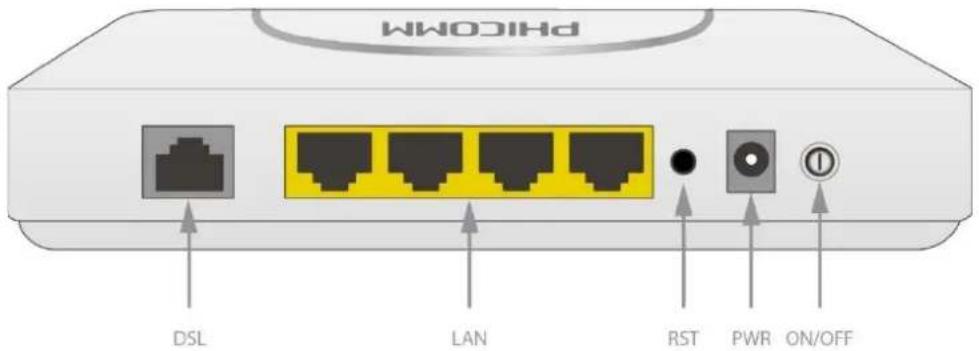
Rear Panel
text_image
WiCOM DSL LAN RST PWR ON/OFFThe rear panel of the ADSL2/2+ Modem Router includes 1 DSL port, 4 LAN ports, 1 ON/OFF button, 1 PWR connector, 1 RST button, as explained in table below:
| Interface/Button Function | |
| DSL | Connect to the Modem port of splitter or directly to the wall jack |
| LAN(1-4) | Connect to your network devices |
| ON/OFF | Turn on/off the power of ADSL2/2+ Modem Router |
| PWR Connect with a power adapter | |
| RST | Restore to factory default settings by pressing and holding for 5 seconds |
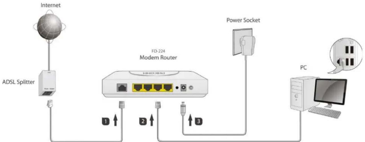
Physical Connection
flowchart
graph TD
    A["Internet"] --> B["ADSL Splitter"]
    B --> C["Modem Router"]
    C --> D["Power Socket"]
    D --> E["PC"]
    C --> F["1 ↑"]
    C --> G["2 ↑"]
    C --> H["3 ↑"]
    style A fill:#f9f,stroke:#333
    style B fill:#ccf,stroke:#333
    style C fill:#cfc,stroke:#333
    style D fill:#fcc,stroke:#333
    style E fill:#cff,stroke:#333
    style F fill:#ffc,stroke:#333
    style G fill:#ffc,stroke:#333
    style H fill:#ffc,stroke:#333
Before installing the device, please make sure your broadband service provided by your ISP is available. If there is any problem, please contact your ISP. You need to connect the device to the phone jack, the power outlet, and your computer or network. Before cable connection, turn off the power supply and keep your hands dry. You can follow the steps below to install it.
Step 1: Connect the ADSL Line.
Method one: Plug one end of the twisted-pair ADSL line into the DSL port on the rear panel of FD-224, and insert the other end into the wall socket.
Method two: You can use a separate splitter. External splitter can divide data and voice, and then you can access the Internet and make calls at the same time. The external splitter has three ports:
• LINE: Connect to the wall jack.
• PHONE: Connect to the phone sets.
- MODEM: Connect to the DSL port of FD-224. Plug one end of the twisted-pair ADSL line into the DSL port on the rear panel of FD-224. Connect the other end to the Modem port of the external splitter.
Step 2: Connect the Ethernet cable. Attach one end of a network cable to your computer's Ethernet port or a regular hub/switch port, and the other end to the LAN port on FD-224.
Step 3: Attach the power adapter. Connect the AC power adapter to the PWR connector on the rear of the device and plug in the adapter to a wall outlet or power extension.
Step 4: Turn on FD-224 and power on the computers and LAN devices.
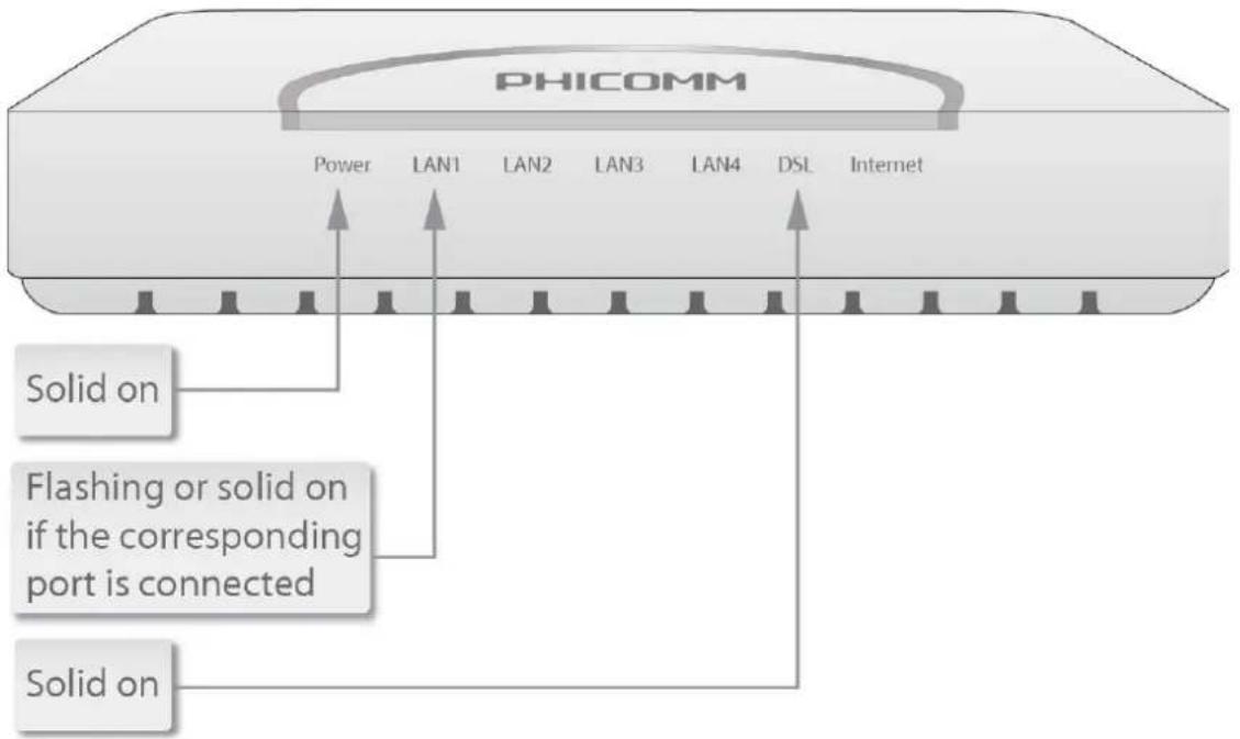
Note:
- If you currently use a modem, disconnect it, the Modem Router will replace your old modem.
• After the physical connection please check whether the LEDs of the Modem Router display normally as the diagram below describes.
text_image
PHICOMM Power LAN1 LAN2 LAN3 LAN4 DSL Internet Solid on Flashing or solid on if the corresponding port is connected Solid onChapter 3: Quick Installation
Configure Your PC
After you directly connect your PC to FD-224 or to a Hub/Switch which has connected to this Modem Router, we suggest you set your computer to obtain the IP address automatically. For Windows XP/2000
1) Click Start > Control Panel.

text_image
Admin Internet Internet Explorer E-mail Outlook Express V_KLay Notepad HyperTerminal Adobe Acrobat 8 Professional Shortcut to SecureCRT HyperSnap-DX 5 All Programs My Documents My Recent Documents My Pictures My Music My Computer My Network Places Control Panel Set Program Access and Defaults Printers and Faxes Help and Support Search Run... Log Off Turn Off Computer start2) Select and double click Network Connections.

text_image
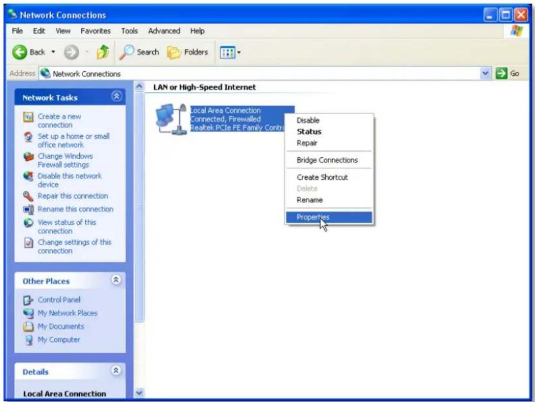
Control Panel File Edit View Favorites Tools Help Back Search Folders Address Control Panel Control Panel Switch to Category View See Also Windows Update Help and Support Accessibility Options Add Hardware Add or Remov... Administrative Tools Automatic Updates Date and Time Display Folder Options Fonts Game Controllers Internet Options Keyboard Mouse Network Connections Network Setup Wizard NVIDIA nView Desktop M... NVIDIA Phone and Modem ... Power Options Printers and Faxes Realtek HD Sound Eff... Regional and Language ... Scanners and Cameras Scheduled Tasks Security Center Sounds and Audio Devices Speech System Taskbar and Start Menu User Accounts Windows Firewall Wireless Network Set...3) Right click Local Area Connection and then select Properties.
text_image
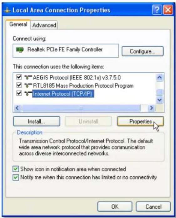
Network Connections File Edit View Favorites Tools Advanced Help Back Search Folders Address Network Connections LAN or High-Speed Internet Network Tasks Create a new connection Set up a home or small office network Change Windows Firewall settings Disable this network device Repair this connection Rename this connection View status of this connection Change settings of this connection Other Places Control Panel My Network Places My Documents My Computer Details Local Area Connection Local Area Connection Connected, Firewalled Realtek PCIe FE Family Control Disable Status Repair Bridge Connections Create Shortcut Delete Rename Properties4) Select Internet Protocol (TCP/IP) and click Properties.
text_image
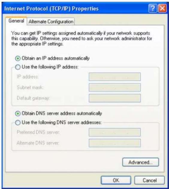
Local Area Connection Properties General Advanced Connect using: Realtek PCIe FE Family Controller Configure... This connection uses the following items: ✓ AEGIS Protocol (IEEE 802.1x) v3.7.5.0 ✓ RTL8185 Mass Production Protocol Program ✓ Internet Protocol (TCP/IP) Install... Uninstall Properties Description Transmission Control Protocol/Internet Protocol. The default wide area network protocol that provides communication across diverse interconnected networks. ✓ Show icon in notification area when connected ✓ Notify me when this connection has limited or no connectivity OK Cancel5) Select Obtain an IP address automatically and Obtain DNS server address automatically. Then click OK.
text_image
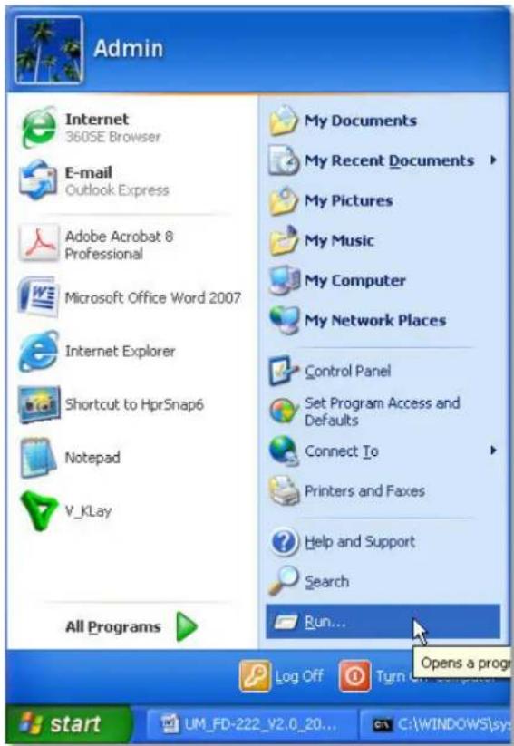
Internet Protocol (TCP/IP) Properties General Alternate Configuration You can get IP settings assigned automatically if your network supports this capability. Otherwise, you need to ask your network administrator for the appropriate IP settings. Obtain an IP address automatically Use the following IP address: IP address: ...... Subnet mask: ...... Default gateway: ...... Obtain DNS server address automatically Use the following DNS server addresses: Preferred DNS server: ...... Alternate DNS server: ...... Advanced... OK Cancel6) Run the Ping command in the command prompt to verify the network connection. Click Start menu on your desktop, select Run tab, type cmd in the field.
text_image
Admin Internet 360SE Browser E-mail Outlook Express Adobe Acrobat 8 Professional Microsoft Office Word 2007 Internet Explorer Shortcut to HprSnap6 Notepad V_Klay All Programs My Documents My Recent Documents My Pictures My Music My Computer My Network Places Control Panel Set Program Access and Defaults Connect To Printers and Faxes Help and Support Search Run... Open a progr Log Off Turn On Start UM_FD-222_Y2.0_20... C:\WINDOWS\sys
text_image
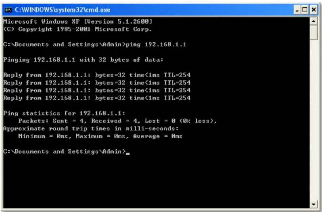
Run Type the name of a program, folder, document, or Internet resource, and Windows will open it for you. Open: cmd OK Cancel Browse...7) Then type ping 192.168.1.1, press Enter.
If the screen looks like the following, you have succeeded
text_image
C:\WINDOWS\system32\cmd.exe Microsoft Windows XP [Version 5.1.2600] (C) Copyright 1985-2001 Microsoft Corp. C:\Documents and Settings\Admin>ping 192.168.1.1 Pinging 192.168.1.1 with 32 bytes of data: Reply from 192.168.1.1: bytes=32 time<1ms TTL=254 Reply from 192.168.1.1: bytes=32 time<1ms TTL=254 Reply from 192.168.1.1: bytes=32 time<1ms TTL=254 Reply from 192.168.1.1: bytes=32 time<1ms TTL=254 Ping statistics for 192.168.1.1: Packets: Sent = 4, Received = 4, Lost = 0 (0% loss), Approximate round trip times in milli-seconds: Minimum = 0ms, Maximum = 0ms, Average = 0ms C:\Documents and Settings\Admin>For Windows Vista/7:
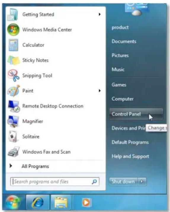
1) Click Start>Control Panel.
text_image
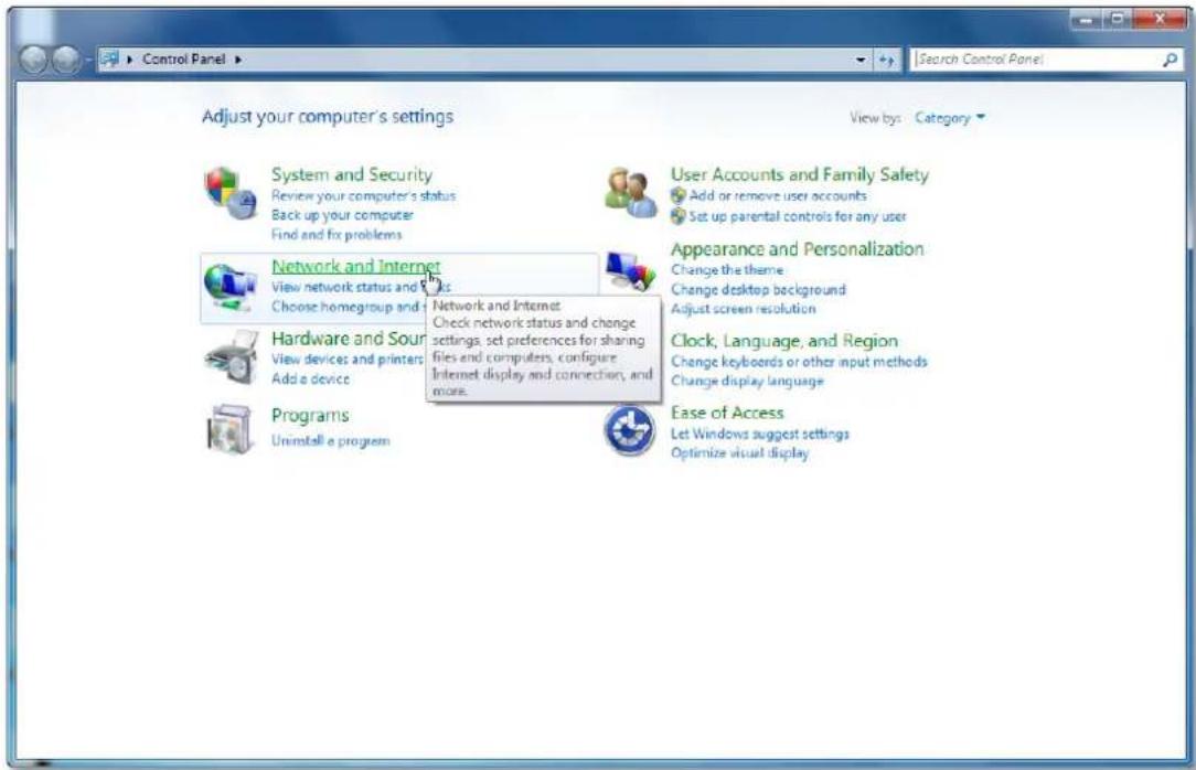
Getting Started Windows Media Center Calculator Sticky Notes Snipping Tool Paint Remote Desktop Connection Magnifier Solitaire Windows Fax and Scan All Programs Search programs and files product Documents Pictures Music Games Computer Control Panel Devices and Print Change Default Programs Help and Support Shut down2) Click Network and Internet.
text_image
Control Panel Adjust your computer's settings View by: Category System and Security Review your computer's status Back up your computer Find and fix problems Network and Internet View network status and links Choose homegroup and Hardware and Source View devices and printers Add a device Programs Uninstall a program User Accounts and Family Safety Add or remove user accounts Set up parental controls for any user Appearance and Personalization Change the theme Change desktop background Adjust screen resolution Clock, Language, and Region Change keyboards or other input methods Change display language Ease of Access Let Windows suggest settings Optimize visual display3) Click Network and Sharing Center.

text_image
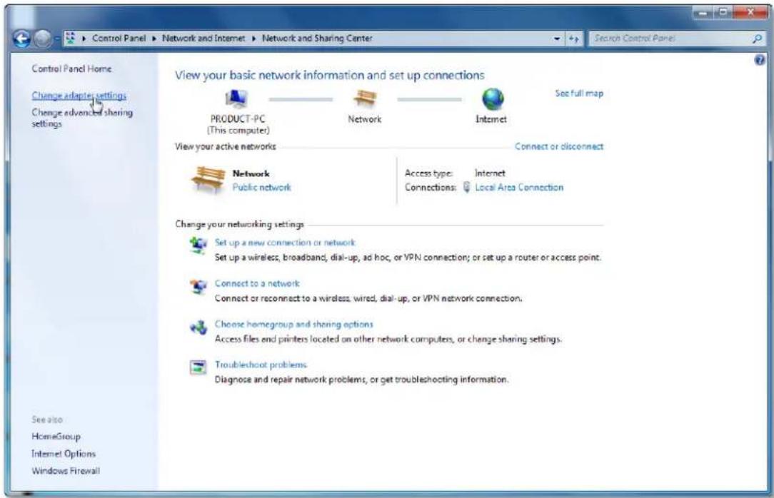
Control Panel Home System and Security Network and Internet Hardware and Sound Programs User Accounts and Family Safety Appearance and Personalization Clock, Language, and Region Ease of Access Network and Sharing Center View network status and text Connect to a network View network computers and devices Add a wireless device to the Network and Sharing Center Check network status, change network settings and set preferences for sharing files and printers. HomeGroup Choose homegroup and share Internet Options Change your homepage Manage browser add-ons Delete browsing history and cookies4) Go to Change Adapter Settings (win7)/Manage Network Connections (Vista).
text_image
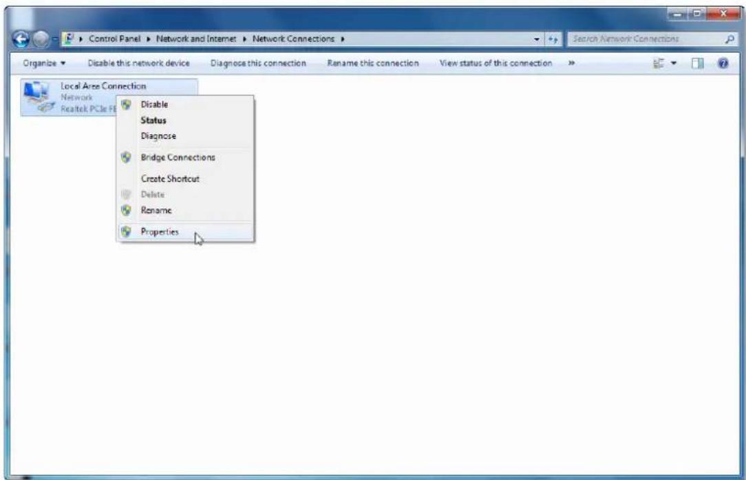
Control Panel Home Change adapters settings Change advanced sharing settings View your basic network information and set up connections PRODUCT-PC (This computer) Network Internet See full map View your active networks Connect or disconnect Network Public network Access type: Internet Connections: Local Area Connection Change your networking settings Set up a new connection or network Set up a wireless, broadband, dial-up, ad hoc, or VPN connection; or set up a router or access point. Connect to a network Connect or reconnect to a wireless, wired, dial-up, or VPN network connection. Choose homegroup and sharing options Access files and printers located on other network computers, or change sharing settings. Troubleshoot problems Diagnose and repair network problems, or get troubleshooting information. See also HomeGroup Internet Options Windows Firewall5) Right click Local Area Connection, choose Properties.
text_image
Control Panel > Network and Internet > Network Connections > Organize < Enable this network device Diagnose this connection Rename this connection View status of this connection > Local Area Connection Network Realtek PCIe FB Disable Status Diagnose Bridge Connections Create Shortcut Delete Rename Properties6) Select Internet Protocol Version 4 (TCP/IPv4) and click Properties.
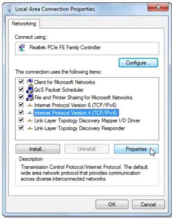
text_image
Local Area Connection Properties Networking Connect using: Realtek PCIe FE Family Controller Configure... This connection uses the following items: Client for Microsoft Networks QoS Packet Scheduler File and Printer Sharing for Microsoft Networks Internet Protocol Version 6 (TCP/IPv6) Internet Protocol Version 4 (TCP/IPv4) Link-Layer Topology Discovery Mapper I/O Driver Link-Layer Topology Discovery Responder Install... Uninstall Properties Description Transmission Control Protocol/Internet Protocol. The default wide area network protocol that provides communication across diverse interconnected networks. OK Cancel7) Select Obtain an IP address automatically and Obtain DNS server address automatically. Then click OK.

text_image
Internet Protocol Version 4 (TCP/IPv4) Properties General Alternate Configuration You can get IP settings assigned automatically if your network supports this capability. Otherwise, you need to ask your network administrator for the appropriate IP settings. Obtain an IP address automatically Use the following IP address: IP address: . Subnet mask: . Default gateway: . Obtain DNS server address automatically Use the following DNS server addresses: Preferred DNS server: . Alternate DNS server: . Validate settings upon exit Advanced... OK CancelNote: After your computer is configured successfully, go to the next section to configure the Modem Router via web. Otherwise, refer to the question 1 in Troubleshooting section to reset the modem.
Install Your Modem Router
To configure the device, you can either run the Resource CD or the Web based Setup Wizard. For first-time installation we recommend running the Resource CD, follow the step-by-step instructions to finish the installation. After the initial configuration is done, you can login to the Web based Setup Wizard to configure do some additional settings. Here we introduce how to set it up via Web based Setup Wizard.
Step 1: Open your web browser, in the address bar, type in 192.168.1.1

text_image
Address 192.168.1.1Step 2: You are prompt to enter the Username/Password (preset as admin/admin) which you can found on the label at the bottom of your router, and then click OK.

text_image
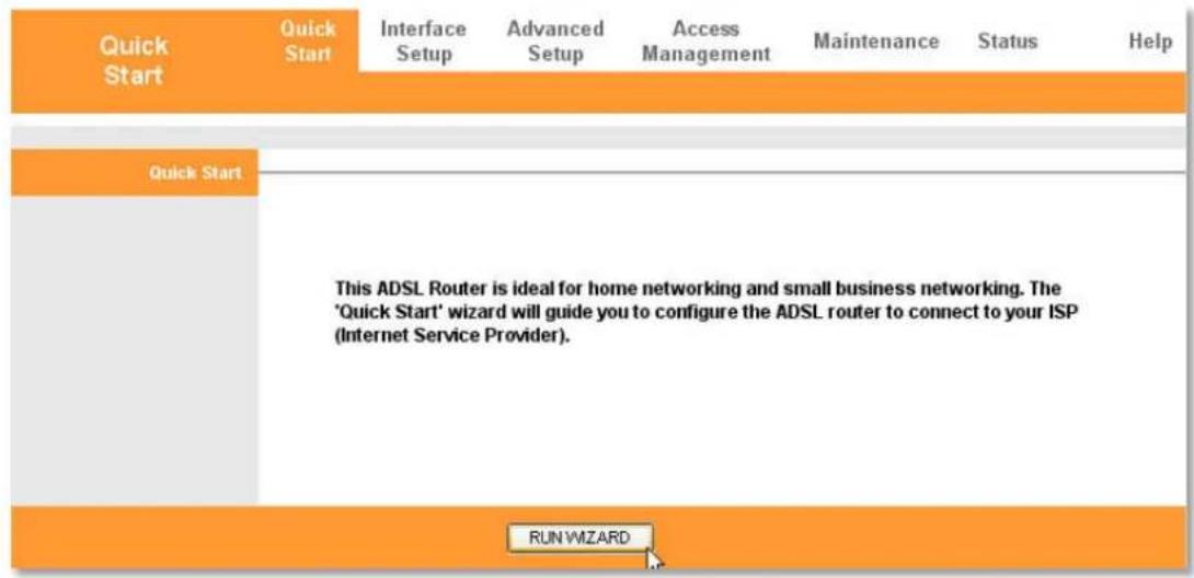
Connect to 192.168.1.1 ADSL Modem User name: admin Password: •••••• Remember my password OK CancelStep 3: Go to Quick Start tab, and then click RUN WIZARD.

text_image
Quick Start Quick Start Interface Setup Advanced Setup Access Management Maintenance Status Help This ADSL Router is ideal for home networking and small business networking. The 'Quick Start' wizard will guide you to configure the ADSL router to connect to your ISP (Internet Service Provider). RUN WIZARDStep 4: Click NEXT.
Quick Start
The Wizard will guide you through these four quick steps. Begin by clicking on NEXT.
Step 1. Set your new password
Step 2. Choose your time zone
Step 3. Set your Internet connection
Step 4. Save settings of this ADSL Router

Step 5: If you want to change the login password, put in the new password in this page. Otherwise just leave it blank, and then click NEXT.
Quick Start - Password
You may change the admin account password by entering in a new password. Click NEXT to continue.
New Password:
Confirmed Password :

Step 6: Choose your time zone, and then click NEXT.
Quick Start - Time Zone
Select the appropriate time zone for your location and click NEXT to continue.
(GMT) Greenwich Mean Time : Dublin, Edinburgh, Lisbon, London

BACK
NEXT
EXIT
Step 7: Choose the connection type provided by your ISP (take PPPoE/PPPoA as an example here), and then click NEXT.
Quick Start - ISP Connection Type
Select the Internet connection type to connect to your ISP. Click NEXT to continue.
Dynamic IP Address
Choose this option to obtain a IP address automatically from your ISP.
Static IP Address
Choose this option to set static IP information provided to you by your ISP.
PPPoE/PPPoA
Choose this option if your ISP uses PPPoE/PPPoA. (For most DSL users)
Bridge Mode
Choose this option if your ISP uses Bridge Mode.

Step 8: Put in Username, Password, VPI, VCI and Connection Type provided by your ISP. If you are not sure about the information, please confirm with your ISP. Then click NEXT.
Quick Start - PPPoE/PPPoA
Enter the PPPoE/PPPoA information provided to you by your ISP. Click NEXT to continue.
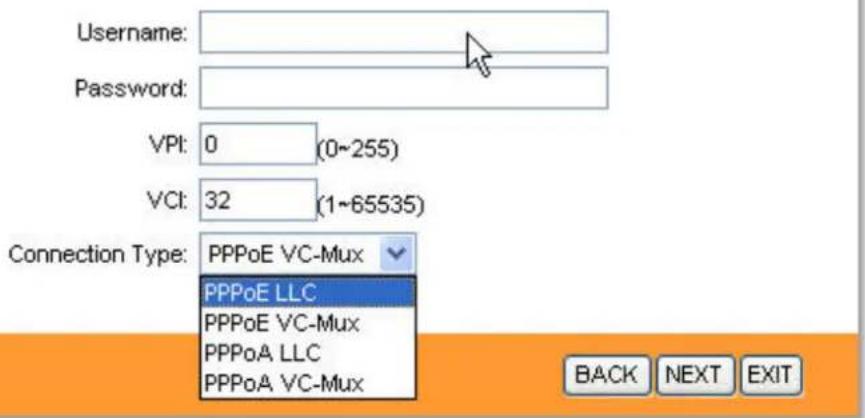
text_image
Username: Password: VPI: 0 (0~255) VCI: 32 (1~65535) Connection Type: PPPoE VC-Mux PPPoE LLC PPPoE VC-Mux PPPoA LLC PPPoA VC-Mux BACK NEXT EXITStep 9: Click NEXT.
Quick Start Complete !!
The Setup Wizard has completed. Click on BACK to modify changes or mistakes. Click NEXT to save the current settings.

Step 10: Click CLOSE.
Quick Start Completed !!
Saved Changes.

Note:
- Wait a moment, if the configuration is successful, the Internet LED light will finally turn green.
- The Internet light will not light on if the Modem Router works as bridge, please set up a broadband connection on your computer in that condition.
Chapter 4: Software Configuration
This User Manual recommends using the Quick Installation Guide for first-time installation. For advanced users, if you want to know more about this device and make use of its functions adequately, maybe you will get help from this chapter to configure the advanced settings through the Web based Setup Wizard. After your successful login, you can configure and manage the device. There are main menus on the top of the Web based Setup Wizard; submenus will be available after you click one of the main menus. In the center of the Web based Setup Wizard, there are the detailed configurations or status information. To apply any settings you have altered on the page, please click APPLY/SAVE button.
Quick Start
Please refer to Install Your Modem Router.
text_image
Quick Start Quick Start Interface Setup Advanced Setup Access Management Maintenance Status Help Quick Start This ADSL Router is ideal for home networking and small business networking. The 'Quick Start' wizard will guide you to configure the ADSL router to connect to your ISP (Internet Service Provider). RUN WIZARDInterface Setup
Choose Interface Setup, you can see two submenus: Internet, LAN.
Click any of them, you will be able to configure the corresponding function.

flowchart
graph LR
    A["Interface"] --> B["Quick Start"]
    B --> C["Internet"]
    C --> D["LAN"]
    D --> E["Advanced Setup"]
    E --> F["Access Management"]
    F --> G["Maintenance"]
    G --> H["Status"]
    H --> I["Help"]
Internet

text_image
Interface Quick Start Interface Setup Advanced Setup Access Management Maintenance Status Help Internet LAN ATM VC Virtual Circuit: PVC0 ▼ PVCs Summary Status: ● Activated ○ Deactivated VPI: 0 (range: 0~255) VCI: 32 (range: 1~65535) QoS ATM GoS: UBR PCR: 0 cells/second SCR: 0 cells/second MBS: 0 cells Encapsulation ISP: ○ Dynamic IP Address ○ Static IP Address ○ PPPoA/PPPoE ● Bridge Mode Bridge Mode Encapsulation: 1483 Bridged IP LLC SAVE DELETEATM VC: ATM settings are used to connect to your ISP. Your ISP provides VPI (Virtual Path Identifier), VCI (Virtual Channel Identifier) settings to you. In this Device, you can totally setup 8 VCs on different encapsulations, if you apply 8 different virtual circuits from your ISP. You need to activate the VC to take effect. For PVCs management, you can use ATM QoS to setup each PVC traffic priority.
Virtual Circuit: Select the VC number you want to setup, PVC0\~PVC7.
Status: If you want to use a designed VC, you should activate it.
VPI: Identify the virtual path between endpoints in an ATM network. The valid range is from 0 to 255. Please input the value provided by your ISP.
VCI: Identify the virtual channel endpoints in an ATM network. The valid range is from 32 to 65535 (1 to 31 is reserved for well-known protocols). Please input the value provided by your ISP.
PVCs Summary: You can view the summary information about the PVCs.
QoS: Select the Quality of Service types for this Virtual Circuit, including CBR (Constant Bit Rate), UBR (Unspecified Bit Rate) and VBR (Variable Bit Rate). These QoS types are all controlled by the parameters specified below, including PCR (Peak Cell Rate), SCR (Sustained Cell Rate) and MBS (Maximum Burst Size), please configure them according your needs.
Encapsulation: There are four connection types: Dynamic IP Address, Static Address, PPPoA/PPPoE and Bridge Mode. Please choose the designed type that you want to use. After that, you should follow the configuration below to proceed.
1. Dynamic IP Address
Select this option if your ISP provides you an IP address automatically. This option is typically used for Cable services. Please enter the Dynamic IP information accordingly.
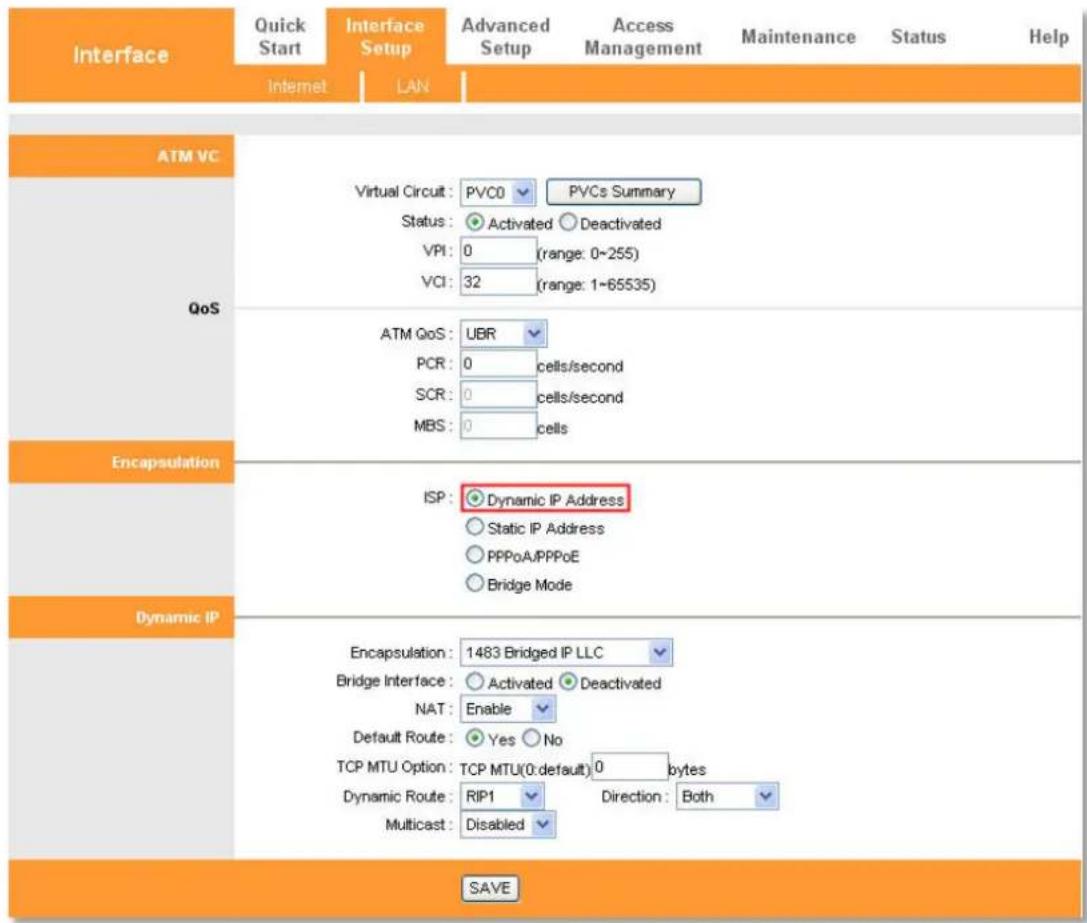
text_image
Interface Quick Start Internet LAN Advanced Setup Access Management Maintenance Status Help ATM VC Virtual Circuit: PVC0 ▼ PVCs Summary Status: ● Activated ○ Deactivated VPI: 0 (range: 0~255) VCI: 32 (range: 1~65535) QoS ATM QoS: UBR PCR: 0 cells/second SCR: 0 cells/second MBS: 0 cells Encapsulation ISP: ● Dynamic IP Address ○ Static IP Address ○ PPPoA/PPPoE ○ Bridge Mode Dynamic IP Encapsulation: 1483 Bridged IP LLC Bridge Interface: ○ Activated ● Deactivated NAT: Enable Default Route: ● Yes ○ No TCP MTU Option: TCP MTU(0:default) 0 bytes Dynamic Route: RIP1 Direction: Both Multicast: Disabled SAVEEncapsulation: Select the encapsulation mode for the Dynamic IP Address, you can leave it default.
Bridge Interface: Activate the option, and the Router can also work in Bridge mode.
NAT: Select this option to Enable/Disable the NAT (Network Address Translation) function for this VC. The NAT function can be activated or deactivated per PVC basis.
Default Route: If enable this function, the current PVC will be considered as the default gateway to internet from this device.
TCP MTU Option: Enter the TCP MTU as you desire.
Dynamic Route: Select this option to specify the RIP (Routing Information protocol) version for WAN interface, including RIP1, RIP2-B and RIP2-M. RIP2-B and RIP2-M are both sent in RIP2 format, the difference is that RIP2-M using Multicast, while RIP2-B using Broadcast format.
Direction: Select this option to specify the RIP direction. None is for disabling the RIP function. Both means the ADSL Router will periodically send routing information and accept routing information, and then incorporate them into routing table. IN only means the ADLS router will
only accept but will not send RIP packet. OUT only means the ADLS router will only send but will not accept RIP packet.
Multicast: Select IGMP version, or disable the function. IGMP (Internet Group Multicast Protocol) is a session-layer protocol used to establish membership in a multicast group. The ADSL ATU-R supports both IGMP v1 and IGMP v2. Select Disabled to disable this function.
2. Static IP Address
Select this option if your ISP provides static IP information to you. You should set static IP address, IP subnet mask, and gateway address on the screen below.
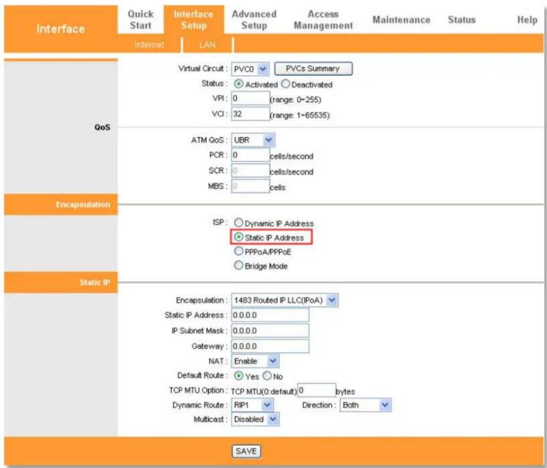
text_image
Interface Quick Start Internet LAN Advanced Setup Access Management Maintenance Status Help Virtual Circuit: PVC0 ▼ PVCs Summary Status: ● Activated ○ Deactivated VPI: 0 (range: 0-255) VCI: 32 (range: 1-65535) QoS ATM QoS: UBR PCR: 0 cells/second SCR: 0 cells/second MBS: 0 cells Encapsulation ISP: ○ Dynamic IP Address ○ Static IP Address ○ PPPoA/PPPoE ○ Bridge Mode Static IP Encapsulation: 1483 Routed IP LLC(IPoA) ▼ Static IP Address: 0.0.0.0 IP Subnet Mask: 0.0.0.0 Gateway: 0.0.0.0 NAT: Enable ▼ Default Route: ● Yes ○ No TCP MTU Option: TCP MTU(0:default) 0 bytes Dynamic Route: RIP1 Direction: Both ▼ Multicast: Disabled ▼ SAVENote: Each IP address entered in the fields must be in the appropriate IP form, which is four IP octets separated by a dot (x.x.x.x), such as 192.168.1.100. The Router will not accept the IP address if it is not in this format.
3. PPPoA/PPPoE
Select this option if you have a username and password to access internet. This option is typically used for DSL services. Select Dynamic to obtain an IP address automatically for your PPP connection. Select Static to use a static IP address for your PPP connection. Please enter the information accordingly.

text_image
Encapsulation ISP: ○ Dynamic IP Address ○ Static IP Address ● PPPoA/PPPoE ○ Bridge Mode PPPoE/PPPoA Service name: Username: Password: Encapsulation: PPPoE LLC Bridge Interface: ○ Activated ● Deactivated Connection: ● Always On (Recommended) ○ Connect On-Demand (Close if idle for 0 minutes) ○ Connect Manually TCP MSS Option: TCP MSS(0:default) 0 bytes IP Address Get IP Address: ○ Static ● Dynamic Static IP Address: 0.0.0.0 IP Subnet Mask: 0.0.0.0 Gateway: 0.0.0.0 NAT: Enable Default Route: ● Yes ○ No TCP MTU Option: TCP MTU(0:default) 0 bytes Dynamic Route: RIP1 ▼ Direction: Both ▼ Multicast: Disabled ▼ MAC Spoofing: ○ Enabled ● Disabled 00.00.00.00.00.00Service name: This is optional, if you don't have a service name, leave it blank.
Username: Enter your username for your PPPoA/PPPoE connection.
Password: Enter your password for your PPPoA/PPPoE connection.
Encapsulation: For both PPPoA/PPPoE connection, you need to specify the type of Multiplexing, either LLC or VC -Mux.
Bridge Interface: Activate the option, the Router can also work in Bridge mode.
Connection: For PPPoA/PPPoE connection, you can select Always on, Connect on-Demand or Connect Manually. Connect on demand is dependent on the traffic. If there is no traffic (or Idle) for a pre-specified period of time, the connection will tear down automatically. And once there is traffic sending or receiving, the connection will be automatically on.
TCP MSS Option: Enter the TCP MSS as you desire.
Get IP Address: For PPPoA/PPPoE connection, you need to specify the public IP address for this Modem Router. The IP address can be either dynamically (via DHCP) or given IP address
provided by your ISP. For Static IP, you need to specify the IP address, Subnet Mask and Gateway address.
NAT: Select this option to Enable/Disable the NAT (Network Address Translation) function for this VC. The NAT function can be activated or deactivated per PVC basis.
Default Route: Select Yes to configure the PVC as the default gateway to internet from this device.
TCP MTU Option: Enter the TCP MTU as you desire.
Dynamic Route: Select this option to specify the RIP (Routing Information protocol) version for WAN interface, including RIP1, RIP2-B and RIP2-M. RIP2-B and RIP2-M are both sent in RIP2 format, the difference is that RIP2-M using Multicast, while RIP2-B using Broadcast format.
Direction: Select this option to specify the RIP direction. None is for disabling the RIP function. Both means the ADSL Router will periodically send routing information and accept routing information, and then incorporate them into routing table. IN only means the ADLS router will only accept but will not send RIP packet. OUT only means the ADSL router will only send but will not accept RIP packet.
Multicast: Select IGMP version, or disable the function. IGMP (Internet Group Multicast Protocol) is a session-layer protocol used to establish membership in a multicast group. The ADSL ATU-R supports both IGMP v1 and IGMP v2. Select Disabled to disable this function.
MAC Spoofing: Enable the MAC Spoofing, and enter a MAC address to configure the WAN port. It makes your inside network appear as a device with this MAC address to the outside world.
4. Bridge Mode
If you select this type of connection, the modem can be configured to act as a bridging device between your LAN and your ISP. Bridges are devices that enable two or more networks to communicate as if they are two segments of the same physical LAN.

text_image
Interface Quick Start Internet LAN Advanced Setup Access Management Maintenance Status Help ATM VC Virtual Circuit: PVC0 ▼ PVCs Summary Status: ● Activated ○ Deactivated VPI: 0 (range: 0~255) VCI: 32 (range: 1~65535) QoS ATM QoS: UBR PCR: 0 cells/second SCR: 0 cells/second MBS: 0 cells Encapsulation ISP: ○ Dynamic IP Address ○ Static IP Address ○ PPPoA/PPPoE ● Bridge Mode Bridge Mode Encapsulation: 1483 Bridged IP LLC SAVE DELETENote: After you finish the Internet configuration, please click SAVE to make the settings take effect.
LAN

text_image
Interface Quick Start Interface Setup Advanced Setup Access Management Maintenance Status Help Internet LAN Router Local IP IP Address: 192.168.1.1 IP Subnet Mask: 255.255.255.0 Dynamic Route: RIP2-B Direction: None Multicast: Disabled IGMP Snoop: Disabled Enabled DHCP DHCP: Disabled Enabled Relay DHCP Server Starting IP Address: 192.168.1.2 Current Pool Summary IP Pool Count: 32 Lease Time: 259200 seconds (0 sets to default value of 259200) DNS DNS Relay: Use Auto Discovered DNS Server Only Primary DNS Server: N/A Secondary DNS Server: N/A SAVE CANCELRouter Local IP: These are the IP settings of the LAN interface for the device. These settings may be referred to as private settings. You may change the LAN IP address if necessary. The LAN IP address is private to your internal network and cannot be seen on the Internet.
IP Address: Modem Router's local IP Address, you can access to the Web based Setup Wizard via the IP Address, the default value is 192.168.1.1.
IP Subnet Mask: Enter the Subnet Mask, the default value is 255.255.255.0.
Dynamic Route: Select this option to specify the RIP (Routing Information protocol) version for LAN interface, including RIP1, RIP2-B and RIP2-M. RIP2-B and RIP2-M are both sent in RIP2 format, the difference is that RIP2-M using Multicast, while RIP2-B using Broadcast format.
Multicast: Select IGMP version, or disable the function. IGMP (Internet Group Multicast Protocol) is a session-layer protocol used to establish membership in a multicast group. The ADSL ATU-R supports both IGMP v1 and IGMP v2. Select Disabled to disable this function.
IGMP Snoop: Activate the IGMP Snoop function if you need.
DHCP: Select Enabled, then you will see the screen below.
The Modem Router will work as a DHCP server, it becomes the default gateway for DHCP clients connected to it. DHCP stands for Dynamic Host Control Protocol. The DHCP Server gives out IP addresses when a device is booting up and request an IP address to be logged on to the network. That device must be set as a DHCP client to obtain the IP address automatically.
By default, the DHCP Server is enabled. The DHCP address pool contains the range of the IP address that will automatically be assigned to the network clients.
Starting IP Address: Enter the starting IP address for the DHCP server's IP assignment. Because the default IP address for the Router is 192.168.1.1, the default Start IP Address is 192.168.1.2, and the Start IP Address must be 192.168.1.2 or greater, but smaller than 192.168.1.254.
IP Pool Count: The max user pool size.
Lease Time: The length of time for the IP lease. After the dynamic IP address has expired, the user will be automatically assigned a new dynamic IP address. The default is 259200 seconds.
DNS Relay: If you want to disable this feature, you just need to set both Primary and secondary DNS IP to 0.0.0.0. If you want to use DNS relay, you can setup DNS server IP to 192.168.1.1 on their computer.
If not, the device will perform as no DNS relay.
Primary DNS Server: Type in your preferred DNS server.
Secondary DNS Server: Type in your secondary DNS server.
Current Pool Summary: Click this button, you can view the IP addresses that the DHCP Server gives out.
Note: If Automatically is selected in DNS Relay, this router will accept the first received DNS assignment from one of the PPPoA, PPPoE or MER/DHCP enabled PVC(s) during the connection establishment. If Manually is selected in DNS Relay, it is necessary for you to enter the primary and optional secondary DNS server IP addresses. After typing in the address, click SAVE button to save it and invoke it.
DHCP Relay: Select Relay, the Router will work as a DHCP Relay. A DHCP relay is a computer that forwards DHCP data between computers that request IP addresses and the DHCP server that assigns the addresses. Each of the device's interfaces can be configured as a DHCP relay. If it is enabled, the DHCP requests from local PCs will forward to the DHCP server runs on WAN side. To have this function working properly, please run on router mode only, disable the DHCP server on the LAN port, and make sure the routing table has the correct routing entry.

text_image
DHCP DHCP Relay DHCP : ○ Disabled ○ Enabled ● Relay DHCP Server IP for Relay : 0.0.0.0 Agent SAVE CANCELDHCP Server IP for Relay Agent: Enter the DHCP server IP Address runs on WAN side.
Note: If you select Disabled, the DHCP function will not take effect. DHCP Relay may be no use if default route is not dynamic or static routing mode.
Advanced Setup
Choose Advanced Setup, you can see the submenus.
Click any of them, and you will be able to configure the corresponding function.

flowchart
graph LR
    A["Advanced"] --> B["Quick Start"]
    B --> C["Interface Setup"]
    C --> D["NAT"]
    D --> E["QoS"]
    E --> F["VLAN"]
    F --> G["ADSL"]
    G --> H["Status"]
    H --> I["Help"]
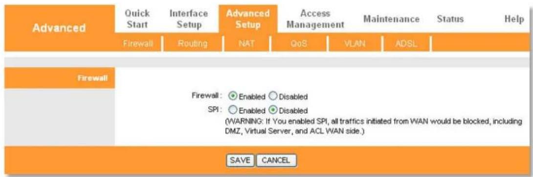
Firewall
text_image
Advanced Quick Start Interface Setup Advanced Setup Access Management Maintenance Status Help Firewall Routing NAT QoS VLAN ADSL Firewall Firewall: ○ Enabled ○ Disabled SPI: ○ Enabled ○ Disabled (WARNING: If You enabled SPI, all traffics initiated from WAN would be blocked, including DMZ, Virtual Server, and ACL WAN side.) SAVE CANCELFirewall: Select this option can automatically detect and block Denial of Service (DoS) attacks, such as Ping of Death, SYN Flood, Port Scan and Land Attack.
SPI: If you enable SPI, all traffics initiated from WAN would be blocked, including DMZ, Virtual Server, and ACL WAN side.
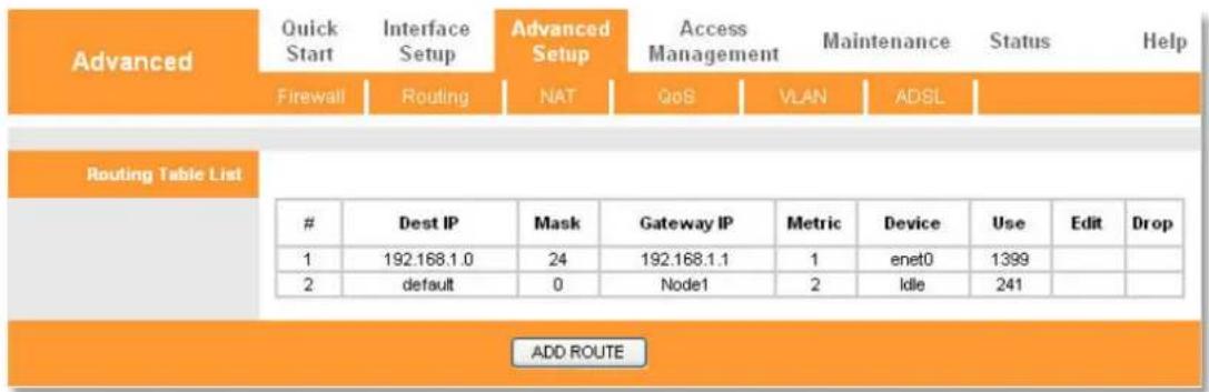
Routing
text_image
Advanced Quick Start Interface Setup Advanced Setup Access Management Maintenance Status Help Firewall Routing NAT QoS VLAN ADSL Routing Table List # Dest IP Mask Gateway IP Metric Device Use Edit Drop 1 192.168.1.0 24 192.168.1.1 1 enet0 1399 2 default 0 Node1 2 Idle 241 ADD ROUTEClick ADD ROUTE button to add a new route on the next screen.
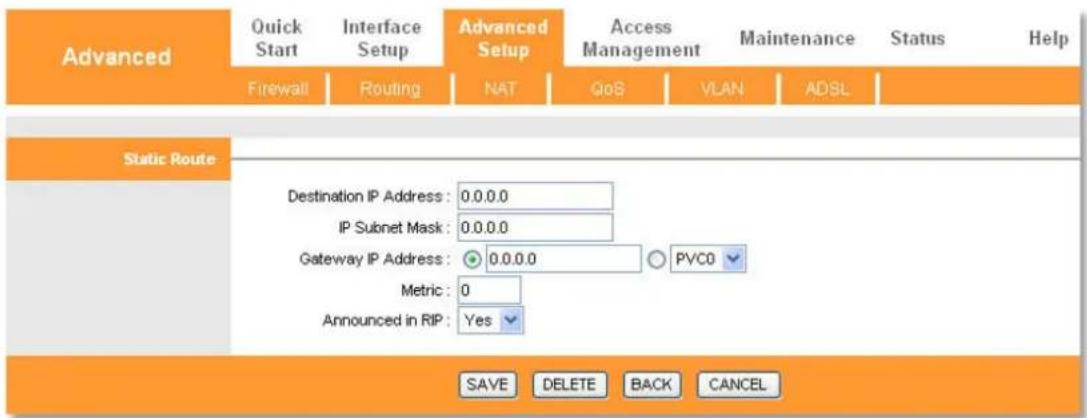
text_image
Advanced Quick Start Interface Setup Advanced Setup Access Management Maintenance Status Help Firewall Routing NAT QoS VLAN ADSL Static Route Destination IP Address: 0.0.0.0 IP Subnet Mask: 0.0.0.0 Gateway IP Address: 0.0.0.0 Metric: 0 Announced in RIP: Yes PVC0 SAVE DELETE BACK CANCELDestination IP Address: This parameter specifies the IP network address of the final destination.
IP Subnet Mask: Enter the subnet mask for this destination.
Gateway IP Address: Enter the IP address of the gateway. The gateway is an immediate neighbor of your Modem Router that will forward the packet to the destination. On the LAN, the gateway must be a router on the same segment as your Router; over Internet, the gateway must be the IP address of one of the remote nodes.
Metric: Metric represents the cost of transmission for routing purposes. IP Routing uses hop count as the measurement of cost, with a minimum of 1 for directly connected networks. Enter a number that approximates the cost for this link. The number need not to be precise, but it must between 1 and 15. In practice, 2 or 3 is usually a good number.
Announced in RIP: It indicates whether this route rule is included in RIP broadcasts. If select Yes, the route to this remote node will be propagated to other hosts through RIP broadcasts.
Otherwise, this route is kept private and is not included in RIP broadcasts.
NAT
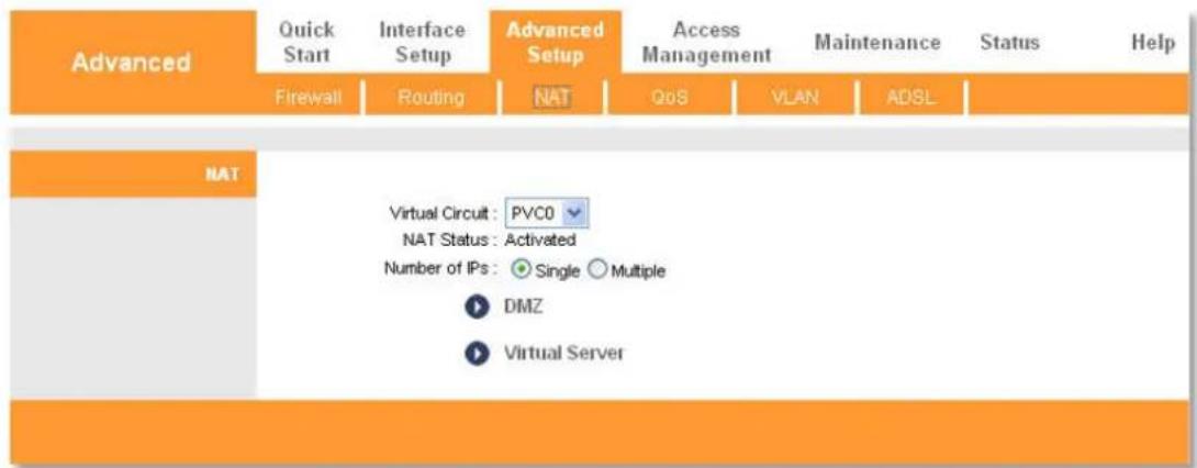
text_image
Advanced Quick Start Interface Setup Advanced Setup Access Management Maintenance Status Help Firewall Routing NAT QoS VLAN ADSL NAT Virtual Circuit: PVC0 NAT Status: Activated Number of IPs: Single Multiple DMZ Virtual ServerVirtual Circuit: Enter Virtual Circuit Index that you plan to setup for the NAT function.
NAT Status: This field shows the current status of the NAT function for the current VC.
Number of IPs: This field is to specify how many IPs are provided by your ISP for current VC. It can be single IP or multiple IPs. Only if we choose Multiple the menu of IP Address Mapping (for Multiple IP Service) can appear. We select Multiple to explain.
Note: For VCs with single IP, they share the same DMZ and Virtual Servers; for VCs with multiple IPs, each VC can set DMZ and Virtual Servers. Furthermore, for VCs with multiple IPs, they can define the Address Mapping rules; for VCs with single IP, since they have only one IP, there is no need to individually define the Address Mapping rule.
DMZ
A DMZ (demilitarized zone) is a host between a private local network and the outside public network. It allows outside users to access to a server that has company data directly. Users of the public network outside the company can access to the DMZ host. Please assign a static IP address to the destination computer before you use this feature.

text_image
Advanced Quick Start Interface Setup Advanced Setup Access Management Maintenance Status Help Firewall Routing NAT QoS VLAN ADSL DMZ DMZ setting for : Single IP Account DMZ : ○ Enabled ● Disabled DMZ Host IP Address: 0.0.0.0 SAVE BACKDMZ Host IP Address: Enter the specified IP Address for DMZ host on the LAN side.
Virtual Server
Virtual Server is the server or server(s) behind NAT (on the LAN), for example, Web server or FTP server, which you can make visible to the outside world even though NAT makes your whole inside network appear as a single machine to the outside world. Please assign a static IP address to the destination computer before you use this feature.
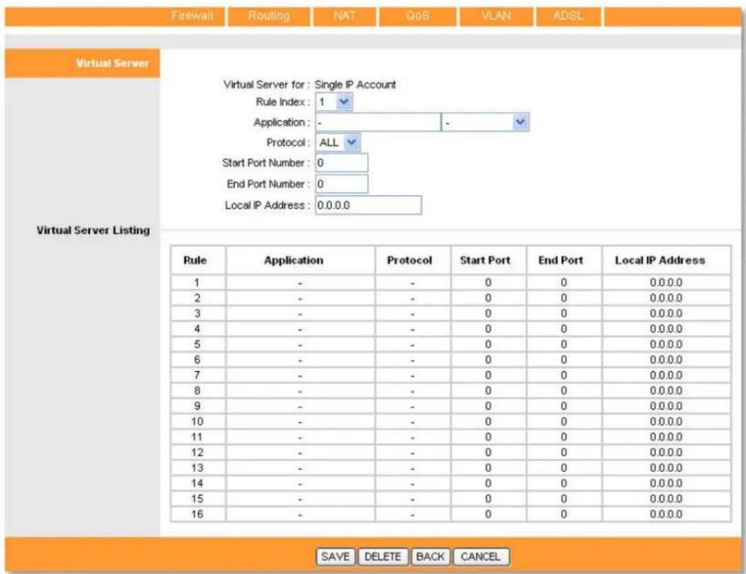
text_image
Firewall Routing NAT QoB VLAN ADSL Virtual Server Virtual Server for: Single IP Account Rule Index: 1 Application: - - - - Protocol: ALL Start Port Number: 0 End Port Number: 0 Local IP Address: 0.0.0.0 Virtual Server Listing Rule Application Protocol Start Port End Port Local IP Address 1 - - - 0 0 0.0.0.0 2 - - - 0 0 0.0.0.0 3 - - - 0 0 0.0.0.0 4 - - - 0 0 0.0.0.0 5 - - - 0 0 0.0.0.0 6 - - - 0 0 0.0.0.0 7 - - - 0 0 0.0.0.0 8 - - - 0 0 0.0.0.0 9 - - - 0 0 0.0.0.0 10 - - - 0 0 0.0.0.0 11 - - - 0 0 0.0.0.0 12 - - - 0 0 0.0.0.0 13 - - - 0 0 0.0.0.0 14 - - - 0 0 0.0.0.0 15 - - - 0 0 0.0.0.0 16 - - - 0 0 0.0.0.0 SAVE DELETE BACK CANCELRule Index: The Virtual Server rule index for this VC. You can specify 10 rules maximally. All the VCs with single IP will use the same Virtual Server rules.
Application: The Virtual Servers can be used for setting up public services on your LAN.
Protocol: The protocol used for this application.
Start & End Port Number: Enter the specific Start and End Port number you want to forward. If it is one port only, you can enter the End port number the same as Start port number. For example, you want to set the FTP Virtual Server, you can set the start and end port number to 21.
Local IP Address: Enter the IP Address for the Virtual Server in LAN side.
Virtual Server Listing: This displays the information about the Virtual Servers you establish.
IP Address Mapping (for Multiple IP Service)

text_image
Advanced Quick Start Interface Setup Advanced Setup Access Management Maintenance Status Help Firewall Routing NAT QoS VLAN ADSL NAT Virtual Circuit : PVC0 NAT Status : Activated Number of IPs : ○ Single ● Multiple DMZ Virtual Server IP Address Mapping (for Multiple IP Service)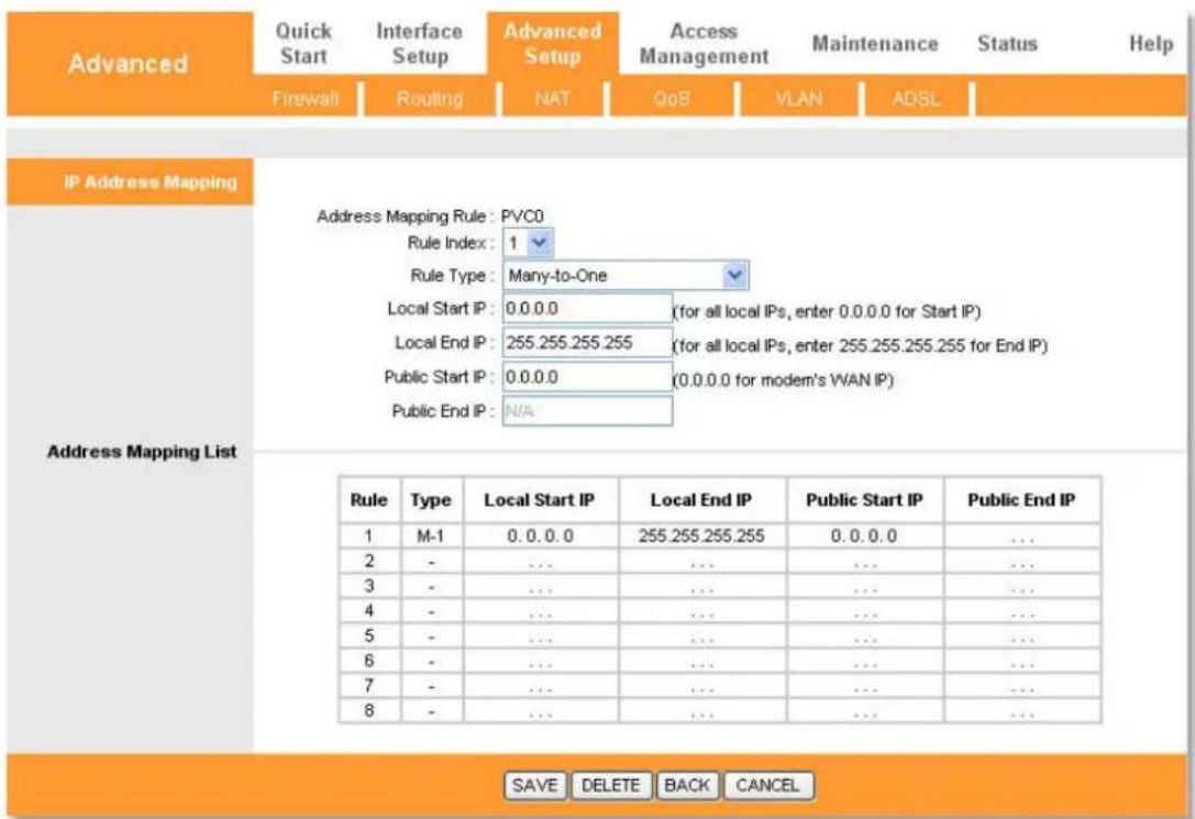
text_image
Advanced Quick Start Interface Setup Advanced Setup Access Management Maintenance Status Help Firewall Routing NAT QoS VLAN ADSL IP Address Mapping Address Mapping Rule: PVC0 Rule Index: 1 Rule Type: Many-to-One Local Start IP: 0.0.0.0 (for all local IPs, enter 0.0.0.0 for Start IP) Local End IP: 255.255.255.255 (for all local IPs, enter 255.255.255.255 for End IP) Public Start IP: 0.0.0.0 (0.0.0.0 for modern's WAN IP) Public End IP: N/A Address Mapping List Rule Type Local Start IP Local End IP Public Start IP Public End IP 1 M-1 0.0.0.0 255.255.255.255 0.0.0.0 ... 2 - ... ... ... ... ... 3 - ... ... ... ... ... 4 - ... ... ... ... ... 5 - ... ... ... ... ... 6 - ... ... ... ... ... 7 - ... ... ... ... ... 8 - ... ... ... ... SAVE DELETE BACK CANCELRule Index: Select the Virtual Server rule index for this VC. You can specify 8 rules maximally.
Rule Type: There are four types: One-to-One, Many-to-One, Many-to-Many Overload and Many-to-Many No-overload.
Local Start & End IP: Enter the local IP Address you plan to map. Local Start IP is the starting local IP address and Local End IP is the ending local IP address. If the rule is for all local IPs, then the Start IP is 0.0.0.0 and the End IP is 255.255.255.255.
Public Start & End IP: Enter the public IP Address you want to do NAT. Public Start IP is the starting public IP address and Public End IP is the ending public IP address. If you have a dynamic IP, enter 0.0.0.0 as the Public Start IP.
Address Mapping List: This displays the information about the Mapping addresses.
QoS

Quality of Service: This option will provide better service of selected network traffic over various technologies. By attaching special identification marks or headers to incoming packets, QoS determines which queue the packets enter, based priority.
QoS: Select this option to Activate/Deactivate the IP QoS on different types.
Rule: Configure the rules for QoS. If the traffic complies with the rule, then the Router will take the corresponding action to deal with it.
Rule Index: Select the index for the rule you want to configure.
Active: You can activate or deactivate this function, the rule can take effect only when it is activated.
Application: Select the application that the rule aimed at.
Physical Ports: Select the port whose traffic flow are controlled by the rule.
Destination MAC & IP & Mask & Port Range: Enter the IP information about the Destination host for the rule.
Source MAC & IP & Mask & Port Range: Enter the IP information about the Source host for the rule.
Protocol ID: Select one among TCP/UDP, TCP, UDP or ICMP protocols for the application.
Vlan ID Range: Enter the Vlan range, and the rule will be effective to the selected Vlans.
IPP/DS Field: Select the type of the action to assign the priority. When you select IPP/TOS, you can assign the priority via IP information. IP QoS function is intended to deliver guaranteed as well as differentiated Internet services by giving network resource and usage control to the Network operator.
IP Precedence Range: Enter the IP precedence range that the Router takes to differentiate the traffic.
Type of Service: Select the type of service that the Router takes to deal with the traffic.
DSCP Range: Enter the DSCP range to differentiate the traffic.
802.1p: Select the priority range for the rule. When you select DSCP, you can assign the priority via DHCP (the header of IP group). It maps the IP group into corresponding service class.

text_image
Action IPP/DS Field: ○ IPP/TOS ● DSCP IP Precedence Remarking: Type of Service Remarking: DSCP Remarking: (Value Range: 0 ~ 63) 802.1p Remarking: Queue #: ADD DELETE CANCELIP Precedence Remarking: Select the number to remark the priority for IP precedence.
Type of Service Remarking: Select the type to remark the service.
DSCP Remarking: Enter the number to remark the DSCP priority.
802.1p Remarking: Select the type to remark the 802.1p priority.
Queue: Select the priority type for the action.
VLAN
Virtual LAN (VLAN) is a group of devices on one or more LANs that are configured so that they can communicate as if they were attached to the same LAN, when in fact they are located on a number of different LAN segments. Because VLANs are based on logical instead of physical connections, it is very flexible for user/host management, bandwidth allocation and resource.
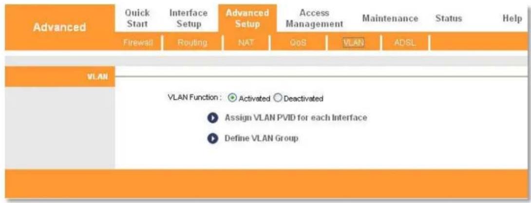
text_image
Advanced Quick Start Interface Setup Advanced Setup Access Management Maintenance Status Help Firewall Routing NAT QoS VLAN ADSL VLAN VLAN Function: ● Activated ○ Deactivated ► Assign VLAN PVID for each Interface ► Define VLAN GroupAssign VLAN PVID for each Interface.
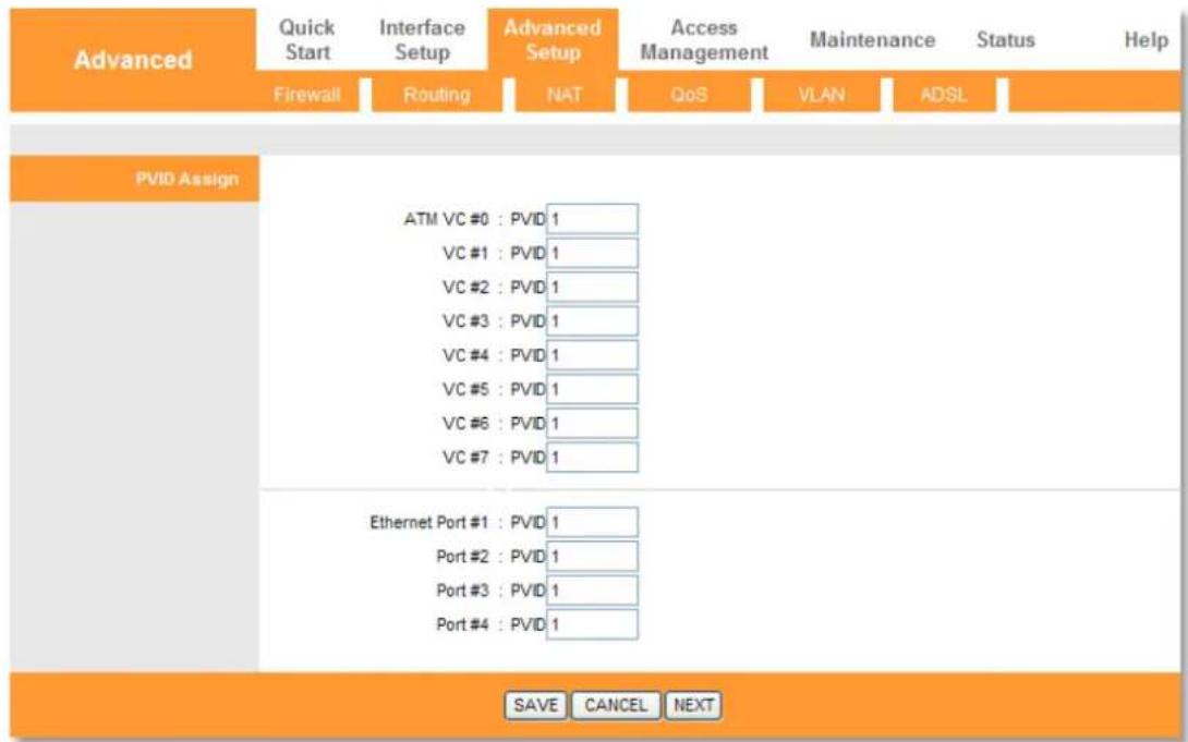
text_image
Advanced Quick Start Interface Setup Advanced Setup Access Management Maintenance Status Help Firewall Routing NAT QoS VLAN ADSL PVID Assign ATM VC #0 : PVID 1 VC #1 : PVID 1 VC #2 : PVID 1 VC #3 : PVID 1 VC #4 : PVID 1 VC #5 : PVID 1 VC #6 : PVID 1 VC #7 : PVID 1 Ethernet Port #1 : PVID 1 Port #2 : PVID 1 Port #3 : PVID 1 Port #4 : PVID 1 SAVE CANCEL NEXTPVID: Each physical port has a default VID called PVID (Port VID). PVID is assigned to untagged frames or priority tagged frames (frames with null (0) VID) received on this port.
Define VLAN Group

text_image
Advanced Quick Start Interface Setup Advanced Setup Access Management Maintenance Status Help Firewall Routing NAT QoS VLAN ADSL VLAN Group Setting VLAN Index: 1 Active: Yes No VLAN ID: 1 (Decimal) ATM VCs: Tagged Port # 0 1 2 3 4 5 6 7 Ethernet: Tagged Port # 1 2 3 4 VLAN Group Summary Group Active ID VLAN Group Ports VLAN Tagged Ports 1 Yes 1 e4,e3,e2,e1,p0,p1,p2,p3,p4,p5,p6,p7 p:pvc, e:ethernet SAVE DELETE CANCELVLAN Index: Select the VLAN index for this VC. You can specify 8 groups maximum.
VLAN ID: This indicates the VLAN group.
ATM VCs: Select the ATM VCs as members of VLAN, and if you leave the Tagged blank, the tag in frames will be deleted when transmitted from the VC.
Ethernet & USB: Select the Ethernet or USB port as a member of VLAN.
VLAN Group Summary: This displays the information about the VLAN Groups.
ADSL
The ADSL feature can be selected when you meet the physical connection problem. Please check the proper settings with your Internet service provider.

text_image
Advanced Quick Start Interface Setup Advanced Setup Access Management Maintenance Status Help Firewall Routing NAT QoS VLAN ADSL ADSL ADSL Mode: Auto Sync-Up ADSL Type: Auto Sync-Up ADSL2+ ADSL2 G.DMT T1.413 G.lite SAVE Advanced Quick Start Interface Setup Advanced Setup Access Management Maintenance Status Help Firewall Routing NAT QoS VLAN ADSL ADSL ADSL Mode: Auto Sync-Up ADSL Type: ANNEX A ANNEX A ANNEX I ANNEX A.L ANNEX M ANNEX A.K.J.M. SAVEADSL Mode: Select the ADSL operation mode which your ADSL connection uses.
ADSL Type: Select the ADSL operation type which your ADSL connection uses.
Access Management
Click any of them, and you will be able to configure the corresponding function.

flowchart
graph LR
    A["Access Management"] --> B["Quick Start"]
    B --> C["ACL"]
    C --> D["Filter"]
    D --> E["SNMP"]
    E --> F["UPnP"]
    F --> G["DDNS"]
    G --> H["CWMP"]
    H --> I["Maintenance"]
    I --> J["Status"]
    J --> K["Help"]
ACL
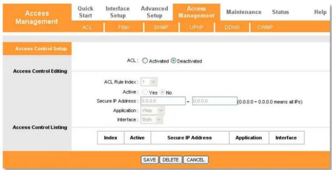
You can specify the client to access the ADSL Router once setting his IP as a Secure IP Address through selected applications.
text_image
Access Management Quick Start Interface Setup Advanced Setup Access Management Maintenance Status Help ACL Filter SNMP UPnP DDNS CWMP Access Control Setup ACL: ○ Activated ● Deactivated Access Control Editing ACL Rule Index: 1 Active: Yes ▼ No Secure IP Address: 0.0.0.0 ~ 0.0.0.0 (0.0.0.0 ~ 0.0.0.0 means all IPs) Application: Web Interface: Both Access Control Listing Index Active Secure IP Address Application Interface SAVE DELETE CANCELACL: If Activated, the IP addresses which are contained in the Access Control List can access the Modem. If Deactivated, all IP addresses can access the Modem.
ACL Rule Index: Select the ACL rule index for the entry.
Active: Enable the ACL rule.
Secure IP Address: Select the IP addresses which are permitted to access to the Router remotely. With the default IP 0.0.0.0, any client would be allowed to remotely access the Modem Router.
Application: Select the application for the ACL rule, and then you can access the Router through it.
Interface: Select the interface for access: LAN, WAN or Both.
Access Control of Listing: This displays the information about the ACL Rules.
Filter
The filtering feature includes IP/MAC Filter, Application Filter and URL Filter. The feature makes it possible for administrators to control user's access the Internet, protect the networks.

text_image
Access Management Quick Start Interface Setup Advanced Setup Access Management Maintenance Status Help ACL Filter SNMP UPnP DDNS CWMP Filter Type Filter Type Selection: IP / MAC Filter IP / MAC Filter Set Editing IP / MAC Filter Set Index: 1 Interface: PVC0 Direction: Both IP / MAC Filter Rule Index: 1 Rule Type: IP Active: Yes No Source IP Address: (0.0.0.0 means Don't care) Subnet Mask: Port Number: 0 (0 means Don't care) Destination IP Address: (0.0.0.0 means Don't care) Subnet Mask: Port Number: 0 (0 means Don't care) IP / MAC Filter Listing Protocol: TCP Rule Unmatched: Forward IP / MAC Filter Set Index 1 Interface - Direction -Active Src Address/Mask Dest IP/Mask Src Port Dest Port Protocol Unmatched
1 - - - - - - - -Filter Type Selection: Select the filter type for the configuration below.
IP/MAC Filter Rule Index: Select the Set index for the IP Filter entry. This index can match with sixteen IP / MAC Filter Rule Indexes.
Interface: Select the interface for the entry.
Direction: Select the direction for this IP/Mac Filter rule. There are three filtering directions: Both, Incoming and Outgoing.
Rule Type: You can choose IP or Mac.
Active: Select Yes to make the rule to take effect.
Source IP address & Subnet Mask & Port Number: Enter the source IP address for the rule. You can enter 0.0.0.0; it means that all IP addresses are controlled by the rule.
Destination IP Address & Subnet Mask & Port Number: Enter the destination IP address for the rule. You can enter 0.0.0.0, it means that all IP addresses are controlled by the rule. The set of Subnet Mask and Port Number are same as Source IP Address.
Protocol: TCP, UDP or ICMP in the drop-down list for the connection between the Source IP address and Destination IP address.
Rule Unmatched: If the rule is mismatch you can choose to execute the next one or stop the performance.
IP/MAC Filter Listing: This displays the information about the IP Filter rules.
SNMP
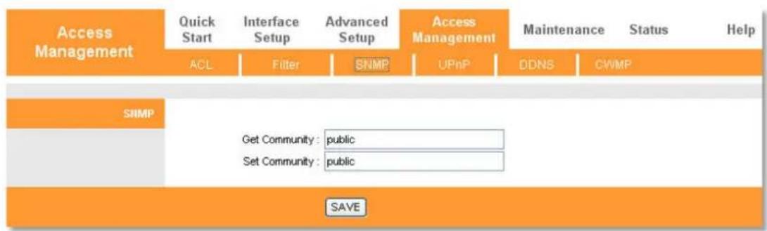
The SNMP (Simple Network Management Protocol) is used to exchange information between network devices.
flowchart
graph TD
    A["Access Management"] --> B["Quick Start"]
    B --> C["ACL"]
    C --> D["Filter"]
    D --> E["SNMP"]
    E --> F["UPnP"]
    F --> G["DDNS"]
    G --> H["CWMP"]
    I["SNMP"] --> J["Get Community : public"]
    I --> K["Set Community : public"]
    L["SAVE"] --> M["End"]
Get Community: Set password for incoming Get and get next requests from the management station.
Set Community: Set password for incoming Set and set requests from the management station.
UPnP
UPnP (Universal Plug and Play) is a distributed, open networking standard that uses TCP/IP for simple peer-to-peer network connectivity between devices. An UPnP device can dynamically join a network, obtain an IP address, convey its capabilities and learn about other devices on the network. In turn, a device can leave a network smoothly and automatically when it is no longer in use. UPnP broadcasts are only allowed on the LAN.

flowchart
graph TD
    A["Access Management"] --> B["Quick Start"]
    B --> C["ACL"]
    C --> D["Filter"]
    D --> E["SNMP"]
    E --> F["UPnP"]
    F --> G["DDNS"]
    G --> H["CWMP"]
    I["Universal Plug & Play"] --> J["UPnP: Activated ○ Deactivated"]
    I --> K["Auto-configured: Activated ○ Deactivated (by UPnP-enabled Application)"]
    L["SAVE"] --> M["End"]
UPnP: Activate or Deactivate the UPnP function.
Auto-Configured: If you activate the function, then the UPnP network devices can
automatically configure network addressing, announce their presence in the network to other UPnP devices and enable exchange of simple product and service descriptions.
DDNS
The router offers a Dynamic Domain Name System (DDNS) feature. The feature lets you use a static host name with a dynamic IP address. User should type the host name, user name and password assigned to your Modem Router by your Dynamic DNS provider. User also can decide to turn on DDNS Wildcard or not.

text_image
Access Management Quick Start Interface Setup Advanced Setup Access Management Maintenance Status Help ACL Filter SNMP UPnP DDNS CWMP Dynamic DNS Dynamic DNS: ○ Activated ● Deactivated Service Provider: www.dyndns.org My Host Name: E-mail Address: Username: Password: Wildcard support: ○ Yes ▼ No SAVEDynamic DNS: Activate the DDNS function or not.
Service Provider: This field displays the service provider of DDNS.
My Host Name: Enter your host name here.
E-mail Address: Enter your e-mail address.
Username & Password: Type the User Name and Password for your DDNS account.
Wildcard support: Select the option to use Wildcard function.
CWMP
The function supports TR-069 protocol which collects information, diagnoses the devices and configures the devices automatically via ACS (Auto-Configuration Server).

text_image
Access Management Quick Start Interface Setup Advanced Setup Access Management Maintenance Status Help ACL Filter SNMP UPnP DDNS CWMP CWMP Setup Login ACS CVMP: ● Activated ○ Deactivated URL: User Name: Password: Connection Request Path: Atr69 Port: 7547 UserName: Password: Periodic Inform Periodic Inform: ● Activated ○ Deactivated Interval(s): 86400 SAVE CANCELCWMP: Select Activated to activate the CWMP function.
URL: Enter the website of ACS which is provided by your ISP.
User Name/Password: Enter the User Name and password to login the ACS server.
Path: Enter the path that connects to the ACS server.
User Name/Password: Enter the User Name and Password that provided the ACS server to login the router.
Periodic Inform: Activate or deactivate the function. If Activated is chosen, the information will be informed to ACS server periodically.
Interval: Enter the interval time here.
Maintenance
Choose Maintenance, you can see these submenus. Click any of them, and you will be able to configure the corresponding function.

flowchart
graph LR
    A["Maintenance"] --> B["Quick Start"]
    B --> C["Administration"]
    C --> D["Time Zone"]
    D --> E["Firmware"]
    E --> F["SysRestart"]
    F --> G["Diagnostics"]
    G --> H["Status"]
    H --> I["Help"]
    style A fill:#FFD700,stroke:#333
    style I fill:#FFD700,stroke:#333
Administration

text_image
Maintenance Quick Start Interface Setup Advanced Setup Access Management Maintenance Status Help Administration Time Zone Firmware SysRestart Diagnostics Administrator Username: admin New Password: Confirm Password: SAVE CANCELNote:
- There is only one account that can access web management interface. The default account is admin, and the password is admin. Admin has read/write access privilege.
- When you change the password, you should enter the new password twice, and then click SAVE to make the new password take effect.
Time Zone
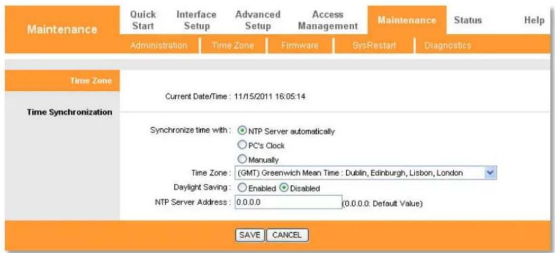
The system time is the time used by the device for scheduling services. There are three methods to configure the time. You can manually set the time, specify the PC's Clock as the device's system time or connect to a NTP (Network Time Protocol) server. If you manually set the time, you may also set Daylight Saving dates and the system time will automatically adjust to those dates. If a NTP server is set, you will only need to set the time zone. If PC's Clock is selected, the device will get the PC's Clock by way of the system time.
NTP Server automatically
Select NTP Server automatically as the synchronize time, you only need to set the time zone.
text_image
Maintenance Quick Start Interface Setup Advanced Setup Access Management Maintenance Status Help Administration Time Zone Firmware SysRestart Diagnostics Time Zone Current Date/Time : 11/15/2011 16:05:14 Time Synchronization Synchronize time with: NTP Server automatically PC's Clock Manually Time Zone: (GMT) Greenwich Mean Time : Dublin, Edinburgh, Lisbon, London Daylight Saving: Enabled Disabled NTP Server Address: 0.0.0.0 (0.0.0.0: Default Value) SAVE CANCELNote: The ADSL Router built-in some NTP Servers, when the Router connects to the Internet, the Router will get the system time automatically from the NTP Server. You can also configure the
NTP Server address manually, and then the Router will get the time from the specific Server firstly.
PC's Clock
Select PC's Clock as the synchronize time, you don't need to set any items.

text_image
Maintenance Quick Start Interface Setup Advanced Setup Access Management Maintenance Status Help Administration Time Zone Firmware SysRestart Diagnostics Time Zone Current Date/Time : 11/15/2011 16:06:31 Time Synchronization Synchronize time with: ○ NTP Server automatically ● PC's Clock ○ Manually Date: 11 / 15 / 2011 (Month/Date/Year) Time: 16 : 06 : 31 (hour:min:sec) SAVE CANCELManually
Select Manually as the synchronize time, you need to set the date and time corresponding to the current time.

text_image
Maintenance Quick Start Interface Setup Advanced Setup Access Management Maintenance Status Help Administration Time Zone Firmware SysRestart Diagnostics Time Zone Current Date/Time : 11/15/2011 16:08:28 Time Synchronization Synchronize time with: ○ NTP Server automatically ○ PC's Clock ● Manually Date : 11 / 15 / 2011 (Month/Date/Year) Time : 16 : 08 : 28 (hour:min:sec) SAVE CANCELFirmware
Make sure the firmware or romfile you want to use is on the local hard drive of the computer. Click Browse to find the local hard drive and locate the firmware or romfile to be used for upgrade.
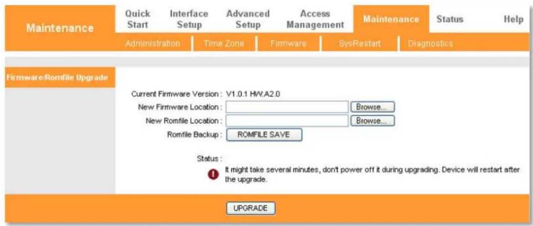
text_image
Maintenance Quick Start Interface Setup Advanced Setup Access Management Maintenance Status Help Administration Time Zone Firmware SysRestart Diagnostics Firmware/Romfile Upgrade Current Firmware Version: V1.0.1 HW.A2.0 New Firmware Location: Browse... New Romfile Location: Browse... Romfile Backup: ROMFILE SAVE Status: It might take several minutes, don't power off it during upgrading. Device will restart after the upgrade. UPGRADETo upgrade the router's firmware:
Step 1: Download a more recent firmware upgrade file.
Step 2: Type the path and file name of the update file into the 'New Firmware Location' field. Or click Browse to locate the update file.
Step 3: Click UPGRADE.
Note:
- New firmware versions are posted at www.phicomm.com and can be downloaded for free. If the router is not experiencing difficulties, there is no need to download a more recent firmware version, unless the version has a new feature that you want to use.
- When you upgrade the router's firmware, you may lose its current configurations, so please back up the router's current settings before you upgrade its firmware.
- Do not turn off the router or press the Reset button while the firmware is being upgraded.
• The router will reboot after the upgrade has been finished.
To back up the Modem Router's current settings:
Step 1: Click the ROMFILE SAVE button, you can see:

text_image
File Download - Security Warning Do you want to save this file? Name: rom-0 Type: Unknown File Type, 16.0 KB From: 192.168.1.1 Save Cancel While files from the Internet can be useful, this file type can potentially harm your computer. If you do not trust the source, do not save this software. What's the risk?Step 2: Click Save to save the file as the appointed file.

text_image
Save As Save in: Desktop My Documents My Computer My Network Places Adobe Acrobat 8 Professional Adobe Reader 9 PHICOMM Wireless FD-222 New Folder zhou 1.pdf ff.tif Phicomm PLC Utility PHICOMM Wireless LAN.exe PHICOMM Wireless LAN.rar Shortcut to HP Scanjet G2410 File name: from-0 Save as type: Document Save CancelSysRestart
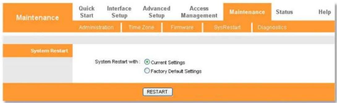
You can choose restart the device with current settings or restore to factory default settings.
flowchart
graph TD
    A["Maintenance"] --> B["Administration"]
    B --> C["Time Zone"]
    C --> D["Firmware"]
    D --> E["SysRestart"]
    E --> F["Diagnostics"]
    G["System Restart"] --> H["System Restart with: Current Settings<br>Factory Default Settings"]
    H --> I["RESTART"]
Diagnostics
You can view the test results for the connectivity of the physical layer and protocol layer for both LAN and WAN sides on the screen.
| Maintenance | Quick Start | Interface Setup | Advanced Setup | Access Management | Maintenance | Status | Help | |
| Administration | Time Zone | Firmware | SysRestart | Diagnostics | ||||
| Diagnostic Test | ||||||||
| Virtual Circuit: PVC0 | ||||||||
| >> Testing Ethernet LAN connection ... | PASS | |||||||
| >> Testing ADSL Synchronization . | FAIL | |||||||
| >> Testing ATM OAM segment ping ... | SKIPPED | |||||||
| >> Testing ATM OAM end to end ping ... | SKIPPED | |||||||
| >> Ping Primary Domain Name Server . | SKIPPED | |||||||
| >> Ping www.yahoo.com ... | SKIPPED | |||||||
Status
Choose Status, you can see these submenus: Device Info, System Log and Statistics.
Click any of them, and you will be able to configure the corresponding function.

flowchart
graph LR
    A["Status"] --> B["Quick Start"]
    B --> C["Interface Setup"]
    C --> D["Advanced Setup"]
    D --> E["Access Management"]
    E --> F["Maintenance"]
    F --> G["Status"]
    G --> H["Help"]
    I["Device Info"] --> J["System Log"]
    J --> K["Statistics"]
Device Info
You are able to view the device information, including LAN, WAN and ADSL. The information will vary depending on the settings of the Router configured on the Interface Setup screen.
| Status | Quick Start | Interface Setup | Advanced Setup | Access Management | Maintenance | Status | Help |
| Device Info | System Log | Statistics | |||||
| Device Information | |||||||
| Firmware Version: V1.0.1 HW.A2.0 MAC Address: 34:bd:19:02:44:cc | |||||||
| LAN | IP Address: 192.168.1.1 Subnet Mask: 255.255.255.0 DHCP Server: Enabled | ||||||
| WAN | Virtual Circuit: PVC0 Status: Not Connected Connection Type: PPPoE IP Address: 0.0.0.0 Subnet Mask: 0.0.0.0 Default Gateway: 0.0.0.0 Primary DNS: 0.0.0.0 Secondary DNS: 0.0.0.0 NAT: Enabled | ||||||
| ADSL | ADSL Firmware Version: FwVer:3.16.1.0_TC3086 HwVer:T14.F7_6.0 Line State: Down Modulation: N/A Annex Mode: N/A | ||||||
| Downstream | Upstream | ||||||
| SNR Margin: | N/A | N/A | db | ||||
| Line Attenuation: | N/A | N/A | db | ||||
| Data Rate: | N/A | N/A | kbps | ||||
System Log
You can check the System Log of the Modem Router in this page.

text_image
Status Quick Start Interface Setup Advanced Setup Access Management Maintenance Status Help Device Info System Log Statistics System Log 11/15/2011 16:29:1> Last errorlog repeat 26 Times 11/15/2011 16:29:1> No DNS server available 11/15/2011 16:29:1> Last errorlog repeat 10 Times 11/15/2011 16:29:1> adjTimeTask fail: no server available 11/15/2011 16:29:1> adjtime task pause 60 seconds 11/15/2011 16:29:1> No DNS server available 11/15/2011 16:29:1> Last errorlog repeat 10 Times 11/15/2011 16:29:1> adjTimeTask fail: no server available 11/15/2011 16:29:2> adjTime task pause 60 seconds 11/15/2011 16:29:2> No DNS server available 11/15/2011 16:30:1> Last errorlog repeat 10 Times 11/15/2011 16:30:1> adjTimeTask fail: no server available 11/15/2011 16:30:1> adjtime task pause 60 seconds 11/15/2011 16:30:1> No DNS server available CLEAR LOG SAVE LOGStatistics
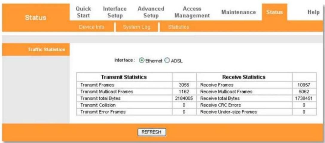
text_image
Status Quick Start Interface Setup Advanced Setup Access Management Maintenance Status Help Device Info System Log Statistics Traffic Statistics Interface: ● Ethernet ○ ADSL Transmit Statistics Transmit Frames 3056 Receive Frames 10957 Transmit Multicast Frames 1162 Receive Multicast Frames 5062 Transmit total Bytes 2184005 Receive total Bytes 1738451 Transmit Collision 0 Receive CRC Errors 0 Transmit Error Frames 0 Receive Under-size Frames 0 REFRESHInterface: You can select Ethernet and ADSL to view the corresponding network traffic over different ports.
Help
In this page, you can view the help information for configuration of any function.
| Help | Quick Start | Interface Setup | Advanced Setup | Access Management | Maintenance | Status | Help |
| Quick Start | |||||||
| ✓ Quick Start | |||||||
| Interface Setup | |||||||
| ✓ Internet Settings ✓ LAN Settings | |||||||
| Advanced Setup | |||||||
| ✓ Firewall ✓ Routing ✓ NAT ✓ QoS ✓ VLAN ✓ ADSL | |||||||
| Access Management | |||||||
| ✓ ACL ✓ IP Filter ✓ SNMP ✓ UPnP ✓ DDNS ✓ CWMP | |||||||
| Maintenance | |||||||
| ✓ Administration ✓ Time Zone ✓ Firmware ✓ SysRestart ✓ Diagnostics | |||||||
| Status | |||||||
Note: Click the tab, and you will be able to get the corresponding information.
Chapter 5: Specification
| Basic | |
| IEEE Standards IEEE802.3, IEEE802.3u | |
| Interfaces | 1 x RJ11 DSL Port, 4 x RJ45 LAN Port |
| LED Indicators | Power, LAN1-LAN4, DSL, Internet |
| Data Rate | Downstream: Up to 24Mbps, Upstream: Up to 1Mbps |
| Security | NAT and SPI Firewall, Packet Filter |
| VPN Pass Through | IPSec/PPTP/L2TP Pass-through |
| Switching Features | IGMP Snooping & IGMP Multicast, IEEE 802.1d transparent bridging |
| QoS | IP Type of service(ToS), 802.1p |
| Device Management | HTTP, TelnetAdministration and operation software (Firmware) upgradablelocally by web(HTTP) |
| ADSL | |
| ADSL Features | Full-rate ANSI T1.413 Issue 2ITU-T G.992.1 (G.dmt), ITU-T G.992.2 (G.lite)ITU-T G.994.1 (G.hs), ITU-T G.992.3 (G.dmt.bis)ITU-T G.992.5, Supports Annex A/L, Max 6 kilometers |
| ATM Features | UNI 3.1, ATM Adaptation Layer Type 5-AAL5Multiprotocol encapsulation over ATM (RFC 1483)UBR, CBR, VBR-rt, VBR-nrt, Supports 8 PVCs |
| PPP Features | PPP over ATM (RFC 2364), PPP over Ethernet (RFC 2516) |
| Others | |
| Operating Temperature | 0°C~40°C (32°F~104°F) |
| Storage Temperature | -20°C~70°C (-4°F~158°F) |
| Operating Humidity | 10%~90%, Non-condensing |
| Storage Humidity | 5%~90%, Non-condensing |
| Certifications | CE,FCC, RoHS |
| Package Contents | 1 x ADSL2/2+ Modem Router1 x Resource CD1 x Quick Installation Guide1 x Power Adapter1 x Ethernet Cable2 x Telephone Cable1 x ADSL Splitter |
Appendix A: Troubleshooting
- How do I restore my Modem Router's configuration to factory default settings?
With the router powered on, press the Reset button on the rear panel, keep holding it for about 5 seconds then release it.
- Why I cannot login the Modem Router's web management page?
• Make sure the computer goes into the LAN port of the router.
- Check the computer's IP address; make sure the IP address is obtained automatically, for details please refer to the section of Configure the Computers IP Address in this manual.
• Make sure you put 192.168.1.1 into the address bar, not the search bar.
- Check your web browser; make sure the Proxy server is unchecked. Take Internet Explorer as an example, go to Tools>Internet Options>Connections>LAN Settings, uncheck Use a proxy server for your LAN.
- If it tells you the username or password is error, and you cannot remember the new one, please reset router by pressing reset button for at least 5 seconds, and then try to login with default username and password (admin/admin).
-
What can I do if I forgot my login password for the Modem Router's web management page 192.168.1.1?
-
Restore the Modem Router to its factory default settings, please refer to question 1.
• Use the default username and password: admin, admin.
• Reconfigure the Modem Router after you reset it successfully. -
What can I do if I cannot access the Internet?
-
Make sure all the connectors are connected properly, including the telephone line, Ethernet cables and power adapter.
- Try to restart your Modem Router and computer.
- Try to login to the web management page of the Modem Router. If you can, please check the status of DSL light on the front panel of the Modem Router:
a) DSL light is solid on, please refer to question 5.
b) DSL light is blinking or off, please contact with your Internet Service Provider to check your ADSL service.
If you cannot open the Modem Router's web management page, please try to reset the Modem Router, refer to question 1.
- What can I do if the DSL light is solid on, but the Internet light is off?
Log in the Modem Router's web management page 192.168.1.1, consult your ISP and make sure
the VPI/VCI, Connection Type, username and password are correct. If there are any mistakes, please correct the settings and try again.
- How to configure PPPoE connection on Mac?
Step 1: Click the Apple menu then select System Preferences.
Step2: When the System Preferences screen appears, please go to the Internet & Wireless section and click Network.
Step 3: Under the Network screen, please select Ethernet. In the Configure IPV4 box, please select Create PPPoE Service.
Step 4: Please type the Service Name (This is optional, you should contact your ISP to confirm) and click Done.
Step 5: Type the username and the password which are from your ISP, and then please click on Apply and Connect.
Appendix B: Certification
FCC Statement

This equipment has been tested and found to comply with the limits for a Class B digital device, pursuant to part 15 of the FCC Rules. These limits are designed to provide reasonable protection against harmful interference in a residential installation. This equipment generates uses and can radiate radio frequency energy and, if not installed and used in accordance with the instructions, may cause harmful interference to radio communications. However, there is no guarantee that interference will not occur in a particular installation. If this equipment does cause harmful interference to radio or television reception, which can be determined by turning the equipment off and on, the user is encouraged to try to correct the interference by one or more of the following measures:
- Reorient or relocate the receiving antenna.
- Increase the separation between the equipment and receiver.
- Consult the dealer or an experienced radio/ TV technician for help.
- Connect the equipment into an outlet on a circuit different from that to which the receiver is connected.
FCC Caution
- Changes or modifications to this unit not expressly approved by the party responsible for compliance could void the user's authority to operate this equipment.
- This device complies with Part 15 of the FCC Rules. Operation is subject to the following two conditions: (1) This device may not cause harmful interference, and (2) this device must accept any interference received, including interference that may cause undesired operation.
CE Mark Warning
CE
Marking with the above symbol indicates compliance with the essential requirements and other relevant provisions of Directive 2004/108/EC.
This is a class B product. In a domestic environment, this product may cause radio interference, in which case the user may be required to take adequate measures.
Appendix C: Glossary
ATM (Asynchronous Transfer Mode): ATM is a cell based transfer mode that requires variable length user information to be segmented and reassembled to/from short, fixed length cells. It uses two different methods for carrying connectionless network interconnect traffic, routed and bridged Protocol Data Units (PDUs), over an ATM network.
DDNS (Dynamic Domain Name System): Allows the hosting of a website, FTP server, or e-mail server with a fixed domain name (e.g., www.xyz.com) and a dynamic IP address.
DMZ (Demilitarized Zone): Removes the Router's firewall protection from one PC, allowing it to be "seen" from the Internet.
DNS (Domain Name Server): The IP address of your ISP's server, which translates the names of websites into IP addresses.
DSL (Digital Subscriber Line): An always-on broadband connection over traditional phone lines.
Dynamic IP Address: A temporary IP address assigned by a DHCP server.
Firewall: A set of related programs located at a network gateway server that protects the resources of a network from users from other networks.
ISP (Internet Service Provider): A company that provides access to the Internet.
Ping (Packet Internet Groper): An Internet utility used to determine whether a particular IP address is online.
PPPoE (Point to Point Protocol over Ethernet): PPPoE stands for Point to Point protocol over Ethernet; this protocol is used as a type of broadband connection that provides authentication (username and password) in addition to data transport.
PPPoA (Point to Point Protocol over ATM): PPPoA stands for Point to Point protocol over ATM; this protocol is also used as a type of broadband connection that provides authentication (username and password) in addition to data transport.
Static IP Address: A fixed address assigned to a computer or device that is connected to a network.
TCP (Transmission Control Protocol): A network protocol for transmitting data that requires acknowledgement from the recipient of data sent.
UDP (User Datagram Protocol): A network protocol for transmitting data that does not require acknowledgement from the recipient of the data that is sent.
VCI (Virtual Channel Identifier): The identifier of the VC contained in the ATM cell header.
VPI (Virtual Path Identifier): The identifier of the VP contained in the ATM cell header.
VLAN (Virtual Local Air Network): Logical subgroups that constitute a Local Area Network (LAN). This is done in software rather than defining a hardware solution.
PHICOMM
Shanghai Feixun Communication Co., Ltd.
E-mail: support@phicomm.com
Website: www.phicomm.com
Copyright © 2011 Shanghai Feixun Communication Co., Ltd. All rights reserved.