USER MANUAL VSX-C502 PIONEER
Operating Instructions
Mode d'emploi
IMPORTANT

The lightning flash with arrowhead symbol, within an equilateral triangle, is intended to alert the user to the presence of uninsulated "dangerous voltage" within the product's enclosure that may be of sufficient magnitude to constitute a risk of electric shock to persons.
CAUTION
RISK OF ELECTRIC SHOCK DO NOT OPEN
CAUTION:
TO PREVENT THE RISK OF ELECTRIC SHOCK,DO NOT REMOVE COVER (OR BACK).NO USER-SERVICEABLE PARTS INSIDE.REFER SERVICING TO QUALIFIED SERVICE PERSONNEL.

The exclamation point within an equilateral triangle is intended to alert the user to the presence of important operating and maintenance (servicing) instructions in the literature accompanying the appliance.
D3-4-2-1_En
Thank you for buying this Pioneer product.
Please read through these operating instructions so you will know how to operate your model properly. After you have finished reading the instructions, put them away in a safe place for future reference.
In some countries or regions, the shape of the power plug may sometimes differ from that shown in the explanatory drawings. However, the method of connecting and operating the unit is the same.
WARNING
This equipment is not waterproof. To prevent a fire or shock hazard, do not place any container filed with liquid near this equipment (such as a vase or flower pot) or expose it to dripping, splashing, rain or moisture. D3-4-2-1-3_A_En
This product complies with the Low Voltage Directive (73/23/EEC, amended by 93/68/EEC), EMC Directives (89/336/EEC, amended by 92/31/EEC and 93/68/EEC). D3-4-2-1-9a_En
WARNING
Before plugging in for the first time, read the following section carefully.
The voltage of the available power supply differs according to country or region. Be sure that the power supply voltage of the area where this unit will be used meets the required voltage (e.g., 230V or 120V) written on the rear panel. D3-4-2-1-4_A_En
WARNING
To prevent a fire hazard, do not place any naked flame sources (such as a lighted candle) on the equipment. D3-4-2-1-7a_A_En
VENTILATION CAUTION
When installing this unit, make sure to leave space around the unit for ventilation to improve heat radiation (at least 20cm at top, 50cm at rear, and 10cm at each side).
WARNING
Slots and openings in the cabinet are provided for ventilation to ensure reliable operation of the product, and to protect it from overheating. To prevent fire hazard, the openings should never be blocked or covered with items (such as newspapers, table-cloths, curtains) or by operating the equipment on thick carpet or a bed. D3-4-2-1-7b_A_En
CAUTION
The STANDBY/ON switch on this unit will not completely shut off all power from the AC outlet. Since the power cord serves as the main disconnect device for the unit, you will need to unplug it from the AC outlet to shut down all power. Therefore, make sure the unit has been installed so that the power cord can be easily unplugged from the AC outlet in case of an accident. To avoid fire hazard, the power cord should also be unplugged from the AC outlet when left unused for a long period of time (for example, when on vacation). D3-4-2-2-a_A_En
This product is for general household purposes. Any failure due to use for other than household purposes (such as long-term use for business purposes in a restaurant or use in a car or ship) and which requires repair will be charged for even during the warranty period.
K041 En
Operating Environment
Operating environment temperature and humidity: +5^ - +35^ (+41^ - +95^) ; less than 85% RH (cooling vents not blocked)
Do not install this unit in a poorly ventilated area, or in locations exposed to high humidity or direct sunlight (or strong artificial light) D3-4-2-1-7c_A_En
If the AC plug of this unit does not match the AC outlet you want to use, the plug must be removed and appropriate one fitted. Replacement and mounting of an AC plug on the power supply cord of this unit should be performed only by qualified service personnel. If connected to an AC outlet, the cut-off plug can cause severe electrical shock. Make sure it is properly disposed of after removal. The equipment should be disconnected by removing the mains plug from the wall socket when left unused for a long period of time (for example, when on vacation). D3-4-2-2-1a_A_En
Before you start
Checking the supplied accessories
Please check that you've received the following supplied accessories:
- Microphone
- Mic stand
- SR+miniplug cable
- AM loop antenna
FM wire antenna
- Power cable
- Dry cell batteries (AA Size / IEC R6P) x2
Remote control unit
- Operating instructions
- Speaker cable labels
Warranty card
Loading the batteries
The remote control operates on two AA batteries (supplied).


Caution
- Incorrect use of batteries may result in such hazards as leakage and bursting. Observe the following precautions:
- Never use new and old batteries together.
- Insert the plus and minus sides of the batteries properly according to the marks in the battery case.
- Batteries of the same shape may have different voltages. Do not use different batteries together.
- When disposing of used batteries, please comply with governmental regulations or environmental public institution's rules that apply in your country or area.
Ventilation
- When installing this unit, make sure to leave space around the unit for ventilation to improve heat dispersal (at least 20cm at the top, 50cm at the rear, and 10cm at each side). If not enough space is provided between the unit and walls or other equipment, heat will build up inside, interfering with performance and/or causing malfunctions. See below for exceptions to this.
- Don't place anything on top of the receiver except for a Pioneer DV-464, 360, 454, 350, 444, 470, 545, 565A or 575A DVD player. If you do place one of these pieces of equipment on top of the receiver be sure to leave the ventilation space over it as prescribed above.
- If using a rack to hold the receiver make sure the back of the rack and the left side are open.
- Also, if you're using a case with doors, leave the doors open when using the receiver.
- Do not place on a thick carpet, bed, sofa or fabric having a thick pile. Do not cover the receiver with fabric or other covering. Anything that blocks ventilation will cause the internal temperature to rise, which may lead to breakdown or fire hazard.

- The receiver may become hot while in use, please take care around it.
Maintenance of external surfaces
- Use a polishing cloth or dry cloth to wipe off dust and dirt.
- When the surfaces are dirty, wipe with a soft cloth dipped in some neutral cleanser diluted five or six times with water, and wrung out well, and then wipe again with a dry cloth. Do not use furniture wax or cleansers.
- Never use thinners, benzine, insecticide sprays or other chemicals on or near this unit, since these will corrode the surfaces.
Contents
Before you start
Checking the supplied accessories 3
Loading the batteries 3
Ventilation 3
Maintenance of external surfaces 3
01 Quick start guide
Introduction 6
Easy Setup. 6
Connecting speakers 6
Connecting your TV and DVD player 7
Switching on and playing a DVD 7
Introduction to home theater 8
Features. 8
03 Connecting your equipment
Rear panel 9
The AV Direct mode. 10
Installing the receiver. 10
When making cable connections 10
Connecting a DVD player 11
Connecting your TV 12
Connecting a satellite/cable receiver or other set-top
box. 13
Connecting other video components 14
Connecting equipment to the front panel inputs . . . 15
Installing your speaker system 15
Connecting the speakers 16
Placing the speakers 16
Connecting antennas 17
AM loop antenna 17
FM wire antenna 17
Connecting external antennas. 17
Using this receiver with a Pioneer plasma display . . 18
Operating other Pioneer components with this
unit's sensor 19
Plugging in the receiver 19
04 Controls and displays
Front panel. 20
Display. 21
Remote control 22
Operating range of the remote control. 23
05 Getting started
Automatically calibrating your listening area
(MCACC) 24
MCACC error messages 25
Other problems when using MCACC 25
Checking the settings on your DVD (or other)
player. 25
Playing a source. 26
06 Home theater sound
Playing multichannel sources. 27
Playing stereo sources 27
Listening with headphones 28
Using the Advanced Surround effects 28
Using the Sound Modes 28
Enhancing dialog 28
Using the surround back channel. 29
Listening with virtual surround back speakers . . .29
07 Using the tuner
Finding a station 30
RF attenuator mode 30
MPX mode 30
Tuning directly to a station 30
Memorizing station presets 30
Naming station presets 31
Listening to memorized station presets 31
Radio Data System (RDS). 31
Displaying RDS information 32
Searching for RDS programs 32
Enhanced Other Network (EON) 33
Program identification function 33
08 Using other functions
Selecting the input signal type 34
Using the sleep timer 34
Resetting the system 35
Default receiver settings. 35
Making receiver settings from the System Setup menu 36
Setup menu options. 36
SR+ control for Pioneer plasma displays. 39
Using the SR+ mode with a Pioneer plasma display 39
Setting individual channel levels 40
10 Controlling other equipment
Using the remote control with other components...41
Recalling preset codes 42
Resetting all remote control settings 42
VCR/DVD/LD player and DVD recorder controls 43
Cable TV / satellite TV / digital TV / TV controls . . . 44
Preset code list. 45
Troubleshooting 46
Surround sound formats 49
Dolby Digital 49
Dolby Digital Surround EX. 49
Dolby Pro Logic IIx and Dolby Surround 49
DTS Digital Surround 50
DTS-ES 50
DTS Neo:6 50
DTS 96/24 50
PCM (Pulse Code Modulation) 50
Specifications 50
Chapter 1
Quick start guide
Introduction
This 'Quick start guide' shows you how to connect your speakers, TV and DVD player to this receiver, and also takes you through switching on and playing a DVD disc.
Easy Setup
This section shows you how to connect your speakers, subwoofer, DVD player and TV to this receiver so you can start enjoying home cinema sound right away.
Before you start, make sure everything you're connecting is switched off and unplugged.
Connecting speakers
This receiver has speaker terminals for front left and right speakers (L and R in the diagram), a center speaker (C), two surround speakers (RS and LS) and a surround back speaker (SB). The minimum speaker configuration is just the front left/right speakers, but we recommend connecting all five if possible. Note that surround speakers should always be connected as a pair; do not connect just one surround speaker. All the speakers you use should have a nominal impedance between 6-16Ω.
1 Connect your speakers to the receiver, as shown in the diagram below.
Prepare the speaker cable by stripping about 1 cm of the plastic shielding from each speaker wire.

Connect the front speakers to the FRONT L/R terminals; the center speaker to the CENTER terminals; the surround speakers to the SURROUND L/R terminals; and the surround back speaker to the SURROUND BACK terminals.
Press on a tab to open a terminal; insert the exposed wire, then release the tab to secure.
For correct sound it's important that the positive and negative terminals of the receiver and each speaker are matched. To help you do this, attach the supplied colored self-adhesive labels to one half of each speaker cable.
2 Connect a powered subwoofer to the SUBWOOFER OUT jack, as shown in the diagram below.
Use a standard audio cable with RCA/phono plugs.

Connecting your TV and DVD player
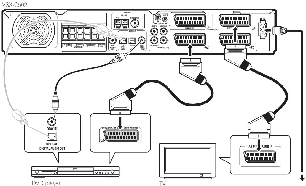
1 Connect your DVD player to the receiver.
Connect a 21-pin SCART cable (not supplied) between the AV output of your DVD player and the DVD IN AV connector of this receiver for the video and analog audio. (See Specifications on page 50 for the pin assignment.)
For digital audio, connect a coaxial digital audio cable (not supplied) between your DVD player's coaxial digital output and the DVD(STB) COAX jack on this receiver.
- If your DVD player doesn't have a coaxial digital out you can use an optical cable connected between the optical output jack on your DVD player and the STB(DVD) OPT1 jack on this receiver. However, you
will have to reassign the input to DVD before using for the first time. See Optical input setting on page 38 for how to do this.
- If you connect an optical digital cable, be careful when inserting the plug not to damage the shutter protecting the optical socket.
2 Connect your TV to the receiver.
Use a 21-pin SCART cable (not supplied) to connect the DVR/TV IN/OUT AV connector on this receiver to a SCART input on your TV.
3 Connect the supplied AC power cable to the AC IN on this receiver and plug in the other end to a power outlet.
Switching on and playing a DVD
Once you switch the receiver on it will automatically detect the speakers you have connected. Although there are a number of more detailed settings you can make to optimize the surround sound, you should be able to get acceptable surround sound performance right away.
1 Switch on your TV and powered subwoofer. Also make sure that your TV is set to the AV input you connected the receiver to.
2 Press RECEIVER on the remote or STANDBY/ON on the front panel to switch on the receiver.
3 Press DVD on the remote or turn the INPUT SELECTOR knob on the front panel to select the DVD input.
4 Switch on your DVD player.
5 Load a DVD and start playback.
This receiver will automatically decode Dolby Digital, DTS, or Dolby Surround DVD-Video discs, according to your speaker setup. In most cases, you won't have to make changes for realistic surround sound.
Other possibilities (like listening to a CD with multichannel surround sound) are explained in Home theater sound on page 27.
6 Use the MASTER VOLUME control (front panel or remote) to adjust the volume.
- Turn down your TV's volume so that you only hear sound from this system.
Introduction to home theater
You are probably used to using stereo equipment to listen to music, but may not be used to home theater systems that give you many more options (such as surround sound) when listening to soundtracks.
Home theater refers to the use of multiple audio tracks to create a surround sound effect, making you feel like you're in the middle of the action or concert. The surround sound you get from a home theater system depends not only on the speakers you have set up in your room, but also on the source and the sound settings of the receiver.
DVD-Video has become the basic source material for home theater due to its size, quality, and ease of use. The true multichannel audio possible using DVD is what creates a convincing surround sound effect and gives you the feeling of 'being there'.
Features
Dolby Digital and DTS decoding, including Dolby Digital EX, DTS 96/24 and DTS-ES (pages 27, 49, 50)
Dolby Digital and DTS decoding brings theater sound right into your home with up to six channels of surround sound, including a special LFE (Low Frequency Effects) channel for deep, realistic sound effects.
With the addition of a surround back speaker, you can take advantage of the built-in Dolby Digital EX and DTS-ES decoders for seven channel surround sound.
Multichannel analog inputs (page 11)
The addition of multichannel analog inputs means total compatibility with DVD-Audio and other high-resolution formats, as well as giving you the option of using an external decoder for Dolby Digital and DTS sources.
Dolby Pro Logic IIx and DTS Neo:6 decoders
pages 27,49,50
The built-in Dolby Pro Logic IIx and DTS Neo:6 decoders not only provide full surround sound decoding for Dolby Surrounding sources, but will also generate convincing surround sound for any stereo source.
SR + operation with Pioneer plasma displays
(page 18)
If you have a Pioneer plasma display you can take advantage of the SR + features, such as automatic input switching with the receiver and on-screen displays for receiver information.
Surround and Advanced Surround modes
(pages 27, 28)
Used together with the Dolby Digital, DTS or Dolby Pro Logic IIx modes, the Surround and Advanced Surround modes are designed to enhance particular types of program material by, for example, reproducing the acoustic space of a concert hall for music-based material.
Dialog Enhancement (page 28)
Use the Dialog Enhancement feature to accentuate dialog and vocals in a program source and match the vertical placement of the center channel with the front left/right channels.
Sound Modes (page 28)
The Sound Modes offer useful effects for a number of situations. For example, Midnight mode is useful when you need to listen at low volume but still want effective surround sound.
Easy-to-use remote control
The remote control gives you not only complete control over every function of this receiver, but also over other components in your home theater system. Using a system of preset codes, you can program the remote to operate a wide range of other equipment.
Easy setup (page 24)
Setting up for home theater sound is as easy as connecting your speakers, a DVD player or other source, and your TV. The MCACC (Multichannel Acoustic Calibration) system quick but accurate surround sound setup, while for complete surround sound control you still have access to the full range of surround sound settings.
The Energy-saving Design
This unit is designed to use less than 0.4W of energy when the receiver is in standby mode.
Manufactured under license from Dolby Laboratories. "Dolby", "Pro Logic", "Surround EX" and the double-D symbol are trademarks of Dolby Laboratories.
"DTS", "DTS-ES Extended Surround", "Neo:6" and "DTS 96/24" are trademarks of Digital Theater Systems, Inc.
Chapter 3
Connecting your equipment
Rear panel


Important
- Before making or changing the connections, switch off the power and disconnect the power cable from the power outlet.
1 SPEAKERS terminals (page 15)
FRONT L/R, CENTER, SURROUND L/R and SURROUND BACK speaker terminals.
2 Antenna connections
AM LOOP (page 17)
Connect the supplied AM loop antenna or an outdoor antenna if reception is bad.
FM UNBAL 75 antenna terminal (page 17)
Connect the supplied FM wire or an outdoor antenna if reception is bad.
3 CONTROL IN jack / CONTROL OUT jack
Use to link Pioneer components together to enable all components in the chain to use just one remote control sensor (page 19).
Also used for special SR+ control of Pioneer plasma displays (page 18).
4 SCART AV connectors
The four SCART-type AV connectors carry video and analog audio.
VIDEO IN/OUT AV connector (page 14)
AV connector for the VIDEO input. When the receiver is set to any other input, that signal is output from theVIDEO IN/OUT AV connector.
DVR/TV IN/OUT AV connector (pages 12, 14)
AV connector for the DVR/TV input. When the receiver is set to any other input, that signal is output from the DVR/TV IN/OUT AV connector.
DVD IN AV connector (page 11)
AV connector for the DVD input.
STB IN AV connector (page 13)
AV connector for the STB input.
The table on the following page shows the input and output video formats available for each AV connector.
| Connector | Input | Output |
| DVD | Composite, S-video, RGB | - |
| STB | Composite, S-video, RGB | - |
| VIDEO | Composite, S-video, RGB | Composite |
| DVR/TV | Composite | Composite, S-video, RGB |

Note
- All AV connectors also have audio in. The VIDEO and DVR/TV connectors also have audio out.
- The VIDEO and DVR/TV connectors are compatible with i/o-Link.A, T-V Link, Easy Link, MegaLogic, SMARTLINK, Q-Link, DATALOGIC, NextTView Link, etc.
5 SUBWOOFER OUT jack (page 15)
Connect a powered (active) subwoofer.
6 Digital connections
The three digital audio jacks are all inputs. Connect to the digital outputs of digital source components such as DVD and CD players, satellite receivers, etc.
STB(DVD) OPT1 jack (page 13)
Optical digital audio jack for the STB input (although it is possible to reassign it to the DVD input).
DVR/TV OPT2 jack (page 14)
Optical digital audio jack for the DVR/TV input.
- When connecting optical cables, be careful when inserting the plug not to damage the shutter protecting the optical socket.
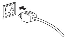
- When storing optical cable, coil loosely. The cable may be damaged if bent around sharp corners.
DVD(STB) COAX jack (page 11)
Coaxial digital audio jack for the DVD input (although it is possible to reassign it to the STB input).
7 AUDIO IN (5.1CH) jacks (page 11)
Multichannel analog audio inputs, mainly for use with multichannel DVD-Audio discs, and some DVD-Video discs that do not allow multichannel digital output.
8 ACIN (page 19)
Connect the supplied AC power cable.
The AV Direct mode
The AV Direct mode allows the receiver to pass audio/video signals arriving at one of the AV connector inputs to the AV connector outputs without the sound being output through the speakers connected to the receiver. This allows you to operate your other components as if they were connected directly to each other without the receiver being on. One use for this is if you want to record from your satellite receiver to your VCR (both connected to this receiver) without the receiver being switched on. You could also use the AV Direct mode to watch a video, using your TV's speakers for the audio, without switching on the receiver.
You can switch into AV Direct mode (from either standby or on) using the AV DIRECT button on the remote control. However, it's also possible to set the receiver to switch the AV Direct function on automatically when an incoming signal is detected. See also AVDirect setting on page 38.
The diagram below shows how the AV DIRECT and the 6 STANDBY/ON buttons switch the receiver between standby, AV Direct mode, and on.

Installing the receiver
- When installing this unit, make sure to put it on a secure and level plane that is stable.
- Don't place it on the following places:
- on a color TV (the screen may distort)
- near a cassette deck (or close to a device that gives off a magnetic field). This may interfere with the sound.
- in direct sunlight
- in damp or wet areas
- in extremely hot or cold areas
- in places where there is a vibration or other movement
- in places that are very dusty
- in places that have hot fumes or oils (such as a kitchen)
When making cable connections
Be careful not to arrange cables in a manner that bends the cables over the top of this unit. If the cables are laid on top of the unit, the magnetic field produced by the transformers in this unit may cause a humming noise to come from the speakers.

Connecting a DVD player
Follow the instructions below, referring to the diagram, to connect a DVD player.
If your DVD player has multichannel analog audio outputs you can connect them to the AUDIO IN (5.1CH) jacks on this receiver. Connecting these can be useful as some discs do not allow digital output from the player. It can also be useful if you want to use an external digital decoder unit.
1 Use a SCART cable to connect the DVD in AV connector to an AV connector on your DVD player.
2 If your DVD player has multichannel analog outputs, connect these to the SURROUND L / R, CENTER and SUBWOOFER jacks on this receiver.
These connections are shown in 2 in the illustration below.
3 Use a coaxial digital audio cable to connect the DVD(STB) COAX jack to a coaxial digital audio output on your DVD player.
This connection carries stereo and multichannel digital audio.
If your DVD player doesn't have a coaxial digital audio out jack, it is possible to use an optical connection to the STB(DVD) OPT1 jack. However, since by default this input is assigned to the STB input, you will need to reassign it to the DVD input before you can use it. After connecting up everything else see Optical input setting on page 38 for how to do this.

Note
- To listen to multichannel analog audio you'll need to switch the input signal selector to DVD 5.1ch (multichannel analog). See Selecting the input signal type on page 34.

Connecting your TV
This page shows you how to connect your TV to the receiver. If your TV has a built-in digital decoder, you can connect the digital audio output to this receiver to enjoy Dolby Digital and DTS sound from digital TV broadcasts.
1 Use a SCART cable to connect the DVR/TV IN/OUT AV connector to an AV connector on your TV.
2 Use an optical digital audio cable to connect the STB(DVD) OPT1 jack to an optical digital audio output on your TV.
If your TV doesn't have an optical digital audio out jack, it is possible to use a coaxial connection to the DVD(STB) COAX jack. However, since by default this input is assigned to the DVD input, you will need to reassign it to the STB input before you can use it. After connecting up everything else see Optical input setting on page 38 for how to do this.

Connecting a satellite/cable receiver or other set-top box
Satellite and cable receivers, and terrestrial digital TV tuners are all examples of so-called 'set-top boxes'.
1 Use a SCART cable to connect the STB IN AV connector to an AV connector on the set-top box component.
This carries video and analog stereo audio signals from the set-top box component to this receiver.
2 Use an optical digital audio cable to connect the STB(DVD) OPT1 jack to an optical digital audio output on the set-top box component.
This connection carries stereo and multichannel digital audio.
If your set-top box component doesn't have an optical digital audio out jack, it is possible to use a coaxial connection to the DVD(STB) COAX jack. However, since by default this input is assigned to the DVD input, you will need to reassign it to the STB input before you can use it. After connecting up everything else see Coaxial input setting on page 38 for how to do this.

Note
- If your satellite/cable receiver doesn't have a digital audio output, omit step 2 above.
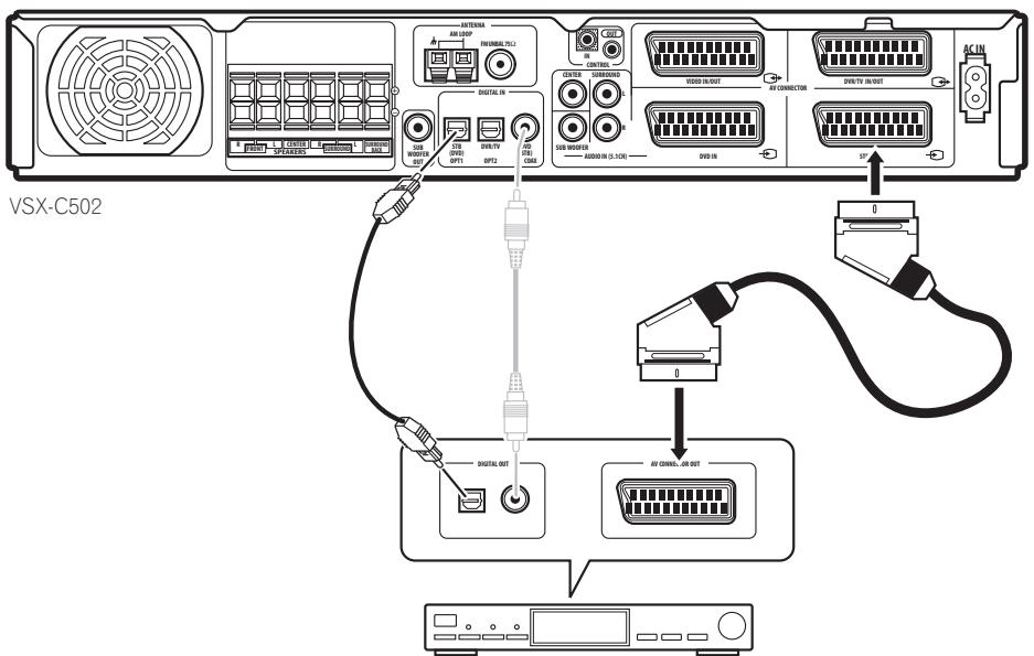
STB
Connecting other video components
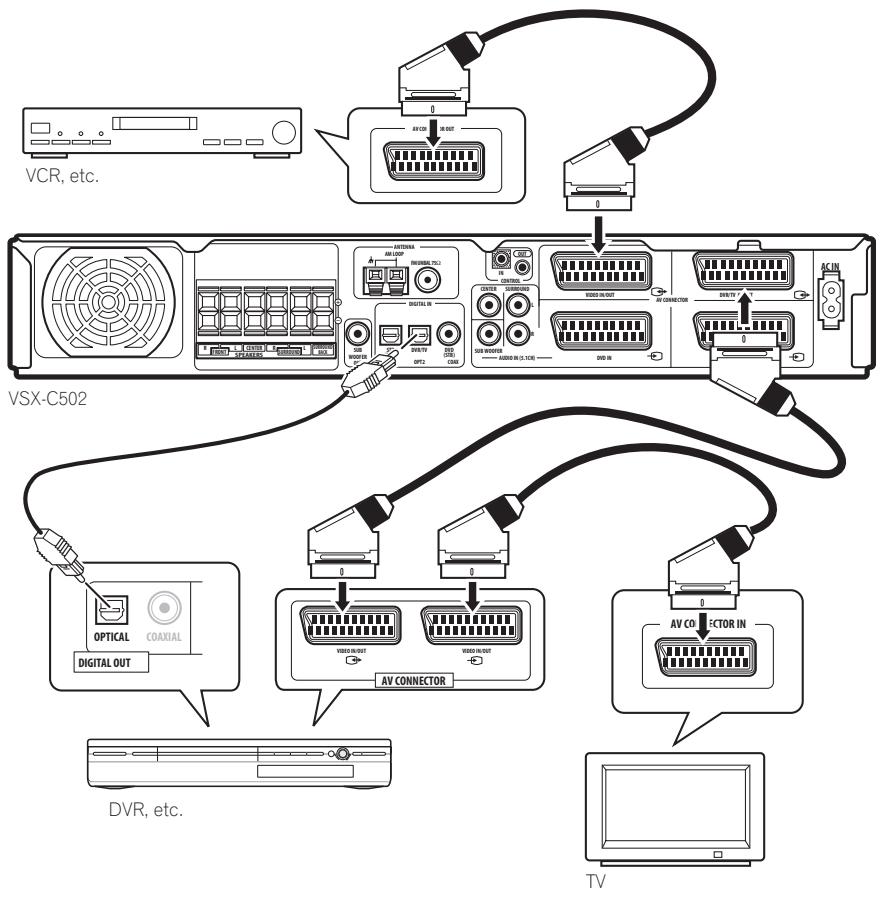
TheVIDEO IN/OUT AV connector can be used for a VCR or other video player or recorder with analog audio. The DVR/TV IN/OUT AV connector and associated digital audio connection (the DVR/TV OPT2 jack) can be used with digital video components, such as a DVD recorder, that can play digital soundtracks.
1 Use a SCART cable to connect the VIDEO IN/OUT AV connector to an AV connector on your VCR (or other video component).
This allows playback from and recording to the VCR (or other component).
2 Use a SCART cable to connect the DVR/TV IN/OUT AV connector to an AV connector on your DVD recorder (or other video component).
This allows playback from and recording to the DVR (or other component), including RGB video.
3 Use an optical digital audio cable to connect the DVR/TV OPT2 jack to an optical digital audio output on your DVD recorder (or other video component).
This connection carries stereo and multichannel digital audio.

Note
- Some TVs have both RGB and i/o-Link.A compatible AV connectors, or a single AV connector is switchable. See the instructions that came with your TV for more details. This receiver is compatible with both formats without the need to switch.
-
When the DVR is switched on, make sure that it is set to the correct input so that audio/video from the receiver gets passed through to the TV.
-
When the receiver is unplugged or in standby (with AV Direct off), you may be able to hear distorted sound from the VIDEO IN/OUT AV connector and the DVR/TV IN/OUT AV connector if a connected component is playing.
The FRONT INPUT jacks include a standard (composite) video jack (VIDEO), stereo analog audio inputs (AUDIO L/R) and an optical digital audio input (DIGITAL). You can use these connections for any kind of audio/video component, but they are especially convenient for portable equipment such as camcorders, video games
and portable audio/video equipment.
- Remove the cover to access the front panel jacks. (See diagram below)
- The illustration below shows example connections to a portable DVD player.

Installing your speaker system
To take full advantage of the receiver's surround sound capabilities connect front, center, surround and surround back speakers, as well as a subwoofer. Although this is ideal, other configurations with fewer speakers—no subwoofer or no center speaker, or no surround speakers, or even no surround back speaker—
will work. At the very least, front left and right speakers only are necessary. Note that surround speakers should always be connected as a pair; do not connect just one surround speaker. All the speakers you use should have a nominal impedance between 6-16Ω.

Connecting the speakers
Before you can start connecting the speakers, make sure that the speaker cable you're going to use is properly prepared with about 10mm of insulator stripped from each wire, and the exposed wire strands twisted together.
Each speaker connection on the receiver comprises a positive (+) colored, and negative (-) black terminal. For proper sound you should take care to match these up with the terminals on the speakers themselves. To assist you, use the supplied colored self-adhesive tags, affixing a tag to each end of one half of each cable. Use the tagged wire for the colored/positive terminal; use the untagged wire for the black/negative terminal. Use the different colors to help you identify which speaker cable attaches to which speaker.

Caution
- Make sure that all the bare speaker wire is twisted together and inserted fully into the speaker terminal. If any of the bare speaker wire touches the back panel it may cause the power to cut off as a safety measure.
- These speaker terminals can be under HAZARDOUS VOLTAGE. When you connect or disconnect the speaker cables, to prevent the risk of electric shock, do not touch uninsulated parts before disconnecting the power cord.
1 Connect the front left and right speakers to the FRONT L/R speaker terminals.
Release each tab as indicated, insert the speaker wire, then return the tab back to it's original position to secure.

2 Connect the center speaker to the CENTER speaker terminals.
3 Connect the surround left and right speakers to the SURROUND L/R speaker terminals.
4 Connect the surround back speaker to the SURROUND BACK speaker terminals.
5 Connect the subwoofer to the SUBWOOFER OUT jack.
Placing the speakers
Where you put your speakers in the room has a big effect on the quality of the sound. The following guidelines should help you to get the best sound from your system.
- The subwoofer can be placed on the floor. Ideally, the other speakers should be at about ear-level when you're listening to them. Putting the speakers on the floor (except the subwoofer), or mounting them very high on a wall is not recommended.
- For the best stereo effect, place the front speakers 2 - 3m apart, at equal distance from the TV.
- Install the center speaker above or below the TV so that the sound of the center channel is localized at the TV screen.
- When placing speakers near the TV, use magnetically shielded speakers to prevent possible interference, such as discoloration of the picture when the TV is switched on. If you do not have magnetically shielded speakers and notice discoloration of the TV picture, move the speakers farther away from the TV.
- If possible, install the surround speakers slightly above ear level.


Caution
- Make sure that all speakers are securely installed. This not only improves sound quality, but also reduces the risk of damage or injury resulting from speakers being knocked over or falling in the event of external shocks such as earthquakes.
Connecting antennas
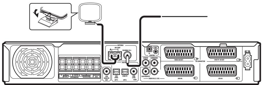
The supplied antennas provide a simple way to listen to AM and FM radio. If you find that reception quality is poor, an outdoor antenna should give you better sound quality—see Connecting external antennas below.
VSX-C502
AM loop antenna
1 Assemble the stand as shown in the illustration.

fig.A

fig.B

fig. C
- Bend the stand in the direction indicated (fig. A).
- Clip the loop into the stand (fig. B).
- It's possible to fix the AM antenna to a wall (fig. C). Before fixing, make sure that the reception is satisfactory.
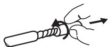
2 Pull off the protective shields of both AM antenna wires.
3 Press the AM LOOP antenna terminal tabs to open and insert one wire into each terminal.
4 Release the tabs to secure the AM antenna wires.
5 Place the AM antenna on a flat surface and point in the direction giving the best reception.
Avoid placing near computers, television sets or other electrical appliances and do not let it come into contact with metal objects.

Note
- The signal ground () is designed to reduce noise that occurs when an antenna is connected. It is not an electrical safety ground.
FM wire antenna
- Connect the FM wire antenna to the FM UNBAL 75Ω antenna terminal.
For best results, extend the FM antenna fully and fix to a wall or door frame. Don't drape loosely or leave coiled up.
Connecting external antennas
To improve FM reception connect an external FM antenna to the FM UNBAL 75Ω antenna terminal.

To improve AM reception, connect a 5-6 m length of vinyl-coated wire to the AM LOOP terminals without disconnecting the supplied AM loop antenna.
For the best possible reception, suspend horizontally outdoors.

Using this receiver with a Pioneer plasma display
If you have a Pioneer plasma display, you can use the supplied SR + cable to connect it to this receiver and take advantage of various convenient features, such as automatic video input switching of the plasma display when the input is changed.

VSX-C502

Note
- If you connect to a Pioneer plasma display using the supplied SR + cable, you will need to point the remote control at the plasma display remote sensor to control the receiver. In this case, you won't be able to control the receiver using the remote control if you switch the plasma display off.
-
This receiver is compatible with all Pioneer plasma displays from 2003 onward.
-
Use the supplied 3-ringed miniplug SR+ cable to connect the CONTROL IN jack of this receiver with the CONTROL OUT jack of your plasma display.
Before you can use the extra SR+ features, you need to make a few settings in the receiver. See Making receiver settings from the System Setup menu on page 36 for detailed instructions.

VSX-C502
To make the most of the SR+ features, you should connect your source components (DVD player, etc.) in a slightly different way to that described in this chapter. For each component, connect the video output directly to the plasma display, and just connect the audio (analog and/or digital) to this receiver.
Operating other Pioneer components with this unit's sensor
Many Pioneer components have SR CONTROL jacks which can be used to link components together so that you can use just the remote sensor of one component. When you use a remote control, the control signal is passed along the chain to the appropriate component.
Note that if you use this feature, make sure that you also have at least one set of analog audio jacks connected to another component for grounding purposes.
1 Decide which component you want to use the remote sensor of.
When you want to control any component in the chain, this is the remote sensor that you will point the remote control at.
2 Connect the CONTROL OUT jack of that component to the CONTROL IN jack of another Pioneer component.
Use a cable with a mono mini-plug on each end for the connection.
3 Continue the chain in the same way for as many components as you have.
Plugging in the receiver
Only plug in after you have connected all your components, including the speakers.

Caution
- Handle the power cable by the plug. Do not pull out the plug by tugging the cable and never touch the power cable when your hands are wet as this could cause a short circuit or electric shock. Do not place the unit or a piece of furniture, etc., on the power cable, or pinch the cable. Never make a knot in the cable or tie it with other cables. The power cables should be routed such that they are not likely to be stepped on. A damaged power cable can cause a fire or give you an electrical shock. Check the power cable once in a while. When you find it damaged, ask your nearest Pioneer authorized service center or your dealer for a replacement.
1 Plug the supplied power cable into the AC IN socket on the back of the receiver.
2 Plug the other end into a power outlet.

Tip
- You can also set up the supplied remote to control other components in your system (both Pioneer and non-Pioneer). See Using the remote control with other components on page 41 for how to do this.

Chapter 4
Controls and displays
Front panel
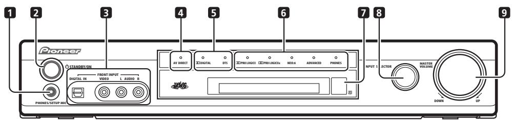
VSX-C502
1 PHONES/SETUP MIC jack
Use to connect the headphones or supplied microphone. When headphones are connected there is no sound output from the speakers.
Press to switch the receiver on or into standby.
3 FRONT INPUTacks (page 15)
Use to connect an audio/video component.
4 AV DIRECT indicator
Lights in standby when the receiver is passing an audio/video signal from one SCART AV connector to another.
DIGITAL indicator
Lights when the current source is Dolby Digital.
DTS indicator
Lights when the current source is DTS.
6 Listening mode indicators
PRO LOGIC II indicator (page 27)
Lights when one of the Dolby Pro Logic II surround modes is active with a 2 channel (stereo) source.
PRO LOGIC IIx indicator (page 27)
Lights when one of the Dolby Pro Logic IIx surround modes is active.
NEO:6 indicator (page 27)
Lights when the Neo:6 listening mode is active with a 2 channel (stereo) source.
ADVANCED indicator (page 28)
Lights when one of the Advanced Surround modes is active.
PHONES indicator (page 28)
Lights when phones surround mode is active.
7 Remote control sensor
8 INPUT SELECTOR knob (page 26)
Turn to cycle through the various inputs. The current input is shown in the front panel display.
9 MASTER VOLUME knob
Use to adjust the volume.
Display
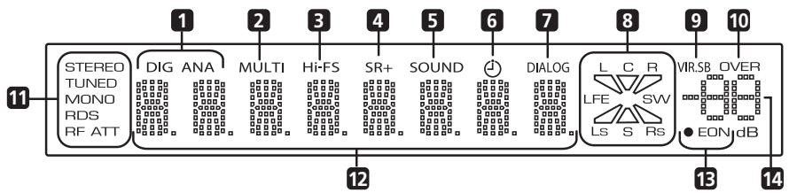
1 DIG (digital) / ANA (analog) (page 34)
Indicates whether the current input source is analog or digital.
2 MULTI indicator (page 34)
Lights when the multichannel analog inputs are selected as the input signal type for the DVD input.
3 Hi-FS indicator
Lights when the current input signal is 88.2 / 96kHz digital.
4 SR+ indicator
Lights when the Control Mode Setting is set to SR+ ON for a connected plasma display to control this receiver.
5 SOUND indicator (page 28)
Lights when one of the Sound Mode is active.
6 Sleep timer indicator (page 34)
Lights when the sleep timer has been set.
7 DIALOG indicator (page 28)
Lights when Dialog Enhancement is on.

Input indicators

Output indicators
The combined input/output indicators show at a glance which channels are present in a source and the speakers that are being used for the output.
The letters L, C, R, LFE, Ls and Rs indicate the input channels coming into the receiver (left, center, right, low frequency effect, left-surround and right-surround respectively). S lights in Dolby Surround or Surround Monoaural and LS, S, RS lights when playing Dolby EX or DTS-ES soundtracks.
The triangular segments and SW (subwoofer) indicate the active speaker output channels.
9 VIR.SB indicator (page 29)
Lights when the Virtual Surround Back effect is on.
10 OVER indicator (page 38)
Lights when the input signal is too high, risking distortion. Use the input attenuator to reduce the level.
11 Tuner indicators
STEREO (page 30)
Lights when listening to a stereo FM broadcast in auto/stereo mode.
TUNED
Lights when tuned to a broadcast.
MONO (page 30)
Lights when the tuner MPX mode is set to mono.
RDS (page 31)
Lights when listening to a station that is broadcasting RDS information.
RF ATT (page 30)
Lights when the RF attenuator is switched on.
12 Character display
13 EON indicators (page 33)
EON lights when EON is set. The dot indicator to the left lights when the current broadcast carries the EON data service.
14 Volume level indicator
Indicates the volume level in dB.
Remote control
Function names printed in green on the remote control are receiver-related functions. Function names printed in blue are for the built-in tuner (see Using the tuner on page 30). Other functions relate to other equipment that you can control using this remote. See also Controlling other equipment on page 41.
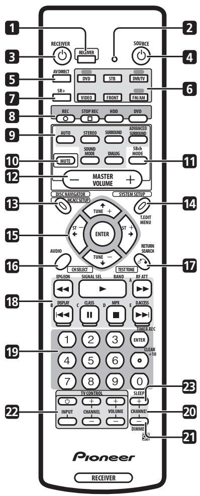
1 RECEIVER
Press to put the remote in 'receiver' mode (i.e., the remote controls the receiver functions).
2 LED
Indicates a remote control operation.
3 RECEIVER
Press to switch the receiver on or into standby.
4 SOURCE (page 41)
Press to switch the current source component on or into standby.
5 AV DIRECT (page 10 and page 38)
Press to switch the AV Direct function on / off.
6 Input/remote control mode select buttons (page 26)
When the Remote Direct function is set to on, these buttons (except FM/AM) change the remote mode and the receiver input simultaneously. When set to off, they only switch the remote mode (see also Resetting all remote control settings on page 42).
DVD
Press to select DVD as the current input.
STB
Press to select STB (set-top box) as the current input.
DVR/TV
Press to select DVR/TV as the current input.
VIDEO
Press to selectVIDEO as the current input.
FRONT
Press to select FRONT (the front panel audio/video inputs) as the current input.
FM/AM
Press to select FM/AM (the built-in tuner) as the current input.
7 SR+ (page 39)
Switches the SR+ mode on/off.
When set up, these buttons can be used to control a Pioneer DVD recorder.
REC
Press to start recording.
STOPREC
Press to stop recording.
HDD
Press to switch the recorder to HDD playback/ recording.
DVD
Press to switch the recorder to DVD playback/ recording.
AUTO (page 27)
Press to select the AUTO (default) sound for the current source (stereo, Dolby Digital, DTS, etc.) and switch off all other sound processing.
STEREO (page 27)
Press to hear the current source in stereo.
SURROUND (page 27)
Use to select a SURROUND mode for the current source.
Use to select a SOUND MODE for the current source.
DIALOG (page 28)
Press to switch on/off DIALOG (dialog enhancement).
10 MUTE
Press to mute all output. Press again (or adjust the volume using the MASTER VOLUME control) to restore the sound.
11 SBch MODE (page 29)
Use to select the surround back channel mode and virtual surround back options.
12 MASTER VOLUME
Use to adjust the volume.
13 MCACC SETUP (page 24)
Press to start MCACC (Multichannel Acoustic Calibration) setup.
14 SYSTEM SETUP (page 36)
Press to access the SYSTEM SETUP menu to make detailed receiver settings.
15 Cursor keys and ENTER
Use to navigate menus and select options/execute commands.
16 CH SELECT (page 40)
First press RECEIVER, then press CH SELECT repeatedly to select a speaker channel to adjust.
17 TEST TONE (page 40)
First press RECEIVER, then press TEST TONE to start/stop the test tone.
18Playback controls (page 43)
Playback controls for external components, such as DVD and CD players.
Functions printed in blue control the built-in tuner; other functions control other external equipment.
19 Number buttons (page 43)
Use for numerical input of track numbers, radio frequencies, and so on.
20 CHANNEL + / - (page 43)
Use to change channels on a satellite receiver, cable box, VCR or DVR.
21 DIMMER
First press RECEIVER, then press DIMMER repeatedly to change the brightness/switch off the front panel display. The display will light brightly for about two seconds when you operate the receiver with the display off or dimmed. (Note that the master volume indicator always remains lit, even when the rest of the display is off.)
22 TV CONTROL buttons (page 41)
Use to control your TV (after setting up the remote control to work with your TV).
23 SLEEP (page 34)
First press RECEIVER, then press SLEEP repeatedly to put the receiver into sleep mode and select the length of time before the receiver turns off.
Operating range of the remote control
The remote control may not work properly if:
- There are obstacles between the remote control and the receiver's remote sensor.
- Direct sunlight or fluorescent light is shining onto the remote sensor.
- The receiver is located near a device that is emitting infrared rays.
- The receiver is operated simultaneously with another infrared remote control unit.

Chapter 5 Getting started
Automatically calibrating your listening area (MCACC)
The Multichannel Acoustic Calibration (MCACC) system measures the acoustic characteristics of your listening area, taking into account ambient noise, speaker size and distance, and tests for both channel delay and channel level. After you have set up the microphone provided with your system, the receiver uses the information from a series of test tones to optimize the speaker settings and equalization for your particular room.


Caution
- The test tones used in the MCACC setup are output at high volume.
- Make sure the microphone and speakers are not moved during the MCACC setup.
- Using the MCACC setup will overwrite any existing speaker settings in the receiver (except for the subwoofer setting - page 37).
- MCACC setup can't be used if the input signal type is set to DVD 5.1ch. Press RECEIVER then SIGNAL SEL to change the input signal type to DIG or ANA.
1 If the receiver is off, press RECEIVER to turn the power on.
Also turn on your subwoofer if you have one. If headphones are connected to the receiver, disconnect them.
2 Place the microphone at your normal listening position.
Place the microphone so that it's about ear level at your normal listening position using the supplied microphone stand on a table or chair.
Make sure there are no obstacles between the speakers and the microphone.
- Don't plug the microphone into the receiver yet!
3 Press RECEIVER.
4 Press MCACC SETUP.
MIC IN blinks in the display prompting you to connect the microphone. (Open the front panel cover to access the PHONES/SETUP MIC jack.)
- MIC IN blinks in the display for about 30 seconds. If you don't connect the microphone in that time, the receiver automatically exits the MCACC setup.
After connecting the microphone the receiver will output some test tones to determine the speakers present in your setup. Try to be as quiet as possible while it's doing this.
If the background noise level is too high, NOISY! blinks in the display for five seconds, then the display shows GO
NEXT? To continue press ENTER, or press MCACC
SETUP to exit. If you choose to continue, there's a possibility that the MCACC setup may not complete successfully, resulting in an error message.
See below for notes regarding high background noise levels and an explanation of error messages.
5 Confirm the speaker configuration shown in the display.
The configuration shown in the display should reflect the actual speakers you have. Use the table below to check that it's correct.
( = Connected)
| Display | Front | Center | Surr. | Surr. Back | Sub W. |
| 2.0ch | ● | | | | |
| 2.1ch* | ● | | | | ● |
| 3.0ch | ● | ● | | | |
| 3.1ch* | ● | ● | | | ● |
| 4.0ch | ● | | ● | | |
| 4.1ch* | ● | | ● | | ● |
| 5.0ch | ● | ● | ● | | |
| 5.1ch* | ● | ● | ● | | ● |
| 6.0ch | ● | ● | ● | ● | |
| 6.1ch* | ● | ● | ● | ● | ● |
If the speaker configuration displayed isn't correct, use the / (cursor up/down) buttons to select the correct one, then press ENTER.
6 Wait while the receiver outputs more test tones to determine the optimum receiver settings.
Again, try to be as quiet as possible while this is happening.
You may have to adjust the subwoofer volume for the receiver to complete setting up.
- If the display shows SW VOL.DN, turn down the volume on the subwoofer, then press ENTER.
- If the display shows SW VOL.up, turn up the volume on the subwoofer, then press ENTER.
Once the MCACC setup has finished, the display shows COMPLETE, then RESUME.
7 When the display shows MIC OFF, disconnect the microphone.
The MCACC setup is complete!
Note that there will be no output from the speakers until you disconnect the microphone.

Note
- When one of the listening modes is selected, you can check the settings made by the MCACC system by using CH SELECT (to check channel levels) or by going through the steps in Making receiver settings from the System Setup menu on page 36 to check other settings.
- Depending on the characteristics of your room, sometimes identical speakers with cone sizes of around 12cm will end up with different size settings. You can correct the setting manually—see Making receiver settings from the System Setup menu on page 36.
MCACC error messages
Below is an explanation of error messages that can appear during MCACC setup. If you encounter an error, make the necessary checks and start the MCACC setup again.
- ERR MIC - Check the microphone connection.
- ERR Fch - Check the front speaker connections.
- ERR Sch - Check the surround or surround back speaker connections.
- ERR SW - Make sure the subwoofer has been switched on and volume on the subwoofer is turned up.
Other problems when using MCACC
If the room environment is not optimal for the auto surround setup (too much background noise, echo off the walls, obstacles blocking the speakers from the microphone) the final settings may be incorrect. Check for household appliances (air conditioner, fridge, fan, etc.), that may be affecting the environment and switch them off if necessary.
Some older TVs may interfere with the operation of the microphone. If this seems to be happening, switch off the TV when doing the auto surround setup.
Checking the settings on your DVD (or other) player
Before continuing, you may want to check the digital audio output settings on your DVD player and digital satellite receiver.
- Check that your DVD player/satellite receiver is set to output Dolby Digital, DTS and 88.2/96kHz PCM (2 channel) audio.
If there is an option for MPEG audio, set this to convert the MPEG audio to PCM.
If you connected the multichannel analog outputs of the player to this receiver, make sure that the player is set to output maultichannel analog audio.
- In addition, if you're playing a DVD disc with more than one audio track, check that you've selected the right one.

Note
- Depending on your DVD player or source discs you may not be able to output sound from other than digital 2 channel stereo and analog. In this case you need to change the listening mode to SURROUND if you want multichannel surround sound.
Playing a source
Here are the basic instructions for playing a source (such as a DVD disc) with your home theater system.
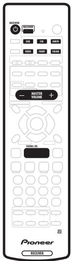

1 Turn on the power of the playback component (for example a DVD player), your TV and subwoofer (if you have one).
- If your source is the TV's built-in tuner, then switch to the channel you want to watch, otherwise make sure that the TV's video input is set to this receiver. (For example, if you connected this receiver to theVIDEO 1 jacks on your TV, make sure thatVIDEO 1 input is now selected.)
2 If the receiver isn't already on, press RECEIVER to switch it on.
You can use the front panel INPUT SELECTOR knob or Input/remote control mode select buttons on the remote.
4 Start playback of the DVD (or other component).
If you're playing a Dolby Digital or DTS surround sound DVD disc, you should hear surround sound. If you are playing a stereo source, you will only hear sound from the front left/right speakers in the default listening mode.
- See also Home theater sound on page 27 for more information on different ways of listening to sources.
5 Use MASTER VOLUME control (front panel or remote) to adjust the volume level.
- Turn down the volume of your TV so that all the sound is coming from the speakers connected to this receiver.

Note
- If you need to change the input signal type from digital to analog (stereo or multichannel), press RECEIVER then SIGNAL SEL (see also Selecting the input signal type on page 34).
- For more detailed surround sound setup, see The System Setup menu on page 36.
Chapter 6
Home theater sound
Using this receiver you can enjoy listening to sources, analog or digital, in either stereo or surround sound.

Note
- You can't use the Stereo, Surround, Advanced Surround modes or the Sound Modes when the multichannel analog inputs are selected (see also Selecting the input signal type on page 34).
- Many of the surround sound effects described in this section require surround speakers. If you don't have surround speakers connected, or they are turned off, many of the listening modes are unavailable.
Except for Dialog Enhancement and Virtual Surround Back, the current listening modes are retained for each input function (DVD, FM/AM, etc.).
Playing multichannel sources
Multichannel sources, such as DVDs and digital satellite broadcasts, can be played in multichannel surround sound, or in 2 channel stereo.
If you connected a surround back speaker, see also Using the surround back channel on page 29.
See also Using the Sound Modes on page 28, and Using the Advanced Surround effects on page 28, for further stereo and surround playback options.

- During playback of a multichannel source, press AUTO for surround sound playback.
The DIGITAL or DTS indicator on the front panel lights depending on the source format. Any active Advanced Surround mode is cancelled.
- To switch to stereo playback, press STEREO.
The STEREO indicator on the front panel lights.
Any active Advanced Surround mode is cancelled, but you can still use the Sound Modes.

Note
-
When you play a multichannel source in STEREO, all channels are mixed to the front speakers.
-
When playing 88.2/96 kHz PCM or 88.2/96 kHz DTS stereo sources, only the STEREO listening mode is available.
Playing stereo sources
Stereo sources, such as CD, FM radio and TV broadcasts, can be played in stereo, or through all your speakers using one of the various Surround modes.
If you connected a surround back speaker, see also Using the surround back channel on page 29.
See also Using the Sound Modes on page 28, and Using the Advanced Surround effects on page 28, for further stereo and surround playback options.

- During playback of a stereo source, press STEREO for stereo playback.
The STEREO indicator on the front panel lights.
Any active Advanced Surround or Pro Logic IIx mode is cancelled, but you can still use the Sound Modes.
- To play the source in surround sound, press SURROUND to select a Pro Logic II, Pro Logic IIx or Neo:6 mode.
Press repeatedly to select a Pro Logic II, Pro Logic IIx or Neo:6 mode (front panel PRO LOGIC II, PRO LOGIC IIx or NEO:6 indicator lights):
MOVIE - (Pro Logic IIx) 6.1 channel sound, especially suited to movie sources
- MUSIC - (Pro Logic IIx) 6.1 channel sound, especially suited to music sources
PROLOGIC - (Pro Logic II) 5.1 channel surround sound
CINEMA - (Neo:6) 6.1 channel sound, especially suited to movie sources
- MUSIC - (Neo:6) 6.1 channel sound, especially suited to music sources

Note
-
When playing 88.2/96 kHz PCM or 88.2/96 kHz DTS stereo sources, only the STEREO listening mode is available.
-
If the SB CH MODE is switched off, or the surround back speaker setting is S.BACK-, PRO LOGIC IIx becomes PRO LOGIC II.
- During playback of a Dolby Digital multichannel source with the SBch MODE switched ON, you will only be able to select DOLBY EX or MUSIC (Pro Logic IIx). See Using the surround back channel on page 29 for more on this.
Listening with headphones
When headphones are connected, only the STEREO (default) and PHONES SURROUND (virtual surround sound for headphones) modes are available.
When you connect a pair of headphones, the listening mode automatically changes to STEREO. When you disconnect them it reverts to the previous mode.
1 Press RECEIVER.
2 With headphones connected, press ADVANCED SURROUND to select PHONES SURROUND, or STEREO for stereo sound.
Using the Advanced Surround effects
Advanced Surround effects can be used with multichannel or stereo sources for a variety of additional surround sound effects.
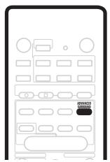
- Press ADVANCED SURROUND to select an Advanced Surround mode.
Press repeatedly to select from:
ADV.MOVIE - Gives a movie theater-type sound
ADV. MUSIC - Gives a concert hall-type sound
- TV SURR. - Designed for mono or stereo TV broadcasts and other sources
- SPORTS - Designed for sports and other programs based on commentary
- GAME - Creates surround sound from video game sources
EXPANDED - Creates an extra wide stereo field
- 6-STEREO - Designed to give powerful surround sound to stereo music sources
- VIRTUAL - Creates the impression of surround sound from just the front speakers (Sound Modes are unavailable when VIRTUAL is selected)

Note
- You can't use the Advanced Surround effects when the multichannel analog inputs (DVD 5.1ch) are selected, or when playing 88.2 / 96kHz PCM or DTS sources.
Using the Sound Modes
The Sound Modes create a variety of tonal and dynamic effects that can be used with multichannel or stereo sources.

- Press SOUND MODE to select a Sound Mode.
Press repeatedly to select from:
- OFF - No Sound Mode
- MIDNIGHT - For effective surround sound at low volume
- QUIET - Reduces the impact of deep bass and piercing highs
- BRIGHT - Adds high-end 'sparkle'
S. BASS - Adds extra power to the low-end.

Note
- You can't use the Sound Modes when the multichannel analog inputs are selected.
Enhancing dialog
- Default setting: DIALOG OFF
The dialog enhancement feature is designed to make the dialog stand out from other background sounds in a TV or movie soundtrack.

- Press DIALOG to select the amount dialog enhancement.
Press repeatedly to select from:
- DIALOG OFF - No dialog enhancement
- DIALOG ON - Dialog enhancement

Note
- You can't use the dialog enhancement feature when the multichannel analog inputs (DVD 5.1ch) are selected, or when playing 88.2 / 96kHz PCM or DTS sources.
Using the surround back channel
You can have the receiver automatically switch to Dolby Digital EX or DTS-ES decoding for 6.1 encoded sources (SB AUTO), or you can choose to listen to other kinds of sources (for example, 5.1 encoded material) with 6.1 encoding (SB ON). With 5.1 encoded sources, a surround
back channel will be generated, but the material may sound better in the 5.1 format for which it was originally encoded, in which case you can simply switch the surround back channel off (SB OFF).
The table below indicates when you will hear the surround back channel when playing various kinds of sources. (Sound plays through surround back channel speaker.)
| Type of source | SB CH mode | AUTO | | Surround | Advanced Surround* |
| MOVIE, MUSIC, PROLOGIC | NEO:6 CINEMA, NEO:6 MUSIC |
| Dolby Digital EX/DTS-ES encoded multichannel source with 6.1ch surround | ON | ● | ● | | | ● |
| AUTO | ● | ● | | | ● |
| Dolby Digital 5.1ch source | ON | ● | ● | ● | | ● |
| AUTO | | | | | ● |
| Dolby Digital/DTS encoded multichannel source | ON | ● | ● | | | ● |
| AUTO | | | | | ● |
| Dolby Digital/DTS encoded stereo source; other digital stereo source | ON | | | ● | ● | ● |
| AUTO | | | ● | ● | ● |
| Analog 2-channel (stereo) source | ON | | | ● | ● | ● |
| AUTO | | | ● | ● | ● |
- All modes except VIRTUAL mode

- Press SBch MODE repeatedly to cycle through the surround back channel options.
Each press changes the setting as follows:

Note
- If the Surround back speaker setting is set to SB —, you can only use the virtual surround back effect (see below).
- You can't hear the surround back channel with DTS 96 kHz/24-bit sources.
Listening with virtual surround back speakers
- Default setting: VIR.SB OFF
If you don't have a real surround back speaker connected, you can use the Virtual Surround Back feature to simulate one.
Note that this feature only works when the surround channels are active and the Surround back speaker setting is set to SB. See also Surround-back speaker setting on page 36.
- Press SBch MODE repeatedly to switch between VIR.SB ON and VIR.SB OFF.
Chapter 7
Using the tuner
Finding a station
The following steps show you how to tune in to FM and AM radio broadcasts using the automatic (search) and manual (step) tuning functions. If you already know the exact frequency of the station you want to listen to, see Tuning directly to a station below. Once you are tuned to a station you can memorize the frequency for recall later—see Memorizing station presets below for more on how to do this.
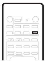

1 Press the FM/AM button on the remote control to put it in tuner mode.
2 Press BAND (or FM/AM) to change the band (FM or AM), if necessary.
Each press switches the band between FM and AM.
3 Tune to a station using the TUNE + / - buttons.
Automatic tuning
To search for stations in the currently selected band, press and hold either the TUNE + / - buttons for about a second. The receiver will start searching for the next station, stopping when it has found one. Repeat this step to search for other stations.
Manual tuning
To change the frequency one step at a time, press the TUNE + / - buttons.
High speed tuning
Press and hold the TUNE + / - buttons for high speed tuning, releasing the button once the desired frequency is reached.
RF attenuator mode
If the radio signal is too strong and/or the sound is distorting press the RF ATT button to attenuate (lower) the radio signal input and reduce the distortion (for FM stations only).
MPX mode
If there is interference or noise during a stereo FM radio broadcast (the STEREO indicator is lit), or the radio reception is weak, press MPX (remote control only) to switch the receiver into mono reception mode (the MONO indicator lights). This should improve the sound quality and allow you to enjoy the broadcast.
Tuning directly to a station
Sometimes, you'll already know the frequency of the station you want to listen to. In this case, you can simply enter the frequency directly using the number buttons on the remote control.


1 Press the FM/AM button on the remote control to put it in tuner mode.
2 Press BAND (or FM/AM) to change the band (FM or AM), if necessary.
Each press switches the band between FM and AM.
3 Press D.Access (Direct access).
4 Use the number buttons to enter the frequency of the radio station.
For example, to tune to 106.00 (FM), press 1, 0, 6, 0, 0.

Note
- If you make a mistake while inputting the frequency, press the D.Access button twice to cancel the frequency and start again.
Memorizing station presets
If you often listen to a particular radio station, it's convenient to have the receiver store the frequency for easy recall whenever you want to listen to that station. This saves the effort of manually tuning in each time. The receiver can memorize up to 30 stations, stored in three banks, or classes, (A, B and C) of 10 stations each. When memorizing FM frequencies, the receiver also stores the
MPX setting (see MPX mode on page 30) and the RF attenuator setting (see RF attenuator mode on page 30).

1 Tune to a station you want to memorize.
See Finding a station on page 30 and Tuning directly to a station on page 30 for more detail on how to do this.
2 Press T.EDIT.
The display shows ST. MEMORY then a blinking memory class (A, B or C).
3 Press CLASS to select one of the three classes.
Press repeatedly to cycle through the three memory classes, A, B and C.
Press repeatedly to cycle through the 10 available station memories in each class.
5 While the display is blinking, press ENTER.
6 Repeat steps 1-5 to memorize up to 30 stations.
Naming station presets
You can input a name of up to four characters for each preset station in the receiver's memory. For example, you could input BBC1 for that station and when you listen to it the name, rather than the frequency number, will appear in the display.
2 Press CLASS repeatedly to select the class.
Press repeatedly to cycle through the three memory classes, A, B and C.
4 Press T.EDIT to select the station name mode (ST.NAME).
Scroll through the letters, numbers and symbols, stopping on the one you want.
That character lights steadily in the display and the cursor automatically moves to the next space.
7 Enter up to three more characters in the same way.
Any time you want to exit the process you can press the T.EDIT button.
8 Press ENTER when you have got the characters you want to enter.
9 Repeat steps 2 - 6 to memorize up to 30 preset broadcast station names.

Tip
- To change a station name, just enter the new name over the top of the old one. To erase a station name, enter a new name of four spaces.
- When not in one of the RDS modes (see below), you can switch between the frequency display and the station name display using the DISPLAY button.
Listening to memorized station presets
2 Press CLASS to select the class in which the station is stored.
Press repeatedly to cycle through the three memory classes, A, B and C.
You can also use the number buttons on the remote control to recall the station preset.

Note
- If the power is left disconnected from the receiver for more than about a month, the station presets will be lost and will have to be reprogrammed.
Radio Data System (RDS)
Radio Data System, or RDS as it's usually known, is a system used by FM radio stations to provide listeners with various kinds of information—the name of the station and the kind of show they're broadcasting, for example. This information shows up as text on the display, and you can switch between the kind of information shown. Although you don't get RDS information from all FM radio stations, you do with most. Probably the best feature of RDS is that you can search automatically by type of program. So, if you felt like listening to jazz, you could search for a station that's broadcasting a show with the program type, JAZZ. There are around 30 such program types, including various genres of music, news, sport, talk shows, financial information, and so on.
The receiver lets you display three different kinds of RDS information: Radio Text (RT), Program Service Name (PS), and Program Type (PTY).
Radio Text (RT) is messages sent by the radio station.
These can be anything the broadcaster chooses—a talk radio station might give out its telephone number as RT, for example.
Program Service Name (PS) is the name of the radio station.
Program Type (PTY) indicates the kind of program currently being broadcast.
The receiver can search for and display the following program types:
NEWS - News
AFFAIRS - Current affairs
INFO - General information
SPORT-Sport
EDUCATE - Educational material
DRAMA - Radio plays or serials
CULTURE - National or regional culture, theatre, etc.
SCIENCE - Science and technology
VARIANT - Usually talk-based material, such as quiz shows or interviews.
POP M - Pop music
ROCK M - Rock music
EASY M - Easy listening music
LIGHT M - 'Light' classical music
CLASSICS - 'Serious' classical music
OTHER M - Other music not fitting any of the above categories
WEATHER - Weather
FINANCE - Stock market reports, commerce, trading, etc.
CHILDREN - Programs for children
SOCIAL-Social affairs
RELIGION - Programs concerning religion
PHONE IN - Public expressing their views by phone
TRAVEL - Holiday-type travel rather than traffic announcements
LEISURE - Leisure interests and hobbies
JAZZ-Jazz
COUNTRY - Country music
NATION M - Popular music in a language other than English
OLDIES - Popular music from the '50s and '60s
FOLK M - Folk music
DOCUMENT - Documentaries
In addition, there are three other program types, ALARM,
NO DATA and NO TYPE. ALARM used for exceptional emergency announcements. You can't search for this, but the tuner will switch automatically to this RDS
broadcast signal. NO DATA is displayed when there is no RDS data to display. NO TYPE appears when a type cannot be found.
Use the DISPLAY button to display the different types of RDS information available (RT, PS and PTY).
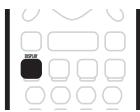
Each press changes the display as follows:
- RT - Radio Text display
- PS - Program Service display
- PTY - Program Type display
FREQ - Current tuner frequency

Note
- In the PS mode, if you have entered a station name for the currently tuned station, this is displayed rather than the RDS PS broadcast.
- In the RT mode, if any noise is picked up while displaying the text, some characters may be displayed incorrectly temporarily.
- In the RT, when no RT data is transmitted from the broadcast station, NO RADIO TEXT DATA is displayed once and after that the PS data is displayed. If you have entered a name for that station it will be displayed.
- In the PTY mode, there are cases where NO DATA is displayed. In this case the tuner will automatically switch to the PS mode after a few seconds.
- If reception conditions are strong but the RDS data is displayed incorrectly, press RF ATT.
Searching for RDS programs
One of the most useful features of RDS is the ability to search for a particular kind of radio program. You can search for any of the program types listed on the previous page—these cover all kinds of music, as well as news, weather forecasts, sports programs, and a variety of others.

1 Press SEARCH.
2 Use the / (cursor left/right) buttons to select the program type you want to hear.
3 Press ENTER to search for the program type.
The tuner searches through the FM stations stored in the station memories.
If the tuner finds a matching program type, the tuner plays 5 seconds of the station. To listen to that station, press the ENTER button. (The tuner stops searching.)
If you don't press the ENTER button during the above mentioned 5 seconds, the tuner resumes the search.
When the tuner finds a program type you searched for, the frequency display will blink for about 5 seconds and then the display will show FINISH briefly.
If NO PTY is displayed it means the tuner couldn't find that program type at the time of the search.

Note
- This function searches RDS stations preset in the 30-station memory. If there are no station presets, or if the program type could not be found among the station presets NO PTY is displayed.
Enhanced Other Network (EON)
EON (Enhanced Other Network information) allows you to set the receiver to switch automatically to a news or traffic information broadcast. Once set, the receiver will scan for stations transmitting news or traffic announcements even when it's in a different input function (DVD, for example). When the broadcast ends, the tuner returns to the original frequency or input function.
EON can only be used in areas where EON data is transmitted, and it only works with FM broadcast stations that transmit RDS program type (PTY) information.
The EON indicator lights when EON is set. The dot indicator to the left lights when the current broadcast carries the EON data service.

1 Press the FM/AM button to put the receiver in FM tuner mode.
2 Press EON to select the EON mode.
Press repeatedly to switch between:
- TA (Traffic Announcement) - Sets the tuner to pick up traffic information when it is broadcast.
- NEWS - Sets the tuner to pick up news when it is broadcast.
- OFF - Switches off the EON feature.
When set to TA or NEWS, the EON indicator in the display lights. When the receiver switches automatically to an EON broadcast, the dot indicator blinks.

Note
- The EON function does not work when listening to AM reception, or when the AV Direct function is on (see The AV Direct mode on page 10 and AV Direct setting on page 38).
- Simultaneous requests for Traffic Information (TA) and News (NEWS) is not possible.
- When EON is turned on and a function other than the tuner is selected, the function will switch to the FM station automatically when Traffic Information or News begins. When the program ends, the original function will be restored.
- You can't use the T.EDIT and SEARCH buttons while the EON indicator in the display is lit.
- You can't change the input function while receiving an EON broadcast. If you want to change to a source other than tuner, press EON and turn the EON mode to OFF.
Program identification function
The receiver will automatically register an identifying marker (called a PI code) for any station you input into the memory classes which can receive RDS or EON data. If you want to remove the currently memorized stations from RDS and EON searches, you can do it by erasing the PI codes.
1 Tune to the station for which you want to erase the PI marker.
2 Press EON for two seconds or more. ERASE PI is displayed.
3 Press ENTER within 5 seconds.
Chapter 8
Using other functions
The DVD, STB, DVR/TV and FRONT inputs all have both analog and digital jacks. You can select the type of signal to be used in each case. The DVD input has a third option; multichannel analog input.
The input signal type for the current input is indicated in the display: ANA (analog), DIG (digital), and DVD 5.1ch (multichannel analog).
The default AUTO setting is usually sufficient, letting the receiver decide the most suitable signal type. However, if you want to record from the VIDEO IN/OUT AV connector or the DVR/TV IN/OUT AV connector, then you should set the input signal type to analog.

1 Press RECEIVER.
- SEL. AUTO – (default setting) Uses digital if available, otherwise analog.
- SEL. ANA - Uses the analog signal
- SEL. DIG - Uses the digital signal
- SEL. 5.1ch - Uses the multichannel analog signal (only selectable for the DVD input)

Note
- When the VIDEO or FM/AM inputs are used, the display always shows ANA (analog).
-
When DVD 5.1ch (multichannel analog) is selected, only the volume and channel level settings are applied to the sound; you cannot use the Stereo, Surround, Advanced Surround modes, Sound Modes and dialog enhancement. (If you want to use these, select DIG (digital) as the input signal type.
-
MCACC setup is not usable when DVD 5.1ch is selected. Switch to one of the other settings if you want to use MCACC setup.
Using the sleep timer
The sleep timer automatically puts the receiver into standby after the specified period of time.
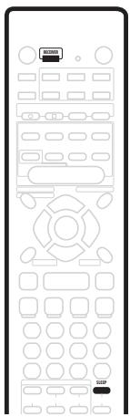
1 Press RECEIVER.
2 Press SLEEP to set the sleep timer.
Press repeatedly to select between:
- 90 MIN. - Switches to standby after 90 minutes
- 60 MIN. - Switches to standby after one hour
- 30 MIN. - Switches to standby after 30 minutes
The sleep timer indicator (♂) lights when the sleep timer has been set.

Note
- The sleep timer is cancelled if you switch on the AV Direct function. See alsoThe AV Direct mode on page 10 and AV Direct setting on page 38.

Tip
- Press the SLEEP button once to view how much time is left on the timer before shutdown. Each press after that will cycle through the possible sleep time lengths.
Resetting the system
Use this feature to reset the system to its factory default settings.

1 Press RECEIVER.
2 In standby, press MCACC SETUP and SYSTEM SETUP at the same time.
The display prompts you to confirm.
3 Within 5 seconds, press
The display shows OK?
4 Within 5 seconds, press .
The receiver should now be reset.

Note
- If the receiver is disconnected from the power outlet for more than a month it will reset to the default settings.
- The above reset doesn't affect the presets that you have programmed into the remote control (see Using the remote control with other components on page 41).
Default receiver settings
The table below shows the factory default settings. When you reset the system, the receiver reverts to these defaults.
| Setting type | Default setting | Page ref. |
| Input | DVD | |
| Master volume | ---- dB (no sound) | |
| Listening mode | AUTO (all inputs) | Page 27 |
| Listening mode (w/ headphones) | STEREO (all inputs) | Page 28 |
| Sound mode | OFF | Page 28 |
| Dialog | OFF | Page 28 |
| Surround Back Channel mode | ON (When speaker is connected) | Page 29 |
| Input signal select | AUTO | Page 34 |
| Speakers (front, center, surround, surround back) setting | Automatically sensed | Page 36 |
| Subwoofer setting | 200 Hz | Page 37 |
| LFE Attenuator | 0 dB | Page 37 |
| Speaker distance settings | Front left/right: 2.0 mCenter: 2.0 mSurround left/right: 2.0 mSurround Back: 2.0 mSubwoofer: 2.0 m | Page 37 |
| Dynamic Range Control | OFF | Page 37 |
| Dual Mono | ch1 | Page 38 |
| Input Attenuator | OFF (all inputs) | Page 38 |
| DVD(STB) COAX jack assignment | DVD | Page 38 |
| STB(DVD) OPT1 jack assignment | STB | Page 38 |
| Channel levels | Front: 0 dBCenter: 0 dBSurround: 0 dBSurround Back: 0 dBSubwoofer: 0 dB | Page 40 |
| AV Direct setting | MANUAL | Page 38 |
| Auto Input Select setting | MANUAL | Page 38 |
| SR+ mode | OFF | Page 39 |

Note
- The default settings for the remote control to control other components can be found in Using the remote control with other components on page 41.
Chapter 9
This receiver allows you to make detailed settings to optimize the surround sound performance. You only need to make these settings once (unless you change the placement of your current speaker system or add new speakers).

1 If the receiver isn't already on, press RECEIVER to switch it on.
2 Press RECEIVER.
3 Press SYSTEM SETUP to enter the setup menu.
4 Use the and buttons to select a setup parameter to adjust.
As you scroll through the options, the current settings are displayed. See below for a full list and description of each.
5 Use the and buttons to change the current setting.
6 After making all the settings, press ENTER to exit the setup menu.
Below are all the available settings in the setup menu. The first setting in each section is the default. See also the notes in each section for additional information about the settings.
Front speakers setting
Specifies the size of the front speakers:
- FRONT S - Small (the cone diameter is less than 12 cm)
- FRONT L - Large (the cone diameter is 12cm or greater)
Center speaker setting
Specifies the size of the center speaker:
- CENTER S - Small (the cone diameter is less than 12 cm)
- CENTER L - Large (the cone diameter is 12 cm or greater)
- CENTER — – If you have not connected a center speaker
Surround speaker setting
Specifies the size of the surround speakers:
- SURREN. S - Small (the cone diameter is less than 12 cm)
- SURR. L - Large (the cone diameter is 12 ~cm or greater)
- SURR. — If you have not connected surround speakers

Note
- If the front speakers are set to FRONT S you can't choose SURR. L for the surround speakers or CENTER L for the center speaker.
Surround-back speaker setting
Specifies the size of the surround-back speaker:
- S.BACK S - Small (the cone diameter is less than 12 cm)
S.BACK L-Large (the cone diameter is 12cm or greater)
- S.BACK — – If you have not connected a surroundback speaker

Note
- If the surround speakers are set to SURR. S you can't choose S.BACK L for the surround back speaker. If the surround speakers are set to SURR. —, only S.BACK — can be selected for the surround back speaker.
Subwoofer setting
This option only appears if you have connected a subwoofer. Note that some subwoofer settings are not available depending on other speaker settings.
Specifies the behavior of the subwoofer:
- SUBWF 200 - Most of the bass frequencies are played through the subwoofer
- SUBWF 150 - Mid setting
- SUBWF 100 - Only the very lowest bass frequencies are played through the subwoofer
- SUBWF —— No sound from the subwoofer
- SUBWF PLS - For extra bass power

Note
- The SUBWF PLS setting is only available when the front speakers are set to FRONT L.
- When all speakers are set to L, you cannot select the SUBWF 200, or SUBWF 150 settings.
- If you set the front speakers to FRONT S, you cannot select the SUBWF — setting.
- Depending on the source and other receiver settings, you may not always hear sound from the subwoofer.
LFE attenuator setting
Dolby Digital and DTS audio sources include ultra-low bass tones. Set the LFE attenuator as needed to prevent the ultra-low bass from distorting the sound.
- LFEATT 0 - The LFE channel is played with no attenuation
LFEATT10-LFE channel is attenuated by 10 dB
- LFE OFF - LFE channel is not played
Front-left speaker distance setting
Specifies the distance from your listening position to the front-left speaker:
- L 0.1 m. - L 9.0 m. - Distance can be set in increments of 0.1 m. The default is 2.0 m.
Center speaker distance setting
Specifies the distance from your listening position to the center speaker:
- C 0.1 m. - C 9.0 m. - Distance can be set in increments of 0.1 m. The default is 2.0 m.
Front-right speaker distance setting
Specifies the distance from your listening position to the front-right speaker:
- R 0.1 m. - R 9.0 m. - Distance can be set in increments of 0.1 m. The default is 2.0 m.
Right-surround speaker distance setting
Specifies the distance from your listening position to the surround-right speaker:
- RS 0.1 m. - RS 9.0 m. - Distance can be set in increments of 0.1 m. The default is 2.0 m.
Surround-back speaker distance setting
Specifies the distance from your listening position to the surround-back speaker:
- SB 0.1 m. - SB 9.0 m. - Distance can be set in increments of 0.1 m. The default is 2.0 m.
Left-surround speaker distance setting
Specifies the distance from your listening position to the left-surround speaker:
- LS 0.1 m. - LS 9.0 m. - Distance can be set in increments of 0.1 m. The default is 2.0 m.
Subwoofer distance setting
Specifies the distance from your listening position to the subwoofer:
- SW 0.1 m. - SW 9.0 m. - Distance can be set in increments of 0.1 m. The default is 2.0 m.
Dynamic Range Control
Specifies the amount of dynamic range adjustment to Dolby Digital or DTS soundtracks:
- DRC OFF - No dynamic range adjustment (use when listening at higher volume)
- DRC MAX - Dynamic range is reduced (loud sounds are reduced in volume while quieter sounds are increased)
- DRC MID - Mid setting

Note
- This setting works only with Dolby Digital or DTS soundtracks. For other sources you can create a similar effect using the Midnight mode (see Using the Sound Modes on page 28).
Dual mono setting
Specifies how dual mono encoded Dolby Digital or DTS soundtracks should be played:
- ch1 - Only channel 1 is played
- ch2 - Only channel 2 is played
- L. c1 R. c2 - Both channels are played through the front speakers

Note
- On the ch1 and ch2 settings the sound comes only from the center speaker (or from the front speakers if CENTER — was selected for the center speaker setting.
- This setting works only with dual mono encoded Dolby Digital or DTS soundtracks. See the disc packaging for channel information.
When playing analog sources, if the sound is distorting (or when you see the OVER indicator light in the display), switch on the input attenuator. Each input has its own attenuator setting; set it for the currently selected input.
IN. ATT OFF - Input attenuator is off
IN. ATT ON - Input attenuator is on
Specifies which receiver function the coaxial input (DVD(STB) COAX jack) relates to:
COAX DVD - Assigns the input to the receiver's DVD function
- COAX STB - Assigns the input to the receiver's STB function (the optical input is automatically set to DVD)

Note
See also Connecting your equipment on page 9.
Specifies which receiver function the optical input (STB(DVD) OPT1 jack) relates to:
- OPT1 STB - Assigns the input to the receiver's STB function
- OPT1 DVD - Assigns the input to the receiver's DVD function (the coaxial input is automatically set to STB)

Note
See also Connecting your equipment on page 9.
- You cannot assign the other optical input (DVR/TV OPT2 jack).
AV Direct setting
The AV Direct mode allows the receiver to pass audio/video signals arriving at one of the AV connector inputs to the other AV connector outputs without the sound being routed to the speakers. (See also The AV Direct mode on page 10.) In AV Direct mode, the current input is shown (at reduced brightness) in the front panel display.
The AV Direct setting determines whether the receiver switches to AV Direct mode automatically, or only when you switch it manually.
- AVD MANU - Allows you to switch between standby and AV Direct mode using the AV DIRECT button on the remote control.
- AVD AUTO - Automatically switches to AV Direct mode when an incoming signal is sensed by the receiver in standby.
Specifies how the receiver responds when it senses that a component connected to one of the SCART AV connectors is switched on.
- SEL MANU - You must select the receiver's input manually using the front panel INPUT SELECTOR, or the input buttons on the remote control.
- SEL AUTO - When a component connected to one of the SCART AV connectors (except the DVR/TV) is switched on, the receiver automatically switches to that input.

Note
- When set to AVD AUTO, if a connected component is switched on, you cannot switch this receiver into standby (INPUT ON appears in the display).
- You can't use the sleep timer when the AV Direct setting is AVD AUTO (see also Using the sleep timer on page 34).
- When AV Direct is on, EON is switched off (see also Enhanced Other Network (EON) on page 33).
SR + control for Pioneer plasma displays
Make the following settings if you have connected a Pioneer plasma display to this receiver using the supplied SR + cable. Note that the number of function settings available will depend on the plasma display you've connected.
See also Using this receiver with a Pioneer plasma display on page 18 and Using the SR+ mode with a Pioneer plasma display on page 39.
Volume control setting
VOL C OFF - The receiver does not control the volume of the plasma display
VOLC ON - When the receiver is switched to one of the inputs that use the plasma display (DVD, or another one of functions listed below), the volume on the plasma display is muted so only sound from the receiver is heard.
- DVD:1 – DVD:5 or TV – Matches the DVD function of the receiver with a numbered video input on the plasma display. For example, DVD:3 matches the DVD input with video input 3 on the plasma display.
- STB:1 - STB:5 or TV - Matches the STB function of the receiver with a numbered video input on the plasma display. For example, STB:1 matches the STB input with video input 1 on the plasma display.
- DVR:1 – DVR:5 or TV – Matches the DVR/TV function of the receiver with a numbered video input on the plasma display. For example, DVR:2 matches the DVR/TV input with video input 2 on the plasma display.
-VIDEO:1 -VIDEO:5 or TV -Matches theVIDEO function of the receiver with a numbered video input on the plasma display. For example,VIDEO:TV matches theVIDEO input with TV on the plasma display.
- FRONT:1 - FRONT:5 or TV - Matches the FRONT function of the receiver with a numbered video input on the plasma display. For example, FRONT:4 matches the FRONT input with video input 4 on the plasma display.

Note
- You won't be able to control the input if you switch the function setting off (- shows in the display), even if the SR+ feature is switched on.
Using the SR+ mode with a Pioneer plasma display
When connected using the supplied SR+ cable, a number of features become available to make using this receiver with your Pioneer plasma display even easier. These features include:
- On-screen displays when making receiver settings, such as speaker setup, MCACC setup, and so on.
- On-screen volume display.
- On-screen display of listening mode.
Automatic video input switching on the plasma display.
Automatic volume muting on the plasma display. (When VOL CON is selected.)
See also Using this receiver with a Pioneer plasma display on page 18 for connecting up, and SR+ control for Pioneer plasma displays on page 39 for setting up the receiver.
1 Make sure that the plasma display and this receiver are switched on and that they are connected with the SR+ cable.
See Using this receiver with a Pioneer plasma display on page 18 for more on connecting these components.

Caution
- The SR+ setting remains in effect even if the power is switched off.
- The automatic volume muting feature is enabled separately; see SR+ control for Pioneer plasma displays on page 39.
Setting individual channel levels
Use to set the relative volume of each channel as you find necessary for balanced surround sound.

1 Use MASTER VOLUME to adjust the volume to an appropriate level.
2 Press RECEIVER then TEST TONE to output the test tone.
The test tone is output in the following order (from speakers that are switched on and are appropriate for the current listening mode):
L-Front left
C Center
R-Front right
RS - Right surround
- SB-Surround back
LS - Left surround
- SW - Subwoofer
3 Use the / (cursor up/down) buttons to adjust speaker levels so that you hear the test tone at the same volume from each speaker when seated in your main listening position.
The channel level range is ± 10 dB.
4 Press RECEIVER then TEST TONE to turn off the test tone.

Note
- Since the subwoofer transmits an ultra-low frequency its sound may seem quieter than it actually is. Be careful not to turn up your subwoofer too much and check the volume with an actual source.
- The subwoofer volume is best controlled with the volume control on the subwoofer unit itself.
- The speaker volume can be adjusted without outputting the test tone by pressing CH SELECT then using the 1 / 4 (cursor up/down) buttons. This level setting mode is automatically exited after 5 seconds of inactivity.
-
The default setting is 0 dB for all channels.
-
You cannot use the test tone when the multichannel analog inputs (DVD 5.1ch) are selected, or when playing 88.2 / 96kHz PCM or 96/24 DTS sources.
Chapter 10
Controlling other equipment
Using the remote control with other components
The supplied remote control can operate not only this receiver, but also your TV, DVD player and other components, once you've programmed it with the appropriate preset code.
When you select an input (DVD, STB, DVR/TV, VIDEO, FRONT or FM/AM), you change both the receiver's input source and the remote control mode (see also Resetting all remote control settings on page 42). Some buttons on the remote have different functions depending on the current mode of the remote.
The TV CONTROL buttons are dedicated to controlling the TV. They will always control the TV no matter what operation mode the remote is in. Similarly, the DVD recorder controls (REC ●, STOP REC ☐, HDD and DVD)
The default preset codes are shown in the table.
| Input/remote control mode select button | Preset code | Component (manufacturer) |
| DVD | 020 | DVD (Pioneer) |
| STB | 200 | STB (Pioneer) |
| DVR/TV | 466 | DVD recorder (Pioneer) |
| VIDEO | 231 | TV (Pioneer) |
| FRONT | 100 | LD (Pioneer) |
| FM/AM | 500 | Tuner (Pioneer) |
| TV CONTROL | 600 | TV (Pioneer) |

1 SOURCE
According to the current remote mode, switches an external component on or into standby.
Changes the receiver input and also the mode of the remote control.
Dedicated buttons for controlling a Pioneer DVD recorder.
Buttons used only for controlling receiver functions.
The function of a particular button varies according to the remote control mode and the type of component being controlled. (Some buttons also control receiver functions.)
Dedicated buttons for controlling your TV.
Recalling preset codes
The following steps show you how to recall preset codes for each input and for the TV CONTROL buttons.
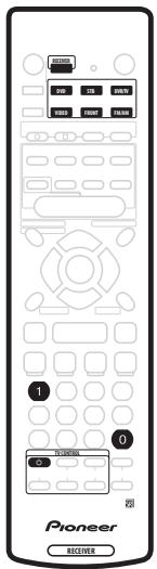
The LED starts blinking.
- To cancel the preset mode at any time press RECEIVER.
- The remote control will also return to the previous mode after one minute of inactivity.
- To preset the TV CONTROL buttons, press TV CONTROL .
The LED stops blinking and remains lit.
See Preset code list on page 45 for a list of all the codes of different types of equipment.
The LED starts blinking again.
After entering a code, a power on/off command is transmitted by the remote. If the component you want to control can be switched on/off by remote, it should now switch on/off.
If the other component fails to switch on/off, try another preset code if there is one available.
4 Repeat process to assign preset codes for as many components as you want.

Note
- See Preset code list on page 45 for the components and manufacturers available.
- The preset codes cover a wide variety of equipment, however, there may be some models from a particular manufacturer that do not work with any of the available codes.
- With some components, not all functions are controllable by this remote.
- Refer to VCR / DVD / LD player and DVD recorder controls on page 43 and Cable TV / satellite TV / digital TV / TV controls on page 44 for detailed information on the function of individual buttons.
Resetting all remote control settings
This restores all presets to the factory defaults. See Using the remote control with other components on page 41 for the default remote settings.
The LED on the remote control blinks three times indicating all the preset codes setting have been reset to the factory defaults.
VCR / DVD / LD player and DVD recorder controls
This remote control can control these components after entering the proper codes (see Using the remote control with other components on page 41).
Note that in addition to the controls listed in this table, there are dedicated controls on the remote for a Pioneer DVD recorder.
| Button(s) | Function | Components |
| SOURCE | Press to switch the components between standby and on. | A// |
| ← | Press to return to the start of the current track or chapter. | A// |
| → | Press to advance to the next track or chapter. Repeated presses skips to the start of the following tracks or chapters. | A// |
| II | Press to pause playback or recording. | A// |
| ▶ | Hold down for fast-forward playback. | A// |
| ← | Hold down for fast-reverse playback. | A// |
| ▶ | Press to start playback. | A// |
| ■ | Press to stop playback (on some models, pressing this when the disc is already stopped will cause the disc tray to open). | A// |
| ENTER/TIMER REC | Use as ENTER. | DVD |
| Press after keying a channel number. | VCR |
| Press to display timer recording screen. | DVD recorder (PIONEER DVR-720H, 520H, 320) |
| Press to switch sides of a disc. | LD |
| +10 ·/CLEAR | Use as +10 button when entering numbers. | LD |
| Press to clear a numeric entry. | DVD / DVD recorder |
| Number buttons | Use to directly access tracks, etc. on a program sourceMethod 1: For numbers 1-9, use the number buttons. For numbers 10 and over, use the +10 button, e.g., +10, +10, 3 for 23.Method 2: Use the number buttons followed by ENTER, e.g., 2, 3, ENTER for 23. | A// |
| REC ● & ▶ | Press together to start recording. | VCR |
| DISC NAVIGATOR | Press to display top menu. | DVD / LD |
| Press to display Disc Navigator screen. | DVD recorder (PIONEER DVR-720H, 520H, 320) |
| MENU | Press to display on-screen menu. | A// |
| RETURN | Press to go back to the previous menu page. | DVD / DVD recorder |
| AUDIO | Press to change the audio track of discs with more than one audio track. | DVD / LD / DVD recorder |
| Press to change TV/VCR. | VCR |
| ↑↓←→ , ENTER | Use to navigate on-screen menus. | A// |
| CHANNEL +/- | Use to select channels. | LD / VCR / DVD recorder |
Cable TV / satellite TV / digital TV / TV controls
This remote can control these components after entering the proper codes or teaching the receiver the commands (see Using the remote control with other components on page 41).
| Button(s) | Function | Components |
| TV ♂ | Press to switch between standby and on. | A// |
| INPUT SELECT | Press to switch the TV input. | TV |
| CHANNEL +/- | Use to select channels/pages. | A// |
| VOLUME +/- | Use to adjust the TV volume. | TV |
| VOLUME - & ENTER | Press together to mute the Pioneer TV volume. | TV (Pioneer) |
| MENU | Press to display menu screen. | A// |
| RETURN | Use to go back to the previous menu page. | TV / DTV |
| Press to exit menu. | Cable TV / Satellite TV |
| AUDIO | Use to switch audio channels. | A// |
| ←/EPG | Press to display EPG screen. | TV |
| Press to display guide screen. | Cable TV / Satellite TV / DTV |
| ► | A | Satellite TV |
| ← | Press to display previous page (Page -). | Cable TV |
| B | Satellite TV |
| RED | TV |
| BLUE | DTV |
| ►I | Press to display next page (Page +). | Cable TV |
| E | Satellite TV / DTV |
| CYAN | TV |
| YELLOW | DTV |
| II | C | Satellite TV |
| GREEN | TV / DTV |
| ■ | D | Satellite TV |
| YELLOW | TV |
| RED | DTV |
| ENTER/TIMER REC | Use as ENTER. | A// |
| Number buttons | Use to directly access TV channelsMethod 1: For numbers 1-9, use the number buttons. For numbers 10 and over, use the +10 button, e.g., +10, +10, 3 for 23.Method 2: Use the number buttons followed by ENTER, e.g., 2, 3, ENTER for 23. | A// |
| ↑↓←→, ENTER | Use to navigate on-screen menus. | A// |

Note
- Depending on the maker and individual model, there are some buttons that may not be able operate some
equipment or may operate it in a different way.
Preset code list
DVD player
| Manufacturer | Code |
| PIONEER | 000, 008, 020 |
| AKAI | 007 |
| DENON | 010 |
| HITACHI | 012 |
| JVC | 004 |
| PANASONIC | 003 |
| PHILIPS | 013 |
| RCA | 009, 011 |
| SAMSUNG | 005 |
| SHARP | 006 |
| SONY | 002 |
| SONY (PS2) | 016 |
| THOMSON | 015 |
| TOSHIBA | 001 |
| ZENITH | 014 |
DVD recorder
| Manufacturer | Code |
| PIONEER | 456, 466, 467, 468 |
| PANASONIC | 465 |
| TOSHIBA | 464 |
LD player
| Manufacturer | Code |
| PIONEER | 100, 111(DVD/LD) |
| DENON | 110 |
| HITACHI | 109 |
| PHILIPS | 104 |
| RADIOLA | 104 |
| SONY | 101, 102 |
TV
| Manufacturer | Code |
| PIONEER | 600, 651, 231 |
| ALBA | 639 |
| BUSH | 647 |
| FINLUX | 655 |
| FISHER | 635, 638 |
| FUJITSU | 648 |
| FUNAI | 640 |
| GOLDSTAR | 650 |
| GRANDIENTE | 657 |
| GRUNDIG | 631, 653 |
| HITACHI | 606, 633, 634, 654 |
| ITT | 642 |
| JVC | 613 |
| MITSUBISHI | 609 |
| NOKIA | 632, 652 |
| PANASONIC | 608, 622 |
| PHILIPS | 607, 656 |
| RCA | 618 |
| SALORA | 643 |
| SAMSUNG | 644, 646 |
| SANYO | 645 |
| SHARP | 602 |
| SONY | 604 |
| TANDY | 641 |
| TELEFUNKEN | 637 |
| THOMSON | 636 |
| TOSHIBA | 605 |
STB (satellite/CATV)
| Manufacturer | Code |
| PIONEER | 200, 204, 700 |
| JERROLD | 716 |
| SA | 706, 708 |
| ZENITH | 717 |
Digital STB
| Manufacturer | Code |
| PIONEER | 200, 204 |
VCR
| Manufacturer | Code |
| PIONEER | 400, 443 |
| AIWA | 446 |
| AKAI | 442 |
| ALBA | 447, 452 |
| BAIRD | 450 |
| BUSH | 448 |
| GOLDSTAR | 650 |
| GRADIENTE | 441 |
| GRUNDIG | 453, 454, 455 |
| HITACHI | 406 |
| JVC | 407, 428 |
| MAGNAVOX | 414 |
| MATSU | 445 |
| MITSUBISHI | 609, 424 |
| PANASONIC | 408, 432 |
| SANYO | 444 |
| SHARP | 402 |
| SONY | 416, 417, 457, 458, 459 (digital video) |
| TELEFUNKEN | 451 |
| THOMSON | 449 |
| TOSHIBA | 405 |
Tuner
| Manufacturer | Code |
| PIONEER | 500 |

Note
- There are cases where only certain functions may be controllable after assigning the proper preset code, or the codes for the manufacturer in the list will not work with the particular model you are using.
See page 41 for the default preset codes.
Chapter 11
Troubleshooting
Incorrect operations are often mistaken for trouble and malfunctions. If you think that there is something wrong with this component, check the points below. Sometimes the trouble may lie in another component. Investigate the
other components and electrical appliances being used. If the trouble cannot be rectified even after exercising the checks listed below, ask your nearest Pioneer authorized service center or your dealer to carry out repair work.
| Symptom | Cause | Remedy |
| The power does not turn on. | ·The power plug is disconnected. | ·Connect the power plug to the wall outlet. |
| ·The protection circuit may have been activated. | ·Disconnect the power plug from the outlet, and insert again. |
| ·Static electricity caused by dry air. | ·Disconnect the power plug from the outlet, and insert again. |
| ·Something is obstructing the rear panel fan. | ·Remove the obstruction then press ∅ STANDBY/ON for 10 seconds to switch on. |
| ·The internal temperature of the unit has become too high. | ·Place the unit in a cool, airy place to cool it down, then press ∅ STANDBY/ON for 10 seconds to switch on. |
| The receiver suddenly switches off. | ·The internal temperature of the unit has become too high. | ·Allow the unit to cool down in a well ventilated place, then press ∅ STANDBY/ON for 10 seconds to switch on. |
| ·The thermistor (temperature sensor) is faulty. | ·Unplug the receiver from the wall and call a Pioneer-accredited repair center. |
| ·The receiver has a serious problem. | |
| AMP ERR is displayed, then the power automatically switches off. | ·The receiver has a serious problem. | ·Unplug the receiver from the wall and call a Pioneer-accredited repair center. Do not try to switch the unit on/off again after seeing this message. |
| The unit does not respond when the buttons are pressed. | ·Improper connections. | ·Make sure the component is connected correctly (see page 9). |
| ·Sound is muted. | ·Press MUTE on the remote control. |
| ·The volume is turned down. | ·Adjust the MASTER VOLUME. |
| No sound is output when the AM/FM is selected. | ·Incorrect frequency. | ·Tune in the correct frequency. |
| ·The antenna is not connected. | ·Connect the antenna (see page 17). |
| Broadcast stations cannot be selected automatically. | ·The radio signal is too weak. | ·Connect an outdoor antenna (see page 17). |
| Considerable noise in radio broadcasts. | FM broadcasts
·The FM antenna is not fully extended or is poorly positioned. | ·Fully extend the FM wire antenna, position for best reception, and secure to a wall. |
| ·Weak radio signals. | ·Connect an outdoor FM antenna (see page 17). |
| AM broadcasts
·The AM antenna is poorly positioned. | ·Adjust the direction and position for best reception. |
| ·Weak radio signals. | ·Connect an additional internal or external AM antenna (see page 17). |
| ·Interference caused by other equipment (fluorescent lamp, motor, etc.). | ·Turn off the equipment causing the noise or move it away from the receiver. |
| ·Place the antenna farther away from the equipment causing the noise. |
| No sound from surround or center speakers. | ·Surround or center speaker settings are incorrect. | ·Refer to Making receiver settings from the System Setup menu on page 36 to check the speaker settings. |
| ·The surround and/or center levels are turned down. | ·Turn levels up. See Setting individual channel levels on page 40 to check the speaker levels. |
| ·The surround and/or center speakers are disconnected. | ·Connect the speakers (see page 15). |
| No sound from surround back speaker. | • Surround back speaker is switched off. | • Set the surround back speaker to S Back S or S.Back L (See page 36). |
| • The surround back channel is off | • Set the surround back channel to SB AUTO or SB ON (see page 29). |
| No sound from subwoofer. | • The subwoofer is disconnected or switched off. | • Connect or switch on the subwoofer (see page 15). |
| • The subwoofer's settings are incorrect. | • Set the subwoofer (see page 37). |
| • Set the front speakers to Small (S) (see page 36). |
| • The subwoofer's levels are too low. | • See Setting individual channel levels on page 40 to check the speaker levels. |
| • The LFE Attenuator is set to OFF. | • Set the LFE Attenuator to either 0 dB or 10 dB (see page 37). |
| No sound output from one speaker. | • The speaker system setting is switched off. | • Change the speaker setting to Large (L) or Small (S) (see page 36). |
| • The speaker isn't connected properly. | • Check all connections. |
| • The source has no sound output for that channel. | • If you choose one of the Advanced Surround mode, an extra channel may be created for the speaker (see page 28). |
| • The speaker output level is set too small. | • Increase the speaker output level. |
| Noise is output when scanning a DTS CD. | • The scan function performed by the player slightly alters the digital information, making it unreadable. | • This is not a malfunction, but be sure to turn the volume down to prevent the output of loud noise from your speakers. |
| The Dolby/DTS indicator doesn't light when playing Dolby/DTS software. | • The player is paused. | • Press play. |
| • The player's sound output settings are wrong. | • Set the player correctly (consult the manual that came with the player, if necessary). |
| When playing a 96 kHz/24bit disc the sound is too loud. | • Different discs have different recording levels so some may be louder than others. | • Turn the volume down. |
| The sound distorts. | • The analog signal is too strong. | • Turn on input attenuator (see page 38). |
| • Master volume is too loud. | • Turn the volume down. |
| You can only hear treble from speakers. | • The front speakers are set to small (S). | • Set the front speakers to large (L) (see page 36). |
| Sound is produced from analog components, but not from digital ones (DVD, LD, CD-ROM etc.). | • Digital connections are incorrect. | • Make digital connections (see page 10) |
| • The digital output of the player is turned off. | • Turn on the digital output of the player on (consult the manual that came with the player, if necessary). |
| • The CD-ROM player is outputting a data stream (not an audio signal) which is incompatible with this receiver. | • Use a player that is compatible with this receiver. |
| • Analog input has been selected. | • Select digital input (see page 34). |
| • The digital input assignment is wrong. | • Assign the digital input (see page 38). |
| No sound is output or a noise is output when Dolby Digital/DTS software is played back. | • A DVD player not compatible with Dolby Digital/DTS is being used. | • Make sure your DVD player is compatible with Dolby Digital/DTS. |
| • The settings on the DVD player are incorrect and/or the DTS signal output is turned off. | • Make sure the player's settings are correct and/or the DTS signal out is on. Refer to the instruction manual supplied with the DVD player. |
| • The digital output level is turned down on a CD player or other component equipped with digital output level adjustment capability. (The DTS signal has been altered by the player, and cannot be read.) | • Set the digital volume level of the player to full, or to the neutral position. |
| No image is output when an input is selected. | • The video connections are incorrect. | • Make sure the video component is connected correctly (see page 14). |
| • The input source is not properly selected. | • Make sure the proper component is selected by pressing the correct function button (see page 26). |
| • The DVD/video player settings are incorrect. | • Set correctly. Refer to the instruction manual supplied with the DVD/video player. |
| The settings have all been cleared. | • The receiver has been unplugged or the main power turned off for more than a month. | • Set the receiver again (see page 36). |
| OVERLOAD blinks in the display and the power turns off automatically. | ·The speaker cable is shorting out the unit. | ·Make sure there are no loose strands of speaker wire touching the metal casing of the receiver. |
| ·The output is too high. | ·Turn the volume down. |
| You can't set the subwoofer frequency crossover. | ·All the speakers are set to either large (L) or — (i.e. no speakers are set to small). | ·Change the speaker settings (see page 36). |
| The display is dark or off. | ·The display is set to dark or off. | ·Press DIMMER on the remote control repeatedly to select a different brightness. |
| After making an adjustment the display goes off. | ·The display is set to off. | ·Press DIMMER on the remote control repeatedly to select a different brightness. |
| The receiver cannot be remote controlled. | ·The remote control batteries have worn out. | ·Replace the batteries (see page 3). |
| ·You are too far away or at a bad angle for operation. | ·Operate within 7 m, 30° of the remote sensor on the front panel (see page 23). |
| ·There is an obstacle between the receiver and the remote control. | ·Remove the obstacle or operate from another angle of position. |
| ·Strong light such as fluorescent light. | ·Avoid exposing the remote sensor on the front panel to direct light. |
| ·The CONTROL IN jack has been hooked up. | ·Disconnect the CONTROL IN jack. |
| Other components cannot be remote controlled. | ·The proper code hasn't been input into the remote control to control that component. | ·Input the proper code into the remote control (see pages 41, 45). |
| ·The remote control is in a mode to make some setting or control something on the receiver. | ·Press the button of the component you want to control. |
| ·Something is plugged into the CONTROL IN jack (see page 18). | ·Either point remote at the remote sensor of the unit that is plugged into the CONTROL IN jack or unplug the cable from the CONTROL IN jack and use remote normally. |
| The shutter of the optical terminal doesn't close after removing plug. | ·The plug was inserted improperly. | ·The terminal is fine but the shutter won't close. |
| Audio can be heard from an analog input other than the one currently selected. | ·One of the SCART cables is not properly connected. | ·Re-plug in the SCART cables making sure that they are fully inserted. |
| When playing a DVD-Audio CD, the DVD player display shows 96 kHz. However, the receiver's display does not. | ·The audio from these discs is output from the analog audio jacks of the DVD player only; the receiver does not show the sampling rate of audio through the analog inputs. | ·This is not a malfunction. See also the operating instructions that came with your DVD player. |
| No digital output from the DVD player when playing a multichannel DVD-Audio or SACD disc. | ·DVD players do not output digital audio when playing these kinds of discs. | ·To enjoy fully multichannel DVD-Audio and SACD discs, connect your DVD player to this receiver through the multichannel analog inputs. See page 11 and also the operating instructions that came with your DVD player. |
| No digital output when playing a 192/176.4 kHz sampling rate DVD-Audio disc. | ·DVD players do not output digital audio at these sampling rates. Usually, players output the audio from these discs at a downsampled rate of 96/88.2 kHz or 48/44.1 kHz. Some discs prohibit all digital output. | ·This is not a malfunction. To enjoy fully these discs, connect your DVD player to this receiver through the multichannel analog inputs. See page 11 and also the operating instructions that came with your DVD player. |
| When playing Dolby Digital, DTS or MPEG-2 AAC discs, the receiver's format indicators do not light. | ·No digital connection, or the digital connection is incorrect. | ·Check the digital audio connection (page 11). |
| ·The receiver's input signal type is set to analog. | ·Set the receiver to AUTO or DIG (page 34). |
| ·The DVD player is set to output Dolby Digital and/or DTS audio as PCM. | ·Check the settings on the player. Set the output for Dolby Digital and DTS (no PCM conversion). See also the operating instructions that came with your DVD player. |
| ·The disc has several playback audio tracks; the one currently playing is actually PCM. | ·Switch the playback audio channel on your DVD player. See the operating instructions that came with your DVD player. |
| When playing Dolby Digital, DTS or MPEG-2 AAC discs, none of the receiver's format indicators light. | ·The audio format of the disc is not 5.1/6.1 channel. | ·This is not a malfunction. Check the disc packaging for details of the audio formats available on the disc. |
| When playing a disc, the Pro Logic II or Neo6 indicator lights on the receiver. | The input signal type is set to analog. | Set the receiver to AUTO or DIG (page 34). |
| A 2 channel soundtrack is currently playing. | This is not a malfunction. Check the disc packaging for details of the audio formats available on the disc. |
| The soundtrack currently playing is encoded using Dolby Surround. | This is not a malfunction. Check the disc packaging for details of the audio formats available on the disc. |
| The software is Surround EX / DTS ES and the listening mode is set to AUTO but there is no EX/ES decoding. | There is no surround back channel on the disc (some discs do not feature the exact same channels as heard in movie theaters). | You can still listen with surround back sound by setting the surround back channel to SB ON (page 29). |
| During playback of a Dolby Surround EX / DTS ES soundtrack, the Ls, S and Rs indicators light but there is no surround back channel sound. | The listening mode is not set correctly. | Set the listening mode to AUTO (page 27) and set the surround back channel to SB ON (page 29). |
| The MCACC automatic surround setup continually shows an error. | The ambient noise level in the room is too high. | Keep the noise level in the room as low as possible when using the MCACC setup. If the noise cannot be kept low enough, you will have to set up the surround sound manually (page 36). |
| After using MCACC, the subwoofer distance setting is set further than the actual measured distance. | The low-pass filter found in subwooers can introduce a very small delay in the playback sound. | MCACC has compensated for the delay caused by the filter. |
| After using MCACC, the speaker size setting (L or S) is incorrect. | There was some inaudible low-frequency noise in the room. | The low-frequency noise could have been caused by an air conditioner or motor. Switch off all appliances in the room and rerun the MCACC setup. |
| Everything seems to be set up correctly, but the playback sound is odd. | The speakers are out of phase. | Check that the positive/negative speaker terminals on the receiver are matched with the corresponding terminals on the speakers (page 15). |

Note
- If the unit does not operate normally due to external effects such as static electricity, disconnect the power plug from the outlet and insert again to return to normal operating conditions.
Below is a brief description of the main surround sound formats you'll find on DVDs, satellite, cable and terrestrial broadcasts, and video cassettes.
Dolby Digital
You can identify Dolby Digital encoded source by the following logo:
Dolby Digital is a multichannel digital audio coding system widely used for DVD and digital broadcast soundtracks. It can deliver up to six discrete audio channels, comprising five full range channels and a special LFE (low frequency effects) channel used mainly for deep, rumbling sound effects; hence the term "5.1-channel" Dolby Digital.
Dolby Digital Surround EX
Dolby Digital Surround EX (the EX stands for EXtended) is an extension of Dolby Digital encoding whereby a surround back channel is matrixed into the surround left/right channels for 6.1 channel playback.
Dolby Pro Logic IIx and Dolby Surround
Dolby Pro Logic IIx is an improved version of the Dolby Pro Logic II (and Dolby Pro Logic) decoding system. Using the innovative "steering logic" circuit, this system extracts surround sound from sources as follows:
- Dolby Pro Logic - 4.1 channel sound (mono surround) from any stereo source
- Dolby Pro Logic II - 5.1 channel sound (stereo surround) from any stereo source
- Dolby Pro Logic IIx - 6.1 or 7.1 channel sound (stereo surround and surround back) from two channel or 5.1(and 6.1) channel sources
With two channel sources, the ".1" subwoofer channel is generated by bass management in the receiver.
Dolby Surround is an encoding system which embeds surround sound information within a stereo soundtrack, which a Dolby Pro Logic decoder can then use for enhanced surround listening with greater sound detail.
DTS Digital Surround
You can identify a DTS Digital Surround encoded source by the following logo:

DTS Digital Surround is a 5.1-channel audio encoding system from Digital Theater Systems Inc. for DVD soundtracks. Like Dolby Digital, it provides six discrete channels of audio, including an LFE channel.
DTS-ES
DTS-ES (the ES stands for Extended Sound) is a decoder that is capable of decoding both DTS-ES Discrete 6.1 and DTS-ES Matrix 6.1 encoded sources. DTS-ES Discrete 6.1 gives 'true' 6.1 channel sound, with a completely separate (discrete) surround back channel. DTS-ES Matrix 6.1 has a surround back channel matrixed into the surround left/right channels.
DTS Neo:6
DTS Neo:6 can generate 6.1 channel surround sound from any matrixed stereo source, such as video, TV, etc. It uses both the channel information already encoded into the source, as well as its own processing to determine channel localization.
DTS 96/24
DTS 96/24 is an extension of the original DTS Digital Surround which adds 96kHz sampling rate (DTS Digital Surround is already 24-bit).
PCM (Pulse Code Modulation)
PCM (also known as Linear PCM) is a digital audio coding system that does not use compression to reduce the amount of data needed to represent the analog audio. PCM audio can be found on CDs and some DVDs.
Specifications
Amplifier section
Continuous Power Output (STEREO mode)
Front. 60W + 60W (DIN 1 kHz, THD 1%, 8 Ω)
Continuous Power Output (SURROUND mode)
Front. 75 W/ch (DIN 1 kHz, THD 1%, 8 Ω)
Center. 75 W (DIN 1 kHz, THD 1%, 8 Ω)
Surround. 75 W/ch (DIN 1 kHz, THD 1%, 8 Ω)
Surround back. 75 W (DIN 1 kHz, THD 1%, 8 Ω)
RMS Power Output
Front. 100 W/ch (1 kHz, THD 10%, 6 Ω)
Center. 100 W (1 kHz, THD 10%, 6 Ω)
Surround. 100 W/ch (1 kHz, THD 10%, 6 Ω)
Surround back. 100 W (1 kHz, THD 10%, 6 Ω)
- Above specifications are applicable when the power supply is 230V.
Audio section
Input (Sensitivity/Impedance) 200 mV/47 kΩ
Output (Level/Impedance) VIDEO / DVR/TV.200 mV/2.2 kΩ
Video section
Input (Sensitivity/Impedance) 1 Vp-p/75 Ω
Output (Level/Impedance) 1 Vp-p/75 Ω
FM tuner section
Frequency Range 87.5 MHz to 108 MHz
Useable Sensitivity .Mono:15.2 dBf, IHF (1.6 V/ 75 Ω)
50 dB Quiet Sensitivity. Mono: 20.2 dBf Stereo: 41.2 dBf
Signal-to-Noise Ratio .Mono: 76 dB (at 85 dBf) Stereo: 72 dB (at 85 dBf)
Signal-to-Noise Ratio (DIN) .Mono: 62 dB Stereo: 58 dB
Distortion .Stereo: 0.6 % (1 kHz)
Alternate Channel Selectivity .70 dB (400 kHz)
Stereo Separation .40 dB (1 kHz)
Frequency Response. 30 Hz to 15 kHz (±1dB)
Antenna Input (DIN) .75 Ω unbalanced
AM tuner section
Frequency Range . . . . . . 531 kHz to 1,602 kHz (9 kHz step)
Sensitivity (IHF, Loop antenna) 350 V/m
Selectivity. 30 dB
Signal-to-Noise Ratio 50 dB
Antenna . Loop antenna
Miscellaneous
Power Requirements . . . . . . . . . . AC 220 - 230 V, 50/60 Hz
Power Consumption. 190W
In standby (AV Direct off) 0.4 W
Dimensions. 420 (W) x 70 (H) x 383 (D) mm
Weight (without package) 6.7 kg
Furnished parts
Microphone. 1
Mic stand. 1
SR+ mini-plug cable 1
AM loop antenna 1
FM wire antenna. 1
Dry cell batteries (AA size IEC R6P) 2
Remote control unit 1
Power cable. 1
Speaker cable labels. 1
Operating instructions 1
Warranty card 1
SCART pin assignment
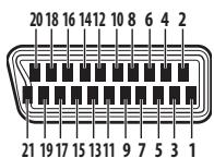
| Pin | DVD & STB | VIDEO | DVR/TV |
| 1 | N.C. | Audio right output | Audio right output |
| 2 | Audio right input | Audio right input | Audio right input |
| 3 | N.C. | Audio left output | Audio left output |
| 4 | Common GND for audio | Common GND for audio | Common GND for audio |
| 5 | GND for (7) | GND for (7) | GND for (7) |
| 6 | Audio left input | Audio left input | Audio left input |
| 7 | Blue input | Blue input | Blue output |
| 8 | Status & aspect input | Status & aspect input | Status & aspect output |
| 9 | GND for (11) | GND for (11) | GND for (11) |
| 10 | N.C. | i/o-Link.A control | i/o-Link.A control |
| 11 | Green input | Green input | Green output |
| 12 | N.C. | N.C. | N.C. |
| 13 | GND for (15) | GND for (15) | GND (15) |
| 14 | GND for (16) | GND for (16) | GND for (16) |
| 15 | Red/S-video(C) input | Red/S-video(C) input | Red/S-video(C) output |
| 16 | Blanking input | Blanking input | Blanking output |
| 17 | GND | GND for (19) | GND for (19) |
| 18 | GND for (20) | GND for (20) | GND for (20) |
| 19 | N.C. | Video output | Video/S-video(Y) output |
| 20 | Video/S-video(Y) input | Video/S-video(Y) input | Video input |
| 21 | GND (plug shield) | GND (plug shield) | GND (plug shield) |

Note
- Specifications and the design are subject to possible modifications without notice, due to improvements.
Published by Pioneer Corporation.
Copyright © 2004 Pioneer Corporation.
All rights reserved.
IMPORTANT

Radio Data System (RDS) 32
Enhanced Other Network (EON). 34
1 Prise PHONES/SETUP MIC
| Écran | Avant | Centre | Sur. | Sur. Arr | Sub W. |
| 2.0ch | ● | | | | |
| 2.1ch* | ● | | | | ● |
| 3.0ch | ● | ● | | | |
| 3.1ch* | ● | ● | | | ● |
| 4.0ch | ● | | ● | | |
| 4.1ch* | ● | | ● | | ● |
| 5.0ch | ● | ● | ● | | |
| 5.1ch* | ● | ● | ● | | ● |
| 6.0ch | ● | ● | ● | ● | |
| 6.1ch* | ● | ● | ● | ● | ● |