Elevate Adjusta 60 - Office Ergotron - Free user manual and instructions
Find the device manual for free Elevate Adjusta 60 Ergotron in PDF.

| Product Type | Height-Adjustable Standing Desk |
| Brand | Ergotron |
| Model | Elevate Adjusta 60 |
| Width | 60 inches (152.4 cm) |
| Depth | 30 inches (76.2 cm) |
| Height Range | 25 to 51 inches (63.5 to 129.5 cm) |
| Weight Capacity | 350 lbs (159 kg) |
| Motor Type | Dual Electric Motors |
| Speed | 1.5 inches per second (3.8 cm/s) |
| Noise Level | < 50 dB |
| Memory Presets | 4 programmable positions |
| Control Panel | Digital keypad with LED display |
| Cable Management | Built-in cable tray and grommets |
| Frame Material | Steel |
| Desktop Material | Laminate or wood (depending on variant) |
| Color Options | White, black, gray |
| Power Supply | AC 100-240V, 50/60Hz |
| Power Consumption | Standby: < 1W, Active: 150W |
| Anti-Collision | Yes, reverse on obstacle detection |
| Warranty | 10 years on frame, 3 years on electronics |
| Weight | Approximately 100 lbs (45 kg) |
| Assembly Required | Yes, tools included |
| Spare Parts | Available from Ergotron or authorized dealers |
| Cleaning | Wipe with damp cloth, avoid harsh chemicals |
Frequently Asked Questions - Elevate Adjusta 60 Ergotron
User questions about Elevate Adjusta 60 Ergotron
0 question about this device. Answer the ones you know or ask your own.
Ask a new question about this device
Download the instructions for your Office in PDF format for free! Find your manual Elevate Adjusta 60 - Ergotron and take your electronic device back in hand. On this page are published all the documents necessary for the use of your device. Elevate Adjusta 60 by Ergotron.
USER MANUAL Elevate Adjusta 60 Ergotron
ASSEMBLY INSTRUCTIONS
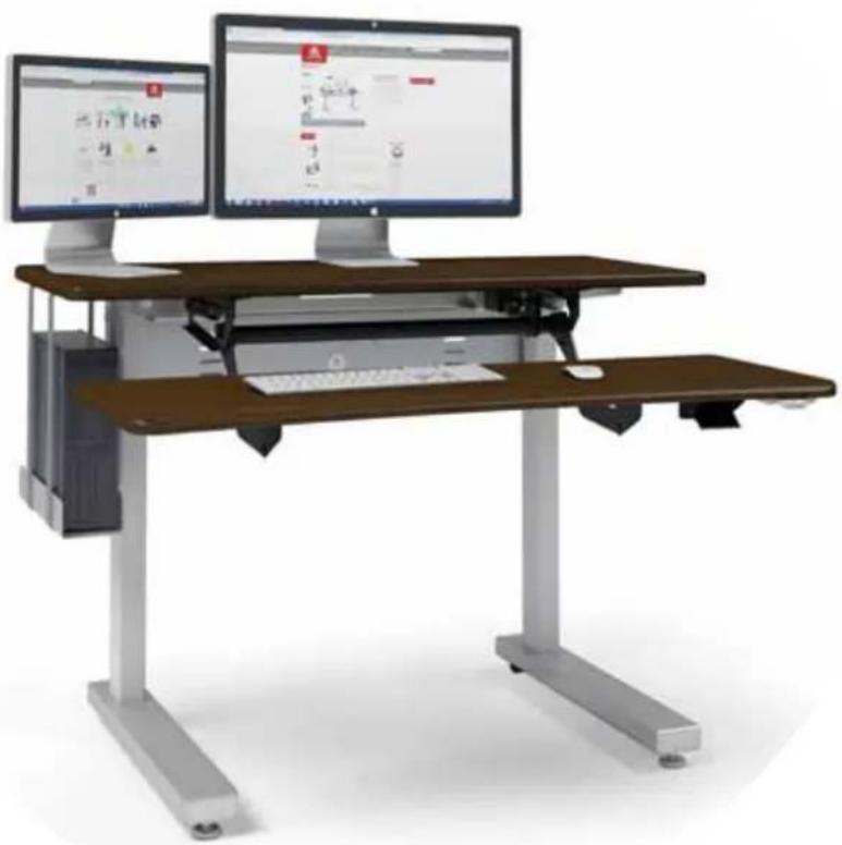
Elevate™ II Adjusta
Dual-surface Table
natural_image
Modern office workstation with two monitors and a wooden workbench, no visible text or symbols on the equipment.Part # Product
MVJB48zz-xx ELT 2 Adjusta 48w
MVJB60zz-xx ELT 2 Adjusta 60w
www.ergotron.com
USA 1-800-325-3841
IMPORTANT SAFETY INSTRUCTIONS
When using an electrical furnishing, basic precautions should always be followed, including the following. Read all instructions before using Elevate II Adjusta.
DANGER
To reduce the risk of electric shock, always unplug this furnishing from the electrical outlet before cleaning.
WARNING
To reduce the risk of burns, fi re, electric shock, or injury to persons:
- Unplug from outlet before putting on or taking of parts.
- Close supervision is necessary when this furnishing is used by or near children, invalids, or disabled persons.
- Use this furnishing only for its intended use as a described in these instructions. Do not use attachments not recommended by the manufacturer.
- Never operate this furnishing if it has a damaged cord or plug, if it is not working properly, if it has been dropped or damaged, or dropped into water. Any damage to the electrical system must be examined & repaired by a qualified electrician.
- Keep the cord away from heated surfaces.
- Do not use outdoors.
- Do not operate where aerosol (spray) products are being used or where oxygen is being administered.
- To disconnect, remove plug from outlet.
- The control box and legs have no user-serviceable parts and must be replaced by components from Ergotron.
- Power cord moves up and down with the table. Make sure power cord moves freely through all positions of the desk.
- Protect the power cord from damage when moving the desk.
- Maximum load is 150 lbs.
SAVE THESE INSTRUCTIONS
CONSIGNES DE SÉCURITÉ IMPORTANTES
WELCOME
Thank you for purchasing Ergotron's Elevate II Adjusta electric lift table!
If you have any questions or if we can help you in any way, please contact us at 800.325.3841.
TOOLS
Your Elevate II comes with these tools:
• 5/32" hex Anthro driver
- 5/32" hex driver bit
- 5mm hex key
• 1/8" hex key
• 3-way wrench
To make the assembly even easier, use your own 3/8" socket for Step 4.
HARDWARE LIST
Product Quantity
| 16 | 1/2" Button-head Screw 7 325-5193-00 |
| 17 | Nylock Nut 7 325-5186-00 |
| 18 | M6-20 Cap Screw 8 325-5272-00 |
| 19 | 3/4" Phillips Screw 4 325-5370-00 |
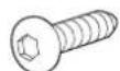
| 20 | 3/4" Button-head Screw 56 325-5575-00 |
| 21 | M6x14 Flat-head Screw 4 325-5435-00 |
| 22 | M6-10 Button-head Screw 8 325-5503-00 |
| 23 | Wire Mgmt Snap-in Clip 2 175-5188-00 |
PARTS LIST
Before beginning assembly of your Elevate II Adjusta, please review the parts list to verify that your
shipment is complete.
| Product | Quantity | |
| 01 | Monitor Surface | 1 |
| 48w | 101-1112-03-00 | |
| 60w | 101-1110-03-00 | |
| 02 | Keyboard Surface | 1 |
| 48w | 101-1113-03-00 | |
| 60w | 101-1111-03-00 | |
| 03 | Gusset X | 1 225-4611-00 |
| 04 | Gusset Y | 1 225-4612-00 |
| 05 | Electric Leg | 2 913-892-00 |
| 06 | Motor Housing | 2 225-4613-00 |
| 07 | Cross Pan | 1 |
| 48w | 225-4619-00 | |
| 60w | 225-4615-00 | |
| 08 | Cable Tray | 1 |
| 48w | 225-4638-00 | |
| 60w | 225-4637-00 | |
| 09 | Control Box (not shown) | 1 400-5506-00 |
| Part | Number | |
| 10 | Control Box Cord (not shown) | 2 400-5182-00 |
| 11 | Power Cord (not shown) | 1 400-5181-00 |
| 12 | Key Pad | 1 400-5357-00 |
| 13 | Key Pad Slider | 1 400-5358-00 |
| 14 | Foot | 2 835-5581-00 |
| 15 | Adjusta Mechanism for 48w Table | 1 225-5546-00 |
| for 60w Table | 575-5072-00 | |
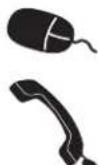
STEP 1 - ATTACH GUSSETS TO TOP
Lay the top surface upside down on a cushioned, non-marring surface. Locate the front edge of the table. On Plus tables, the front of the table has a sloping waterfall edge. On the Basic tables, the back edge of the table has the seam where the edgebanding meets.
Align the Leg Gussets with the holes on the top so the upright fl ange faces the outside of the table and the tapering end points to the front of the table.
Attach each gusset to the top with six 3/4" MDF Screws using the Anthro driver.
natural_image
Technical diagram of a structural component labeled 'Front' with two vertical supports and directional arrows (no text or symbols beyond label)
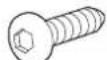
3/4" Button Hd PB Screw
325-5575-00
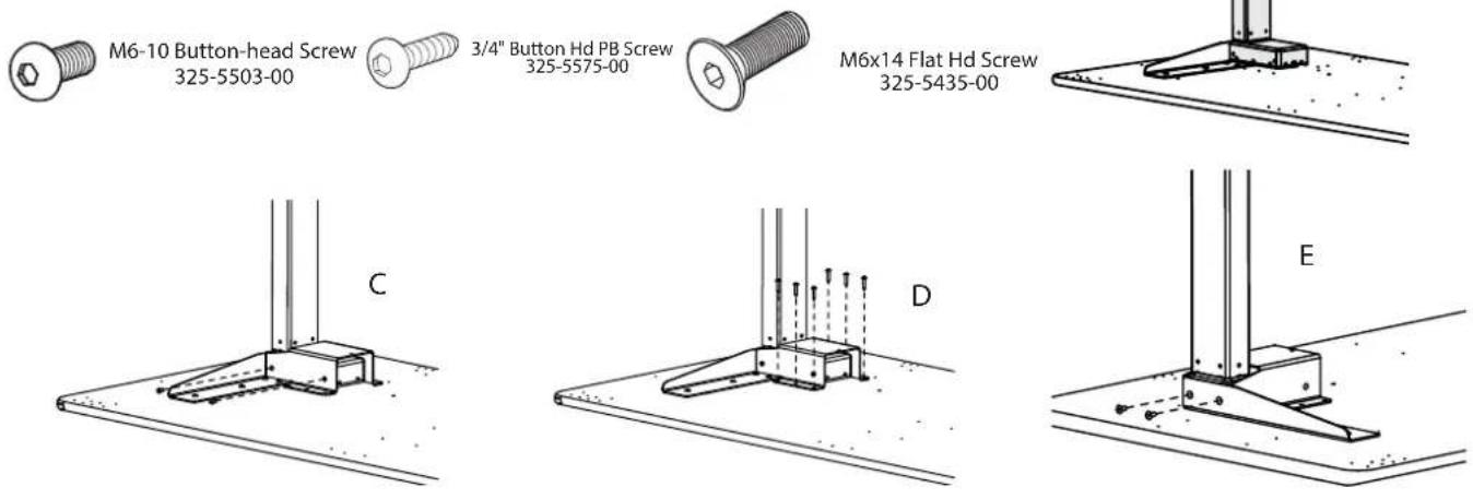
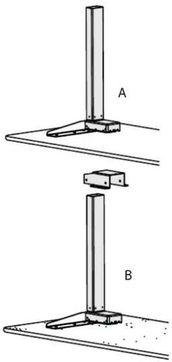
STEP 2 - INSTALL LEGS
■ Align one Leg with one Leg Gusset plug faces the center of the table. The Leg will rest on top of the Gusset's button-head screws, so it may feel a little wobbly. [A]
■ Slide a Leg Housing over the Leg and down until it covers the Leg Motor and the six screw holes on the housing line up with the six pre-drilled holes on the shelf. [B]
■ Move to the front of the table and attach the front of the Housing to the Leg with two M6-10MM Button Hd Screws (325-5503-00) using the Anthro driver. Tilt the leg slightly to align the holes. [C]
■ Loosely attach the Housing to the shelf with six 3/4" Button Hd PB Screws (325-5575-00). [D]
■ Attach the side of the Leg to the Leg Gusset with two M6-14 Flathead Screws (325-5435-00). [E]
■ Repeat for the other Leg and Housing.
natural_image
Technical diagram showing two mechanical assembly steps labeled A and B, with no visible text or symbols.STEP 3 - INSTALL THE CROSS PAN
Align the Cross Pan with the Leg Assemblies so the pair of fl anges on the pan line up with the pre-drilled holes on the table. Attach the back of the pan to the top with four 3/4" MDF Screws (325-5575-00) and attach the front of the pan to the top with three 3/4" MDF Screws.
Attach the pan to each leg housing with two M6x10 Button-head Screw (325-5503-00) using the Anthro driver.
Tighten all fasteners.
3/4" Button Hd PB Screw
325-5575-00

M6-10 Button-head Screw
325-5503-00
natural_image
Technical line drawing of a mechanical assembly with two vertical posts and a base plate, showing structural details (no text or symbols)Step 4 - INSTALL CONTROL BOX
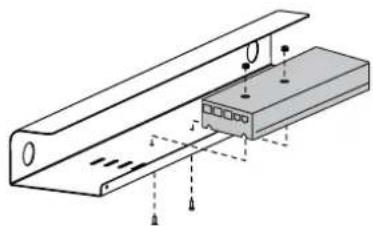
Align the Control Box with the Cable Tray so the holes on the Control Box line up with the holes on the Cable Tray. The Control Box installs at the center of the tray on the 48w table. The 60w table comes with three installation points (left, center, and right). Attach the box to the tray with two 1/2" Button-head Screws and two Nylock Nuts using your own 3/8" socket (or the 3-way wrench provided) and the smallest hex key (1/8") in your kit.
natural_image
Technical diagram of a mechanical assembly with no visible text or symbolsAttaching the Control Box to the Cable Tray of a shallow 48" wide table.

1/2"Button-hd Screw 325-5193-00

Nylock Nuts
325-5186-00
Step 5 - INSTALL CABLE TRAY
- Align the Cable Tray with the back of the table so the holes on the threaded posts on the cross pan line up with the holes on the cable tray. Attach the tray to the pan with three Nylock Nuts using your own 3/8" socket or the 3-way wrench provided. (The plastic end of the nut faces up.)
■ Connect a 1-meter Control Box Cable to each leg cable, then plug each into a port on the Control Box through the opening in the support pan. Feed extra cable length through an opening in the support pan so it's organized in the Cable Tray.
Plug the Power Cord into the Control Box.
Use the provided cable clips to route and organize cords. Install one cable clip next to the Leg Gusset for the Keypad Cord (Installed in Step 8). Install the other clip next to the Cross Pan for the Control Box Cables.

1/2" Flat-head Screw
325-5193-00

Nylock Nuts
325-5186-00
natural_image
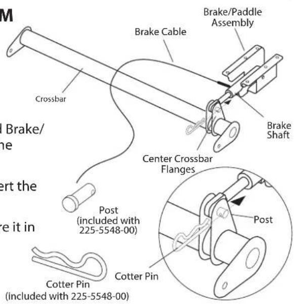
Technical line drawing of a mechanical assembly with no visible text or symbolsSTEP 6A - ASSEMBLE ADJUSTA MECHANISM
Your Adjusta mechanism comes unassembled and is boxed separately inside the package. Locate the small bag of hardware included with the Adjusta Mechanism. It includes (1) Post, (1) Cotter Pin, (2) Hex Nuts, (2) Wood Screws, and (2) Cable Mounts.
Begin to assemble the mechanism by first locating the Crossbar and Brake/Paddle assembly and position them as shown at right. Depress the Paddle once to free the Brake Shaft.
Place the Brake Shaft between the two center Crossbar fl anges. Insert the Post through both center Crossbar fl anges and the Brake Shaft.
Install the Cotter Pin through the single opening of the post to secure it in place.
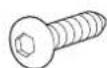
3/4" Button Hd PB Screw
325-5575-00
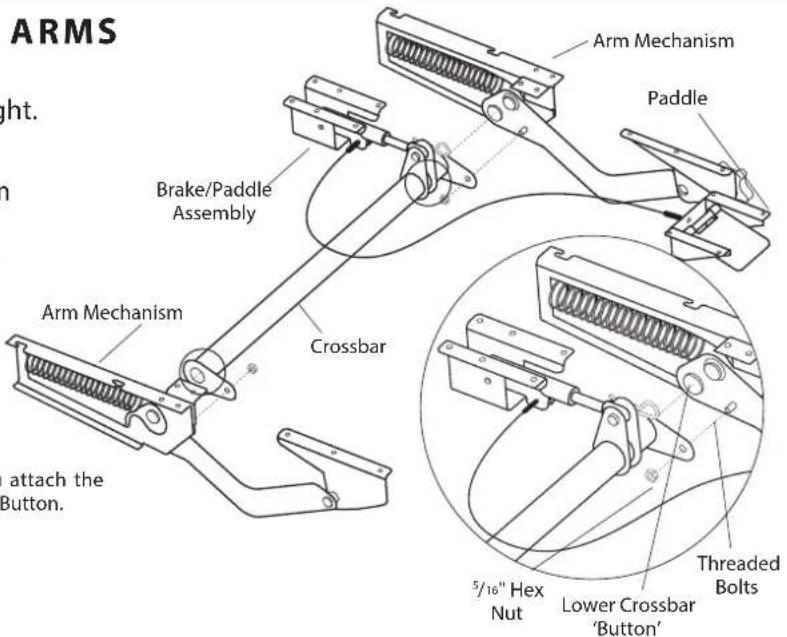
STEP 6B - ASSEMBLE ADJUSTA ARMS
Unpack the remaining Adjusta mechanism components and arrange them as shown at right.
Place one Crossbar End onto the lower Crossbar Button and Threaded Bolt located on each Arm Mechanism. Secure the Crossbar to the Arm Mechanism using one 5/16" Hex Nut onto the Threaded Bolt.
Repeat for remaining Crossbar End and Arm Mechanism.
NOTE: it is very important that you attach the Crossbar ONLY to the Lower Crossbar Button.
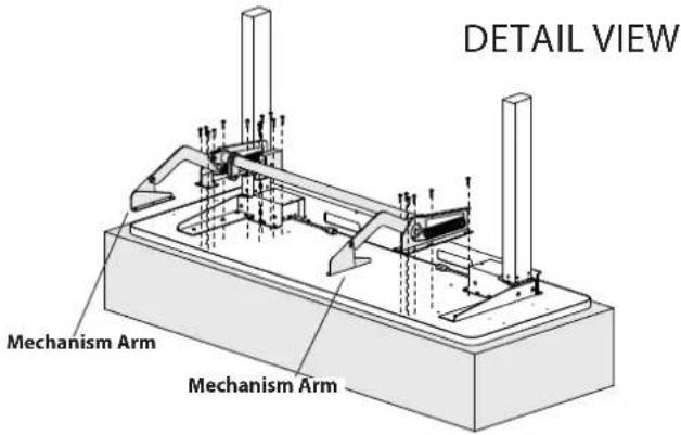
STEP 7 - ATTACH ADJUSTA MECHANISM TO MONITOR SURFACE
Loosely attach the second Mechanism Arm to the Monitor Surface using a total of six 3/4" Button-head Screws.
Align the brake assembly with the six holes on the Monitor Surface. It may be necessary to depress the paddle in order to position the brake.
Secure the brake assembly with six 3/4" Button-head Screws.
3/4" Button Hd PB Screw 325-5575-00
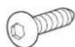
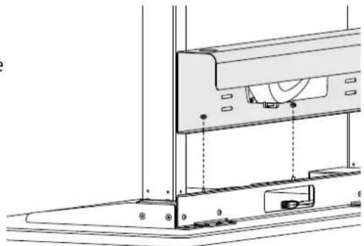
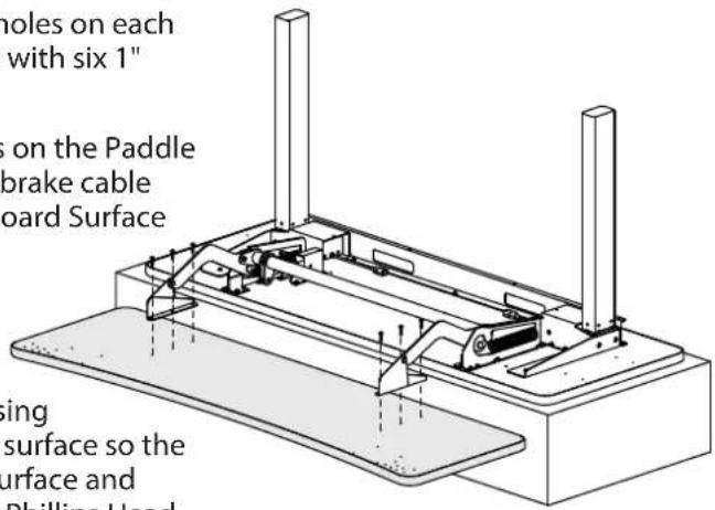
STEP 8 - ATTACH ADJUSTA MECHANISM TO KEYBOARD SURFACE
Slide the Keyboard Surface under the mechanism arms. Align the three holes on each end of the Keyboard surface with the three holes on each mechanism arm. Secure the arms to the Keyboard Surface with six 1" Button-head Screws.
Position the Paddle on the Keyboard Surface so the four holes on the Paddle align with the four holes on the Keyboard Surface and the brake cable runs under the Adjusta Bar. Secure the Paddle to the Keyboard Surface with four 3/4" Button-head Screws.
The keypad can be installed on the left or the right. Choose a location, just remember that the table's upside down now, so when you flip the table over, the keypad will be on the opposite side. Align the keypad and its housing with the four pre-drilled holes at the front of the keyboard surface so the buttons are face-down at the front edge of the keyboard surface and the flat side of the housing is against the shelf. Using four Phillips Head Screws, attach the keypad and its housing to the front of the worksurface.
Route the Keypad's cable back to the Cross Pan and plug it into the Control Box. Feed extra cable length through an opening in the support pan so it's organized in the Cable Tray.
3/4" Button Hd PB Screw 325-5575-00

3/4" Phillips Screw 325-5370-00
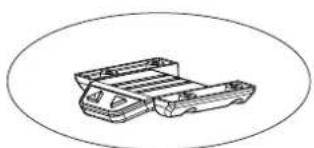
natural_image
Technical line drawing of a mechanical component with two parts stacked, enclosed in an oval frame (no text or symbols)Keypad and Slider 888-24-356-G-00 rev. B • 01/17
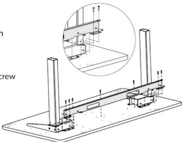
Step 9 - INSTALL FEET
Align one foot with each leg so the wheels are at the back. Attach the foot to the leg with four M6x20 Socket-head Screws using the Anthro driver. Repeat for the other foot.
With the help of another person, carefully rotate the table onto its feet.
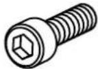
M6-20 Cap Screw 325-5272-00
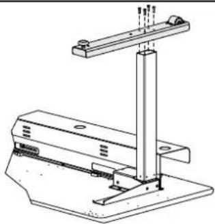
natural_image
Technical line drawing of a mechanical support structure with mounting base and vertical rod (no text or symbols)CONGRATULATIONS! YOUR ELEVATE II ADJUSTA ASSEMBLY IS COMPLETE!
RATINGS
Electrical Rating
■ Voltage rating: 120Vac, 60 Hz. When desk is moving with rated load: 400W. When desk is not moving: less than 100mW.
Temperature Ratings
- Ambient temperature: 41 degrees F to 140 degrees F. Storage temperature: -4 degrees F to 158 degrees F. - Acclimate table to ambient temperature before use.
Load Rating
■ Elevate II Adjusta has a weight capacity of 150 lbs of distributed load on the back monitor surface and 40 lbs of distributed load on the front keyboard surface.
Duty Cycle
■ Elevate II Adjusta has a 10% duty cycle. This provides 6 minutes of movement per hour or two minutes of continuous use at full load. Once the table reaches its duty cycle, the table shuts down to cool; this usually takes about 20 minutes. Duty cycle is reduced when the load exceeds approved weight limit or temperature is outside the stated range.
SAFETY CHECK
- Plug in the table and home the legs. To home the legs, move the table to its lowest position, release the DOWN button, then press and hold the DOWN button for 5 seconds. The table will bump a few times, then rest.
- Raise the table to its highest position. Watch all the cords and cables as the table moves to verify that cords aren't wrapped around anything and that nothing interferes with the movement of the table.
■ Every time you add equipment onto the table, route cords into the cable tray. Carefully move the table through its entire range of motion to be sure that your power and data cables are long enough. Check the area around your table for obstructions below, beside, and above the table to be sure there are no collisions.
■ Verify that the load is distributed evenly across the table.
MOVING THE TABLE
- Keep your equipment safe: remove equipment from the table before you move it.
■ Before moving the table, lower the table all the way down and raise the keyboard surface all the way up.
■ To move the table, lift the front keyboard surface enough to get the front feet off the ground, and roll it into place.
■ Lift (don't roll) the table over thresholds, transitions, or bumps.
TROUBLESHOOTING GUIDE
Is the table giving you trouble? Try these steps first. Still need help? Contact Ergotron at 800.325.3841.
Table won't go up, but it will go down.
- Inspect the leg cables, control box cable, and power cable to be sure they are connected properly and not damaged. Need replacements? Contact Ergotron at 800.325.3841.
■ Lower the table to its lowest position, release the button, the press the DOWN button again for 5 seconds to home the legs. The table will bump a few times, then rest.
Table won't move at all: no up, no down.
- Has the table exceeded its duty cycle, moving more than 6 minutes per hour or 2 minutes continuously? If so, rest the table for 20 minutes and try again.
- Inspect the leg cables, control box cable, and power cable to be sure they are connected properly and not damaged.
■ Test the cables:
- Unplug the Leg Cable that is plugged into Port 1 of the control box.
- Push the DOWN button for 3 seconds and then the UP button for 3 seconds.
- Unplug the Power Cord from the Control Box.
- Plug the Leg Cable back into Port 1.
- Plug the Power Cord back into the Control Box.
- Push the DOWN button and hold until the table reaches its lowest position and stops, then release.
- Push the DOWN button again and hold for 5 seconds.
- Push the UP button to verify the that the table goes up.
Desk will only go up a few inches...then stop...then up another few inches...then stop again.
■ Verify that the load on the table does not exceed its 150 lbs lift capacity.
Cleaning instructions? Clean the table with a mild detergent and a soft cloth.
For Warranty visit: www.ergotron.com/warranty
For Service visit: www.ergotron.com
For local customer care phone numbers visit: http://contact.ergotron.com
Americas Sales and Corporate Headquarters
1181 Trapp Rd.
St. Paul, MN USA
1-800-325-3841
www.ergotron.com
sales@ergotron.com
ERGOTRON®

While Ergotron, Inc. makes every effort to provide accurate and complete information on the installation and use of its products, it will not be held liable for any editorial errors or omissions (including those made in the process of translation from English to another language), or for incidental, special or consequential damages of any nature resulting from furnishing this instruction and performance of equipment in connection with this Instruction. Ergotron, Inc. reserves the right to make changes in the product design and/or product documentation without notification to its users. For the most current product information, or to know if this document is available in languages other than those herein, please contact Ergotron. No part of this publication may be reproduced, stored in a retrieval system, or transmitted in any form or by any means, electronic, mechanical, photocopying, recording or otherwise without the prior written consent of Ergotron, Inc., 1181 Trapp Road, Eagan, Minnesota, S5121, USA Patents Pending and Patented U.S. & Foreign. Ergotron is a registered trademark of Ergotron, Inc.