
Zip40 - Hand truck Ergotron - Free user manual and instructions
Find the device manual for free Zip40 Ergotron in PDF.


| Product Type | Monitor Arm |
| Brand | Ergotron |
| Model | Zip40 |
| Maximum Screen Size | 40 inches |
| Weight Capacity | 33 lbs (15 kg) |
| Mounting Standard | VESA 75x75 or 100x100 |
| Arm Type | Articulating with gas spring |
| Material | Aluminum and steel |
| Color | Black |
| Height Adjustment Range | 14 inches (35.6 cm) |
| Tilt Range | -5° to +75° |
| Rotation | 360° |
| Installation | Clamp or grommet mount |
| Cable Management | Integrated clips |
| Cleaning Instructions | Wipe with damp cloth, no solvents |
| Safety | Exceeds BIFMA standards |
| Spare Parts Availability | Contact Ergotron support |
| Warranty | 10 years |
| Certifications | TUV, UL listed |
Frequently Asked Questions - Zip40 Ergotron
User questions about Zip40 Ergotron
0 question about this device. Answer the ones you know or ask your own.
Ask a new question about this device
Download the instructions for your Hand truck in PDF format for free! Find your manual Zip40 - Ergotron and take your electronic device back in hand. On this page are published all the documents necessary for the use of your device. Zip40 by Ergotron.
USER MANUAL Zip40 Ergotron
Zip40 Charging & Management Cart
Includes PowerShuttle™ Technology
natural_image
Illustration of a multi-level industrial machine with battery packs on wheels, showing internal compartments and a hand inserting a cable (no text or symbols)Components


Tools Needed

natural_image
Illustration of three different tools: a toolbox, a screwdriver with a plus sign, and a sawtooth tool with 8mm diameter (no text or symbols on the tools themselves)For the latest User Installation Guide please visit: www.ergotron.com

User's Guide - English
Hazard Symbols Review
These symbols alert users of a safety condition that demands attention. All users should be able to recognize and understand the signifi cance of the following Safety Hazards if encountered on the product or within the documentation. Children who are not able to recognize and respond appropriately to Safety Alerts should not use this product without adult supervision!
| Symbol | Signal Word | Level of Hazard |
 | NOTE | A NOTE indicates important information that helps you make better use of this product. |
 | CAUTION | A CAUTION indicates either potential damage to hardware or loss of data and tells you how to avoid the problem. |
 | WARNING | A WARNING indicates either potential for property damage, personal injury, or death. |
 | ELECTRICAL | An Electrical indicates an impending electrical hazard which, if not avoided, may result in personal injury, fire and/or death. |
Safety

Warning: Unplug power cable from outlet and make sure power button is turned off before removing side cover. Removing side cover with power on may cause equipment damage and/or serious personal injury.

WARNING
MOVING PARTS CAN CRUSH AND CUT
Unplug power cord. DO NOT place hands on or near fans. Placing hands on or near fans may cause equipment damage and/or serious personal injury.


WARNING: MOVING PARTS CAN CRUSH AND CUT. Unplug power cord. DO NOT place hands on or near fans. Placing hands on or near fans may cause equipment damage and/or serious personal injury.
Features & Specifications


A + B + C + D + E ≤ 255 lbs. (116 kg)
CAUTION: DO NOT EXCEED MAXIMUM LISTED WEIGHT CAPACITY. SERIOUS INJURY OR PROPERTY DAMAGE MAY OCCUR!
1
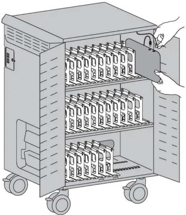
Open doors.

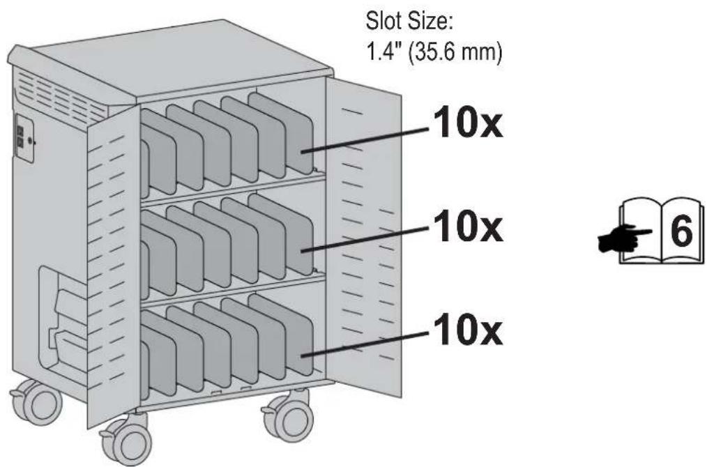
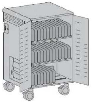
2 Choose configuration for number of devices.
40x Cart is already configured for this, please skip to page 9.

30x Dividers and Ethernet cables will need to be reconfi gured for this set up, please see instructions on pages 6-8.
30x

natural_image
Illustration of a multi-tiered industrial machine with wheels and open doors (no text or symbols)
Unplug power cable from cart and remove side cover.
WARNING
MOVING PARTS CAN CRUSH AND CUT
Unplug power cord. DO NOT place hands on or near fans Placing hands on or near fans may cause equipment damage and/or serious personal injury.


WARNING: MOVING PARTS CAN CRUSH AND CUT. Unplug power cord. DO NOT place hands on or near fans. Placing hands on or near fans may cause equipment damage and/or serious personal injury.


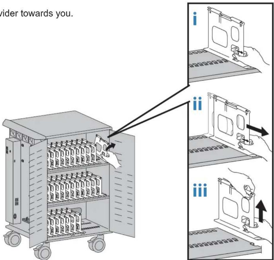
To configure for 30 devices, remove dividers.
i. Pull lever towards you.
ii. With lever pulled, slide divider towards you.
iii. Lift up and off.

natural_image
Illustration of a multi-tiered industrial machine with wheels and open doors, labeled '30x' (no text or symbols on the device itself)C
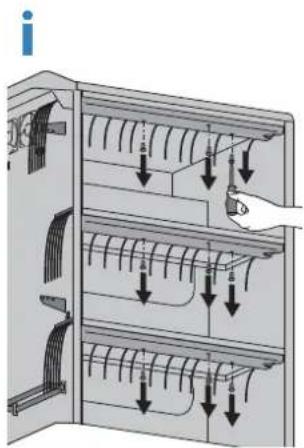
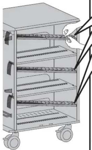
To configure for 30 devices, reroute cables.
i. Remove cable tray 3x screws.
ii. Press tab to release clip and lower cable tray.


To configure for 30 devices, reroute cables.
i. Remove cable clips.
ii. Remove Ethernet cables in rows 2, 5, 8, 11, 14 and keep or route cables in rows 1^ , 3^ , 4^ , 6^ , 7^ , 9^ , 10^ , 12^ , 13^ , 15^ .
iii. Reattach cable clips.
natural_image
Illustration of a multi-level kitchen or storage unit with shelves and a hand inserting wires (no text or symbols visible)
30x

natural_image
Illustration of a multi-level industrial machine with wheels and internal compartments (no text or symbols)
Reattach cable trays.

natural_image
Diagram of an open electrical cabinet with internal components and a hand inserting a component (no text or symbols present)ii

natural_image
Diagram of an open electrical control cabinet with internal wiring and directional arrows indicating flow or movement (no text or symbols present)
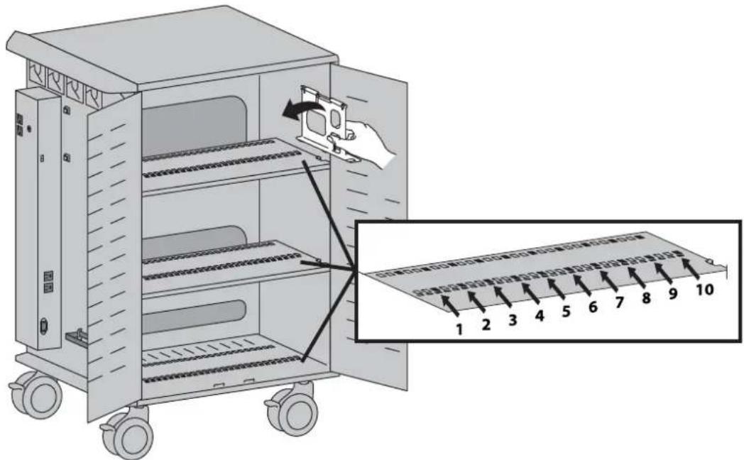
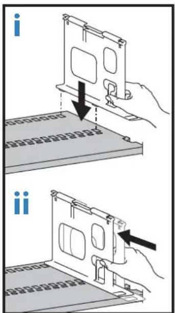
To configure for 30 devices, reattach dividers, 10 per shelf.
i. Insert tabs on bottom of divider into designated holes on shelf.
ii. Slide divider away from you to lock into place.
40x
natural_image
Illustration of a multi-tiered industrial machine with wheels and open door (no text or symbols)30x

natural_image
Illustration of a multi-tiered industrial machine with wheels and open doors (no text or symbols)3 Attach spacers if your devices are ≤ 9" (229 mm).
40x
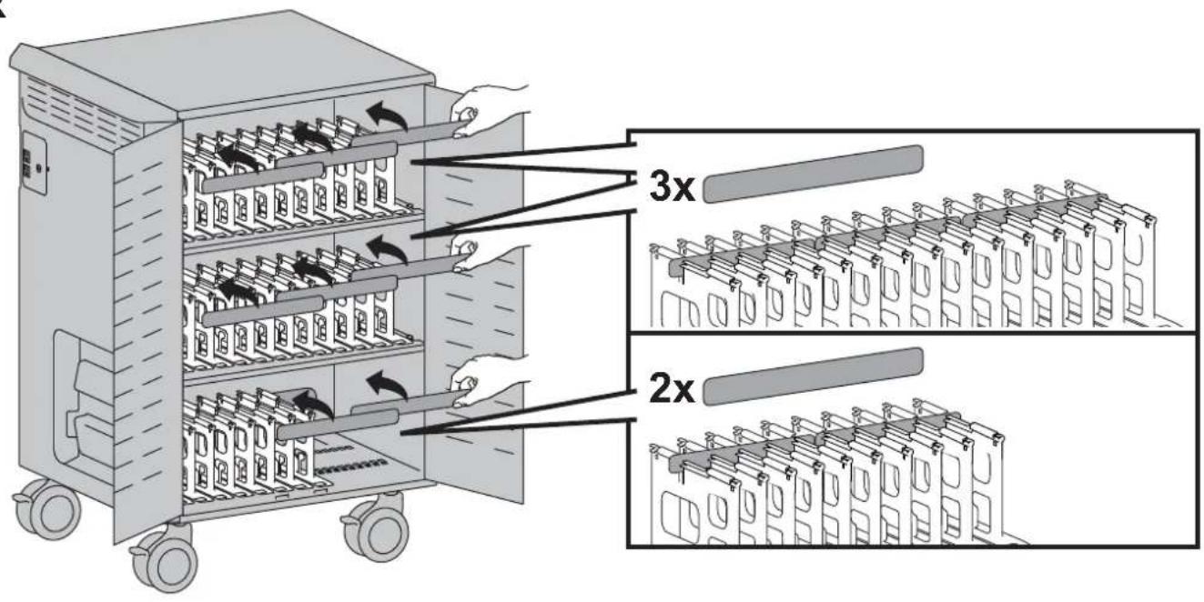
30x

4 Remove back panel.

natural_image
Illustration of a portable industrial machine with wheels and a handle, no text or symbols present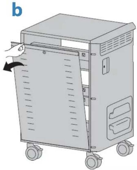
natural_image
Illustration of a mechanical device with wheels and a door, showing internal compartments and a hand inserting a cable (no text or symbols)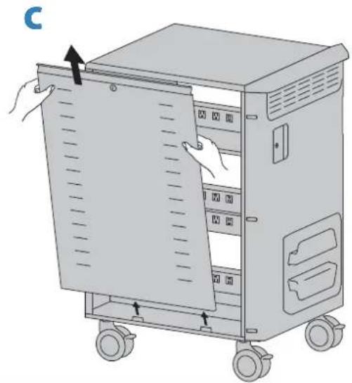
natural_image
Illustration of a server rack with hand inserting a drive into the cabinet (no text or symbols visible)5 Plug in and route power cables.
There are different instructions for each type of power cable. Follow the instructions that match your style power cable.

a. Plug in the power cables for the top shelf. Use the top row of outlets, and for the 40 device configuration, every other outlet on the second row. Store the power cables in the top basket.
b. Route the device plugs between the basket and the top outlet row and up through the top of the dividers. Make sure there is enough slack in cable to plug into device.
c. Bundle cables and store in top basket.
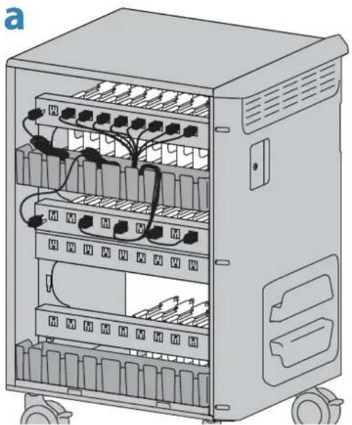
natural_image
Illustration of an open industrial electrical control cabinet with multiple rows of switches and wiring (no text or labels visible)10 of 19

natural_image
Diagram of an electrical enclosure with internal components and wiring, showing a close-up of the enclosure's internal structure (no text or symbols present)888-24-324-G-02 rev. E·08/18

d. Plug in the power cables for the Middle shelf. Use the entire third outlet row, and for the 40 device configuration, the remaining outlets on the second row. Store the power cables from the second outlet row in the top basket and the power cables from the third row in the bottom basket.
e. Route the device plugs under the third outlet row and up through the top of the dividers. Make sure there is enough slack in cable to plug into device.
f. Bundle cables and store in the baskets.
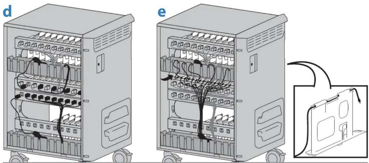
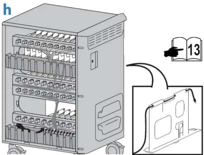
g. Plug in the power cables for the bottom shelf. Use the bottom row of outlets. Store the power cables in the bottom basket.
h. Route the device plugs between the basket and the bottom outlet row and up through the top of the dividers. Make sure there is enough slack in cable to plug into device.
i. Bundle cables and store in bottom basket.

natural_image
Illustration of an electrical control cabinet with multiple battery modules and wiring (no text or symbols visible)888-24-324-G-02 rev. E·08/18
11 of 19
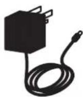
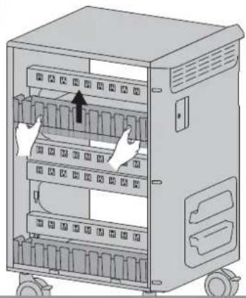
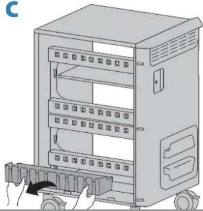
Remove the baskets designed to hold the power supplies that are not present with this type of power cable.
a. Lift basket up to unlock tab.
b. Pull basket out.
c. Lift bottom basket up to unlock tab then pull out.
a
natural_image
Illustration of an open industrial control cabinet with multiple rows and a directional arrow indicating movement (no text or symbols present)b

natural_image
Illustration of an electrical cabinet with multiple panels and a hand inserting a component (no text or symbols visible)C
natural_image
Illustration of a server rack with multiple panels and a hand inserting a component (no text or symbols visible)d. Plug in the power cables for the top shelf. Use the top row of outlets, and for the 40 device configuration, every other outlet on the second row. Route the device plugs under the top outlet row and up through the top of the dividers. Make sure there is enough slack in cable to plug into device.
e. Plug in the power cables for the Middle shelf. Use the third row, and for the 40 device configuration, the remaining outlets on the second row. Route the device plugs under the third outlet row and up through the top of the dividers. Make sure there is enough slack in cable to plug into device.
f. Plug in the power cables for the bottom shelf. Use the bottom row of outlets. Route the device plugs under the bottom outlet row and up through the top of the dividers. Make sure there is enough slack in cable to plug into device.
d

natural_image
Illustration of an electrical control cabinet with multiple switches and wiring (no text or symbols visible)
natural_image
Illustration of an electrical control cabinet with multiple modules and wiring (no text or symbols visible)f

natural_image
Illustration of an electrical enclosure with multiple compartments and wiring (no text or symbols)
natural_image
Illustration of a train carriage with hands holding a door panel, showing internal compartments and wheels (no text or symbols)
natural_image
Illustration of a portable kitchen unit with wheels and a hand inserting a paper into the door (no text or symbols)
natural_image
Illustration of a portable industrial machine with wheels and a handle, no text or symbols presentOptional Wireless Access Point (WAP) and Switch installation (not included).
7
Unplug power cable from cart and remove side cover.

WARNING: MOVING PARTS CAN CRUSH AND CUT. Unplug power cord. DO NOT place hands on or near fans. Placing hands on or near fans may cause equipment damage and/or serious personal injury.

8
Attach WAP with velcro strap. Plug WAP into Auxiliary outlet.

natural_image
Illustration of a train or electrical cabinet with hands operating it, showing internal components and wiring (no text or symbols)Access door to unplug WAP.

natural_image
Illustration of a device being inserted into a rack, showing internal components and a close-up view of the component (no text or symbols present)9
Ethernet switch attachment:
a. Attach unit to cart.
b. Plug in external Ethernet cable and WAP Ethernet cable to switch.
c. Plug in Ethernet cables from devices.
d. Store excess cables between switch and cart.
e. Follow manufacturers instructions for WAP and Switch set up.
4x

M5 x 10mm
4x


8mmM5
a

natural_image
Illustration of a server rack with hands connecting to a central panel and cable, no text or symbols presentb

natural_image
Diagram of an electronic device with a central panel and attached cables, showing no text or symbols.C

natural_image
Illustration of an electronic device with a hand connecting cables to a panel, no text or symbols visibled

natural_image
Illustration of an electrical enclosure with a hand inserting wires into the panel (no text or symbols visible)10
Attach side cover and plug power cable back into cart.
NOTE: Route external Ethernet cable through side cover access door.
a


natural_image
Illustration of a hand inserting cable into a device panel, with a power outlet and electrical outlet visible (no text or symbols)11
Plug in and insert devices.

natural_image
Illustration of a hand inserting a file into a rack-mounted server unit (no text or symbols visible)12
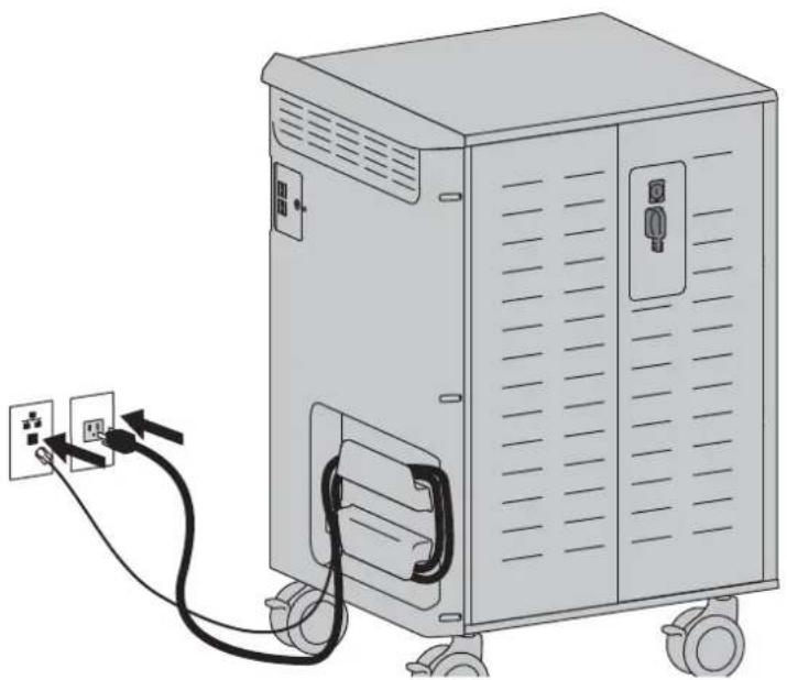
Plug in power and Ethernet cables and turn cart power on.
natural_image
Illustration of a portable electric vehicle with power outlet and cable, no text or symbols present
Cleaning and Maintenance
WARNING: Failure to observe the following safety notices may result in serious personal injury or equipment damage.
Inspect for damage, dirt and debris on a regular basis. All paint and plastic components used in the Cart will withstand cleaning by most commonly used, diluted, non-abrasive solutions such as quaternary ammonia compounds, ammonia enzyme cleaners, bleach, or alcohol solutions. It is recommended that any cleaning solution be tested on a small, inconspicuous area to ensure it does not harm the surface of the Cart.
- Marks from permanent marker, dry-erase marker, and pens can be removed with 91% isopropyl alcohol and a soft cloth.
- lodine stains can be removed with commonly used cleaners and a soft cloth.
- Do not use steel wool or other abrasive materials that may damage the surface finish.
Electrical: To avoid risk of electric shock, do not expose electrical components to water, cleaning solutions or other potentially corrosive liquids or substances.
Electrical: Do not immerse Cart or Cart components in liquid or allow liquids to flow into the Cart. Wipe all cleaners off surface immediately using a damp cloth. Dry the surface thoroughly after cleaning.
Electrical: Do not use flammable cleaners on Cart surfaces.
CAUTION: Adjustment, Service, Replacement - DO NOT attempt to adjust, service or replace any part of the Cart unless directed to do so through Ergotron-approved documentation (i.e. installation instructions). Only Ergotron, Inc. or an Ergotron-certified entity may adjust, service or replace Cart components. If any component on the Cart is missing or damaged, the Cart must not be used. Contact Ergotron immediately to request a replacement part.
CAUTION: Casters - Check casters periodically to make sure they are clean and free of debris that would prevent smooth travel. Avoid moving Cart across uneven, dirty, or damaged surfaces.
CAUTION: Customer Equipment- Make sure equipment is balanced and installed securely to Cart. Contact Ergotron for information about moving Cart components.
Equipment Electrical Safety
There are specific risks associated with the use of equipment having power cables. You must be aware of, and avoid these risks when the Cart is located in close proximity to children.
WARNING: Failure to observe the following Electrical Safety notices can result in fire or death by electric shock.
Electrical cables can be hazardous. Misuse can result in fire or death by electrical shock.
• Double Pole / Neutral Fusing
- Inspect power cables thoroughly before each use.
- Do not use cables that are damaged.
- Insert the plug completely into the outlet.
- Grasp the plug to remove from the outlet.
- Do not unplug by pulling on the cable.
- Do not use excessive force to make connections.
- Do not plug the cable into an extension cable.
- Do not remove, bend or modify any metal prongs or pins of cable.
- Do not drive, drag or place objects over the cable.
- Do not walk on the cable.
- Avoid overheating. Uncoil the cable and do not cover it with any material.
- Do not run cable through doorways, holes in ceilings, walls or floors.
Keep the Cart away from water.
- Do not use it when wet.
- Do not place the Cart in close proximity to flammable liquids or gases.
CAUTION: The power disconnect for this equipment is the AC power cable. Therefore the socket outlet should be easily accessible and should be installed near the equipment.
Safe Use Recommendations
There are specific risks associated with the use of Cart when moving or stationary (for charging or storage). You must be aware of, and avoid these risks when the Cart is located in close proximity to children.
WARNING: Failure to observe the following Cart Use Safety notices may result in serious personal injury or equipment damage.
WARNING: Death or serious injury may occur when children climb on audio and/or video equipment furniture. A remote control or toys placed on the furnishing may encourage a child to climb on the furnishing and as a result the furnishing may tip over on to the child.
WARNING: Relocating audio and/or video equipment to furniture not specifically designed to support audio and/or video equipment may result in death or serious injury due to the furnishing collapsing or over turning onto a child.
Only Adults should move this cart.
- Do not allow anyone to sit, stand, or climb on the Cart.
- Do not lift the Cart from the bottom.
- Do not block the fans and vent openings. To prevent overheating, leave at least 127 mm (5-inch) clearance around fans and vents.
The Cart is designed to be used indoors only.
- Do not use the Cart to transport or store equipment other than what has been noted in this guide.
- Do not use the Cart to store liquids or cleaning supplies.
- Do not place heavy objects on the Cart surface or shelf.
- The maximum weight capacity of the top surface is 11.4 kg (25 lb).
– The maximum weight capacity of the shelf is 34.7 kg (76.5 lb).
- No TV/Monitor is to be used on top of cart.
Moving the Cart
• Before moving the Cart:
-
Disconnect the power cable from the wall.
-
Disconnent Ethernet cable from the wall if present.
-
Make sure the cable is wrapped and secure.
-
Close and lock the doors.
-
Remove items from the top work surface.
-
Unlock the casters.
- Push (do not pull) the Cart for optimum maneuverability and to prevent muscle strain.
- Do not move the Cart across rough, uneven or irregular surfaces such as gravel.
Parking the Cart
Observe these safety alerts for times when the cart is stationary:
- Do not park the Cart in areas of heavy traffic.
- Do not run cables through doorways, holes in ceilings, walls, or floors.
- Do not run cables across hallways, classrooms, or other areas where they will be walked on.
- Do not leave Cart unattended in areas where children have access.
- Keep Cart doors closed and locked whenever it is unattended or parked for charging or storage.
- Keep Cart casters locked whenever it is unattended.

DANGER! Electrical cables can be hazardous.
Misuse can result in fire or death by electrical shock.


Specifications
This device complies with Part 15 of the FCC Rules. Operation is subject to the following two conditions:
1) This device may not cause harmful interference.
2) This device must accept any interference received, including interference that may cause undesired operation.
CAN ICES3(A)/NMB-3(A).
Changes or modifications not expressly approved by the Ergotron could void the user's authority to operate the equipment.
Intended for institutional use.
Cart weight (without equipment)
181 lb (82 kg)
Rated weight capacity
Top Work Surface
25 lb (11.3 kg)
Device Slot Size
17.1"W x 11.2"H (43.4x28.4 cm)
Device with case and power cord installed must fit within these dimensions.
Max Dimensions of WAP
10"W x 10"H x 2.2"D (25.4x25.4x5.6 cm)
Max Dimensions of Switch
(Must meet 1U Rack Mount Standard)
17.5"W x 12.4"H x 1.8"D (44x26x4.4 cm)
Cooling/ventilation
Four 12V DC fans, ventilated doors and side panel
External power outlet(s)
One or two outlets, depending on region
100-120V\~, 4A max, 50/60 Hz or
220-240V\~, 2A max, 50/60 Hz
WAP and Switch Outlets
100/120V\~, 4A max, 50/60 Hz or
220-240V\~, 2A max, 50/60 Hz
Shipping dimensions
37"W x 30"D x 52"H (94x75x132 cm)
Shipping weight
227 lb (103 kg)
Power system
100-120V\~,12A,50/60Hz
Maximum input for 5 devices cannot exceed 8.5A
or
220-240V\~,10A,50/60Hz
Maximum input for 5 devices cannot exceed 4.0A
Environmental
Temperature range:
Operating 0° to 30°C (32° to 86°F)
Storage -40° to 60°C (-40° to 140°F)
Relative humidity (maximum):
Operating 10%–90% (non condensing)
Storage 5%–95% (non condensing)
Altitude (maximum): 2000 m (6,562 ft)
Certification:
UL 60950 Safety of Information Technology Equipment, CAN/CSA C22
2 No. 60950; UL 1678 Household, Commercial, and Institutional-Use
Carts, Stands, and Entertainment Centers for Use with Audio and/or Video Equipment.
ICES-003 Issue 5, Class A
FCC Part 15 Class A
RoHS and REACH compliant material used.
Troubleshooting
| Notification Probable Cause Resolution | |
| Blue ON/OFF switch flashing. There is an over-current condition that cannot be resolved. Power has been removed to the devices. An over-current condition could be a defective device installed or possibly something plugged into external auxiliary outlet causing too much current. | To correct, remove source of over-current condition, then unplug from wall and then plug back in, or push power switch off then back on to reset. |
For Warranty visit: www.ergotron.com/warranty
For Service visit: www.ergotron.com
For local customer care phone numbers visit: http://contact.ergotron.com

NOTE: When contacting customer service, reference the serial number.

natural_image
Illustration of a portable industrial machine with wheels and a labeled component (no text or symbols)ERGOTRON®

PowerShuttle
© 2015 Ergotron, Inc. All rights reserved.
While Ergotron, Inc. makes every effort to provide accurate and complete information on the installation and use of its products, it will not be held liable for any editorial errors or omissions (including those made in the process of translation from English to another language), or for incidental, special or consequential damages of any nature resulting from furnishing this instruction and performance of equipment in connection with this instruction. Ergotron, Inc. reserves the right to make changes in the product design and/or product documentation without notification to its users. For the most current product information, or to know if this document is available in languages other than those herein, please contact Ergotron. No part of this publication may be reproduced, stored in a retrieval system, or transmitted in any form or by any means, electronic, mechanical, photocopying, recording or otherwise without the prior written consent of Ergotron, Inc., 1181 Trapp Road, Eagan, Minnesota, 55121, USA Patents Pending and Patented U.S. & Foreign. Ergotron is a registered trademark of Ergotron, Inc.
Americas Sales and
Corporate Headquarter
EMEA Sale
APAC Sale
Worldwide OEM Sales
St. Paul, MN USA
(800) 888-8458
+1-651-681-7600
www.ergotron.com
sales@ergotron.com
Amersfoort, The Netherlands
+31 33 45 45 600
www.ergotron.com
info.eu@ergotron.com
Tokyo, Japan
www.ergotron.com
japansupport@ergotron.com
www.ergotron.com
info.oem@ergotron.com


- Zip40 Charging & Management Cart
- Components
- Hazard Symbols Review
- Safety
- WARNING
- MOVING PARTS CAN CRUSH AND CUT
- Features & Specifications
- Choose configuration for number of devices.
- Attach spacers if your devices are ≤ 9" (229 mm).
- Remove back panel.
- Plug in and route power cables.
- 7
- 10
- 11
- 12
- Cleaning and Maintenance
- Equipment Electrical Safety
- Safe Use Recommendations
- Moving the Cart
- Parking the Cart
- Specifications
- ERGOTRON®
- PowerShuttle
Brand : Ergotron
Model : Zip40
Category : Hand truck