
SVE4BA - Hot plate SVAN - Free user manual and instructions
Find the device manual for free SVE4BA SVAN in PDF.

| Product Type | Built-in Gas Hob (Table Top) |
| Model | SVE4BA (SVAN) |
| Outer Width | 580 mm (60 cm model) |
| Outer Depth | 510 mm |
| Outer Height | 105 mm |
| Supply Voltage | 220-240V AC, 50-60 Hz |
| Fuse Rating | 13 or 16 Amp (depending on region) |
| Gas Types Supported | LPG (G30-30 mbar) and Natural Gas (G20-20 mbar) |
| Burner Types | Rapid, Semi-Rapid, Auxiliary, Wok (optional) |
| Rapid Burner Injector (LPG) | 0.85 mm |
| Rapid Burner Power (LPG) | 3.00 kW |
| Semi-Rapid Burner Injector (LPG) | 0.65 mm |
| Semi-Rapid Burner Power (LPG) | 1.78 kW |
| Auxiliary Burner Injector (LPG) | 0.50 mm |
| Auxiliary Burner Power (LPG) | 0.88 kW |
| Wok Burner Injector (LPG) | 0.96 mm |
| Wok Burner Power (LPG) | 3.60 kW |
| Ignition System | Automatic (push and turn), with flame failure device |
| Safety Features | Gas security system (automatic cut-off), earthing required |
| Glass Surface | Ceramic glass (optional on some models) |
| Electric Hotplate (Optional) | 145 mm (1000 W) or 180 mm (1500 W) with 3 levels |
| Cleaning | Use soapy water; avoid abrasive tools; do not clean in dishwasher |
| Installation Requirement | Gas connection with flexible hose (max 125 cm), 15 mm heat protection panel if above drawer |
| Ventilation | Well-ventilated area required; use cooker hood |
Frequently Asked Questions - SVE4BA SVAN
User questions about SVE4BA SVAN
0 question about this device. Answer the ones you know or ask your own.
Ask a new question about this device
Download the instructions for your Hot plate in PDF format for free! Find your manual SVE4BA - SVAN and take your electronic device back in hand. On this page are published all the documents necessary for the use of your device. SVE4BA by SVAN.
USER MANUAL SVE4BA SVAN
BUILT-IN TABLE HOB GAS COOKER USER MANUAL
Dear Costumer,
It is our ultimate desire that you achieve the best performance from our product, which has been passed through meticulous quality control checks and is manufactured in modern facilities.
Pieces of packaging (plastic bags, polystyrene etc.) must not be left within reach of children, as they are potentially dangerous. Please dispose of packaging thoughtfully by the appropriate means.
To this effect, we recommend that you read the entire guide carefully before operating the product and keep it as a reference.
ATTENTION!
THIS APPLIANCE SHALL BE INSTALLED IN ACCORDANCE WITH THE REGULATIONS IN FORCE AND ONLY USED IN A WELL VENTILATED SPACE. READ THE INSTRUCTIONS BEFORE INSTALLING OR USING THIS APPLIANCE'
CONTENTS
CONTENTS
INSTALLATION OF YOUR COOKER
TECHNICAL FEATURES OF YOUR COOKER
IMPORTANT WARNINGS
DESCRIPTION OF COOKER & CONTROL PANELS
USING COOKER SECTION
MAINTENANCE and CLEANING
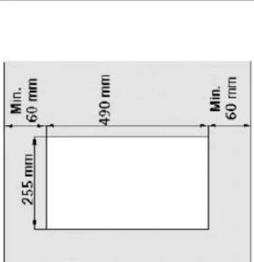
INSTALLATION OF YOUR COOKER
| 60 cm |  |  | 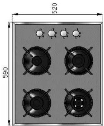 |  |
| 45 cm 30 cm | 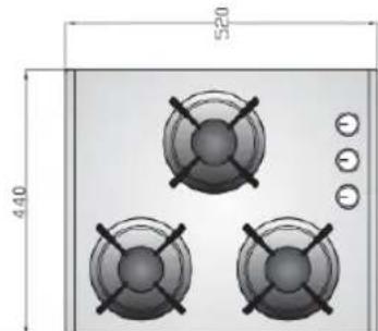 |  |  |  |
 |  |  |  | |
 |  |
natural_image
Technical drawing of four circular components with cross-bracing, one large circle, and three cross-bracing fans (no text or symbols)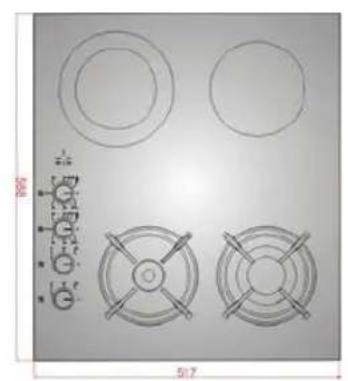
natural_image
Technical drawing of a mechanical component with four circular features and a central cross-shaped component (no text or symbols)1- This appliance must be installed by a competent person and with particular attention to air circulation.
2- The housing must be heat resistant to a temperature of 95 °C as per EEC directives
| 90 cm | 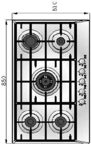 |  | 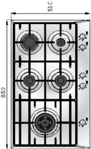 |  |
| 70 cm |  |  |  |  |
ELECTRICAL CONNECTION and SECURITY
- Your cooker requires a 13 or 16 Amp fuse. If necessary, installation by a qualified electrician is recommended.
- Your oven is adjusted in compliance with 230Volt AC, 50 Hz (for SA will be 220-240V, 50-60 Hz), electrical supply, and requires a 16 Amp (for England 13 Amp) fuse. If the mains are different from this specified value, contact an electrician or your authorised service.
- Electrical connection of the hob should only be made using sockets with Earth system installed (for England B.S. Approved sockets with Earth system), and in compliance with Regulations. If there is no proper socket with Earth in place, immediately contact a qualified electrician. The Manufacturer will not be responsible for damage or injuries that can arise because of inappropriate supply outlets with no earth system. If the ends of the electrical connection cable is open, according to the appliance type, make a proper switch installed in the mains by which all ends can be disconnected in case of connecting / disconnecting from / to the mains.
- If your electric supply cable gets defective, it should definitely be replaced by the authorized service or qualified electricians in order to avoid from the dangers
- Electrical cable shouldn't touch the hot parts of the appliance.
GAS CONNECTION and SECURITY
- Fit the clamp to the hose. Push one of the hose until it goes to the end of the pipe y heating in boiling water, and tighten the clamp with screw driver.
- For soundness testing; ensure that the gas controls are closed,
- Apply only Approved Leak Detection solutions to the connections for leaks.
- If the hob is installed above a cupboard or openable drawer, a heat protection panel must be installed under the hob with a minimum 15 mm clearance.
- Please use flexible hose for gas connection.
Caution! Make the oven connection to the gas inlet valve, the hose length must be short and be sure that there is no leakage.
The hose used sholud not be longer than 125 cm for safety.
RE-INSPECT THE GAS CONNECTION.
DO NOT MAKE GAS HOSE and ELECTRICAL CABLE OF YOUR COOKER GO THROUGH THE HEATED AREAS, SPECIALLY THROUGH THE REAR SIDE OF THE COOKER. DO NOT MOVE GAS CONNECTED COOKER. SINCE THE FORCING SHALL LOOSEN THE HOSE, GAS LEAKAGE MAY OCCUR
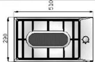
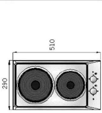
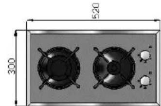
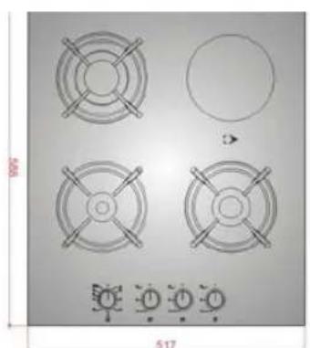
| SPECIFICATIONS | BUILT-IN HOB 60 cm | TABLE TOP HOB 60 cm | BUILT IN GLASS HOB DOMINO 30 cm | BUILT-IN GLASS HOB 60 cm | BUILT-IN GLASS HOB 70 cm | BUILT-IN GLASS HOB 90 cm | BUILT-IN HOB 45 cm |
| OUTER WIDTH | 580 mm | 580 mm 520 m | m 520 mm | 520 mm 520 mm | 440 mm | ||
| OUTER DEPTH | 510 mm | 510 mm 300 m | m 590 mm | 690 mm 860 mm | 510/520mm | ||
| OUTER HEIGHT | 105 mm | 100 mm 107 m | m 107 mm | 119 mm 119 mm | 98/106 mm | ||
| SUPPLY VOLTAGE | 220-240V AC, 50-60 Hz | 220-240V AC, 50-60 Hz | 220-240V AC, 50-60 Hz | 220-240V AC, 50-60 Hz | 220-240V AC, 50-60 Hz | 220-240V AC, 50-60 Hz | 220-240VAC, 50-60Hz |
| HOT PLATE / VITROCERAN HILIGHT (OPT) | 1000 W (opt) | 1000 W (opt) | - | 1200W-1800W (Opt) | - | - | - |
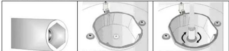
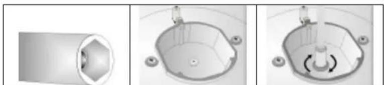
To adjust your oven acc. to the gas type, make the adjust. for reduced flame carefully by turning with a small scredriver as shown below on the scr. in the mid. of the gas cocks as well as nozzle changes.
Before making the connections of the appliance
Before starting to use the appliance, read the user manual of the appliance carefully. In this user Manual, there are important information regarding your, our customers security, how you will use it and how you will make its maintenance.
Note: Some of the features specified in the Manual may not be available in your appliance. This user manual is prepared for more than one model.
| Recommended Flame Gas Cock Adjustment: | from G30 to G20,G25 from G20,G25 to G30 |
| From LPG to Nat.gas from Nat.gas to LPG | |
| Rapid Burner 3 turns anticlockwise | 3 turns clockwise |
| Semi-Rapid Burner 2,5 turns anticlockwise | 2,5 turns clockwise |
| Auxiliary Burner 2 turns anticlockwise | 2 turns clockwise |

natural_image
Technical illustration of a mechanical assembly with spherical components and a tool (no visible text or symbols)| BURNER INJECTOR VALUES ACCORDING TO THE GAS TYPE | LPG | Natural Gas | ||
| G30-30 mbar | G20-20 mbar | |||
| Rapid Burner | Injector | mm | 0.85 | 1,15 |
| Power | KW | 3,00 | 2,770 | |
| Gas Flow | gr/h m3/h | 236 | 0,253 | |
| Wok Burner | Injector | mm | 0.96 | 1,30 |
| Power | KW | 3,600 | 3,350 | |
| Gas Flow | gr/h m3/h | 315 | 0,332 | |
| Semi-Rapid Burner | Injector | mm | 0.65 | 0,97 |
| Power | KW | 1,780 | 1,780 | |
| Gas Flow | gr/h m3/h | 140 | 0,167 | |
| Auxiliary Burner | Injector | mm | 0.50 | 0,72 |
| Power | KW | 0.88 | 0,990 | |
| Gas Flow | gr/h m3/h | 70 | 0,092 | |
IMPORTANT WARNINGS
- The setup conditions is written on the sticker rating label and also you will find your product information about gas type (LPG or NG)
- If the current rate of the fuse in your installation is less than 16 Amp, make a qualified electrician fit a 16 Amp fuse.
- Since the plug of your cooker has earthing system, ensure using socket with earth system. If it is used without earth system, our firm is not responsible for any loss which may arise
- Keep the gas hose and electrical cable of your oven away from the hot areas, do not let them touch the appliance. Keep them away from sharp sides and heated surfaces.
- If the supply cord is damaged, it must be replaced by the manufacturer its services agent or simulary qualified persons in order to avoid hazard.
- Please connect your appliance with a suitable main valve
- Connect your cooker to LPG or NG cock in shortest way and without any leakage. Min. 40 cm Max. 125 cm
- When making gas leakage check, never use any flame type like those of lighter, matches, cigarette fire or similar ones.
- Usage of your appliance creates moisture and heath in the room it is placed, make sure that your kitchen is ventilated well.
Maintain the natural ventilation ducts properly Or use cooker hood devices
- When the cooker is being used, the reachable parts may be hot, Do not touch to hot parts directly and keep children
- Before starting to use your appliance, keep curtain, tulle, paper or inflammable things away from your appliance. Do not keep combustible or inflammable things in or on the appliance.
- For disconnection from the supply mains having a contact separation in all poles that provide full disconnection, must be incorporated in fixed wiring in accordance with the wiring rules.
- Gas tapes are secured by locks. Do not turn before pressing the button.
- Do not use cooker in potentially explosive atmospheres.
- Pay attention to minimum health and safety requirement.
- The glass ceramic can be damaged by objects falling onto it.
- Built-in appliances may only be used after they have built in to suitable built-in units and work surfaces that meet standards.
- If the surface is cracked, switch off the appliance to avoid the possibility of electric shock, for hob surfaces of glass ceramic or similar material which protect live parts
- Pay attention to health and safety requirements – do not leave children un-supervised when cooking.
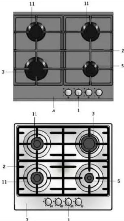
DESCRIPTION OF THE COOKER AND CONTROL PANEL
30 cm Domino Hobs 60 cm
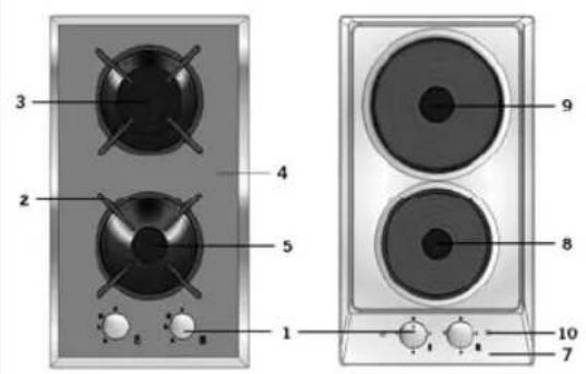
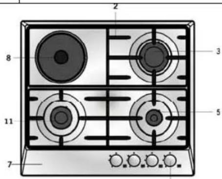
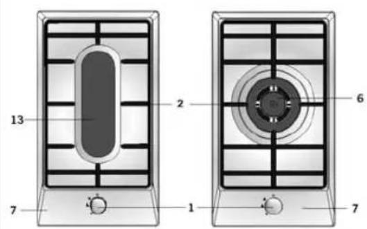

| 1 | Command Knobs |
| 2 | Grids |
| 3 | Rapid Burner |
| 4 | Glass Surface |
| 5 | Auxiliary Burner |
| 6 | Wok Burner |
| 7 | Hob Body |
| 8 | Hotplate |
| 9 | Hotplate |
| 10 | Indicator |
| 11 | Semi-Rapid Burner |
| 13 | Fish Burner |
| Table top hobs 70 & 90 cm | 1 | Command Knobs | ||
 |  | 2 | Grids | |
| 3 | Rapid Burner | |||
| 4 | Glass Surface | |||
| 5 | Auxiliary Burner | |||
| 6 | Wok Burner | |||
| 7 | Hob Body | |||
| 8 | Hotplate | |||
| 9 | Hotplate | |||
| 10 | Indicator | |||
| 11 | Semi-Rapid Burner | |||
| 12 | Aluminum profile | |||
USING HOB
Using Gas Burners: In order to obtain maximum output, be careful that the saucepan which will be used should be flat bottomed, and use the saucepans with dimensions given herein below. The valves controlling the gas cookers have special security mechanism. In order to light the cooker;
- Always press on the switch forward and bring it to flame symbol by turning anticlockwise (left).
All of the lighters shall operate and the cooker you controlled shall light only. Keep the switch pressed until ignition is performed. (OPTION)
- Press on the lighter button by pressing on the switch forward and turning anticlockwise (left). It means Closed Position.
| Rapid Cooker | 24 - 28 cm |
| Semi-rapid Cooker | 18 - 22 cm |
| Aux. Cooker | 12 - 18 cm |
| Closed | Fully | open |
In models with Gas Security System, when flame of the cooker is extinguished, control valve cuts off the gas automatically. (OPTION)
Using Electric Hotplates :
Make adjustment by rotating the switch clockwise according to the heat level you wish to use for your electric cooker. When the warning lamp lights over the switch, this means that the cooker is engaged. When the cooking is over bring
it back to ● position.
| 145 mm | LEVEL 1W 1000 W 1500 | 250 W | LEVEL 2 | 750 W | LEVEL 3 | 1000 W |
| 180 mm 500 W | W |
Electric Hotplates have standard of 3 temperature levels (as described herein above). depending on your cooker model that you can use from minimum to maximum temperature. When using first time, operate your electric hotplate in position 3 for 5 minutes. This will make the agent on your hotplate which is sensitive to heat get hardened by burning. Use flat bottomed saucepans which fully contact with the heat as much as you can, so that you can use the energy more productively.
Using Burners:
The our gas ovens top and bottom burner working system is one by one. When you want use your preference burner, before you must make press the tap knob and wait nearly 5-10 second. Then you can to inflame drought with automatic ignition or match. You must wait a few second after the inflame to have press by tap knob and after you can make allow the knob. If you can not made this operation you must try again.
Using Burners with Flame Failure Device fitted:
Select the burner required, depress and turn the gas control to maximum flame, hold down for 10 to 15 seconds. Once the flame is established the control knob can be released. If the burner fails to stay lit, repeat the procedure, but increase the length of time the control knob is held down
USING HOB FOR VITROCERAMIC
You operate the hob with the ring switches on the control panel of the hob. This switch regulates the energy in order to reach the desired temperature which is set by you.
In order to have a good cooking result from the hobs, the pans bottom should be as thick and flat as possible.
The bottom of the pans and cooking zones should be the same size. If possible, always place lids on the pans. Always place cookware on the cooking zone before it is switched on. To take advantage of the residual heat switch cooking zones off before the end of the cooking time.
Turn the knob clockwise for starting to operate. Temperature is set up by the knob position on the line gradually increasing up to max.(Single zone)
| Features |
| 140mm hilight 1200W |
| 180mm hilight 1800W |
MAINTENANCE and CLEANING
- Disconnect the plug supplying electricity for the cooker from the socket and cutoff the gas by closing the gas valve.
- While cooker is operating or shortly after it starts operating, it is extremely hot. You must avoid touching heating elements.
- Never clean the interior part, panel, grids, burner cover and all other parts of the cooker by the tools like hard brush, cleaning mesh or knife. Do not use abrasive, scratching agents and detergents.
- After cleaning the interior parts of the cooker with a soapy cloth, rinse it and then dry thoroughly with a soft cloth.
- Do not clean your cooker with steame cleaners.
- Wash the heads of the burners sometimes with soapy water and clean the gas ducts by means of a brush.
- Never use inflammable agents like acid, thinner and gasoline when cleaning your oven.
- Do not splash water onto the cooker.
- Clean removable burner parts with a hot soap solution. Do not clean in the dishwasher.
- Do not immerse burners or pan rests in water while they are still hot.
- Clean the glass surfaces with special glass cleaning agents for vitroceramic hobs
ESP
COCINA DE GAS CON ENCIMERA EMPOTRADA / DE SOBREMESA INSTRUCCIONES
Apreciado cliente,
natural_image
Four circular components with cross handles arranged in a 2x2 grid, one large circle on top, and three smaller circular elements below (no text or symbols)
natural_image
Technical drawing of a mechanical component with four circular features and two cross-shaped fans (no text or symbols)natural_image
Simple 3D illustration of a cylindrical object with a hexagonal hole, no text or symbols present.
natural_image
Simple line drawing of a basin with a faucet and two side sinks (no text or symbols)
natural_image
Top-down view of a mechanical component with circular motion arrows indicating rotation (no text or symbols)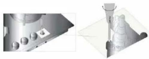
natural_image
Technical illustration showing a mechanical assembly and a precision tool tip (no text or symbols visible)MANUAL DE INSTRUÇÕES
Caro Cliente,
natural_image
Technical drawing of four circular components with cross-bracing, one large circle, and three cross-bracing circular features below (no text or symbols)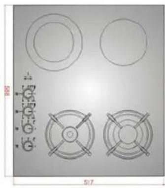
natural_image
Technical drawing of circular components and cross-shaped fans on a flat surface (no text or symbols)| 90 cm |  | 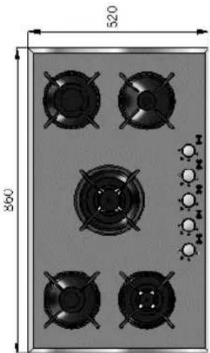 | 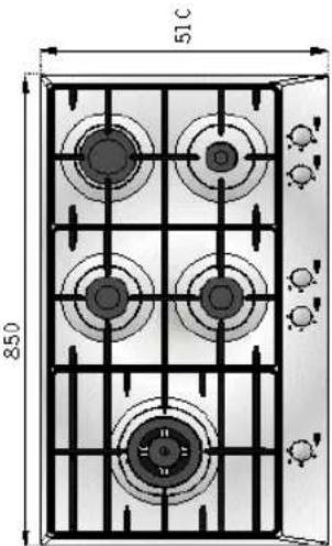 |  |
| 70 cm | 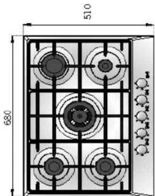 | 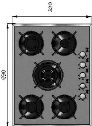 |  | 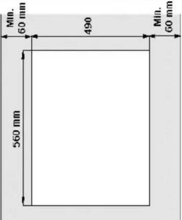 |
CARACTERÍSTICAS TÉCNICAS ESPECIFICAÇÕES
| LARGURA EXTERIOR | PLACA ENCASTRE | PLACA TABELA SUPERIOR | PLACA ENCASTRE DOMINO | PLACA ENCASTRE VIDRO 60 cm | PLACA ENCASTRE VIDRO 70 cm | PLACA ENCASTRE VIDRO 90 cm | PLACA ENCASTRE 45 CM |
| LARGURA EXTERIOR | 580 mm 5 | 80 mm 520 | mm 520 mm | 520 mm 520 mm | 440 mm | ||
| PROFUNDIDADE EXTERIOR | 510 mm 5 | 10 mm 300 | mm 590 mm | 690 mm 860 mm | 510/520 mm | ||
| ALTURA EXTERIOR | 85 mm 10 | 5 mm 116.5 | mm 116,5 | mm 116,5 mm | 98/106 mm | ||
| VOLTAGEM | 220-240V , 50-60 Hz | 220-240V , 50-60 Hz | 220-240V , 50-60 Hz | 220-240V , 50-60 Hz | 220-240V , 50-60 Hz | 220-240V AC, 50-60 Hz | |
| PLACA QUENTE 145 mm(opt) | 1000 W (opt) | 1000 W (opt) | - | - | - | -- |
natural_image
Three technical diagrams showing a cylindrical component, a square basin with a drain, and a circular basin with a central shaft (no text or symbols present)
natural_image
Illustration of a hand holding a tool with a curved arrow indicating rotation (no text or symbols)
| 2 | Grelha |
| 3 | Queimador Grande |
| 4 | Mesa trabalho |
| 5 | Queimador Pequeno |
| 6 | Queimador Wok |
| 7 | Painel de comando |
| 8 | Placas eléctricas |
| 9 | Placas eléctricas |
| 10 | Indicador Luminiso |
| 11 | Queimador Médio |
| 12 | perfil aliminium |
MODO DE UTILIZAÇÃO
Utilização a Gás:
| 145 mm | NIVEL 1W 1000 W 1500 W | 250 W | NIVEL 2 | 750 W | NIVEL 3 | 1000 W |
| 180 mm 500 W | W |
Opções
MANUTENÇAÕ E LIMPEZA


- BUILT-IN TABLE HOB GAS COOKER USER MANUAL
- ATTENTION!
- CONTENTS
- INSTALLATION OF YOUR COOKER
- ELECTRICAL CONNECTION and SECURITY
- GAS CONNECTION and SECURITY
- RE-INSPECT THE GAS CONNECTION.
- Before making the connections of the appliance
- IMPORTANT WARNINGS
- DESCRIPTION OF THE COOKER AND CONTROL PANEL
- USING HOB
- Using Electric Hotplates :
- Using Burners:
- Using Burners with Flame Failure Device fitted:
- USING HOB FOR VITROCERAMIC
- MAINTENANCE and CLEANING
- ESP
- COCINA DE GAS CON ENCIMERA EMPOTRADA / DE SOBREMESA INSTRUCCIONES
- Apreciado cliente,
- MANUAL DE INSTRUÇÕES
- Caro Cliente,
- MODO DE UTILIZAÇÃO
- Utilização a Gás:
- Opções
- MANUTENÇAÕ E LIMPEZA
Brand : SVAN
Model : SVE4BA
Category : Hot plate