EZN3261 - Security Camera EverFocus - Free user manual and instructions
Find the device manual for free EZN3261 EverFocus in PDF.


| Product Type | Outdoor IR Bullet IP Camera |
| Model | EZN3261 |
| Image Sensor | 1/3" Progressive Scan CMOS, 2 MP |
| Minimum Illumination | Color: 0.5 lux; B/W: 0.095 lux; 0 lux with IR LEDs on |
| Lens | 4.9~49 mm, 10x optical zoom, auto focus, DC Iris, F1.8~360C |
| Angle of View | Horizontal: 100° (Wide) ~ 27.3° (Tele); Vertical: 73.3° (W) ~ 20.4° (T); Diagonal: 129.1° (W) ~ 34.3° (T) |
| IR Distance | Up to 40 m / 131 ft with 12 IR LEDs |
| Day/Night | True Day/Night with removable IR-cut filter, auto switching |
| Wide Dynamic Range (WDR) | Yes |
| Video Compression | H.264, MPEG4, MJPEG (quad streams) |
| Maximum Resolution | 1920 x 1080 at 30 fps |
| Audio | Two-way audio, G.711 compression, line-in 3.5mm jack |
| Network | 10/100 Base-T Ethernet, PoE (IEEE802.3at Class 4), protocols: TCP/IP, IPv6, UDP, DHCP, NTP, DNS, DDNS, SMTP, SNMP, FTP, HTTP, HTTPS, PPPoE, UPnP, Bonjour, RTP, RTSP, RTCP, IGMP, ICMP, ARP, ONVIF, PSIA |
| Storage | Micro SD/SDHC card slot (up to 64 GB, Class 10 recommended) |
| Alarm I/O | 1 alarm input, 1 alarm output (4-pin terminal block) |
| Power Source | 12 VDC or PoE (IEEE802.3at Class 4) |
| Power Consumption | 11W (12 VDC) / 14W (PoE) |
| Operating Temperature | -40°C ~ 55°C (12 VDC); -20°C ~ 55°C (PoE) |
| Humidity | 20% ~ 80% (non-condensing) |
| Weather Resistance | IP66-rated |
| Dimensions | Φ105.5 x 328.7 mm (in-line); Φ105.5 x 123.5 x 295.49 mm (right angle) |
| Weight | 1.432 kg / 3.15 lbs |
| Adjustment Range | Pan: 360°, Tilt: 90°, Rotate: 360° |
| Compliance | CE, FCC, ONVIF, PSIA |
| Languages | Czech, Dutch, English, French, German, Japanese, Polish, Portuguese, Russian, Simplified Chinese, Spanish, Traditional Chinese |
Frequently Asked Questions - EZN3261 EverFocus
User questions about EZN3261 EverFocus
0 question about this device. Answer the ones you know or ask your own.
Ask a new question about this device
Download the instructions for your Security Camera in PDF format for free! Find your manual EZN3261 - EverFocus and take your electronic device back in hand. On this page are published all the documents necessary for the use of your device. EZN3261 by EverFocus.
USER MANUAL EZN3261 EverFocus
EZN Series Outdoor IR Bullet IP Camera
10x Optical Zoom, Auto Focus, True Day/Night, WDR, IP66
User's Manual
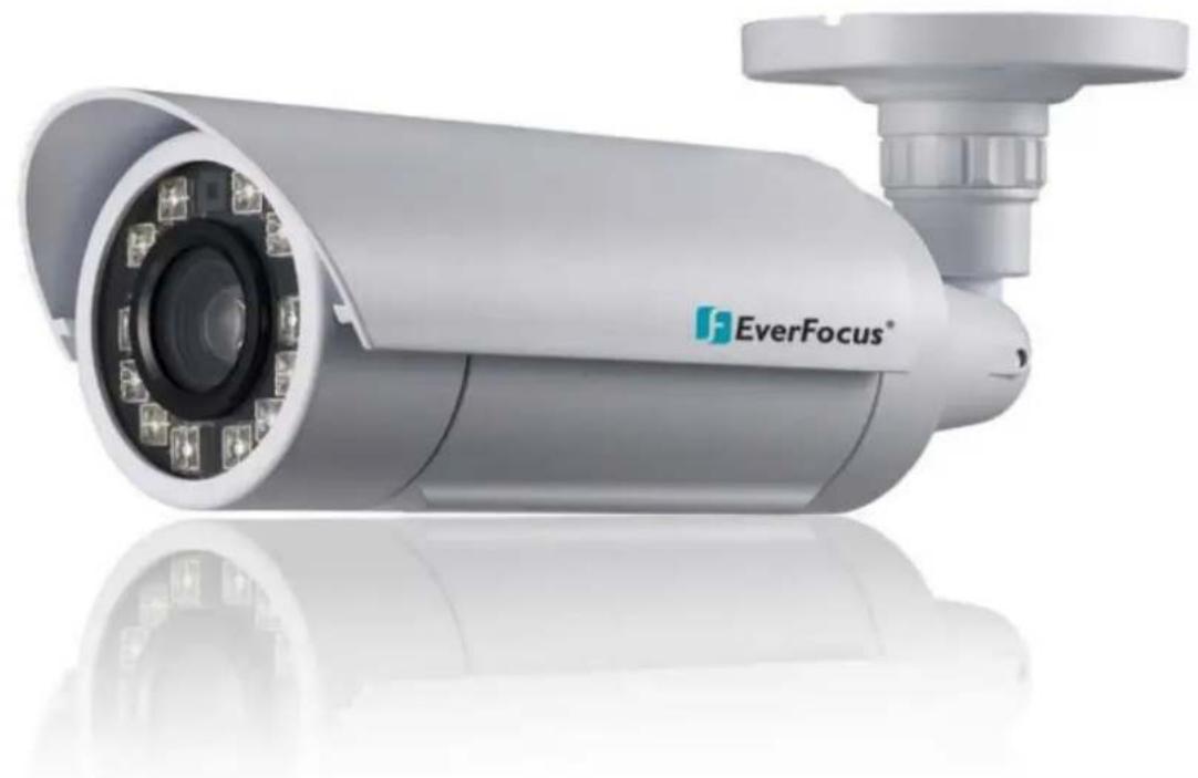
natural_image
Exterior view of a silver surveillance camera with 'EverFocus' branding, no visible text or symbols on the device itself.
EverFocus®
Copyright © EverFocus Electronics Corp,
Release Date: March, 2014

EverFocus®
Copyright © 2014 EverFocus Electronics Corp.
All rights reserved. No part of the contents of this manual may be reproduced or transmitted in any form or by any means without written permission of the EverFocus Electronics Corporation.
EverFocus
12F, No.79, Sec. 1, Shin-Tai Wu Road,
Hsi-Chih, Taipei, Taiwan
TEL: +886 2 2698 2334
FAX: +886 2 2698 2380
www.everfocus.com.tw
March, 2014
About this document
All the safety and operating instructions should be read and followed before the unit is operated. This manual should be retained for future reference. The information in this manual was current when published. The manufacturer reserves the right to revise and improve its products. All specifications are therefore subject to change without notice.
Regulatory Notices
FCC Notice "Declaration of Conformity Information"
This equipment has been tested and found to comply with the limits for a Class
A digital device, pursuant to part 15 of the FCC Rules. These limits are designed to provide reasonable protection against harmful interference in a residential installation. This equipment generates, uses and can radiate radio frequency energy and, if not installed and used in accordance with the instructions, may cause harmful interference to radio communications. However, there is no guarantee that interference will not occur in a particular installation. If this equipment does cause harmful interference to radio or television reception, which can be determined by turning the equipment off and on, the user is encouraged to try to correct the interference by one or more of the following measures:
- Reorient or relocate the receiving antenna.
- Increase the separation between the equipment and receiver.
- Connect the equipment into an outlet on a circuit different from that to which the receiver is connected.
- Consult the dealer or an experienced radio/TV technician for help.
Warning: Changes or modifications made to this equipment, not expressly approved by EverFocus or parties authorized by EverFocus could void the user's authority to operate the equipment.
This device complies with part 15 of the FCC Rules. Operation is subject to the following two conditions:
(1) This device may not cause harmful interference, and
(2) This device must accept any interference received, including interference that may cause undesired operation.
EverFocus Electronics Corp.
12F, No. 79, Sec. 1, Shin-Tai Wu Rd., Hsi-Chi,
Taipei Hsien, Taiwan, R.O.C.
EZN Series cameras comply with CE and FCC.
Precautions
- Do not install the camera near electric or magnetic fields.
Install the camera away from TV/radio transmitters, magnets, electric motors, transformers and audio speakers since the electromagnetic fields generated from these devices may distort the video image or otherwise interfere with camera operation.
- Never disassemble the camera beyond the recommendations in this manual nor introduce materials other than those recommended herein.
Improper disassembly or introduction of corrosive materials may result in equipment failure or other damage.
- Try to avoid facing the camera toward the sun.
In some circumstances, direct sunlight may cause permanent damage to the sensor and/or internal circuits, as well as creating unbalanced illumination beyond the capability of the camera to compensate.
- Keep the power cord away from water and other liquids and never touch the power cord with wet hands.
Touching a wet power cord with your hands or touching the power cord with wet hands may result in electric shock.
- Never install the camera in areas exposed to oil, gas or solvents.
Oil, gas or solvents may result in equipment failure, electric shock or, in extreme cases, fire.
- Cleaning
For cameras with interchangeable lenses, do not touch the surface of the sensor directly with the hands. Use lens tissue or a cotton tipped applicator and ethanol to clean the sensor and the camera lens. Use a damp soft cloth to remove any dirt from the camera body. Please do not use complex solvents, corrosive or abrasive agents for cleaning of any part of the camera.
- Do not operate the camera beyond the specified temperature, humidity or power source ratings.
Use the camera at temperatures within -40^ 55^ / -40^ 131^ (12 VDC) or -20^ 55^ / -4^ 131^ (PoE), and humidity between 20% and 80%; this device is not rated as submersible. The input power source is 12 VDC / PoE. Be sure to connect the proper +/ - polarity and voltage, as incorrect polarity or too high a voltage will likely cause the camera to fail, and such damage is not covered by the warranty. The use of properly fused or Class 2 power limited type supplies is highly recommended.
- Mounting
Use care in selecting a solid mounting surface which will support the weight of the camera plus any wind, snow, ice or other loading, and securely attach the camera to the mounting surface using screws and anchors which will properly support the camera. If necessary (e.g. when mounting to drop ceilings) use a safety wire to provide additional support for the camera.
TABLE OF CONTENTS
- Introduction ...... 1
- Features 2
- Physical Description .... 3
3.1 Cables....3
3.2 5-Axis Button ....4
- Installation 5
4.1 Packing List....5
4.2 Basic Installation 6
4.2.1 Mounting and Wiring 6
4.2.2 Inserting a Micro SD Card....9
- Accessing the User Interface.... 10
5.1 Checking the Dynamic IP Address....10
5.2 Settings for Microsoft Internet Explorer....12
5.3 Connecting the Camera to the Network....14
5.4 Live View Window....16
- Playback....20
6.1 Remote Playback Using Playback Page....20
6.2 Setting Up the Playback Function....22
6.2.1 Inserting / Removing the Micro SD Card 22
6.2.2 Testing the Playback Function 23
6.3 Playing Back Using ARV Viewer 25
- Settings 26
7.1 System Settings....27
7.1.1 Network 27
7.1.2 Date / Time....33
7.1.3 Storage....34
7.1.4 Display and Overlay 36
7.1.5 System Maintenance....38
7.1.6 System Information 41
7.1.7 User 42
7.1.8 Black/White List 44
7.2 Camera Settings 45
7.2.1 Streaming and Audio....45
7.2.2 Profile 48
7.2.3 Camera 50
7.2.4 Schedule....53
7.2.5 Image 54
7.3 Event Settings 55
7.3.1 Event Wizard....55
7.3.2 Event....56
7.3.3 Notification 60
7.4 Link to Smart Phone App 63
-
Upgrading Firmware Using IP Utility 64
-
Specifications 66
-
Troubleshooting 68
Appendix 71
1. Introduction
The EZN series bullet IP camera comes with two models: 2 MP and 3 MP, providing up to 30 fps at 2048 x 1536 viewing resolution. Equipped with an auto focus 10x optical zoom lens, the series can provide the desired field of view with superior video quality in precision focus.
The EZN series supports quad streams from H.264, MPEG4 or MJPEG. Featured with a weather-resistant (IP66) housing plus 12 IR LEDs for enabling the night visibility of up to 40 meters, the cameras meet a wide variety of needs for outdoor surveillance.
The EZN series bullet IP camera features the Wide Dynamic Range (WDR) function, which can provide clear images even under back light circumstances where intensity of illumination can vary excessively. The DNR (Digital Noise Reduction) function is designed for reducing the noises in the images, allowing the camera to better distinguish between real motion and image noise, and thus results in a possibility to store more video evidence on the connected storage devices.
A built-in micro SDHC card slot and Power over Ethernet (IEEE802.3at Class 4) features are also provided. You can power the camera over the network or by connecting the camera to a 12 VDC power supply. Since the series conforms to ONVIF / PSIA for compatibility with other network video devices, it interoperates with a wide variety of hardware and software systems. You can also use EverFocus Mobile Applications to remotely view the live views of the cameras through your handheld devices; or use EverFocus CMS to remotely manage multiple IP devices connected on the network. The EZN series bullet IP camera is the ideal solution for your outdoor surveillance needs.
The EZN Series Models
| Model Name | Megapixel | 10x Optical Zoom | Auto Focus | WDR |
| EZN3261 | 2 MP | Yes | Yes | Yes |
| EZN3361 | 3 MP | Yes | Yes | Yes |
System Requirement
Before installing, please check that your computer meets these system requirements.
• Operating System: Microsoft Windows XP / Vista (32-bit) / 7 (32-bit)
• Microsoft Internet Explorer 7 or above
Note: For using the Internet Explorer, some settings are required. Please refer to 5.2 Settings for Microsoft Internet Explorer.
2. Features
• 1/3" Progressive scan CMOS
• Quod streams from H.264, MPEG4 or MJPEG
- Up to 30 fps at 1920 × 1080 (EZN3261)
Up to 30 fps at 2048 × 1536 (EZN3361)
• 10x Optical Zoom
- 10x Digital Zoom
- Auto Focus
• Extended IR range of up to 40-meter / 131-foot with 12 LEDs
• Weather-resistant (IP66)
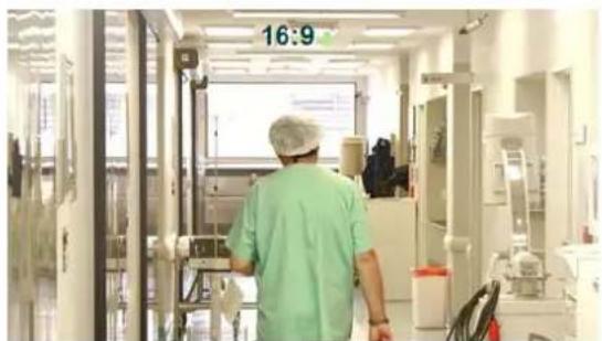
• Hallway Display (9:16)
• Built-in micro SD / SDHC card slot (see Appendix for the tested card brands)
• True Day/Night functionality with automatic IR filter operation
- Split glass to prevent internal IR reflections
- Cable management for protecting the cable within the bracket
- E-Z lock ring at the base is designed with easy to grip tabs to firmly clamp the camera in place, plus a set screw for security
- BNC video output to simplify the on-site installation and verification
• 3-axis mechanism (pan / tilt / rotate)
• One alarm input and output
- Two-way audio
- Multiple profiles for image settings
- Wide Dynamic Range (WDR)
• Digital Slow Shutter (DSS)
• 2D / 3D Dynamic Noise Reduction (DNR)
- Motion Detection
- Privacy Mask
- Anti-Tampering
- Setup wizard for easy Web UI setting
- Endurable to low environment temperatures (-40°C \~ 55°C / -40°F \~ 131°F)
• 12 VDC / PoE
- Multi-languages on Web interface
• ONVIF / PSIA compliant
• Supports EverFocus CMS and Mobile Applications (iOS / Android)
3. Physical Description
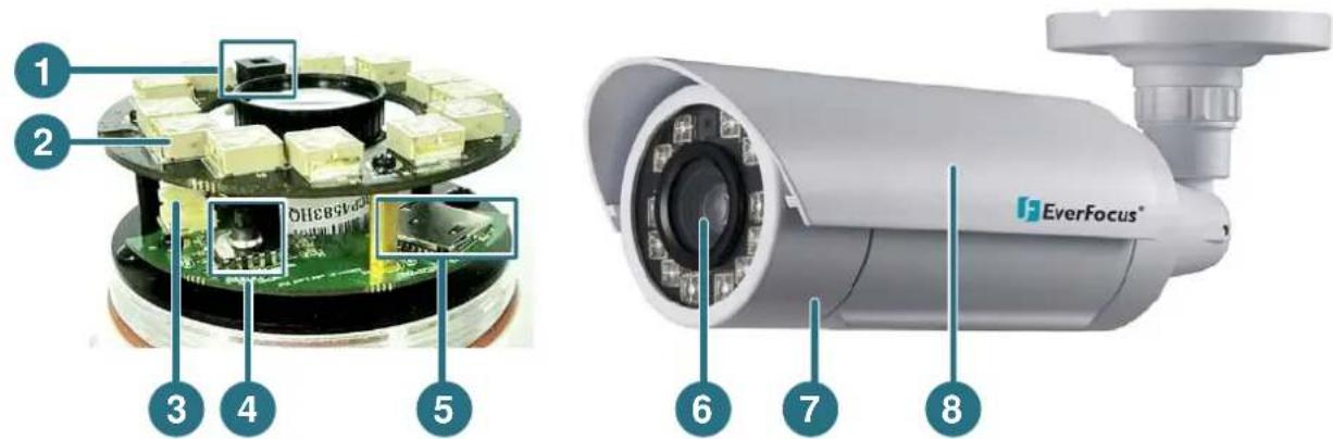
| No. | Name | Description |
| 1 | Light Sensor | Detects lights. |
| 2 | IR LEDs | 12 IR LEDs for infrared illumination in night vision applications. |
| 3 | Video Test Output | Connects to a handheld test monitor for adjusting camera focus / zoom / angles. |
| 4 | 5-Axis Button | For adjusting camera focus / zoom or restoring the camera to the factory default. See 3.2 5-Axis Button for more details. |
| 5 | Micro SD / SDHC Slot | Insert a micro SD / SDHC card (see Appendix for tested card brands). |
| 6 | Lens | 10x optical zoom, auto focus, DC Iris, F1.8-360C. |
| 7 | Camera Cover | Remove the cover for using the 5-Axis Button, inserting a micro SD card or connecting to a handheld test monitor. |
| 8 | Sunshield | Protect the camera from the direct rays of the sun. |
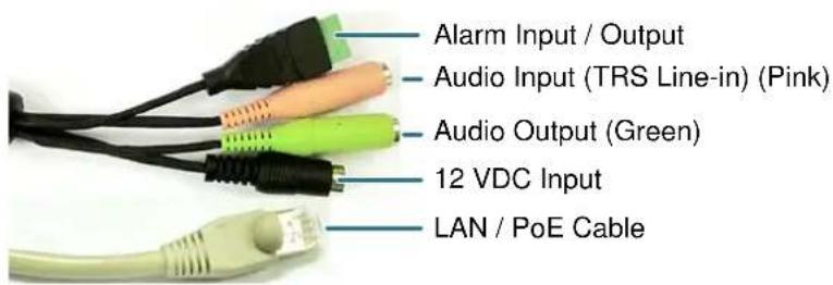
3.1 Cables
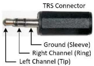
The Cables provide connections for Network, power, audio input / output and alarm input / output. Note that the audio-in cable features a line-in 3.5mm jack (TRS). Be sure to prepare microphones with TRS connector (see TRS Connector image below). Also, microphones with a (built-in) amplifier and external power supply are required.
Pin Assignment for Alarm Input / Output
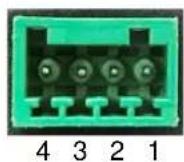
Pin 1: Alarm GND (-)
Pin 2: Alarm In (+)
Pin3: Alarm COM (-)
Pin4: Alarm Out (+)
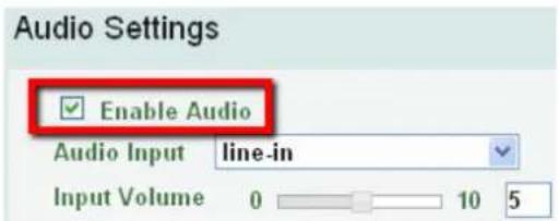
To activate the Audio function, the Enable Audio must be checked. See Audio Settings in 7.2.1 Streaming and Audio.
3.2 5-Axis Button
The 5-Axis Button is designed for manually adjusting zoom and focus, and restoring to factory default. You can also use the button to auto focus.
Note: If you have already inserted a desiccant bag inside the module, close the cover immediately in case of reducing the absorption capacity of the desiccant bag inside the camera. To replace a new desiccant bag, see Step3 in 4.2.2 Inserting a Micro SD Card.
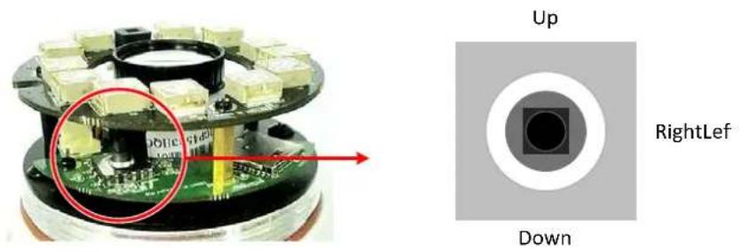
Focus: Push the button left or right.
Zoom: Push the button up or down.
Auto Focus: Press the button once.
Reset: Press and hold the button for 5 seconds.
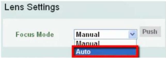
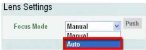
Note that if you select Auto from the Focus Mode drop-down list in the Lens Settings field (see 7.2.3 Camera), the camera will automatically adjust focus every time you push the button up or down to zoom.
4. Installation
4.1 Packing List
Please check that there is no missing item in the package before installing.
• EZN Series Camera x 1 • 4-Pin Terminal Block x 1
- Quick Mounting Ring x 1
- Test-Out Cable x 1
- RJ-45 Connector x 1
- Software CD x 1
- Desiccant Bag x 1
- Quick Installation Guide x 1
- Mounting Kit x 1
- Long Screw x 4 (for attaching the Quick Mounting Ring to the mounting surface)
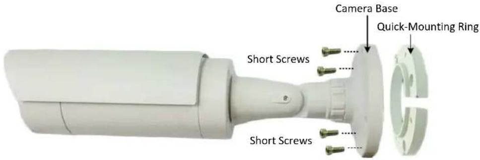
- Short Screw x 4 (for connecting the Camera Base to the Quick Mount Ring)
- Screw Anchor x 4 (in conjunction with Long Screw)
- Hexagon Key x 1 (for adjusting the camera position)
- Hexagon Wrench x 1 (for screwing the set screw)
- Plug x 1 (inserting to the Quick Mounting Ring for through-the-wall installation)
Note:
- Equipment configurations and supplied accessories vary by country. Please consult your local EverFocus office or agents for more information. Please also keep the shipping carton for possible future use.
- Contact the shipper if any items appear to have been damaged in the shipping process.
4.2 Basic Installation
This section will introduce the basic installation on mounting / wiring the camera, inserting a micro SD card and adjusting camera angles.
4.2.1 Mounting and Wiring
Follow the steps below for mounting and wiring the camera.
- Before screwing the camera to the wall, drill four holes on the wall according to the hole-positions on the supplied Quick-Mounting Ring. If you wish to run the wires through the wall, drill another hole in the middle of the circular area within the Quick-Mounting Ring.
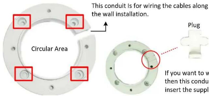
If you want to wire the cables through the wall, then this conduit will not be used. You can insert the supplied Plug into the conduit.
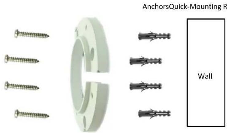
- Push the four supplied Anchors into the four holes on the wall. Place the Quick-Mounting Ring against the anchoring surface so that the holes line up. Screw the Quick-Mounting Ring to the wall using the supplied Long Screws.
- Screw the Camera Base to the Quick-Mounting Ring using the supplied four Short Screws.
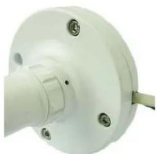
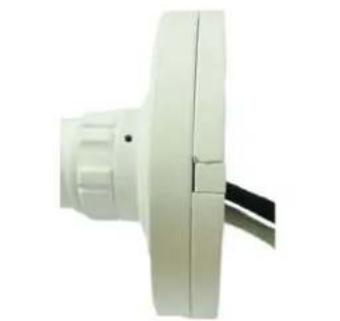
You can wire the cables from the side of the camera or through the wall.
natural_image
Close-up of a white mechanical component with mounting holes and a central shaft (no visible text or symbols)Wire the cables from the side of the camera
natural_image
Close-up of a white industrial air duct or fan component with a black cable inserted (no visible text or symbols)Wire the cables through the wall
- Connect the network, power and other cables to the related devices. Please refer to 3.1 Cables.
- Optionally insert a micro SD / SDHC card into the card slot (see 4.2.2 Inserting a Micro SD Card).
Note: After opening the camera cover for inserting the micro SD card, you have to stick the applied desiccant bag inside the camera.
- Access the camera live view. Please see 5. Accessing the User Interface. Or connect a handheld test monitor to the Video Test Output on the camera module for adjusting camera focus/zoom/angles. For details on how to adjust camera focus / zoom using the 5-Axis Button on the camera module, see 3.2 5-Axis Button.
7. Adjust the camera angles.
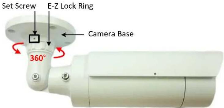
Pan Adjustment: Unscrew the Set Screw using the supplied Hexagon Wrench. Twist the Camera Base forcefully until it unscrews from the E-Z Lock Ring. Rotate the camera by 360° to the desired position and screw the E-Z Lock Ring until it locks against the Camera Base. Screw back the Set Screw.
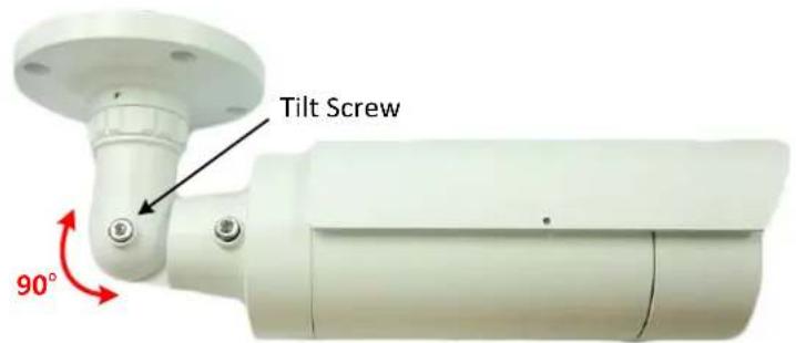
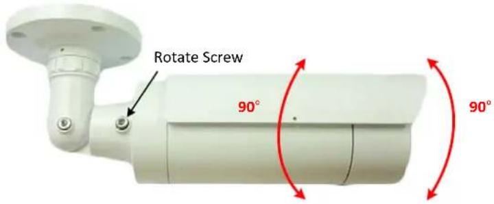
Tilt Adjustment: Loosen the Tilt Screw using the provided Hexagon Key and adjust the tilt angle by 90^ .
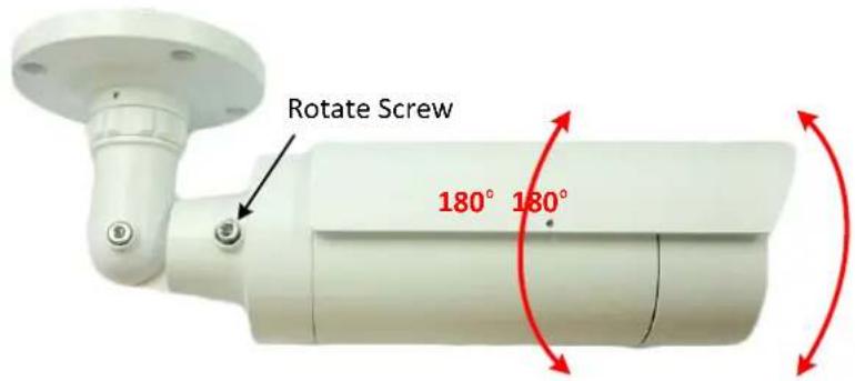
Rotational Adjustment: Loosen the Rotate Screws on both side of the camera body using the providing Hexagon Key and rotate the camera by 360^ ( 180^ to the left / 180^ to the right).
4.2.2 Inserting a Micro SD Card
You can optionally insert a micro SD card into the card slot on the camera module for recording videos. Please refer to Appendix for the tested card brands.
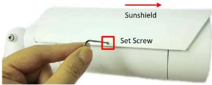
- Loosen the Set Screw on the Sunshield using the provided Hexagon Wrench and then slide the Sunshield out from the rail on the camera.
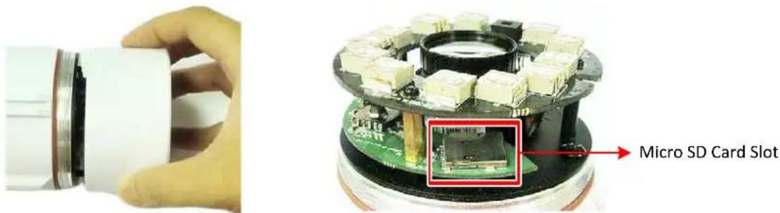
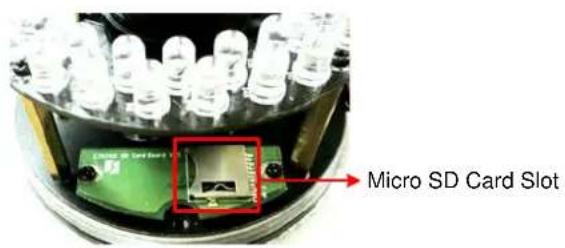
- Rotate and then remove the camera cover, and insert a micro SD card into the card slot.
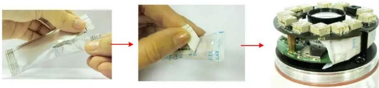
- Stick the supplied Desiccant Bag inside the camera.
natural_image
Three-step process showing a hand holding a transparent plastic film, moving through a chip to form a microchip (no text or symbols visible)Note: It's recommended to close the cover immediately in case of reducing the absorption capacity of the desiccant bag inside the camera.
- Firmly close the camera cover for waterproofing, slide the Sunshield back to the camera body and then screw the Set Screw.
5. Accessing the User Interface
This section explains how to access the Web interface of the camera for configuration.
5.1 Checking the Dynamic IP Address
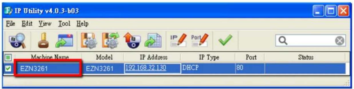
You can look up the IP address and access the Web interface of the camera using the IP Utility (IPU) software included in the software CD. Please connect the IP camera in the same LAN of your computer.
1. Install and then start the IPU program

The following IPU window appears. The IPU will automatically search the IP devices connected in the LAN.
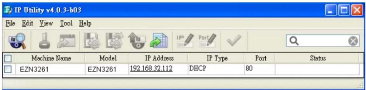
- To access to the Live View window, double click the IP address of the desired device, the login window pops up. Type the user ID and password to log in. By default, the user ID is user1 and the password is 11111111.
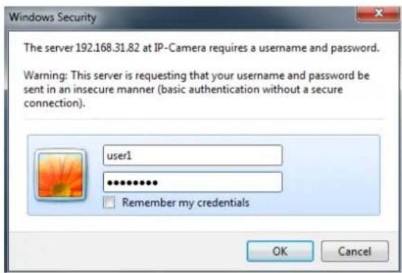
- Click OK, the Live View window appears.
Note:
- You might be required to download ActiveX for viewing the camera feed. If asked, click Yes.
-
To enable Remote Live View, Firmware Upgrade and ActiveX Prompt on Internet Explorer, some settings have to be complete. Please refer to 5.2 Settings for Microsoft Internet Explorer in the User's Manual.
-
To optionally configure the Machine Name, IP Address, IP Type or Port Number using the IPU:
a. Log in the camera by checking the desired model and then click the Log in icon. The Log in dialog box appears.
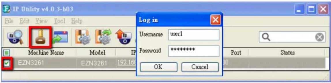
b. Type the Username and Password. Click the OK button, the Login status displays.
| Machine Name | Model | IP Address | IP Type | Port | Status |
| EZN3261 | EZN3261 | 192.168.32.112 | DHCP | 80 | Login |
Note:
- The default user ID is user1 and the default password is 11111111.
- If you select more than one camera that has the same user ID / password, you will be able to log in several cameras at once.
c. Right click the column to configure the settings. Click the Apply Changes √ button to apply and save the settings.
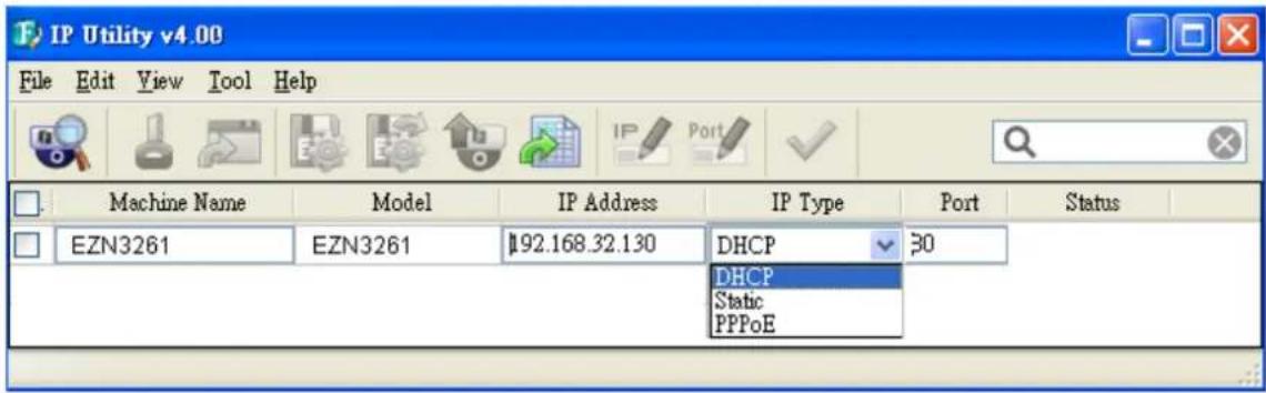
Note: Most networks uses DHCP to assign IP address, if you are unsure of your network settings, please consult your network administrators for configuration details.
5.2 Settings for Microsoft Internet Explorer
To enable Remote Live View, Firmware Upgrade and ActiveX Prompt on Internet Explorer, some settings have to be complete. Please follow the steps below:
- On the computer, click Start > Control Panel > System and Security > Action Center (click Change User Account Control Settings), the User Account Control Settings window appears. Adjust the slide bar to Never Notify and then click OK. Restart your computer if requested.
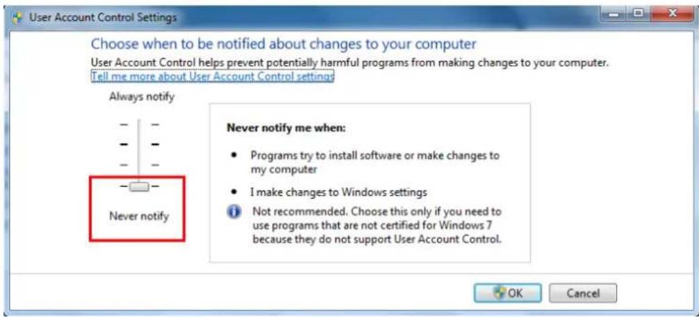
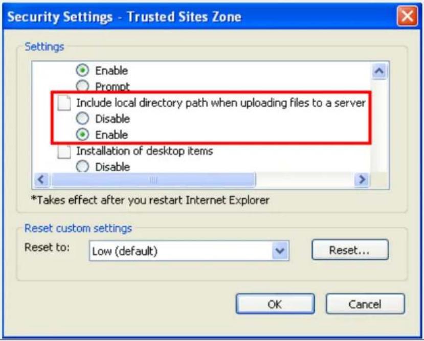
- Open the Internet Explore, click Tools > Internet Options > Security Tab > Custom Level, the Security Settings windows appears.
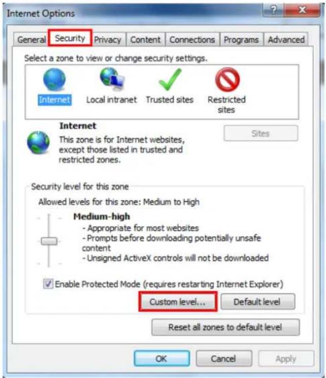
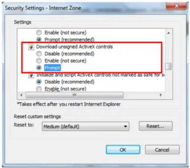
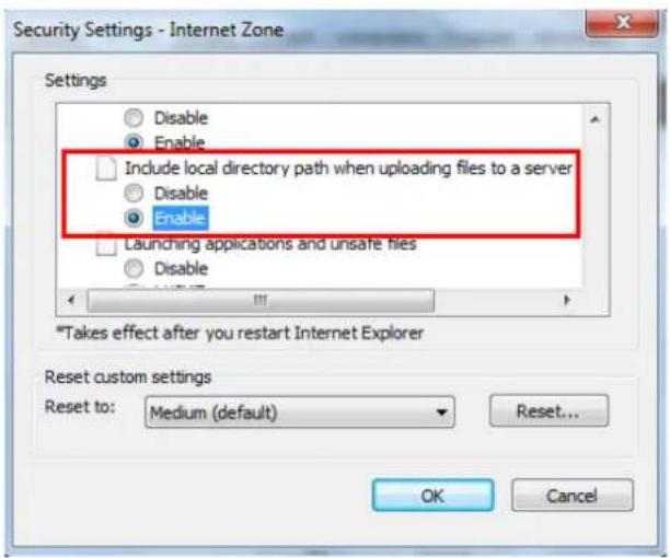
- In the Download unsigned ActiveX controls field, select Prompt. In the Include local directory path when uploading files to a server field, select Enable. Click OK.
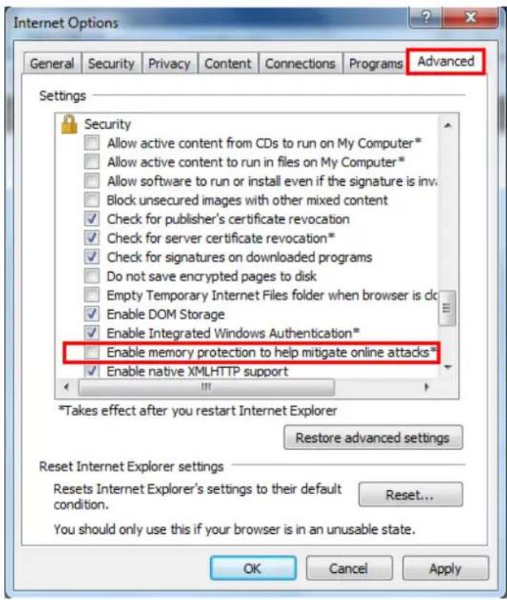
- In the Internet Options window, click the Advanced tab and then disable Enable memory protection to help mitigate online attacks. Click OK.
5.3 Connecting the Camera to the Network
There are three methods to connect the IP camera to the network: Router or LAN Connection, Direct High-Speed Connection and One-to-One Connection.
Router or LAN connection
This is the most common connection in which the IP camera is connected to a router and allows multiple users on and off site to see the IP camera on a LAN/WAN (Internet). The camera must be assigned an IP address that is compatible with its LAN. By setting up port forwarding on the router, you can remotely access the cameras from outside of the LAN via the Internet. To remotely access the Web interface of the IP camera, please refer to 7.1.1 Network (DDNS). To set up port forwarding, please consult the manual of the router.
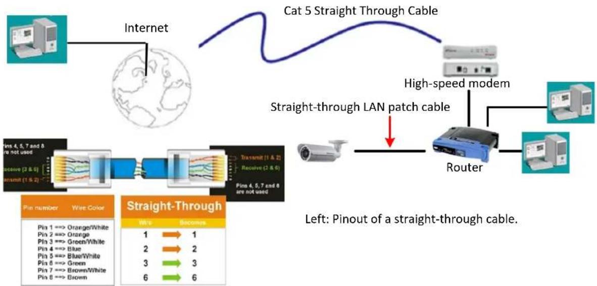
flowchart
graph TD
    A["Internet"] --> B["Cat 5 Straight Through Cable"]
    B --> C["High-speed modem"]
    C --> D["Router"]
    D --> E["Wire Color: Pin 4,5,7 and 8, receive (2 & 6)"]
    D --> F["Wire Color: Pin 4,5,7 and 8 are not used"]
    D --> G["Wire Color: Pin 4,5,7 and 8 are not used"]
    D --> H["Wire Color: Pin 4,5,7 and 8 are not used"]
    D --> I["Wire Color: Pin 4,5,7 and 8 are not used"]
    D --> J["Wire Color: Pin 4,5,7 and 8 are not used"]
    D --> K["Wire Color: Pin 4,5,7 and 8 are not used"]
    D --> L["Wire Color: Pin 4,5,7 and 8 are not used"]
    D --> M["Wire Color: Pin 4,5,7 and 8 are not used"]
    D --> N["Wire Color: Pin 4,5,7 and 8 are not used"]
    D --> O["Wire Color: Pin 4,5,7 and 8 are not used"]
    D --> P["Wire Color: Pin 4,5,7 and 8 are not used"]
    D --> Q["Wire Color: Pin 4,5,7 and 8 are not used"]
    D --> R["Wire Color: Pin 4,5,7 and 8 are not used"]
    D --> S["Wire Color: Pin 4,5,7 and 8 are not used"]
    D --> T["Wire Color: Pin 4,5,7 and 8 are not used"]
    D --> U["Wire Color: Pin 4,5,7 and 8 are not used"]
    D --> V["Wire Color: Pin 4,5,7 and 8 are not used"]
    D --> W["Wire Color: Pin 4,5,7 and 8 are not used"]
    D --> X["Wire Color: Pin 4,5,7 and 8 are not used"]
    D --> Y["Wire Color: Pin 4,5,7 and 8 are not used"]
    D --> Z["Wire Color: Pin 4,5,7 and 8 are not used"]
    D --> AA["Wire Color: Pin 4,5,7 and 8 are not used"]
    D --> AB["Wire Color: Pin 4,5,7 and 8 are not used"]
    D --> AC["Wire Color: Pin 4,5,7 and 8 are not used"]
    D --> AD["Wire Color: Pin 4,5,7 and 8 are not used"]
    D --> AE["Wire Color: Pin 4,5,7 and 8 are not used"]
    D --> AF["Wire Color: Pin 4,5,7 and 8 are not used"]
    D --> AG["Wire Color: Pin 4,5,7 and 8 are not used"]
    D --> AH["Wire Color: Pin 4,5,7 and 8 are not used"]
    D --> AI["Wire Color: Pin 4,5,7 and 8 are not used"]
    D --> AJ["Wire Color: Pin 4,5,7 and 8 are not used"]
    D --> AK["Wire Color: Pin 4,5,7 and 8 are not used"]
    D --> AL["Wire Color: Pin 4,5,7 and 8 are not used"]
    D --> AM["Wire Color: Pin 4,5,7 and 8 are not used"]
    D --> AN["Wire Color: Pin 4,5,7 and 8 are not used"]
    D --> AO["Wire Color: Pin 4,5,7 and 8 are not used"]
    D --> AP["Wire Color: Pin 4,5,7 and 8 are not used"]
    D --> AQ["Wire Color: Pin 4,5,7 and 8 are not used"]
    D --> AR["Wire Color: Pin 4,5,7 and 8 are not used"]
    D --> AS["Wire Color: Pin 4,5,7 and 8 are not used"]
    D --> AT["Wire Color: Pin 4,5,7 and 8 are not used"]
    D --> AU["Wire Color: Pin 4,5,7 and 8 are not used"]
    D --> AV["Wire Color: Pin 4,5,7 and 8 are not used"]
    D --> AW["Wire Color: Pin 4,5,7 and 8 are not used"]
    D --> AX["Wire Color: Pin 4,5,7 and 8 are not used"]
    D --> AY["Wire Color: Pin 4,5,7 and 8 are not used"]
    D --> AZ["Wire Color: Pin 4,5,7 and 8 are not used"]
    D --> BA["Wire Color: Pin 4,5,7 and 8 are not used"]
    D --> BB["Wire Color: Pin 4,5,7 and 8 are not used"]
    D --> BC["Wire Color: Pin 4,5,7 and 8 are not used"]
    D --> BD["Wire Color: Pin 4,5,7 and 8 are not used"]
    D --> BE["Wire Color: Pin 4,5,7 and 8 are not used"]
    D --> BF["Wire Color: Pin 4,5,7 and 8 are not used"]
    D --> BG["Wire Color: Pin 4,5,7 and 8 are not used"]
    D --> BH["Wire Color: Pin 4,5,7 and 8 are not used"]
    D --> BI["Wire Color: Pin 4,5,7 and 8 are not used"]
    D --> BJ["Wire Color: Pin 4,5,7 and 8 are not used"]
    D --> BK["Wire Color: Pin 4,5,7 and 8 are not used"]
    D --> BL["Wire Color: Pin 4,5,7 and 8 are not used"]
    D --> BM["Wire Color: Pin 4,5,7 and 8 are not used"]
    D --> BN["Wire Color: Pin 4,5,7 and 8 are not used"]
    D --> BO["Wire Color: Pin 4,5,7 and 8 are not used"]
    D --> BP["Wire Color: Pin 4,5,7 and 8 are not used"]
    D --> BQ["Wire Color: Pin 4,5,7 and 8 are not used"]
    D --> BR["Wire Color: Pin 4,5,7 and 8 are not used"]
    D --> BS["Wire Color: Pin 4,5,7 and 8 are not used"]
    D --> BT["Wire Color: Pin 4,5,7 and 8 are not used"]
    D --> BU["Wire Color: Pin 4,5,7 and 8 are not used"]
    D --> BV["Wire Color: Pin 4,5,7 and 8 are not used"]
    D --> BW["Wire Color: Pin 4,5,7 and 8 are not used"]
    D --> BX["Wire Color: Pin 4,5,7 and 8 are not used"]
    D --> BY["Wire Color: Pin 4,5,7 and 8 are not used"]
    D --> BZ["Wire Color: Pin 4,5,7 and 8 are not used"]
    D --> CA["Wire Color: Pin 4,5,7 and 8 are not used"]
    D --> CB["Wire Color: Pin 4,5,7 and 8 are not used"]
    D --> CC["Wire Color: Pin 4,5,7 and 8 are not used"]
    D --> CD["Wire Color: Pin 4,5,7 and 8 are not used"]
    D --> CE["Wire Color: Pin 4,5,7 and 8 are not used"]
    D --> CF["Wire Color: Pin 4,5,7 and 8 are not used"]
    D --> CG["Wire Color: Pin 4,5,7 and 8 are not used"]
    D --> CH["Wire Color: Pin 4,5,7 and 8 are not used"]
    D --> CI["Wire Color: Pin 4,5,7 and 8 are not used"]
    D --> CJ["Wire Color: Pin 4,5,7 and 8 are not used"]
    D --> CK["Wire Color: Pin 4,5,7 and 8 are not used"]
    D --> CL["Wire Color: Pin 4,5,7 and 8 are not used"]
    D --> CM["Wire Color: Pin 4,5,7 and 8 are not used"]
    D --> CN["Wire Color: Pin 4,5,7 and 8 are not used"]
    D --> CO["Wire Color: Pin 4,5,7 and 8 are not used"]
    D --> CP["Wire Color: Pin 4,5,7 and 8 are not used"]
    D --> CQ["Wire Color: Pin 4,5,7 and 8 are not used"]
Direct High-Speed Connection
In a Direct High-Speed Connection, the camera connects directly to a modem without the need for a router. You need to set the static or dynamic WAN IP address assigned by your ISP (Internet Service Provider) in the camera's configuration web pages. To access the camera, just type
"http://xxx.xxx.xxx.xxx", where xxx.xxx.xxx.xxx is the IP address given by your ISP. If you have a dynamic IP address, this connection may require that you use DDNS for a reliable connection. Please refer to 7.1.1 Network (DDNS).
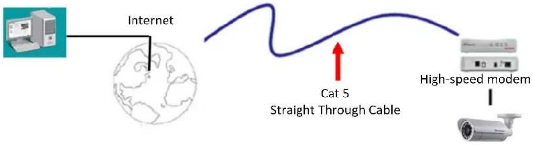
flowchart
graph LR
    A["Internet"] --> B["Cat 5 Straight Through Cable"]
    B --> C["High-speed modem"]
    C --> D["Satellite"]
One-to-One Connection (Directly from PC to IP Camera)
You can connect directly without using a switch, router or modem. However, only the PC connected to the camera will be able to view the IP camera. You will also have to manually assign a compatible IP address to both the computer and the IP camera. Unless the PC has another network connection, the IP camera will be the only network device visible to the PC. See the diagram below:
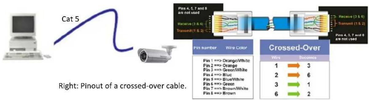
flowchart
graph LR
    A["Cat 5"] --> B["Wire Color"]
    B --> C["Transmit (1 & 2)"]
    C --> D["Transmit (3 & 6)"]
    D --> E["Pins 4, 5, 7 and 8 are not used"]
    B --> F["Pin number: Orange/White, Blue/White, Green/White, Brown"]
    F --> G["Crossed-Over"]
    G --> H["Wire: 1 → 3, 2 → 6, 3 → 1, 6 → 2"]
5.4 Live View Window
![EverFocus® Video Stream 1 View Size 640x480 English EZN3261 [ 10:05:00 03/11/2014 ] FPS:17/21 ZOOM:x1.18 Digital Zoom One Push Focus Manual Control Trigger Event Reset Alarm Lens Control ++ + -- - + ++ + -- - - Focus Speed 4X](/content/2026/06/1186584/images/ea38be141d6ebe143c263fce9a7d1fcf4722f03c5e9f2fc33dc920992f1ae993.jpg)
1. Live View

Click the Live View button to display the Live View window. If you experience video feed lag time (if connected via Internet), you can reduce the resolution or limit the number of streams. See 7.2.1 Streaming and Audio.
2. Playback
Click the Playback button to play back the recorded data directly from the on-camera SD / SDHC card. For this function to become active, you have to insert an SD / SDHC card into the SD / SDHC card slot on the camera (see 6.2 Setting up the Playback Function). For the tested card brands, please refer to Appendix.
3. Snapshot

Click the Snapshot button to take a snapshot. By default, the snapshot will be saved at C:\EverFocus. To change the location, see Record to Local in 7.1.3 Storage.
Note: For Microsoft IE10 and above users, some settings have to be complete to enable this function (see B. Snapshot/Record error message in 10. Troubleshooting).
4. Record

Click the Record button to start / stop recording the current video stream. By default, this icon is only for one-minute video recording and the recordings will be saved at C:\EverFocus. To change the recording time, see File Size in 7.1.3 Storage. To change the location, see Record to Local in 7.1.3 Storage. To record long-period recordings, please set up a recording schedule (7.3.2 Schedule Settings). To change the source video stream and recording format, see Recording and Snapshot Settings in 7.1.3 Storage.
Note: For Microsoft IE10 and above users, some settings have to be complete to enable this function (see B. Snapshot/Record error message in 10. Troubleshooting).
5. Speaker / Microphone

Click the Speaker and Microphone buttons to switch the sound on/off for the speakers and microphones respectively (if such external devices have been connected to the camera directly or via the network). To activate the Audio function, the Enable Audio must be selected. See Audio Settings in 7.2.1 Streaming and Audio. Note that the camera provides a line-in 3.5mm jack (TRS), therefore, TRS microphones with a (built-in) amplifier and external power supply are required.
6. Setting

Click the Setting button to enter the Settings page (see 7. Settings).
7. Wizard

Click the Wizard button to enter the Setup Wizard.
8. Hallway Display (9:16): Click the Rotate button

to rotate the live image. This function allows users to monitor vertically-oriented areas such as hallway, corridors and aisles.
natural_image
Interior view of a cleanroom facility with a worker in green uniform walking past equipment (no visible text or symbols)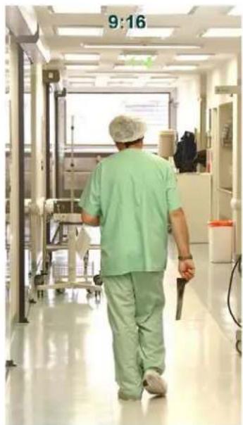
natural_image
Interior view of a hospital corridor with a medical staff member walking, no visible text or symbolsNote: To achieve the best 9:16 display effect, it's recommended to:
- Install the camera sideways by rotating the camera to the left or right by 90°.
- Select a 16:9 View Size (e.g. 1920x1080 / 1024x768).
- Use the Rotate button.
9. Video Stream
Select the Video Stream (Stream 1, Stream 2, Stream 3 or Stream 4) that will be displayed in the live view window on the bottom. Stream 2, Stream 3 and Stream 4 are only selectable if you have enabled the stream (see 7.2.1 Streaming and Audio). The default setting is Stream 1 only.
10. View Size
Use this to select the appropriate view size and shape of the live view window on the bottom. A smaller size might increase transmission speed and video quality.
11. Language
Click the Language drop-down list to select the desired language.
12. Digital Zoom
Click + - to zoom in / out the camera view up to 10x. Clicking on a magnified image will re-center the image around that point.
13. One Push
The One Push button can be displayed on the live view window by enabling the Show One Push Buttons function in the Live View Layout Settings (see 7.1.4 Display and Overlay). Click the
button to Auto Focus. To enable the Auto Focus button, you have to select Auto in
the Focus Mode drop-down list (see 7.2.3 Camera). When the Auto Focus function is enabled, the camera will automatically adjust focus every time you click the Zoom in/out buttons.
14. Manual Control
Click the Trigger Event button to trigger an event directly from the Live View window. If you have configured an event (in the Event List) that will trigger a reaction (like a recording) when a Manual Trigger event occurs, clicking this button will trigger that reaction. You can select what that reaction will be. You can, for instance, set the camera to record the audio/video feed to the SD card on board the camera. You can then click on the Playback button to open the Playback page and search for and play all such recordings that had been stored on the card. Such event actions will be effective once they have been configured in the Event List (see 7.3.2 Event).
Click the Reset Alarm button to reset the alarm output remotely.
15. Lens Control
The Lens Control buttons can be hidden on the live view window by disable the Show Lens Control Buttons function in the Live View Layout Settings (see 7.1.4 Display and Overlay). These buttons control the lens actions. Click and hold the icons to continuously focus closer or farther. Click the + - - - - - - - - - - - - - - - - - - - - - - - - - - - - - - - - - - - - - - - - - - - - - - - - - - - - - - - - - - - - - - - - - - - - - - - -
Note: If you select Auto from the Focus Mode drop-down list (see Lens Settings image above), the camera will automatically adjust focus every time you click the Zoom in/out buttons.
16. Status Display (info line that can be placed above video box or at bottom of page)
This shows the name of the camera that is currently active or being configured, current date/time and current frame rate. You can activate these info displays in the Overlay Text Settings (see 7.1.4 Display and Overlay).
17. Event signal icons (above video screen)
When an alarm or motion event is triggered, a signal icon will appear at the top right of the Live View window to alert the user.
Alarm event icon : When an alarm is triggered, this icon appears.
Motion detection icons : The colors of these motion event icons correspond to the colors of the motion trigger areas you have configured in the Motion Settings (see 7.3.2 Event). Recording icon : When the camera is recording to a PC-based folder, this icon appears.
6. Playback
You can remotely play back the recordings stored in the on-camera micro SD card on the Web interface, or play back the recordings stored in the computer using the ARV Viewer included in the software CD.
Playback is designed as a quick way to check recent recordings that were triggered by Events that were configured to "Record to SD Card" in the Event Management (see 7.3.2 Event).
Note: The Playback page is only accessible once the on-camera SD card is inserted and active. Please refer to Appendix for the tested card brands.
6.1 Remote Playback Using Playback Page
On the Live View Window, click the Playback button

to open the Playback page.
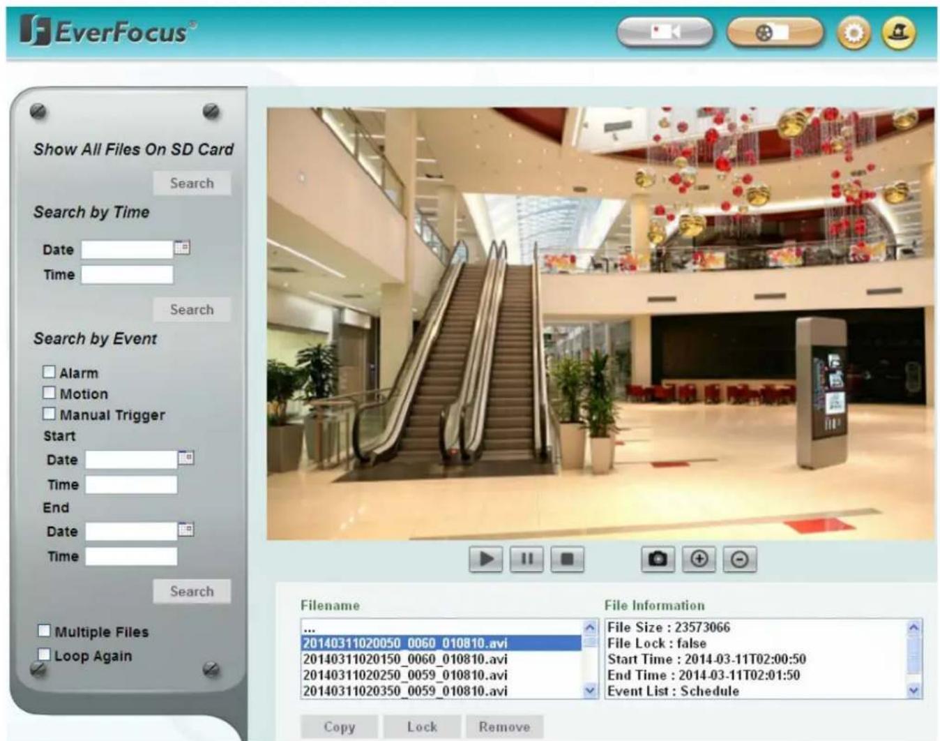
Search by File: Click the Search button to search for all recording files on the on-camera SD card.
Search results will be displayed in the Filename area.
Search by Time: Click the Date / Time column and select the date and time from which you want to search until the present moment. Click Search to get your search results, which will be displayed in the Filename area.
Search by Event: Select the type of Event recordings you want to search for (Alarm, Motion, Manual Trigger) and then click the Start Date / Time; End Date / Time column to select the Start Time date/time and the End Time date/time of your search. Click Search to get your search results, which will be displayed in the Filename area.
Multiple Files: Check this box if you want the video player to play all the files in the selected folder. The files will be displayed in the Filename area.
Loop Again: Check this box if you want the video player to play the selected file over and over again.
Play: Once you have opened the file's folder and have clicked on the file to highlight it, its details will be displayed in the File Information area. You can now click Play ▶ to play that specific file.
Pause: Click 11 to pause playing back.
Stop: Click ■ to stop playing back.
Snapshot: Click to take a snapshot.
Zoom Out: Click to zoom out.
Filename: This area will display a list of search results (recording files and folders). Folders (named with the recorded date) will be displayed first. Click on the folder and click on each subfolder until the recording files (.arv) in that folder is listed.
File Information: Click a file on the Filename list, the selected file information will be listed.
Copy: Click to copy the selected file to the computer-based folder of your choice. A browsing box will open so that you can search for the folder of your choice. You can use the ARV Viewer to play back the recordings recorded in your computer. For details on ARV Viewer, see 6.3 Playing Back Using ARV Viewer.
Lock: Click to lock the selected file. This will protect that file from being overwritten during any overwrite procedure. The file will thus be saved on the micro SD card indefinitely. However, the file will still be deleted if the micro SD card is ever formatted.
Remove: Click to delete the selected file.
6.2 Setting Up the Playback Function
Note that the Playback function will not be active until the user has inserted a micro SD card in the camera's micro SD card slot. The card may also have to be formatted in the Secure Digital Card field (see 7.1.3 Storage). For the tested card brands, please refer to Appendix.
6.2.1 Inserting / Removing the Micro SD Card
- To insert the SD card: Remove the camera cover and insert the SD card into the SD card slot before powering on the camera.
- To remove the SD card: Click the Remove button (System Settings > Storage > Secure Digital Card) when the camera is powered on, the SD card information "SD card is not mounted" will display and the Remove button will change to Attach, and then you may remove the SD card. If you want to insert the SD card again, insert the SD card and then click the Attach button.
After inserting the SD card into the SD card slot, the Playback button on the Live View page should be activated. If not, do the following:
- Click the Remove button, pull the card out and re-insert it.
- Click the Format button to format the card. NOTE: All data on the disk will be deleted if the Format button is clicked.
6.2.2 Testing the Playback Function
- To test the Playback function (this is not required), set up a "Manual Trigger" Recording Event by clicking Event Settings > Event.
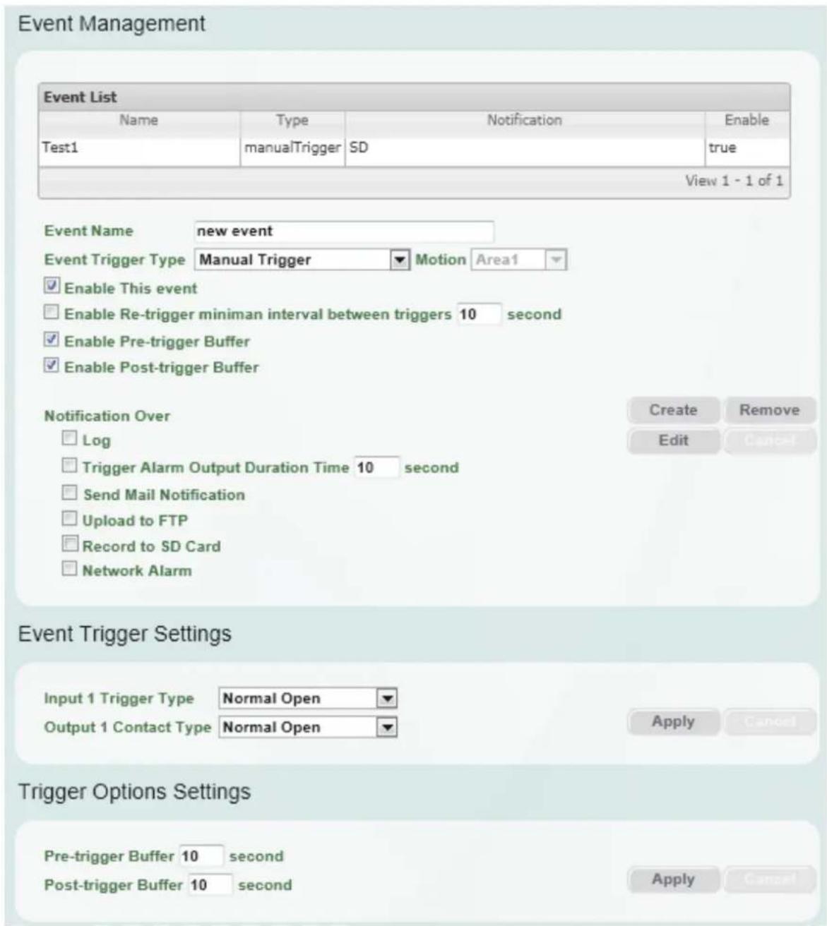
- Give the event a name, like "Test 1".
- In the "Event Triggered Type" field, click on Manual Trigger.
- Below this, check "Enable This Event", "Enable Post-trigger Buffer", and "Record to SD Card".
- To save your settings, click the Create button, and the Event will be listed in the Event List.
-
Look at the "Post-trigger Buffer" at the bottom to make sure the buffer time is set to 10 seconds. Click the Apply button.
-
Click theLiveView button to go back to the Live View page.
-
Get ready to click the Trigger Event button on the Live View page. Before you do, see if you can find something in the view screen that will give you a visual time marker. For instance, if you can get your hand in front of the camera's lens, get ready to count down on your fingers.
-
Click the Trigger Event button and slowly count down on your fingers in front of the lens (if you are able to do so – if not, try to find visual cues on the view screen that will help you to mark the moment you pushed the trigger). The recording period will be as long as the buffer time you selected – the default period is 10 seconds.
-
Click the Playback button to open the Playback page.
-
There are different ways to search for recording files on the camera's micro SD card (i.e. the Playback memory). For a recent recording like your test event, simply click the "Search" button under the "Show All Files on SD Card" header.
-
If the micro SD card is active and formatted correctly, the recording folder's name (the recording day's date) will appear in the Filename area. Click on this folder to open it. If there are sub-folders, click on the bottom one (the most recent would be at the bottom) until you can click on a file that cannot open to another sub-level and shows data in the File Information area to the right. This would be the file of the most recent recording event.
-
To play this file, click the Play button below the video box. The test footage you have recorded should start playing. Play time should be 10 seconds if you left the Post-trigger Buffer as 10 seconds.
6.3 Playing Back Using ARV Viewer
You can play back the recordings stored in the computer using the ARV Viewer

included in the
software CD. To store the recordings in the computer, please refer to Copy in 6.1 Remote Playback Using Playback Page.
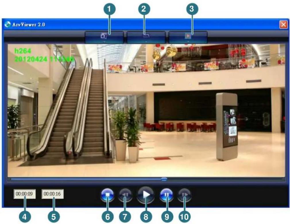
| No. | Item Name Descriptions | |
| 1 | Snapshot | Click to take and save a snapshot. |
| 2 | Load File | Click to load the recordings for playing back. |
| 3 | Convert ARV to AVI | Convert the recording from ARV format to AVI format. |
| 4 | Playback Time | Display the playback time. |
| 5 | Total Time of Recording | Display the total time of the recording. |
| 6 | Stop | Click to stop playing the recording. |
| 7 | Step Reverse | Click to display the previous frame. |
| 8 | Play | Click to play back the recording. |
| 9 | Pause | Click to pause the recording. |
| 10 | Step Forward | Click to display the next frame. |
7. Settings
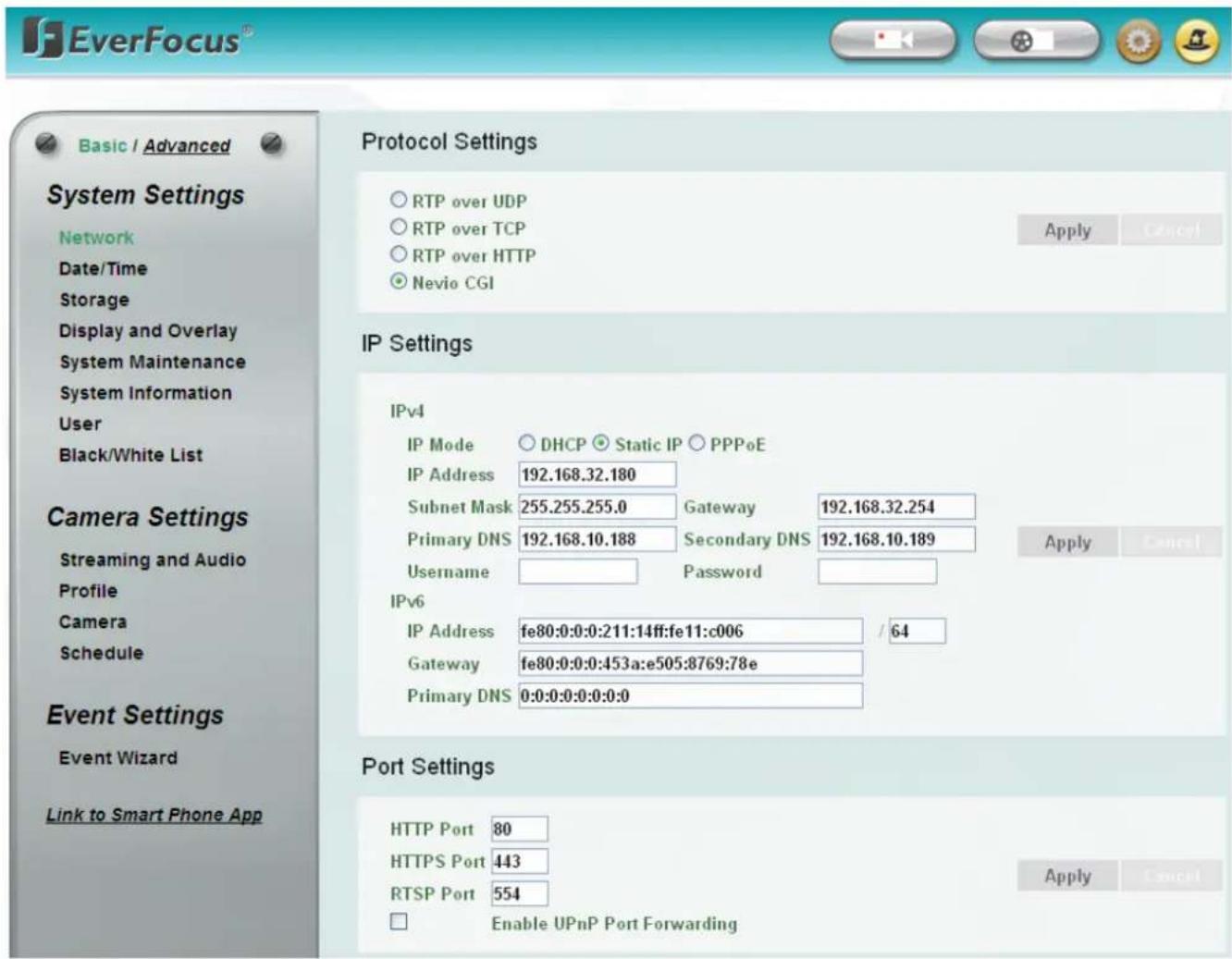
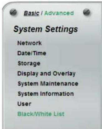
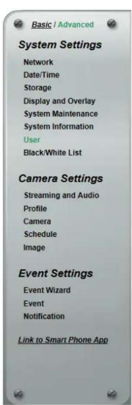
Click the Setting button on the Live View Window to enter the setting submenu. There are two tabs: Basic and Advanced on the left-side bar. You can set up the basic camera settings in the Basic tab. To further set up comprehensive camera settings, click the Advanced tab, which includes all the settings to be configured. The chapters below describe the detailed information of the Advanced tab.
7.1 System Settings
7.1.1 Network
Protocol Settings
RTP over UDP
RTP over TCP
© RTP over HTTP
Nevio CGI
IP Settings
IPv4
IP Mode DHCP Static IP PPPoE
IP Address 192.168.32.122
Subnet Mask 255.255.255.0 Gateway 192.168.32.254
Primary DNS 192.168.10.188 Secondary DNS 192.168.10.189
Username Password
IPv6
IP Address fe80:0:0:0:211:14ff:fec2:2270 /64
Gateway fe80:0:0:0:0:0:0
Primary DNS 0:0:0:0:0:0:0
Port Settings
HTTP Port 80
HTTPS Port 443
RTSP Port 554
Enable UPnP Port Forwarding
Multicast Settings
Enable Multicast
Port 50000
Multicast IP 239.238.144.152
Time to Live 5
Apply
DDNS Settings
Enable Service ISP
www.everfocusddns.com
IP Camera Name .everfocusddns.com
www.sitelutions.com www.dyndns.com www.no-ip.com
Record ID
Username
FQDN
Password
Apply
HTTPS Settings
Create Certicated Mode
Country Name
State or Province Name
Locality Name
Organization Name
Organization Unit Name
Common Name
Validity
Created Request
Install Signed Certicated
Install Certicated Info
Self-signed Certicated
Certificate Request
The Ground Truth image displays a single, solid horizontal line. According to Rule 2 (UNDERSCORE & LINE RULES), this is a stylistic or background line, not a placeholder underscore. Therefore, the OCR result must ignore it and output nothing or only meaningful text. The provided OCR content is "____", which consists of four underscores. This is an incorrect interpretation of the line as a placeholder, violating the rule that stylistic lines must be ignored. The OCR has hallucinated underscores where none should exist based on the GT's visual context. Hence, the OCR result is inconsistent with the Ground Truth.
[Non-Text]
(No text)
(No text)
(No text)
(No text)
(No text)
(1)
Day
(No text)
This image contains no text. The horizontal line is a stylistic or background element and must be ignored according to the rules.
(No text)
Property Remove
Property
Browse
Remove
Upload
Property Information
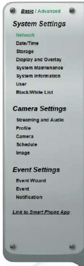
【Protocol Settings】 You can transmit the data stream from the IP cameras using the RTSP (Real Time Streaming Protocol) on the network. The RTSP is a protocol that allows you to access video streams by using the compatible media players. Click Apply to apply the changes or Cancel to cancel the changes and return to the previous settings.
■ RTP over UDP: The RTSP protocol uses UDP for camera data stream transmission.
■ RTP over TCP: The RTSP protocol uses TCP for camera data stream transmission.
■ RTP over HTTP: The RTSP protocol uses HTTP for camera data stream transmission.
■ Nevio CGI: This is EverFocus' protocol designed for EverFocus' IP devices. Select this protocol for camera data stream transmission.
【IP Settings】Enter the IPv4 / IPv6 details in this area, which applies to your system. Click Apply to apply the changes or Cancel to cancel the changes and return to the previous settings.
■ IPv4:
IP Mode: Refer to the network administrator for these settings of the server. Default: DHCP.
- DHCP: This setting lets the system use an automatically assigned (dynamic) IP address. This address can change under certain circumstances. For instance, when the camera's network switch/hub has to be rebooted. Do not assign to the DHCP server the same IP addresses used for the other network cameras and PCs with unique IP addresses.
■ Static IP: The user can manually set the Static IP address. This type of address is stable and cannot change, but the user has to make sure there are no address conflicts with other network-connected devices.
■ PPPoE: This is a DSL-connection application. The ISP will ask the user to input a username and password. Contact your ISP for these details.
Note: If PPPoE is selected as the IP type, the supplied IP Utility program will not be able to detect the device.
IP address: When DHCP is not used, the user needs to manually enter the IP address of the camera. Do not enter an IP address that is already used for your computer or other network cameras.
Subnet Mask: This field is used to set the subnet mask for your network, so that the IP camera will be recognized within the network. Example: 255.255.255.0. When DHCP is selected, the DHCP server will assign this value automatically.
Gateway: This field is used to set the gateway for your network so that the IP camera will be recognized within the network. When DHCP is selected, the DHCP server will assign this value automatically.
Primary DNS: Enter the IP address of the DNS server if this is provided by an ISP.
Secondary DNS: If your ISP provided you with a secondary DNS address, please enter it here.
Username: Enter the account's username (used only for PPPoE).
Password: Used only for PPPoE.
■ IPv6: Enter the IPv6 details in this area, if this applies to your system.
【Port Settings】Enter the HTTP, HTTPS and RTSP port numbers. Check the Enable UPnP Port Forwarding box to enable the UPnP function. Click Apply to apply the changes or Cancel to cancel the changes and return to the previous settings.
Promoted by the UPnP Forum (Universal Plug and Play), the UPnP is a networking architecture providing compatibility among networked devices listed in the networked device table. Enable the UPnP function means you can directly connect the cameras listed in the networked device table by clicking on them.
Note:
- For the UPnP function to work, an UPnP-enabled router is required.
- The UPnP function may fail owing to the compatibility between the camera and the router.
【Multicast Settings】This function can only be set up in the Advanced tab. Enable if required, fill in the setting options and click Apply to save.
【DDNS Settings】This function can only be set up in the Advanced tab. DDNS (Dynamic Domain Name System) is a service used to map a domain name to the dynamic IP address of a network device. You can set up the DDNS service for remote access to the IP camera. DDNS assigns a domain name (URL) to the IP camera, so that the user does not need to go through the trouble of checking if the IP address assigned by DHCP Server has changed. Once the IP is changed, the IP camera will automatically update the information to the DDNS to ensure it is always available for remote access. Before enabling the following DDNS function, user should have applied for a host name from the DDS service provider's website. We support these four DDNS server providers: www.everfocusddns.com, www.sitelutions.com, www.dyndns.com, and www.no-ip.com
Note: We highly recommend that you use xxxx.everfocusddns.com for the simplicity of setting up your IP cameras.
■ Enable Service ISP: Check this box to enable the DDNS function. You can either apply for a host name from EverFocus or other DDNS server providers.
■ From EverFocus: If you choose the EverFocus DDNS server, you can obtain a free host name from EverFocus. To obtain a free host name from EverFocus, type a desired host name in the textbox, click the Register / Update button, and then click the Apply button.
- From other DDNS server providers: To obtain a domain name from one of the three DDNS server providers, you have to register your name with the provider first, and then select the provider and fill in the required information. Please refer to the specific DDNS company's website for further information.
Record ID: Type the record ID if provided by the DDNS server provider.
FQDN: Type the fully qualified domain name applied from the DDNS server provider. For example, xxxx.dyndns.com
Username / Password: Type the login account of your DDNS server provider.
Click Apply to apply the changes or Cancel to cancel the changes and return to the previous settings.
Note:
- In order to support the full functionality of the camera, you must open the port numbers (80, 554, 443) on the router for remote access to the IP camera. This function is available on most routers in the market and is often known as "Port Forwarding". To set up Port Forwarding, please consult the manual of the router.
- In certain router models, it is possible that you will not be able to access the camera using DDNS while inside the router's network. Please try using a PC located outside of your router's network.
Default Ports on All EverFocus IP Cameras:
HTTP: 80
RTSP: 554
HTTPS: 443
【HTTPS Settings】This function can only be set up in the Advanced tab. Hypertext Transfer Protocol Secure (HTTPS) is a combination of the Hypertext Transfer Protocol and the SSL/TLS protocol that provides encrypted communication and secure identification of a network web server. Before using the HTTPS function for communication with the IP camera, a Certificate must be created first. There are two ways to create and install a certificate: Self-Signed Certificated and Certificate Request.
Self-Signed Certificated
Please note that even though self-signed certificates are free and offer some protection, true security is only implemented after the installation of a signed certificate issued by a certificate authority.
- Select Self-Signed Certificated and fill in the following information.
| Create Certicated Mode | Self-signed Certicated | |
| Certificate Request | ||
| Country Name | TW | |
| State or Province Name | TPE | |
| Locality Name | TPE | |
| Organization Name | EF | |
| Organization Unit Name | PM | |
| Common Name | 1 | |
| everfocus@everfocus.c | ||
| Validity | 7 | Day |
- Click the Apply button. The subject line will be displayed in the Install Certificated Info field.
Install Certicated Info
C=TW,ST=TPE,L=TPE,O=EF,OU=PM,CN=1
Property
Remove
- Click the Property button, a pop-up window appears to display the details of the certificate.
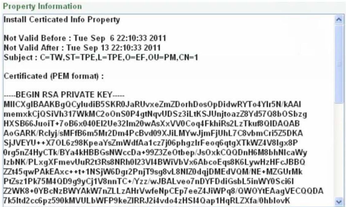
- To optionally create and install other certificates, remove the existing one by clicking the Remove button to erase the certificate.
- On the Web page, change the address from "http://" to https:// in the address bar and press Enter on the keyboard. Some Security Alert dialogs will pop up. Click OK or Yes to enable HTTPS.
Create Certificate Request
You can apply for an official certificate from an issuing Certificate Authority.
- Select Certificate Request and fill in the following information.
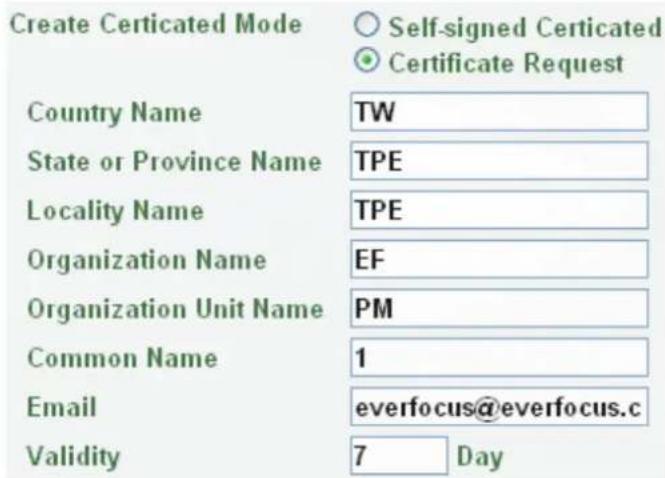
- Type the required Certificate information and then click the Apply button. The subject line will be displayed in the Created Request field
Created Request
C=TW,ST=TPE,L=TPE,O=EF,OU=PM,CN=1
Property
Remove
- Click the Property button, a pop-up window appears to display the details of the certificate.
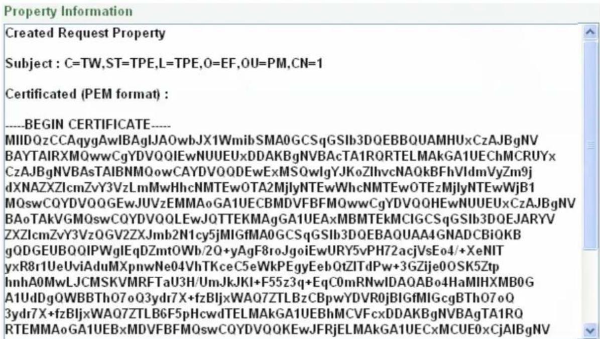
- To optionally create and install other certificates or request, remove the existing one by clicking the Remove button to erase the certificate or request.
- Copy the contents of the Certificate request (in PEM format) and paste it to the certificate request field on the Web page of the 3^rd -party certification authority such as Symantec VeriSign. Wait for the certificate authority to issue an SSL/TLS certificate and then download the issued certificate on your computer.
- In the Install Signed Certificated field, click the Browse button to search for the issued certificate, and then click the Upload button to import the certificate. Once the certificate has been uploaded, this field will show the subject line of the certificate.
7.1.2 Date / Time
You can set up the system's time on this page.
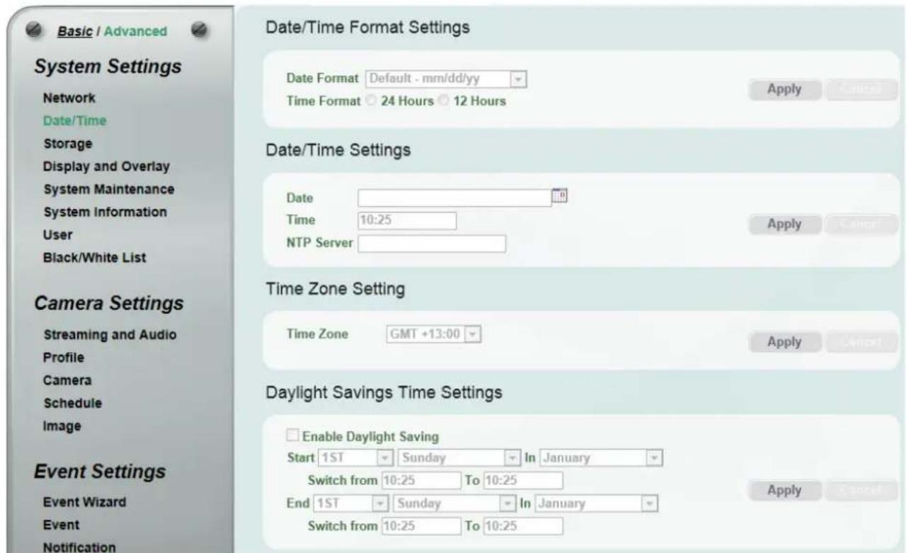
【Date/Time Format Settings】Select the desired Date / Time format and then click the Apply button. To enable displaying the date and time information on the Live View Window, you have to check the Date/Time box in the Overlay Text Settings (see 7.1.4 Display and Overlay).
【Date/Time Settings】
- Manual: Set the date/time if you won't be using an NTP server to update the date/time. Click Apply to save the setting.
■ NTP: Enter the Network Time Protocol server, if applicable. The camera's time will be automatically adjusted by synchronizing with the NTP server. Click Apply to save the setting.
【Time Zone Setting】Set the time zone of the camera's location. Click Apply to apply the changes or Cancel to cancel the changes and return to the previous settings.
【Daylight Savings Time Settings】Click Enable Daylight Saving to enable this schedule, and select the dates when the region's daylight saving period begins and ends. Click Apply to apply the changes or Cancel to cancel the changes and return to the previous settings.
7.1.3 Storage
You can configure the recording path / format, source video stream and SD card settings on this page.
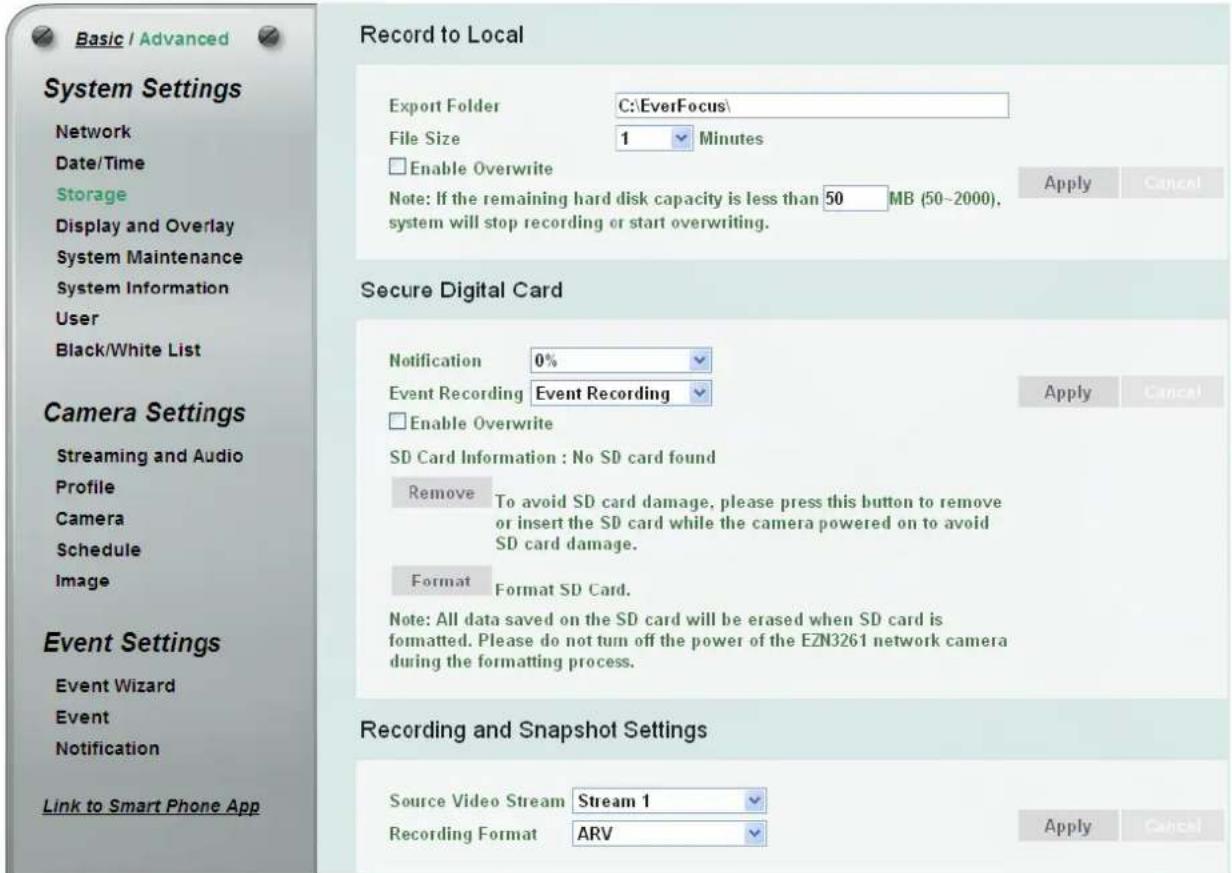
【Record to Local】This function can only be set up in the Advanced tab. You can configure the storage path for storing the live stream recordings / snapshot on your PC.
■ Export Folder: Type the storage path for storing the recordings / snapshot.
■ File Size: The user can limit the size of each recorded file here (in minutes). Once you click the Record button on the Live View window, the camera will start recording the live stream to your computer. When a single recording file exceeds the time you set, the system will create a new file to save that data to.
■ Enable Overwrite: Check the box for overwriting recording/snapshot file when the disk storage capacity is full. The user can set the storage capacity limitation in the in-sentence box below the Enable Overwrite setting: "If the remaining hard disk capacity is less than ____ MB (50\~2000),... "
Click Apply to apply the changes or Cancel to cancel the changes and return to the previous settings.
■ Notification: Select the percentage of storage space that should be left on the card before the camera notifies you of the impending storage shortage or overwrite.
■ Event Recording: Select the location where you want the camera to send the impending storage shortage text notification to.
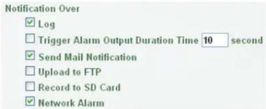
- FTP Back Up Only: Select to send the impending storage shortage text notification to the FTP server entered in the FTP Repository Settings (see 7.3.3 Notification).
- Event Recording: Select to send the impending storage shortage text notification to the checked locations in the Event Management (see 7.3.2 Event).
- Both: Select to send the impending storage shortage text notification to the FTP or the selected locations in the Event Management (see 7.3.2 Event).
■ Enable Overwrite: Check the box for overwriting files when the SD card is full.
■ SD Card Information: If an SD card has been inserted to the card slot of the camera, the SD card information will be displayed in this field.
■ Remove: Click before removing the card from the system (6.2.1 Inserting / Removing the SD Card).
■ Format: Click to format the card. All data saved on the SD card will be removed if the card is formatted (6.2.1 Inserting / Removing the SD Card).
Click Apply to apply the changes or Cancel to cancel the changes and return to the previous settings.
【Recording and Snapshot Settings】Select the desired video stream and recording format. The video stream can be configured in 7.2.1 Streaming and Audio. Click Apply to apply the changes or Cancel to cancel the changes and return to the previous settings.
7.1.4 Display and Overlay
You can configure the recording path / format, source video stream and SD card settings on this page.
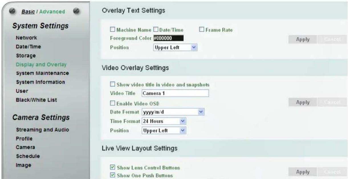
【Overlay Text Settings】Check the boxes to display the information on the Live View Window. The information will only be displayed on the Live View Window and will not be displayed on the live view video images nor snapshots. To change the foreground color of the text, directly click on the box and then select a color. Select a position where you want the information to be displayed on the Live Window. To change the Machine Name, see Machine Name in 7.1.5 System Maintenance. To change the day and time setting, see 7.1.2 Date / Time. Click Apply to apply the changes or Cancel to cancel the changes and return to the previous settings.
![Video Stream 1 View Size 640x480 English EZN3261 [ 10:05:00 03/11/2014 ] FPS:17/21 ZOOM x1.18 Digital Zoom One Push Focus Manual Control Trigger Event Reset Alarm Lens Control ++ + -- - + ++ + -- - - Focus Speed 4X](/content/2026/06/1186584/images/e97f47d87e02eba1b8e3bea14873660ccad4f7b9557b2b0ee3c22a8192a569bc.jpg)
【Video Overlay Settings】Check the boxes to enable displaying video title or date/time on the live view video images. Click Apply to apply the changes or Cancel to cancel the changes and return to the previous settings.
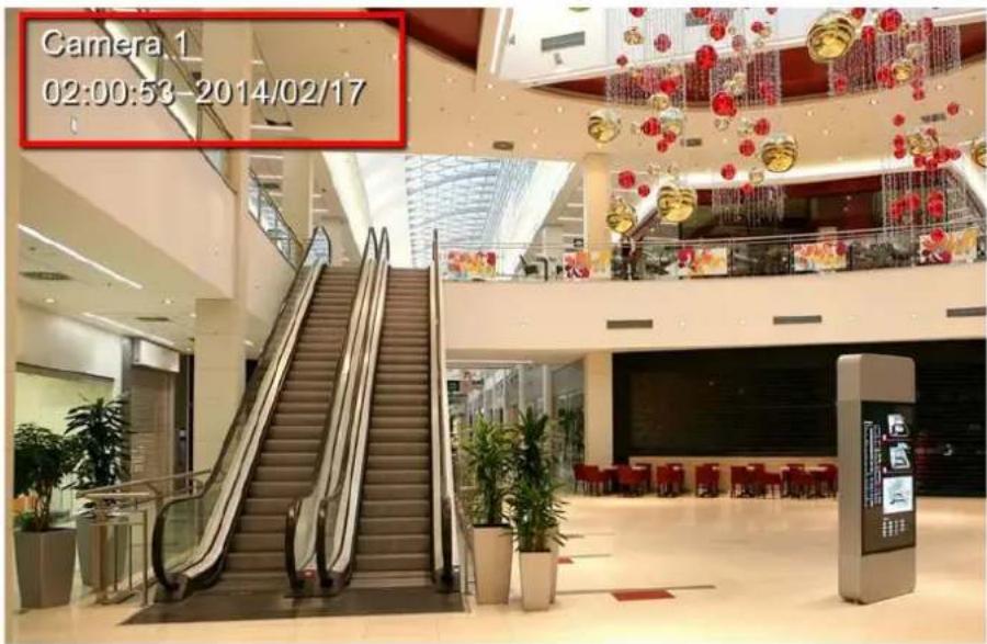
■ Show video title in video and snapshots: Check the box to enable displaying video title on the live view video images and snapshots. To change the title, type a name in the Video Title column.
■ Enable Video OSD: Check the box to enable displaying date/time information on the live view video images. Select the desired Date/Time format.
■ Position: Select a position where you want the video title or date/time information to be displayed on the live view video images.
【Live View Layout Settings】Check the box if you want to show the Lens Control buttons or One Push buttons on the Live View Window. Uncheck this box to hide the buttons. Click Apply to apply the changes or Cancel to cancel the changes and return to the previous settings.
7.1.5 System Maintenance
You can configure the recording path / format, source video stream and SD card settings on this page.
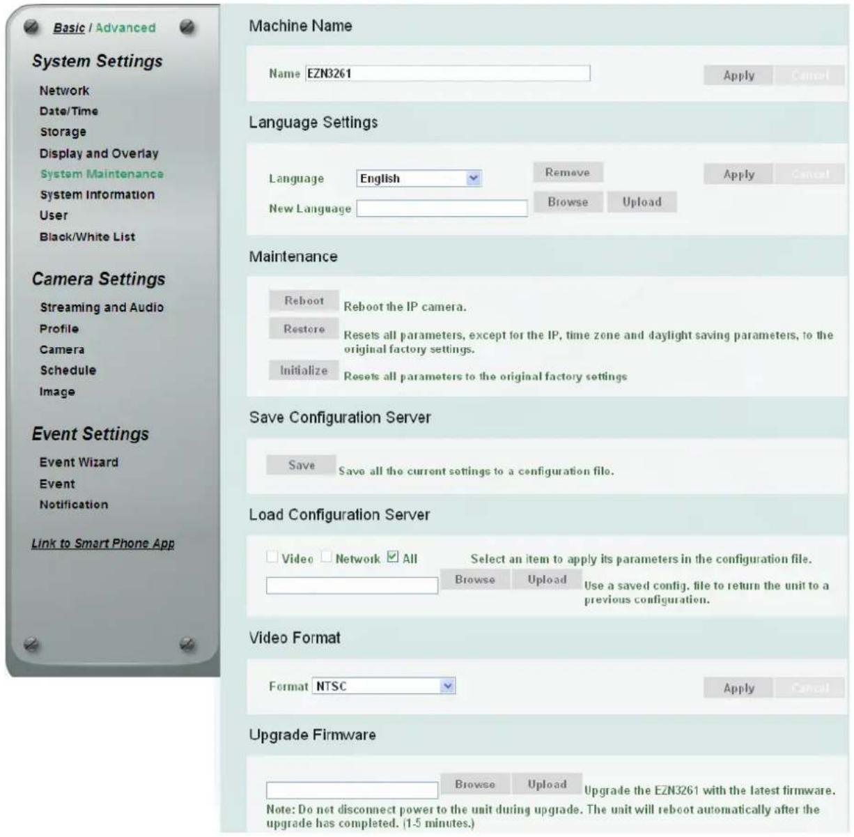
【Machine Name】If required, enter a new name for the machine. This name will be visible in the Machine Name field of the IP Utility software, which is included in the software CD. Click Apply to apply the changes or Cancel to cancel the changes and return to the previous settings.
【Language Settings】Select the language to be displayed on the Web interface of the IP camera. The default language is English.
To add a new language not listed in the current Language list, click the Browse button to locate the new language file (.evb) on your computer and then click the Upload button. Updated language files might be available on the manufacturer's website. Contact your vendor if required.
Click Apply to apply the changes or Cancel to cancel the changes and return to the previous settings.
Note: Uploading a new language file will cause the system to reboot automatically. Please create a new network connection to the IP camera when the reboot is complete.
【Maintenance】
■ Reboot: Click to reboot the unit without changing any of the settings. Use this function if the unit is not behaving as expected.
■ Restore: Click to restart and reset most of the current settings to their factory default values. The only settings that will not be changed to default are: IP Settings and DDNS Settings.
■ Initialize: This function can only be set up in the Advanced tab. This button should be used with caution. Clicking this button will return all of the camera's settings, including the IP address, to the factory default values. The camera will then have to be reconfigured.
Save: To make a backup file of the machine's current configurations, click this button to save all the configurations to a configuration file. This will enable the user to reload these configuration settings if the settings are changed and there is unexpected behavior.
Select Video to apply only the video parameters from the configuration file to the system. Select
Network to apply only the network parameters from the configuration file to the system. Select All to apply all the parameters from the configuration file to the system.
Browse: Click the Browse button to locate the saved config. File.
Load: Click the Load button to restore the system based on the selected parameters (Video, Network or All).
【Video Format】Select NTSC or PAL for your local scanning system. Click Apply to save the setting.
【Upgrade Firmware】This function can only be set up in the Advanced tab. Click the Browse button to find a previously prepared firmware upgrade file. Click the Upload button to install the new firmware.
Note:
- Do not disconnect power to the unit during the upgrade sequence. The unit will reboot automatically after the upgrade has completed (1-5 minutes).
- During the upgrade process, all event recording actions will be stopped. Event recording actions will resume after the camera is rebooted.
- If the "File Error, Please re-login!!" warning message appears when upgrading the firmware, please try the following instructions:
a. Go to Internet Explorer > Tools > Internet Option > Security > Custom.
b. Find and enable the Include local directory path when uploading files to a server.
7.1.6 System Information
You can see the system information and log information displayed on this page.
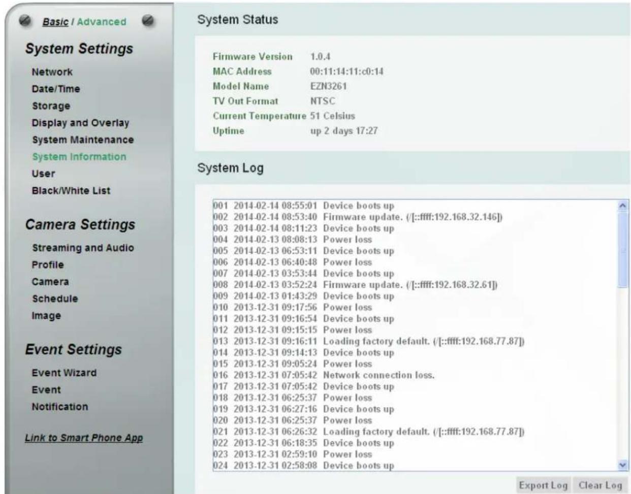
【System Status】Displayed the system information. The values cannot be changed on this page. The Uptime represents the period since the camera has been powered on. For example, up 21:28 represents the camera has been powered on for 21 hours and 28 minutes.
【System Log】Displayed the sequence number, date, time and event messages of the log event. The log will display the last 256 log events. Click the Export Log button to export the system log event list into a “.txt” file and select the location where the exported log file will be saved to. Click the Clear Log to erase all the log data from the camera. The system will be required to reboot after clicking the Clear Log button.
7.1.7 User
The system administrator can create up to ten user accounts on this page.
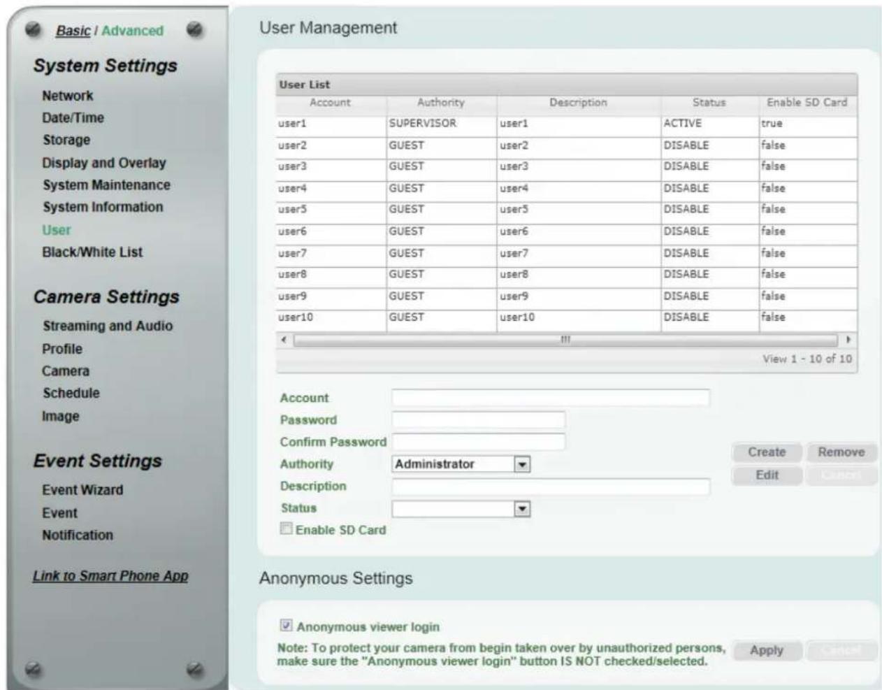
【User Management】The system has automatically created ten user accounts.
To set up an user account:
- Highlight a user account and its information will be displayed in the field below the account list.
- Revise the account name, password and description. Select an authority level for the user account.
- Supervisor / Administrator: The only difference between a supervisor and administrator is that a supervisor can edit an administrator's account and password, but an administrator cannot edit the supervisor's account and password. The supervisor and administrators all have unrestricted access to the Setting submenus and can determine the registration of all other users.
- User: A user can not only view the live view but also view/configure the below camera settings.
| View Configure | |
| System Settings | |
| Network Network >Protocol Settings | |
| Date/Time | Date/Time > Date/Time Format Settings |
| Storage > Record to Local Storage > Record to Local | Local |
| Display and Overlay > Overlay Text Settings | Display and Overlay > Overlay Text Settings |
| Display and Overlay > Video Overlay Time Stamp Settings | Display and Overlay > Video Overlay Time Stamp Settings |
| System Maintenance > Language Settings | System Maintenance > Language Settings |
| System Information System Information > Export Log | |
| Camera Settings | |
| Streaming and Audio - | |
| Camera - | |
| Schedule - | |
| Image - | |
• Guest: The lowest level of access, which only allows the user access to the live view page.
- Select Active or Disable to active or disable the user account.
- Check the Enable SD Card box to allow the user to access the SD card playback function.
- Click the Edit button to save the changes.
Create
Create: The button is only activated when the number of list is less than ten. Enter the account information and click the Create button, the new account will be listed in the account list.
Remove
Remove
Edit
Click the Edit button and the account will be edited.
Cancel
【Anonymous Settings】Check the box to allow the unauthorized persons to log in the camera. Click Apply to apply the changes or Cancel to cancel the changes and return to the previous settings.
7.1.8 Black/White List
Use this page to specify IP addresses that are allowed / denied to access this camera. By default, any IP address can access the camera.
Note: The Allowed IP addresses only become relevant when the Denied items contain a Network or Range, and the supervisor wants to allow one or more IP addresses within that excluded range or network. In such a scenario, the user would enter the excluded range or network for the Denied items, and enter the exceptions for the Allowed items.
Black/White Management
| Permiss | Mask | IPv4 Address | IPv4 From | IPv4 End | IPv6 Address | IPv6 From | IPv6 Er |
| deny | 192.168.12.170 | 192.168.12.180 | |||||
| allow | 192.168.12.175 | 192.168.12.175 |
IP Type
Permission Type
Rule
IP Address From
IPv4
Allow
Single
......
Create
Edit
Remove
Cancel
■ IP Type: Select IPv4 or IPv6 from the drop-down list.
- Permission Type: Select Deny to deny the IP addresses configured below from accessing the camera. The Allow option is only relevant if you’ve set up at least one Deny item configured with Network or Range network rule from the Rule drop-down list.
■ Rule: Select a network rule and then fill in the IP information in the below boxes.
■ Single: Type a single IP address in the IP Address field below.
■ Network: Type the IP address and subnet mask in the field below.
■ Range: Type a range for the IP addresses.
Create : Set up the IP information and click the Create button, the created IP information will be listed in the Black/White list.
Remove : Highlight an item in the list and then click the Remove button to remove the highlighted item.
Edit: Highlight an item in the list and set up the IP information in the boxes below the Black/White list. Click the Edit button and the item will be edited.
Cancel : Click the button to cancel the changes and return to the previous settings.
7.2 Camera Settings
You can configure camera related settings, such as video / audio, region of interest and privacy mask.
7.2.1 Streaming and Audio
Region of Interest Settings
natural_image
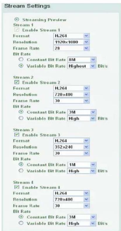
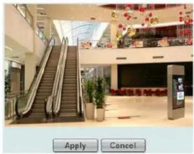
Interior view of a modern multi-level shopping mall with escalators and seating (no visible text or signage)【Stream Settings】This IP camera can output three video streams simultaneously. For each of these streams, the user can set the compression format, resolution, bit rate, and frame rate individually. Stream 1 is always enabled for live view. To enable Stream 2, Stream3 and/or Stream 4, check the Enable Stream 2 / Enable Stream 3 / Enable Stream 4 box.
Note: If you connect to the camera via the Internet and experience a delay (lag time) in the video feed, try to reduce the number of streams and the quality and resolution of the streams – but keep the frame rate at its maximum.
Format: Select the encoding format – H.264, MJPEG or MPEG4.
Resolution: Select the most suitable resolution for your needs.
Frame Rate: This function can only be set up in the Advanced tab. Select from 1 to 30 fps.
Bit Rate: This function can only be set up in the Advanced tab. If required, select whether you want the stream to stream a Constant Bit Rate or a Variable Bit Rate, and set the values of whichever option you choose.
Click Apply to apply the changes or Cancel to cancel the changes and return to the previous settings.
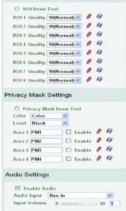
【Region of Interest Settings】This function can only be set up in the Advanced tab. The Region of Interest (ROI) function allows users to set up multiple regions within an image with better quality and less distortion than the rest of the image. You can also use this function together with the Digital Zoom function on the Live View window to get a better image result. Up to eight ROIs can be configured in this field.
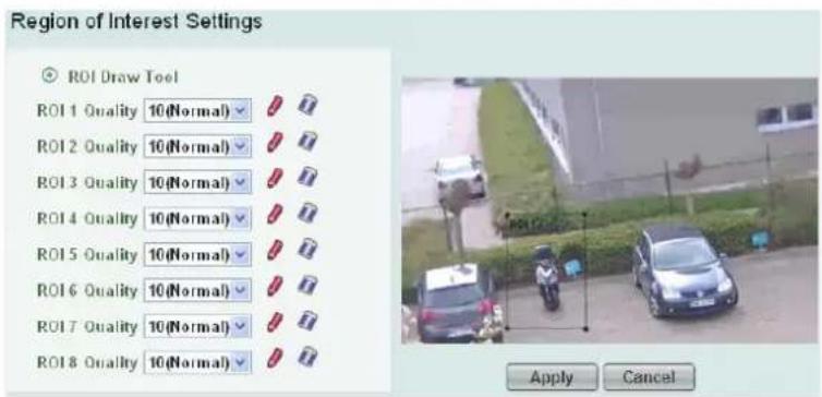
To set up an ROI region:
- Enabled the ROI Draw Tool and click the Draw button
- On the left-side live image, move the cursor to the position where you want the ROI rectangle to start and then click. Move the cursor to the position (diagonally opposing corner) where you want the ROI rectangle to end and then click.
- Select a quality value for the ROI from the Quality drop-down list.
- Click the Apply button to apply the settings, or click the Cancel button to reset without saving the settings.
【Privacy Mask Settings】This function can only be set up in the Advanced tab. The Privacy Mask can block out sensitive areas from view, covering the areas with colored or black and white boxes in both live view and recorded clips. This feature is useful when users' don't want the sensitive information visible. Up to four Privacy Masks can be configured.
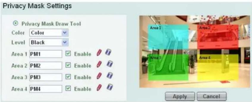
To set up a Privacy Mask:
- Enabled the Privacy Mask Draw Tool.
- From the Color drop-down list, select Color to make the masks appear as colored rectangles on the screen; or select B/W to make the masks appear as gray rectangles on the screen.
- Select a color if you select Color from the color drop-down list. Select a level of grayness if you select B/W from the color drop-down list.
- Check the Enable box to enable the configured privacy mask.
- Click the Draw button and move the cursor on the left-side live image.
- Move the cursor to the position where you want the mask rectangle to start and then click. Move the cursor to the position (diagonally opposing corner) where you want the mask rectangle to end and then click.
- Click the Apply button to apply the settings, or click the Cancel button to reset without saving the settings.
【Audio Settings】The camera can transmit audio to your computer if you have connected an external microphone / line-in (TRS) audio device to its audio Input. Check the Enable Audio box to enable the camera's audio input function. Select an audio input type from the Audio Input drop-down list and then adjust the audio input volume. Note that the camera provides a line-in 3.5mm jack (TRS), therefore, TRS microphones with a (built-in) amplifier and external power supply are required.
Click Apply to apply the changes or Cancel to cancel the changes and return to the previous settings.
7.2.2 Profile
The Profile Settings is designed with four camera modes, which can be applied in various scenes to enhance image quality. You can apply different camera modes to the daytime and nighttime.
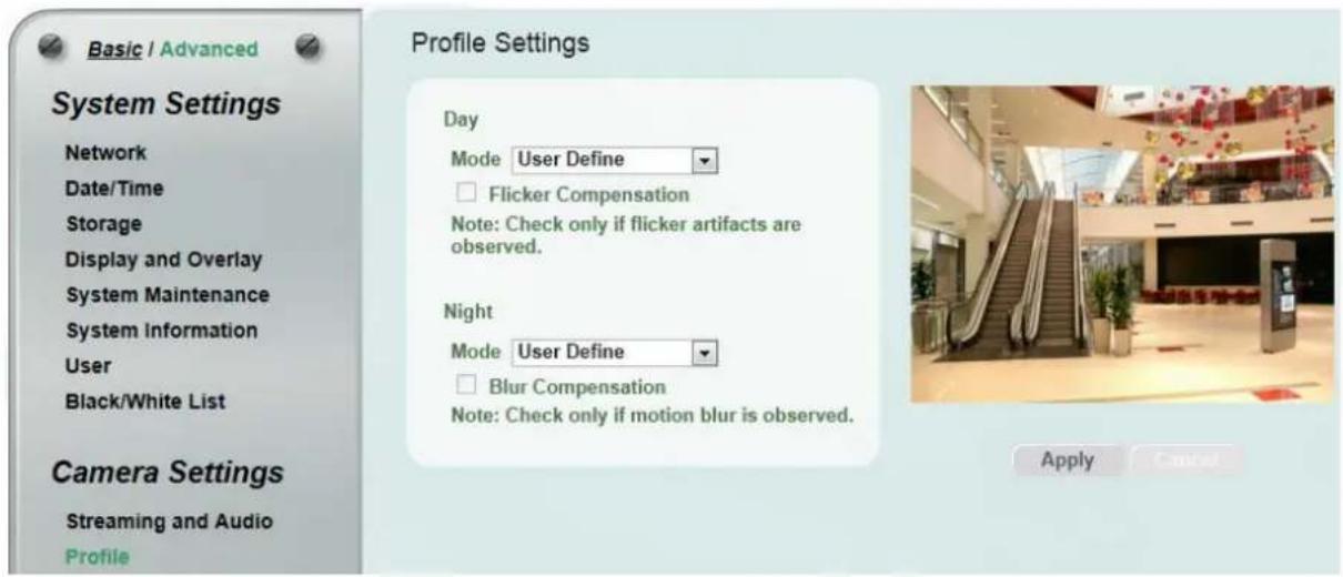
【Day Mode】Select a camera mode and then click the Apply button to save the settings.
■ Vivid: Select Vivid mode to have images with optimized contrast ratio. You can further configure the camera settings on the Camera setup page if required. Note that selecting the Vivid mode will lock (grayed-out) some Camera Settings on the Camera setup page such as Exposure Settings (AE), Noise Reduction Settings and Monitor Settings.
■ Standard: Select Standard mode to have images with system configured settings. You can further configure the camera settings on the Camera setup page if required. Note that selecting the Standard mode will lock (grayed-out) some Camera Settings on the Camera setup page such as Exposure Settings (AE), Noise Reduction Settings and Monitor Settings.
■ More Detail: Select More Detail mode to enhance the dark parts of the images. You can further configure the camera settings on the Camera setup page if required. Note that selecting the More Detail mode will lock (grayed-out) some Camera Settings on the Camera setup page such as Exposure Settings (AE), Noise Reduction Settings and Monitor Settings.
■ User Define: Select User Define mode to customize the camera settings. You can configure all the camera settings on the Camera setup page.
Flicker Compensation: Check the box to enable the Flicker Compensation function. Please enable this function only if flicker artifacts are observed.
【Night Mode】Select a camera mode and then click the Apply button to save the settings.
■ High Contrast: Select High Contrast mode to have images with higher contrast ratio. You can further configure the camera settings on the Camera setup page if required. Note that selecting the High Contrast mode will lock (grayed-out) some Camera Settings on the Camera setup page such as Exposure Settings (AE), Noise Reduction Settings and Monitor Settings.
■ Standard: Select Standard mode to have images with system configured settings. You can further configure the camera settings on the Camera setup page if required. Note that selecting the Standard mode will lock (grayed-out) some Camera Settings on the Camera setup page such as Exposure Settings (AE), Noise Reduction Settings and Monitor Settings.
■ More Detail: Select More Detail mode to enhance the dark parts of the images. You can further configure the camera settings on the Camera setup page if required. Note that selecting the More Detail mode will lock (grayed-out) some Camera Settings on the Camera setup page such as Exposure Settings (AE), Noise Reduction Settings and Monitor Settings.
■ User Define: Select User Define mode to customize the camera settings. You can configure all the camera settings on the Camera setup page.
Blur Compensation: Check the box to enable the Blur Compensation function. Please enable this function only if motion blur is observed.
7.2.3 Camera
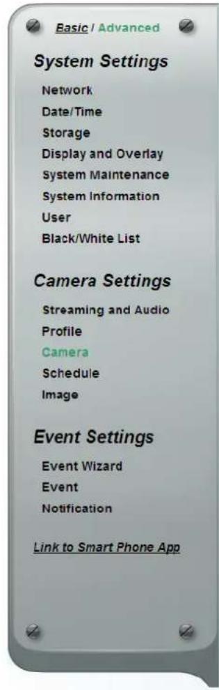
Day/Night Settings
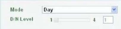
Day Profile Night Profile
Lens Settings

Exposure Settings
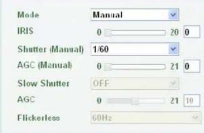
Backlight Compensation Settings

Features
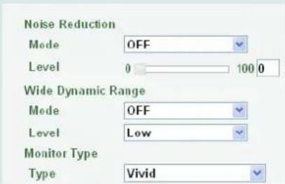
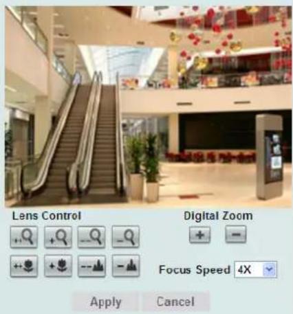
■ Mode: Select a mode from the drop-down list.
- Auto: Select to let the camera automatically switch to Night mode (black and white images with IR LED on) when the light levels fall to a specified level, and back to Day mode (color images) when the light levels rise to a specified level.
• Day: Select to keep the camera in Day mode (color images with IR LED off), even in nighttime. - Night: Select to keep the camera in Night mode (black and white images with IR LED on), even in daytime.
- Schedule: Select to let the camera to switch to Day mode or Night mode (IR LED on) based on the day and night schedule settings (see 7.2.4 Schedule).
-
Auto mode without IR LED: Select to let the camera automatically switch to Night mode (black and white images with IR LED off) when the light levels fall to a specified level, and back to Day mode (color) when the light levels rise to a specified level.
-
Night mode without IR LED: Select to keep the camera in Night mode (black and white images with IR LED off), even in daytime.
- Schedule without IR LED: Select to let the camera to switch to Day mode or Night mode (IR LED off) based on the day and night schedule settings (see 7.2.4 Schedule).
■ D/N Level: This function can only be activated if you select Auto / Auto mode without IR LED mode in the Day/Night Settings field. Adjust the level (1-4 lux) for the camera to switch from Day mode to Night mode based on the light level detected by the Light Sensor. The camera will switch back from Night mode to Day mode when the detected light level has reached 2-level higher than the level you have set up.
For example:
If you set up the D/N level to 1 (lux), the camera will automatically switch from:
• Day to Night when the light level is below 1 lux.
• Night to Day when the light level has reached 3 lux.
If you set up the D/N level to 2 (lux), the camera will automatically switch from:
• Day to Night when the light level is below 2 lux.
• Night to Day when the light level has reached 4 lux.
Click Apply to apply the changes or Cancel to cancel the changes and return to the previous settings.
Day Profile/ Night Profile: Select Day Profile to configure the following settings for daytime and select Night Profile to configure the following settings for nighttime. Click the Apply button to save the settings.
Note: Some settings in the Exposure Settings / Features may be grayed-out. To configure all the settings, select User Define from the Day Mode / Night Mode drop-down list (see 7.2.2 Profile).
【Lens Settings】Click Apply to apply the changes or Cancel to cancel the changes and return to the previous settings.
■ Focus Mode: Select Manual to manually adjust the focus or select Auto to enable the Focus button on the live view window (see 5.4 Live View Window). Note that if you select Auto, the camera will automatically adjust focus every time when you click the zoom in/out button on the Live View window or push the 5-Axis Button to zoom (see 3.2 5-Axis Button).
【Exposure Settings】This function can only be set up in the Advanced tab and can only be activated when you select User Define from the Day Mode / Night Mode drop-down list (see 7.2.2 Profile). This setting is used to adapt to the amount or type of light used by the camera. Click Apply to apply the changes or Cancel to cancel the changes and return to the previous settings.
■ Mode: Select a mode from the drop-down list.
- Auto: Selecting Auto for the camera to automatically adjust the Shutter based on the measured light level.
- ALC (Shutter Priority): Selecting ALC (Automatic Light Control) allows the camera circuitry to either take bright spots more into consideration (peak), bringing out detail in bright areas, or less into consideration (average) bringing out detail in shadows.
-
Manual: Select this option to manually set up the IRIS, Shutter (Manual) and AGC (Manual) values.
-
IRIS: This function is only activated if you select Manual in the Mode field.
■ Shutter (Manual): The function is only activated if you select ALC or Manual in the Mode field. If enabled, this setting lets you set the shutter speed yourself (measured in fractions of a second).
■ AGC (Manual): The function is only activated if you select Manual in the Mode field. Set the Auto Gain Control limit here. The lower the AGC level, the lower the video signal and the noise.
■ Slow Shutter: The function is only activated if you select Auto in the Mode field.
■ AGC: The function is only activated if you select Auto or ALC in the Mode field. Set the Auto Gain Control limit here. The lower the AGC level, the lower the video signal and the noise.
■ Flickerless: The function is only activated if you select Auto in the Mode field. Choose between OFF, 50HZ, 60HZ, 50HZ (High Luminance) or 60HZ (High Luminance).
【Backlight Compensation Settings】The Backlight Compensation (BLC) function is useful when the background of the subject is very bright and the subject itself is dark. Click Apply to apply the changes or Cancel to cancel the changes and return to the previous settings.
BLC Edit Mode: Click the Enable button, the BLC grids appear on the image. Click on the grids to enable / disable the BLC function. The selected grids (in green) will be applied with the BLC function.
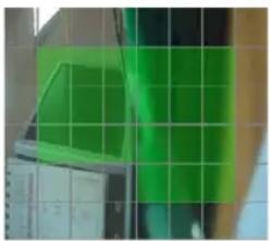
natural_image
Green-tinted abstract pattern with grid overlay, no visible text or symbols【Features】This function can only be set up in the Advanced tab. Click Apply to apply the changes or Cancel to cancel the changes and return to the previous settings.
- Noise Reduction (NR): This limits the amount of digital “video noise” that is usually found in any video stream, and helps to reduce file size. Select ON / OFF to enable / disable the Noise Reduction function. Slide the Level bar to set up the level. The higher the level, the more the reduction. Note that this function can only be activated when you select User Define from the Day Mode / Night Mode drop-down list (see 7.2.2 Profile).
■ Wide Dynamic Range (WDR): The WDR function provides clearer images when both of the very bright and dark areas simultaneously appear on the camera view. There are three value options: OFF, ON and Auto. Note that when WDR is ON, some parts of the image may appear solarized. This is normal for WDR, and is not a camera malfunction.
■ Monitor Type: Users can use this field to optimize video quality of the monitor. Note that this function can only be activated when you select User Define from the Day Mode / Night Mode drop-down list (see 7.2.2 Profile).
7.2.4 Schedule
The Schedule setup page is designed for users to configure the daytime and nighttime of each day. The Schedule setting is only functional if you select Schedule from the D/N Mode drop-down list on the Camera setup page.
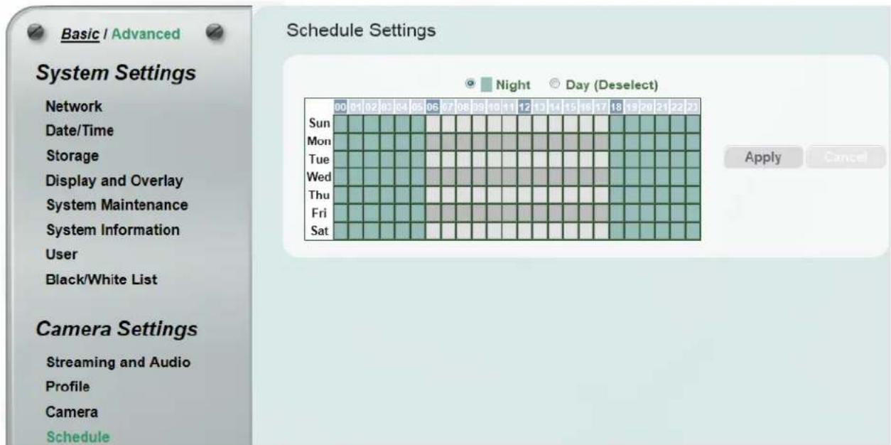
Select Night and then move the cursor on the desired time square, click and drag the cursor over the time squares to configure them to the Night mode (green color). Select Day and then move the cursor on the desired time square, click on the time squares to configure them to the Day mode (gray color).
Click Apply to apply the changes or Cancel to cancel the changes and return to the previous settings.
7.2.5 Image
This function can only be set up in the Advanced tab.
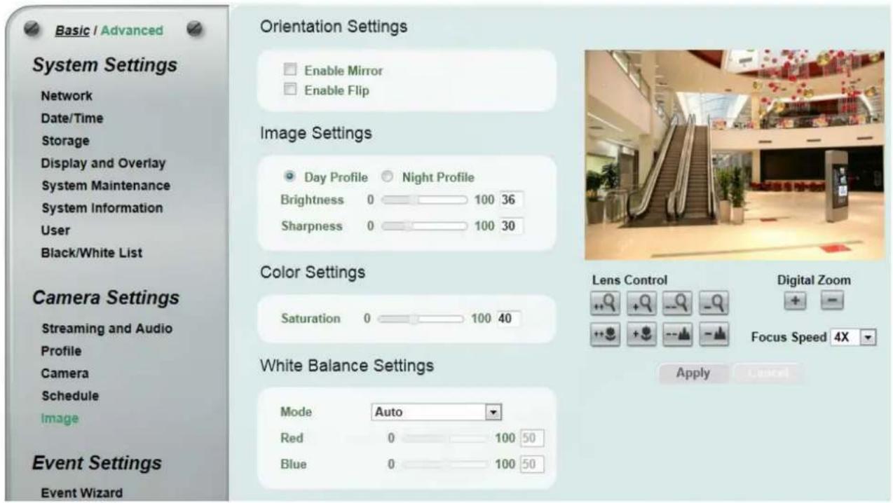
【Orientation Settings】
■ Enable Mirror: Check the box to enable the mirror function. The image will be rotated horizontally around a vertical axis.
■ Enable Flip: Check the box to enable the flip function. The image will be rotated vertically around a horizontal axis.
【Image Settings】Select Day or Night and then adjust the slide bars below to configure the brightness and sharpness for daytime or nighttime.
【Color Settings】Slide the bar to adjust the saturation.
【White Balance Settings】Select a mode that delivers the best image quality for the camera's light environment.
■ Auto: Select to let the camera automatically adjust the White Balance. In the Auto mode the camera computes the white balance value output using color information from the entire screen. It outputs the proper value using the color temperature radiating from a black subject based on a range of value from 3000 to 7500K.
■ Manual: Select to adjust the Red and Blue values yourself in the fields below this field.
7.3 Event Settings
You can set up the Motion Detection event or Tampering Detection event to automatically notify the users when an event occurs. You can also set up a schedule to automatically record the videos when an event occurs.
7.3.1 Event Wizard
The Event Wizard allows users to easily configure the event settings. Follow the on-screen instructions to complete the event settings.
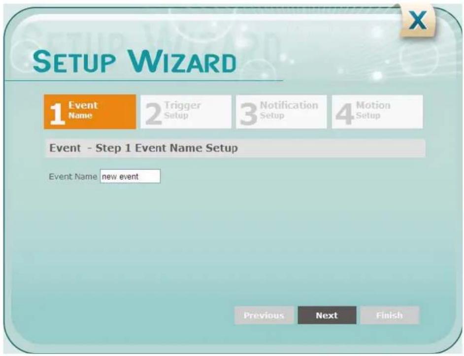
7.3.2 Event
This function can only be set up in the Advanced tab. Except the Event Wizard, you can also configure the event settings along with the Recording Schedule on this page.

Basic / Advanced

System Settings
Network
Date/Time
Storage
Display and Overlay
System Maintenance
System Information
User
Black/White List
Camera Settings
Streaming and Audio
Camera
Schedule
Image
Event Settings
Event Wizard
Event
Notification
Link to Smart Phone App


Event Management
| Event List | |||
| Name | Type | Notification | Enable |
| new event | VND | email,FTP,syslog | true |
| View 1 - 1 of 1 | |||

√ Enable This event
□ Enable Re-trigger miniman interval between triggers 10 second
Enable Pre-trigger Buffer
√ Enable Post-trigger Buffer
Notification Over
Log
√ Send Mail Notification
Upload to FTP
□ Record to SD Card
□ Network Alarm
Event Trigger Settings

Trigger Options Settings

Schedule Settings
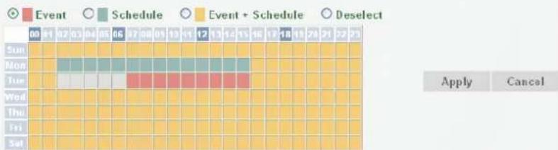
Motion Settings
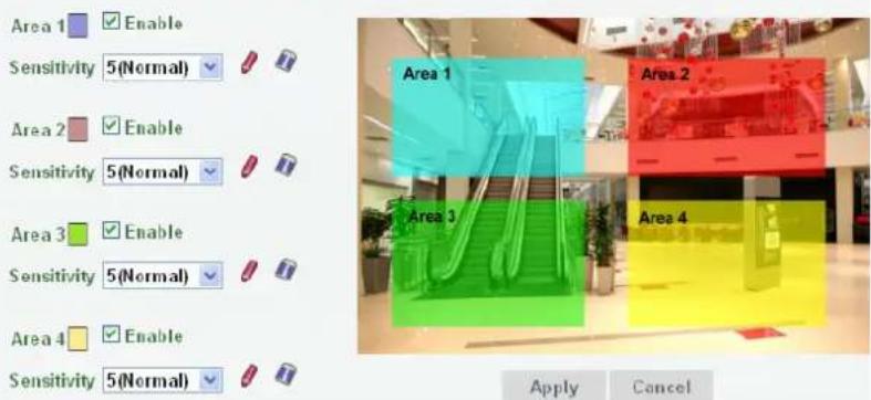
【Event Management】You can set up the events such as Motion Detection or Tampering Detection to automatically notify the users when an event occurs.
Event Name: Type an event name.
■ Event Trigger Type: Select an event for the to-be-specified-below reaction/s.
- Alarm Input: Select this if you want a reaction trigger coming from any external, connected sensor to activate a to-be-specified-below reaction/s via the camera system. Make sure that a suitable device is actually connected to the alarm input relay.
- Manual Trigger: Select this option if you want to manually trigger the alarm by clicking the Trigger Event button on the Live View Page.
- Motion Detection: Select this option to trigger the to-be-specified-below reaction/s when motion events occur. You have to pre-configure the Motion Settings for this function to work.
- Schedule Recording: Select this option if you want the Schedule Recording periods configured in the Schedule Settings to activate this event. In this scenario, a preconfigured event reaction like a log entry will list the start and end times of each period. Actual recording will only be triggered if the event is preconfigured to do so.
- Tampering Detection: Select this option if you want the camera's tampering detection sensor to trigger the to-be-specified-below reaction/s. You can set up the tamper duration time in the Event Trigger Settings field below.
■ Enable This Event: Check the box to activate the event.
■ Enable Re-trigger minimum interval between triggers xx second: Check the box to set a minimum time after the event is triggered before the event can be triggered again.
■ Enable Pre-trigger Buffer: Check the box if you want the Event reaction (as selected in the "Notification Over" field below) to be the activation of the video recording function, and if you want the recording to include the video feed from the time period (configurable in the Schedule Settings field) just before the Event trigger occurred.
■ Enable Post-trigger Buffer: Check the box if you want the Event reaction (as selected in the Notification Over field) to be the activation of the video recording function, and if you want the recording to include the video feed from a time period (configurable in the Schedule Settings field) just after the Event trigger occurred.
Notification Over: Select the desired notification types from the following items.
- Log: Check the box if you want the camera to list the event's details in its log if the event is triggered.
■ Trigger Alarm Output: Check if you want the camera to relay the event reaction to a device attached to the alarm relay output wire and then set up the alarm output duration time.
■ Send Mail Notification: Check the box if you want the camera to send an email text notification and one image file to the email address entered in the SMTP Settings field (see 7.3.3 Notification).
■ Upload to FTP: Check the box if you want the camera to upload the recordings to the FTP server entered in the FTP Repository Settings (see 7.3.3 Notification).
■ Record to SD Card: Check the box if you want the camera to start recording its video feed (when the event occurs) on an on-camera SD Card (if such a card has been inserted).
Note: The recording will only be as long as the combined Pre- and Post-trigger Buffers, so make sure you enable at least one of these buffers, especially the Post-trigger Buffer.
■ Network Alarm: Check the box if you want the camera to send a network alarm signal (when the event occurs) to the CMS servers. Note that you have to configure the Network Alarm Settings for this function to work (see 7.3.3 Notification).
Create : Set up the Event information and click the Create button, the created Event information will be listed in the Event List.
Remove: Highlight an item in the Event List and then click the Remove button to remove the highlighted item.
Edit : Highlight an item in the Event List and edit the Event information on the left-side. Click the Edit button and the item will be edited.
Cancel : Click the button to cancel the changes and return to the previous settings.
■ Input 1 Trigger Type: Select Normal Open or Normal Close from the drop-down list.
■ Output 1 Contact Type: Select Normal Open or Normal Close from the drop-down list.
- Tamper Duration Time: Set up a duration time between 10 and 120 seconds. When a tampering event has been detected and the duration reached the setup time, the camera will trigger the event.
【Trigger Options Settings】
■ Pre-trigger Buffer: Select the duration for the buffer. This will determine the amount of footage (length of time) before the event trigger moment that will be included in an event-triggered video recording, if that buffer and video recording has been enabled in the Event Management field.
√ Enable Pre-trigger Buffer
■ Post-trigger Buffer: Select the duration for the buffer. This will determine the amount of footage (length of time) after the event trigger moment that will be included in an event-triggered video recording, if that buffer and video recording has been enabled in the Event Management field.
√ Enable Post-trigger Buffer
Click Apply to apply the changes or Cancel to cancel the changes and return to the previous settings.
【Schedule Settings】Users can configure the recording schedule here. Select the desired recording types among the options below. Click and drag the cursor on the time block, which will be applied with the selected recording type.
■ Event Recording (Red): Select for the camera to activate all the Event Recording set up in the Event Management field (Event Trigger Type), except the Schedule Recording.
■ Schedule Recording (Green): Select for the camera to activate only the Schedule Recording set up in the Event Management field (Event Trigger Type).
■ Event + Schedule (Yellow): Select for the camera to active both of the configured Event and Schedule Recordings.
■ Deselect (Grey): Select for the camera to stop recording.
Click Apply to apply the changes or Cancel to cancel the changes and return to the previous settings.
【Motion Settings】Use this page to configure up to four areas in which motion will be detected.
When a motion is detected by the camera, the motion detection icon will appear at the top right corner on the Live page to alert the user. This function can also be linked with correctly configured Events to trigger Event reactions like the activation of video recording periods, snapshots, etc.
To set up the Motion area:
-
Check the Enable box to enable the selected area.
-
Select a sensitivity value of the motion detection sensor function.
-
Click the Draw button and move the cursor on the left-side live image.
-
Move the cursor to the position where you want the motion rectangle to start and then click. Move the cursor to the position (diagonally opposing corner) where you want the motion rectangle to end and then click.
-
Click the Apply button to apply the settings, or click the Cancel button to reset without saving the settings.
7.3.3 Notification
This function can only be set up in the Advanced tab.
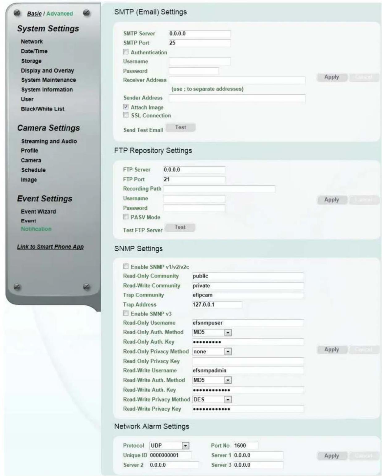
【SMTP (Email) Settings】This area is for configuring the mail server that is used to send e-mail text notifications and one image file from the camera to predefined addresses via SMTP. Note that to enable e-mail notification function, you have to check the Send Mail Notification box in the Event Management field (see 7.3.2 Event).
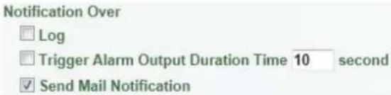
■ SMTP Server: Enter the IP address or the host name of the SMTP server used to send e-mails.
■ SMTP Port: Enter the port number for SMTP. The default is 25.
■ Authentication: Check the box if the SMTP server requires authentication (user/password).
- Username: Input the user's login ID if the SMTP server requires authentication.
- Password: Input the user's login password if the SMTP server requires authentication.
- Receiver Address: Input the e-mail addresses for receiving an e-mail message when events occur. Please use “;” to separate multiple addresses.
- Sender Address: Input the sender's e-mail address, so that the receiver can recognize the sender when an event message is received.
- Attach Image: Check the box if you want to attach an image when events occur.
- SSL Connection: Check the box to enable the SSL function. Enable this function means you can access the camera through the SSL protocol that provides communication security over the Internet.
■ Send Test Email: Click the Test button to send a testing email to the assigned address.
Click Apply to apply the changes or Cancel to cancel the changes and return to the previous settings.
【FTP Repository Settings】This area is for configuring the FTP server that is used to send alarm recordings from the camera to the preconfigured FTP server. Note that to enable uploading recordings to the FTP server function, you have to check the Upload to FTP box in the Event Management field (see 7.3.2 Event).
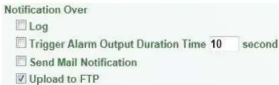
■ FTP Server: Enter the IP address or the host name of the FTP server.
■ FTP Port: Enter the port number for the FTP server. Default is 21.
■ Recording Path: Assign the recording path.
■ Username: Set FTP User's name.
■ Password: Set FTP password.
■ PASV mode: Check the box to enable Passive mode. Passive mode is normally enabled. If a connection cannot be established, uncheck "PASV Mode".
■ Test FTP Server: Click the Test button to send a testing file to the assigned FTP server.
Click Apply to apply the changes or Cancel to cancel the changes and return to the previous settings.
【SNMP Settings】The default values for SNMP v1/v2/v2c and SNMP v3 are already filled in. Click either of the Enable buttons to enable either of the two. Make your changes as desired. Click on the Trap Address field to enter the digits, if required.
Click Apply to apply the changes or Cancel to cancel the changes and return to the previous settings.
【Network Alarm Settings】This function works with EverFocus CMS software. The camera can send a network alarm signal (when the event occurs) to the CMS servers. To establish the connection between the camera and CMS servers, the protocol and port number should match with each other. For more details, please refer to the CMS user's manual. Note that to enable the Network Alarm function, you have to check the Network Alarm box in the Event Management field (see 7.3.2
Event).
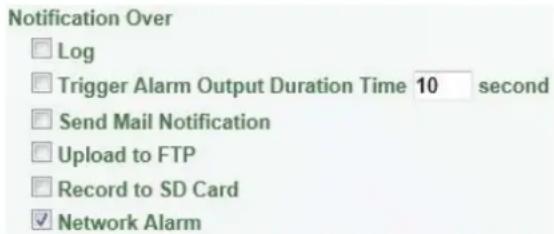
Click Apply to apply the changes or Cancel to cancel the changes and return to the previous settings.
7.4 Link to Smart Phone App
You can access camera live view or take a snapshot via your smart phone. This page is designed for users to download the mobile app to your mobile phone by scanning the QR code.
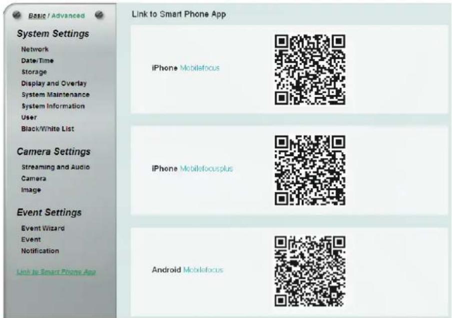
MobileFocus
for iPhone
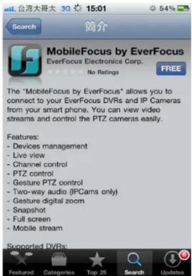
MobileFocusPlus
for iPhone
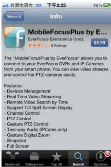
MobileFocus
for Android-based smart phone
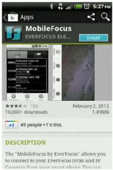
8. Upgrading Firmware Using IP Utility
You can upgrade the Firmware using the IP Utility software included in the software CD.
- Install and then start the IPU program, the following IPU window appears. The IPU will automatically search the IP devices connected in the LAN.
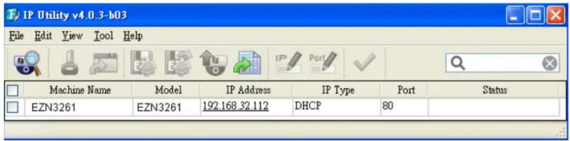
- Log in the camera by checking the desired model and then click the Log in icon. The Log in dialog box appears.
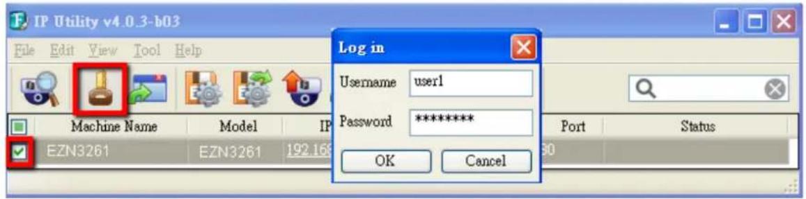
- Type the Username and Password. Click the OK button, the Login status displays.
| Machine Name | Model | IP Address | IP Type | Port | Status |
| EZN3261 | EZN3261 | 192.168.32.112 | DHCP | 80 | Login |
Note:
- The default user ID is user1 and the default password is 11111111.
- If you select more than one camera that has the same user ID / password, you will be able to log in several cameras at once.
-
Up to 10 cameras can be simultaneously upgraded to the latest firmware. If you connect the cameras to a PoE switch, please make sure the Power Consumption of the PoE switch is sufficient.
-
Click the Upgrade Firmware button , a browsing window appears.
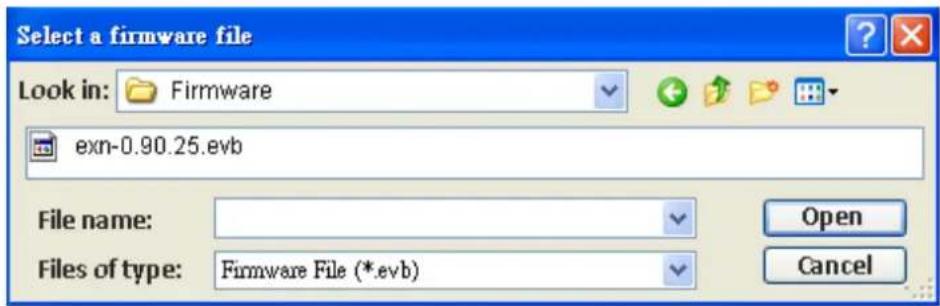
- Select the firmware file (.evb) and then click Open. The IPU will automatically upgrade the firmware. The camera will reboot once the upgrade process is complete.
| Machine Name | Model | IP Address | IP Type | Port | Status |
| EZN3261 | EZN3261 | 192.168.32.112 | DHCP | 80 | Success |
- Specifications
| Model EZN3261 EZN3361 | |||
| Camera | |||
| Image Sensor | 1/3" CMOS Sensor | ||
| Megapixel | 2 MP | 3 MP | |
| Min. Illumination | Color: 0.5 lux at F1.8B/W: 0.095 lux at F1.80 lux at F1.8 (IR LEDs on) | ||
| Electronic Shutter | 8 ~ 1/15,000 sec. | ||
| Scanning System | NTSC / PAL | ||
| WDR | Yes | ||
| BLC Yes | |||
| Optical Zoom 10x | |||
| Digital Zoom 10x | |||
| Image Setting | Compression, Brightness, Sharpness, Saturation, White Balance, Exposure Control, Rotation, Mirroring of Images, Text and Image Overlay, Auto Gain Control, Digital Noise Reduction, Auto White Balance, Hallway Display (9:16) | ||
| Event Trigger | Manual Trigger, Motion Detection, Tamper Detection | ||
| Notification | Send mail notification, upload video to FTP, record video to PC and Network alarm | ||
| Lens | |||
| Iris | DC Iris | ||
| Focal Lens | 4.9 ~ 49 mm, 10x optical zoom lens | ||
| Aperture Ratio | F1.8 ~ 360C | ||
| True Day / Night | Yes (with removable IR-cut filter) | ||
| Angle of View | Horizontal | Wide 100° / Tele 273° | |
| Vertical | Wide 73.3° / Tele 20.4° | ||
| Diagonal | Wide 129.1° / Tele 34.3° | ||
| IR Distance | 40 m / 131 ft | ||
| IR LED Quantity | 12 | ||
| Video | |||
| Video Compression | H.264, MPEG4 and MJPEG | ||
| Resolution | NTSC | 2048 x 1536, 1920 x 1200 (for EZN3361 only), 1920 x 1080, 1280 x 1024, 1280 x 720, 1024 x 768, 720 x 480, 704 x 480, 640 x 480, 352 x 240, 320 x 240, 160 x 120 | |
| PAL | 2048 x 1536, 1920 x 1200 (for EZN3361 only), 1920 x 1080, 1280 x 1024, 1280 x 720, 1024 x 768, 720 x 576, 704 x 576, 640 x 480, 352 x 288, 320 x 288, 160 x 120 | ||
| Frame Rate | 30 fps at 1920 x 1080 | 30 fps at 2048 x 1536 | |
| S/N Ratio >50dB | |||
| Audio | |||
| Audio Streaming | Two-way audio | ||
| Audio Compression G.711 | |||
| Network | |||
| Interface | 10 / 100 Base-T Ethernet, LAN / PoE Cable | ||
| Supported Protocols | TCP/IP, IPV6, UDP, ICMP, DHCP, NTP, DNS, DDNS, SMTP, SNMP, FTP, HTTP, HTTPS, PPPoE, UPnP, Bonjour, RTP, RTSP, RTCP, UDP, IGMP, ICMP, ARP, ONVIF, PSIA | ||
| Security | Password protection, IP address filtering, HTTPS encryption, SSL | ||
| Mechanical | |||
| Memory Card | One micro SD / SDHC card slot (see Appendix for the tested card brands) | ||
| Camera Angle Adjustment | Pan | 360° | |
| Tilt | 90° | ||
| Rotate | 360° | ||
| Cables | Alarm In/Out 4-Pin terminal block | ||
| Audio Input | Line-in 3.5mm stereo (TRS) jack (pink) | ||
| Audio Output | speaker (green) | ||
| Power | 12 VDC input | ||
| LAN / PoE | Connects to a 10 / 100 Base-T Ethernet or PoE | ||
| General | |||
| Power Source | 12 VDC / PoE (IEEE802.3at Class 4) | ||
| Max. Power Consumption | 11W (12 VDC)14W (PoE) | 12.98W (12 VDC)15.55W (PoE) | |
| Operating Temperature | -40°C ~ 55°C / -40°F ~ 131°F (12 VDC)-20°C ~ 55°C / -4°F ~ 131°F (PoE) | ||
| Humidity | 20% ~ 80% (no condensation) | ||
| Safety | CE, FCC | ||
| Weather Resistant | IP66-rated | ||
| Dimensions (Φ x L)(Φ x H x L) | Φ105.5 x 328.7 mm / Φ4.15" x 12.94" (In Line)Φ105.5 x 123.5 x 295.49 mm / Φ4.15" x 4.86" x 11.63" (Right Angle) | ||
| Weight | 1.432 kg / 3.15 lbs | ||
| Language | Czech, Dutch, English, French, German, Japanese, Polish, Portuguese, Russian, Simplified Chinese, Spanish, Traditional Chinese | ||
10. Troubleshooting
Error messages pop up
A. When these error messages pop up, follow the steps below to fix the problem.
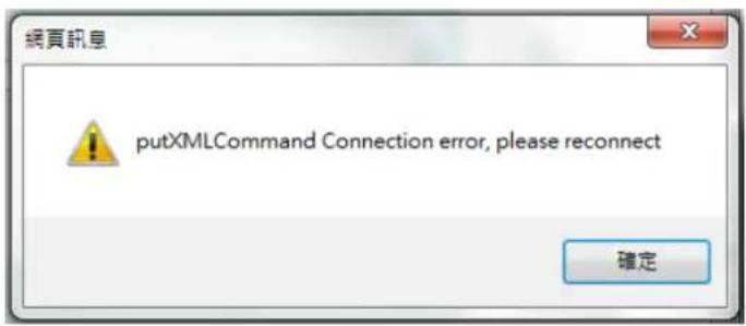
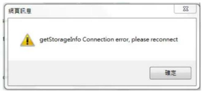
- To enter the Registry Editor of your computer: Click Start and type "regedit" in the Search Program and Files field.
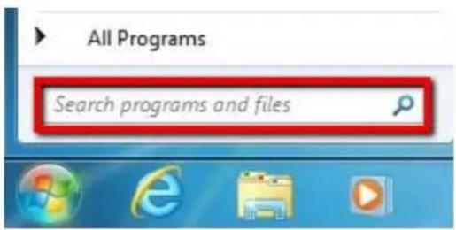
- Click the Enter button, the Registry Editor window appears.
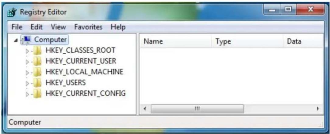
3. Find the KeepAlive Timeout Dword by following the path:
\HKEY_CURRENT_USER\Software\Microsoft\Windows\CurrentVersion\Internet Settings
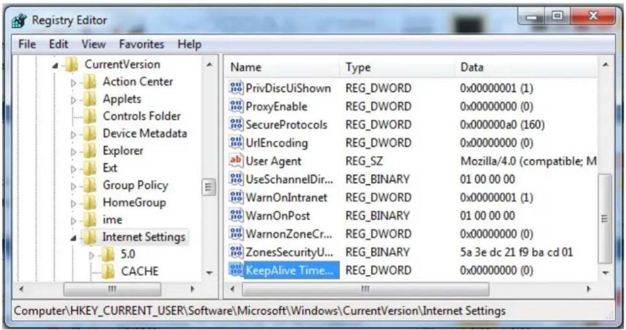
4. Double-click KeepAlive Timeout and this window appears.
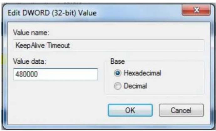
5. Change the Value data to 480000 and click OK.
B. Snapshot / Record error message.
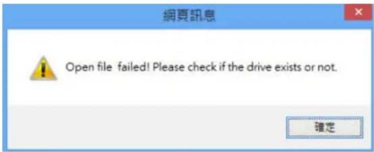
For Microsoft IE10 and above users, you may have the above error message pop up when you click the
Snapshot or Record button on the Live View window. You can simply solve this problem by setting up your Microsoft Internet Explorer to Run as administrator.
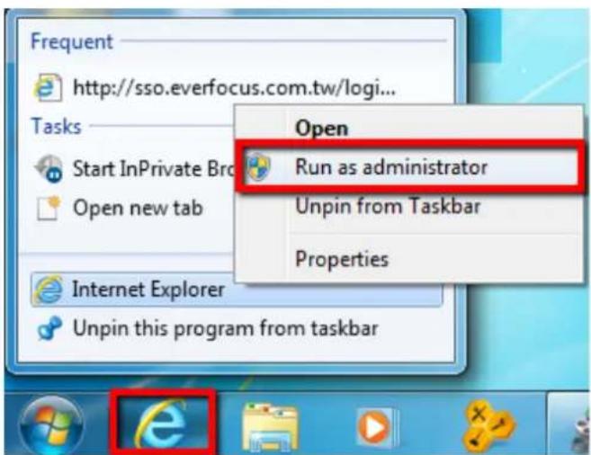
Appendix
This IP Camera supports SD / SDHC card up to 64 GB. The following brands of the SD / Micro SD cards have been tested by EverFocus and are recommended to work with EverFocus IP camera.
| Brand | ADATA | Kingston | Samsung | SanDisk | Transcend |
| Card Capacity | 64 GB | 64 GB | 64 GB | 64 GB | 64 GB |
| Card Rate Level | Class 10 | Class 10 | Class 10 | Class 10 | Class 10 |
ADATA: Premier microSDHC/SDXC UHS-I Class10
Kingston: MicroSDXC UHS-I Class10 64GB
Samsung: MicroSDXC 64GB UHS-I
SanDisk: Ultra® microSDXC™ UHS-I card
Transcend: MicroSDXC Class 10 UHS-I memory card 300x
EverFocus Electronics Corp.
EverFocus Taiwan:
12F, No.79, Sec. 1, Shin-Tai Wu Road,
Hsi-Chih, Taipei, Taiwan
TEL: +886 2 2698 2334
FAX: +886 2 2698 2380
www.everfocus.com.tw
marketing@everfocus.com.tw
EverFocus China - Beijing:
Room 609, Technology Trade Building,
Shangdi Information Industry Base,
Haidian District, Beijing 100085, China
TEL: +86 10 6297 3336\~39
FAX: +86 10 6297 1423
www.everfocus.com.cn
marketing@everfocus.com.cn
EverFocus USA - California:
1801 Highland Avenue, Unit A, Duarte, CA 91010, USA
TEL: +1 626 844 8888
FAX: +1 626 844 8838
www.everfocus.com
sales@everfocus.com
EverFocus Japan:
5F, Kinshicho City Building, 2-13-4
Koto-Bashi, Sumida-Ku, Tokyo, 130-0022, Japan
TEL: +81 3 5625 8188
FAX: +81 3 5625 8189
www.everfocus.co.jp
info@everfocus.co.jp
EverFocus India:
Suite 803, Housefin Bhavan, C-21,
Bandra Kurla Complex, Bandra (East),
Mumbai 400051, India
TEL: +91 22 6128 8700
FAX: +91 22 6128 8705
www.everfocus.in
sales@everfocus.in

Your EverFocus product is designed and manufactured with high quality materials and components which can be recycled and reused.
This symbol means that electrical and
electronic equipment, at their
end-of-life, should be disposed of
separately from your household waste.
Please, dispose of this e local community waste
fobal community waste collection/recycling centre
In the European Union there are
separate collection systems for used
electrical and electronic product.
Please, help us to conserve the
environment we live in!
4F, No. 2, D4 Building, Wan Yelong
Industrial Park, Tangtou Road, Shiyan,
Baoan, Shenzhen, Guangdong 518101, China
TEL: +86 755 2765 1313
FAX: +86 755 2765 0337
www.everfocus.com.cn
marketing@everfocus.com.cn
EverFocus USA - New York:
415 Oser Avenue, Unit S, Hauppauge, NY
11788, USA
TEL: +1 631 436 5070
FAX: +1 631 436 5027
www.everfocus.com
sales@everfocus.com
EverFocus China - Shanghai:
Room 403, Ruijin Business Center, No.96,
Zhaojiabang Road, Luwan district, Shanghai
200020, China
TEL: +86 21 6471 2229 / 6471 2291
FAX: +86 21 6471 0566
www.everfocus.com.cn
marketing@everfocus.com.cn

EverFocus®
P/N: 4605PZ3261B010A-Ver.A
- EZN Series Outdoor IR Bullet IP Camera
- About this document
- Regulatory Notices
- FCC Notice "Declaration of Conformity Information"
- Precautions
- TABLE OF CONTENTS
- Introduction
- System Requirement
- Features
- Physical Description
- Cables
- Pin Assignment for Alarm Input / Output
- 5-Axis Button
- Installation
- Packing List
- Note:
- Basic Installation
- Mounting and Wiring
- Adjust the camera angles.
- Inserting a Micro SD Card
- Accessing the User Interface
- Checking the Dynamic IP Address
- Install and then start the IPU program
- Settings for Microsoft Internet Explorer
- Connecting the Camera to the Network
- Router or LAN connection
- Direct High-Speed Connection
- One-to-One Connection (Directly from PC to IP Camera)
- Live View Window
- Live View
- Playback
- Snapshot
- Record
- Speaker / Microphone
- Setting
- Wizard
- Hallway Display (9:16): Click the Rotate button
- Video Stream
- View Size
- Language
- Digital Zoom
- One Push
- Manual Control
- Lens Control
- Status Display (info line that can be placed above video box or at bottom of page)
- Event signal icons (above video screen)
- Playback
- Remote Playback Using Playback Page
- Setting Up the Playback Function
- Inserting / Removing the Micro SD Card
- Testing the Playback Function
- Playing Back Using ARV Viewer
- Settings
- System Settings
- Network
- Protocol Settings
- IP Settings
- Port Settings
- Multicast Settings
- DDNS Settings
- HTTPS Settings
- Self-Signed Certificated
- Create Certificate Request
- Date / Time
- 【Date/Time Settings】
- Storage
- Display and Overlay
- System Maintenance
- 【Maintenance】
- System Information
- User
- Create
- Remove
- Cancel
- Black/White List
- Camera Settings
- Streaming and Audio
- Profile
- Camera
- Day/Night Settings
- Lens Settings
- Exposure Settings
- Backlight Compensation Settings
- Features
- Schedule
- Image
- 【Orientation Settings】
- Event Settings
- Event Wizard
- Event
- System Settings
- Camera Settings
- Event Settings
- Event Management
- Event Trigger Settings
- Trigger Options Settings
- Schedule Settings
- Motion Settings
- 【Trigger Options Settings】
- Notification
- Link to Smart Phone App
- MobileFocus
- for iPhone
- MobileFocusPlus
- for Android-based smart phone
- Upgrading Firmware Using IP Utility
- Troubleshooting
- Error messages pop up
- Find the KeepAlive Timeout Dword by following the path:
- Double-click KeepAlive Timeout and this window appears.
- Change the Value data to 480000 and click OK.
- Snapshot / Record error message.
- Appendix
- EverFocus Electronics Corp.
- EverFocus Taiwan:
- EverFocus China - Beijing:
- EverFocus USA - California:
- EverFocus Japan:
- EverFocus India:
- EverFocus USA - New York:
- EverFocus China - Shanghai:
Brand : EverFocus
Model : EZN3261
Category : Security Camera