MEB 102-L G - Microphone SENNHEISER - Free user manual and instructions
Find the device manual for free MEB 102-L G SENNHEISER in PDF.

User questions about MEB 102-L G SENNHEISER
0 question about this device. Answer the ones you know or ask your own.
Ask a new question about this device
Download the instructions for your Microphone in PDF format for free! Find your manual MEB 102-L G - SENNHEISER and take your electronic device back in hand. On this page are published all the documents necessary for the use of your device. MEB 102-L G by SENNHEISER.
USER MANUAL MEB 102-L G SENNHEISER
natural_image
Two identical white electronic devices with mesh surfaces, one centered on a square button (no text or symbols visible)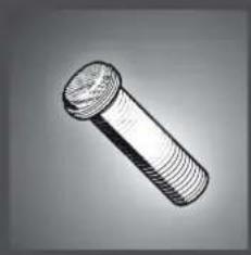
natural_image
Illustration of a threaded bolt (no text or symbols)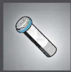
natural_image
Illustration of a threaded bolt with blue cap (no text or symbols)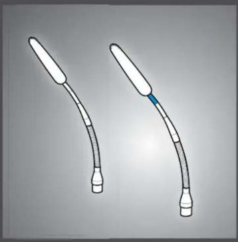
natural_image
Two medical catheters with tubes and a blue clip, shown against a plain background (no text or symbols)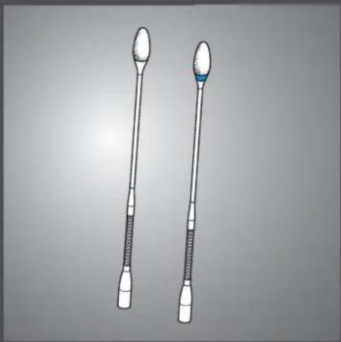
natural_image
Illustration of two types of medical or laboratory instruments with textured ends and a blue-green tip (no text or symbols)
text_image
SpeechLine IS microphone series Microphone solutions for your conference | meeting room presentation
natural_image
Two identical line drawings of a rectangular electronic device with a handle and lid, shown against a plain background (no text or symbols)
natural_image
Line drawing of a Siemens SEANHEISER industrial control unit with buttons and ports (no readable text or symbols)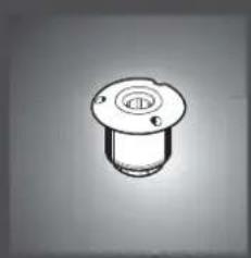
natural_image
Simple line drawing of a mechanical component with a circular top and flange (no text or symbols)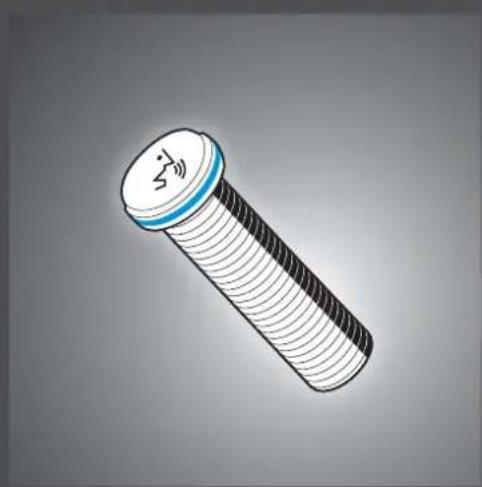
natural_image
Illustration of a bolt with a blue cap and white threaded body (no text or symbols)
natural_image
Simple line drawing of a rectangular electronic device with a handle and top panel (no text or symbols)
text_image
SpeechLine IS microphone series Microphone solutions for your conference | meeting room presentationContents
Important safety information 2
Sennheiser SpeechLine – True to the word 3
Typical applications 3
Typical ways of setting up and installing microphones 4
Pick-up patterns of the microphones 6
Positioning the microphones 6
Typical acoustic situations 8
Overview of the SpeechLine IS microphone series 9
Package contents 10
Package contents of the microphones | microphone heads 10
Package contents of the tables stands | floors stands | microphone mounts .... 11
Package contents of the inline switch box | microphone button ..... 11
Product overview 12
Overview of the MEB 114 (-S) boundary layer microphones ..... 12
Overview of the MEB 102 (-L) | MEB 104 (-L) surface-mounted boundary layer microphones .... 13
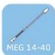
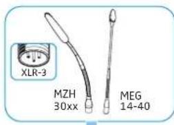
Overview of the MEG 14-40 (-L(-II)) gooseneck microphones ..... 13
Overview of the MZH 30xx (-L) goosenecks 14
Overview of the MAT 133 (-S) | MAT 153-S table stands .... 14
Overview of the MAS 133 inline switch box 15
Overview of the MAS 1 microphone button 15
Overview of the MZFS 60 | MZFS 80 microphone stands 15
Mounting and installing the products 16
Planning the position of surface-mounted products 16
Mounting surface-mounted boundary layer microphones, microphone buttons, switch boxes: table | lectern .... 18
Mounting the gooseneck microphones: table | lectern | stand ..... 20
Mounting microphones to the ceiling 22
Positioning mobile microphones 25
Connecting the products 26
Connecting the products to an audio input 26
Connecting products via the logic function 28
Adjusting and using the products 31
Adjusting the microphone sensitivity 31
Activating/deactivating the low-cut filter on the MEB 114 (-S) ..... 31
Setting the behavior of the microphone button 32
Activating/ muting microphones 33
Cleaning and maintaining the products 34
Specifications 35
Product specifications 35
Pin assignment 40
Polar diagrams 41
Frequency response curves 43
Manufacturer Declarations 45

Important safety information
▶ Please read this instruction manual carefully and completely before using the products.
▶ Always include this instruction manual when passing the products on to third parties.
▶ Do not use obviously defective products.
Preventing damage to health and accidents
▶ Position and install the products so that any risk of injury to the user is eliminated.
Keep the products, accessories and packaging parts out of reach of children and pets to prevent accidents and choking hazards.
Preventing damage to the product and malfunctions
▶ Always keep the products dry and do not expose it to extreme temperatures (hairdryer, heater, extended exposure to sunlight, etc.) to avoid corrosion or deformation.
Only clean the products with a soft, dry cloth. Solvents or cleansing agents can damage the surfaces of the products.
▶ Only use the products within the specifications indicated (see page 35).
▶ Only use attachments/ accessories/ spare parts supplied or recommended by Sennheiser.
Before operation, make sure that all I connected third party devices are in a safe operating condition and function properly.
Intended use/Liability
The products of the “IS microphone series” are designed for use in meeting rooms, conference rooms and auditoriums. Some of these products can be combined with each other.
The products can be used for commercial purposes.
It is considered improper use when the products are used for any application not named in the corresponding manuals.
Sennheiser does not accept liability for damage arising from abuse or misuse of the products and their attachments/accessories.

natural_image
Illustration of a media interview scene with three speakers on stage and audience in foreground (no text or symbols)Sennheiser SpeechLine – True to the word
The spoken word remains the most personal and powerful tool in communication. It enables us to convey and exchange messages, thoughts and opinions, as well as emotions. Therefore, when using technical devices like microphones, it is most important that no content is lost or misunderstood.
The best microphone is one you don't have to think about while speaking, because it fully captures your voice and picks up your words as precisely as you form them. Easy operation and clear speech intelligibility are perhaps most popularly embodied in the characteristically shaped Sennheiser ME 36, which can be seen on virtually every TV news program.
The qualities of these iconic microphones can also be found in all other microphones of the versatile Sennheiser SpeechLine series. These qualities are also built into any microphone of the versatile Sennheiser SpeechLine portfolio.
Wired or wireless, digital or analog, this comprehensive range of easy to integrate and unobtrusively designed microphones offer a solution for just about any situation, including yours.
In many applications, a speech microphone can help to increase the speech intelligibility or even make it possible in the first place (as in teleconferences). The following chapters describe the most common applications.
Typical applications

natural_image
Illustration of two business people seated at a round table with city skyline in background (no text or symbols)A) Conferences (voice lift)
The larger the room, the more helpful is an audio system which enhances the speech intelligibility. Especially in large conference rooms, a speaker seated at one end is difficult to understand at the other end ceiling microphones can be used to pick up what the speaker says. The audio signal can then be spread evenly around the room using wall or ceiling loudspeakers. This application is also known as “voice lift”, i.e. the speech is amplified in the room.
Table or
B) Teleconferences
If the participants of a conference are seated in different rooms, they have to be connected via telephone or remote conference circuit. As a telephone alone can only offer inadequate speech transmission for all participants in the room, table or ceiling microphones should be used in this case too. These are connected to a telephone conference unit such as the Sennheiser TeamConnect system. This processes the signals and establishes the connection to the remote participant.
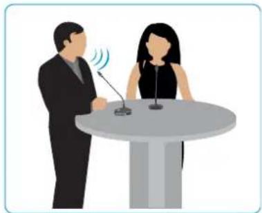
C) Presentations
Especially in a presentation, in which the focus is on the transmission of content, it is important to understand every word. Here, too, the larger the room, the more necessary it is to amplify the voice. In this case, gooseneck microphones offer the speaker orientation and enhance his presentation.

natural_image
Illustration of two people at a podium with pie charts showing percentage distribution (no text or symbols)Typical ways of setting up and installing microphones
Mobile microphones:

natural_image
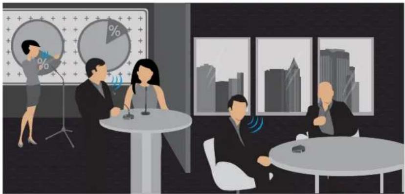
Illustration of a business meeting in an office with people seated at tables, one person presenting pie charts, and city skyline windows (no text or symbols)Permanently installed microphones:

natural_image
Illustration of a business meeting with three people at a podium, cityscape background, and pie charts showing percentage distribution (no text or symbols)A) Table
Especially in conference rooms, an obvious solution is miking up the table. Here all participants are seated around the table. Sennheiser offers mobile solutions as well as permanently installed microphones. The mobile microphones are simply placed on the table.
Mobile installation: Permanent installation:
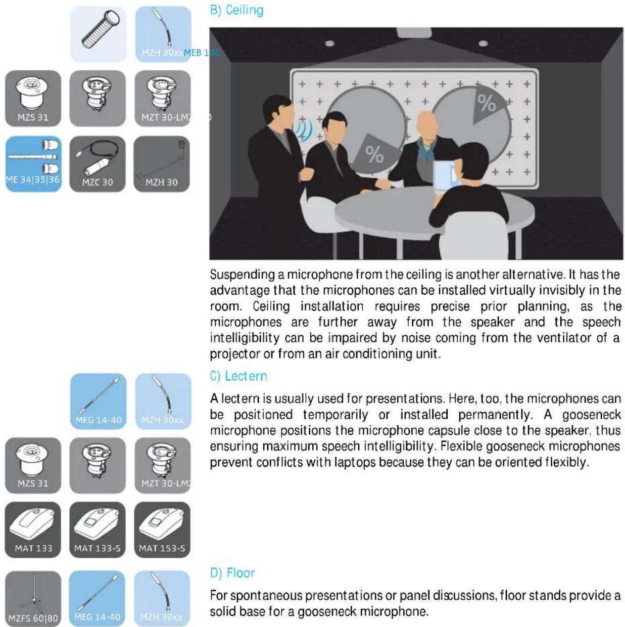
Suspending a microphone from the ceiling is another alternative. It has the advantage that the microphones can be installed virtually invisibly in the room. Ceiling installation requires precise prior planning, as the microphones are further away from the speaker and the speech intelligibility can be impaired by noise coming from the ventilator of a projector or from an air conditioning unit.
C) Lectern
A lectern is usually used for presentations. Here, too, the microphones can be positioned temporarily or installed permanently. A gooseneck microphone positions the microphone capsule close to the speaker, thus ensuring maximum speech intelligibility. Flexible gooseneck microphones prevent conflicts with laptops because they can be oriented flexibly.
D) Floor
For spontaneous presentations or panel discussions, floor stands provide a solid base for a gooseneck microphone.
Pick-up patterns of the microphones
Omni-directional pick-up pattern

An omni-directional pattern picks up the sound uniformly from all directions.


Cardioid pick-up pattern
A cardioid pattern has a wide directional characteristic, i.e. a wide opening angle. Sound hitting the rear of the microphone is attenuated very strongly.


Super-cardioid pick-up pattern
A super-cardioid pattern has a slightly stronger directional characteristic than the cardioid pattern, so it suppresses noise coming from the side even more strongly but also picks up some of the sound coming from the rear.


Super-cardioid | lobar pick-up pattern
A super-cardioid or lobar pattern has the strongest directional characteristic, i.e. it provides the maximum suppression of sound coming from the side, but it also picks up sound coming from the rear. However, the ratio is lower than it is with the super-cardioid pattern.

Positioning the microphones
A) Distance from the speaker
Basically, the nearer a speaker is to the microphone, the higher the speech intelligibility. For this reason, gooseneck microphones are optimal from an acoustic point of view. They position the microphone capsule close to the speaker while offering excellent orientation.
Boundary layer microphones do not achieve the excellent acoustic characteristics of gooseneck microphones, but they can be positioned especially unobtrusively. These microphones can be integrated into any room due to their small size and the colors they are available in. As a result of the so-called boundary layer effect, the signal picked up by the microphone capsule is amplified on a surface (for example a table or a ceiling panel). In this way, part of the distance to the speaker can be compensated for again.
B) One microphone for each speaker
In the ideal case, a dedicated microphone is used for each speaker. This allows the best possible orientation and distance to the speaker to be ensured at all times. It is also possible to choose a narrower directional characteristic. This allows noise coming from the side as well as acoustic reflections to be minimized, resulting in the highest speech intelligibility.
C) "Shared microphones" - several speakers share one microphone
One microphone per speaker is ideal, but one microphone shared by two speakers is often adequate for many applications. A microphone with a sufficiently wide opening angle should be selected here. The microphone can thus pick up both speakers if installed centrally before them.
natural_image
Illustration of two people at a podium with microphones, one speaking and the other listening (no text or symbols present)D) Typical table shapes - U-shaped, round, long, rows

natural_image
Abstract geometric pattern composed of white blocks on a dark background, no text or symbols presentDepending on the configuration of the tables in a room, different microphones can be selected. In the case of a small round table, for example, a microphone with an omni-directional pick-up pattern (shown as a blue circle) is adequate to pick up all participants uniformly. Directional microphones (shown as a semicircle) are suitable for rows of tables. These microphones minimize the sound coming from the rear and the sides. In oblong conference rooms with long tables, a combination of directional and omni-directional microphones can be a good solution.
E) Speaker is seated
For conferences in which the speakers are seated, planning is easy as the distance between the speaker and the microphone is easy to estimate or measure. Here, the microphone is simply placed on the table and oriented towards the speaker.
F) Speaker is standing
In the case of presentations held at a lectern, the speaker is usually in a standing position. Here, the distance between lectern and mouth is virtually as large as it is with a seated speaker. In courtrooms, the speakers frequently stand up although the table in front of them is often of "normal" height. In this case, long gooseneck microphones should be used ideally in order to reduce the distance between the microphone capsule and the speaker.

natural_image
Illustration of two business professionals seated at a round table with microphones (no text or symbols)
natural_image
Illustration of two people at a podium with microphones, one speaking and the other listening (no text or symbols present)Typical acoustic situations
A) Normally attenuated room
A normally attenuated room provides an average attenuation of reflections. This is contributed to by carpets, curtains or special acoustic ceilings. In the case of reduced reflections in the room, microphones pick up less noise, which results in the highest speech intelligibility.
B) Room with amplified sound
If the speech in the room is amplified by loudspeakers, this signal can enter the microphone again. This can cause echo, but in the worst case acoustic feedback can be the result. The effect can be reduced by using microphones with stronger directional characteristics.
C) Large rooms with echo – acoustically challenging rooms
The larger the room, the more probable is acoustic disturbance due to reflections or sound coming from loudspeakers. If the room also has many smooth surfaces such as glass fronts or smooth floors, the result is a scenario which is extremely unfavorable acoustically. In this case, only microphones with strong directional characteristics like the ME 36 can ensure speech intelligibility.
For assistance in selecting suitable microphones, please visit our website at www.sennheiser.com > “IS Microphone Finder” or contact your local Sennheiser partner.
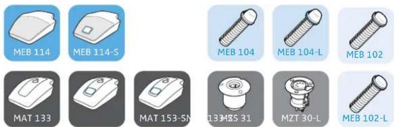
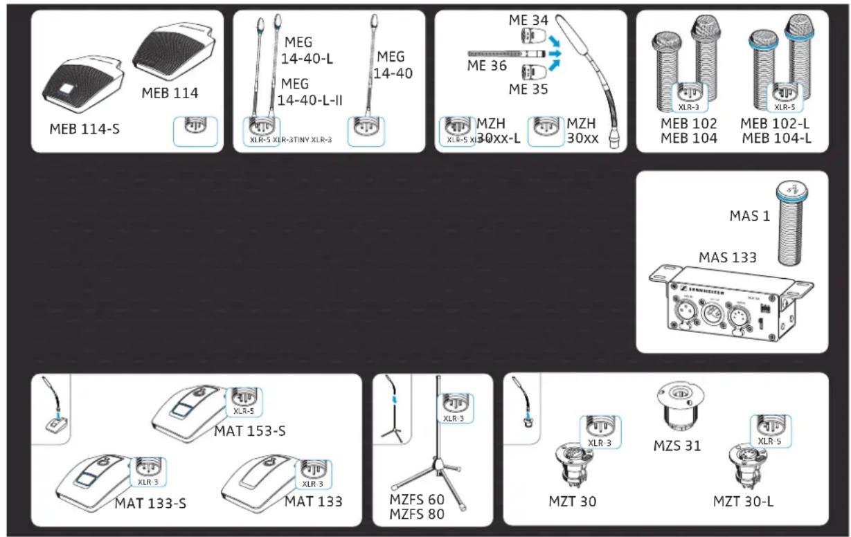
Overview of the SpeechLine IS microphone series
The SpeechLine IS microphone series offers microphones for different room and speech situations (with speakers in a standing or sitting position). Depending on the application, the microphones can be permanently mounted into tables or lecterns, mounted to the ceiling or simply set up somewhere.
text_image
MEB 114 MEG 14-40-L MEG 14-40-L-II MEG 14-40 XLR-5 XLR-3STINY XLR-3 ME 34 ME 36 ME 35 MZH 30XX-L MZH 30XX XLR-5 XLR-3 MEB 102 MEB 104 MEB 102-L MEB 104-L MAS 1 MAS 133 XLR-5 MAT 153-S XLR-3 MAT 133-S XLR-3 MZFS 60 MZFS 80 XLR-3 MZS 31 MZT 30 MZT 30-LThe series comprise the following products:
| Microphone with XLR-5 connection Microphone with XLR-3 connection | |
| Boundary layer microphones signal light ring:• MEB 102-L• MEB 104-L | Boundary layer microphones:• MEB 114 | with microphone button: MEB 114-S• MEB 102 | MEB 104 |
| Gooseneck microphones with signal light ring:• MZH 30xx-L goosenecks:MZH 3015-L, MZH 3040-L, MZH 3042-L,MZH 3062-L, MZH 3072-L with ME 34, ME 35 orME 36 microphone head• MEG 14-40-L, MEG 14-40-L-IIgooseneck microphones | Gooseneck microphones:• MZH 30xx goosenecks:MZH 3015, MZH 3040, MZH 3042, MZH 3062,MZH 3072 with ME 34, ME 35 or ME 36microphone head• MEG 14-40 gooseneck microphone |
| MAS 133 inline switch box and MAS 1 microphonebutton for controlling a microphone | |
| Table stands for gooseneck microphones:• with microphone button: MAT 153-S | Table stands for gooseneck microphones:• MAT 133 | with microphone button: MAT 133-S |
| Table mounts for gooseneck microphones:• M Z S 3 1• M Z T 3 0 - L | Table mounts for gooseneck microphones:• M Z S 3 1• M Z T 3 0 |
| Floor stands for gooseneck microphones:• MZFS 60 or MZFS 80 | |
Package contents
Depending on the product purchased, the package contents includes different components. The letters A), B) etc. stand for alternative package components.
Package contents of the microphones | microphone heads
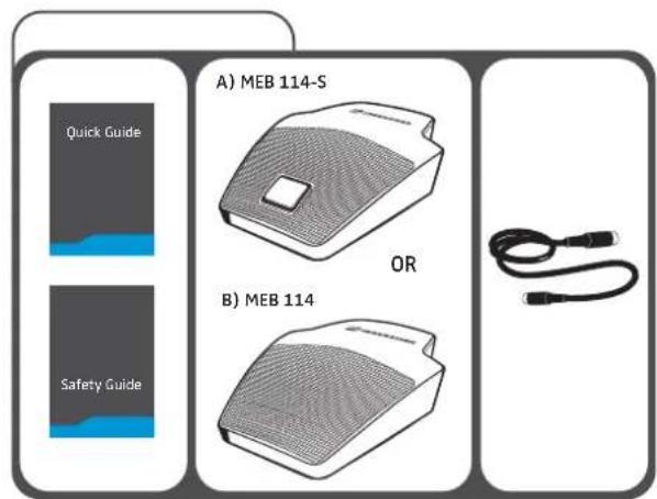
text_image
A) MEB 114-S OR B) MEB 114
text_image
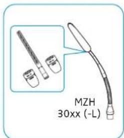
MZH 30xx(-L)MEB 114 | MEB 114-S Quick Guide Safety Guide A) MZH 30xx B) MZH 30xx (-L) OR
text_image
Quick Guide Safety Guide A) MEG 14-40 B) MEG 14-40-L C) MEG 14-40-L-II
text_image
ME 34 | ME 35 | ME 36MEG 14-40(-L(-II)) Instruction manual A) ME 34 B) ME 35 A) + B) MZW 34 OR OR C) ME 36 C) MZW 36
text_image
MEB 102 | MEB 102-L | MEB 104 | MEB 104-L Quick Guide Safety Guide A) MEB 102 B) MEB 102-L OR C) MEB 104 D) MEB 104-LPackage contents of the tables stands | floors stands | microphone mounts
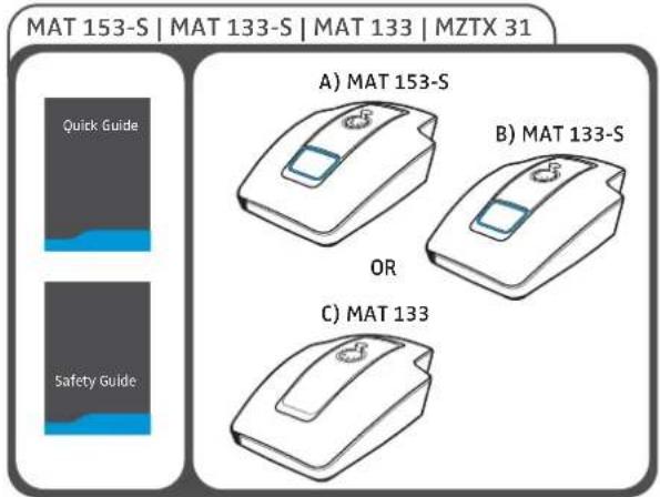
text_image
MAT 153-S | MAT 133-S | MAT 133 | MZTX 31 Quick Guide Safety Guide A) MAT 153-S B) MAT 133-S OR C) MAT 133
text_image
MZS 31 | MZT 30-L | MZT 30 Quick Guide Safety Guide A) MZS 31 B) MZT 30-L OR C) MZT 30
text_image
MZFS 60 | MZFS 80 A) MZFS 60 OR B) MZFS 80
text_image
MZC 30 | MZH 30 A) MZC 30 OR B) MZH 30 LeafletPackage contents of the inline switch box | microphone button
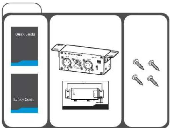
text_image
Quick Guide Safety Guide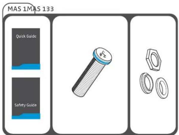
text_image
MAS 1MAS 133 Quick Guide Safety Guide
For more information on the complete SpeechLine IS microphone series and for the data sheets of the individual components, please visit our website at www.sennheiser.com.
For information on suppliers, contact your local Sennheiser partner:
www.sennheiser.com > "Service & Support"
Product overview
The pin assignment of the products can be found on page 40.
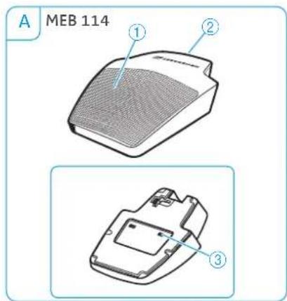
Overview of the MEB 114 (-S) boundary layer microphones
text_image
A MEB 114 ① ② ③1 Microphone
2 TINY-XLR-3 socket
3 Low cut filter

text_image
B MEB 114-S ① ② ⑥ ⑤ ④ ③4 Slide switch for setting the behavior of the microphone button
5 Logic port
6 Microphone button with signal light ring (red/green)
Overview of the MEB 102 (-L) | MEB 104 (-L) surface-mounted boundary layer microphones

text_image
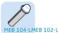
A MEB 102 ① ② ③ C MEB 104 MEB 104-L1 Microphone head
2 Threaded bolt

text_image
B MEB 102-L ① ④ ② ③ D XLR-5XLR-3 ① ④ ② ③3 Connection socket, XLR
4 Signal light ring (red/green)
| Variants Features | ||
| A MEB 102 omni-directional | ||
| B MEB 102-L omni-directional, with signal light ring | ||
| C MEB 104 cardioid, acoustically directional | ||
| D MEB 104-L cardioid, acoustically directional,with signal light ring | ||
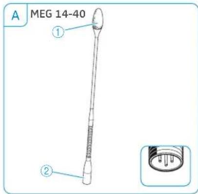
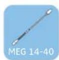
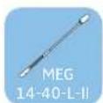
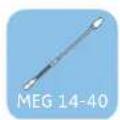
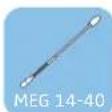
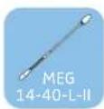
Overview of the MEG 14-40 (-L(-II)) gooseneck microphones
text_image
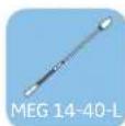
A MEG 14-40 ① ②1 Microphone head
2 Connection socket, XLR

text_image
B MEG 14-40-L MEG 14-40-L II ① ③ ② XLR-5XLR-33 Signal light ring
-red:MEG 14-40-L
-green: MEG 14-40-L II
| Variant Features | ||
| A | MEG 14-40 cardioid, acoustically directional | |
| B | MEG 14-40-L (-II) cardioid, acoustically directional, with signal light ring | |
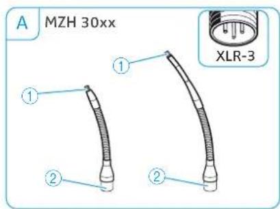
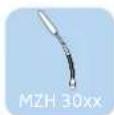
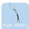
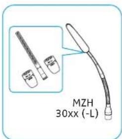
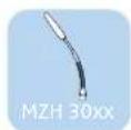
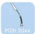
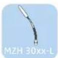
Overview of the MZH 30xx (-L) goosenecks
text_image
A MZH 30xx ① ② ① ② XLR-31 Thread for ME 34/35/36 microphone heads
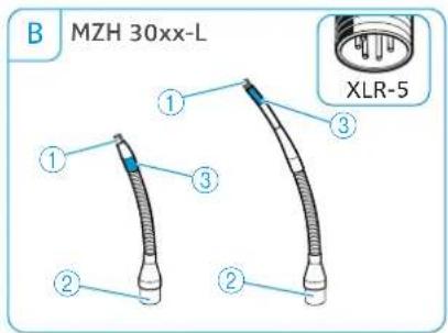
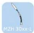
text_image
B MZH 30xx-L ① ③ ② ② XLR-52 Connection socket, XLR
3 Signal light ring (red/green)
| Microphone head Features | |
| ME 34 cardioid, acoustically directional | |
| ME 35 super-cardioid, acoustically directional | |
| ME 36 super-cardioid/ lobar, acoustically directional | |
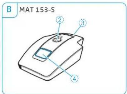
Overview of the MAT 133 (-S) | MAT 153-S table stands

text_image
A MAT 133 ① ③
text_image
C MAT 133-S ① ③ ④1 Socket for gooseneck microphone, XLR-3
2 Socket for gooseneck microphone, XLR-5
3 Connection socket, XLR-3
text_image
B MAT 153-S ② ③ ④
text_image
MAT 133-S MAT 153-S4 Microphone button with signal light ring (red/green)
5 Logic port
6 Slide switch for setting the behavior of the microphone button
Overview of the MAS 133 inline switch box

text_image
SENNHEISER MAS 133 mic in mic out switch ON ON PTM FTT ON ① ② ③ ④ ⑤ ⑥1 Mounting brackets
2 mi c in microphone input.
XLR-3F
3 mi c out microphone output, XLR-3M
4 switch socket for MAS 1 microphone button, XLR-5F
5 Slide switch for setting the behavior of the microphone button
6 logi c out output
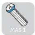
Overview of the MAS 1 microphone button

text_image
Technical diagram of a mechanical component with numbered parts and an inset view showing internal structure.1 Microphone button
2 Signal light ring (red/green)
3 Socket for inline switch box, XLR-5M
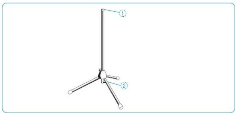
Overview of the MZFS 60 | MZFS 80 microphone stands
text_image
Technical diagram of a tripod-mounted device with labeled parts ① and ②1 Microphone connection, XLR-3F 2 Connection socket, XLR-3M
Mounting and installing the products
Planning the position of surface-mounted products
Planning the position of surface-mounted microphones | microphone buttons | inline switch boxes on tables and lecterns

natural_image
Illustration of a business meeting with three people, a speaker at a podium, and pie charts in the background (no text or symbols)


Choose the positions of surface-mo united microphones, microphone buttons, table mounts, shock mounts and inline switch boxes on e.g. lecterns or conference tables so that
– the speakers don't hit their knees when sitting down,
- the distance between speaker and microphone is between 30 cm to 80 cm (best possible speech quality),
– the microphone buttons are easy to reach for the speakers and
- no disruptive objects, sources of disturbance (e.g. telephones or PC fans) or movable parts are in close proximity to the microphones.

text_image
min. 30 cm max. 80 cm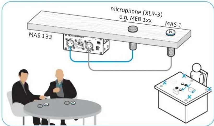
text_image
microphone (XLR-3) e.g. MEB 1xx MAS 1 MAS 133 MAS 1Planning the position of microphones | microphones accessories on a ceiling

natural_image
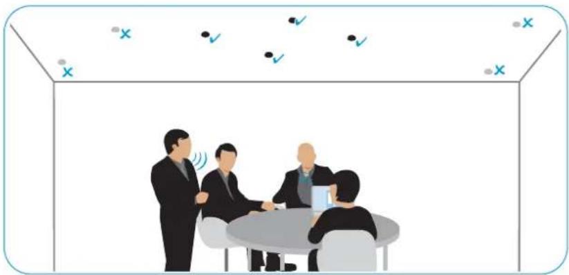
Illustration of four business people in a meeting with pie charts on the wall (no text or symbols)To mount the product to a ceiling panel or wooden board:

text_image
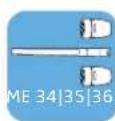
MEB 102 MZH 30xx-L MZS 31 MZT 30 ME 34|35|36 MZH 30 MZC 30Choose the positions of the microphones or flush mounts on the ceiling so that
– they are located directly above or in close proximity to the speaker, – neither the speaker nor other persons can hit their heads on the microphones or can get caught in hanging cables.
When ceiling mounting, observe the applicable fire protection requirements for the building.
natural_image
Illustration of four business people in a meeting room with checkmarks and X symbols above (no text or labels)Mounting surface-mounted boundary layer microphones, microphone buttons, switch boxes: table | lectern
Drilling a hole through the surface of the table or lectern
Once you have chosen a position for the product (see page 16):
Drill a hole with a diameter of 2.5 mm through the mounting surface (plate thickness: 10 mm - 65 mm).

text_image
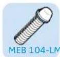
MEB 102 MEB 102-L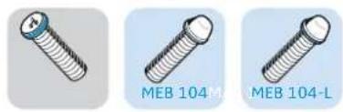
natural_image
Three different types of screws labeled MEB 104M, MEB 104-L, and an unlabeled one (no text or symbols on the screws themselves)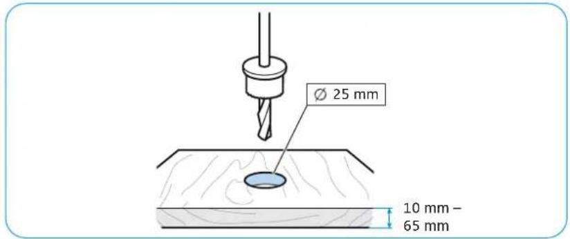
text_image
Ø 25 mm 10 mm - 65 mmMounting the MEB 102 (-L) | MEB 104 (-L) boundary layer microphones


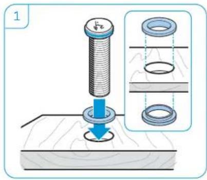
1 Slide the first rubber ring over the threaded bolt of the microphone and then insert the microphone into the drilled hole.
2 Orient the MEB 104 and MEB 104-L microphones towards the speaker. Slide the second rubber ring over the threaded bolt and tighten the hex nut.

text_image
1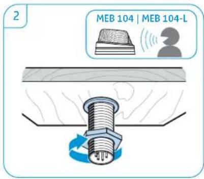
text_image
2 MEB 104 | MEB 104-LMounting the MAS 1 microphone button
1 Slide the first rubber ring over the threaded bolt of the microphone button and then insert the microphone into the drilled hole.
2 Slide the second rubber ring over the threaded bolt and tighten the hex nut.
text_image
1
natural_image
Illustration of a bolt and nut assembly with a rotating screw (no text or symbols)
Mounting the MAS 133 inline switch box
If necessary, change the position of the mounting brackets by loosening the screws and removing the covers from the drilled holes. Attach the mounting brackets to the desired position and replace the covers.
▶ Use the drilling template (see supplement) to mark the position of the screws.
Attach the inline switch box using the supplied recessed head screws.

text_image
MU-T18 MU-T18 MU-T18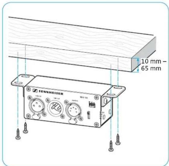
text_image
10 mm - 65 mm SENNHEISER MA3 124Mounting the gooseneck microphones: table | lectern | stand
You can mount the gooseneck microphones:
A) to mobile table stands,
B) to floor stands and
C) to surface-mounted table mounts or shock mounts.
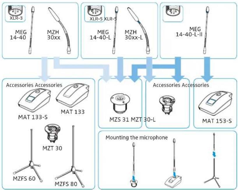
flowchart
graph TD
    A["Accessories Accessories"] --> B["Mounting the microphone"]
    A --> C["MZS 31 MZT 30-L"]
    A --> D["MAT 153-S"]
    A --> E["MZFS 60"]
    A --> F["MZFS 80"]
    A --> G["MZT 30"]
    A --> H["MAT 133"]
    A --> I["MAT 133-S"]
    A --> J["MZH 30xx"]
    A --> K["XLR-3"]
    A --> L["XLR-5 XLR-5"]
    A --> M["XLR-40-L"]
    A --> N["XLR-40-L-II"]
Mounting the ME 3x microphone head onto the MZH gooseneck
Tightly screw one of the microphone heads onto the gooseneck in order to ensure a reliable ground connection.
text_image
MZH 30xx (-L)
text_image
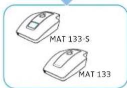
ME 34 ME 36 ME 35 MZH 30xxA) Mounting the MEG/MZH gooseneck microphone onto the MAT table stand
Connect the XLR connector of the gooseneck microphone to the corresponding socket of the table stand.
▶ Orient the microphone towards the speaker.

text_image
XLR-3 MZH 30xx MEG 14-40
text_image
XLR-S MEG 14-40-L-II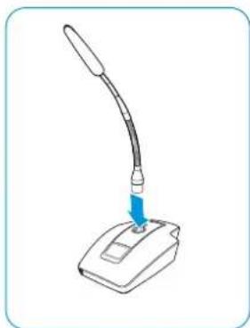
natural_image
Illustration of a desktop computer with a curved arm and a blue arrow pointing to the screen (no text or symbols)


text_image
MAT 133-S MAT 133
text_image
MAT 153-S
B) Mounting the MEG/MZH gooseneck microphone to the MZFS floor stand
Connect the XLR connector of the gooseneck microphone to the corresponding socket of the floor stand.

text_image
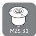
XLR 3 MEG 14-40 MZH 30xx MZFS 60 MZFS 80C) Mounting the MEG/MZH gooseneck microphone to the MZT table mount/MZS shock mount
Once you have chosen a position for the product (see page 16):


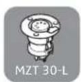
1 Drill a hole with the following diameter through the mounting surface (plate thickness 10 mm - 65 mm):
- 24 mm for the MZT 30 (-L) table mount
- 51 mm for the MZS 31 shock mount
text_image
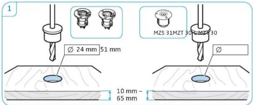
1 Ø 24 mm 51 mm MZS 31MZT 30 L MZT 30 10 mm - 65 mm2 Insert the table mount or the shock mount into the drilled hole.
3 Connect the XLR connector of the gooseneck microphone to the corresponding socket of the MZT 30 (-L) table mount/MZS 31 shock mount.

text_image
2 MZT 30 MZS 31 MZT 30-L
natural_image
Illustration of a medical procedure showing a needle inserted into a circular component on a surface (no text or symbols)Mounting microphones to the ceiling
Some microphones of the IS series can also be mounted to a ceiling panel or wooden board of a suspended ceiling.


text_image
A MEB 102 XLR-3 B MZH 3015w + MZT 30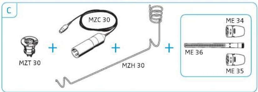
text_image
C MZT 30 + MZC 30 + MZH 30 + ME 34 ME 36 ME 35A) Mounting the MEB 102 boundary layer to the ceiling
Once you have chosen a position for the product (see page 16):
Drill a hole with a diameter of 25 mm through the ceiling panel or wooden board (plate thickness 10 mm - 65 mm).

text_image
10 mm - 65 mm Ø 25 mm▶ Slide the first rubber ring over the threaded bolt of the microphone button and then insert the microphone into the drilled hole.
▶ Slide the second rubber ring over the threaded bolt and tighten the hex nut.

text_image
Diagram illustrating a mechanical assembly with a bolt, ring, and washer, showing structural change and assembly details.
natural_image
Illustration of a bolt being inserted into a wooden surface, showing mechanical fastening (no text or symbols)Connect a suitable cable (see page 26) and lay the cable.


B) Mounting the MZH 3015 w gooseneck microphone to the ceiling
Tightly screw one of the microphone heads o n to the gooseneck in order to ensure a reliable ground connection.
text_image
MZH 30xx (-L)
text_image
ME 34 ME 36 ME 35 MZH 30xxOnce you have chosen a position for the product (see page 16):
Drill a hole with the following diameter through the mounting surface (plate thickness 10 mm - 65 mm):
- 24 mm for the MZT 30 table mount
- 51 mm for the MZS 31 shock mount

text_image
10 mm - 65 mm Ø 51 mm 24 mm MZT 30 M2Insert the table mount or the shock mount into the drilled hole.
Connect the XLR connector of the gooseneck microphone to the corresponding socket of the MZT 30 table mount/MZS 31 shock mount.
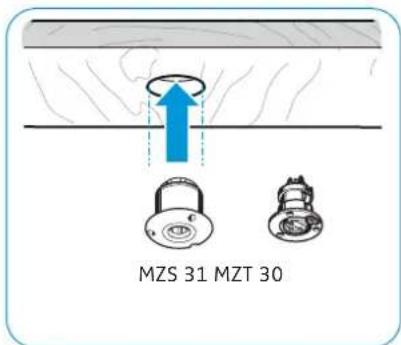
text_image
MZS 31 MZT 30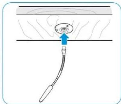
natural_image
Diagram of a medical or surgical procedure showing a tool inserted into a circular component with an arrow indicating direction (no text or symbols present)Connect a suitable cable (see page 26) and lay the cable.


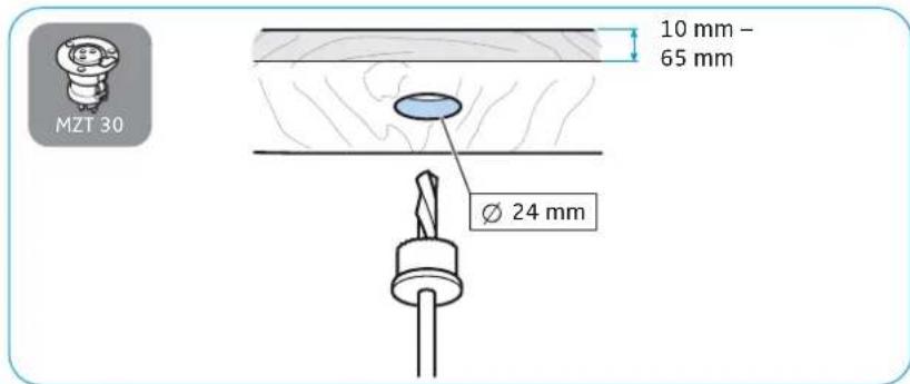
C) Ceiling-mounting a ME 3x microphone
Once you have chosen a position for the product (see page 16):
Drill a hole with a diameter of 2.4 mm through the mounting surface (plate thickness 10 mm - 65 mm).
text_image
MZT 30 10 mm - 65 mm Ø 24 mmInsert the table mount into the drilled hole.
Connect the XLR connector of the MZC 30 cable to the corresponding socket of the MZT 30 table mount.

text_image
MZT 30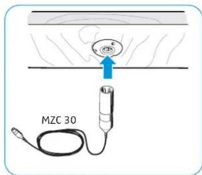
text_image
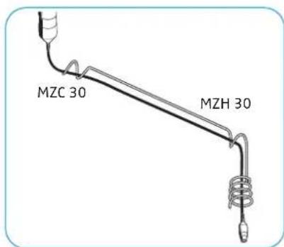
MZC 30▶ Guide the cable through the MZH 3 0 metal ceiling hanger.
Tightly screw one of the microphone heads onto the special coax socket of the cable in order to ensure a reliable ground connection.
text_image
MZC 30 MZH 30
text_image
ME 34 ME 36 ME 35 MZC 30Connect a suitable cable (see page 26) and lay the cable.
Positioning mobile microphones
natural_image
Illustration of a business meeting in an office with people, a pie chart, and cityscape background (no text or symbols)Positioning tabletop boundary layer microphones/gooseneck microphones attached to a table stand
Choose the positions of the microphone so that
- the distance between speaker and microphone is between 30 cm to 80 cm (best possible speech quality) and - no disruptive objects, sources of disturbance (e.g. PC fans) or movable parts are in close proximity to the microphones.
Orient the gooseneck microphones towards the speaker.
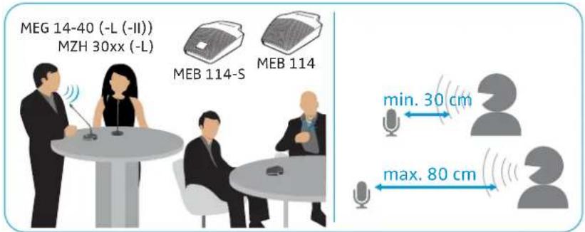
text_image
MEG 14-40 (-L (-II)) MZH 30xx (-L) MEB 114-S MEB 114 min. 30 cm max. 80 cmPositioning gooseneck microphones attached to a stand
▶ Position the stand with the microphone so that the distance between speaker and microphone is between 30 cm to 80 cm (best possible speech quality).
▶ Orient the gooseneck microphones towards the speaker.
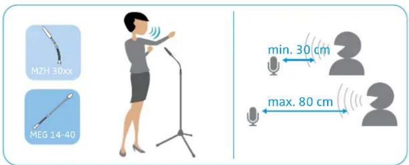
text_image
MZH 30xx MEG 14-40 min. 30 cm max. 80 cm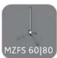
Connecting the products
Connecting the products to an audio input


There are two ways to connect the products of the SpeechLine IS microphone series to a suitable audio input:
A) Connection to a mixing console, an auto mixer or a digital signal processor (DSP) using shielded cables
B) Connection to a mixing console via the MAS 133 inline switch box and the MAS 1 microphone button using shielded XLR cables
A) Connecting a microphone to a mixing console | an auto mixer | a digital signal processor (DSP)
Use a suitable shielded cable (e.g. XLR-XLR, XLR-terminal) to connect the microphone to the mixing console, the auto mixer or the DSP. For more information on the connections, refer to the instruction manual of your DSP.
Lay all cables in such a way that other persons cannot trip over them and injure themselves.

text_image
MEB 114 MEB 114-S TINY XLR-3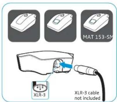
text_image
MAT 153-SM XLR-3 XLR-3 cable not included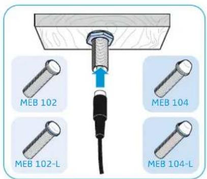
text_image
MEB 102 MEB 104 MEB 102-L MEB 104-L
text_image
MZH MZH 30xx MEG 14-40 MZH 30xx-L MEG 14-40L


B) Connecting a microphone | the MAS 133 inline switch box | the MAS 1 microphone button to a mixing console
▶ Use a shielded XLR-3 cable to connect the MAS 1 microphone button to the MAS 133 inline switch box (switch socket).
Use a shielded XLR-3 cable each to connect the MAS 133 inline switch box to:
- the microphone (MAS 133: mic in socket) and
- the mixing console (MAS 133: mic out socket).

text_image
microphone (XLR-3) e.g. MEB 1xx MAS 1 MAS 133 MAS 1


Connecting products via the logic function
Once you have established the audio connection (see previous chapter), you can connect the products of the IS microphone series featuring a logic port (shown on the left) to the DSP.
The logic port passes on status information on the microphone button (microphone button pressed/ not pressed) to the DSP. Via the logic output of the DSP, you can additionally control the status of the signal light ring of the microphone button.
The logic output also allows you to integrate and control several MAS 133 inline switch boxes in a system.
The following chapters provide
A) information on how to connect the MAS 133 inline switch box to a DSP
B) information on how to connect microphones
C) an example installation for the Se nnheiser TeamConnect system
A) Connecting the MAS 133 inline switch box to the DSP via the logic function
The way you connect the MAS 133 inline switch box determines which information is passed on to the DSP.
Logic port Function

Passes on status information on the microphone button – button pressed/ not pressed– to the DSP.

Passes on microphone status information – microphone activated/muted – to the DSP.
Use a 2-wire cable ( 0.14–0.5 mm ^2 ) to connect the inline switch box to a GPIO port or logic port of the DSP.
Lay all cables in such a way that other persons cannot trip over them and injure themselves.
▶ Observe the connection instructions in the instruction manual of your DSP.
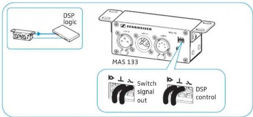
text_image
DSP logic MENHEISER MAS 133 Switch signal out DSP controlB) Connecting microphones to a DSP with logic function
To establish a logic connection in addition to the audio connection:
Use a 3-wire cable ( 0.14–0.5 mm ^2 ) to connect the microphone or the table stand to a GPIO port or logic port of the DSP.
Lay all cables in such a way that other persons cannot trip over them and injure themselves.
Observe the connection instructions in the instruction manual of your DSP.
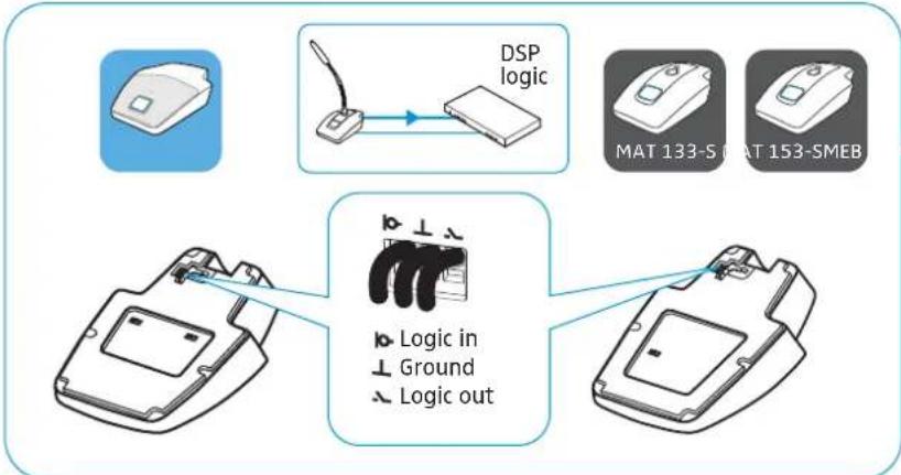
flowchart
graph TD
    A["Device with DSP Logic"] --> B["DSP logic"]
    B --> C["Device with MAT 133-S and MAT 153-SMEB"]
    C --> D["Device with Logic in Ground Logic out"]
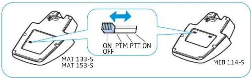
▶ Set the slide switch for setting the behavior of the microphone button to ON in order to activate the "DSP remote mode". In "DSP remote mode", the microphone is permanently on and is muted or activated via the DSP. The microphone thus permanently provides a reference signal for AEC algorithms in the DSP.
text_image
MAT 133-S MAT 153-S ON PTM PTT ON OFF MEB 114-SC) Example installation for the Sennheiser TeamConnect system
Example installation with an XLR-3 microphone

text_image
Audio Logic
flowchart
graph TD
    A["Audio"] --> B["MEB 114-S"]
    B --> C["Logic"]
    C --> D["CONTROL / STATU"]
    D --> E["Sennheiser SL TeamConnect CB1"]
    E --> F["Sennheiser SL TeamConnect CU1"]
    F --> G["Power Supply"]
    style A fill:#f9f,stroke:#333
    style B fill:#ccf,stroke:#333
    style C fill:#cfc,stroke:#333
    style D fill:#fcc,stroke:#333
    style E fill:#cff,stroke:#333
    style F fill:#ffc,stroke:#333
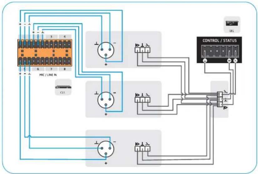
text_image
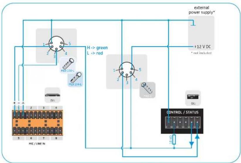
MIC / LINE IN CONTROL / STATUSExample installation with an XLR-5 microphone and signal light rings
flowchart
graph TD
    A["Microcontroller 5"] -->|1| B["Indicator Light 1"]
    A -->|2| C["Indicator Light 2"]
    A -->|3| D["Indicator Light 3"]
    A -->|4| E["Indicator Light 4"]
    F["External Power Supply*"] --> G["+12 V DC * not included"]
    H["Control / STATUS"] --> I["External Power Supply*"]
    J["CU3"] --> K["MC / LINE IN"]
    L["H→ green L→ red"] --> M["MC 102-"]
    N["MCS 104-L"] --> O["MC 102-"]
    P["DB1"] --> Q["DB1"]
Adjusting and using the products
Adjusting the microphone sensitivity
Use the mixing console, the auto mixer or the DSP to adjust the microphone sensitivity so that over- or under-modulation is avoided. For more information on the audio settings, refer to the instruction manual of the corresponding device.
If interference occurs at high field strengths, remove the source of interference from the microphone.
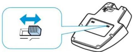
Activating/deactivating the low-cut filter on the MEB 114 (-S)


A table or lectern transfers the sound produced when a speaker accidentally stumbles against it. The low-cut filter reduces low-frequency noise by filtering out frequencies below 120 Hz.
▶ Set the slide switch to the desired position:

Low-cut filter is deactivated
Low-cut filter is activated
natural_image
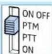
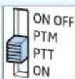
Diagram showing a device with bidirectional arrow and internal components, no text or symbols presentSetting the behavior of the microphone button


The products shown on the left feature a slide switch that allows you to directly set the behavior of the microphone button.
▶ Set the slide switch to the desired position.
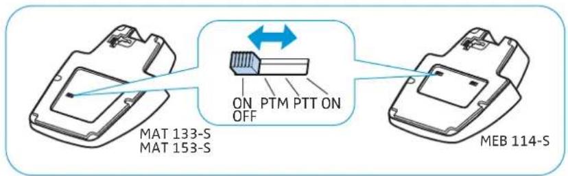
text_image
MAT 133-S MAT 153-S ON PTM PTT ON OFF MEB 114-S
text_image
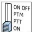
SENNHEISER MAS 133 ON OFF PTM PTT ON MAS 133Position Function

ON/OFF:
When you press the microphone button, the microphone is:
- activated (lights up green) or
- muted (lights up red).
PTM – Push To Mute:
The microphone is activated, the microphone button lights up green. The microphone button will light up red and the microphone will be muted for as long as you keep the microphone button pressed.
PTT – Push To Talk:
The microphone is muted, the microphone button lights up red. The microphone button will light up green and the microphone will be activated for as long as you keep the microphone button pressed.

ON:
- Protection against accidental operation: The microphone is permanently activated. This setting prevents interruptions due to accidental operation of the microphone button.
- DSP remote mode: The microphone is connected to a DSP via a logic port. In this case, the functions ON, OFF, PTT and PTM can be performed by the DSP.

Activating/muting microphones
The products shown on the left have LEDs that indicate whether the microphone is muted or activated. The LEDs light up as so products are powered via the mixing console, the auto mixer or the DSP.
Whether a microphone is permanently activated or muted or whether it can be activated or muted by pressing the microphone button depends on the setting of the slide switch that sets the behavior of the microphone button (see page 32). When the slide switch is set to ON, the microphone is permanently activated and the microphone button is deactivated.
▶ Press the microphone button, the LED lights up:
... green Microphone is active
... red* Microphone is muted

text_image
MEB 114-S MAT 133-S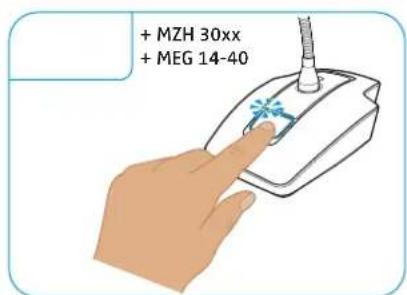
text_image
+ MZH 30xx + MEG 14-40
text_image
MAS 1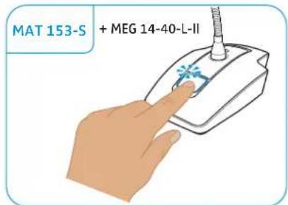
text_image
MAT 153-S + MEG 14-40-L-II* This function is not supported by all mixing consoles, auto mixers and DSPs.
The signal light rings of the microphones light up synchronously with the signal light rings of the microphone buttons.
Cleaning and maintaining the products
CAUTION
Liquids can damage the electronics of the products!
Liquids entering the housing of the product can short-circuit the electronics.
▶ Keep all liquids far away from the product.
Do not use any solvents or cleansing agents.
▶ Clean the products with a soft, dry cloth.
Specifications
Product specifications

Boundary layer microphones MEB 114 MEB 114-S
| Pick-up pattern cardioid | ||
| Frequency response 40 – 20,000 Hz | ||
| Acoustic principle boundary layer microphone | ||
| Switch for behavior of the microphone button | -ON | PTM | PTT | ON/OFF | |
| Cut-off frequency 120 Hz | ||
| Output impedance at 1kHz 200 Ω | ||
| Sensitivity 10 mV/ Pa | ||
| Max. sound pressure level 140 dB at 1 kHz | ||
| Equivalent noise level A-weighted as per DIN IEC 61672 | 29 dB(A) | |
| Power supply 24 – 48 V phantom power (P 24 – P 48) | ||
| Current consumption 1,5 mA 5.3 mA | (microphone/signal light ring: 2.65 mA each) | |
| Logic input – high level input voltage > 2.0 V | low level input voltage < 0.8 V | |
| Logic output | - | high level output voltage > 2.4 V low level output voltage < 0.4 V |
| Connector | tiny XLR-3M | tiny XLR-3M | 3 x terminal |
| Weight | approx. 286 g | |
| Dimensions (W x H x D) | 85 mm x 25 mm x 100 mm | |
| Temperature | operation: -10 °C (14 °F) to +50 °C (122°F) storage: -25 °C (-13°F) to +70 °C (158°F) | |
 |  |  |  | |
| Surface-mounted boundary layer microphones | MEB 102 MEB 102-L MEB 104 MEB 104-L | |||
| Pick-up pattern omni-directional cardioid | ||||
| Frequency response 40 – 20,000 Hz | ||||
| Acoustic principle boundary layer microphone | ||||
| Output impedance at 1kHz 200 Ω | ||||
| Sensitivity 16 mV/Pa 14 mV/Pa | ||||
| Max. sound pressure level 125 dB at 1 kHz < 3% | ||||
| Equivalent noise level A-weighted as per DIN IEC 61672 | 21 dB (A) 28 dB (A) | |||
| Power supply 24 – 48 V phantom power (P 24 – P 48) | ||||
| Current consumption 3 mA 6 mA | (microphone/ signal light ring: 3 mA each) | 3 mA | 6 mA (microphone/ signal light ring: 3 mA each) | |
| Connector | XLR-3M | XLR-5M | XLR-3M | XLR-5M |
| Weight Dimensions | approx. 59 g | approx. 60 g | ||
| installation height: approx. 12 mm | installation height: approx. 19 mm | |||
| total height: approx. 83 mm | total height: approx. 90 mm | |||
| ∅ microphone head: approx. 29 mm | ||||
| ∅ threaded bolt: approx. 20 mm | ||||
| thread size: M20 x 1.5 | ||||
| ∅ rubber rings: approx. 23 mm | ||||
| Temperature | operation: -10 °C (14 °F) to +50 °C (122°F) storage: -25 °C (-13°F) to +70 °C (158°F) | |||
| Gooseneck microphones | MZH 30xx | MZH 30xx-L | ||
| Pick-up pattern | depending on ME 3x mic head | |||
| Acoustic principle | gooseneck microphone (condenser) | |||
| Power supply | 12 V – 48 V phantom power (P 12 – P 48) | |||
| Current consumption | 3 mA | 18 mA (microphone/ signal light ring: 9 mA each) | ||
| Connector | XLR-3M | XLR-5M | ||
| Temperature | operation: 0 °C (32 °F) to +40 °C (104 °F) storage: -25 °C (-13°F) to +70 °C (158°F) | |||


Gooseneck microphones MEG 14-40 MEG 14-40-L MEG 14-40-L-II
Pick-up pattern cardioid
Frequency response 50 – 20,000 Hz
Acoustic principle gooseneck microphone (condenser)
Output impedance at 1kHz < 100 Ω
Sensitivity 15 mV/Pa
Max. sound pressure level 130 dB at 1 kHz < 3%
Equivalent noise level 37 dB (CCIR)
26 dB (A)
Power supply 12 V - 48 V
phantom power (P 12 - P 48)
Current consumption 3 mA
Power supply signal light ring - 9 - 30 V DC
approx. 18 mA red
12 – 30 V DC 1 – 18 mA green
Connector
XLR-3M
XLR-5M
Temperature
operation: 0 °C (32 °F) to +40 °C (104 °F) storage: -25 °C (-13°F) to +70 °C (158°F)


ME 34 ME 35 ME 36
Pick-up pattern
Frequency response
Acoustic principle
cardioid
super-cardioid
hyper-cardioid/lobar
40 - 20.000 Hz
50 - 20.000 Hz
40 - 20.000 Hz
pressure gradient transducer
pressure gradient transducer
pressure gradient transducer/ interference tube transducer
10 mV/Pa
18 mV/Pa
Sensitivity
Electrical impedance
Min. terminating impedance
Equivalent noise level
50 Ω
1 Ω
37 dB (CCIR) 26 dB (A)
34 dB (CCIR) 23 dB (A)
12 V - 48 V phantom power (P 12 - P 48)
Power supply via MZH 30xx
Current consumption microphone
Dimensions (W x H x D)
Weight without MZH 30xx
Connector
Temperature
250 μA
∅ 12 x L18
∅ 8.2 x L96
9.5 g
17 g
special coax connector
operation: -10^ (14°F) to +50^ (122°F)
storage: -25^ (-13^) to +70^ (158°F)
MAS 133 inline switch box
Power supply 48 V phantom power (P48) via MIC IN
Slide switch for setting the ON | PTM | PTT | ON/OFF
behavior of the microphone button
Logic output high level output voltage > 2.4 V | low level output voltage < 0.4 V
Connections MIC IN: XLR-3F | MIC OUT: XLR-3M | SWITCH: XLR-5F | 3x terminal
Weight approx. 212 g
Dimensions (W x H x D) approx. 150 x 44 x 44 mm
Temperature operation: -10^(14^) to +50^(122^)
storage: -25^ ( -13^ ) to +70^ ( 158^ )
MAS 1 microphone button

Power supply 12 V (max. 1.5 mA)
Current consumption signal light ring: 3 mA
Connection XLR-5M
Weight approx. 59 g
Dimensions total height: approx. 81 mm
installation height: approx. 8 mm
∅-head of microphone button: approx. 29 mm
∅-threaded bolt: approx. 20 mm
∅-rubber rings: approx. 23 mm
thread size: M20 x 1.5
Temperature operation: -10^(14^) to +50^(122^)
storage: -25^ ( -13^ ) to +70^ ( 158^ )


| Table stands MAT 133 MAT 133-S MAT 153-S | |||
| Current consumption 1.9 mA 3.7 mA | |||
| Slide switch for setting the behavior of the microphone button | -ON | PTM | PTT | ON/OFF | ||
| Logic input - high level input voltage >2.0 V | low level input voltage >0.8 V | ||
| Logic output - high level output voltage >2.4 V | low level output voltage >0.4 V | ||
| Connector MIC IN: XLR-3F | MIC OUT: XLR-3M | MIC IN: XLR-3F | MIC IN: XLR-5F |
| MIC OUT: XLR-3M | MIC OUT: XLR-3M | ||
| 3 x terminal | 3 x terminal | ||
| Power supply | 48 V phantom power (P 48) | ||
| Weight approx. 1200 g approx. 1206 g | |||
| Dimensions (W x H x D) 120 mm x 43 mm x 170 mm | |||
| Temperature | operation: -10 °C (14 °F) to +50 °C (122°F) storage: -25 °C (-13°F) to +70 °C (158°F) | ||
| MZS 31 | MZT 30 | MZT 30-L | |
| Shock mount/table mounts | MZS 31 | MZT 30 | MZT 30-L |
| Connector | - | XLR-3F | XLR-5F |
| Power supply | 48 V phantom power (P 48) | ||
| Weight approx. 1200 g approx. 1206 g | |||
| Dimensions (W x H x D) 120 mm x 43 mm x 170 mm | |||
| Temperature | operation: -10 °C (14 °F) to +50 °C (122°F) storage: -25 °C (-13°F) to +7O °C (158°F) | ||
MZC 30 connection cable for ceiling mounting
| Connections | XLR-3M | special coax socket for ME 3x |
| Power supply | 12 – 48 V phantom power (P 12 – P 48) |
| Length | 9 m |
| Diameter | 1.1 mm |
In compliance with
Europe
CE
EMC:
• EN 55103-1
EN 55103-2

In case of interference from extraneous devices, the specifications may differ from those listed above.
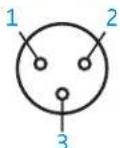
Pin assignment
MEB 102 | MEB 104: XLR-3
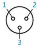


1 Ground
2 Microphone +
3 Microphone –
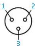
MEG 14-40 | MZH 30xx: XLR-3

1 Ground
2 Microphone +
3 Microphone -
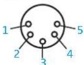
MEG 14-40-L-II: XLR 5
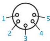
1 Microphone Ground
2 Microphone +
3 Microphone -
4 LED Ground
5 LED: 12 - 30 V
MAS 133: XLR 3 mic in

1 Ground
2 Microphone +
3 Microphone -
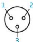
MEB 114: XLR 3
1 Ground
2 Microphone +
3 Microphone –
MAS 133: XLR 3 mic out
1 Microphone –
2 Microphone +
3 Ground
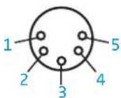
MEB 102-L | MEB 104-L: XLR-5
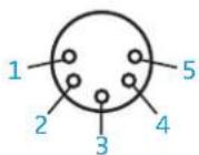

1 Ground
2 Microphone +
3 Microphone –
4 LED (H -> green, L -> red)
5 LED (H -> red)
MEG 14-40-L | MZH 30xx-L: XLR-5

1 Ground
2 Microphone +
3 Microphone -
4 LED: 9 - 30 V DC any polarity
5 LED: 9 - 30 V DC any polarity
MAS 1: XLR 3 mic in


1 Switch
2 Switch
3 red
4 green
5 LEDs +12 V
MAS 133: XLR 5 switch
1 Ground
2 Switch
3 LED red -
4 LED green -
5 LEDs +12 V
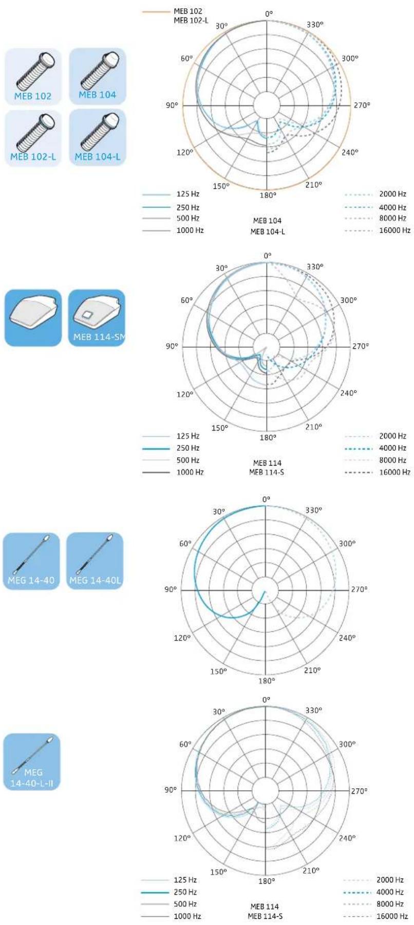
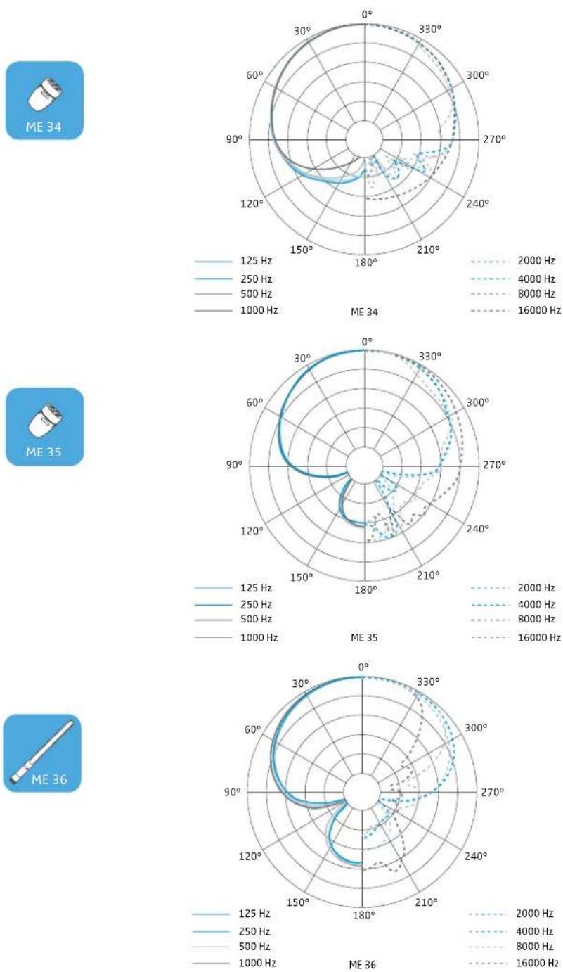
Polar diagrams
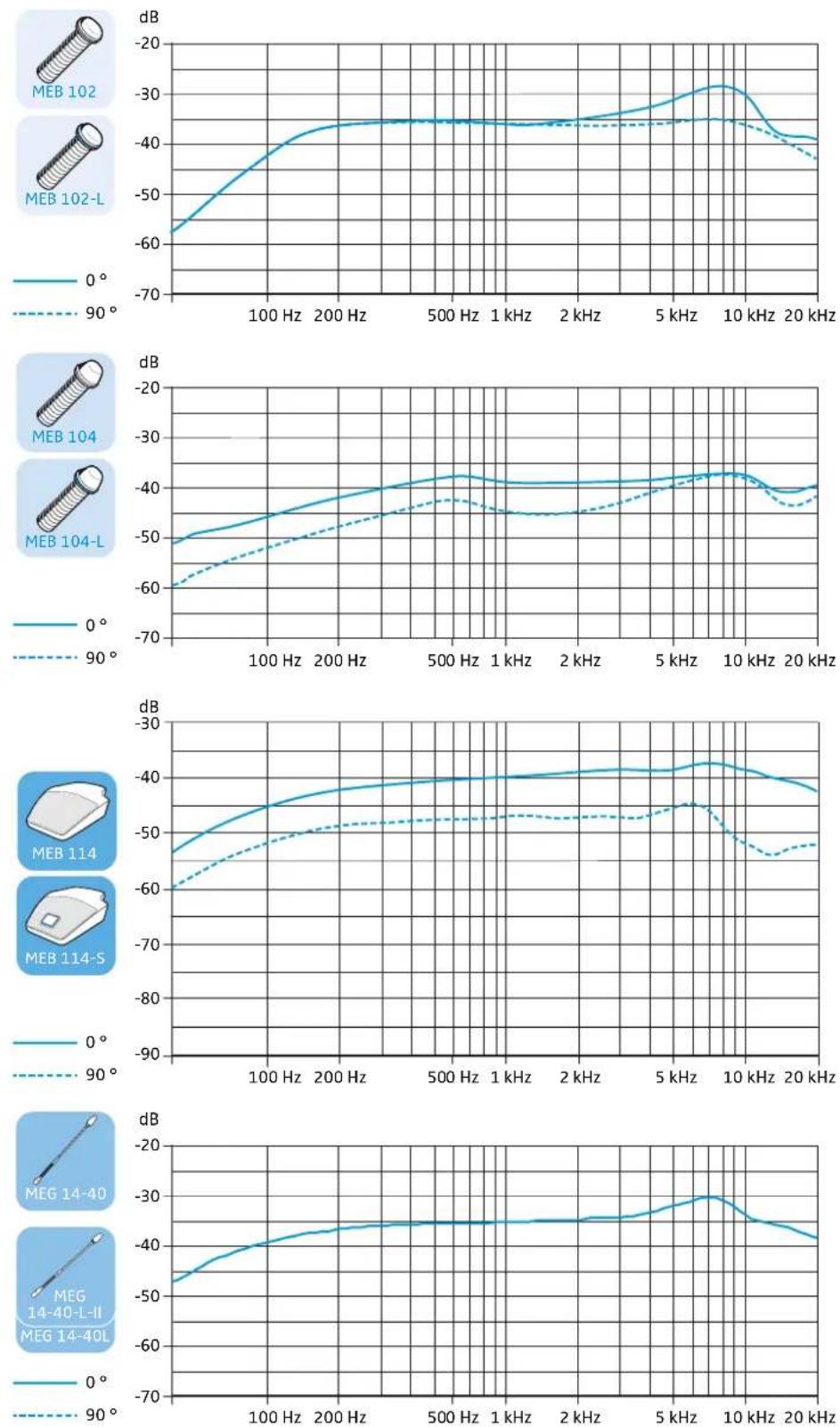
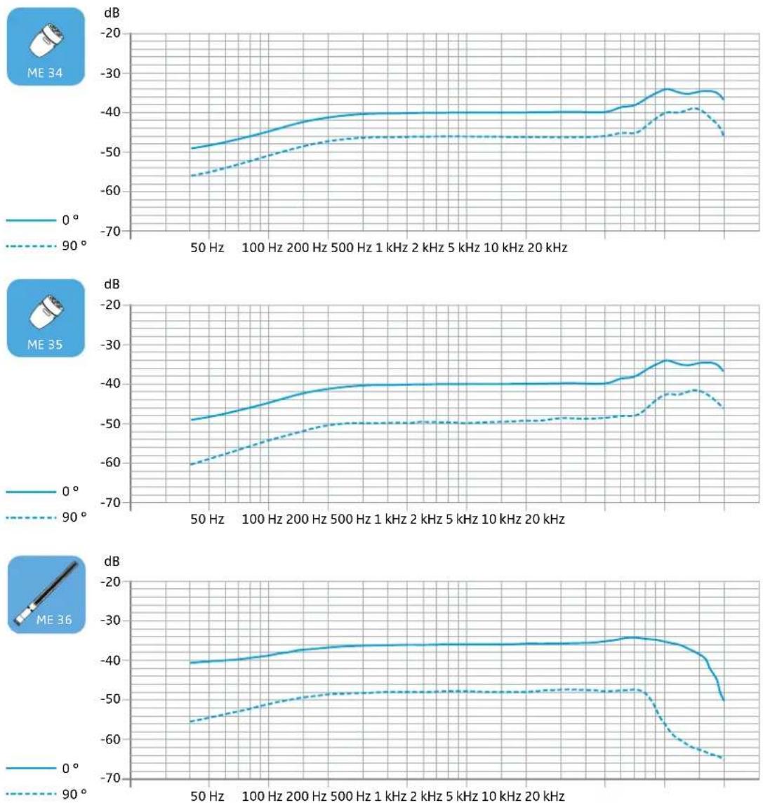
Frequency response curves
Manufacturer Declarations
Warranty
Sennheiser electronic GmbH & Co. KG gives a warranty of 24 months on this product.
For the current warranty conditions, please visit our website at www.sennheiser.com or contact your Sennheiser partner.
In compliance with the following requirements

- WEEE Directive (2012/19/EU) Please dispose of the products at the end of their operational lifetime by taking them to your local collection point or recycling center for such equipment.
• Australia/New Zealand

CE Conformity
• RoHS Directive (2011/65/EU)
• EMC Directive (2014/30/EU)
The declaration is available at www.senncom.com. Before putting the products into operation, please observe the respective country-specific regulations!

SENNHEISER
Sennheiser electronic GmbH & Co. KG
Am Labor 1, 30900 Wedemark, Germany
www.sennheiser.com
Publ. 02/15, 554665, A04