Rocsecure NE52 - NAS Rocstor - Free user manual and instructions
Find the device manual for free Rocsecure NE52 Rocstor in PDF.


| Product Type | NAS (Network Attached Storage) |
| Model | Rocsecure NE52 |
| Brand | Rocstor |
| CPU | Intel Celeron Quad Core 2.0 GHz |
| Memory | 8 GB DDR3 SDRAM |
| Drive Bays | 5 x 2.5" or 3.5" hot-swappable SATA 6 Gb/s |
| RAID Levels | 0, 1, 5, 6, 10, Linear (JBOD) |
| Network Interfaces | 2 x Gigabit Ethernet (RJ-45) |
| USB Ports | 1 x USB 3.0, 2 x USB 2.0 |
| eSATA Port | 1 x eSATA 6 Gb/s |
| Video Output | HDMI x 2, DVI-I (via adapter) |
| Serial Port | 1 x RS-232 |
| LCD Panel | Yes, smart-functional with menu navigation |
| Power Supply | 300 W with PFC (80 plus), AC 100-240 V, 6.3 A, 50-60 Hz |
| Dimensions (H x W x D) | 261 x 180 x 390 mm |
| Operating Temperature | 10°C to 40°C (50°F to 104°F) |
| Humidity | 10% to 85% non-condensing |
| Hot Swap & Auto Rebuild | Supported |
| Event Notification | Audible alarm, LED indicators |
Frequently Asked Questions - Rocsecure NE52 Rocstor
User questions about Rocsecure NE52 Rocstor
0 question about this device. Answer the ones you know or ask your own.
Ask a new question about this device
Download the instructions for your NAS in PDF format for free! Find your manual Rocsecure NE52 - Rocstor and take your electronic device back in hand. On this page are published all the documents necessary for the use of your device. Rocsecure NE52 by Rocstor.
USER MANUAL Rocsecure NE52 Rocstor
Packaging, Shipment and Delivery....4
Chapter 1 Introduction....5
1.1 Key Features....5
1.2 Technical Specifications....6
Chapter 2 Installation....7
2.1 Packaging, Shipment and Delivery....7
2.2 Unpacking the NAS System....7
2.3 Identifying Parts of the NAS System 8
2.3.1 Front View 8
2.3.2 HDD Status LEDs....9
2.3.3 Fan Fail LED....9
2.3.4 Lock Indicator....9
2.3.5 Front Panel....10
2.3.6 Rear View....11
2.3.7 LCD Menu Diagram....12
2.4 Getting Started with the NAS System....13
2.4.1 NAS Hardware Setup....13
2.4.2 Installing Hard Drives 13
2.4.2.1 Installing 3.5" Disk in a Disk Tray....13
2.4.2.2 Installing 2.5" Disk in a Disk Tray....15
Preface
About this manual
This manual provides information regarding the quick installation and hardware features of the NAS system. Information contained in the manual has been reviewed for accuracy, but not for product warranty because of the various environment/OS/settings. Information and specifications will be changed without further notice.
This manual uses section numbering for every topics being discussed for easy and convenient way of finding information in accordance with the user's needs. The following icons are being used for some details and information to be considered in going through with this manual:

NOTES:
These are notes that contain useful information and tips that the user must give attention to in going through with the subsystem operation.

IMPORTANT!
These are the important information that the user must remember.

WARNING!
These are the warnings that the user must follow to avoid unnecessary errors and bodily injury during hardware and software operation of the subsystem.

CAUTION:
These are the cautions that user must be aware to prevent damage to the equipment and its components.
Copyright
2016 Rocstor. No part of this publication may be reproduced, stored in a retrieval system, or transmitted in any form or by any means, electronic, mechanical, photocopying, recording or otherwise, without the prior written consent.
Trademarks
All products and trade names used in this document are trademarks of Rocstor or registered trademarks of their respective owners.
Changes
The material in this document is for information only and is subject to change without notice.
Before You Begin
Before going through with this manual, you should read and focus to the following safety guidelines. Notes about the subsystem product packaging and delivery are also included.
Safety Guidelines
To provide reasonable protection against any harm on the part of the user and to obtain maximum performance, user is advised to be aware of the following safety guidelines particularly in handling hardware components:
Upon receiving of the product:
Place the product in its proper location.
To avoid unnecessary dropping out, make sure that somebody is around for immediate assistance.
It should be handled with care to avoid dropping that may cause damage to the product. Always use the correct lifting procedures.
Upon installing of the product:
- Ambient temperature is very important for the installation site. It must not exceed 30°C. Due to seasonal climate changes; regulate the installation site temperature making it not to exceed the allowed ambient temperature.
Before plugging-in any power cords, cables and connectors, make sure that the power switches are turned off. Disconnect first any power connection if the power supply module is being removed from the enclosure. - Outlets must be accessible to the equipment.
All external connections should be made using shielded cables and as much as possible should not be performed by bare hand. Using anti-static hand gloves is recommended.
In installing components, secure all the mounting screws and locks. Make sure that all screws are fully tightened. Follow correctly all the listed procedures in this manual for reliable performance.
Packaging, Shipment and Delivery
Before removing the subsystem from the shipping carton, you should visually inspect the physical condition of the shipping carton.
✿ Unpack the subsystem and verify that the contents of the shipping carton are all there and in good condition.
- Exterior damage to the shipping carton may indicate that the contents of the carton are damaged.
If any damage is found, do not remove the components; contact the dealer where you purchased the subsystem for further instructions.
Chapter 1 Introduction
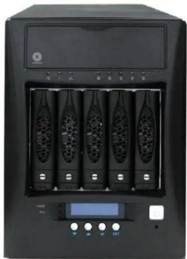
natural_image
Front view of a black server rack with five vertical channels and a digital display (no visible text or labels)The NAS System
1.1 Key Features
- Supports up to five (5) hot-swappable 6Gb/s SATA hard drives
- Supports RAID levels 0, 1, 5, 6, 10 and Linear(JBOD)
- Support Smart-functional LCD panel
- Support drive hot spare and automatic hot rebuild
- Centralization of Data and Storage Management
- Real-time drive activity and status indicators
- Environmental monitoring unit
- Locally audible event notification alarm
1.2 Technical Specifications
| Hardware Platform |
| Intel Celeron Quad Core 2.0GHz CPU |
| Cache memory : 8GB DDR3 SDRAM |
| One USB3.0, one eSATA and two USB2.0 ports |
| Two Gigabit Ethernet ports |
| Up to Five(5) 2.5"/3.5" hot-swappable 6Gb/s SATA hard drives |
| Real-time drive activity and status indicators |
| Environmental monitoring unit |
| 300W power supply with PFC (80 plus) |
| Support drive hot spare and automatic hot rebuild |
| Locally audible event notification alarm |
| Power requirements |
| AC 100V ~ 240V Full range |
| 6.3A, 50~60Hz |
| Environmental |
| Relative humidity : 10%~85% Non-condensing |
| Operating temp : 10°C~40°C(50°F~104°F) |
| Physical Dimension |
| 261(H) x 180(W) x 390(D)mm |
Specifications are subject to change without notice.
Chapter 2 Installation
2.1 Packaging, Shipment and Delivery
Before removing the system from the shipping carton, you should visually inspect the physical condition of the shipping carton.
✿ Unpack the system and verify that the contents of the shipping carton are all there and in good condition.
- Exterior damage to the shipping carton may indicate that the contents of the carton are damaged.
If any damage is found, do not remove the components; contact the dealer where you purchased the system for further instructions.
2.2 Unpacking the NAS System
The package contains the following items:
 | NAS System Unit |
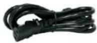 | One (1) power cord |
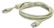 | Two (2) Ethernet LAN cables |
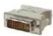 | One (1) DVI-I to VGA Adaptor |
 | User Manual |
If any of these items are missing or damaged, please contact your dealer or sales representative for assistance.
2.3 Identifying Parts of the NAS System
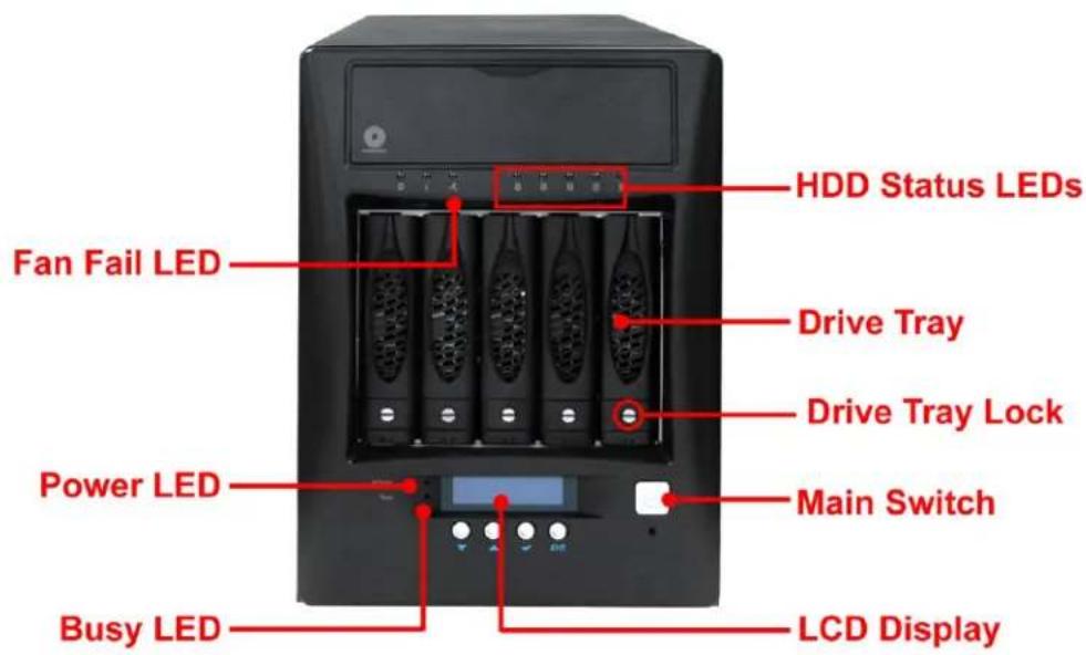
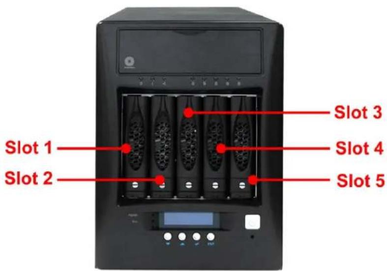
The illustrations below identify the various parts of the NAS system.
2.3.1 Front View
2.3.2 HDD Status LEDs
natural_image
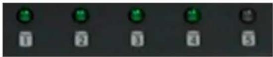
Pure electrical control buttons without any text or symbolsGreen LED indicates power is on and the hard disk drive status is good for this slot. Blinking Orange and Green LED indicates the hard disk drive is in rebuilding state.
2.3.3 Fan Fail LED

| Parts | Function |
| Fan Fail LED | When fan fails, this LED will turn red and an alarm will sound. |
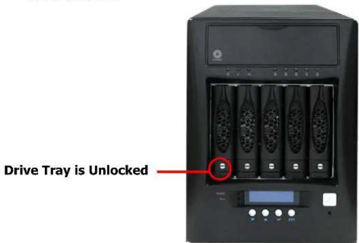
2.3.4 Lock Indicator
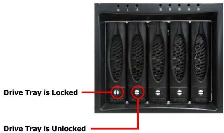
Every Drive Carrier is lockable and is fitted with a lock indicator to indicate whether or not the carrier is locked into the chassis. Each carrier is also fitted with an ergonomic handle for easy carrier removal.
2.3.5 Front Panel
| PARTS | FUNCTION |
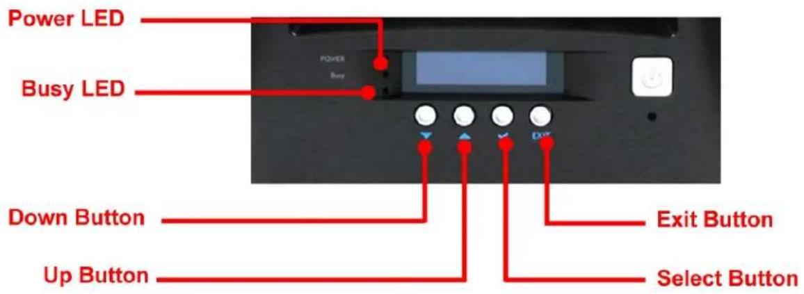
| Power LED | Green LED indicates power is on. |
| Busy LED | Orange blinking indicates system is busy or data is being accessed. |
Up and Down Arrow buttons  | Use the Up or Down arrow keys to go through the information on the LCD screen. This is also used to move between each menu when you configure the subsystem. |
Select button  | This is used to enter the option you have selected. |
| Exit button EXIT | Press this button to return to the previous menu. |
2.3.6 Rear View
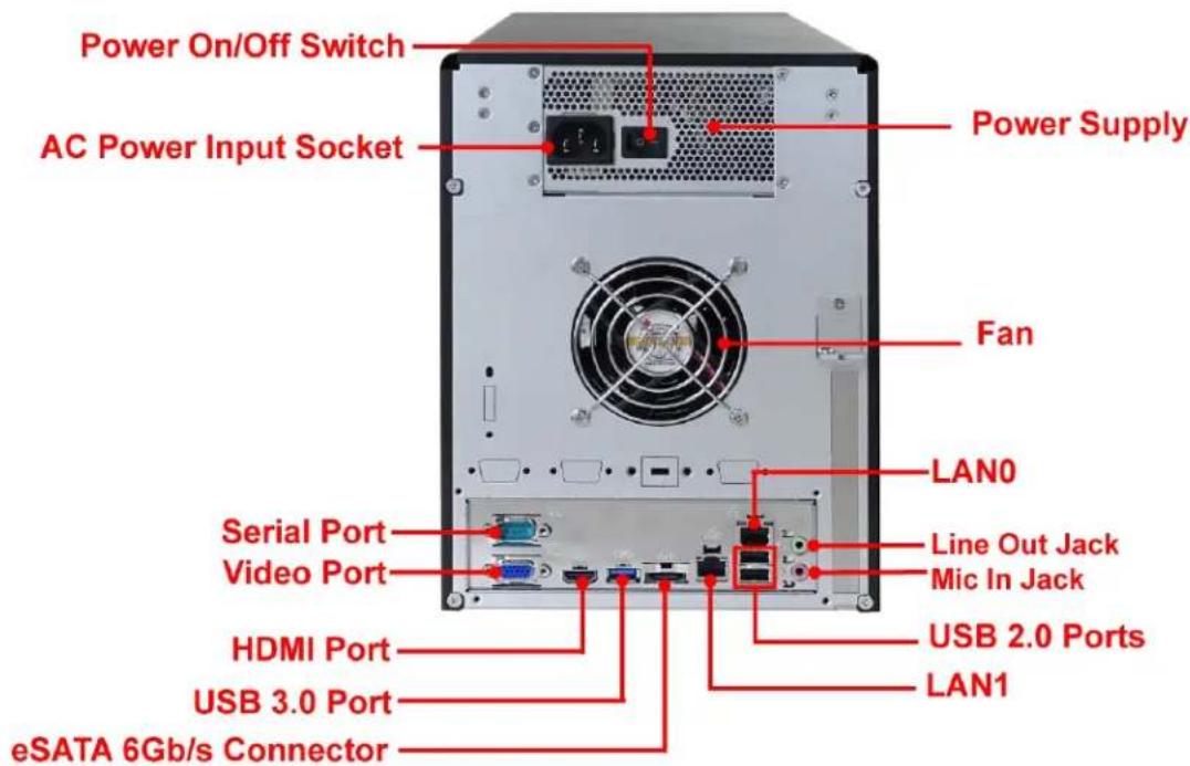
- Power On/Off Switch - Use this switch to power on the NAS System.
- AC Power Input Socket - Use this to connect the power cords connected from power source.
- Serial Port - Connects to serial-based mouse or data processing devices.
- Video Port - The video in port allows connect to video in, which can also apply to video loop thru function.
- HDMI Port - Two HDMI port is located at the rear of the system. HDMI (High-Definition Multimedia Interface) is an all-digital audio/video interface capable of transmitting uncompressed audio/video signals.
- USB 3.0 Port - The USB 3.0 port supports the USB 3.0 specification and is compatible to the USB 2.0/1.1 specification.
- eSATA 6Gb/s Connector - The subsystem has one external eSATA port for connecting to other eSATA device.
- Power Supply - The NAS System has one power supply.
- LAN0 and LAN1 Gigabit ports – The NAS System has two Gigabit data ports.
- USB 2.0 ports - Two USB 2.0 ports are located at the rear of the system.
2.3.7 LCD Menu Diagram
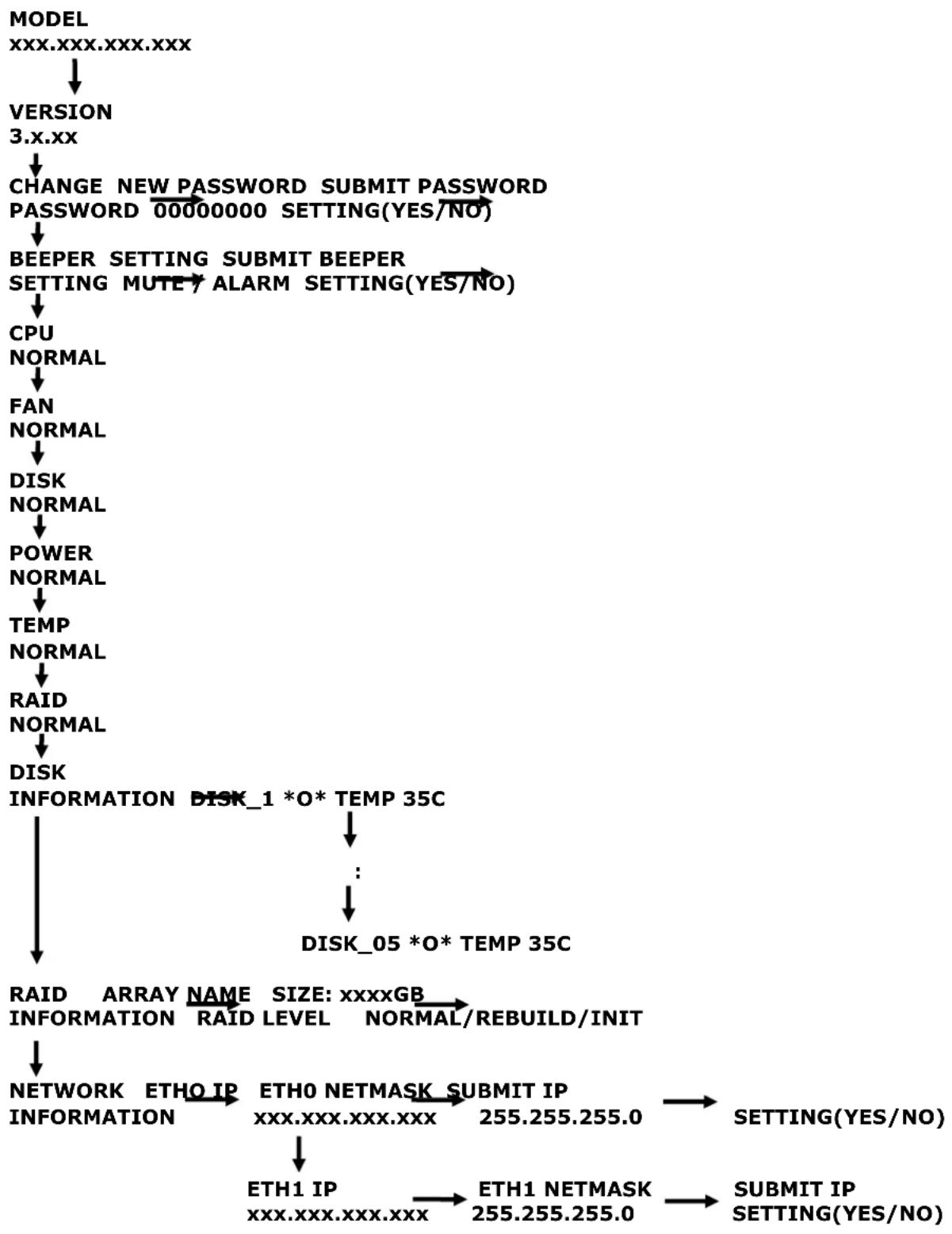
flowchart
graph TD
    A["MODEL<br>XXX.XXX.XXX.XXX"] --> B["VERSION<br>3.x.xx"]
    B --> C["CHANGE NEW PASSWORD<br>PASSWORD 00000000 SETTING(YES/NO)"]
    C --> D["BEEPER SETTING<br>SETTING MUTY ALARM SETTING(YES/NO)"]
    D --> E["CPU<br>NORMAL"]
    E --> F["FAN<br>NORMAL"]
    F --> G["DISK<br>NORMAL"]
    G --> H["POWER<br>NORMAL"]
    H --> I["TEMP<br>NORMAL"]
    I --> J["RAID<br>NORMAL"]
    J --> K["DISK<br>INFORMATION DISK_1 *O* TEMP 35C"]
    K --> L["..."]
    L --> M["DISK_05 *O* TEMP 35C"]
    M --> N["RAID ARRAY NAME SIZE: xxxxGB<br>INFORMATION RAID LEVEL NORMAL/REBUILD/INIT"]
    N --> O["NETWORK ETHO IP<br>INFORMATION"]
    O --> P["ETHO NETMASK SUBMIT IP<br>xxx.XXX.XXX.XXX"]
    P --> Q["ETH1 IP<br>xxx.XXX.XXX.XXX"]
    Q --> R["ETH1 NETMASK<br>255.255.255.0"]
    R --> S["SETTING(YES/NO)"]
    S --> T["SUBMIT IP<br>SETTING(YES/NO)"]
2.4 Getting Started with the NAS System
2.4.1 NAS Hardware Setup
- Attach network cable to LAN0 Ethernet port. Connect the other end of network cable to your network hub or switch. You may also connect the other Ethernet ports if needed.
- Plug in the power cord into the AC Power Input Socket located at the rear of the subsystem.
- To turn on the NAS, press the Power On/Off Switch of power supply at the rear. Then turn on the main switch button in the front panel.
- The Power LED on the front panel will turn green.
2.4.2 Installing Hard Drives
2.4.2.1 Installing 3.5" Disk in a Disk Tray
This section describes the location of the hard drives in the NAS system and gives instructions on installing a hard drive. The system supports hot-swapping allowing you to install or replace a hard drive while the system is running.
a. Make sure the lock indicator is in unlocked position. To pull out a disk tray, press the Lock Indicator Button. Pull the handle outwards to remove the disk tray from the enclosure.
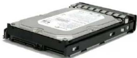
b. Place the hard drive in the disk tray.
natural_image
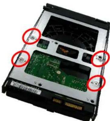
Exterior view of a black hard drive chassis (no visible text or labels)c. Make sure the holes of the disk tray align with the holes of the hard drive. Install the mounting screws on the bottom part to secure the drive in the disk tray.
natural_image
Close-up of a computer hard drive chassis showing internal circuit board and memory components (no text or symbols visible)Tray Hole A
d. Slide the tray into a slot and push the Lock Indicator Button.
e. Press the handle until you hear the latch click into place. The HDD status LED will turn green if subsystem is on.
2.4.2.2 Installing 2.5" Disk in a Disk Tray
a. Make sure the lock indicator is in unlocked position. To pull out a disk tray, press the carrier open button.
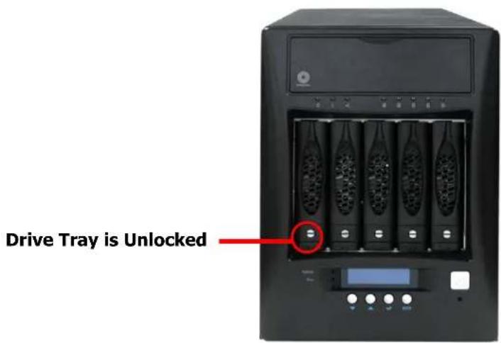
b. Pull out an empty disk tray. Pull the lever handle outwards to remove the carrier from the enclosure.
c. Place the 2.5" hard drive in the disk tray.
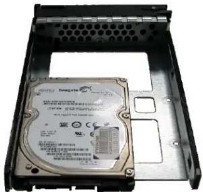
natural_image
Internal view of a hard disk drive housing (no visible text or labels)d. Install the mounting screws on the bottom part to secure the drive in the disk tray.
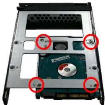
natural_image
Internal view of a computer hard drive showing internal components and mounting holes (no text or symbols visible)Tray Hole W
e. Slide the tray into a slot.
f. Close the lever handle until you hear the latch click into place.
- Chapter 1 Introduction....5
- Chapter 2 Installation....7
- Preface
- About this manual
- NOTES:
- IMPORTANT!
- WARNING!
- CAUTION:
- Copyright
- Trademarks
- Changes
- Before You Begin
- Safety Guidelines
- Upon receiving of the product:
- Upon installing of the product:
- Packaging, Shipment and Delivery
- Chapter 1 Introduction
- Key Features
- Technical Specifications
- Chapter 2 Installation
- Packaging, Shipment and Delivery
- Unpacking the NAS System
- Identifying Parts of the NAS System
- Front View
- HDD Status LEDs
- Fan Fail LED
- Lock Indicator
- Front Panel
- Rear View
- LCD Menu Diagram
- Getting Started with the NAS System
- NAS Hardware Setup
- Installing Hard Drives
- Installing 3.5" Disk in a Disk Tray
- Installing 2.5" Disk in a Disk Tray
Brand : Rocstor
Model : Rocsecure NE52
Category : NAS