
MEP 191 XN - Coffee machine Meireles - Free user manual and instructions
Find the device manual for free MEP 191 XN Meireles in PDF.

| Product Type | Espresso and filter coffee machine |
| Brand | Meireles |
| Model | MEP 191 XN |
| Dimensions (W x D x H) | 25 x 30 x 35 cm |
| Weight | 4.5 kg |
| Power | 1000 W |
| Voltage | 220-240 V ~ 50/60 Hz |
| Water Tank Capacity | 1.2 L |
| Bean Hopper Capacity | 200 g |
| Pump Pressure | 15 bar |
| Functions | Espresso, long coffee, steam function for milk frothing, hot water dispenser |
| Control Type | Electronic buttons with rotary dial |
| Milk System | Pannarello steam wand |
| Grinder | Built-in ceramic burr grinder |
| Grind Settings | 30 levels of adjustment |
| Water Filter | Removable water softener filter included |
| Cup Warmer | Passive cup warming tray on top |
| Auto Shut-Off | Yes, after 30 minutes of inactivity |
| Descaling Indicator | Yes, LED indicator |
| Cleaning | Removable drip tray and brew group; cleanable steam nozzle |
| Material | Stainless steel body and control panel |
| Security | Automatic pressure safety valve, boil-dry protection |
| Spare Parts | Available separately: brew group, water filter, seals, steam wand tip |
| Manual Languages | EN, PT |
Frequently Asked Questions - MEP 191 XN Meireles
User questions about MEP 191 XN Meireles
0 question about this device. Answer the ones you know or ask your own.
Ask a new question about this device
Download the instructions for your Coffee machine in PDF format for free! Find your manual MEP 191 XN - Meireles and take your electronic device back in hand. On this page are published all the documents necessary for the use of your device. MEP 191 XN by Meireles.
USER MANUAL MEP 191 XN Meireles
WARNINGS AND SAFETY PRECAUTIONS
AVISOS E PRECAUÇÕES DE SEGURANÇA

Risco de fogo!
Cleaning and protective maintenance
■ Surface may be damaged due to abrasive or hard cleaning materials. Never use abrasive or hard cleaning materials. Cleaning of the appliance surface Procure the proper cleaning and protective materials for your appliance from the authorized service. Note: Surface of the appliance and control units are delicate against scratches.
■ Clean the surfaces with a soft, damp cloth, dish soap or a less active glass cleaning material. Soften the dirt that is dried and stuck on the surface with a damp cloth. Do not rub!
■ It is not suitable to use dry clothes, scratchy sponges, materials that require rubbing, cleaning materials with sand, sodium carbonate, acids or chlorine and other active agents.
■ Clean the stainless steel surfaces on the machining direction only.
■ Do not use stainless steel cleaners and damp clothes for control elements.
Cleaning metal oil filters
Metallic oil filters used in the appliance traps the oil particles inside the humidity and vapour occurred in the kitchen. Clean the metal oil filters every three months approximately with a normal level of operation (1 to 2 hours per day).
■ Do not use over-active cleaning materials with acid or javel solution.
■ Clean the holding mechanisms of metal oil filters with a damp cloth while cleaning the metal oil filters.
■ You may wash the metal oil filters with a dishwasher or manually.
In the dishwasher:
Note: A light discoloration or change of color may occur when the filters are washed in a dishwasher. This does not affect the function of metal oil filter.
■ Do not wash heavily dirty metallic oil filters with other dishes.
■ Place the metallic oil filters on a dishwasher loosely or freely. Do not allow metal oil filters to be jammed.
Manual cleaning:
Note: You may use a special fat solvent for heavily soiled filters. You may buy this solvent from the online sales center.
You may operate this appliance with discharge air mode and circulated air mode.
Discharge air mode
Intake air is cleaned with oil filters and discharged through a pipe system.
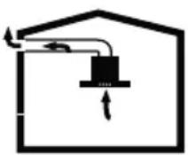
Note: Waste air shall not be discharged neither to an active smoke or waste air flue nor to a flue used for the ventilation of rooms where heating appliances are installed.
■ If you want to discharge the waste air to a non-active smoke or waste air flue, you shall take permission from an authorized chimney sweep.
■ If the waste air is discharged through an outside wall, a telescopic wall case shall be used.
Circulated air mode
Intake air is cleaned with oil filters and active carbon filter and returned back to the kitchen.

Note: You shall install an active carbon filter to trap particles that cause odor in the circulated air mode. For various possibilities to operate the appliance in circulated air mode, please refer to the manual or consult your authorized dealer. You may buy the accessories required for this procedure from relevant sales points, authorized dealers or from the online sales center. Refer to the end of operating manual for part numbers of the accessories.
FILTROS DE CARBONO ACTIVO
Figura 1
Figura 1a
Instalar o Exaustor na Parede
Figura 2
Instale a saída de plástico no topo da cabine do motor com parafusos 3,5 x 9,5. Figura 3
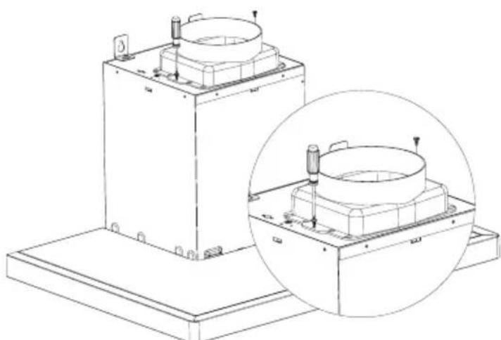
Figura 3
Figura 8
Figura 9
Figura 10
Figura 11
Figura 12
Figura 13
Figura 14
Operação
Ligar a Ventilação
Pressione no botão On/Off
Aumente no + e diminua no -
Ilumincação
“ C ” sign shall be displayed after 60 hours operation of the appliance.
This explanation applies to models with djt switch.
Desconecte o exausto
Figura 15
Figura 16
Substituir o LED Desconecte o aparelho.
Figura 17
Hood User Manual
MEP 261 X
MEP 291 X
MEP 361 X
MEP 391 X
MEP 191 XN
MEP 470 XN
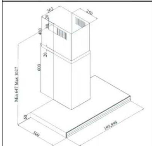
TECHNICAL DRAWINGS

MEP 470 XN
WARNINGS AND SAFETY PRECAUTIONS
*This appliance is intended for home usage.
*Operating voltage of your appliance is 220-240 Volt\~50 Hz.
*A grounded plug is installed on the power cord of your appliance. This cord shall always be plugged to a grounded outlet.
*Electrical installation shall be performed by a qualified electrician.
*Installation by unqualified persons may cause operation with low performance, damage to the appliance or accidents.
*Power cord shall not be crushed or smashed during installation. Do not route the power cord near the stoves; cord may melt and cause fire.
*Do not plug the appliance before installation of the appliance.
*Make sure that the plug is easily reachable in order to unplug the appliance in case of any danger.
*Do not touch the lamps of your appliance when they have operated for a long time. Lamps may burn your hand as they may be hot.
*Kitchen hoods are intended for home usage only with normal cooking. There is a risk of fault and it shall be void of warranty when it is operated for other purposes.
*Comply with the regulations of the authorities on the discharge of outlet air. (This warning does not apply to flueless applications.)
*Do not cook flammable food under the appliance.
*Operate your appliance after putting a pan, pot etc. on the stoves. Otherwise, high temperature may cause deformation of some parts of appliance.
*Turn off the stove before removing a pan, pot etc. from the stoves.
*Do not leave hot oil on a stove. Pots with hot oil inside may catch fire by itself.
*Oil may catch fire while you are frying etc.; watch for your curtains and linens.
*Ensure that the filters are replaced in time. Filters that are not replaced in time may cause a risk of fire due to the fat collected on them.
*Do not use filtering material that are not resistant to flames instead of filters.
*Do not operate your appliance without filters; do not remove the filters while the appliance is operated.
*In case of any fire, de-energize the hood and any other cooking devices. (De-energize the appliance by unplugging it.)
Your appliance may cause a risk of fire if the cleaning is not performed as per the specified periods.
*De-energize the appliance before any maintenance operations. (De-energize the appliance by unplugging it.)
*Negative pressure inside the room when the electric stove-top hood and other electrically powered
devices are operated simultaneously shall not exceed 4 Pa (4 X 10 bar).
*Any fuel- or gas-powered devices in the medium where your appliance shall be used, such as room heaters, shall be completely isolated from the volume where the exhaust of this appliance is placed, or the device shall be of hermetic type.
*Use pipes with a diameter of 150mm or 120 mm when you use flue connection for your appliance. Pipe connection shall be as short as possible and have minimum number of elbows.
*Do not allow your children to play with the appliance. Do not allow little children to use the appliance.
Use "MAX 6A" fuses on the hood installation for your safety.
*Keep package material away from children as they may pose a risk.
*If the power cord is damaged, it shall be replaced by the manufacturer or its authorized service or by an equally qualified technician to prevent any risky condition.
*In case of any fire, de-energize the hood and any other cooking devices, and cover the fire. Do not use water to put off the fire.
*When the cooking appliances are being operated, accessible parts may become hot.
*This appliance is not intended for use by persons (including children) with reduced physical, sensory or mental capabilities, or lack of experience and knowledge, unless they have been given supervised or instruction concerning use of the appliance by a responsible person for their safety.
*The distance between the appliance and the stoves should not be less than 65 cm in electric stoves and not less than 75 cm in gas and other types of stoves when the hood installation is completed.
*Exhaust of the hood shall not be connected to air ducts with other smoke.
*You should be careful when the appliance is operated with other appliances that use the air in the room and their fuel (e.g. heaters, water heaters that operate with gas, diesel fuel, coke or wood etc.) Because, hood may negatively effect the burning of the fuel as it exhausts the air inside the room.
*This warning does not apply to flueless applications.
APPLIANCE POSITION
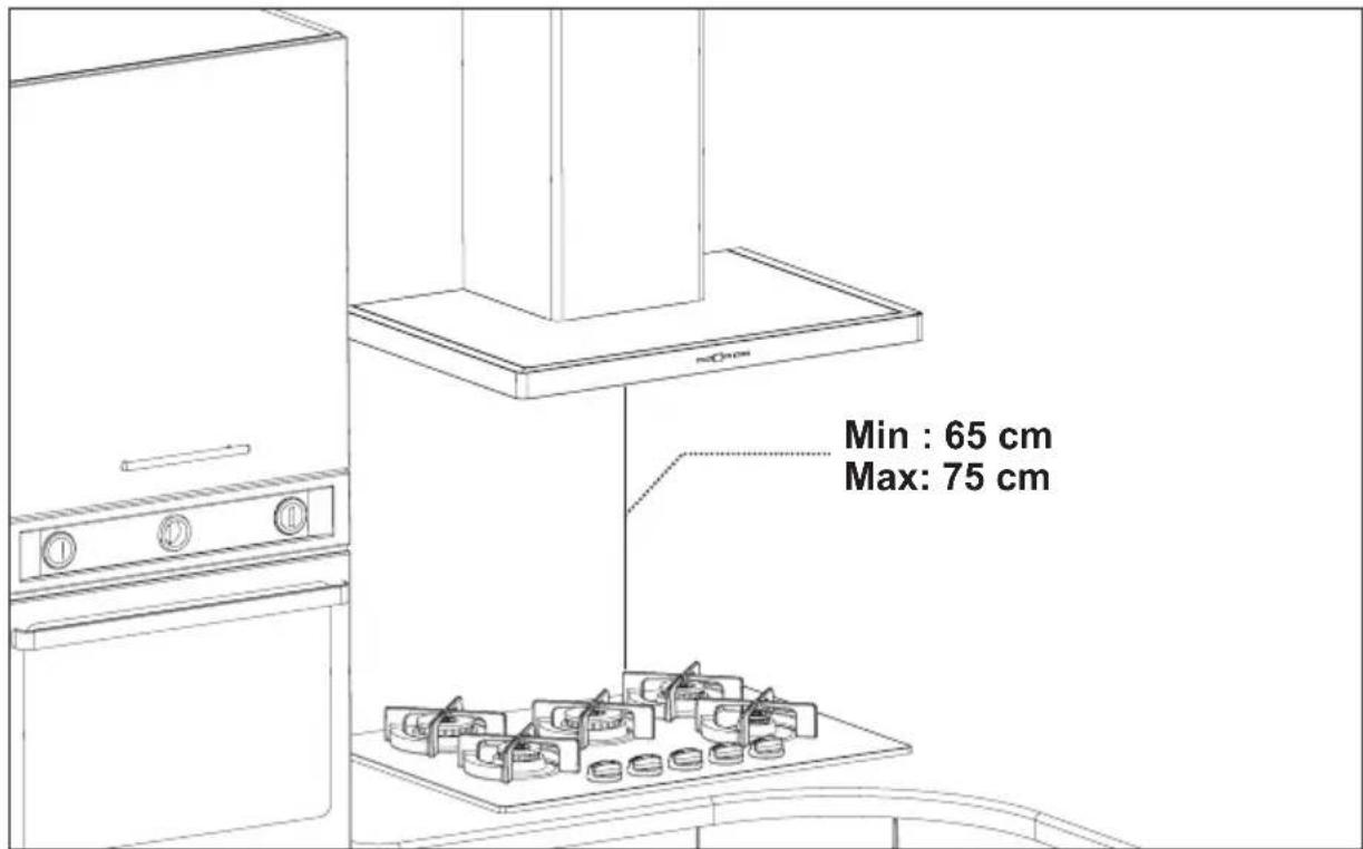
Figure 1
The distance between the appliance and the stoves should not be less than 65 cm in electric stoves and not less than 75 cm in gas and other types of stoves when the hood installation is completed. (Figure 1)

Installation Removing the Appliance from its Package:
* Check that your appliance is not deformed.
* Report the transport issues immediately to transport operator.
* Any faults encountered shall be reported to the dealer, too.
* Do not allow children to play with packing material!!!

Standard accessories
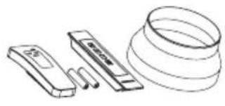
Optional accessories

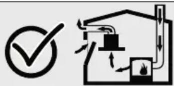
Vital risk, risk of poisoning!
There is a vital risk of being poisoned due to the combustion gases sucked back. Do not operate the appliance together with the air-circulated fire appliances unless adequate air intake is ensured.
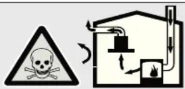
Air-circulated fire appliances (e.g. gas, oil, wood or coal stoves, water heaters etc.) take the combustion air from the installation place and discharge the waste air with a waste gas system (e.g. flue). With the hood being operated, air is taken from the kitchen and neighbouring rooms. A vacuum is generated if adequate air supply is not ensured. Poisonous gases are sucked back from the flue and discharge gas duct and re-entered to the house in such a condition.
■ Therefore, you shall always ensure that clean air intake is always adequate.

Risk of fire!
Due to the sparks fluttering around. Appliance is allowed to be installed over a heating appliance operated with solid fuel (e.g. wood or coal) only if there is a cover available that cannot be removed. Current building codes and regulations of the local power and gas companies shall be considered for the installation work.

Risk of electric shock!
Due to damaged connection cable. Do not kink or pinch the connection cable during installation..

Risk of injury!
There is a risk of injury due to the sharp edges during installation work. Always use protective gloves during installation work of the appliance.

Risk of injury!
Due to the dropping of the appliance. Always fix all safety bolts and safety covers properly.
Cleaning and protective maintenance
Risk of being burnt, Risk of electric shock!
Due to the appliance. Allow the appliance to cool before any cleaning or maintenance. Disconnect the fuse connection or remove the plug.
Caution!
■ There is a risk of damage due to the humidity ingress in electronic components. Do not clean the control elements with damp cloth.
■ Surface may be damaged due to improper cleaning. Clean the stainless steel surfaces on the brushing direction only. Do not use stainless steel cleaners for control elements.
■ Surface may be damaged due to abrasive or hard cleaning materials. Never use abrasive or hard cleaning materials.
Maintenance and repair
Risk of fire, risk of injury! Due to improper or out of rule repairs. Disconnect the fuse connection or remove the plug. Repair work shall always be performed by qualified personnel (electronic technicians).
Risk of injury!
In case of a fault or damage on the appliance, disconnect the fuse and remove the plug and call the authorized service.
Risk of fire, risk of injury!
Due to damaged connection cable. A damaged connection cable shall always be replaced by qualified personnel (electronic technicians).
Risk of being burnt, Risk of electric shock!
In case of a faulty bulb, disconnect the fuse connection or remove the plug. Replace the faulty bulbs immediately to prevent overloading of other bulbs (allow the bulbs to cool first).
Carbon Filter
Active carbon filters shall be used for filtering the air inside the room and giving it back to the room in environments without a flue connection. You may procure the active carbon filter from your authorized dealer or service. De-energize the appliance before replacing the carbon filter. Carbon filter shall be replaced every 3 to 5 months based on the frequency of operation as it is used in kitchens without flue outlet. Do not wash the carbon filter. Always have oil filters installed on the appliance without respect to the availability of the carbon filter. Do not operate your appliance without oil filter. Replacement of carbon filterThere are 2 carbon filters on the appliance. Rotate the carbon filter clockwise to install it.
Figure 1

Figure 1
Replacement of Aluminum Cartridge Carbon Filter
Press on the upper catch and pull towards yourself to remove the carbon filter. Figure 1a
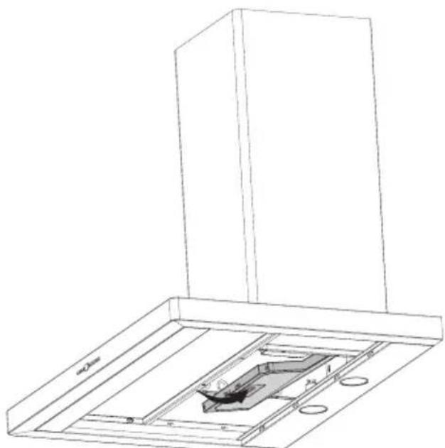
Figure 1a
Installation of the Appliance Installation of the suspension plate to the hood:
There are 2 (L) shaped suspension plates available in the installation accessories to suspend the appliance to the wall. These plates are supplied with a screw set to provide ease of installation. Screw these plates on M5 drive nuts on the cabinets with M5 x 40 screws before suspending the appliance. Figure 2
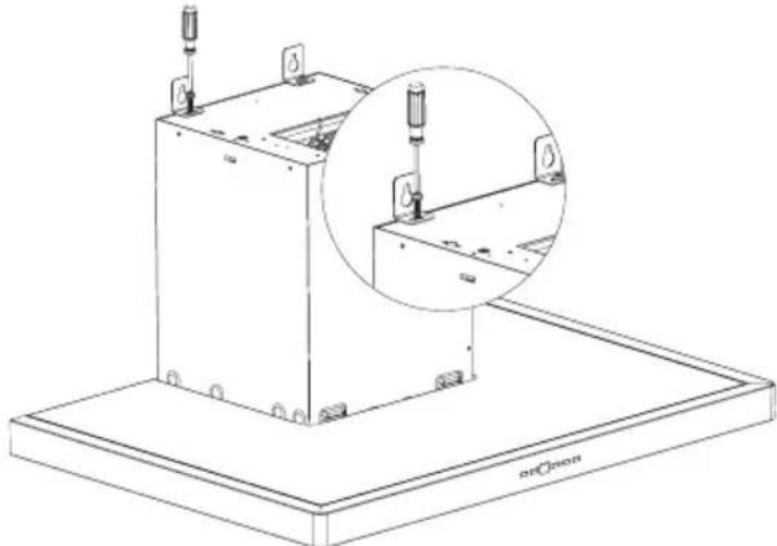
Figure 2
Installation of the plastic flue to the hood: Fix the plastic flue to the motor connection plate with a 3.5x9.5 screw. Figure 3
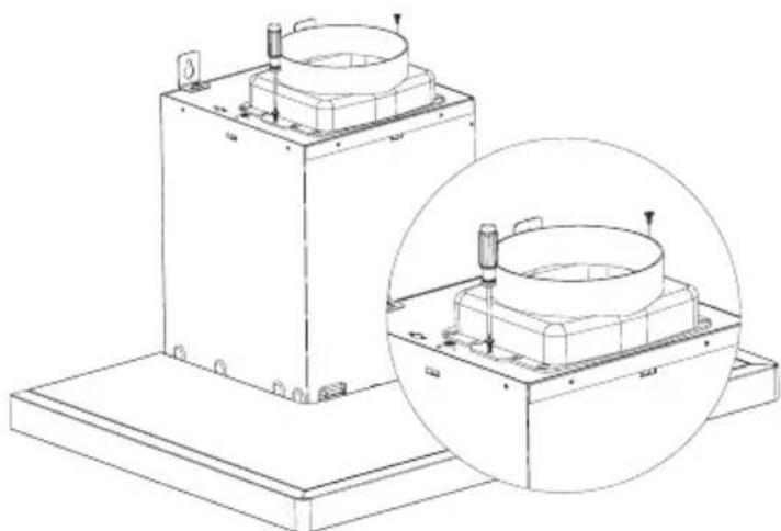
Figure 3
Drilling of Suspension Holes
Fix the installation template to the surface where the hood shall be suspended and drill holes in the points marked with (A,B,C) using a 8 mm drill bit.
Figure 4
Tap 10 mm plastic dowels to the holes you have drilled.
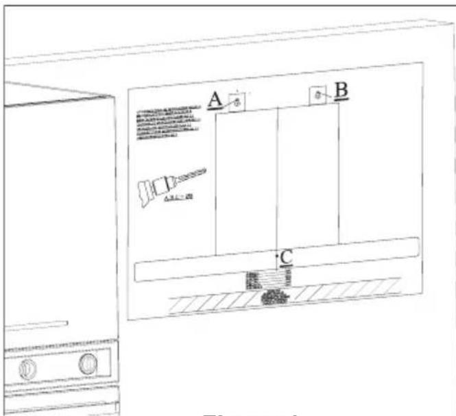
Figure 4
Drill the D, E points with a ∅ 6mm drill bit to screw the flue installation plate referring to the min. and max. heights of the appliance. Figure 5 Install 6 mm dowels to the holes you have drilled.
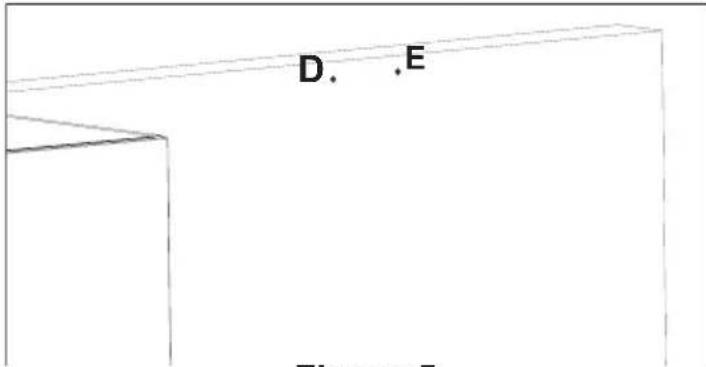
Figure 5
Tightening the suspension screws:
Tighten 5.5x60 suspension screws to ∅10 mm dowels (A, B) you have tapped on the wall. The distance between screw head and the wall shall be 5 mm. Figure 6
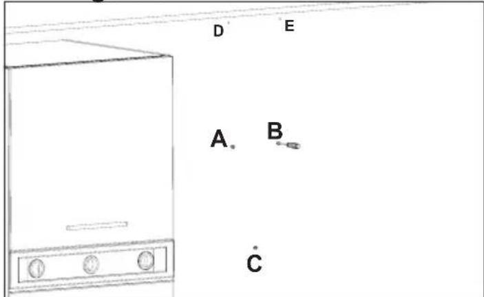
Figure 6
Tighten the flue installation plate to the ∅ 6 dowels you have tapped to the wall using the 3.9x22 screw supplied with your hood. Figure 7
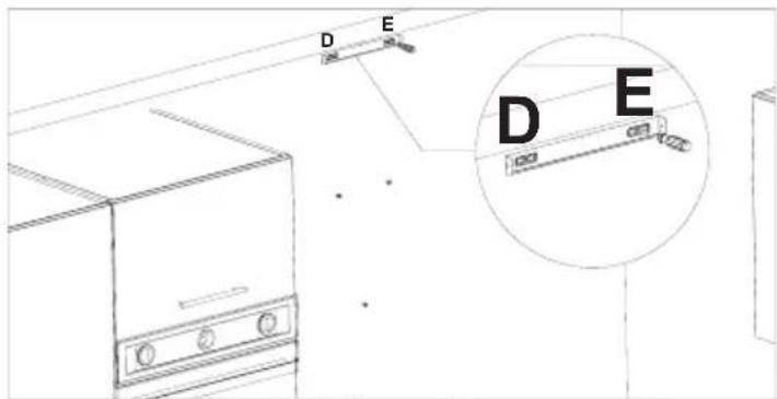
Figure 7
Suspending the Hood to the Wall:
Hold the hood from its body and suspend it to the wall on A and B points using the (L) plates you have fixed on the hood cabinet before. Figure 8

Figure 8
When the suspension procedure is completed, tighten the suspension screws installed to the wall in Fig. 6 with a screwdriver to prevent moving of the appliance. Figure 9

Figure 9
After you have fixed your hood completely, secure the body with a screw from the hole (C) inside the body to prevent it from moving. Figure 10
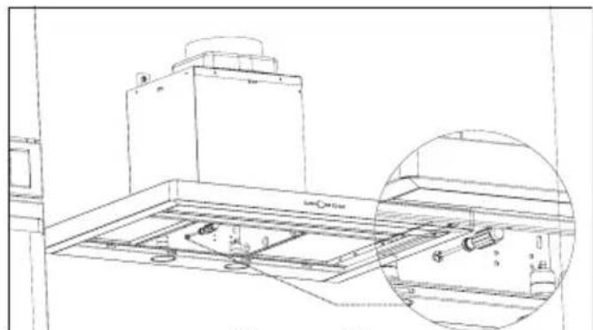
Figure 10
NOTE: If the hood seems skewed, adjust the alignment of the hood by loosening the M5 screws that the suspension plates on the top are installed to.
Figure 11

Figure 11
Installation of aluminum pipe: Install the flexible aluminum pipe to the plastic flue. Install the other end of the pipe to the flue hole on the wall.
Figure 12
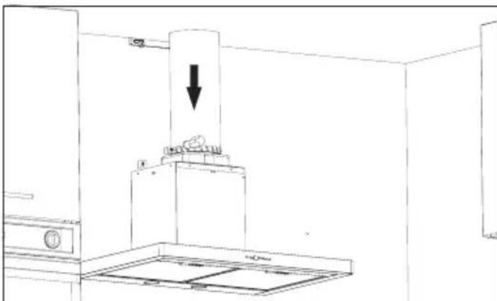
Figure 12
Avoid bends and elbows as much as possible as the bends and elbows in the aluminum pipe shall reduce the air suction power.
Engage the flues to the circumference of the body.
Figure 13
Appliance may have single flue on some model options. In this case, you may procure the inner flue suitable for your appliance from your authorized dealer.
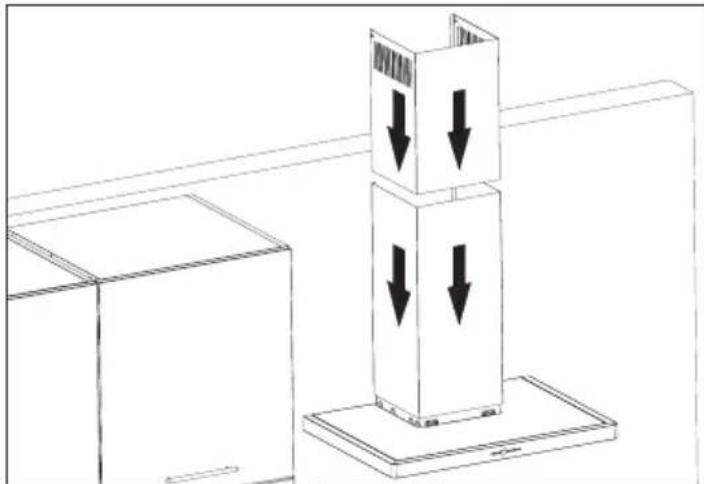
Figure 13
Tighten the inner flue to the flue installation plate secured on the wall from its upper external sides.
Figure 14
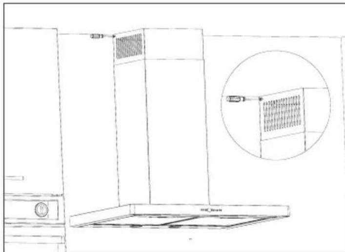
Figure 14
Operation
This manual applies to several appliance variants. Some specifications described here may not apply to your appliance.
Note: Turn on the hood when you start cooking and turn it off only after a few minutes later than you have finished cooking. The vapor inside the kitchen is removed most effectively in this way.
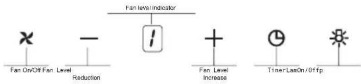
Control area Variant 1

Turning on the fan: Variant 1
Press the On/Off button.
Increase the fan level with +button or reduce the fan level with — button.
Illumination
You may turn on or off the illumination irrespective of the fan.
Timer:⑨ When you press this button for more than 2 seconds, a timer function of 15 minutes shall be activated, display shall signal when the timing function has started and motor shall stop automatically after 15 minutes.
Control area Variant 2

1- Press this button to turn on the appliance.
2- Press this button to operate the appliance in 3rd speed.
3- Press this button to operate the appliance in 3rd speed.
4- Press this button to operate the appliance in 3rd speed.
5- Press this button to turn on lamps of the appliance.

This explanation applies to models with push button switch.
Cleaning Periods for the Metal Filters:
Filters shall be cleaned every 2 to 3 weeks (as per frequency of operation) or when the "C" signal is shown on the display. After cleaning and installing the filters, press (①) button (when the appliance is turned off) to remove signal "C" for more than 3 seconds. "E" shall be indicated on the display and normal operation shall be resumed. If you want to resume operation without removing the "C" signal, active speed shall be displayed for 1 second when you press the (①) button and "C" signal shall be displayed again and the motor shall resume operation.

“ C ” sign shall be displayed after 60 hours operation of the appliance.

This explanation applies to models with djt switch.
BOOST INTENSIVE VENTILATION MODE
The model have been purchased has intensive ventilation mode with the intent of energy efficiency
Boost Mode: Product symbol (b) will be appearing on . the screen when the latest speed is in use The symbol b signifies boost mode (intensive ventilation) is active
Product will be working along 6 minutes with this mode and the symbol b will blink during this time. At the end of 6 minutes product will be passing to lower speed level automatically and will proceed working in this speed level
.Note: Timer feature is not used in boost mode
Replacement of Halogen Lamps

Disconnect the hood from mains
To replace halogen bulbs, press down from the rear side of the lamp socket and pull the lamp downwards, then rotate it a little clockwise and remove it downwards. Figure 15
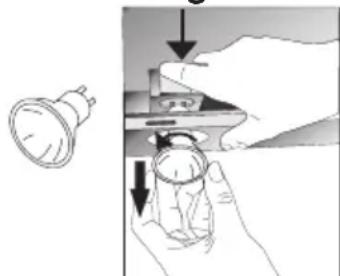
Figure 15
Replacement of Glow Bulbs
Disconnect the hood from mains. Remove the aluminum cartridge filter.
Remove the faulty bulb and replace with a new one with the same rating. (Lamps may burn your hand when they are hot, wait until they are cooled off.)
In order to replace the lamp, remove the glass cover on the lamp with an object that would not scratch the surface of the appliance as shown in Figure 16. Pull down and remove the faulty lamp and replace with a new one.
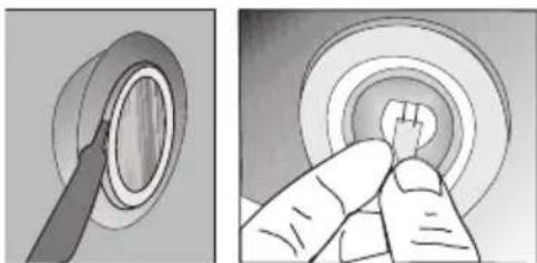
Figure 16
REPLACING THE LAMPS
Disconnect the hood from mains.
*Remove the power connection of LED lamp.
*Press on the lamp with your hand to remove the lamps.
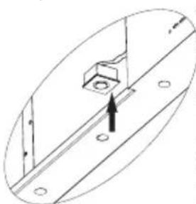
*Remove the adhesive tape around the lamp frame from the body plate.
* Before placing the new LED bulb, remove the protective foil on the frame and stick it on its position on the appliance body.
Replacement of Glow Bulbs
Disconnect the hood from mains.
Remove the aluminum cartridge filter. Remove the faulty bulb and replace with a new one with the same rating. (Lamps may burn your hand when they are hot, wait until they are cooled off.) Figure 17
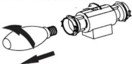
Figure 17
If the hood does not operate:
Before contacting the service:
Ensure that plug is installed on the outlet and that the power fuse in the installation is OK; do not perform any operations that may damage the appliance. Check your appliance as per Table 1 before contacting the service. Contact your dealer or nearest authorized service if the problem is resumed.
Before Contacting Authorized Dealer
- Ensure that the appliance is plugged in the outlet and that the fuses are OK.
If the Lighting Does Not Operate:
- Ensure that the appliance is plugged in the outlet and that the fuses are OK.
- Check the bulbs. Always unplug the appliance during this check. Tighten if the bulbs are loosened; you may replace them if they do not turn on although you have tightened them.
Possible Faults and Things To Do Before Contacting the Service:
A) If the appliance does not operate anyway:
- Check the fuse that the appliance is connected and main fuse of your home.
- Check whether the hood is plugged and whether the plug is fully seated on the outlet.
B) If the performance of the appliance is not enough or operates loudly:
- Is the outlet diameter of the flue adequate? (min. 120 mm).
- Are metal filters clean? Check it.
- Ensure that the carbon filters are not older than 6 months if you are using the hood flueless.
- Make sure that your kitchen is adequately ventilated to ensure the air flow.
Contact authorized service if the performance of your appliance does not still satisfy you.
| Check electric connection(Voltage of t electric network should be between 220-24 cooker hood should be connected togroun | Check motor switch (Motor switch shouldb on position) | Check motor switch (Motor switch shouldb on position) | Check aluminum filter(Aluminum Cassa Filter should be washed once a mont h normal conditions.) | Check lamps(Lamps shouldbe firm.) | Check outlet (Outlet should be open) | Check Carbon Filter (Carbon filter should replaced with a new one each 2-3 months at models w ith Car bon Fil to rat non conditions) | |
| Cooker-hood does not work | √ | √ | |||||
| Illumination Lamp does not work | √ | √ | √ | ||||
| Cooker-hoods air suction is weak | √ | √ | √ | ||||
| Cooker-hood does not direct air out (at places without chimney) | √ | √ |
Table 1
TECHNICALSPECIFICATIONS
| Feeding Voltage | 220-2 0 V 50Hz4 |
| Motor Isolation Class | F |
| Isolation Class | CLASS I |

- WARNINGS AND SAFETY PRECAUTIONS
- AVISOS E PRECAUÇÕES DE SEGURANÇA
- RISCO DE FOGO
- CLEANING AND PROTECTIVE MAINTENANCE
- DISCHARGE AIR MODE
- FILTROS DE CARBONO ACTIVO
- INSTALAR O EXAUSTOR NA PAREDE
- OPERAÇÃO
- LIGAR A VENTILAÇÃO
- ILUMINCAÇÃO
- DESCONECTE O EXAUSTO
- SUBSTITUIR O LED DESCONECTE O APARELHO
- HOOD USER MANUAL
- TECHNICAL DRAWINGS
- INSTALLATION REMOVING THE APPLIANCE FROM ITS PACKAGE
- VITAL RISK, RISK OF POISONING
- RISK OF FIRE
- RISK OF ELECTRIC SHOCK
- RISK OF INJURY
- RISK OF BEING BURNT, RISK OF ELECTRIC SHOCK
- CAUTION
- MAINTENANCE AND REPAIR
- RISK OF FIRE, RISK OF INJURY
- CARBON FILTER
- REPLACEMENT OF ALUMINUM CARTRIDGE CARBON FILTER
- INSTALLATION OF THE APPLIANCE INSTALLATION OF THE SUSPENSION PLATE TO THE HOOD
- DRILLING OF SUSPENSION HOLES
- FIGURE 4
- TIGHTENING THE SUSPENSION SCREWS
- SUSPENDING THE HOOD TO THE WALL
- OPERATION
- TURNING ON THE FAN: VARIANT 1
- ILLUMINATION
- BOOST INTENSIVE VENTILATION MODE
- REPLACEMENT OF HALOGEN LAMPS
- REPLACEMENT OF GLOW BULBS
- REPLACING THE LAMPS
- IF THE HOOD DOES NOT OPERATE
- BEFORE CONTACTING AUTHORIZED DEALER
- IF THE LIGHTING DOES NOT OPERATE
- POSSIBLE FAULTS AND THINGS TO DO BEFORE CONTACTING THE SERVICE
- IF THE APPLIANCE DOES NOT OPERATE ANYWAY
- IF THE PERFORMANCE OF THE APPLIANCE IS NOT ENOUGH OR OPERATES LOUDLY
Brand : Meireles
Model : MEP 191 XN
Category : Coffee machine