
CSW08X08S - AV Switch Smart-AVI - Free user manual and instructions
Find the device manual for free CSW08X08S Smart-AVI in PDF.

| Product Type | 8x8 AV Matrix Switch |
| Brand | Smart-AVI |
| Model | CSW08X08S |
| Video Inputs | 8 x HDMI (or VGA/composite, adjust if known) |
| Video Outputs | 8 x HDMI |
| Audio Support | Embedded audio via HDMI; optional analog audio breakout |
| Control Interfaces | IR remote, RS-232, Ethernet (IP control) |
| Maximum Resolution | 1920 x 1080 (Full HD) or 4K@30Hz depending on model |
| Dimensions (W x H x D) | 43.2 x 4.4 x 20.3 cm (17 x 1.75 x 8 inches, rackmount) |
| Weight | 3.2 kg (7 lbs) |
| Power Supply | 100-240 VAC, 50/60 Hz, 30W max |
| Power Consumption | 25W typical |
| Operating Temperature | 0°C to 40°C (32°F to 104°F) |
| Storage Temperature | -20°C to 60°C (-4°F to 140°F) |
| Humidity | 10% to 90% non-condensing |
| Main Functions | Matrix switching, signal routing, EDID management, scaling |
| Maintenance | Keep dry, clean with soft cloth, avoid dust accumulation |
| Safety | Use grounded outlet, avoid overloading circuits, keep vents clear |
| Spare Parts / Repairability | Contact Smart-AVI support for replacement power supply or IR receiver |
| General Information | Rackmountable 1U, LED indicators for each input/output |
Frequently Asked Questions - CSW08X08S Smart-AVI
User questions about CSW08X08S Smart-AVI
0 question about this device. Answer the ones you know or ask your own.
Ask a new question about this device
Download the instructions for your AV Switch in PDF format for free! Find your manual CSW08X08S - Smart-AVI and take your electronic device back in hand. On this page are published all the documents necessary for the use of your device. CSW08X08S by Smart-AVI.
USER MANUAL CSW08X08S Smart-AVI
16-port HDTV CAT5 Matrix Switch with RS-232, IR, USB, and TCP/IP Control
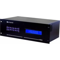
natural_image
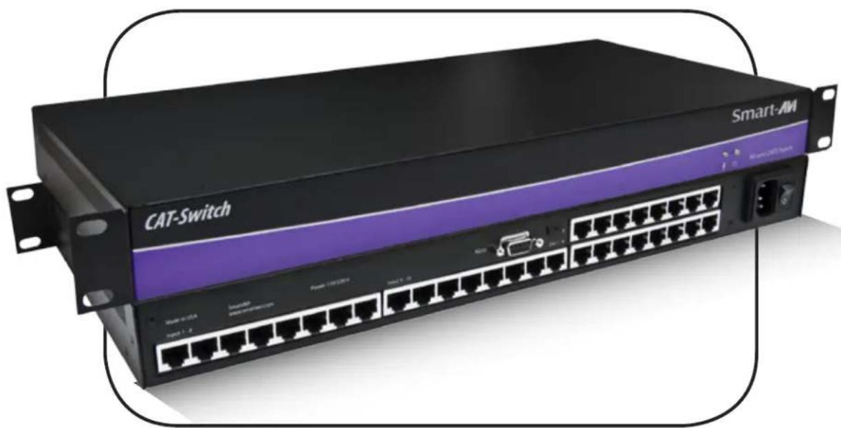
Exterior view of a Smart-AM network switch device with visible ports and connectors (no text or symbols on the device body beyond branding)For WUXGA, Component Video, Composite Video and S-Video with full stereo audio matrix switching Switch up to 16 remote devices to 16 remote displays located up to 1,000 feet away.
Introduction
CATSwitch routes audio and video signals from several different video sources out to multiple displays (projectors, monitors, etc.) and speakers via inexpensive Cat5/6 UTP cable.
CATSwitch is capable of connecting to as many as 16 video sources via transmitters and 16 video displays via receivers with a maximum extension of 1,000 feet between the transmitter and receiver units.
A single audio/video output can be routed to one or multiple destinations. Video is transmitted at a resolution of 1920 x 1200 to insure high resolution images. Buffered video outputs and analog delivery of stereo audio maintains optimum integrity throughout the system. Special remote boxes offer compatibility with Video Composite, UXGA, Component Video and S-Video.
Features
• Supports high resolution video up to 1920x1200
• High quality audio switching
• Infrared, RS232 and TCP/IP control
• PC Windows software control
• Integral UTP distribution
• 1U rackmounted chassis
• Uses easy to install, inexpensive CAT-5/5e/6/7/8
• Maximum extension of 1,000 feet (500m) between the local and remote units
• HDTV compatible. (720p, 1080i, 1080p)
• 300 MHz bandwidth
• Compatible with VGA, XGA, Sun, MAC and SGI
• Sync Format / Polarity Preservation
• Compatible with Line Level Stereo Audio Signals
• High ground loop immunity
• Built-in power surge and transient protection
- Designated trimmer in the remote unit to compensate for length
CATSwitch Rear
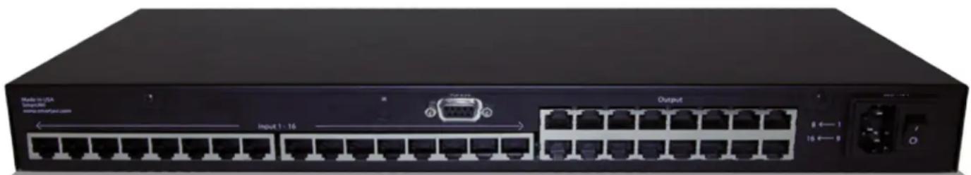
natural_image
Front view of a network switch device showing port, I/O ports, and status LEDs (no readable text or symbols beyond labels)Ordering Information
| Part Number | Description |
| CSW08X08S | CAT5 Matrix audio/video 8x8 matrix with RS232 control. Includes: [CSW08X08 (SM-CSW) and (CCPWR06US) or (CCPWR06EU)] |
| CSW16X08S | CAT5 Matrix audio/video 16x8 matrix with RS232 control. Includes: [CSW16X08 (SM-CSW) and (CCPWR06US) or (CCPWR06EU)] |
| CSW16X16S | CAT5 Matrix audio/video 16x16 matrix with RS232 control. Includes: [CSW16X16 (SM-CSW) and (CCPWR06US) or (CCPWR06EU)] |
| CSWP08X08S | CAT5 Matrix audio/video/IR and R232 8x8 matrix with RS232 control. Includes: [CSWP08X08 (SM-CSW) and (CCPWR06US) or (CCPWR06EU)] |
| CSWP16X08S | CAT5 Matrix audio/video/IR and R232 16x8 matrix with RS232 control. Includes: [CSWP16X08 (SM-CSW) and (CCPWR06US) or (CCPWR06EU)] |
| CSWP16X16S | CAT5 Matrix audio/video/IR and R232 16x16 matrix with RS232 control. Includes: [CSWP16X16 (SM-CSW) and (CCPWR06US) or (CCPWR06EU)] |
| Part Number | Receivers and Accessories |
| XTP-TXS | XTPRO UXGA/Audio/RS232/IR transmitter with Local Video . Includes:[ XTP-RX and (PS5VD1A)] |
| XTP-RXS | XTPRO UXGA/Audio/RS232/IR receiver with Dual Video Includes:[ XTP-RX and (PS5VD1A)] |
| XTP-RXLS | UXGA/Audio/RS232/IR Long Range receiver. Includes:[ XTP-RXL and (PS5VD1A)] |
| XTX-RXS | XT Xpress UXGA/Audio receiver. Includes:[ XTJ-RX and (PS5VD1A)] |
| XTJ-TXS | XT UXGA/Audio transmitter. Includes:[ XTJ-RX and (PS5VD1A)] |
| SM-TCPS | TCP/IP Control include SMTCP, (CCRS232MM ) and (PS5VD1A)] |
| SM-EYE | External infrared receiver. IR range of 10' to 30' |
| RMT-2 | Remote control device |
| XTP-RXXS | Xtreem UXGA/Audio/RS-232/IR CAT5 1699ft Receiver with Remote Control for Skew Setting. Includes: [XTP-RXX, SMRMT, & (PS5VD2A)] |
Technical Specifications
| VIDEO | |
| Bandwidth 250MHz | |
| Input Signal Level 1 Volt pk pk into 75R | |
| Output Impedance 100 Ohms | |
| Input Impedance 75 Ohms | |
| Connector RJ45 | |
| Format VGA/SVGA/XGA/WUXGA/RGB/Hv/RGsB | |
| AUDIO | |
| Bandwidth 20KHz | |
| Signal Level 0dB | |
| Output Impedance 100 Ohms | |
| Input Impedance 10K Ohms | |
| Connector RJ45 | |
| CONTROL | |
| RS232 Via Software @ 9600 bps | |
| IR Via Remote Control with IR-EYE Type 3 | |
| USB Via TCP/IP (optional) | |
| OTHER | |
| Power Internal 100-240 VAC | |
| Dimensions 17"W x 1.75"H (1U) x 8"D | |
| Weight 4 lbs. | |
| Approvals UL, CE, ROHS Compliant | |
| Operating Temp. 32-131°F (0-55 °C) | |
| Storage Temp. | -4-185 °F (-20-85 °C) |
| Humidity | Up to 95% |
Applications
• Corporate or Educational Presentations
• Financial (Remote Servers/User Control)
• Call Centers for Technical Support
• Industrial (Long-Range Workstation Isolation)
• Airport Installations (Air Traffic Control/Passenger Information)
• KVM Extension where Exceptional Quality of Signal is Crucial
• Medical (Remote Operation Away from Sensitive/Magnetic Equipment)
- Recording (for Large Studios where Editing/Mixing Stations are Compact and/or Require Complete Silence)
Application Diagram
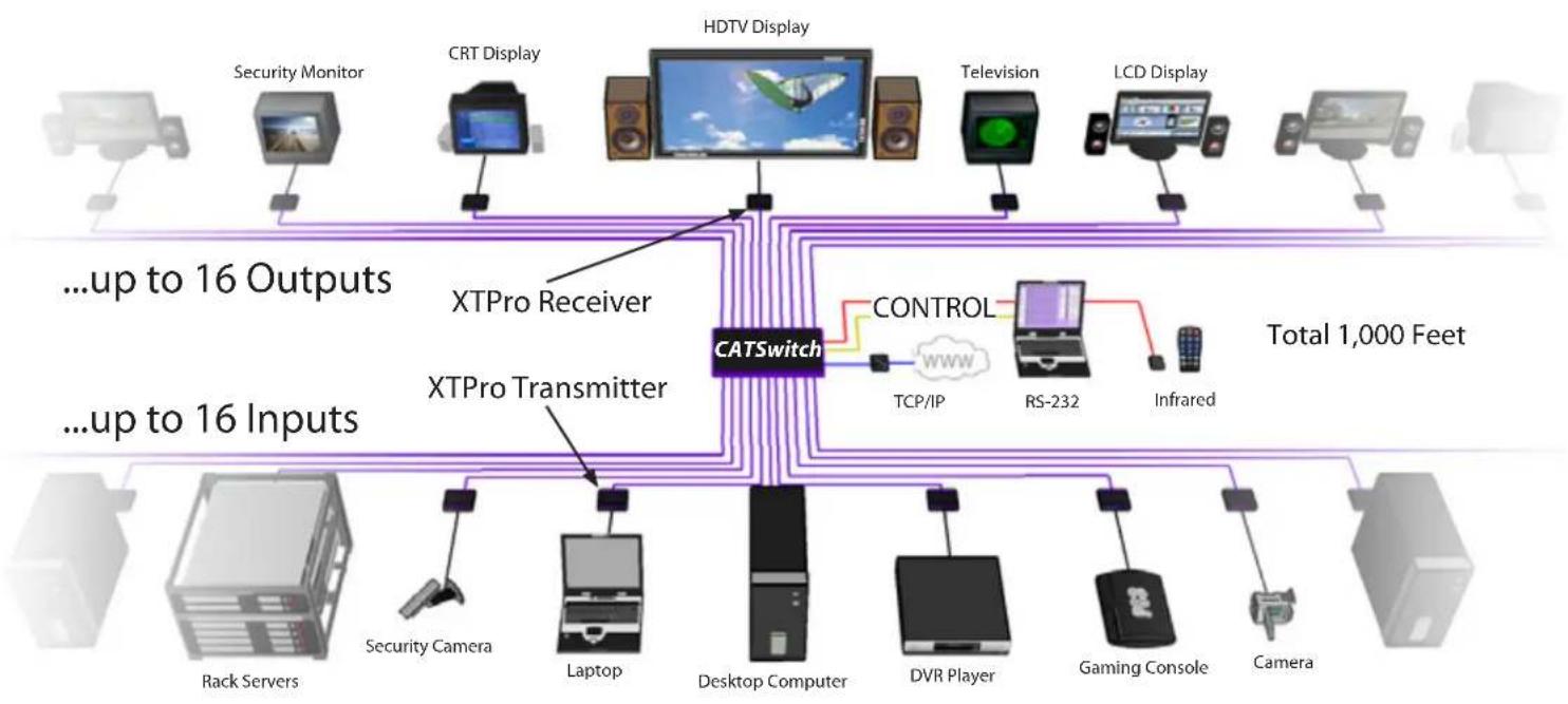
flowchart
graph TD
    subgraph Inputs
        A["Rack Servers"] --> B["Security Camera"]
        B --> C["Laptop"]
        C --> D["Desktop Computer"]
        D --> E["DVR Player"]
        E --> F["Gaming Console"]
        F --> G["Camera"]
        H["Security Monitor"] --> I["CRT Display"]
        I --> J["HDTV Display"]
        K["Television"] --> L["LCD Display"]
        M["Computer"] --> N["Controller"]
        O["Infrared"] --> P["RS-232"]
        Q["Total 1,000 Feet"] --> R["Central CATSwitch"]
    end

    subgraph Outputs
        S["...up to 16 Outputs"] --> T["XTPro Receiver"]
        U["...up to 16 Inputs"] --> V["XTPro Transmitter"]
    end

    style Inputs fill:#f9f,stroke:#333
    style Outputs fill:#ccf,stroke:#333
    style Outputs fill:#cfc,stroke:#333
    style Outputs fill:#fcc,stroke:#333
Installation
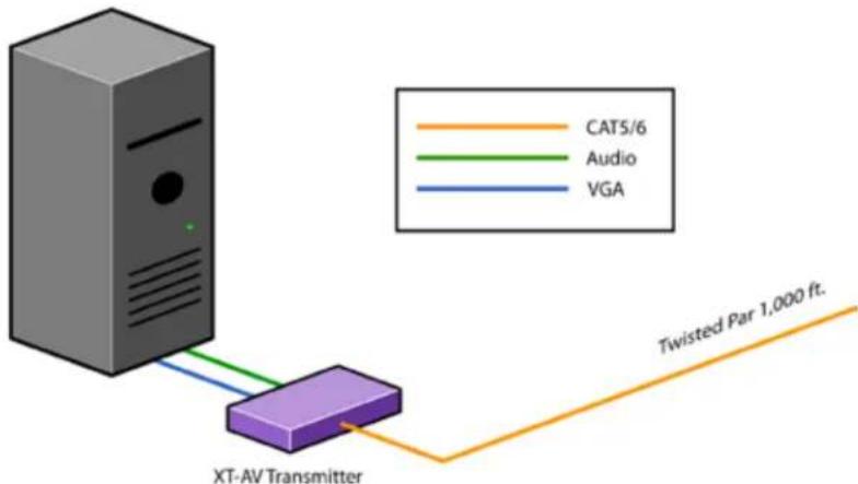
Connecting XTAV transmitter
Connecting The Transmitter
- Connect the output of the computer video card to the video input of the transmitter using the included male to male video cable.
- Connecttheoutputofthecomputeraudiocardtothe audio input of the transmitter using 3.5mm audio male to male audio cable.
- Connectexternalspeakerstothetransmitter'saudio out (Standard 3.5mm stereo miniplug).
- In the back of the unit connect the CAT5 cable that will connect to the receiver (XTAV-RX).
Connecting the XTAV receiver
Connecting The Receiver
- Connect CAT5 cable (coming from the transmitter) to the back of the receiver.
- Connect display monitors to the VGA out connector on the front of the receiver.
- Connect external speakers to the audio output connections on the front of the unit. (Standard 3.5mm stereo Miniplug)

flowchart
graph LR
    A["from CATSWITCH"] --> B["Twisted Par 1,000 ft."]
    B --> C["XT-AV Receiver"]
    C --> D["TV"]
    E["CAT5/6"] --> C
    F["Audio"] --> C
    G["VGA"] --> C
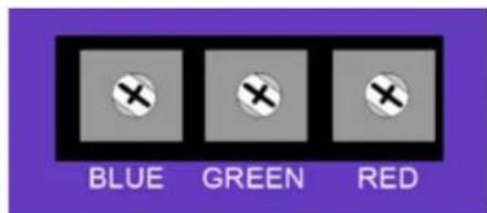
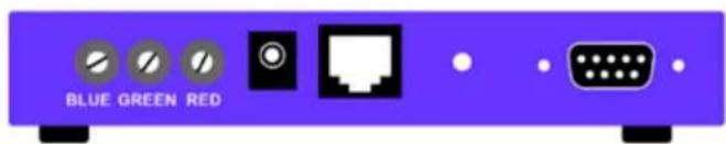
Adjusting and Tuning the Signal
In order to fine tune the signal, adjust the individual dials one at a time starting with GREEN, then BLUE, and lastly RED. As you turn the dials you will notice the colors slightly change as you increase or decrease the strength. All dials should be around the same distance
Installation (continued)
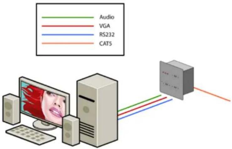
Connecting XTWALL Transmitter
Connecting The Transmitter
- Connect the output of the computer video card to the video input of the transmitter using the included male to male video cable.
- Connect the output of the computer audio card to the audio input of the transmitter using 3.5mm audio male to male audio cable.
- Connect local monitor to the VGA out of the transmitter.
- Connect external speakers to the transmitter's audio out (Standard 3.5mm stereo miniplug).
- In the back of the unit connect the CAT5 cable that will connect to the receiver (XTW-RX).
*NOTE: You can not use RS232 and IR at the same time.
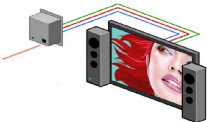
Connecting XTWALL Receiver
Connecting The Receiver
- Connect CAT5 cable (coming from the transmitter) to the back of the receiver.
- Connect 1-2 display monitors to the VGA out connectors on the front of the receiver.
- Connect 1-2 sets of external speakers to the audio output connections on the front of the unit. (Standard 3.5mm stereo Miniplug)
natural_image
Illustration of a TV with red flame streaming from a device to a screen (no text or symbols)Adjusting and Tuning the Signal
In order to fine tune the signal, adjust the individual dials one at a time starting with GREEN, then BLUE, and lastly RED. As you turn the dials you will notice the colors slightly change as you increase or decrease the strength. All dials should be around the same distance

Installation (continued)
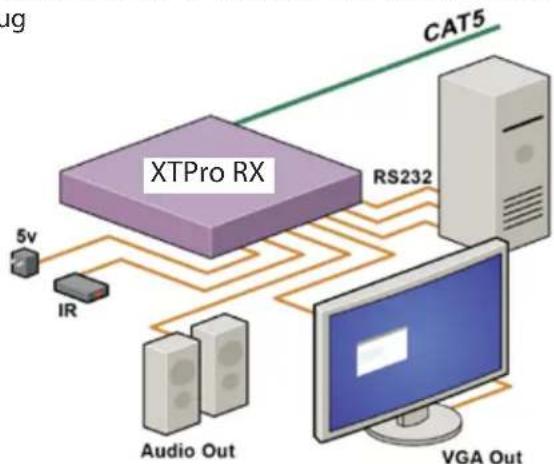
Connecting the XTPro transmitter
Connecting The Transmitter
- Connect the output of the computer video card to the video input of the transmitter using the included male to male video cable.
- Connect the output of the computer audio card to the audio input of the transmitter using 3.5mm audio male to male audio cable.
- Connect local monitor to the VGA out of the transmitter.
- Connect external speakers to the transmitter's audio out (Standard 3.5mm stereo miniplug).
- In the back of the unit connect the CAT5 cable that will connect to the receiver (XTPRO-RX). *NOTE: You can not use RS232 and IR at the same time.

flowchart
graph TD
    A["XTPro TX"] -->|5v| B["IR"]
    A -->|RS232| C["Computer"]
    D["Audio Out"] --> A
    E["VGA Out"] --> C
    F["CAT5"] --> A
    style A fill:#f9f,stroke:#333
    style B fill:#ccf,stroke:#333
    style C fill:#cfc,stroke:#333
    style D fill:#fcc,stroke:#333
    style E fill:#cff,stroke:#333
    style F fill:#ffc,stroke:#333
Connecting the XTPro receiver
Connecting The Receiver
- Connect CAT5 cable (coming from the transmitter) to the back of the receiver.
- Connect 1-2 display monitors to the VGA out connectors on the front of the receiver.
- Connect 1-2 sets of external speakers to the audio output connections on the front of the unit. (Standard 3.5mm stereo Miniplug
flowchart
graph TD
    A["XTPro RX"] -->|5v| B["IR"]
    A -->|RS232| C["Computer"]
    A -->|CAT5| D["Server"]
    B -->|Audio Out| C
    C -->|VGA Out| D
    style A fill:#f9f,stroke:#333
    style B fill:#ccf,stroke:#333
    style C fill:#cfc,stroke:#333
    style D fill:#fcc,stroke:#333
Adjusting and Tuning the Signal
In order to fine tune the signal, adjust the individual dials one at a time starting with GREEN, then BLUE, and lastly RED. As you turn the dials you will notice the colors slightly change as you increase or decrease the strength. All dials should be around the same distance.
Installation (continued)
Connecting the XTPro-XTREEM receiver
Connecting The Receiver
- Connect CAT5 cable (coming from the transmitter) to the back of the receiver.
- Connect a display monitor to the VGA out connectors on the front of the receiver.
- Connect a set of external speakers to the audio output connections on the front of the unit. (Standard 3.5mm stereo Miniplug

flowchart
graph TD
    A["XTPRO-XTREEM"] -->|5V| B["5V"]
    A -->|5V| C["IR"]
    A -->|5V| D["Audio Out"]
    A -->|5V| E["VGA Out"]
    A --> F["Computer"]
Adjusting and Tuning the Signal
In order to fine tune the signal, adjust the individual dials one at a time starting with GREEN, then BLUE, and lastly RED. As you turn the dials you will notice the colors slightly change as you increase or decrease the strength. All dials should be around the same distance.

Installation (continued)
Connecting the matrix
Now you are ready to connect the CATSwitch,
Connect all the cat5 coming from the transmitters to the inputs of the CATSwitch
Connect all the cat5 going to the receivers to the output
Connecting the the main unit, the CATSwitch
Make sure the unit is powered off before connecting all the cables
Connecting all the Transmitters
1 Locate the RJ45 jacks on the back of the CATSwitch,
2 Connect the CAT5 cable to the RJ45 and mark each cable with the number of the transmitter
3 REPEAT steps for all transmitters cables
Connecting all the receivers
1 Locate the RJ45 jacks on the back of the catswitch,
2 Connect the CAT5 cable to the RJ45 and mark each cable with the number of the receivers
3 REPEAT steps for all receivers cables
After all connection are made, you can turn on the catswitch, on the front on the units 2 leds will show normal operation of the unit
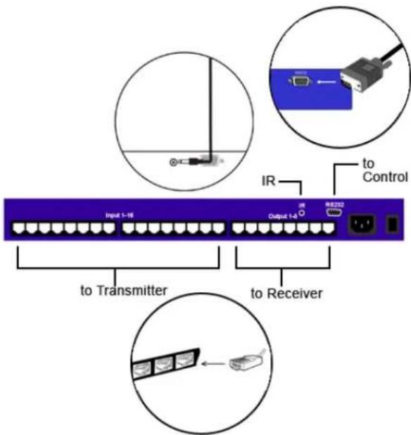
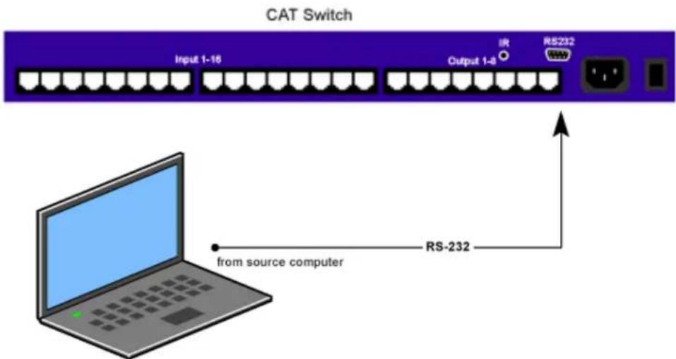
Connecting the Control Communication Cable: RS-232
Each unit can be controlled by a RS-232 port connected from the back of the chassis. The SmartControlPro software will be used to control the units.
- Connect the RS-232 cable the control computer by connecting the female RS-232 connector into the male RS-232 connector of the PC. Turn the side screws so that it does not accidentally become disconnected
- Connect RS-232 cable connector to the male RS-232 connector on the back of the chassis.
Installation (continued)
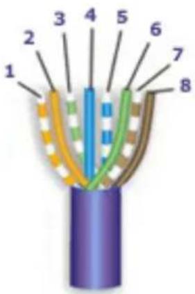
CAT5 Preparation
The CATSwitch is a point to point video extender/switcher. The system does not allow to connecting the Cat5 via hubs or any kind of switches that the point to point connection need be maintained. The 16 RJ45 ports on the front of the CATSwitch are output ports, providing connectivity to the XTPro or XT-AV receiver. This is a standard RJ45 connector, the CATSwitch can be connected via either CAT5, CAT5e or CAT6 cabling.
CAT5/5e/6 CABLE SPECIFICATIONS
| CONNECTOR | PAIR | PINS | |
| RJ-45 MALE[IMAGE] | RJ-45 FEMALE[IMAGE] | 1 | 1 & 2 |
| 2 | 3 & 6 | ||
| 3 | 4 & 5 | ||
| 4 | 7 & 8 | ||
| CAPACITANCE | 14 pf/ft (46.2 pf/m) | ||
| CONDUCTOR GAUGE | 24 AWG | ||
| IMPEDANCE | 100 +/- 15 ohms | ||
| SmartAVI Proprietary Connector | |||
| Pair | Color RJ45 Pin Description | ||
| 1 | White/Orange 1 | Video+Audio | |
| Orange 2 | |||
| 2 | White/Green 3 | Video+Audio | |
| Green 6 | |||
| 3 | Blue 4 | Video+Audio | |
| White/Blue 5 | |||
| 4 | White/Brown 7 | DATA RS232 and IR Bidirectional | |
| Brown 8 | |||
Software Operation
Find the Installation CD that came with your CATSWITCH unit. This CD has the SmartControlPro software that you will need in order to control the unit using a computer.
Insert the CD into your CD-ROM. On the CD you should see:
• SmartControl Pro Installer.exe
• SmartControl Pro Help File
• CATSWITCH Manual in PDF format
Double click SmartControlPro.exe in order to initiate software installation. Click Install. After installation has completed, click CLOSE.
In order to use the software, click on the START button>Programs>SmartControl Pro. There you should see a help file, the SmartControl Pro launcher as well as a shortcut to uninstall SmartControl Pro. Click on SmartControl Pro in order to launch the software.
When the software starts you will see a screen like this.

Advanced Configuration: If you have more than one Router installed you will want to check this box.
Router Type: Select "CATSWITCH"
A/V Split: Check this box if you need to route audio and video independently, regardless from which source they originated from. Leave unchecked if you want audio and video signals from the same input to remain together.
For example, if you wanted to route different video feeds to different locations but wanted all of them to have the same audio, you should check the box.
Software Operation (continued)
Inputs/Outputs: Enter the number of Inputs/Outputs your CATSWITCH has. For now we will assume that there are 16 inputs and 16 outputs.
Com Port: Select the appropriate com port that your computer is using to access the router.
Router Time out: By default this is 0 meaning the computer acknowledges commands almost instantly. Sometimes a computer takes longer to respond. This setting should be left at 0. If you need to change it, it should be no higher than 0.2.
After you have entered in the necessary information click OK. This will now take you to the Main Routing Window where you can route the different video/audio connections.
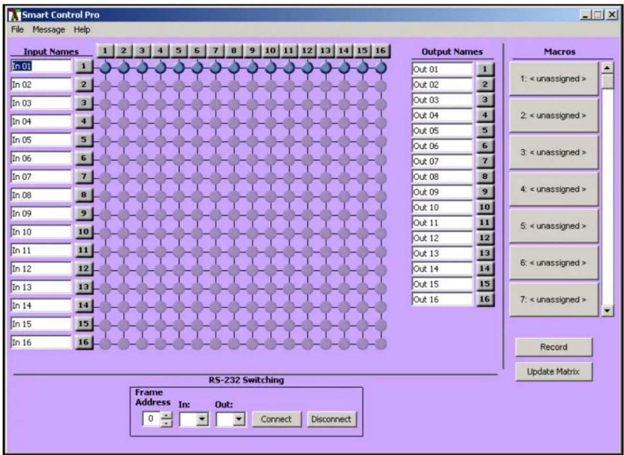
On this screen you will notice the input buttons running down the left side while the output buttons run across the top. They are each labeled 1 through 16.
Note: The three small colored buttons at the lower right labeled ALL, VIDEO, and AUDIO are not available if AV Split was not checked when you configured your router.
Software Operation (continued)
The Main Routing Window enables you to control the router(s) connections by means of the CATSWITCH panel, the button panel, or with pre-recorded routes called macros.
CATSWITCH Panel: This is probably the simplest way to route the connections. Simply click on the cross point itself. The input on the left will then be routed to the output above.
Note: Inputs can be routed to several different outputs, but each output can only have a single input at any one time. So you can have several connections horizontally but not vertically.

The Button Panel: These are the numbered buttons across the top and left sides. Click an output button on the top, and then click an input button on the left.
Options for using the Button Panel
• Output Options:
To select multiple outputs next to each other, click on one output, then hold the shift key down and click the last output. When the input is clicked, it is routed to all selected outputs.
To select multiple outputs individually, hold the control key down and click on any number of outputs. When the input is clicked, it is routed to all selected outputs.
- Input Options:
To route an input to all the outputs at once, hold the control key down and click on an input.
To leave the outputs selected after the route is made, hold the shift key down and click on an input.
Software Operation (continued)
Macros: This section of the window is used to save and play back macros. Macros store a set sequence of routes. To record a macro:
- Click on the Record button (last button shown above). A blinking "recording" message below this button will be displayed to indicate that all routes are being recorded.
- Select the desired cross points. (See CATSWITCH Routing for details on making these routes.) There is no limit on the number of routes you may record.
- If you click a macro button while in the record mode, the macro will be executed, and these routes will be added to the recording. This makes it possible to combine the routes of two or more macros into one bigger macro.
- When finished, click the "Save Macro" button. You will be instructed to then click on one of the macro buttons. Doing this will save the recorded routes to that button.
To cancel saving the macro, click the "Cancel Save" button.
-
To play back a macro, simply click on one of the 50 macro buttons. Use the scroll bar to bring any of these into view.
-
The macros are automatically saved in the current configuration file. They are also saved when you select the File/Save Configuration... menu.
To save macros in a separate file for a special purpose, select the File/Save Macros...menu.
Software Operation (continued)
Controlling with IR
Switching Ports with Remote Control
You have the option of controlling the CATSWITCH via Remote Control. The remote is used to control the CATSWITCH. The SM-EYE must be connected to the CATSWITCH (this is an optional connector not always available in all boxes) in order to interface the remote control with the matrix. The way the remote control the matrix is as follows:
Xx
When XX is the output, YY is the input
To change the routing of the signals,
For example, to set output 3 to input 2 press "0" + "3" + ENTER, then press "0" + "2" + ENTER. If a wrong button is pressed, the user must either press the ESC button or wait 5 seconds before restarting the sequence.

natural_image
Black electronic device with a cable and audio jack, no visible text or symbols
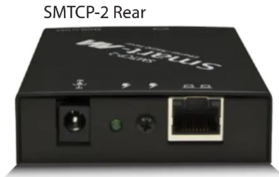
Controlling the CATSwitch with the SMTCP module
The SMTCP-2 is an RS-232 control module that allows most SmartAVI switching matrixes to be controlled remotely via HTTP or TELNET. Manage the switching functions of your matrix with ease from anywhere in the world. With the SMTCP-2 you can save up to 10 preset input/output configurations for easy access. TELNET access provides transparent command control of your matrix, perfect for use with automated third-party control software.
Features
• Supports HTTP and TELNET control
• 10/100 Ethernet Interface
• Up to 10 user-definable configurations
- Password Protected
• Up to 5 Users can Control the Matrices
• IP Configuration via TCP/IP and RS-232
• Flexible control of several types of matrixes
Applications
• Server Collocation
- Digital Signage
- Airports
- Dealer Rooms
- Control Rooms
• Audio/Visual Presentations
• Hotels/Resorts
- KVM Switches
Technical Specifications
| Power External 100-240 V | AC/5VDC2A @10W |
| Dimensions 2.8125"W x 1"H x 3.375"D | |
| Weight 0.5 lbs | |
| Approvals UL, CE, ROHS | Compliant |
| Operating Temp. 32-131°F (0-55 °C) | |
| Storage Temp. -4-185 °F (-20-85 °C) | |
| Humidity Up to 95% | |
Controlling the CATSwitch with the SMTCP module (continued)
Connecting to the SMTCP-2 for the first time
The first time you connect the SMTCP-2, you will need to perform the following steps to set the initial configuration. This includes establishing an HTTP connection and manually setting the IP address for the SMTCP-2.
- Power off all devices.

natural_image
3D rendering of a desktop computer tower with indicator lights and a green-labeled device (no text or symbols visible)COMPUTER
-
Use a female to male Straight-Through RS-232 (Serial) cable to connect the SMTCP-2 to the computer.
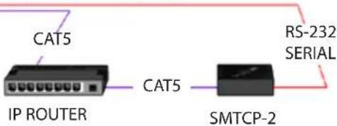
-
Use a CAT5 ethernet cable to connect the SMTCP-2 to a TCP/IP network via a network router or other network connection that has DHCP enabled. If your network does not support DHCP, please see page 22 of this manual for instructions.

natural_image
3D rendered diagram of a layered structure with no visible text or symbolsMATRIX SWITCH (NOT CONNECTED)
-
Power on the computer and run a terminal program such as Hyperterminal to open a serial connection to the SMTCP-2 using the standard 9600 baud, 8, N, 1 configuration.
-
Power on the SMTCP-2. When powered on, it will obtain an IP address automatically via DHCP from the network.
-
The IP information for the SMTCP-2 will be displayed on the terminal screen as follows:

addr:192.168.1.102
Mask:255.255.255.0
gtwy:192.168.1.1

NOTE: the above IP address is for demonstration purposes only. Actual results may be different.
- The IP address shown must be used to connect to the SMTCP via HTTP.
Controlling the CATSwitch with the SMTCP module (continued)
-
Open a web browser and navigate to the IP address that is indicated. You will be prompted to enter a username and password.
-
The default login (case sensitive) is as follows:
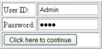
User ID: Admin
Password: Pass
- Once connected to the SMTCP-2, you will see the following menu of options:

- Matrix
- Frame Address
- Device Config
- Network Setting
- User Administration
For the initial setup, click the Network Setting button and manually assign an IP address to the SMTCP-2. This will assure
that the SMTCP-2 will always have the same IP address. Be sure to choose an address that will not conflict with any other devices on the network, and that the address is not in the range of the DHCP server.

natural_image
3D rendering of a desktop computer tower with indicator lights and drive bays (no text or symbols visible)COMPUTER
- Once you have manually assigned an IP address to the SMTCP-2, you may disconnect the Straight-Through RS-232 (Serial) cable from the computer
- Connect the SMTCP-2 to the matrix switch with a Cross RS-232 (Serial) cable.

It is also recommended that you set a password for the SMTCP-2 at this point. To set the password (and/or username), click on the User Administration button, enter the password and click Submit. This sets the password for the HTTP interface only.
Controlling the CATSwitch with the SMTCP module (continued)
Controlling the SMTCP-2 via HTTP
Once you have completed the Initial Setup for the SMTCP-2, you can now begin configuring it for your matrix. The following details the individual menu options in the web interface:
Matrix Menu

other
| Inputs: | Outputs: | 1 | 2 | 3 | 4 | 5 | 6 | 7 | 8 | |---|---|---|---|---|---|---|---|---|---| | 1 | ○ | ○ | ○ | ● | ● | ● | ○ | ○ | ○ | | this | ○ | ○ | ○ | ○ | ○ | ○ | ● | ● | ● | | is | ○ | ○ | ○ | ○ | ○ | ○ | ○ | ○ | ○ | | a | ○ | ○ | ○ | ○ | ○ | ○ | ○ | ○ | ○ | | test | ● | ○ | ○ | ○ | ○ | ○ | ○ | ○ | ○ | | 6 | ○ | ● | ○ | ○ | ○ | ○ | ○ | ○ | ○ | | 7 | ○ | ○ | ○ | ○ | ○ | ○ | ○ | ○ | ○ | | 8 | ○ | ○ | ○ | ○ | ○ | ○ | ○ | ○ | ○ | Matrix Preset This is a test 2 This is another 4 6 8 10 SAVE SAVE SAVE SAVE SAVE SAVEThe matrix menu allows you to set the crosspoints for the matrix. Crosspoints are used to route signals from the individual inputs to individual outputs. The output channels can only have one input, but each input can have several outputs.
Example shown in diagram:
Input 1 to Outputs 3,4,5
Input this to Outputs 6,7,8
Input test to Output 1
Input 6 to Output 2
The Matrix Preset option allows you to save and recall crosspoint configurations with the push of a button. To save a preset, simply configure your crosspoints and press the SAVE button next to the desired preset. To recall a preset, simply click on the button with its name. To edit the preset names, see the Device Config menu.
Frame Address Menu
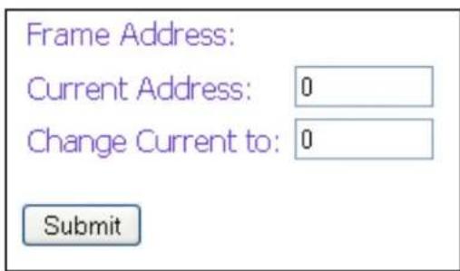
The frame address menu allows you to set the frame address of the current matrix switch. Frame addresses allow commands to be sent to different matrixes in series. For more information on the specific commands available, please see the instructions for your matrix switch.
Controlling the CATSwitch with the SMTCP module (continued)
Device Config Menu

The device configuration menu allows you to select the type of matrix you are using, specify the dimensions of the matrix, and assign names to the inputs, outputs and presets, reset the names and reset the system to factory defaults.
To begin, set the type of device you are using from the drop-down menu labeled Device Type and specify the Matrix Dimensions. After specifying the Matrix Dimensions, press the Submit button to make the changes.
Once the type of matrix is entered, you can assign names to each of your inputs, outputs and presets. The preset names are used in the Matrix Menu for quick storage and retrieval of matrix configurations. Leaving a preset blank will exclude it from the Matrix Menu.
Network Setting Menu
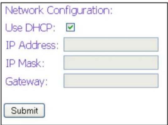
The network setting menu allows you to assign a static IP address to the SMTCP-2. It is recommended that you statically assign an IP address to avoid any future conflict or connectivity issues with DHCP.
Controlling the CATSwitch with the SMTCP module (continued)
User Administration Menu

The User Administration menu allows you to change the user name and password for the SMTCP-2. The default user name for the SMTCP-2 is Admin and the password is Pass. Once you modify the login information, press the Submit button to make the changes.
Controlling the SMTCP-2 via TELNET
Commands may be sent transparently to the matrix via a TELNET connection to the SMTCP-2. To use this function, use a telnet client such as Hyperterminal or PuTTY to connect to the IP address of the SMTCP-2. You will be prompted for a username and password - this will be the same as the login information via HTTP. Once logged in, the SMTCP-2 is ready to accept the standard RS-232 commands. For a list of the available commands, please see the user manual for the matrix you are using. Although the commands are not echoed to the client display, the commands are being issued to the matrix. Should you need commands to be echoed, please see the instructions for your TELNET client.
Upgrading the SMTCP-2
To upgrade the SMTCP-2 with the latest firmware, contact your sales representative to obtain the firmware upgrade file or visit the SMTCP-2 product page at www.smartavi.com. The version information is listed on the Main Menu. Once you have the file, use an FTP client, preferably TFTP, to navigate to the IP address of the SMTCP-2. To upload the file to the SMTCP-2, navigate to the /var/ directory, and upload the file firmware.img - IMPORTANT: the file MUST BE NAMED firmware.img for the upgrade to work properly. Again, the full path MUST BE /var/firmware.img. Once the file has been copied, restart (power off and power on) the SMTCP-2. Once restarted the firmware update will be installed. To verify the upgrade, see the version information listed on the Main Menu.

Controlling the CATSwitch with the SMTCP module (continued)
Connecting to the SMTCP-2 for the first time WITHOUT DHCP
The first time you connect the SMTCP-2, you will need to perform the following steps to set the initial configuration. This includes establishing an HTTP connection and manually setting the IP address for the SMTCP-2.

-
Power on the computer and run a terminal program such as Hyperterminal to open a serial connection to the SMTCP-2 using the standard 9600 baud, 8, N, 1, None Flow Control configuration.
-
While powering on the SMTCP-2, press and hold Shift-1 (exclamation) until a command prompt appears.
-
Press enter to show the network configuration help screen as follows:
Command:
E……
° Network Configuration help °
E……
Enter a command followed by optional parameters
Commands are SET DHCP INFO RESET and QUIT/SAVE
SET command allows you to change the network configuration: SI xxx.xxx.xxx.xxx = Set IP Address
(if IP address is not entered then DHCP is ENABLED)
SM xxx.xxx.xxx.xxx = Set IP Mask
SG xxx.xxx.xxx.xxx = Set Gateway Address
RN = Reset Network Params:
IPADDR = 192.168.0.2
IPMASK = 255.255.255.0
GATEWAY = 192.168.0.1
DHCP ON = Enable DHCP
DHCP OFF = Disable DHCP
INFO = Display network configuration
RESET = Factory reset
QUIT = Saves configuration and quits
SAVE = Same as QUITNOTE: the above IP address is for demonstration purposes only. Actual results may be different.
-
Follow the instructions to manually assign an IP address to the SMTCP-2.
-
See page 19 for instructions on how to connect to the SMTCP-2 via HTTP.
Technical Information
XTPRO SPECIFICATIONS
| Receiver with local monitor, Audio and IR/RS-232 support | |
| VGA Data | |
| Format RGBHV, RG | sB, YUV, Y/C, CVBS |
| Resolution | Up to 1900 x 1200 VGA, SVGA, XGA, SXGA |
| Connector Type HD | 15 socket |
| Audio | |
| Signal Type Stereo | unbalanced |
| Connector Type 3.5mm jack socket | |
| Infrared | |
| Signal Type 30 to 1 | 10Khz |
| Connector Type 3.5mm socket | |
| RS-232 | |
| Speed 2400 to 115Kbps | |
| Connector Type DB9 Male | |
| Power | |
| Requirements 5VDC @.5A | |
| Connector 2.1mm | DC jack (center +ve) |
| Physical | |
| Dimensions 135 x | 90 x 23mm (26 with pegs) |
| Weight .8 lbs or .36 kg | |
XTAV SPECIFICATIONS
| Receiver with Video and Audio support | |
| VGA Data | |
| Format RGBHV, RGsB, YUV, Y/C, CVBS | |
| Resolution | Up to 1900 x 1200 VGA, SVGA, XGA, SXGA |
| Connector type HD | 15 socket |
| Audio | |
| Signal Type Stereo unbalanced | |
| Connector 3.5mm jack socket | |
| Power | |
| Requirements 5VDC | @.5A |
| Connector 2.1mm DC jack (center +ve) | |
| Physical | |
| Dimensions 90 x 90 x 23mm (26 with pegs) | |
| Weight .6 lbs or .36 kg | |

natural_image
Two purple electronic devices with ports and connectors, no visible text or symbols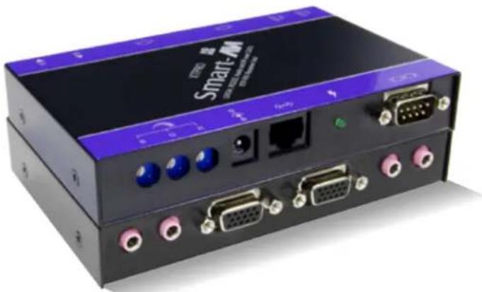
natural_image
Front view of a Smart-7-M network device with ports, connectors, and indicator lights (no readable text or symbols beyond branding)Technical Information (continued)
| XTProWALL | |
| VGA Data | |
| Fromat RGBHV, RGsB, YUV, Y/C, CVBS | |
| Resolution Up to 1900 x 1200, VGA, SVGA, XGA, SXGA) | |
| Connector Type HD 15 socket | |
| Audio | |
| Signal Type Stereo unbalanced | |
| Connector 3.5 mm jack socket | |
| RS232 | |
| DB9M | |
| TXD, RXD, Gnd. | |
| 9600 bps | |
| Power | |
| Requirements 5VDC@.5A | |
| Connector 2.1mm DC jack (center +ve) | |
| Physical | |
| Dimensions Face plate is 4.5" x 4.5 | |
| Weight 0.5 lbs | |
![Smart-AM XTW-Transmitter XTW-TX Audio Out IR In IR Out [IOI] Made in USA Smart-AM XTW-Receiver XTW-RX Audio Out IR In IR Out [IOI] Made in USA](/content/2026/06/1185999/images/b7201e178b5dc3e9a84cdb9f7361dbe50a9c28d5449c3b8d849f3e86716aa834.jpg)
RS-232 Specifications
How to properly create an RS-232 connection between a PC and most SmartAVI RS-232 compliant devices
Establish a connection to your RS-232 compliant device:
- Connect a straight through male to female RS-232 cable (shown on right) to the RS-232 connector on the PC.
- Connect the other end of the cable to the RS-232 compliant device.
- Power on the device.

natural_image
Coiled beige cable with two VGA connectors and a blue D-sub connector (no text or symbols visible)Male to Female Straight Cable (not provided)
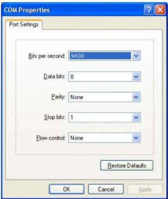
Hyperterminal Settings
Setting up the Terminal application:
- Open Hyperterminal on the PC. (or use the terminal client of your choice)
- Use the default settings to create a connection to the device (see settings on left). Settings MUST match those shown on the lower right.
- Be sure that Flow Control is None.
- The output of the device will be the same as the PC.
RS-232 Specifications (continued)
How to properly test an RS-232 connection between a PC and most SmartAVI RS-232 compliant devices
After you have established a connection to your device use the following commands:
1) To set a video crosspoint:
e.g. to set video input 3 to output 12 on a router with frame address "0" send the command: //F00M12I03<0x42>
2) To set RS-232 crosspoint:
3) To disconnect RS-232 crosspoint:
4) To set new frame address:
$$ / / \mathbf {F} \mathbf {x x M y y I z z} < \mathbf {C H K} > < \mathbf {C R} > $$
$$ / / \mathbf {F} \mathbf {x x} \mathbf {R} \mathbf {y y} \mathbf {I} \mathbf {z z} < \mathbf {C H K} > < \mathbf {C R} > $$
$$ / / \mathbf {F} \mathbf {x x D} \mathbf {y y I} \mathbf {z z} < \mathbf {C H K} > < \mathbf {C R} > $$
$$ / / \mathbf {F} _ {\text {xx}} \mathbf {F} _ {\text {nn}} < \mathbf {C} \mathbf {H} \mathbf {K} > < \mathbf {C} \mathbf {R} > $$
IMPORTANT
CALCULATING THE
RS-232 Specifications (continued)
How to properly test an RS-232 connection between a PC and most SmartAVI RS-232 compliant devices
RS-232 Commands continued:
5) To query crosspoints from PC:
//FxxU<CHK><CR>
- If all outputs are connected to input 1 then a 4x4 Matrix will respond with <0x80><0x80><0x80><0x80>
- The router will send back one byte for each output and the string ends with a
. The first byte sent is Output #1. In the example above, since there are 5 bytes total, we know that there are 4 outputs. - To calculate the input number, the router sends the input number with the 7^th bit set.
○ 0x80 = "1000 0000" → input 0
○ 0x81 = "1000 0001" → input 1
○ ...
○ 0x8F “1000 1111” → input 15
Comms Port Settings:
| Baud Rate | 9600 |
| Start Bits | 1 |
| Data Bits | 8 |
| Parity | None |
| Stop Bits | 1 |
Notes:
- When successful, commands #1-4 will acknowledge by sending the checksum with nibbles swapped &
o e.g. checksum of 0x24 acknowledges with <0x42>
RS-232 Specifications (continued)
How to properly test an RS-232 connection between a PC and most SmartAVI RS-232 compliant devices
The following are example commands for the first 8 inputs and 8 outputs. The hexadecimal values of the commands are also listed.
Operation Command
| input_1_output_1 | //F00M01101 | 2F 2F 46 30 30 4D 30 31 49 30 31 42 0D |
| input_2_output_1 | //F00M01102 | 2F 2F 46 30 30 4D 30 31 49 30 32 41 0D |
| input_3_output_1 | //F00M01103 | 2F 2F 46 30 30 4D 30 31 49 30 33 40 0D |
| input_4_output_1 | //F00M01104 | 2F 2F 46 30 30 4D 30 31 49 30 34 47 0D |
| input_5_output_1 | //F00M01105 | 2F 2F 46 30 30 4D 30 31 49 30 35 46 0D |
| input_6_output_1 | //F00M01106 | 2F 2F 46 30 30 4D 30 31 49 30 36 45 0D |
| input_7_output_1 | //F00M01107 | 2F 2F 46 30 30 4D 30 31 49 30 37 44 0D |
| input_8_output_1 | //F00M01108 | 2F 2F 46 30 30 4D 30 31 49 30 38 4B 0D |
| input_1_output_2 | //F00M02101 | 2F 2F 46 30 30 4D 30 32 49 30 31 41 0D |
| input_2_output_2 | //F00M02102 | 2F 2F 46 30 30 4D 30 32 49 30 32 42 0D |
| input_3_output_2 | //F00M02103 | 2F 2F 46 30 30 4D 30 32 49 30 33 43 0D |
| input_4_output_2 | //F00M02104 | 2F 2F 46 30 30 4D 30 32 49 30 34 44 0D |
| input_5_output_2 | //F00M02105 | 2F 2F 46 30 30 4D 30 32 49 30 35 45 0D |
| input_6_output_2 | //F00M02106 | 2F 2F 46 30 30 4D 30 32 49 30 36 46 0D |
| input_7_output_2 | //F00M02107 | 2F 2F 46 30 30 4D 30 32 49 30 37 47 0D |
| input_8_output_2 | //F00M02108 | 2F 2F 46 30 30 4D 30 32 49 30 38 48 0D |
| input_1_output_3 | //F00M03101 | 2F 2F 46 30 30 4D 30 33 49 30 31 40 0D |
| input_2_output_3 | //F00M03102 | 2F 2F 46 30 30 4D 30 33 49 30 32 43 0D |
| input_3_output_3 | //F00M03103 | 2F 2F 46 30 30 4D 30 33 49 30 33 42 0D |
| input_4_output_3 | //F00M03104 | 2F 2F 46 30 30 4D 30 33 49 30 34 45 0D |
| input_5_output_3 | //F00M03105 | 2F 2F 46 30 30 4D 30 33 49 30 35 44 0D |
| input_6_output_3 | //F00M03106 | 2F 2F 46 30 30 4D 30 33 49 30 36 47 0D |
| input_7_output_3 | //F00M03107 | 2F 2F 46 30 30 4D 30 33 49 30 37 46 0D |
| input_8_output_3 | //F00M03108 | 2F 2F 46 30 30 4D 30 33 49 30 38 49 0D |
| input_1_output_4 | //F00M04101 | 2F 2F 46 30 30 4D 30 34 49 30 31 47 0D |
| input_2_output_4 | //F00M04102 | 2F 2F 46 30 30 4D 30 34 49 30 32 44 0D |
| input_3_output_4 | //F00M04103 | 2F 2F 46 30 30 4D 30 34 49 30 33 45 0D |
| input_4_output_4 | //F00M04104 | 2F 2F 46 30 30 4D 30 34 49 30 34 42 0D |
| input_5_output_4 | //F00M04105 | 2F 2F 46 30 30 4D 30 34 49 30 35 43 0D |
| input_6_output_4 | //F00M04106 | 2F 2F 46 30 30 4D 30 34 49 30 36 40 0D |
| input_7_output_4 | //F00M04107 | 2F 2F 46 30 30 4D 30 34 49 30 37 41 0D |
| input_8_output_4 | //F00M04108 | 2F 2F 46 30 30 4D 30 34 49 30 38 4E 0D |
| input_1_output_5 | //F00M05101 | 2F 2F 46 30 30 4D 30 35 49 30 31 46 0D |
| input_2_output_5 | //F00M05102 | 2F 2F 46 30 30 4D 30 35 49 30 32 45 0D |
| input_3_output_5 | //F00M05103 | 2F 2F 46 30 30 4D 30 35 49 30 33 44 0D |
| input_4_output_5 | //F00M05104 | 2F 2F 46 30 30 4D 30 35 49 30 34 43 0D |
| input_5_output_5 | //F00M05105 | 2F 2F 46 30 30 4D 30 35 49 30 35 42 0D |
| input_6_output_5 | //F00M05106 | 2F 2F 46 30 30 4D 30 35 49 30 36 41 0D |
| input_7_output_5 | //F00M05107 | 2F 2F 46 30 30 4D 30 35 49 30 37 40 0D |
| input_8_output_5 | //F00M05108 | 2F 2F 46 30 30 4D 30 35 49 30 38 4F 0D |
Hexidecimal Value
RS-232 Specifications (continued)
How to properly test an RS-232 connection between a PC and most SmartAVI RS-232 compliant devices
input_1_output_6 // F 0 0 M 0 6 I 0 1 <CHK> <CR> 2F 2F 46 30 30 4D 30 36 49 30 31 45 0D
input_2_output_6 // F 0 0 M 0 6 I 0 2 <CHK> <CR> 2F 2F 46 30 30 4D 30 36 49 30 32 46 0D
input_3_output_6 // F 0 0 M 0 6 I 0 3 <CHK> <CR> 2F 2F 46 30 30 4D 30 36 49 30 33 47 0D
input_4_output_6 // F 0 0 M 0 6 I 0 4 <CHK> <CR> 2F 2F 46 30 30 4D 30 36 49 30 34 40 0D
input_5_output_6 // F 0 0 M 0 6 I 0 5 <CHK> <CR> 2F 2F 46 30 30 4D 30 36 49 30 35 41 0D
input_6_output_6 // F 0 0 M 0 6 I 0 6 <CHK> <CR> 2F 2F 46 30 30 4D 30 36 49 30 36 42 0D
input_7_output_6 // F 0 0 M 0 6 I 0 7 <CHK> <CR> 2F 2F 46 30 30 4D 30 36 49 30 37 43 0D
input_8_output_6 // F 0 0 M 0 6 I 0 8 <CHK> <CR> 2F 2F 46 30 30 4D 30 36 49 30 38 4F 0D
input_1_output_7 // F 0 0 M 0 7 I 0 1 <CHK> <CR> 2F 2F 46 30 30 4D 30 37 49 30 31 44 0D
input_2_output_7 // F 0 0 M 0 7 I 0 2 <CHK> <CR> 2F 2F 46 30 30 4D 30 37 49 30 32 47 0D
input_3_output_7 // F 0 0 M 0 7 I 0 3 <CHK> <CR> 2F 2F 46 30 30 4D 30 37 49 30 33 46 0D
input_4_output_7 // F 0 0 M 0 7 I 0  4 <CHK> <CR>    -2F
input_5_output_7 // F   O   O   M   O   T   O   T   O   S <CHK> <CR>    -2F
input_6_output_7 // F   O   O   M   O   T   O   T   O   S <CHK> <CR>    -2F
input_7_output_7 // F   O   O   M   O   T   O   T   O   T <CHK> <CR>    -2F
input_8_output_7 // F   O   O   M   O   T   O   T   O   S <CHK> <CR>    -2F
input_1_output_8 // F   O   O   M   O   T   O   T   O   T <CHK> <CR>    -2F
input_2_output_8 // F   O   O   M   O   T   O   T   O   T <CHK> <CR>    -2F
input_3_output_8 // F   O   O   M   O   T   O   T   O   T <CHK> <CR>    -2F
input_4_output_8 // F   O   O   M   O   T   O   T   O   T <CHK> <CR>    -2F
input_5_output_8 // F   O   O   M   O   T   O   T    S <CHK> <CR>    -2F
input_6_output_8 // F   O   O   M   O   T   O   T    S <CHK> <CR>    -2F
input_7_output_8 // F   O   O   M   O   T   O   T    S <CHK> <CR>    -2F
input_8_output_8 // F   O   O   M   O    T    O    T <CHK> <CR>    -2F
Query Current Matrix // F    O    O    U <CHK> <CR>    -2F
-2F
-2F
-46
-30
-30
-55
-13
-OD
RS-232 SPECIFICATION
How to properly test an RS-232 connection between a PC and most SmartAVI RS-232 compliant devices
RS-232 SPECIFICATIONS
| CONNECTOR | PIN | NAME | DESCRIPTION |
DB9 MALE - RECEIVE | 2 | RxD | Receive Data on DB9 Male |
| 3 | TxD | Transmit Data on DB9 Male | |
| 5 | SGND | Ground | |
DB9 FEMALE - TRANSMIT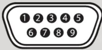 | 2 | TxD | Transmit Data on DB9 Female |
| 3 | RxD | Receive Data on DB9 Female | |
| 5 | SGND | Ground |
Limited Warranty Statement
A. Extent of limited warranty
-
SmartAVI Technologies, Inc. warrants to the end-user customers that the SmartAVI product specified above will be free from defects in materials and workmanship for the duration of 1 year, which duration begins on the date of purchase by the customer. Customer is responsible for maintaining proof of date of purchase.
-
SmartAVI limited warranty covers only those defects which arise as a result of normal use of the product, and do not apply to any:
a. Improper or inadequate maintenance or modifications
b. Operations outside product specifications
c. Mechanical abuse and exposure to severe conditions
-
If SmartAVI receives, during applicable warranty period, a notice of defect, SmartAVI will at its discretion replace or repair defective product. If SmartAVI is unable to replace or repair defective product covered by the SmartAVI warranty within reasonable period of time, SmartAVI shall refund the cost of the product.
-
SmartAVI shall have no obligation to repair, replace or refund unit until customer returns defective product to SmartAVI.
-
Any replacement product could be new or like new, provided that it has functionality at least equal to that of the product being replaced.
-
SmartAVI limited warranty is valid in any country where the covered product is distributed by SmartAVI.
B. Limitations of warranty
TO THE EXTENT ALLOWED BY LOCAL LAW, NEITHER SMARTAVI NOR ITS THIRD PARTY SUPPLIERS MAKE ANY OTHER WARRANTY OR CONDITION OF ANY KIND WHETHER EXPRESSED OR IMPLIED, WITH RESPECT TO THE SMARTAVI PRODUCT, AND SPECIFICALLY DISCLAIM IMPLIED WARRANTIES OR CONDITIONS OF MERCHANTABILITY, SATISFACTORY QUALITY, AND FITNESS FOR A PARTICULAR PURPOSE
C. Limitations of liability
To the extent allowed by local law the remedies provided in this warranty statement are the customers sole and exclusive remedies
TO THE EXTENT ALLOWED BY LOCAL LAW, EXCEPT FOR THE OBLIGATIONS SPECIFICALLY SET FORTH IN THIS WARRANTY STATEMENT, IN NO EVENT WILL SMARTAVI OR ITS THIRD PARTY SUPPLIERS BE LIABLE FOR DIRECT, INDIRECT, SPECIAL, INCIDENTAL, OR CONSEQUENTIAL DAMAGES WHETHER BASED ON CONTRACT, TORT OR ANY OTHER LEGAL THEORY AND WHETHER ADVISED OF THE POSSIBILITY OF SUCH DAMAGES.
D. Local law
To the extent that this warranty statement is inconsistent with local law, this warranty statement shall be considered modified to be consistent with such law.
© Copyright 2011 Smart-AVI, All Rights Reserved
NOTICE
The information contained in this document is subject to change without notice. Smart-AVI makes no warranty of any kind with regard to this material, including but not limited to, implied warranties of merchantability and fitness for any particular purpose.
Smart-AVI will not be liable for errors contained herein or for incidental or consequential damages in connection with the furnishing, performance or use of this material.
No part of this document may be photocopied, reproduced or translated into another language without prior written consent from Smart-AVI.
For more information, visit www.smartavi.com.
Smart-AM
SMART AUDIO VIDEO INNOVATION
SmartAVI, Inc. / Twitter: smartavi
11651 Vanowen St. North Hollywood, CA 91605
Tel: (818) 503-6200 Fax: (818) 503-6208
http://www.SmartAVI.com


- Introduction
- Features
- Applications
- Installation
- Connecting XTAV transmitter
- Connecting The Transmitter
- Connecting the XTAV receiver
- Connecting The Receiver
- Adjusting and Tuning the Signal
- Installation (continued)
- Connecting XTWALL Transmitter
- Connecting XTWALL Receiver
- Connecting the XTPro transmitter
- Connecting the XTPro receiver
- Connecting the XTPro-XTREEM receiver
- Connecting the the main unit, the CATSwitch
- Connecting all the Transmitters
- Connecting all the receivers
- Connecting the Control Communication Cable: RS-232
- CAT5 Preparation
- Software Operation
- Software Operation (continued)
- Options for using the Button Panel
- Controlling with IR
- Controlling the CATSwitch with the SMTCP module
- Controlling the CATSwitch with the SMTCP module (continued)
- Connecting to the SMTCP-2 for the first time
- Controlling the SMTCP-2 via HTTP
- Device Config Menu
- Network Setting Menu
- User Administration Menu
- Controlling the SMTCP-2 via TELNET
- Upgrading the SMTCP-2
- Connecting to the SMTCP-2 for the first time WITHOUT DHCP
- Technical Information
- Technical Information (continued)
- RS-232 Specifications
- Establish a connection to your RS-232 compliant device:
- Setting up the Terminal application:
- RS-232 Specifications (continued)
- After you have established a connection to your device use the following commands:
- IMPORTANT
- CALCULATING THE
- RS-232 Commands continued:
- 5) To query crosspoints from PC:
- Notes:
- The following are example commands for the first 8 inputs and 8 outputs. The hexadecimal values of the commands are also listed.
- RS-232 SPECIFICATION
- Limited Warranty Statement
- Extent of limited warranty
- Limitations of warranty
- Limitations of liability
- Local law
- © Copyright 2011 Smart-AVI, All Rights Reserved
- NOTICE
Brand : Smart-AVI
Model : CSW08X08S
Category : AV Switch