SuperChassis 742i-450 - Computer Case Supermicro - Free user manual and instructions
Find the device manual for free SuperChassis 742i-450 Supermicro in PDF.


| Product Type | Computer case (tower/rackmount) |
| Model | SuperChassis 742i-450 |
| Brand | Supermicro |
| Form Factor | 4U rackmount / tower convertible |
| Dimensions (H x W x D) | 7.0 x 17.2 x 25.6 inches (177 x 437 x 650 mm) |
| Weight | Approximately 30 lbs (13.6 kg) |
| Power Supply | 450W (single or redundant depending on config) |
| Supported Motherboard | E-ATX, ATX, and smaller |
| Drive Bays | 12 x 3.5" hot-swap SATA/SAS |
| Expansion Slots | 7 full-height, full-length |
| Cooling | 2 x 8cm rear exhaust fans, optional front fans |
| Front I/O | 2x USB 2.0, power/reset buttons, LED indicators |
| Security | Lockable front bezel, optional intrusion switch |
| Maintenance | Tool-less drive trays, removable motherboard tray |
| Cleaning | Use compressed air; avoid liquids on electronics |
| Spare Parts | Power supply, fan modules, drive trays available via Supermicro |
| Repairability | Modular design; user-replaceable fans, PSU, drives |
| Certifications | CE, FCC Class A, RoHS |
Frequently Asked Questions - SuperChassis 742i-450 Supermicro
User questions about SuperChassis 742i-450 Supermicro
0 question about this device. Answer the ones you know or ask your own.
Ask a new question about this device
Download the instructions for your Computer Case in PDF format for free! Find your manual SuperChassis 742i-450 - Supermicro and take your electronic device back in hand. On this page are published all the documents necessary for the use of your device. SuperChassis 742i-450 by Supermicro.
USER MANUAL SuperChassis 742i-450 Supermicro
natural_image
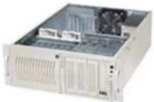
Exterior view of a server rack unit with visible internal components and ventilation slots (no text or labels)742S
natural_image
Exterior view of a beige server rack unit with ventilation grilles and internal cooling fans (no visible text or labels)742i
SC742 CHASSIS
USER'S GUIDE
1.0b
The information in this User's Guide has been carefully reviewed and is believed to be accurate. The vendor assumes no responsibility for any inaccuracies that may be contained in this document, makes no commitment to update or to keep current the information in this manual, or to notify any person or organization of the updates. Please Note: For the most up-to-date version of this manual, please see our web site at www.supermicro.com.
SUPERMICRO COMPUTER reserves the right to make changes to the product described in this manual at any time and without notice. This product, including software, if any, and documentation may not, in whole or in part, be copied, photocopied, reproduced, translated or reduced to any medium or machine without prior written consent.
IN NO EVENT WILL SUPERMICRO COMPUTER BE LIABLE FOR DIRECT, INDIRECT, SPECIAL, INCIDENTAL, OR CONSEQUENTIAL DAMAGES ARISING FROM THE USE OR INABILITY TO USE THIS PRODUCT OR DOCUMENTATION, EVEN IF ADVISED OF THE POSSIBILITY OF SUCH DAMAGES. IN PARTICULAR, THE VENDOR SHALL NOT HAVE LIABILITY FOR ANY HARDWARE, SOFTWARE, OR DATA STORED OR USED WITH THE PRODUCT, INCLUDING THE COSTS OF REPAIRING, REPLACING, INTEGRATING, INSTALLING OR RECOVERING SUCH HARDWARE, SOFTWARE, OR DATA.
Any
disputes
arising
manufacturer and customer shall be governed by the laws of Santa Clara County in the State of California, USA. The State of California, County of Santa Clara shall be the exclusive venue for the resolution of any such disputes. Supermicro's total liability for all claims will not exceed the price paid for the hardware product.
Unless you request and receive written permission from SUPER MICRO COMPUTER, you may not copy any part of this document.
Information in this document is subject to change without notice. Other products and companies referred to herein are trademarks or registered trademarks of their respective companies or mark holders.
Copyright © 2005 by SUPER MICRO COMPUTER INC.
All rights reserved.
Printed in the United States of America
Table of Contents
Chapter I: Safety Information and Technical Specifications .... 1-4
1-1. Safety Information
1-2. Technical Specifications.... 1-6
A.SUPER●742 SATA Back Panel 1-6
B. SCA742-E2 SCSI Dual Channel Back Panel (w/GEM318) 1-8
C. SCA 742 SCSI Single Channel Back Panel (w/GEM359) 1-10
D. SCSI (Super) GEM Driver Installation (*for the Windows OS) 1-12
Chapter 2: Installation Instructions ......2-1
Chapter 1-Safety
1-1 Safety Information

Electric Static Discharge (ESD) can damage electronic components. To prevent damage to your system board, it is important to handle it very carefully. The following measures are generally sufficient to protect your equipment from ESD.
Static-Sensitive Devices
- Use a grounded wrist strap designed to prevent static discharge.
- Touch a grounded metal object before removing the board from the antistatic bag.
- Handle the board by its edges only; do not touch its components, peripheral chips, memory modules or gold contacts.
- When handling chips or modules, avoid touching their pins.
- Put the motherboard and peripherals back into their antistatic bags when not in use.
- For grounding purposes, make sure your computer chassis provides excellent conductivity between the power supply, the case, the mounting fasteners and the motherboard.
- Use only the correct type of onboard CMOS battery as specified by the manufacturer. Do not install the onboard battery upside down to avoid possible explosion.
An important note to the user
All images and graphics shown in this manual were based upon the latest chassis Revision available at the time of publishing. The chassis you've received may or may not look exactly the same as the ones shown in this manual.

Before accessing the chassis:
- Turn off all peripheral devices connected to the SC742.
- Press the power button to power off the system.
- Unplug all power cords from the system or the wall outlets.
- Disconnect all the cables and label the cables for easy identification.
- Use a grounded wrist strap designed to prevent static discharge when handling components.
Removing the chassis covers:
After completing the above steps, you can remove the covers and install components/peripheral devices into the chassis as described in Chapter 2.
- Unlock and remove the screws and fasteners to remove the cover or components.
- Save all the screws and fasteners for later use. (If necessary, label these screws or fasteners for easy identification.)
- Follow the instruction given in Chapter 2 to remove the chassis covers.
Reinstalling the chassis covers:
To maintain proper system cooling and airflow, do not operate the system without installing all chassis covers back to the chassis. To reinstall the chassis covers, please follow the steps listed below:
- Make sure that all components and devices are securely fastened on the chassis and there are no loose parts/screws inside the chassis.
- Make sure that all cables are properly connected to the connectors and ports.
- Use the original screws or fasteners to install the covers to the chassis.
- Be sure to lock to the chassis or the system to prevent unauthorized access.
- For proper cooling, enclose the chassis with covers before operating the system.
Using the Chassis Handles properly:
The chassos handles are for sliding the chassis in and out of the racks only. Do not carry the chassis by the handles.
1-2 Technical Specifications
A. SUPER742 SATA Back Panel
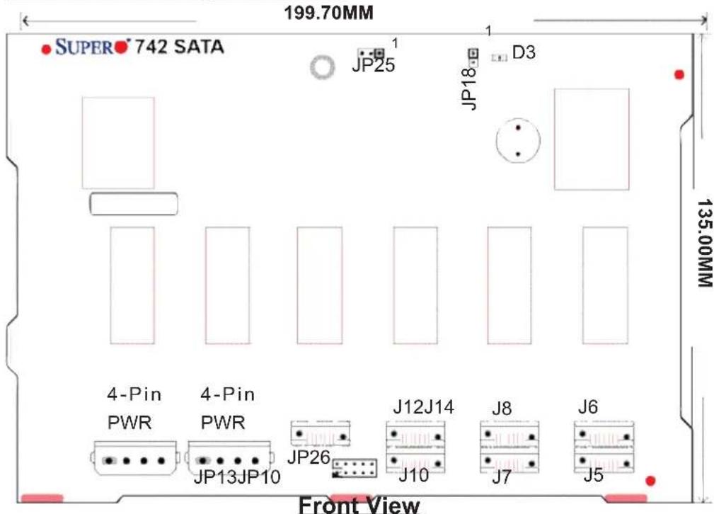
A-1 Connector/Jumper Locations
A-2 Connectors
D3: Overheat LED Indicator
J5: SATA #0 J6: SATA#1
J7: SATA #2 J8: SATA#3
J10: SATA #4 J12: SATA#5
J14: SATA #6
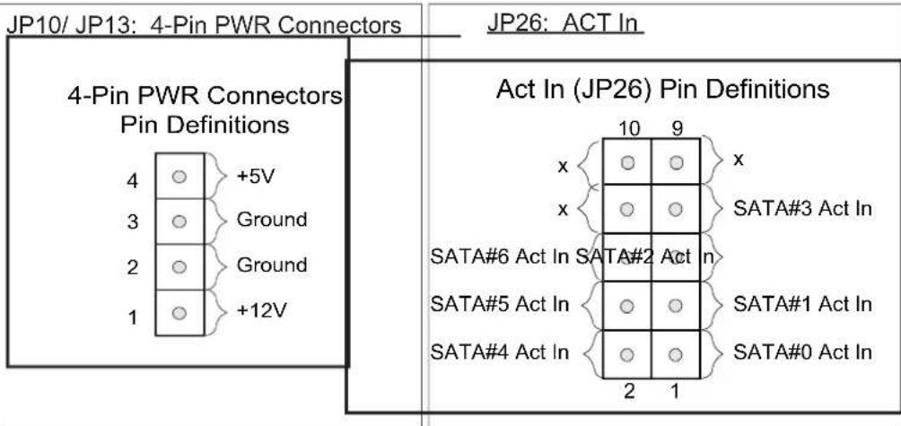
A-3 Jumpers
JP18: Buzzer Reset
| Buzzer Reset (JP18) | |
| Open | Disabled |
| Closed | Enabled (*Default) |
JP25: Overheat LED
| Overheat Temperature (JP25) | |
| Pins | Definition |
| Open | 45^ |
| 1-2 | 50^ |
| 2-3 | 55^ |
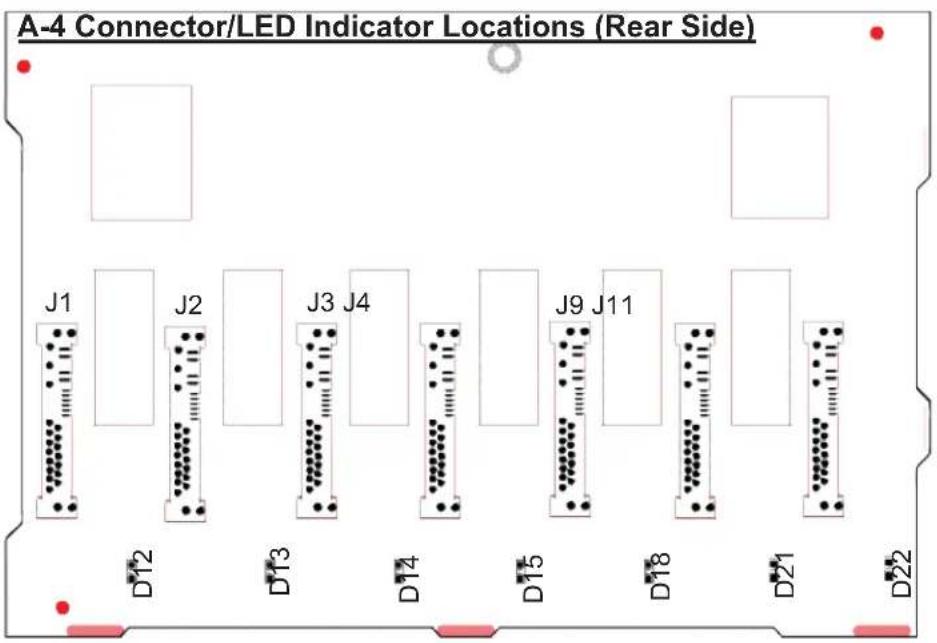
Rear View (*Not drawn to scale)
A-5 Activity LED Indicators
| Activity LED Indicators | |
| LED# | Drive# |
| D12 | SATA#0: Active |
| D13 | SATA#1: Active |
| D14 | SATA#2: Active |
| D15 | SATA#3: Active |
| D18 | SATA#4: Active |
| D21 | SATA#5: Active |
| D22 | SATA#6: Active |
B. SCA 74-E2 SCSI Dual Channel Back Panel (W/GEM318)
Front View (\*Not Drawn to Scale)
B-1 Connector/Jumper Locations
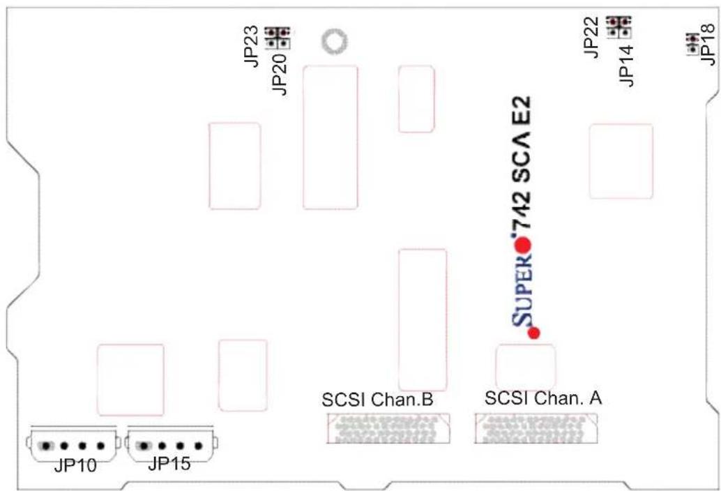
B-2 Connectors
JP10/JP15: 4-Pin PWR Connectors
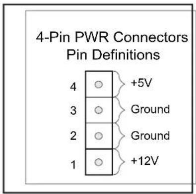
B-3 Jumpers
JP18: Buzzer Reset
| Buzzer Reset (JP18) | |
| Open | Disabled |
| Closed | Enabled (*Default) |
SCSI Channel B Jumpers
| Channel A Jumpers | |
| Jumpers | Definition |
| JP14 | Ch.A Delay Start |
| JP22 | Ch.A Remote Start |
| Channel B Jumpers | |
| Jumpers | Definition |
| JP20 | Ch.B Delay Start |
| JP23 | Ch.B Remote Start |
B-4 Connector/LED Indicator Locations (Rear)
Rear View (*Not drawn to scale)
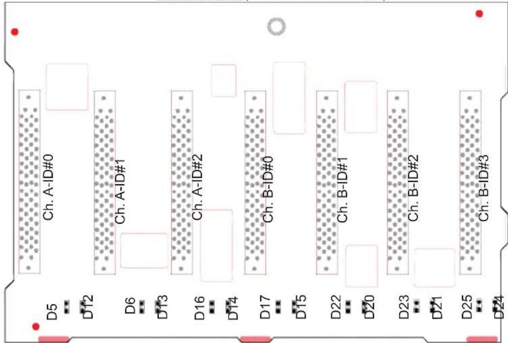
B-5 LED Indicators (Rear)
SCSI Drive Fail LED Indicators
| Drive Fail LED Indicators | ||
| LED# | Drive ID# | SCA# |
| D5 | Channel A-ID#0 | SCA 1: Fail |
| D6 | Channel A-ID#1 | SCA 2: Fail |
| D16 | Channel A-ID#2 | SCA 3: Fail |
| D17 | Channel B-ID#0 | SCA 4: Fail |
| D22 | Channel B-ID#1 | SCA 5: Fail |
| D23 | Channel B-ID#2 | SCA 6: Fail |
| D25 | Channel B-ID#3 | SCA 7: Fail |
SCSI Drive Activity LED Indicators
| Drive Activity LED Indicators | ||
| LED# | Drive ID# | SCA# |
| D12 | Channel A-ID#0 | SCA 1: Active |
| D13 | Channel A-ID#1 | SCA 2: Active |
| D14 | Channel A-ID#2 | SCA 3: Active |
| D15 | Channel B-ID#0 | SCA 4: Active |
| D20 | Channel B-ID#1 | SCA 5: Active |
| D21 | Channel B-ID#2 | SCA 6: Active |
| D24 | Channel B-ID#3 | SCA 7: Active |
C. SCA 742 SCSI Single Channel Back Panel (w/GEM359)
Front View (\*Not Drawn to Scale)
C-1 Connector/Jumper Locations
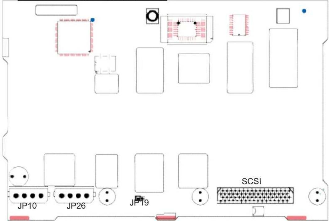
C-2 Connectors
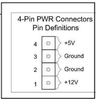
JP10/JP26: 4-Pin PWR Connectors
C-3 Jumpers
JP19: Buzzer Reset
| Buzzer Reset (JP19) | |
| Open | Disabled |
| Closed | Enabled (*Default) |
C-4 Connector/LED Indicator Locations (Rear)
Rear View (*Not drawn to scale)
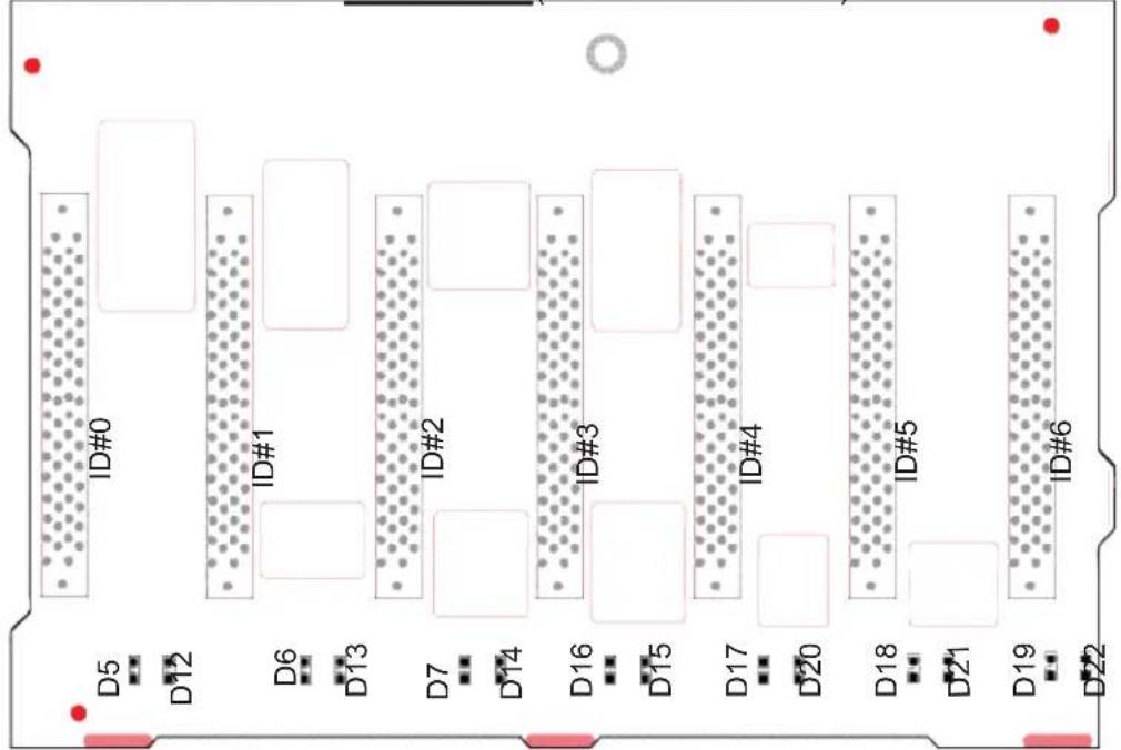
C-5 LED Indicators (Rear)
SCSI Drive Fail LED Indicators
| Drive Fail LED Indicators | ||
| LED# | Drive ID# | SCA# |
| D5 | ID#0 | SCA 1: Fail |
| D6 | ID#1 | SCA 2: Fail |
| D7 | ID#2 | SCA 3: Fail |
| D16 | ID#3 | SCA 4: Fail |
| D17 | ID#4 | SCA 5: Fail |
| D18 | ID#5 | SCA 6: Fail |
| D19 | ID#6 | SCA 7: Fail |
SCSI Drive Activity LED Indicators
| Drive Activity LED Indicators | ||
| LED# | Drive ID# | SCA# |
| D12 | ID#0 | SCA 1: Active |
| D13 | ID#1 | SCA 2: Active |
| D14 | ID#2 | SCA 3: Active |
| D15 | ID#3 | SCA 4: Active |
| D20 | ID#4 | SCA 5: Active |
| D21 | ID#5 | SCA 6: Active |
| D22 | ID#6 | SCA 7: Active |
D SCSI (Super) GEM Driver Installation (\*for the Windows OS)
(*Note: This driver is not necessary for other Operating Systems. If you have two SCA backplanes, you will need to install the driver twice.)
The driver is located on the Super Micro motherboard driver CD or is available for download from our FTP site: ftp://ftp.supermicro.com/driver/Qlogic/
Follow the procedure below to install this driver to your system.
Installing the driver:
1) Right click on "My Computer" and choose "Property".
2) Select "Hardware" tab and click on "Device Manager".
3) Open "Other Devices" or wherever "GEM318/GEM359" is on.
4) Right click on this device and choose "Property".
5) Click on "Driver" tab and choose "Update Driver".
6) Click "Next" 2 times, uncheck both "Floppy disk drives" and "CD-ROM drives". Then, select the item- "Specify a location," and choose "Next".
7) Click on "Browse" and choose D drive or wherever Supermicro Setup CD is in.
8) Choose "Qlogic" folder and click on "Open".
9) System will automatically detect GEM318/GEM359 and install the drive from this point on.
or,
1) Right click the "My Computer" icon on your desktop and choose Properties.
2) Click on the Hardware tab and click on "Device Manager" to bring up the list of system devices.
3) You may see one or two yellow question marks (?) that read QLogic GEM318/GEM359 SCSI Processor Device. Right click on these, and choose to uninstall. If two such question marks are present, uninstall both.
4) Click on Action tab and choose "Scan for Hardware Changes". The Hardware Wizard program should start up. Click "Next".
5) At the first prompt, choose "Display a list of known device drivers for the device so that I can choose a specific driver" and click "Next".
6) Choose "Other Devices" and click Next.
7) Choose "Have Disk", and specify your floppy drive location in the options box. Then, click "Next".
8) Highlight "Enclosure Services Device" and click "Next".
9) Ignore the warning prompt by clicking "Yes".

Important!!! The chassis handles are for sliding the chassis in and out of the racks only. Do not carry the chassis by the handles to avoid system damage or bodily injury.
- SC742 CHASSIS
- USER'S GUIDE
- Table of Contents
- Chapter I: Safety Information and Technical Specifications .... 1-4
- Chapter 2: Installation Instructions ......2-1
- Chapter 1-Safety
- 1-1 Safety Information
- Static-Sensitive Devices
- An important note to the user
- Before accessing the chassis:
- Removing the chassis covers:
- Reinstalling the chassis covers:
- Using the Chassis Handles properly:
- 1-2 Technical Specifications
- SUPER742 SATA Back Panel
- A-2 Connectors
- A-3 Jumpers
- SCA 74-E2 SCSI Dual Channel Back Panel (W/GEM318)
- Front View (\*Not Drawn to Scale)
- B-2 Connectors
- B-3 Jumpers
- B-5 LED Indicators (Rear)
- SCA 742 SCSI Single Channel Back Panel (w/GEM359)
- C-2 Connectors
- C-3 Jumpers
- D SCSI (Super) GEM Driver Installation (\*for the Windows OS)
- Installing the driver:
Brand : Supermicro
Model : SuperChassis 742i-450
Category : Computer Case