
SC733i-645 - Computer Case Supermicro - Free user manual and instructions
Find the device manual for free SC733i-645 Supermicro in PDF.

| Product Type | Computer Case / Server Chassis |
| Brand | Supermicro |
| Model | SC733i-645 |
| Form Factor | Tower (supports rack mount with optional kit) |
| Motherboard Support | Standard ATX |
| External Drive Bays | 3 x 5.25" (including floppy drive bay) |
| Internal Drive Bays | 4 x 3.5" (non-hot-swap, via drive brackets) |
| Included Drive | 1 x 3.5" floppy drive |
| Cooling System | 1 rear exhaust fan (thermal-control) |
| Fan Type | Thermal-control, low noise, optimized for office |
| Airflow Direction | Front to back (assisted by optional front fan on SC733T) |
| Front Panel | Power, reset, HDD activity LED |
| Security | Chassis lock with keys (for SC733T, but lock mechanism included) |
| Included Accessories | Motherboard screws, drive screws, HDD screws, 5.25" mounting rail, AC power cord |
| Side Cover | Removable, secured with 2 screws |
| Front Cover | Removable, held by tabs |
| Control Panel | Accessible after removing front cover, circuit board with screw |
| SATA Backplane | Not present on SC733i (hard drives connected via cables) |
| Maintenance | Regularly clean fan and ensure proper airflow |
| Safety | Do not touch backplane with metal objects, keep air vents clear |
Frequently Asked Questions - SC733i-645 Supermicro
User questions about SC733i-645 Supermicro
0 question about this device. Answer the ones you know or ask your own.
Ask a new question about this device
Download the instructions for your Computer Case in PDF format for free! Find your manual SC733i-645 - Supermicro and take your electronic device back in hand. On this page are published all the documents necessary for the use of your device. SC733i-645 by Supermicro.
USER MANUAL SC733i-645 Supermicro
SC733T

natural_image
Line drawing of a server rack unit with ventilation grilles and control panel (no text or symbols)SC733i
SC733 CHASSIS
INSTALLATION GUIDE
Table of Contents
A. Unpacking and Check Lists 3
B. Removing the Side Cover of the SC733 Chassis.... 4
C. Removing the Rear Exhaust Fan and Installing the Motherboard...... 5
D. Removing Components from or Installing Devices into the 5.25" Drive .... Bays .... 6
E. Removing Components from or Installing Devices into the 3.5" Drive Bays (SC733i only) 7
F. Removing the Front Chassis Cover and Accessing the Control Panel ...8
G. Configuring Jumper Settings for the Serial ATA Backplane 9
A. Unpacking and Check Lists
Please check to see if you have received all the items listed below:
The SC733 chassis contains the following:
One (1) 3.5" floppy drive
One (1) SATA backplane (SC733T)
Four (4) SATA drive carriers (SC733T)
One (1) 9-pin SATA LED cable (SC733T)
The accessory box contains the following:
One set of motherboard screws
One set of drive screws
One set of HDD (hard disk drive) screws
One (1) 5.25" drive mounting rail
One (1) chassis lock mechanism
One set of front drive bay keys (SC733T)
One (1) AC power cord

B. Removing the Side Cover of the SC733 Chassis
Before installing any components, replacing chassis fans or accessing the motherboard, you will first need to remove the side cover.
Procedure to remove the side cover
- Remove the two screws from the back lip of the side cover (this is the left cover when you look at the chassis from the front.)
- Grab the handle and gently pull the side cover toward your to release it from its position. Once the side cover is out of its position, slide the cover out of the chassis.

C. Removing the Rear Exhaust Fan and Installing the Motherboard
(You will need to remove the rear exhaust fan before you install the motherboard.)
Procedure
- Remove the side cover from the chassis (refer to Section B).
- Locate the exhaust fan tabs on the back panel (see picture below right.)
- Apply pressure to the tabs (located on the top and the bottom of the rear exhaust fan) to snap the fan out of its locked position.
- Pull the fan away from the chassis.
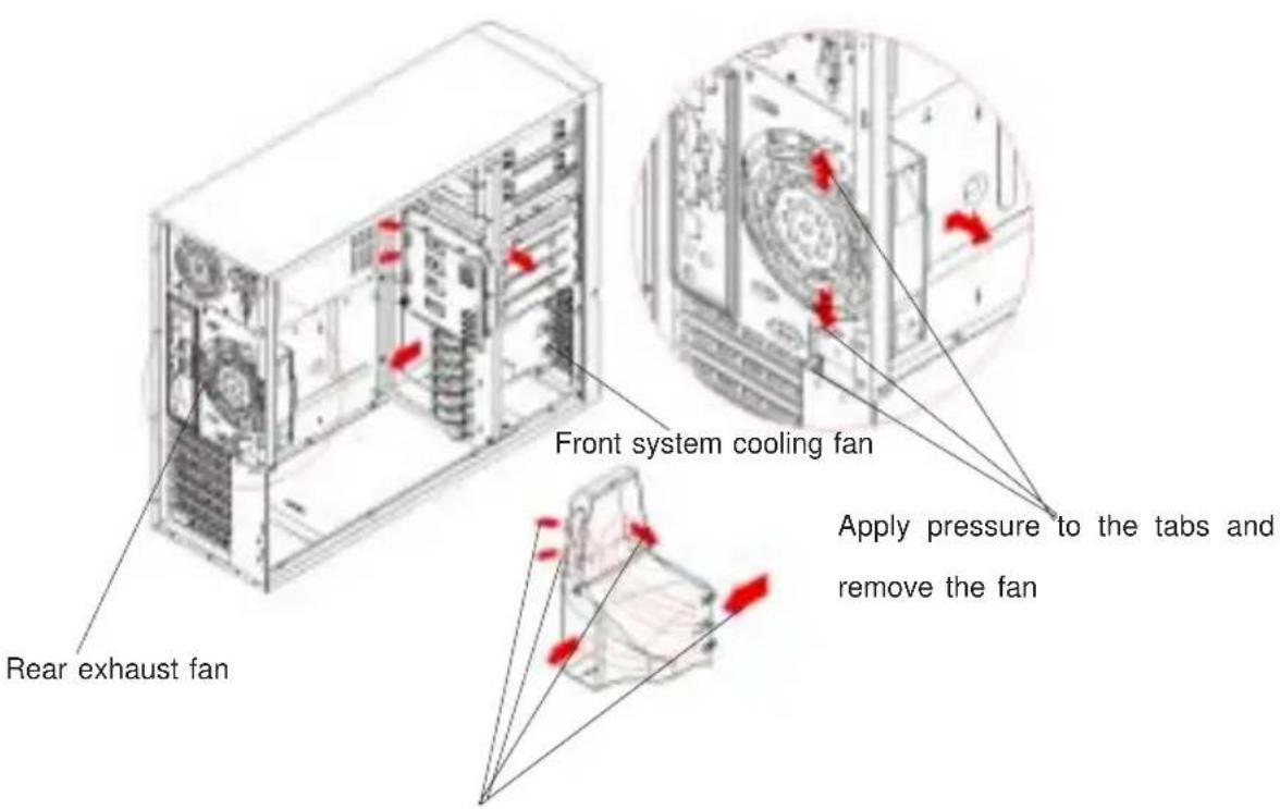
The airflow is directed to the hard drives, the add-on cards and the motherboard, resulting in optimal system cooling (SC733T).
Advantages of Supermicro's Cooling System
- The rear exhaust fan is a thermal-control fan. It has been optimized for low noise operation, which is ideal for office and workstation environments.
- Because of its uniquely designed shroud, the thermal-control front cooling fan can efficiently distribute air to the hard drives, the add-on cards and the overall system (SC733T).
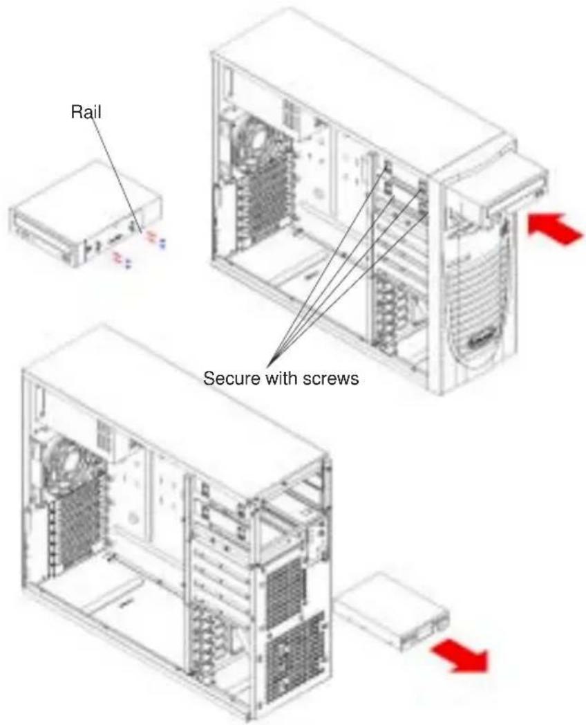
D. Removing Components from or Installing Devices into the 5.25" Drive Bays
After removing the side cover from the chassis, you can remove or install devices into the drive bays (refer to Section B for removing the side cover).
Procedure
- Remove the four screws from the 5.25" drive bay that you want to work with. (There are only 2 screws for the 3.5" floppy drive.)
- Slide the 5.25" dummy tray out from the front. (You can also install a 3.5" device in the dummy tray located at the bottom of the 5.25" drive bays.)
- Attach the drive mounting rail to the 5.25" device you wish to install and secure it with screws.
- Once the rail is attached to the device, slide the device into the 5.25" bay and secure the device with screws.
- Slide the side cover back to its position and secure it with screws.
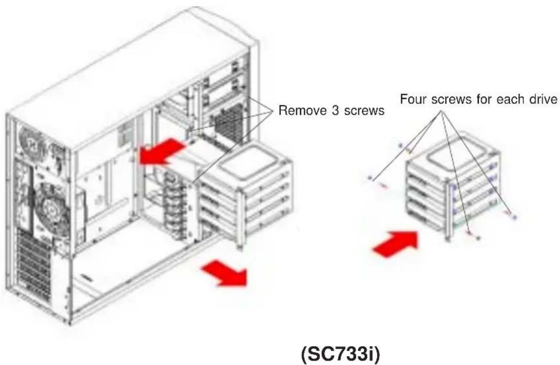
E. Removing Components from or Installing Devices into the 3.5" Drive Bays (SC733i only)
(For the SC733T chassis, you can access the hot swappable 3.5" drives from the front side of the chassis without removing the side cover. Please make sure to secure the drive tray with four screws after you have installed components into it.)
Please follow the procedures listed below to remove the 3.5" drives in order to install components into the drive bay (SC733i).
Procedure
-
First, remove the side cover from the chassis so you can remove components from or install devices into drive bays (refer to Section B).
-
Remove the three screws from the 3.5" drive brackets.
-
Pull the brackets toward the rear first and then pull them out from the chassis.
-
Install the 3.5" drive into a bracket and secure it with screws.
-
Once you've installed the 3.5" drives into the brackets, place the back assembly with the drives into the chassis.
-
Secure the bracket with the three screws you removed earlier.
-
Slide the side cover back to position and secure it with screws.
F. Removing the Front Chassis Cover and Accessing the Control Panel
(Unless you need to access the control panel's circuit board or the floppy drive, we do not recommend removing the front cover.)
Procedure
- Remove the side cover from the chassis (refer to Section B).
- Lift the two tabs inside the lip located at the bottom of the front cover.
- Using a flat screw driver, gently pry open the front cover.
- Once one side of the front cover is loose, pull the front cover completely out of the chassis as shown in Figure B.
- You can also remove the control panel's circuit board by removing the screw that fastens the control panel to the chassis.

(SC733i)
G. Configuring Jumper Settings for the Serial ATA Backplane
Important! Use extreme caution when working around the SATA backplane. Do not touch the backplane with any metal objects and make sure that no ribbon cables touch the backplane or obstruct the airflow holes in the SATA backplane. All SATA drive carriers must remain in the drive bays to promote proper airflow.
The Serial ATA (SATA) backplane supports four SATA drives. The SATA733 backplane is shown on the picture on the next page. The SATA drives' LED connector on the SATA backplane is JP26. There are also two power connectors on the backplane, and both connectors should be connected. Please do not cascade the SATA backplane. Please refer to the following table for the jumper settings:
| Jumper | Description Setting | |
| JP18 Buzzer Reset Alarm Reset Header | ||
| JP25 | Overheat Temperature Open: 45 Pins 1-2: 50irc C (Default) Pins 2-3: 55irc C | |
| JP26 SATA Drive Activity Drive Activity | ||
| JP28 Fan Sense Pins 1-2: Enable | Pins 2-3: Disable (Default) | |
(*Note: Please refer to the figures on the next page for the jumper locations.)
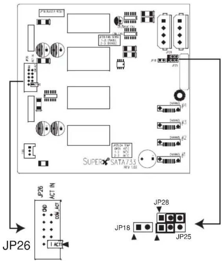
(*Note:▲=Pin 1)
SATA Backplane
- Table of Contents
- Unpacking and Check Lists
- The SC733 chassis contains the following:
- The accessory box contains the following:
- Removing the Side Cover of the SC733 Chassis
- Procedure to remove the side cover
- Removing the Rear Exhaust Fan and Installing the Motherboard
- Procedure
- Advantages of Supermicro's Cooling System
- Removing Components from or Installing Devices into the 5.25" Drive Bays
- Removing Components from or Installing Devices into the 3.5" Drive Bays (SC733i only)
- Removing the Front Chassis Cover and Accessing the Control Panel
- Configuring Jumper Settings for the Serial ATA Backplane
Brand : Supermicro
Model : SC733i-645
Category : Computer Case