
BCD925BDY - Refrigerator BAUMATIC - Free user manual and instructions
Find the device manual for free BCD925BDY BAUMATIC in PDF.

| Product Type | Twin Cavity Dual Fuel Cooker |
| Model | BCD925BDY (BCD920SS/BDY/BL/IV) |
| Overall Dimensions (W x D x H) | 900 mm x 600 mm x 760 mm (height adjustable to 885–940 mm) |
| Weight | Approximately 80 kg |
| Energy Supply | 220–240 V ~ 50 Hz, 20 A double pole switched fused outlet |
| Gas Connection | 1/2" BSP, natural gas 20 mbar (convertible to LPG) |
| Hob Type | 5-zone gas hob with automatic ignition |
| Hob Burners | 1 x 3.80 kW Triple Crown wok burner, 1 x 3.00 kW rapid, 2 x 1.80 kW semi-rapid, 1 x 1.00 kW auxiliary |
| Main Oven (Left) | Multifunction oven, 6 functions, net capacity 50 L |
| Secondary Oven (Right) | Static oven with grill, 3 functions, net capacity 35 L |
| Oven Functions | Defrost, Fan Oven, Conventional, Grill with Fan, Centre Grill, Light |
| Oven Lighting | Internal oven lights (E14 15 W/300°C bulb) |
| Control Panel | Rotary knobs for burners, oven functions, thermostat and LED programmer/timer |
| Timer Functions | Minute minder, duration, end cook, start & end time |
| Safety Features | Flame failure safety device on each burner, automatic ignition, stability chain, double-glazed cool-touch doors |
| Cleaning | Wipe-clean enamelled cavities, removable inner door glass, oven door removable for cleaning |
| Accessories Included | Trivet, 2 x enamelled baking trays, 3 x safety shelves, removable side racks, LPG conversion jets, wok stand |
| Optional Accessories | BPS2 Pizza Stone, BT2GRID Griddle Plate |
| Energy Efficiency Class | A/A |
| Installation Requirements | Freestanding, adjustable feet, must be secured with safety chain, ventilation as per BS 5440 |
| Warranty | Subject to Baumatic Conditions of Guarantee, excludes misuse |
Frequently Asked Questions - BCD925BDY BAUMATIC
User questions about BCD925BDY BAUMATIC
0 question about this device. Answer the ones you know or ask your own.
Ask a new question about this device
Download the instructions for your Refrigerator in PDF format for free! Find your manual BCD925BDY - BAUMATIC and take your electronic device back in hand. On this page are published all the documents necessary for the use of your device. BCD925BDY by BAUMATIC.
USER MANUAL BCD925BDY BAUMATIC
BCD1020SS 100 cm BCD920SS/ BDY/ BL/ IV 90 cm Twin cavity dual fuel cooker
INSTRUCTION MANUAL

natural_image
Simple line drawing of a fish with fins and tail, no text or symbols presentUser Manual for your Baumatic
BCD1020SS 100 cm BCD920SS/ BDY/ BL/ IV 90 cm
Twin cavity dual fuel cooker with gas hob

NOTE: This User Instruction Manual contains important information, including safety & installation points, which will enable you to get the most out of your appliance. Please keep it in a safe place so that it is easily available for future reference; for you or any person not familiar with the operation of the appliance.
GS 06/07/11
Contents
| Environmental note | 4 | ||||||||||||
| Important | safety | information | 5-9 | ||||||||||
| S | p | e | c | i | f | i | c | a | t | i | o | n | s |
| D | i | m | e | n | s | i | o | n | s | ||||
| S | p | e | c | i | f | i | c | a | t | i | o | n | s |
| E | l | e | c | t | r | i | c | a | l | d | e | t | |
| G | a | s | d | e | t | a | i | l | s | ||||
| Control | panel | 11 | - | 1 | |||||||||
| O | v | e | n | t | i | m | e | r | |||||
| Setting and using the oven programmer/ timer 13-16 | |||||||||||||
| Setting | the time of day | 13 | |||||||||||
| Setting the minute minder function 13-14 | |||||||||||||
| Setting | the duration function | 14 | |||||||||||
| Setting | the end cook function | 14 | |||||||||||
| Setting the start and end time function 15 | |||||||||||||
| Returning to manual operation mode 15 | |||||||||||||
| T | h | e | b | u | z | z | e | r | |||||
| Changing or cancelling a programmed function 15-16 | |||||||||||||
| U | s | i | n | g | t | h | e | h | o | b | |||
| H | o | b | s | u | r | f | a | c | e | l | a | ||
| Before | first use | 16 | - | 1 | |||||||||
| L | i | g | h | t | i | n | g | a | b | u | r | ||
| Optimum use of the burners 17-18 | |||||||||||||
| H | o | b | g | u | i | d | e | l | i | n | e | s | |
| U | s | i | n | g | t | h | e | o | v | e | n | ||
| Before | first use | 19 | - | 2 | |||||||||
| U | s | i | n | g | t | h | e | m | a | i | n | ||
| C | o | o | k | i | n | g | f | u | n | c | t | i | |
| Using | the secondary oven | 21 | |||||||||||
| Cooking guidelines | 23 | ||||||||||||
| W | a | r | n | i | n | g | s | ||||||
| C | o | o | k | i | n | g | t | i | p | s | |||
| Cleaning and maintenance 28-33 | |||||||||||||
| Cleaning | the gas hob top | 29 | |||||||||||
| A f | t e r e a c h u s e | ||||||||||||
| Cleaning | the burners 30 | ||||||||||||
| Cleaning | the oven 30 | ||||||||||||
| Replacing | the oven bulb 31 - | ||||||||||||
| Removing the oven door for cleaning 32-33 | |||||||||||||
| Removing the inner door glass for cleaning 32-33 | |||||||||||||
| I n s t a l l a t i o n 33 - 35 | |||||||||||||
| Positioning 35 - 36 | |||||||||||||
| Ventilation requirements 35 - 36 | |||||||||||||
| S e c u r i n g t h e b | |||||||||||||
| Fitting the safety chain and hook 30 | |||||||||||||
| E l e c t r i c a l c o n | |||||||||||||
| Connecting the main supply cable 38-39 | |||||||||||||
| G a s c o n n e c t i o n 39-40 | |||||||||||||
| Gas safety (installation and use) regulations 40 - 41 | |||||||||||||
| Gas connection 41 - | |||||||||||||
| Gas conversion to LPG 42-43 43 - | |||||||||||||
| Minimum flow adjustment for hob gas taps 42-43 43 - | |||||||||||||
| Gas tap replacement 44-46 47 | |||||||||||||
| My appliance isn't working correctly 44-46 47 | |||||||||||||
| Contact details 47 | |||||||||||||
This appliance is marked according to the European directive 2002/96/EC on Waste electrical and Electronic Equipment (WEEE). By ensuring this product is disposed of correctly, you will help prevent potential negative consequences for the environment and human health, which could otherwise be caused by inappropriate waste handling of this product.
The symbol

on the product, or on the documents accompanying the product, indicates that this appliance may not be treated as household waste. Instead it shall be handed over to the applicable collection point for the recycling of electrical and electronic equipment.
Disposal must be carried out in accordance with local environmental regulations for waste disposal.
For more detailed information about treatment, recovery and recycling of this product, please contact your local city office, your household waste disposal service or the shop where you purchased the product.
natural_image
Symbol of a trash bin crossed with a diagonal line and a horizontal line, representing waste sorting or disposal (no text present)- The packaging materials that Baumatic uses are environmentally friendly and can be recycled.
- Please discard all packaging material with due regard for the environment.
Important safety information

Your safety is of the utmost importance to Bauma. Please make sure that you read this instruction booklet before attempting to install or use the appliance. If you are unsure of any of the information contained in this booklet, please contact the Baumatic Advice Line.
General Information
- This appliance is designed for domestic household use and for the cooking of domestic foodstuffs.
- IMPORTANT: The adjacent furniture and all materials used in the installation must be able to withstand a minimum temperature of 85°C above the ambient temperature of the room it is located in, whilst in use.
o Certain types of vinyl or laminate kitchen furniture are particularly prone to heat damage or discolouration at temperatures below the guidelines given above. - Any damage caused by the appliance being installed in contravention of this temperature limit, or by placing adjacent cabinet materials closer than 25 mm to the appliance, will be the liability of the owner.
- IMPORTANT: Baumatic Ltd. DO NOT recommend that this appliance is installed on any type of marine vessel.
- The use of this appliance for any other purpose or in any other environment without the express agreement of Baumatic Ltd. will invalidate any warranty or liability claim.
- Your new appliance is guaranteed against electrical or mechanical defects, subject to certain exclusions that are noted in Baumatic's Conditions Of Guarantee. The foregoing does not affect your statutory rights.
- Repairs may only be carried out by Baumatic service engineers or their authorised service agents.
Warning and safety instructions
- This appliance complies with all current European safety legislation. Baumatic do wish to emphasise that this compliance does not remove the fact that the appliance surfaces will become hot during use and retain heat after operation.
Child Safety
○ Baumatic strongly recommend that babies and young children are prevented from being near to the appliance and not allowed to touch the appliance at any time. During and after use, all surfaces will become hot.
- If it is necessary for younger family members to be in the kitchen, please ensure that they are kept under close supervision at all times.
General Safety
√ Make sure that you understand the controls before using the appliance.
√ Check that all of the controls on the appliance are turned off after use.
√ Always stand back when opening the oven door, this will allow heat to disperse.
√ Take care when removing items from the oven, as the contents may be hot.
√ Always keep the oven doors closed when the oven is not in use.
√ Always follow the basic principles of food handling and hygiene; this will prevent the possibility of bacterial growth.
√ Always keep ventilation slots clear of obstructions.
√ Keep fingers away from the hinge areas when closing the door, otherwise you may trap them.
√ Oven gloves should be used when placing food in the oven cavity and when removing it. Care should be taken to avoid direct contact with any of the elements in the appliance.
- DO NOT LEAVE THE APPLIANCE UNATTENDED WHILST IN USE.
Do not place heavy objects on the oven door or lean on the oven door when it is open, as this can cause damage to the oven door hinges. Nobody should be allowed to sit or stand on any part of the cooker.
Do not store chemicals, food stuffs, pressurised containers in or on the cooker or in cabinets immediately above or next to the cooker.
- Do not heat up unopened food containers, as pressure can build up which may cause the container to burst.
Do not place flammable or plastic items on or near the hob burners, these types of materials should also not be placed in the oven or the compartment below the oven.
Do not leave heated oil or fat unattended, as this is a fire risk. You should not fill a deep fat frying pan more than one third full of fat or oil; you should also not use a lid.
- Do not allow fat or oil to build up in the oven trays, grill pan or oven base.
Do not place pans or baking trays directly on the base of the oven cavity, or line it with aluminium foil.
Do not grill food containing fat without using a grill trivet. The grill trivet should never be covered with aluminium foil.
- Do not place hot parts in water, leave them to cool first.
Do not allow vinegar, coffee, milk, saltwater, lemon, tomato juice or any liquid with high sugar content to remain in contact with the enamel parts of the appliance. Spillages should be wiped up immediately.
- Do not allow electrical fittings or cables to come into contact with areas on the appliance that get hot.
Do not use the appliance to heat the room it is located in or to dry clothing. No clothing should be placed over or near to the hob burners or oven door.
- Do not install the appliance next to curtains or soft furnishings.
Do not attempt to lift or move cooking appliances by using the oven door or handle, as this may cause damage to the appliance or result in injury to the person lifting the appliance.
Cleaning
- Cleaning of the oven should be carried out on a regular basis.
- Great care should be taken whilst using this appliance and when following the cleaning procedure.
- IMPORTANT: The appliance must be disconnected from the mains before following the cleaning procedure.
- IMPORTANT: Care must be taken when cleaning between the door glasses, and inside the inner frame as some of the edges maybe sharp due to the manufacturing process.
Installation

This appliance must be correctly installed by a suitably qualified person, strictly in accordance with the manufacturer's instructions. Please see the specific section of this booklet that refers to installation.
○ Baumatic Ltd. declines any responsibility for injury or damage, to person or property, as a result of improper use or installation of this appliance.
- Heat, steam and moisture will be created during use of the appliance, take care to avoid injury and ensure that the room is adequately ventilated. If the appliance is going to be used for prolonged periods of time, then additional ventilation may be required.
- Please consult with your qualified installer if you are in any doubt about the amount of ventilation that you will require.
Declaration of conformity
This appliance complies with the following European Directives:
2006/95/EC regarding "low voltage" 2004/108/EC regarding "electromagnetic disturbances" -89/109/EEC regarding "materials in contact with food".
- The above directives comply with 93/68/EEC regarding CE marking.
The manufacturer declares that the oven is built using certified materials and requires the appliance to be installed in accordance with the standards currently in force. This appliance must be used by a trained person for domestic purposes only.
Specifications
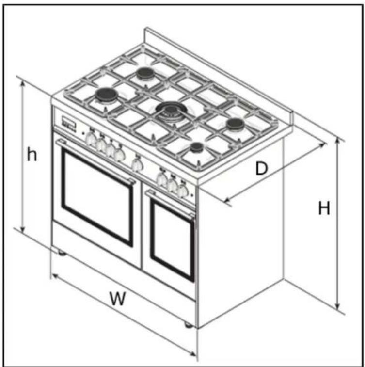
BCD1020SS
h= 900 mm
H = 910 - 920 mm
W = 1000 mm
D = 600 mm
BCD920SS/ BDY/ BL/ IV
h= 760 mm
H = 885 - 940 mm
W = 900 mm
D = 600 mm
Product specifications:
- 5 zone gas hob:
- 1 x 3.80 kW triple crown wok burner
- 1 x 3.00 kW rapid burner
- 2 x 1.80 kW semi-rapid burners
- 1 x 1.00 kW auxiliary burner
- Flame failure safety device on each burner
○ Automatic ignition
o Heavy duty cast iron pan stands
o Energy efficiency class: A/ A
o LED full programmer
○ Cooling fan - Oven lights
o Thermostatically controlled grill (main oven)
o Fixed grill (secondary oven) - Double-glazed removable "cool touch" doors
- Removable full inner glasses
- Wipe Clean enamelled cavities
○ Adjustable feet
Left oven: Multifunction oven
- 6 functions
- Net oven capacity: 50 litres
○ Gross oven capacity: 64 litres
Right oven: Static oven with grill
- 3 functions
- Net oven capacity: 35 litres
○ Gross oven capacity: 43.5 litres
Standard accessories:
○ Trivet
o WipeClean enamelled baking tray with handle
- WipeClean enamelled baking tray
- 3 x Safety shelves
- Removable side racks
o LPG conversion jets
○ Wok stand
Optional extras:
○ BPS2 Pizza Stone
- BT2GRID Griddle Plate With Handles
Electrical details
Rated Voltage: 220 - 240 Vac 50 Hz
Supply Connection: 20 A (double pole switched fused outlet with 3mm contact gap)
Max Rated Inputs: 3.25 kW
Mains Supply Lead: 3 core x 1.5 mm ^4 (not supplied)
Oven Light Bulb: E14 15 W/300°C screw type pygmy
Gas details
Gas Connection Type: 1/2" BSP
Gas Type (Natural Gas): 20 mbar
For future reference please record the following information which can be found on the rating plate and the date of purchase which can be found on your sales invoice. The rating plate for your oven can be located by opening the door of the storage compartment.
Model Number
Serial Number
Date of Purchase ....
Control Panel
Cooking zone selection dial
- Turn the relevant dial anticlockwise to select a power level for a chosen burner.
0 = Burner OFF position

- Low temperature

– High temperature
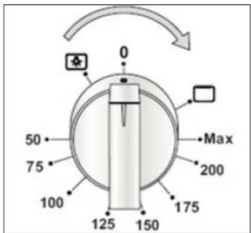
Thermostat control knob (main oven)
- Use this control knob to control the temperature in the oven.
Oven function control knob

- Use this control knob to select a function for the main oven.
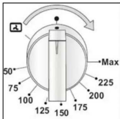
Thermostat control knob (secondary oven)
- Turn this control dial to the grill symbol to turn on the fixed grill function. - Turn the control knob to the light icon to switch the oven light on and begin the conventional oven function. You can then proceed to set the oven temperature.
Oven timer
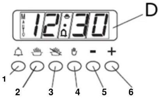
1) Minute minder button
2) Cooking time selection button
3) End of cooking time selection button
4) Manual operation mode button
5) Timer minus button
6) Timer plus button
D = Digital display
Setting and using the oven programmer/ timer
Setting the time of day
After switching on your oven for the first time you should also set the time of day.
- After connecting the appliance to the electricity supply, or after a power cut, "AUTO" and "0.00" will flash simultaneously on the digital display.
- Press the cooking time selection button (2) and the end of cooking time selection button (3) simultaneously.
- Set the current time using the timer minus (5) and timer plus (6) buttons. Once the desired time has been chosen, the "AUTO" symbol will turn off and the cooking time selection icon (2) will turn on. This indicates the oven is in manual operation mode.
Setting the minute minder function (main and secondary oven)
You are able to set the minute minder at any time, regardless of whether an oven function has been selected. You can set a period of time using the minute minder function and an alarm will sound when this period of time has elapsed.
o Press the minute minder button (1) to set a countdown time.
- Use the timer minus (5) and timer plus (6) buttons to set the required length of time. You can programme any time between 0.01 min - 0.59 min.
- The minute minder symbol (1) will turn on and the countdown will begin automatically after a time is set.
- At the end of the set time, a buzzer will sound and the minute minder icon will go off.
- Important: The oven will continue to heat once the alarm has been silenced. If you have finished cooking, then you should turn the thermostat control knob to 0.
Setting the duration cooking function
This function will allow you to set a countdown time similar to the minute minder function. However the oven will no longer continue to heat, once the countdown period has elapsed.
- Press the cooking time selection button (2) and use the timer minus (5) and timer plus (6) buttons to set the length of cooking time you require. You can set a time between 0.01 min – 23.59 min.
- The “AUTO” and cooking symbols will turn on and remain lit for the time the function is operating.
- At the end of the set time, the cooking time selection icon (2) will turn off and the “AUTO” symbol will flash. A buzzer will sound to indicate the end of the cooking time.
Setting the end cook function
This function is similar to the duration function, however instead of selecting a period of time that you wish the oven to switch off after. You select the time of day that you wish the oven to switch off at.
- Press the end of cooking time selection button (3) and use the timer minus (5) and timer plus (6) buttons to set the time of day you wish the function to switch off. You can set a time of day between 0:01 – 23:59 hrs.
- The “AUTO” and cooking symbols will turn on and stay on while the function is in progress.
- When the programmed time of day is reached, the cooking time selection icon (2) will turn off and the "AUTO" symbol will flash. A buzzer will also sound to indicate the end of cooking time.
Setting the start and end time function
This function will allow you to set a time in the future that the oven switches on at and a time that the oven will switch off at.
- First programme a cooking time using the steps outlined in the 'Setting the duration cooking function' section above. Both the "AUTO" and cooking time selection symbol (2) will turn on.
- Then programme an end of cooking time using the steps outlined in the ‘Setting the end cook function’ section above. The cooking time selection symbol (2) will turn off.
- The cooking time selection symbol (2) will turn on again at the desired oven start time. At the end of the cooking time, the symbol will turn off and the “AUTO” icon will flash. A buzzer will also sound to indicate the set time has been reached.
Returning to manual operation mode
- You can only return to the manual operation mode when any automatic timer function has finished or been cancelled.
To return to manual operation mode, press the manual operation mode button (4). The "AUTO" icon will disappear and the cooking symbol (2) will turn on.
The buzzer
- The buzzer will go off at the end of a programme or at the end of the minute minder function. The alarm will last approximately seven minutes before automatically turning off.
- The buzzer can be stopped by pressing any of the function buttons.
Changing or cancelling a programmed function
- An automatic function programming error will occur if the time shown on the clock is between the cooking start time and the cooking end time. This error will be signalled immediately by a buzzer and the “AUTO” symbol will flash.
○ A setting error can be corrected by altering the duration or end of cooking time.
- Any programme that has been set can be corrected at any time by pressing the corresponding programming button and the timer plus (6) and timer minus (5) buttons.
To cancel a programme, change the time set to "0.00". If a programmed time is cancelled, the end of cooking function is cancelled too and visa versa.
- The oven will turn off automatically and the “AUTO” symbol will flash. Press the manual operation mode button (4) to return to manual operation mode.
The time of day cannot be corrected when an automatic timer function is in progress.
Using the hob top
Hob surface layout

1) 3.80 kW triple crown (wok) burner
2) 3.00 kW rapid burner
3) 1.80 kW semi-rapid burner
4) 1.00 kW auxiliary burner
Before first use

IMPORTANT: You should clean the hob surface (see "Cleaning and maintenance" section).
- You should switch on one cooking zone at a time, for 5 minutes at the maximum setting. This will help to eliminate any new smell that exists and evaporate any humidity that has formed on the heating elements during transit.
- Do not burn off more than one zone at once.
- You must place a saucepan filled half full with cold water on each zone as you burn it off.
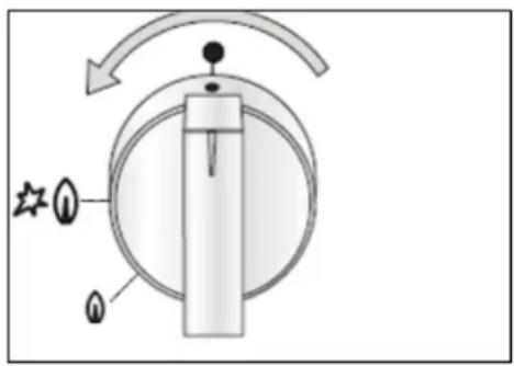
Lighting a burner

o Press the relevant burner dial and rotate anticlockwise to the large flame icon. Release the dial and the burner will automatically ignite.
o Matches can also be used to light the burner during a power cut. Simply follow the previous step but place a lit match to the burner as you press the dial. Once lit, keep the dial pressed for about ten seconds.
WARNING: Extra care should be taken when lighting a burner with matches. There is a risk of burning as the cooking zone ignites so take necessary precautions.
Optimum use of the burners
- In order to achieve maximum results with the minimum consumption of gas, it is important to adjust the flame according to your needs and to use the appropriate size pans (see table below).
When the contents of a pan begin to boil it is recommended that you adjust the dial to the small flame position.
○ Always place a lid on the pan in use.
| Burner Diameter of pan (cm) | |
| Triple crown | 22 – 24 |
| Rapid 20 | - 22 |
| Semi-rapid | 16 – 18 |
| Auxiliary 1 | 2 - 14 |
○ Always remember to turn the control knob to OFF when cooking is completed.

- The appliance is equipped with pan supports (1), on which the wok support (2) must be placed. To ensure stability, position the notch (A) of the wok support on the pan support fingers as indicated in the diagram above.
Hob guidelines
- The first few times the hob top is used, it may give off an acrid, burning smell. This smell will disappear completely with repeated use.
- The worktop is fitted with cooking areas of different diameter and power.
- The positions where the heat will radiate from are clearly marked on the hob top. The saucepans must be positioned exactly on these zones for efficient heating to occur. Pans should have the same diameter as the cooking zone that they are being used on.

natural_image
Diagram showing two cooking pots with crossed-out handles, one with a spring and the other with a gas stove (no text or symbols)- You should not use saucepans with rough bottoms, as this can scratch the surface.
Before use, make sure that the bottoms of the saucepans are clean and dry.
- When cold, the bottom of the pans should be slightly concave, as they expand when hot and lie flat on the surface of the hob. This will allow the heat to transfer more easily.
- The best thickness for the bottom of the pans is 2 – 3 mm of enamelled steel and 4 – 6 mm for stainless steel with sandwich type bottoms.
- If these rules are not followed, then there will be a great loss of heat and energy. Heat not absorbed by the saucepan, will spread to the hob, frame and surrounding cabinets.
o Preferably cover pans with a lid to permit cooking at a lower heat. - Always cook vegetables and potatoes, etc. in as little water as possible to reduce cooking times.
- Food or liquid that has a high sugar content may damage the hob top if it comes into contact with the hob surface. Any spillages should be wiped up immediately, however this may not prevent the hob surface from becoming damaged.
- IMPORTANT: The hob surface is tough; however it is not unbreakable and can be damaged. Especially if pointed or hard objects are allowed to fall on it with some force.
- DO NOT USE THE HOB IF THE SURFACE BECOMES BROKEN OR CRACKED. YOU SHOULD CONTACT THE BAUMATIC SERVICE DEPARTMENT IMMEDIATELY.
Using the oven
Before first use
To remove any residue from the oven that may have been left from the manufacturing process, you should select either the main or grill oven function and turn the thermostat dial to its maximum temperature setting.
- It is perfectly normal for a smell to be produced during this process.
- You should make sure that any windows in the room are left open during this process.
- It is advisable for you not to remain in the room whilst the burning off process is taking place.
- You should leave each oven on maximum setting for 30 - 40 minutes.
○ IMPORTANT: You should not burn off both ovens simultaneously.
○ After both cavities have cooled, they should then be cleaned with warm soapy water, using either a sponge or soft cloth. No abrasive cleaners should be used.
- Outer parts of the oven should be cleaned with warm soapy water, using either a sponge or soft cloth. No abrasive cleaners should be used.
- We would recommend that an appropriate stainless steel cleaner and polish is regularly used on the stainless steel surfaces of this appliance.
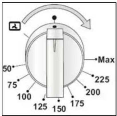
Using the main oven

You can rotate this dial in either direction to select an oven function for the main oven.
The oven temperature control knob should be turned clockwise to select the oven temperature.
There are six cooking functions available on your appliance:

DEFROST MODE: The fan runs without heat to reduce the defrosting time of frozen foods. The time required to defrost the food will depend on the room temperature, the quantity and type of food. Always check food packaging for the defrosting instructions.

FAN OVEN: This method of cooking uses the top and bottom heating elements with the fan. This results in the heat being evenly distributed in the cavity to cook food simultaneously on different shelves and also prevents the transmission of smells and tastes from one dish to another.

CONVENTIONAL OVEN: This method of cooking provides traditional cooking, with heat from the top and lower elements. This function is suitable for roasting and baking on one shelf only.

GRILL WITH FAN: This cooking method uses the top element in conjunction with the fan, to help give a fast circulation of heat. Suitable where quick browning is required and “sealing” the juices in, such as with steaks, hamburgers, some vegetables etc.

CENTRE GRILL: This cooking method is normal grilling, utilising the inner part only of the top element, which directs heat downwards onto the food. Suitable for grilling small portions of bacon, toast, meat etc.
LIGHT CONTROL: Turn the control knob to this icon to turn the oven light on and off.
Using the secondary oven

- The control knob should be turned clockwise to select the fixed grill function.
- You can also turn the dial to the light icon which will turn on the oven light and switch on the conventional oven function too. You can then proceed to set the oven temperature.
IMPORTANT: The grill door must be closed when using the grill function.

CONVENTIONAL OVEN: This method of cooking provides traditional cooking, with heat from the top and lower elements. This function is suitable for roasting and baking on only.

FULL GRILL: This method of cooking utilises the inner and outer parts of the top element, which directs heat ds onto the food. This function is suitable for grilling medium portions of sausages, bacon, steaks, fish etc.

natural_image
Line drawing of a rectangular grating or fan with horizontal slats and two side handles (no text or symbols)REMEMBER: When using any of the grill important to place a drip pan at the base of the oven cavity to collect any juices which may drip down (see image below).

natural_image
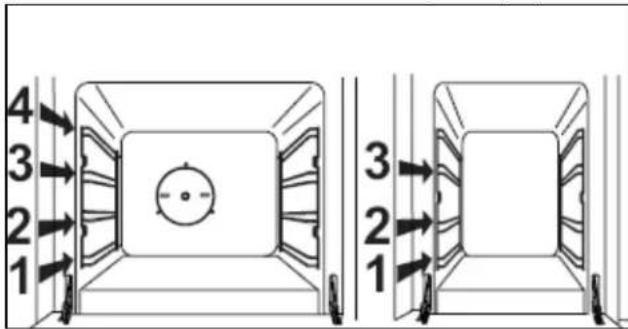
Technical line drawing of two mechanical components with internal gear-like structures, no text or symbols presentThe oven walls of the two cavities are fitted with various guide bars on which you can place an oven shelf or a drip tray (see image below).
Cooking guidelines
- Please refer to the information given on food packaging for guidance on cooking temperatures and times. Once familiar with the performance of your appliance, temperatures and times can be varied to suit personal preference.
○ Make sure that frozen foods are thoroughly thawed before cooking, unless the instructions on the food packaging advise that you can “cook from frozen”. - You should pre-heat the oven and not place food inside of it is properly heated.
- Before cooking, check that any unused accessories are removed from the oven.
- Place cooking trays in the centre of the oven and leave gaps between the trays to allow air to circulate.
- Try to open the door as little as possible to view the dishes.
Warnings
- Keep the oven door closed when using either the grill or oven functions.
During cooking, never place pans or cookware directly onto the bottom of the oven. They should always be placed on the shelves provided. - The grill heating element becomes extremely hot during operation, avoid touching it inadvertently when handling the food which you are grilling.
- Important: Be careful when opening the door, to avoid contact with hot parts and steam.
- IMPORTANT: In case of fire, close the main valve of the gas supply and switch off the electricity supply to the appliance. NEVER pour water onto burning oil.
For general cooking guides for each of the ovens, please see the tables on the following page.
Cooking tips
Cooking guide for the main oven
Multifunction oven:
| FOODS | WEIGHT(kg) | Position of the oven shelf from the bottom | Conventional Oven Temperature (°C) | Conventional Oven Cooking / Baking Time (mins) | Conventional Oven + Fan Temperature (°C) | Conventional Oven + Fan Cooking / Baking Time (mins) |
| Meat Loafs | ||||||
| Roasted veal | 1 1 - | 2 200 - 22 | 5 100 - 120 19 | 0 100 - 120 | ||
| Roast beef | 1 1 - 2 20 | 0 - 225 40 | - 50 190 40 | - 50 | ||
| Roasted pork | 1 1 - | 2 200 - 22 | 5 100 - 120 19 | 0 100 - 120 | ||
| Roasted lamb | 1 1 - | 2 200 - 22 | 5 100 - 120 19 | 0 100 - 120 | ||
| Game | ||||||
| Roast hare | 1 1 - 2 22 | 5 - MAX 5 | 0 - 60 225 - MAX 50 | |||
| Roast pheasant | 1 1 - | 2 225 - MAX | 60 - 70 225 - MAX 60 | |||
| Roast partridge | 1 1 - | 2 225 - MAX | 50 - 60 | 225 - MAX 50 | ||
| Poultry | ||||||
| Roasted chicken | 1 - 2 | 1 - 2 2 | 00 - 225 80 - 9 | 0 190 70 - 80 | ||
| Roasted turkey | 1 - 2 | 1 - 2 2 | 00 - 225 100 - | 120 190 | 90 - 110 | |
| Roasted duckling | 2 - 3 | 1 - 2 | 200 - 225 | 90 - 110 | 190 | 80 - 100 |
| Fish | ||||||
| Roasted whole fish | 1 2 | 20 | 0 30 - 35 170 | - 190 25 - 30 | ||
| Sea bass | 1 | 2 | 175 | 20 - 25 | 160 - 170 | 15 - 20 |
| Baked pasta | ||||||
| Lasagne 2.5 | 2.5 | 2 21 | 0 - 225 60 - 75 | 225 - MAX 30 | - 40 | |
| Cannelloni | 2.5 | 2 | 210 - 225 | 60 - 75 | 225 - MAX | 30 - 40 |
| Pizza | 1 | 2 | 225 - MAX | 25 - 30 | 225 - MAX | 20 - 25 |
| Bread | 1 | 2 | 225 - MAX | 20 - 25 | 220 | 20 |
| Patisserie | ||||||
| Biscuits (general) | N/A | 2 | 190 | 15 | 170 - 190 | 15 |
| Shortcrust pastry | N/A | 2 | 200 | 20 | 190 - 200 | 20 |
| Cakes / Flans | ||||||
| Angel cake / sponge | 0.8 | 2 | 190 | 52 | 170 - 190 | 45 |
| Fruit cake | 0.8 | 2 | 200 | 65 | 190 - 200 | 65 |
| Chocolate cake | 0.8 | 2 | 200 | 45 | 190 - 200 | 45 |
| Victoria sponge | 0.8 | 2 | 200 | 40 - 45 | 190 - 200 | 40 - 45 |
The information in this table is approximate and may vary according to individual needs.
Grilling in main oven:
| Conventional Oven Conventional Oven + Fan | ||||||||
| FOODS | WEIGHT (kg) | Position of the oven shelf from the bottom | Temperature (°C) | Grilling time 1^st side (mins) | Grilling time 2^nd side (mins) | Temperature (°C) | Grilling time 1^st side (mins) | Grilling time 2^nd side (mins) |
| Meat | ||||||||
| T-Bone steak | 0.50 | 3 | 225 - | MAX | 15 15 | 200 | ||
| Steak | 0.15 | 3 | 225 | - | MAX | 5 | 5 | |
| Chicken (cut in half) | 1 | 2 - 3 | 225 - MAX | 25 | 25 | 200 | 18 | 18 |
| Fish | ||||||||
| Trout | 0.42 | 3 | 225 - MAX | 18 | 18 | 200 | 10 | 10 |
| Sea bass | 0.40 | 3 | 225 - MAX | 15 | 15 | 200 | 10 - 12 | 10 - 12 |
| Sole | 0.20 | 3 | 225 - MAX | 10 | 10 | 200 | 8 - 9 | 8 - 9 |
| Bread | ||||||||
| Toast | N/A | 3 - 4 | 225 - MAX | 2 - 3 | 2 - 3 | 200 | 2 - 3 | 2 - 3 |
The information in this table is approximate and may vary according to individual needs.
Cooking guide for the secondary oven
Conventional oven:
| FOODS | WEIGHT (KG) | Position of the oven shelf from the bottom | Temperature (°C) | Cooking / Baking Time (mins) |
| Meat Loaf | ||||
| Roasted veal | 1 | 1 | 220 | 80 |
| Roast beef | 1 | 1 | 200 – 225 | 40 – 50 |
| Roasted pork | 1 | 1 | 200 | 80 |
| Roasted lamb | 1 | 1 | 200 - 225 | 100 – 120 |
| Game | ||||
| Roast hare | 1 | 1 – 2 | 225 – MAX | 50 – 60 |
| Roast pheasant | 1 | 1 – 2 | 225 – MAX | 60 – 70 |
| Roast partridge | 1 | 1 - 2 | 225 - MAX | 50 - 60 |
| Poultry | ||||
| Roasted chicken | 1 | 1 – 2 | 200 – 225 | 80 – 90 |
| Roasted turkey | 1 | 1 – 2 | 200 – 225 | 100 – 120 |
| Roasted | 1 | 1 - 2 | 200 - 225 | 90 - 110 |
| duckling | ||||
| Fish | ||||
| Roasted whole fish | 1 1 - | 2 200 30 - 35 | ||
| Sea bass 1 | 1 - 2 175 | 20 - 25 | ||
| Baked pasta | ||||
| Lasagne 2.5 | 1 - 2 210 | - 225 60 - 75 | ||
| Cannelloni 2 | 5 1 - 2 210 | - 225 60 - 75 | ||
| Pizza 1 2 | MAX 20 - 22 | |||
| Bread 1 2 | MAX 20 - 25 | |||
| Patisserie | ||||
| Biscuits (general) | N/A | 2 | 190 | 20 |
| Shortcrust pastry | N/A | 2 | 200 | 20 |
| Cakes / Flans | ||||
| Angel cake / sponge | 0.8 | 1 | 190 | 50 |
| Fruit cake | 0.8 1 - | 2 200 65 | ||
| Chocolate cake | 0.8 1 - | 2 200 45 | ||
| Victoria sponge | 0.8 | 2 | 200 | 40 - 45 |
The information in this table is approximate and may vary according to individual needs.
Grilling in secondary oven
| Cooking / Baking time (mins) | ||||
| FOODS | WEIGHT (kg) | Position of the oven shelf from the bottom | 1^st side | 2^nd side |
| Meat | ||||
| T-Bone steak | 0.50 | 3 | 12 | 12 |
| Steak | 0.15 | 3 | 5 | 5 |
| Chicken (cut in half) | 1 | 2 - 3 | 25 | 25 |
| Fish | ||||
| Trout | 0.42 | 3 | 10 | 10 |
| Sole | 0.20 | 3 | 10 | 10 |
| Bread | ||||
| Toast | N/A | 3 | 3 | 3 |
The information in this table is approximate and may vary according to individual needs.
Cooking tips for cakes and bread
- Heat the oven for at least 15 minutes before you start cooking bread or cakes.
- Do not open the door during baking because the cold air will stop the yeast from rising.
- When the cake is cooked turn the oven off and leave it in for about 10 minutes.
- Do not use the enamelled baking tray or drip pan to cook cakes in.
To test if a cake is cooked, about 5 minutes before the end of cooking time, put a cake tester or skewer in the highest part of the cake. If it comes out clean, the cake is cooked.
○ If the cake sinks, next time use less liquid or lower the temperature by 10^ C. - If the cake is too dry, make some tiny holes with a toothpick and pour some drops of fruit juice or spirits on it. The next time, increase the temperature by 10°C and set a shorter cooking time.
- If the cake is too dark on top next time put the cake on a lower shelf and cook it at a lower temperature for longer.
- If the top of the cake is burnt, cut off the burnt layer and cover with sugar or decorate with cream, jam and confectioner's cream.
- If the cake is too dark underneath next time place it on a higher shelf and cook it at a lower temperature.
- If the cake or bread is cooked nicely outside but is still uncooked inside, next time use less liquid and cook at a lower temperature for longer.
- If the cake will not come out of the tin, slide a knife around the edges, place a damp cloth over the cake and turn the tin upside down. Next time, grease the tin well and sprinkle with flour or bread crumbs.
- If the biscuits will not come away from the baking tray, put the tray back in the oven for a while and lift the biscuits up before they cool. The next time use a sheet of baking parchment to prevent this happening again.
Cooking tips for meat
○ If, when cooking meat, the time needed is more than 40 minutes, turn the oven off 10 minutes before the end of cooking time to exploit the residual heat and save energy.
- Your roast will be juicer if cooked in a closed pan. It will be crispier if cooked without a lid.
○ Normally white meat, poultry and fish need medium temperatures (less than 200^ C).
To cook "rare" red meats, high temperatures (over 200°C) and short cooking times are needed.
- For a tasty roast, lard and spice the meat.
- If your roast is tough, next time leave the meat to ripen longer.
- If your roast is too dark on top or underneath, next time put it on a higher or lower shelf, lower the temperature and cook for longer.
- If your roast is undercooked, cut it in slices and arrange the slices on a baking tray with gravy and finish cooking it.
Cleaning and maintenance

Cleaning operations must only be carried out when the oven is cool.
The appliance should be disconnected from your mains supply before commencing any cleaning process.
- The oven should be thoroughly cleaned before it is operated for the first time and after each use. This will avoid residual food stuffs becoming baked on the oven cavity. After residues have been baked on several times, they are far more difficult to remove.
- Never clean the oven surfaces by steam cleaning.
- The oven cavity should only be cleaned with warm soapy water, using either a sponge or soft cloth. No abrasive cleaners should be used.
- Any stains that may appear on the bottom of the oven will have originated from food splashes or spilt food, these splashes occur during the cooking process. These could possibly be a result of the food being cooked at an excessively high temperature or being placed in cookware that is too small.
- You should select a cooking temperature that is appropriate for the food that you are cooking. You should also ensure that the food is placed in an adequately sized dish and that you use the enamelled baking tray where appropriate.
- Outer parts of the oven should only be cleaned with warm soapy water, using either a sponge or soft cloth. No abrasive cleaners should be used.
- We would recommend that an appropriate stainless steel cleaner and polish is regularly used on the stainless steel surfaces of this appliance.
- If you use any form of oven cleaner on your appliance, then you must check with the manufacturer of the cleaner that it is suitable for use on your appliance.
- Any damage that is caused to the appliance by a cleaning product will not be fixed by Baumatic free of charge, even if the appliance is within the guarantee period.
Cleaning the gas hob top
- Remove the dirty pan supports from the hob and place in warm soapy water for some time. Then wash and dry before replacing.
After each use
○ Wipe the appliance over with a damp cloth and a little washing up liquid.
o Dry the appliance by rubbing the surface with a clean cloth.
Cleaning the burners
- Gas burners should be cleaned regularly and after each spillage to remove cooking residues and dirt.

To clean the burners, remove the caps and rings and place them separately in warm soapy water. After cleaning them, check that the burner ports are clear.
The body near the nozzle should always be clean. Dirt accumulating around the nozzle may clog it, as a result of which the burner will not light or will light only with a small flame. To clean the nozzle use a brush soaked in solvent.
Dry all the elements of the burner carefully as wet elements may not light properly. Assemble the clean and dry burners carrying out the disassembly steps in reverse order.
Cleaning the oven
The oven compartment is coated with vitreous enamel. To clean particularly difficult burnt spots a special oven cleaning agent may be used. However, as these agents are caustic, be careful when using them and follow the manufacturer's guidelines.
Warning: Do not steam pressure clean the oven. Always wait until the oven cools down before cleaning.
Replacing the oven bulb

IMPORTANT: The oven must be disconnected from your mains supply before you attempt to either remove or replace the oven bulb.
o Draw out the side guide rails in order to provide access to the bulb.
Flat lamps
- Remove the glass protection cap (C) from the bulb socket by lifting it with a screwdriver placed between the cap and the oven wall.
○ Replace the bulb (B) with a 15 W/300°C, screw type pygmy.
- Do not use any other type of bulb.
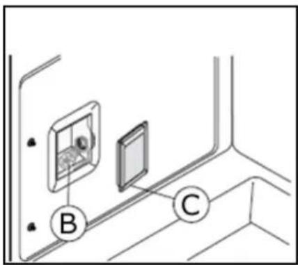
- Screw the lamp cover back into its original position.
Round lamps

○ Turn the glass protection cap (A) anti-clockwise and change the lamp (B).
o Refit the cap by screwing it back in a clockwise direction.
Removing the oven door for cleaning
- The oven door can be removed to give easier access to the oven when cleaning.
- Open the oven door and insert a rivet or nail (R) in the hole (F) of the hinge (see image below).

o Partially close the door, forcing it upwards at the same time to free the stop tooth and hinge sector.
Once the hinge is free, pull the door forwards tilting it slightly upwards to free the sector.
To reassemble, proceed in the reverse order, playing attention to the correct position of the sectors.
Removing the inner door glass for cleaning
Ensure the top cavity is cold before cleaning.
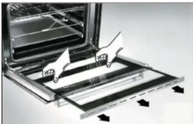
natural_image
Illustration of a kitchen oven with two hands operating the tray, showing airflow direction (no text or symbols)o Simply open the oven door and remove the support securing the glass. The glass will then slide out easily.
- To replace the glass, follow the first step in reverse.
WARNING: This procedure can be carried out with the door fitted on the appliance but pay attention that when the glass is pulled upwards, the force of the hinges can close the door roughly.
- IMPORTANT: You should make sure that the door is supported at all times and that you place the door on some padded material whilst cleaning it.
- The oven door and door glass should only be cleaned using a damp cloth and a small amount of detergent. The cloth MUST NOT have come into contact with any form of cleaning product or chemical previously.
Installation

The installation must be carried out by a suitably qualified person, in accordance with the current version of the following.
- UK Regulations and Safety Standards or their European Norm Replacements.
○ Building Regulations (issued by the Department of the Environment).
○ Building Standards (issued by the Scottish Development Department).
○ IEE Wiring Regulations. - Electricity At Work Regulations.
○ Gas Safety (Installation and Use) (Amendment) Regulations.
Positioning

The adjacent furniture and all materials used in the installation must be able to withstand a minimum temperature of 85^ C above the ambient temperature of the room it is located in, whilst in use.
- Your appliance is heavy, so you should be careful when moving or positioning it.
- Do not try to move the cooker by pulling on either the door, handle or control panel.
- It can also be used as freestanding, with a cabinet to one side, in a corner setting or with its back to a wall.
○ IMPORTANT: It should not be installed at the end of a run of cabinets, if there is a cabinet at immediate right angles to the cooker door.
- The wall behind the cooker and 450 mm above and across the width of the cooker should be an incombustible material and preferably an easy clean surface, such as ceramic tiles.
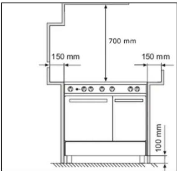
○ Any overhanging surface or cooker hood should be at least 700 mm above the highest point on the hob top (including the burners).
○ Baumatic do not recommend that the cooker is positioned below wall cupboards, as the heat and steam from the appliance and what is being cooked, may damage the cupboard and its contents.
- The cooker may be located in a kitchen, or a bedroom, but not in a room containing a bath or shower. The cooker must not be installed in a bedroom of less than 20m^3 in size.
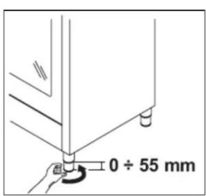
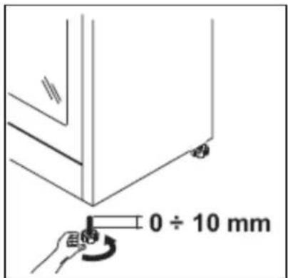
- The cooker is fitted with four legs that can be adjusted to match the height of your kitchen cabinets.
- If the cooker is not level or is unstable due to an uneven floor surface, use the adjustable feet to alter each corner until the cooker is level.
To assemble them it is necessary to raise the cooker and to screw the four legs into position, on each corner of the base of the appliance.
○ IMPORTANT: They must be screwed clockwise into position and not just slotted into the holes on each corner. You must screw them through the brackets that are also provided.
Ventilation requirements
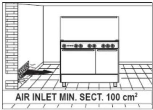


- The room containing the cooker should have an air supply in accordance with the current edition of BS 5440: Part 2:
- The room must have opening windows or equivalent; some rooms may also require a permanent vent.
○ If the room has a volume between 5 and 10m ^3 , it will require an air vent of 50cm ^2 (effective area). Unless it has a door which opens directly to the outside.
○ If the room has a volume of less than 5m^3 , it will require an air vent of 100cm^2 (effective area).
- If there are any other fuel burning appliances in the same room the current edition of BS 5440: Part 2: should be consulted to determine air vent requirements.
- Ensure that the room containing the cooker is well ventilated, keep natural ventilation holes or install a mechanical ventilation device (mechanical cooker hood).
- Prolonged intensive use of the appliance may call for additional ventilation, either by the opening of a window, or by increasing the level of the mechanical ventilation device (where present).
- This cooker is not fitted with a device for discharging the products of combustion. Ensure that the ventilation rules and regulations are followed.
○ Excess steam from the oven, vents out at the top back edge of the cooker, so make sure that the walls behind and nea cooker are resistant to heat, steam and condensation.
- Your cooker must stand on a flat surface so that when it is in position the hob is level. When in position check that the cooker is level by using a spirit level and adjust the 2 feet at the rear and the 2 feet at the front if necessary.
- Remember that the quantity of air necessary for combustion must never be less than 2m^3/h for each kW of power (see total power in kW on the appliance rating plate).
Securing the back-guard
- In order to attach the back-guard (A) to the appliance, you need to loosen the screws (B) positioned on the back of the hob (see image below).
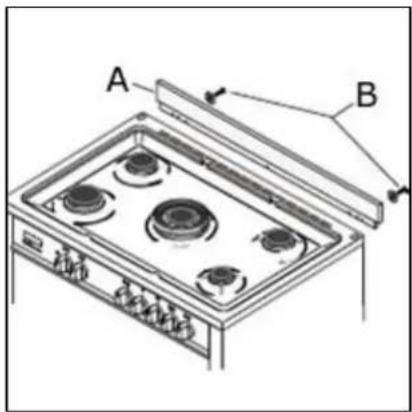
- Fix the back-guard into place by screwing the screws back into the hob with the back-guard placed in between.
Fitting the safety chain and hook
To prevent the cooker from tipping forward, two lengths of chain MUST BE fixed to the back of the oven which should be secured to the hook provided at all times.
- The hook should be secured to the wall at the back of the cooker. The chains should always be attached to the upper hook when the cooker is in position against the wall.
○ Attach the chain to the lower hook if the cooker is installed with a hose assembly so that there is no strain on the hose when the cooker is pulled forward for cleaning or maintenance.
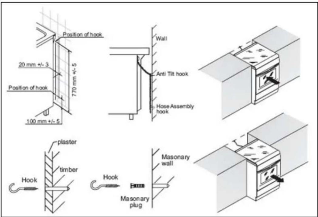
o Fix the upper hook into the wall immediately behind and to the left hand side about 770 mm from the floor.
- Secure the chain to the hook before using or cleaning the oven.
To prevent strain on the flexible hose assembly, a lower chain and hook can be fixed approximately 100 mm up from the floor.
Electrical connection

This appliance must be installed by a qualified person in accordance with the latest edition of the I.E.E. Regulations and in compliance with Baumatic's instructions.
Before connecting the appliance, make sure that the supply voltage marked on the rating plate corresponds with your mains supply voltage.
WARNING: THIS APPLIANCE MUST BE EARTHED.
- This appliance must be wired into a 20 A double pole switched fused spur outlet, having 3 mm contact separation and placed in an easily accessible position adjacent to the appliance. It should not be located above the appliance and no more than 1.25m away from it.
- The spur outlet must still be accessible even when your oven is located in its operating position.
○ Cable type: H05 RRF 3 core x 6 mm ^4
Connecting the mains supply cable
IMPORTANT
The wires in the mains lead are coloured in accordance with the following code:
GREEN AND YELLOW BLUE
EARTH
NEUTRAL
B R O W N
L I V E
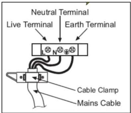
- Release the cover plate by removing the cover screw.
- Loosen the cable clamp.
- Feed the mains connection cable through the grommet in the back panel and cable clamp. Connect the mains supply cable to the terminal block on the cooker using the colour code on the previous page.
- Secure the cable clamp. Check the cable terminals for tightness and ensure that the terminal links are in place, then replace the cover plate and cover screw.
Gas connection

This appliance must be installed by a competent person in accordance with the current versions of the following UK (United Kingdom) or ROI (Republic of Ireland) Regulations and Safety Standards or their European Norm Replacements.
Important information
- This cooker is supplied to run on natural gas only and cannot be used on any other type of gas without modification.
○ Conversion for use on LPG and other gases must only be undertaken by a qualified person. For information on the use of other gases, please contact the Baumatic Technical Department. - The cooker must be installed by a qualified person, in accordance with the current edition of the Gas Safety (Installation and Use) (Amendment) Regulations and the relevant building/I.E.E. Regulations.
- Failure to install the appliance correctly could invalidate Baumatic's guarantee and lead to prosecution under the regulations quoted above.
- In the UK, GASSAFE registered installers are authorised to undertake the installation and service work, in compliance with the above regulations.
Gas Safety (Installation and Use) Regulations
- It is the law that all gas appliances are installed by competent persons in accordance with the current edition of the Gas Safety Installation and Use Regulations.
- It is in your interest and that of safety to ensure compliance with the law.
- In the UK, GASSAFE registered installers work to safe standards of practice. The cooker must also be installed in accordance with the current edition of BS 6172. Failure to install the cooker correctly could invalidate the warranty, liability claims and lead to prosecution.
- IMPORTANT: It is a requirement for a stability chain to be fitted to the appliance. Please see page 36 for more detailed information on this.
Gas connection

ALL INSTALLATION AND SERVICE WORK MUST BE CARRIED OUT BY A GASSAFE REGISTERED ENGINEER.
o Prior to installation, ensure that the gas supply conditions (nature of the gas and gas pressure) and the adjustment conditions are compatible. The adjustment conditions for this appliance are stated on the rating plate which can be found on the back cover.
- This appliance is not designed to be connected to a combustion product evacuation device. Particular attention should be given to the relevant requirements regarding ventilation.
○ IMPORTANT: THE FIBRE WASHERS MUST BE IN PLACE WHEN CONNECTING THE ADAPTOR ELBOW.
- Connect the short transition pipe to the elbow, inserting the washer. Connect the brass adapter with the test point to the nut of the transition pipe, inserting the washer. Then fix the retention device with the screw.
- Connection to the cooker should be made with an approved appliance flexible connection to BS 669.
- If the cooker has been converted for use with LPG, then it should be connected to the gas supply using an appropriate bayonet type hose. The hose MUST be suitable for use with LPG gas, these are identifiable by a red band or stripe.
○ A hose length of 0.9m to 1.25m is recommended. The length of hose chosen should be such that when the cooker is in situ, the hose does not touch the floor.
- Care should be taken to ensure that the temperature rise of areas at the rear of the cooker that are likely to come in contact with the flexible hose do not exceed 70°C.
Gas pressure may be checked on a semi-rapid hob burner. Remove the appropriate injector and attach a test nipple. Light the other burners and observe that the gas pressure complies with the gas standards in force.
- This cooker can be connected to the supply both on the right and left hand side at the rear of the cooker. To reverse the position, remove the blanking plug and refit it to the opposite side to where the hose is being connected.
Gas adjustment (Conversion to LPG for the hob top)

All work must be carried out by a GASSAFE registered engineer.
IMPORTANT: Always isolate the cooker from the electricity supply before changing the injectors and/or adjusting the minimum flow of the burners.

natural_image
Diagram of a mechanical assembly with three views (top, middle, bottom) showing internal components and directional arrows, labeled A (no text or symbols beyond labels)- Remove the pan-stands, burners and flame spreaders (A).
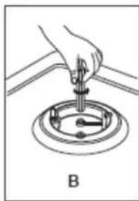
natural_image
Diagram of a hand using a tool to lift a circular component, labeled B (no text or symbols on the diagram itself)○ Unscrew the injector (B) and replace it with the stipulated injector for the new gas supply (see table below).
| Operating pressure gas | Rate Diameter injector | Heat Input (W) | By-Pass Burner | |||||
| mbar | g/h | L/h | 1/100mm | Min | Max | 1/100mm | ||
| Rapid | G30 - Butane | 28 - 30 | 218 | N/A | 88 | 800 | 3 | 000 |
| G31 - Propane | 37 | 214 | N/A | 88 | 800 | 3 | 000 | |
| G20 - Natural | 20 | N/A | 286 | 117 - Y 800 | 3000 | 44 | ||
| Semi - rapid | G30 - Butane | 28 - 30 | 131 | N/A | 68 | 600 | 1 | 800 |
| G31 - Propane | 37 | 129 | N/A | 68 | 600 | 1 | 800 | |
| G20 - Natural | 20 | N/A | 171 | 98 - Z 600 | 1800 | 34 | ||
| Auxiliary | G30 - Butane | 28 - 30 | 73 | N/A | 51 | 400 | 1 | 000 |
| G31 - Propane | 37 | 71 | N/A | 51 | 400 | 1 | 000 | |
| G20 - Natural | 20 | N/A | 95 | 75 - X 400 1000 | 28 | |||
| Triple Crown | G30 - Butane | 28 - 30 | 276 | N/A | 98 | 1400 | 3 | 800 |
| G31 - Propane | 37 | 272 | N/A | 98 | 1400 | 3 | 800 | |
| G20 - Natural | 20 | N/A | 362 | 135 - K 1400 | 3800 | 62 | ||
- Reassemble all the burners carefully; in particular you should make sure that the flame spreader is correctly placed on the burner.
IMPORTANT: After changing the injectors YOU MUST follow the minimum flow adjustment section below.
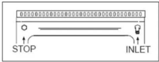
Minimum flow adjustment for hob gas taps.

All work must be carried out by a GASSAFE registered engineer.
○ Light the burner and set the knob at the minimum position.
- Remove the knob from the tap. The adjustment screw is beside the valve body.
- Place a small bladed screwdriver in the centre of the tap shaft.
- Unscrew the adjusting screw, in order to increase the gas flow or tighten the adjusting screw to decrease the gas flow.
- The correct adjustment is obtained when the flame has a length of about 3 - 4 mm.
- For butane/propane gas, the adjusting screw must be tightly screwed in.
- Refit the control knob.
○ Make sure that the flame does not go out by quickly turning from maximum flow to minimum flow. If it does then remove the control knob and make further adjustments to the gas flow, testing it again once the adjustment has been made.
○ IMPORTANT: On completion carry out a gas tightness test.
Gas tap replacement

All work must be carried out by a GASSAFE registered engineer.
IMPORTANT: Always isolate the cooker from the electricity supply before changing the gas taps.
- Remove all pan supports and burner heads.
- Unscrew the burner fixing screws (A) (four for the triple crown burner and two for all others) as shown in the diagram below:

o Pull out the knobs.
- Unscrew the six fixing screws (B) which lock the side profiles and remove it.

- Remove the hob by unscrewing the rear fixing screws (B) which lock the hob at the supports (C).
○ Unscrew the nuts (E) of the gas aluminium pipes and pull out the thermocouple quick connectors (F).
○ Unscrew the screws (D) which lock the crosspieces.

○ Unscrew the screws (G) which unite the bridles of the taps to the front frame.
- Slip the ramp towards the back part and unscrew the screws (D) in order to free the taps.
○ Change the seal each time a tap or a
thermostat is replaced. This will ensure perfect retention between the tap or a thermostat and part.
- Reassemble all the parts following the same procedure but in the reverse order.
My appliance isn't working correctly
- The oven isn't coming on.
* Check that the oven is in manual operation mode.
* Check that you have selected a cooking function and a cooking temperature.
- There appears to be no power to the oven and grill.
* Check that the appliance has been connected to the electrical mains supply correctly.
* Check that the mains fuses are in working order.
* Check that the operating instructions for setting the time of day and putting the appliance into manual operation mode have been followed.
- The grill function works but the main oven does not.
* Check that you have selected the correct cooking function.
- The grill and top oven element is not working, or cuts out for long periods of time during use.
* Allow the oven to cool for approximately 2 hours. Once cool, check whether the appliance is again working properly.
○ My food is not cooking properly
* Ensure that you are selecting the correct temperature and the correct cooking function for the food that you are cooking. It may be appropriate to adjust your cooking temperature to achieve the best cooking results.
○ My food is not cooking evenly
* Check that the oven has been installed correctly and is level.
* Check that the correct temperatures and shelf positions are being used.
- The oven light is not working
* Refer the “Replacing the oven bulb” section.
- I am getting condensation in my oven
* Steam and condensation is a natural by product of cooking any food with high water content, such as frozen food, chicken etc.
* You may get condensation in the oven cavity and forming between the oven door glasses. This is not necessarily a sign that the oven is not working correctly.
* Do not leave food in the oven to cool after it has been cooked and the oven has been switched off.
* Use a covered container, where practical, when cooking to reduce the amount of condensation that forms.

IMPORTANT: If your appliance appears not to be operating correctly, then you should disconnect it from your mains supply and then contact Baumatic Customer Care on telephone number (0118) 933 6911.
DO NOT ATTEMPT TO REPAIR THE APPLIANCE YOURSELF.
Please note that if an engineer is asked to attend whilst the product is under guarantee and finds that the problem is not the result of an appliance fault, then you may be liable for the cost of the call out charge.
The appliance must be accessible for the engineer to perform any necessary repair. If your appliance is installed in such a way that an engineer is concerned that damage will be caused to the appliance or your kitchen, then he will not complete a repair.
This includes situations where appliances have been tiled in, sealed in with sealant, have wooden obstructions placed in front of the appliance, like plinths. Or any installation other than the one specified by Baumatic Ltd. has been completed.
Please refer to the conditions of guarantee that appear on the warranty card that you receive with the appliance.
Baumatic®
United Kingdom
Baumatic Ltd.,
Baumatic Buildings,
6 Bennet Road,
Reading, Berkshire
RG2 0QX
United Kingdom
Sales Telephone
(0118) 933 6900
Sales Fax
(0118) 931 0035
Customer Care Telephone
(0118) 933 6911
Customer Care Fax
(0118) 986 9124
Spares Telephone
(01235) 437244
Advice Line Telephone
(0118) 933 6933
E-mail:
sales@baumatic.co.uk
customercare@baumatic.co.uk
spares@baumatic.co.uk
technical@baumatic.co.uk
Website:
www.baumatic.co.uk
Republic of Ireland
Service Telephone
1-890 812 724
Spares Telephone
091 756 771
Czech Republic
Baumatic CR spol s.r.o.
Lípovà 665
460 01 Liberec 4
Czech Republic
+420 483 577 200
www.baumatic.cz
Slovakia
Baumatic Slovakia, s.r.o.
Galvániho 7/D
Slovakia
+421 255 640 618
Germany
Baumatic GmbH
Lilienthalstrasse 1
320 52 Herford
Deutschland
+49 5221 694 99-0
www.baumatic.de
Italy
Baumatic Italia S.R.L.
Via Galvani N.3
35011 Campodarsego (PD)
+3904 9920 2297
www.baumatic.it
Holland
Baumatic Benelux B.V.


- INSTRUCTION MANUAL
- User Manual for your Baumatic
- BCD1020SS 100 cm BCD920SS/ BDY/ BL/ IV 90 cm
- The symbol
- Important safety information
- General Information
- Warning and safety instructions
- Child Safety
- General Safety
- Cleaning
- Installation
- Declaration of conformity
- Specifications
- BCD1020SS
- BCD920SS/ BDY/ BL/ IV
- Product specifications:
- Left oven: Multifunction oven
- Right oven: Static oven with grill
- Standard accessories:
- Optional extras:
- Electrical details
- Gas details
- Control Panel
- Cooking zone selection dial
- Thermostat control knob (main oven)
- Oven function control knob
- Thermostat control knob (secondary oven)
- Oven timer
- Setting and using the oven programmer/ timer
- Setting the time of day
- Setting the minute minder function (main and secondary oven)
- Setting the duration cooking function
- Setting the end cook function
- Setting the start and end time function
- This function will allow you to set a time in the future that the oven switches on at and a time that the oven will switch off at.
- Returning to manual operation mode
- The buzzer
- Changing or cancelling a programmed function
- Using the hob top
- Hob surface layout
- Before first use
- Lighting a burner
- Optimum use of the burners
- Hob guidelines
- Using the oven
- Using the main oven
- There are six cooking functions available on your appliance:
- Using the secondary oven
- Cooking guidelines
- Warnings
- Cooking tips
- Cooking guide for the main oven
- Cooking tips for cakes and bread
- Cooking tips for meat
- Cleaning and maintenance
- Cleaning the gas hob top
- After each use
- Cleaning the burners
- Cleaning the oven
- Replacing the oven bulb
- Flat lamps
- Round lamps
- Removing the oven door for cleaning
- Removing the inner door glass for cleaning
- Positioning
- Ventilation requirements
- Securing the back-guard
- Fitting the safety chain and hook
- Electrical connection
- WARNING: THIS APPLIANCE MUST BE EARTHED.
- Connecting the mains supply cable
- IMPORTANT
- GREEN AND YELLOW BLUE
- EARTH
- NEUTRAL
- Gas connection
- Important information
- Gas Safety (Installation and Use) Regulations
- ALL INSTALLATION AND SERVICE WORK MUST BE CARRIED OUT BY A GASSAFE REGISTERED ENGINEER.
- Gas adjustment (Conversion to LPG for the hob top)
- Gas tap replacement
- My appliance isn't working correctly
- Baumatic®
- United Kingdom
- Sales Telephone
- Sales Fax
- Customer Care Telephone
- Customer Care Fax
- Spares Telephone
- Advice Line Telephone
- E-mail:
- Website:
- Republic of Ireland
- Service Telephone
- Czech Republic
- Slovakia
- Germany
- Italy
- Holland
Brand : BAUMATIC
Model : BCD925BDY
Category : Refrigerator