SM7CN-3 - Security Camera Moog Videolarm - Free user manual and instructions
Find the device manual for free SM7CN-3 Moog Videolarm in PDF.

| Product Type | Security Camera |
| Brand | Moog Videolarm |
| Model | SM7CN-3 |
| Dimensions (W x H x D) | 150 x 120 x 90 mm (approx.) |
| Weight | 0.9 kg (approx.) |
| Power Supply | 12V DC / PoE (IEEE 802.3af) |
| Resolution | 2 MP (1920 x 1080) (typical) |
| Lens | 2.8 mm fixed lens |
| Night Vision | Up to 30 m with IR LEDs |
| Field of View | Horizontal: 90°, Vertical: 50° (approx.) |
| Ingress Protection | IP66 (weatherproof) |
| Operating Temperature | -30°C to +60°C |
| Video Compression | H.265 / H.264 |
| Motion Detection | Yes, configurable |
| Connection | Ethernet RJ-45 |
| Mounting | Wall or ceiling mount (bracket included) |
| Maintenance | Clean lens with soft, dry cloth; avoid abrasive cleaners |
| Safety | Low voltage; use only with approved power supply |
| Spare Parts | Contact Moog Videolarm support for replacement parts |
| Reparability | Not user-serviceable; refer to qualified technician |
| General Information | Manual available in PDF format on notice-facile.com |
Frequently Asked Questions - SM7CN-3 Moog Videolarm
User questions about SM7CN-3 Moog Videolarm
0 question about this device. Answer the ones you know or ask your own.
Ask a new question about this device
Download the instructions for your Security Camera in PDF format for free! Find your manual SM7CN-3 - Moog Videolarm and take your electronic device back in hand. On this page are published all the documents necessary for the use of your device. SM7CN-3 by Moog Videolarm.
USER MANUAL SM7CN-3 Moog Videolarm
© 2009, Videolarm, Inc. All Rights Reserved
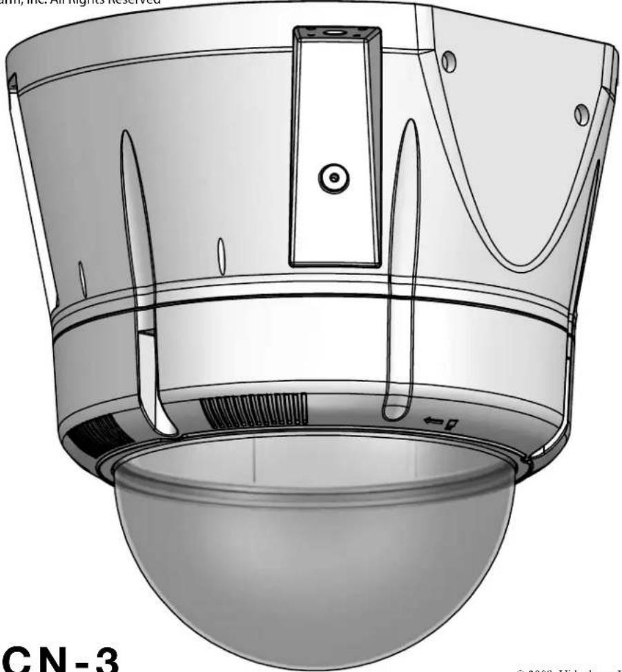
natural_image
Technical illustration of a device with a dome-shaped base and internal components (no text or symbols)SM7CN-3
© 2009. Videolarm, Inc. All Rights Reserved
SView™ Outdoor Vandal-Resistant Surface Mount Dome
www.videolarm.com
Installation and Operation Instructions for the following models:
SM7CN-3 IP Network Ready 7" Outdoor Vandal-Resistant Surface Mount PTZ Camera System - can be mounted facing down or facing towards the sky - with 36x zoom Day/ Night camera, wall mount, MPEG-4 and MJPEG video compression, full D1. Clear dome, with 24Vac input, heater/ blower
SM7CS-3 (Analog version)
IP Network Ready 7" Outdoor Vandal-Resistant Surface Mount PTZ Camera System - can be mounted facing down or facing towards the sky - with 36x zoom Day/ Night camera, wall mount, MPEG-4 and MJPEG video compression, full D1. Clear dome, with 24Vac input, heater/ blower
Before attempting to connect or operate this product, please read these instructions completely. To be used with the 81-IN5409 Instruction Manual.

CERTIFIED
81-IN5385
01-15-2009
IMPORTANT SAFEGUARDS SAFETY PRECAUTIONS
1 Read these instructions.
2 Keep these instructions.
3 Heed all warnings
4 Follow all instructions.
5 Do not use this apparatus near water.
6 Clean only with damp cloth.
7 Do not block any of the ventilation openings. Install in accordance with the manufacturers instructions.
8 Cable Runs- All cable runs must be within permissible distance.
9 Mounting - This unit must be properly and securely mounted to a supporting structure capable of sustaining the weight of the unit.
Accordingly:
a. The installation should be made by a qualified installer.
b. The installation should be in compliance with local codes.
c. Care should be exercised to select suitable hardware to install the unit, taking into account both the composition of the mounting surface and the weight of the unit.
10 Do not install near any heat sources such as radiators, heat registers, stoves, or other apparatus (including amplifiers) that produce heat.
11 Do not defeat the safety purpose of the polarized or grounding-type plug. A polarized plug has two blades with one wider than the other. A grounding type plug has two blades and a third grounding prong. The wide blade or the third prong are provided for your safety. When the provided plug does not fit into your outlet, consult an electrician for replacement of the obsolete outlet.
12 Protect the power cord from being walked on or pinched particularly at plugs, convenience receplacles, and the point where they exit from the apparatus.
13 Only use attachment/ accessories specified by the manufacturer.
14 Use only with a cart, stand, tripod, bracket, or table specified by the manufacturer, or sold with the apparatus. When a cart is used, use caution when moving the cart/ apparatus combination to avoid injury from tip-over.
15 Unplug this apparatus during lighting storms or when unused for long periods of time.
16 Refer all servicing to qualified service personnel. Servicing is required when the apparatus has been damaged in any way, such as power-supply cord or plug is damaged, liquid has been spilled of objects have fallen into the apparatus, the apparatus has been exposed to rain or moisture, does not operate normally, or has been dropped.
Be sure to periodically examine the unit and the supporting structure to make sure that the integrity of the installation is intact. Failure to comply with the foregoing could result in the unit separating from the support structure and falling, with resultant damages or injury to anyone or anything struck by the falling unit.
UNPACKING
Unpack carefully. Electronic components can be damaged if improperly handled or dropped. If an item appears to have been damaged in shipment, replace it properly in its carton and notify the shipper.
Be sure to save:
1 The shipping carton and packaging material. They are the safest material in which to make future shipments of the equipment.
2 These Installation and Operating Instructions.
SERVICE
If technical support or service is needed, contact us at the following number:
TECHNICAL SUPPORT
AVAILABLE 24 HOURS
1-800-554-1124
CAUTION
RISK OF ELECTRIC SHOCK DO NOT OPEN

CAUTION: TO REDUCE THE RISK OF ELECTRIC SHOCK, DO NOT REMOVE COVER ( OR BACK). NO USER- SERVICE-ABLE PARTS INSIDE. REFER SEVICING TO QUALIFIED SERVICE PERSONNEL.
The lightning flash with an arrowhead symbol, within an equilateral triangle, is intended to alert the user to the presence of non-insulated “dangerous voltage” within the product’s enclosure that may be of sufficient magnitude to constitute a risk to persons.
The exclamation point within an equilateral triangle is intended to alert the user to presence of important operating and maintenance (servicing) instructions in the literature accompanying the appliance.
FOR VIDEOLARM INC. PRODUCTS
VIDEOLARMINC.warrantsthisProducttobefreefromdefectsinmaterialorworkmanship,asfollows: PRODUCTCATEGORY PARTS LABOR
| All Enclosures and Electronics | Five (5) Years | Five (5) Years | ||
| Pan/Tilts | Three (3) Years | **6 months if used in autoscan /tour operation | Three (3) Years | **6 months if used in autoscan /tour operation |
| Poles/PoleEvators | Three (3) Years | Three (3) Years | ||
| Warrior/Q-View/I.R. Illuminators | Five (5) Years | Five (5) Years | ||
| SView Series | F i | **6 months if used in autoscan (5) Years | Five (5) Years | **6 months if used in autoscan /tour operation |
| Controllers | Five (5) Years | /tour operation | Five (5) Years | |
| Power Supplies | Five (5) Years | Five (5) Years | ||
| Accessory Brackets | Five (5) Years | Five (5) Years |
During the labor warranty period, to repair the Product, Purchaser will either return the defective product, freight prepaid, or deliver it to Videolarm Inc. Decatur GA. The Product to be repaired is to be returned in either its original carton or a similar package affording an equal degree of protection with a RMA # (Return Materials Authorization number) displayed on the outer box or packing slip. To obtain a RMA# you must contact our Technical Support Team at 800.554.1124, extension 101. Videolarm will return the repaired Product freight prepaid to Purchaser. Videolarm is not obligated to provide Purchaser with a substitute unit during the warranty period or at any time. After the applicable warranty period, Purchaser must pay all labor and/or parts charges.
The limited warranty stated in these product instructions is subject to all of the following terms and conditions: TERMS AND CONDITIONS
-
NOTIFICATION OF CLAIMS: WARRANTY SERVICE: If Purchaser believes that the Product is defective in material or workmanship, then written notice with an explanation of the claim shall be given promptly by Purchaser to Videolarm but all claims for warranty service must be made within the warranty period. If after investigation Videolarm determines that the reported problem was not covered by the warranty, Purchaser shall pay Videolarm for the cost of investigating the problem at its then prevailing per incident billable rate. No repair or replacement of any Product or part thereof shall extend the warranty period as to the entire Product. The specific warranty on the repaired part only shall be in effect for a period of ninety (90) days following the repair or replacement of that part or the remaining period of the Product parts warranty, whichever is greater.
-
EXCLUSIVE REMEDY: ACCEPTANCE: Purchaser's exclusive remedy and Videolarm's sole obligation is to supply (or pay for) all labor necessary to repair any Product found to be defective within the warranty period and to supply, at no extra charge, new or rebuilt replacements for defective parts.
-
EXCEPTIONS TO LIMITED WARRANTY: Videolarm shall have no liability or obligation to Purchaser with respect to any Product requiring service during the warranty period which is subjected to any of the following: abuse, improper use: negligence, accident, lightning damage or other acts of God (i.e., hurricanes, earthquakes), modification, failure of the end-user to follow the directions outlined in the product instructions, failure of the end-user to follow the maintenance procedures recommended by the International Security Industry Organization, written in product instructions, or recommended in the service manual for the Product. Furthermore, Videolarm shall have no liability where a schedule is specified for regular replacement or maintenance or cleaning of certain parts (based on usage) and the end-user has failed to follow such schedule; attempted repair by non-qualified personnel; operation of the Product outside of the published environmental and electrical parameters, or if such Product's original identification (trademark, serial number) markings have been defaced, altered, or removed. Videolarm excludes from warranty coverage Products sold AS IS and/or WITH ALL FAULTS and excludes used Products which have not been sold by Videolarm to the Purchaser. All software and accompanying documentation furnished with, or as part of the Product is furnished "AS IS" (i.e., without any warranty of any kind), except where expressly provided otherwise in any documentation or license agreement furnished with the Product.
4. PROOF OF PURCHASE: The Purchaser's dated bill of sale must be retained as evidence of the date of purchase and to establish warranty eligibility. DISCLAIMER OF WARRANTY
EXCEPT FOR THE FOREGOING WARRANTIES, VIDEOLARM HEREBY DISCLAIMS AND EXCLUDES ALL OTHER WARRANTIES, EXPRESS OR IMPLIED, INCLUDING, BUT NOT LIMITED TO ANY AND/OR ALL IMPLIED WARRANTIES OF MERCHANTABILITY, FITNESS FOR A PARTICULAR PURPOSE AND/OR ANY WARRANTY WITH REGARD TO ANY CLAIM OF INFRINGEMENT THAT MAY BE PROVIDED IN SECTION 2-312(3) OF THE UNIFORM COMMERCIAL CODE AND/OR IN ANY OTHER COMPARABLE STATE STATUTE. VIDEOLARM HEREBY DISCLAIMS ANY REPRESENTATIONS OR WARRANTY THAT THE PRODUCT IS COMPATIBLE WITH ANY COMBINATION OF NON-VIDEOLARM PRODUCTS OR NON-VIDEOLARM RECOMMENDED PRODUCTS PURCHASER CHOOSES TO CONNECT TO PRODUCT.
LIMITATION OF LIABILITY
THE LIABILITY OF VIDEOLARM, IF ANY, AND PURCHASER'S SOLE AND EXCLUSIVE REMEDY FOR DAMAGES FOR ANY CLAIM OF ANY KIND WHATSOEVER, REGARDLESS OF THE LEGAL THEORY AND WHETHER ARISING IN TORT OR CONTRACT, SHALL NOT BE GREATER THAN THE ACTUAL PURCHASE PRICE OF THE PRODUCT WITH RESPECT TO WHICH SUCH CLAIM IS MADE. IN NO EVENT SHALL VIDEOLARM BE LIABLE TO PURCHASER FOR ANY SPECIAL, INDIRECT, INCIDENTAL, OR CONSEQUENTIAL DAMAGES OF ANY KIND INCLUDING, BUT NOT LIMITED TO, COMPENSATION, REIMBURSEMENT OR DAMAGES ON ACCOUNT OF THE LOSS OF PRESENT OR PROSPECTIVE PROFITS OR FOR ANY OTHER REASON WHATSOEVER.

Electrical Specifications
SM7CN-9
SM7CS-9
Power 24VAC
Class 2 Only

80 Watts
Accessories: Heater: 50 Watts, Blower: 2 Watt
Camera Power: (See Camera Specifications): 28 Watts Max
Tools Required: .100" Flat Head Screwdriver
English
Phillips Head Screwdriver

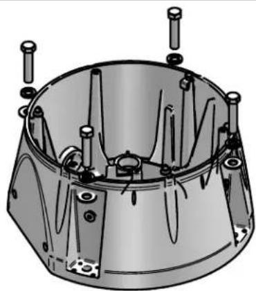
text_image
Exploded view diagram of a mechanical assembly with labeled components including a bearing, ring, and housing parts*** Pan Tilt boxed separately along with its instructions.
1
Wall
Mounting
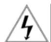
text_image
Use teflon tapeUse Teflon Tape (included) to seal conduit plugs.
- Utilice la cinta del Teflon (incluida) para sellar los enchufes del conducto.
- Utilisez la bande de teflon (incluse) pour sceller des prises de conduit.
- Benutzen Sie das Teflonklebeband (eingeschlossen) um Rohrstecker zu versiegeln.
- Use a fita adesiva do Teflon (incluída) selar plugues da canalização.
- Utilizzi il nastro del Teflon (incluso) per sigillare le spine del condotto.
2
Wall
Mounting
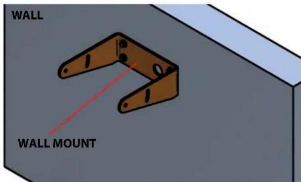
text_image
WALL WALL MOUNT
Mount only to suitable material such as brick, concrete, wood, etc. (Wall mount sold separately)
- Monte solamente al material conveniente tal como ladrillo, concreto, madera, etc. (montaje de la pared vendido por separado)
- Montez seulement au matériel approprié tel que la brique, le béton, le bois, etc..(bâti de mur vendu séparément)
- Bringen Sie nur zum verwendbaren Material wie Ziegelstein, Beton, Holz, usw. an. (Wandeinfassung separat verkauft)
- Monte somente ao material apropriado tal como o tijolo, o concreto, a madeira, etc..(montagem da parede vendida separada)
- Monti soltanto a materiale adatto quali il mattone, il calcestruzzo, il legno, ecc.
3
Wall
Mounting
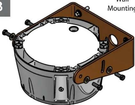
natural_image
3D technical illustration of a mechanical assembly with mounting bracket and housing (no text or symbols)
Mounting surface should be capable of rigidly ding 4(X) the weight of the entire assembly.
- La superficie de montaje debe ser capaz rígido de llevar a cabo 4(X) al peso de la asamblea entera.
- La surface de montage devrait être capable de tenir rigidement 4(X) le poids de l'assemblée entière.
- Befestigungsfläche sollte zu 4(X) das Gewicht der gesamten Versammlung steif halten fähig sein.
- A superfície de montagem deve ser capaz rígida de prender 4(X) o peso do conjunto inteiro.
- La superficie di montaggio dovrebbe essere capace rigidamente della tenuta 4(X) il peso di intero complessivo.
4
Wall
Mounting
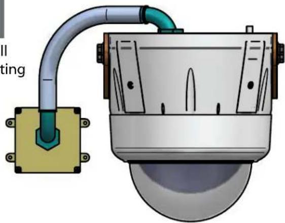
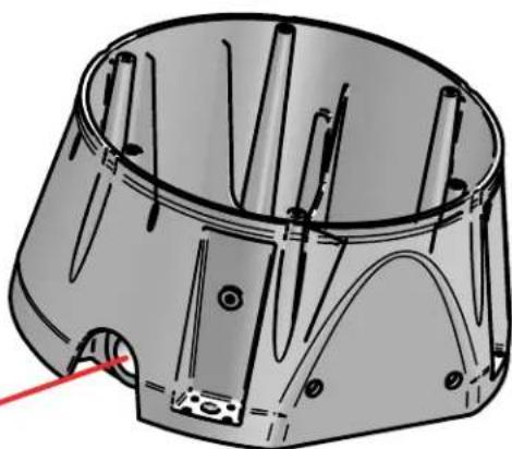
natural_image
Technical illustration of a surveillance camera with attached pipe and base (no text or symbols)Example on using conduit for wall mount applications.
- Ejemplo en usar el conducto para los usos del montaje de la pared.
- Exemple sur utiliser le conduit pour des applications de bâti de mur.
- Beispiel auf dem Verwenden des Rohres für Wandeinfassung Anwendungen.
- Exemplo em usar a canalização para aplicações da montagem da parede.
- Esempio sul per mezzo del condotto per le applicazioni del supporto della parete.
5
Surface Mounting
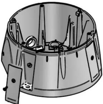
natural_image
Technical illustration of a mechanical component with internal parts and mounting holes (no text or symbols)
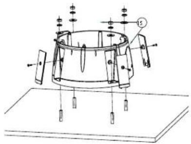
Remove the (4) side plates. Mounting Surface
should be of suitable material such as brick, concrete, wood etc.
- Quite (4) las placas laterales usando la herramienta de la seguridad proporcionada. La superficie de montaje debe estar de material conveniente tal como ladrillo, concreto, madera etc.
- Enlevez (4) les plats latéraux à l'aide de l'outil de sécurité fourni. La surface de montage devrait être de matériel approprié tel que la brique, le béton, le bois etc...
- Entfernen Sie die (4) seitlichen Platten mit dem bereitgestellten Sicherheit Werkzeug. Befestigungsmäche sollte vom verwendbaren Material wie Ziegelstein, Beton, Holz usw. sein.
- Remova (4) as placas laterais usando a ferramenta da segurança fornecida. A superfície de montagem deve ser do material apropriado tal como o tijolo, o concreto, a madeira etc..
- Rimuova (4) le piastre laterali per mezzo dell'attrezzo di sicurezza fornito. La superficie di montaggio dovrebbe essere di materiale adatto quali il mattone, il calcestruzzo, il legno ecc.
6
Surface Mounting
natural_image
Technical illustration of a mechanical component with multiple pins and mounting holes (no text or symbols)Securely mount housing to mounting surface. Replace side plates when complete.
- Con seguridad montaje que contiene a la superficie de montaje. Substituya las placas laterales cuando es completo.
- Solidement bâti logeant sur la surface de montage. Remplacez les plats latéraux si complet.
- Sicher Einfassung, die zur Befestigungsfläche unterbringt. Ersetzen Sie seitliche Platten, wenn komplett.
- Firmemente montagem que abriga à superfície de montagem. Substitua placas laterais quando completo.
- Saldamente supporto che alloggia alla superficie di montaggio. Sostituisca le piastre laterali una volta completo.
7
Surface
Mounting
natural_image
Technical line drawing of a mechanical component with multiple cylindrical pins and mounting holes (no text or symbols)Remove Cover
To connect conduit, remove conduit cover from side of housing.
- Para conectar el conducto, quite la cubierta del conducto del lado de la cubierta.
- Pour relier le conduit, enlevez la couverture de conduit du côté du logement.
- Um Rohr anzuschließen, entfernen Sie Rohrabdeckung von der Seite des Gehäuses.
- Para conectar a canalização, remova a tampa da canalização do lado da carcaça.
- Per collegare il condotto, rimuova la copertura del condotto dal lato di alloggiamento.
8
Surface
Mounting
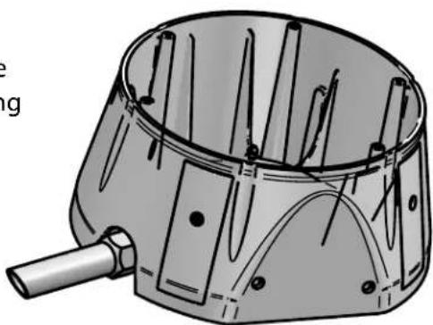
natural_image
Technical illustration of a mechanical component with internal pins and a handle (no text or symbols)Install conduit and secure with nut from inside of housing.
Make the appropriate male and female connections. Indoor model does not include pre-run cables.
- Haga las conexiones masculinas y femeninas apropiadas. El modelo de interior no incluye pre-funciona los cables.
- Établissez les rapports masculins et femelles appropriés. Le modèle d'intérieur n'inclut pas pré-courent des câbles.
- Stellen Sie die passenden männlichen und weiblichen Beziehungen her. Innenmodell schließt nicht vor-laufen lassen Kabel ein.
- Faça as conexões masculinas e fêmeas apropriadas. O modelo indoor não inclui pre-funciona cabos.
- Faccia i collegamenti maschii e femminili adatti. Il modello dell'interno non include pre-fa funzionare i cavi.
10
Wire Gauge
| Total vA consumed | ,5 | ,75 | 1,0 | 1,5 | 2,5 | 4 | 6 | MM^2 AWG |
| 22 | 20 | 18 | 16 | 14 | 12 | 10 | ||
| 5.5 | ft m | 400 121 | 600 182 | 960 292 | - | - | - | |
| 10 | 120 36.5 | 180 54.9 | 300 91.4 | 480 146 | 800 243 | 1390 396 | - | |
| 20 | 89 27.1 | 141 43.0 | 225 68.6 | 358 109 | 571 174 | 905 275 | 1440 438 | |
| 30 | 65 19.8 | 90 27.4 | 130 39.6 | 225 68.6 | 350 106 | 525 160 | 830 252 | |
| 40 | 44 13.4 | 70 21.3 | 112 14.1 | 179 54.6 | 285 86.9 | 452 138 | 720 219 | |
| 50 | 35 10.6 | 56 17.1 | 90 27.4 | 143 43.6 | 228 69.5 | 362 110 | 576 175 | |
| 60 | 29 9.4 | 47 14.3 | 75 22.9 | 119 36.2 | 190 57.9 | 301 91.7 | 480 146 | |
| 70 | 25 8.8 | 40 12.2 | 64 19.5 | 102 31.1 | 163 49.7 | 258 78.6 | 411 125 | |
| 80 | 31 7.6 | 34 10.3 | 55 16.8 | 85 25.9 | 140 42.7 | 215 65.5 | 340 103 |
These are recommended maximum distances for 24VAC with a 10% voltage drop.
- Éstos se recomiendan las distancias máximas para 24VAC con una gota del voltage del 10%.
- Ceux-ci sont recommandés des distances maximum pour 24VAC avec une baisse de volatage de 10%.
- Diese werden maximale Abstände für 24VAC mit einem das 10% volatage Tropfen empfohlen.
- Estes são recomendados distâncias máximas para 24VAC com uma gota do volatage de 10%.
- Questi sono suggeriti distanze massime per 24VAC con una goccia di volatage di 10%.
11
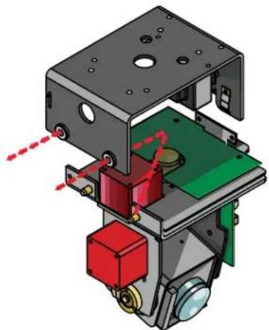
natural_image
3D mechanical assembly diagram showing internal components with red and green parts, no visible text or symbolsRemove Pan/Tilt from shipping carton. Install in base bracket in housing.
- Quite Pan/Tilt del cartón del envío. Instale en soporte bajo en la cubierta.
- Enlevez Pan/Tilt du carton d'expédition. Installez dans la parenthèse basse dans le logement.
- Entfernen Sie Pan/Tilt vom Verschiffenkarton. Bringen Sie in niedrigen Haltewinkel im Gehäuse an.
- Remova Pan/Tilt da caixa do transporte. Instale no suporte baixo na carcaça.
- Rimuova Pan/Tilt dalla scatola di trasporto. Installi in staffa bassa in alloggiamento.
12
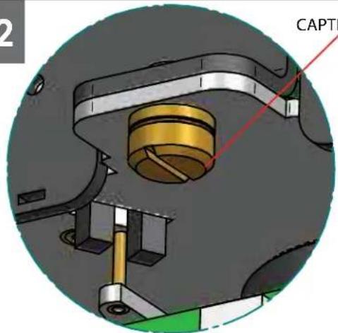
CAPTIVE SCREW
text_image
CAPTITo secure in place, tighten captive screw.
- Para asegurar en lugar, apriete el tornillo prisionero.
- Pour fixer en place, serrez la vis captive.
- Um im Platz zu sichern, ziehen Sie Sicherheitsschraube fest.
- Para fixar-se no lugar, aperte o parafuso prisioneiro.
- Per fissare sul posto, stringa la vite prigioniera.
13
text_image
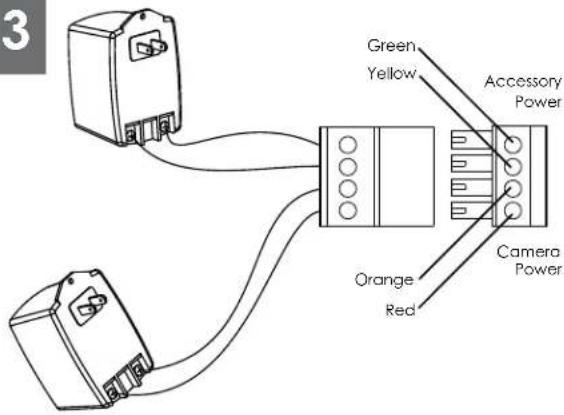
3 Green Yellow Accessory Power Orange Red Camera PowerCamera = red & orange wires to terminal Heater/Blower = yellow & green wires to terminal
- Cámara fotográfica = alambres rojos y anaranjados al terminal Heater/Blower = alambres del amarillo y del verde al terminal
- Appareil-photo = fils rouges et oranges à la borne Heater/Blower = fils de jaune et de vert à la borne
- Kamera = rote u. orange Leitungen zum Anschluß Heater/Blower = Gelb- u. Grünleitungen zum Anschluß
- Câmara = fios vermelhos & alaranjados ao terminal Heater/Blower = fios do amarelo & do verde ao terminal
- Macchina fotografica = legare rossi & arancioni al terminale Heater/Blower = legare di verde & di colore giallo al terminale
14
natural_image
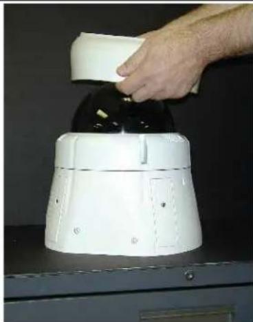
Hand pressing down a white cylindrical device on a black surface (no visible text or symbols)Use the rubber seal when mounting housing up right. Center the seal over the dome.
- Utilice el sello de goma al montar contener encima de la derecha. Centre el sello sobre la bóveda.
- Utilisez le joint en caoutchouc en montant loger vers le haut de la droite. Centrez le joint au-dessus du dôme.
- Benutzen Sie die Gummidichtung, wenn Sie die Unterbringung herauf Recht anbringen. Zentrieren Sie die Dichtung über der Haube.
- Use o selo de borracha ao montar abrigar acima da direita. Centre o selo sobre a abóbada.
- Utilizzi la guarnizione di gomma quando montano l'alloggio sulla destra. Concentrisi la guarnizione sopra la cupola.
15
natural_image
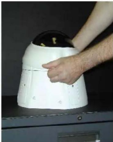
Person adjusting a white dome-shaped device on a dark surface (no visible text or symbols)Pull the seal over the face of the dome and down onto the housing.
natural_image
Person adjusting a white robotic device with black buttons on a dark surface (no visible text or symbols)Push seal edge up against dome and housing surfaces.
- Empuje el borde del sello para arriba contra superficies de la bóveda y de la cubierta.
- Poussez le bord de joint vers le haut contre des surfaces de dôme et de logement.
- Drücken Sie Dichtung Rand oben gegen Haube- und Gehäuseoberflächen.
- Empurre a borda do selo acima de encontro às superfícies da abóbada e da carcaça.
- Spinga il bordo della guarnizione in su contro le superfici dell'alloggiamento e della cupola.
17

natural_image
Close-up of a car's front wheel rim and dashboard (no visible text or symbols)Make sure there are NO GAPS or EDGES between the seal edge and the dome's surface.
- Cerciórese de que no haya BOQUETES o BORDES entre el borde del sello y la superficie de la bóveda.
- Assurez-vous qu'il n'y a AUCUNE LACUNE ou BORD entre le bord de joint et la surface du dôme.
- Stellen Sie sicher, daß es KEINE ABSTÄNDE oder RÄNDER zwischen dem Dichtung Rand und der Oberfläche der Haube gibt.
- Certifique-se que não há NENHUMA ABERTURA ou BORDA entre a borda do selo e a superfície da abóbada.
• Assicurisi che non ci sono LACUNE o BORDI fra il bordo della guarnizione e la superficie della cupola.
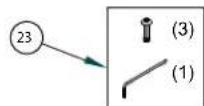
Replacement Parts List
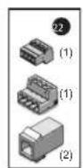
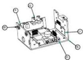
text_image
Labeled diagram of an electronic device showing internal components and numbered parts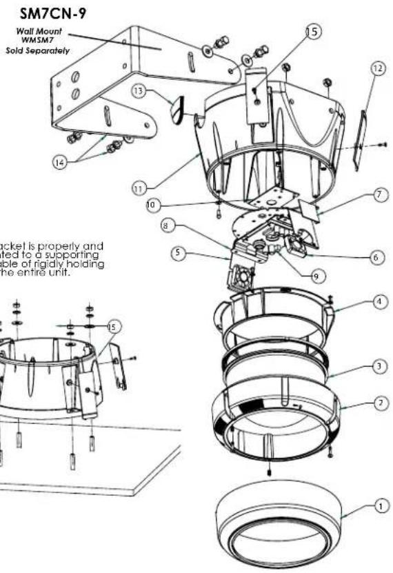
text_image
SM7CN-9 Wall Mount WM3M7 Sold Separately 15 12 13 14 11 10 8 7 5 6 9 4 3 2 1 15 screw is properly and ted to a supporting ble of rigidly holding the entire unit.| Part Number | Description | |
| 1 | RPSM7501 | DOME SEAL |
| 2 | RPRH7502 | LOWER TRIM RING |
| 3 | RC7T | TINTED REPLACEMENT CAPSULE |
| RC7C | CLEAR REPLACEMENT CAPSULE | |
| 4 | RPRH7503 | DOME CLAMPING BRACKET |
| 5 | RPFD060 | CAMERA BRACKET |
| 6 | RPFD080 | (12VDC) BLOWER (USED IN 24V HGS) |
| 7 | RPFD072 | 24VAC HEATER |
| 8 | RPNET01 | NETWORK CAMERA BRACKETS |
| 9 | RPNET02 | NETWORK HGS POWER BOARD |
| 10 | RPFD050 (Model SM7HB) | CONNECTION PCB |
| RPRH706 (Model SM7RB) | CONNECTION PCB (FIXED MODELS) | |
| RPRH707 (Model SM7NHB) | CONNECTION PCB (NETWORK MODELS) | |
| 11 | RPSM7511 | HOUSING TOP |
| 12 | RPSM7512 | MOUNTING HOLE CLOSURE |
| 13 | RPSM7513 | CONDUIT HOLE CLOSURE |
| 14 | WMSM7 (Sold Separately) | WALL MOUNT BRACKET (Sold Separately) |
| 15 | RPSM75040 | HOUSING HARDWARE |
| 16 | RPVL2857 | PAN TILT BASE BRACKET |
| 17 | RP76VL385A | PAN TILT CONNECTION PCB |
| 18 | RP96PSGK08 | PAN TILT GROMMET |
| 19 | RPVL3097 | IP CARD BRACKET |
| 20 | RP76POF060E | IP CONNECTION PCB |
| 22 | RPPKE1100 | ELECTRICAL PACKET |
| 23 | RFPKH2110 | SECURITY TOOL AND SCREW PACKET |
| 21 | RP70P14015 | IP CARD |

Be sure the bracket is properly and securely mounted to a supporting structure capable of rigidly holding the weight of the entire unit.
text_image
Technical diagram of a mechanical device with labeled components and assembly linesProduct Registration/Warranty
Thank you for choosing Videolarm. We value your patronage and are solely committed to providing you with only the highest quality products available with unmatched customer service levels that are second-to-none in the security industry.
Should a problem arise, rest assure that Videolarm stands behind its products by offering some of the most impressive warranty plans available: 3 Years on all Housings, Poles, Power Supplies, and Accessories and 5 Years on all camera systems (SView, QView, Warriors), and InfraRed Illuminators.

5
Register Your Products
Option 1: Online Option 2: Mail-In
Take a few moments and validate your purchase with our Online Product Registration Form at www.videolarm.com/productregistration.jsp or complete and mail-in the bottom portion of this flyer.
Register your recent Videolarm purchases and benefit from the following: Simple and Trouble-Free RMA process Added into customer database to receive product updates / news Eliminate the need to archive original purchase documents: Receipts, Purchase Orders, etc...

Cut at the dotted Line
Place in envelope, affix stamp and mail to: Videolarm ATTN: Warranty
2525 Park Central Ave.
Decatur, GA 30035
Main Contact Info
First Name: ____ Last Name: ____
Professional Title: Company:
Address 1: Address 2:
City: State / Province/Country:
Zip / Postal Code: ____ Phone Number:
E-mail Address:
Product Information
Please Circle One:
Business
Personal
Name & Location of Company / Store where Purchased:
(City, State, Country)
Videolarm Product ID ____ Product Description ____
Serial #
(Available only for Camera Systems, IR Illuminators, Wireless Devices)
PO#