RM7C12S-3 - Security Camera Moog Videolarm - Free user manual and instructions
Find the device manual for free RM7C12S-3 Moog Videolarm in PDF.

| Product Type | Security Camera |
| Brand | Moog Videolarm |
| Model | RM7C12S-3 |
| Dimensions (W x H x D) | Approx. 2.5 x 4.5 x 2.5 inches |
| Weight | Approx. 1.2 lbs |
| Power Supply | 12V DC, 1A |
| Image Sensor | 1/3-inch CMOS |
| Resolution | 720p HD |
| Lens | 3.6mm fixed lens |
| Night Vision | Up to 30m IR distance |
| Weatherproof Rating | IP66 |
| Operating Temperature | -30°C to 60°C |
| Mount Type | Wall or ceiling mount |
| Video Output | BNC composite |
| Main Functions | Day/night auto switch, motion detection, vandal-resistant |
| Maintenance | Clean lens with soft cloth; check housing seals |
| Safety | Do not expose to extreme voltages; disconnect power before cleaning |
| Spare Parts | Mounting bracket, power adapter, BNC cable |
| Repairability | Only qualified technicians should open the unit |
| General Information | Designed for indoor/outdoor use; manual included |
Frequently Asked Questions - RM7C12S-3 Moog Videolarm
User questions about RM7C12S-3 Moog Videolarm
0 question about this device. Answer the ones you know or ask your own.
Ask a new question about this device
Download the instructions for your Security Camera in PDF format for free! Find your manual RM7C12S-3 - Moog Videolarm and take your electronic device back in hand. On this page are published all the documents necessary for the use of your device. RM7C12S-3 by Moog Videolarm.
USER MANUAL RM7C12S-3 Moog Videolarm
© 2009, Videolarm, Inc. All Rights Reserved
natural_image
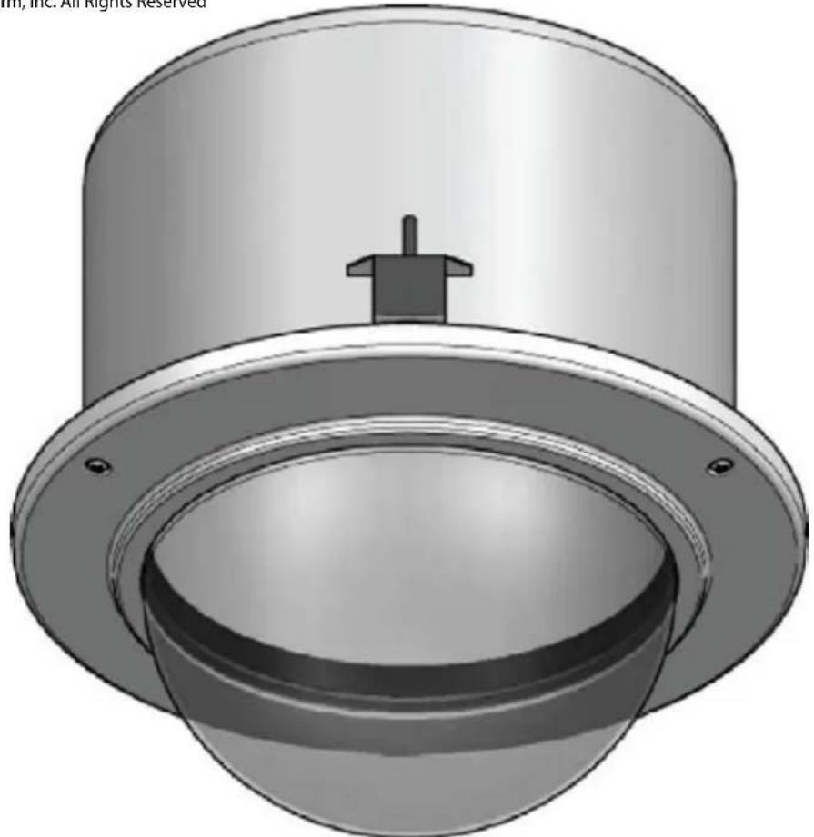
3D rendering of a mechanical component with a cylindrical top and flange, showing internal cavity and mounting holes (no text or symbols)R M 7CN-9 & RM7CS-9
Vandal-Resistant Dome Housing
www.videolarm.com
Installation and Operation Instructions for the following models:
RM7TN-9
IP Network Ready 7" Vandal-Resistant Outdoor Recessed ceiling mount dome PTZ camera system with 23x zoom day/night camera, wall mount, MPEG-4 & MJPEG video compression, Full D1. Tinted dome, with 24Vac input, heater/blower
RM7TS-9
7" Vandal-Resistant Outdoor Recessed ceiling mount dome PTZ camera system with 23x zoom day/night camera, wall mount, RS422 MOOG-Videolarm, Pelco D&P protocols. Tinted dome, with 24Vac input, heater/blower
IRM7C2N
IP Network Ready 7" Vandal-Resistant Indoor Recessed ceiling mount dome PTZ camera system with 23x zoom day/night MPEG-4 & MJPEG video compression, Full D1, Tinted dome
IRM7TS-9
7" Vandal-Resistant Indoor Recessed ceiling mount dome PTZ camera system with 23x zoom day/night camera, wall mount, MOOG-Videolarm, Pelco D&P protocols. Tinted dome
Before attempting to connect or operate this product, please read these instructions completely. To be used with the 81-IN5409 Instruction Manual.

CERTIFIED
81-IN5401
01-29-2009
IMPORTANT SAFEGUARDS SAFETY PRECAUTIONS
1 Read these instructions.
2 Keep these instructions.
3 Heed all warnings
4 Follow all instructions.
5 Do not use this apparatus near water.
6 Clean only with damp cloth.
7 Do not block any of the ventilation openings. Install in accordance with the manufacturers instructions.
8 Cable Runs- All cable runs must be within permissible distance.
9 Mounting - This unit must be properly and securely mounted to a supporting structure capable of sustaining the weight of the unit.
Accordingly:
a. The installation should be made by a qualified installer.
b. The installation should be in compliance with local codes.
c. Care should be exercised to select suitable hardware to install the unit, taking into account both the composition of the mounting surface and the weight of the unit.
10 Do not install near any heat sources such as radiators, heat registers, stoves, or other apparatus (including amplifiers) that produce heat.
11 Do not defeat the safety purpose of the polarized or grounding-type plug. A polarized plug has two blades with one wider than the other. A grounding type plug has two blades and a third grounding prong. The wide blade or the third prong are provided for your safety. When the provided plug does not fit into your outlet, consult an electrician for replacement of the obsolete outlet.
12 Protect the power cord from being walked on or pinched particularly at plugs, convenience receplacles, and the point where they exit from the apparatus.
13 Only use attachment/ accessories specified by the manufacturer.
14 Use only with a cart, stand, tripod, bracket, or table specified by the manufacturer, or sold with the apparatus. When a cart is used, use caution when moving the cart/ apparatus combination to avoid injury from tip-over.
15 Unplug this apparatus during lighting storms or when unused for long periods of time.
16 Refer all servicing to qualified service personnel. Servicing is required when the apparatus has been damaged in any way, such as power-supply cord or plug is damaged, liquid has been spilled of objects have fallen into the apparatus, the apparatus has been exposed to rain or moisture, does not operate normally, or has been dropped.
Be sure to periodically examine the unit and the supporting structure to make sure that the integrity of the installation is intact. Failure to comply with the foregoing could result in the unit separating from the support structure and falling, with resultant damages or injury to anyone or anything struck by the falling unit.
UNPACKING
Unpack carefully. Electronic components can be damaged if improperly handled or dropped. If an item appears to have been damaged in shipment, replace it properly in its carton and notify the shipper.
Be sure to save:
1 The shipping carton and packaging material. They are the safest material in which to make future shipments of the equipment.
2 These Installation and Operating Instructions.
SERVICE
If technical support or service is needed, contact us at the following number:
TECHNICAL SUPPORT
AVAILABLE 24 HOURS
1-800-554-1124

text_image
CAUTION RISK OF ELECTRIC SHOCK DO NOT OPEN CAUTION: TO REDUCE THE RISK OF ELECTRIC SHOCK, DO NOT REMOVE COVER ( OR BACK). NO USER- SERVICE- ABLE PARTS INSIDE. REFER SEVICING TO QUALIFIED SERVICE PERSONNEL.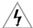
The lightning flash with an arrowhead symbol, within an equilateral triangle, is intended to alert the user to the presence of non-insulated “dangerous voltage” within the product's enclosure that may be of sufficient magnitude to constitute a risk to persons.
The exclamation point within an equilateral triangle is intended to alert the user to presence of important operating and maintenance (servicing) instructions in the literature accompanying the appliance.
| PRODUCTCATEGORY PARTS | LABOR | |||
| All Enclosures and Electronics | Five (5) Years | Five (5) Years | ||
| Pan/Tilts | Three (3) Years **6 months if used in autoscan /tour operation | Three (3) Years | **6 months if used in autoscan /tour operation | |
| Poles/PoleEvators | Three (3) Years | Three (3) Years | ||
| Warrior/Q-View/I.R. Illuminators | Five (5) Years | Five (5) Years | ||
| SView Series | F i **6 months if used in autoscan (5) Years | Five (5) Years | **6 months if used in autoscan /tour operation | |
| Controllers | Five (5) Years /tour operation | Five (5) Years | ||
| Power Supplies | Five (5) Years | Five (5) Years | ||
| Accessory Brackets | Five (5) Years | Five (5) Years | ||
During the labor warranty period, to repair the Product, Purchaser will either return the defective product, freight prepaid, or deliver it to Videolarm Inc. Decatur GA. The Product to be repaired is to be returned in either its original carton or a similar package affording an equal degree of protection with a RMA # (Return Materials Authorization number) displayed on the outer box or packing slip. To obtain a RMA# you must contact our Technical Support Team at 800.554.1124, extension 101. Videolarm will return the repaired Product freight prepaid to Purchaser. Videolarm is not obligated to provide Purchaser with a substitute unit during the warranty period or at any time. After the applicable warranty period, Purchaser must pay all labor and/or parts charges.
The limited warranty stated in these product instructions is subject to all of the following terms and conditions:
TERMS AND CONDITIONS
-
NOTIFICATION OF CLAIMS: WARRANTY SERVICE: If Purchaser believes that the Product is defective in material or workmanship, then written notice with an explanation of the claim shall be given promptly by Purchaser to Videolarm but all claims for warranty service must be made within the warranty period. If after investigation Videolarm determines that the reported problem was not covered by the warranty, Purchaser shall pay Videolarm for the cost of investigating the problem at its then prevailing per incident billable rate. No repair or replacement of any Product or part thereof shall extend the warranty period as to the entire Product. The specific warranty on the repaired part only shall be in effect for a period of ninety (90) days following the repair or replacement of that part or the remaining period of the Product parts warranty, whichever is greater.
-
EXCLUSIVE REMEDY: ACCEPTANCE: Purchaser's exclusive remedy and Videolarm's sole obligation is to supply (or pay for) all labor necessary to repair any Product found to be defective within the warranty period and to supply, at no extra charge, new or rebuilt replacements for defective parts.
-
EXCEPTIONS TO LIMITED WARRANTY: Videolarm shall have no liability or obligation to Purchaser with respect to any Product requiring service during the warranty period which is subjected to any of the following: abuse, improper use: negligence, accident, lightning damage or other acts of God (i.e., hurricanes, earthquakes), modification, failure of the end-user to follow the directions outlined in the product instructions, failure of the end-user to follow the maintenance procedures recommended by the International Security Industry Organization, written in product instructions, or recommended in the service manual for the Product. Furthermore, Videolarm shall have no liability where a schedule is specified for regular replacement or maintenance or cleaning of certain parts (based on usage) and the end-user has failed to follow such schedule; attempted repair by non-qualified personnel; operation of the Product outside of the published environmental and electrical parameters, or if such Product's original identification (trademark, serial number) markings have been defaced, altered, or removed. Videolarm excludes from warranty coverage Products sold AS IS and/or WITH ALL FAULTS and excludes used Products which have not been sold by Videolarm to the Purchaser. All software and accompanying documentation furnished with, or as part of the Product is furnished "AS IS" (i.e., without any warranty of any kind), except where expressly provided otherwise in any documentation or license agreement furnished with the Product.
-
PROOF OF PURCHASE: The Purchaser's dated bill of sale must be retained as evidence of the date of purchase and to establish warranty eligibility.
DISCLAIMEROF WARRANTY
EXCEPT FOR THE FOREGOING WARRANTIES, VIDEOLARM HEREBY DISCLAIMS AND EXCLUDES ALL OTHER WARRANTIES, EXPRESS OR IMPLIED, INCLUDING, BUT NOT LIMITED TO ANY AND/OR ALL IMPLIED WARRANTIES OF MERCHANTABILITY, FITNESS FOR A PARTICULAR PURPOSE AND/OR ANY WARRANTY WITH REGARD TO ANY CLAIM OF INFRINGEMENT THAT MAY BE PROVIDED IN SECTION 2-312(3) OF THE UNIFORM COMMERCIAL CODE AND/OR IN ANY OTHER COMPARABLE STATE STATUTE. VIDEOLARM HEREBY DISCLAIMS ANY REPRESENTATIONS OR WARRANTY THAT THE PRODUCT IS COMPATIBLE WITH ANY COMBINATION OF NON-VIDEOLARM PRODUCTS OR NON-VIDEOLARM RECOMMENDED PRODUCTS PURCHASER CHOOSES TO CONNECT TO PRODUCT.
LIMITATION OF LIABILITY
THE LIABILITY OF VIDEOLARM, IF ANY, AND PURCHASER'S SOLE AND EXCLUSIVE REMEDY FOR DAMAGES FOR ANY CLAIM OF ANY KIND WHATSOEVER, REGARDLESS OF THE LEGAL THEORY AND WHETHER ARISING IN TORT OR CONTRACT, SHALL NOT BE GREATER THAN THE ACTUAL PURCHASE PRICE OF THE

Electrical Specifications
Power 24VAC
Class 2 Only
RM7TN-9
RM7TS-9
IRM7TN-9 (INDOOR ONLY)
IRM7TS-9 (INDOOR ONLY)
24 VAC

English
3.3 Amps
Total Power: 80 Watts
Accessories: Heater: 50 Watts/Blower: 2 Watts
Camera Power: 28 Watts
Tools Required: .100" Flat Head Screwdriver
Phillips Head Screwdriver
Note: IRM7CN includes no accessories
24 VAC

Español
3.3 amperios
Puissance D'Apparell-photo : 28 watts
Tournevis Principal Phillips
Poder Total: 80 watts
Acessórios: Colefator: 50 Watts/Blower: 2 watt
text_image
Exploded view diagram of a mechanical assembly with labeled components and exploded view*** Pan Tilt boxed separately along with its instructions.
1
text_image
10.375"Using the provided template, mark the ceiling tile for the cutout.
- Con la plantilla proporcionada, cortar el azulejo del techo para el agujero.
- En utilisant le calibre fourni, marquez la tuile de plafond pour le coupe-circuit.
- Mit der zur Verfügung gestellten Schablone kennzeichnen Sie die Decke Fliese für den Ausschnitt.
- Usando o molde fornecido, marque a telha do teto para o entalhe.
- Usando la mascherina fornita, contrassegni le mattonelle del soffitto per il ritaglio.
2
natural_image
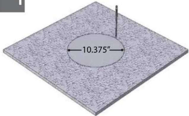
3D diagram of a mechanical component with a central hole and a rectangular slot, placed on a textured base (no text or symbols)A box cutter or jigsaw can be used for cutting the circle.
natural_image
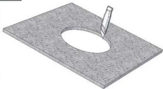
3D rendering of a mechanical component mounted on a textured base, with a screwdriver inserted (no text or symbols visible)Place the housing in the tile and secure the outer tabs.
natural_image
3D rendering of a mechanical component with a cylindrical body and attached pin, mounted on a textured base (no text or symbols visible)Connect the flex conduit to the housing.
- Conecte el conducto de la flexión con la cubierta.
- Reliez le conduit de câble au logement.
- Schließen Sie das Flexrohr an das Gehäuse an.
- Conecte a canalização do cabo flexível à carcaça.
• Colleghi il condotto della flessione all'alloggiamento.
5
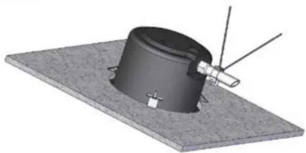
natural_image
3D rendering of a cylindrical mechanical component mounted on a flat base with antennas and a small protrusion (no text or symbols visible)Add the safety wire to the flex conduit or continue to the next step.
- Agregue el alambre de seguridad al conducto de la flexión o continúe al paso siguiente.
- Ajoutez le fil de sûreté au conduit de câble ou continuez à la prochaine étape.
- Fügen Sie die Sicherheit Leitung dem Flexrohr hinzu oder fahren Sie zum folgenden Schritt fort.
- Adicione o fio de segurança à canalização do cabo flexível ou continue à etapa seguinte.
- Aggiunga il legare di sicurezza al condotto della flessione o continui al punto seguente.
6
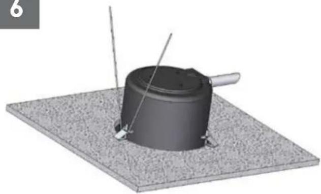
natural_image
3D rendering of a cylindrical mechanical component mounted on a textured base, with two wires extending outward (no text or symbols visible)The alternate location to attach the safety wire is on the housing secure tab.
- La localización alterna para unir el alambre de seguridad está en la lengüeta segura de la cubierta.
- L'endroit alternatif pour attacher le fil de sûreté est sur l'étiquette bloquée de logement.
• Die wechselnde Position, zum der Sicherheit Leitung anzubringen ist auf dem sicheren Vorsprung des Gehäuses. - A posição alterna para unir o fio de segurança está na aba segura da carcaça.
- La posizione alternata per fissare il legare di sicurezza è sulla linguetta sicura dell'alloggiamento.
7
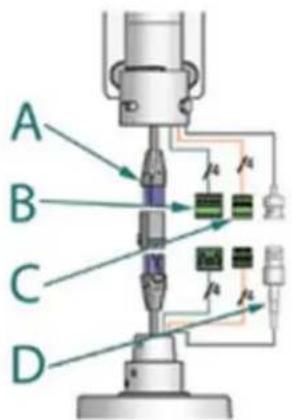
text_image
A B C DA
B
| 24VAC | POWER | ||
| 1 | Camera | Red | Max 28 Watts |
| 2 | Camera | Orange | |
| 3 | Heater/Blower | Yellow | 52 Watts(Outdoor Only) |
| 4 | Heater/Blower | Green | |
C
D
| 1/0 | ||
| 1 | GND | Blue |
| 2 | GND | Violet |
| 3 | Alarm OUT | Gray |
| 4 | Alarm IN | White |
BNC
Make the appropriate male and female connections.
- Haga las conexiones masculinas y femeninas apropiadas.
- Établissez les rapports masculins et femelles appropriés.
- Stellen Sie die passenden männlichen und weiblichen Beziehungen her.
- Faça as conexões masculinas e fêmeas apropriadas.
- Faccia i collegamenti maschii e femminili adatti.
8
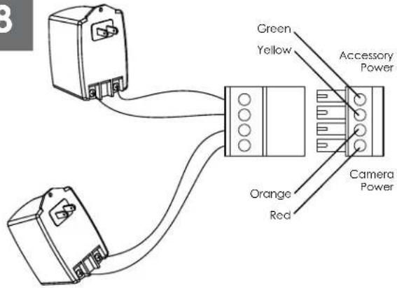
text_image
Green Yellow Accessory Power Orange Red Camera PowerCamera = red & orange wires to terminal Heater/Blower = yellow & green wires to terminal
- Cámara fotográfica = alambres rojos y anaranjados al terminal Heater/Blower = alambres del amarillo y del verde al terminal
- Appareil-photo = fils rouges et oranges à la borne Heater/Blower = fils de jaune et de vert à la borne
- Kamera = rote u. orange Leitungen zum Anschluß Heater/Blower = Gelb- u. Grünleitungen zum Anschluß
- Câmera = fios vermelhos & alaranjados ao terminal Heater/Blower = fios do amarelo & do verde ao terminal
- Macchina fotografica = legare rossi & arancioni al terminale Heater/Blower = legare di verde & di colore giallo al terminale
192
Wire Gauge
| Total vA consumed | ,5 | ,75 | 1,0 | 1,5 | 2,5 | 4 | 6 | MM^2 |
| 22 | 20 | 18 | 16 | 14 | 12 | 10 | AWG | |
| 5.5 | ftm | 400121 | 600182 | 960292 | - | - | - | |
| 10 | 12036.5 | 18054.9 | 30091.4 | 480146 | 800243 | 1390396 | - | |
| 20 | 8927.1 | 14143.0 | 22568.6 | 358109 | 571174 | 905275 | 1440438 | |
| 30 | 6519.8 | 9027.4 | 13039.6 | 22568.6 | 350106 | 525160 | 830252 | |
| 40 | 4413.4 | 7021.3 | 11214.1 | 17954.6 | 28586.9 | 452138 | 720219 | |
| 50 | 3510.6 | 5617.1 | 9027.4 | 14343.6 | 22869.5 | 362110 | 576175 | |
| 60 | 299.4 | 4714.3 | 7522.9 | 11936.2 | 19057.9 | 30191.7 | 480146 | |
| 70 | 258.8 | 4012.2 | 6419.5 | 10231.1 | 16349.7 | 25878.6 | 411125 | |
| 80 | 317.6 | 3410.3 | 5516.8 | 8525.9 | 14042.7 | 21565.5 | 340103 |
These are recommended maximum distances for 24VAC with a 10% voltage drop.
- Éstos se recomiendan las distancias máximas para 24VAC con una gota del voltage del 10%.
- Ceux-ci sont recommandés des distances maximum pour 24VAC avec une chute de tension de 10%.
- Diese werden maximale Abstände für 24VAC mit einem 10% Spannungsabfall empfohlen.
- Estes são recomendados distâncias máximas para 24VAC com uma queda de tensão de 10%.
- Questi sono suggeriti distanze massime per 24VAC con una differenza de potenziale di 10%.
10
natural_image
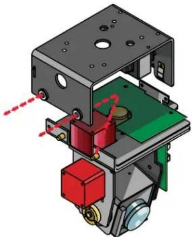
3D mechanical assembly diagram showing internal components with red and green parts, no visible text or symbolsRemove Pan/Tilt from shipping carton. Install in base bracket in housing.
- Quite Pan/Tilt del cartón del envío. Instale en soporte bajo en la cubierta.
- Enlevez Pan/Tilt du carton d'expédition. Installez dans la parenthèse basse dans le logement.
- Entfernen Sie Pan/Tilt vom Verschiffenkarton. Bringen Sie in niedrigen Haltewinkel im Gehäuse an.
- Remova Pan/Tilt da caixa do transporte. Instale no suporte baixo na carcaça.
- Rimuova Pan/Tilt dalla scatola di trasporto. Installi in staffa bassa in alloggiamento.
11
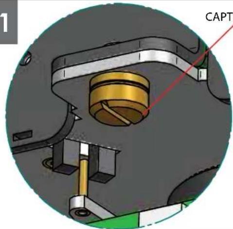
CAPTIVE SCREW
natural_image
Mechanical assembly diagram showing a cylindrical component inserted into a housing, with no visible text or symbols.To secure in place, tighten captive screw.
- Para asegurar en lugar, apriete el tornillo prisionero.
- Pour fixer en place, serrez la vis captive.
- Um im Platz zu sichern, ziehen Sie Sicherheitsschraube fest.
- Para fixar-se no lugar, aperte o parafuso prisioneiro.
- Per fissare sul posto, stringa la vite prigioniera.
12
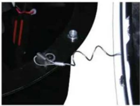
natural_image
Close-up of a medical or laboratory setup with wires and components, no visible text or symbolsHook the lanyard from the dome to the housing as shown.
- Enganche el acollador de la bóveda a la cubierta según lo demostrado.
- Accrochez la lanière du dôme au logement comme montré.
- Spannen Sie die Abzuglinie von der Haube zum Gehäuse an, wie gezeigt.
- Enganche o colhedor da abóbada à carcaça como mostrada.
- Agganci la cordicella dalla cupola all'alloggiamento come indicato.
13
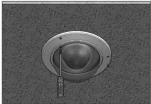
natural_image
Close-up of a ceiling-mounted screwdriver inserted into a circular opening (no text or symbols visible)Secure the dome in place (alternate security screws are provided).
- Asegure la bóveda en lugar (se proporcionan los tornillos alternos de la seguridad).
- Fixez le dôme en place (des vis alternatives de sécurité sont fournies).
- Sichern Sie die Haube im Platz (wechselnde Sicherheit Schrauben werden zur Verfügung gestellt).
- Fixe a abóbada no lugar (os parafusos alternos da segurança são fornecidos).
- Fissi la cupola sul posto (le viti alternate di sicurezza sono fornite).
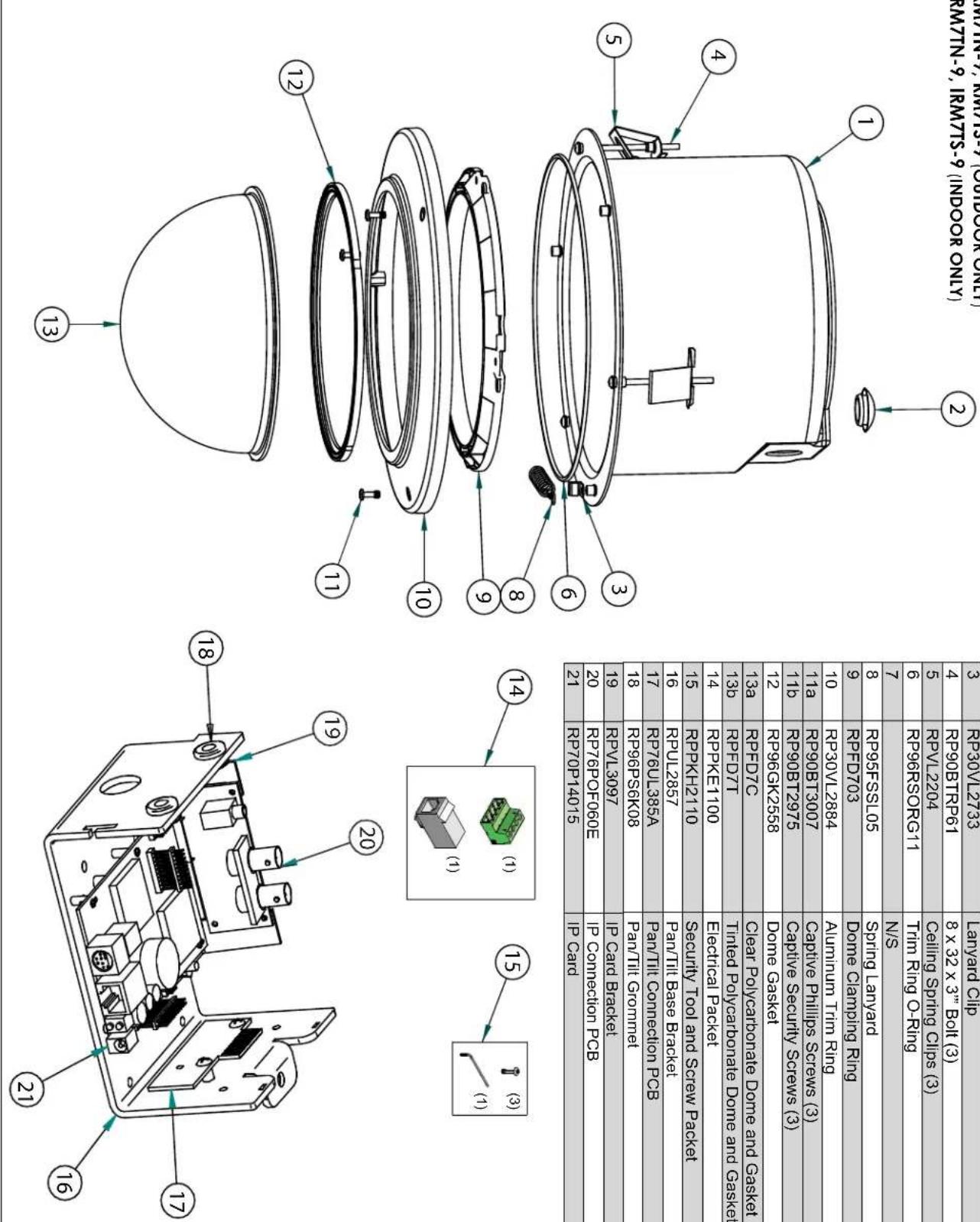
| DESCRIPTION | REPLACEMENT PARTS NUMBER |
| 1 | RP30VL2873 |
| 2 | RP |
| 3 | RP30VL2733 |
| 4 | RP90BTTRP61 |
| 5 | RPVL2204 |
| 6 | RP96RSORG11 |
| 7 | N/S |
| 8 | RP95FSSL05 |
| 9 | RPDF703 |
| 10 | RP30VL2884 |
| 11a | RP90BT3007 |
| 11b | RP90BT2975 |
| 12 | RP96GK2558 |
| 13a | RPDF7C |
| 14 | RPKKET100 |
| 15 | RPKKH2110 |
| 16 | RPUJ2857 |
| 17 | RP76UL385A |
| 18 | RP96PS6K08 |
| 19 | RPVL3097 |
| 20 | RP76POF060E |
| 21 | RP70P14015 |
Replacement Parts List
RM7TN-9, RM7TS-9 (OUTDOOR ONLY) IRM7TN-9, IRM7TS-9 (INDOOR ONLY)
Product Registration/Warranty
Thank you for choosing Videolarm. We value your patronage and are solely committed to providing you with only the highest quality products available with unmatched customer service levels that are second-to-none in the security industry.
Should a problem arise, rest assure that Videolarm stands behind its products by offering some of the most impressive warranty plans available: 3 Years on all Housings, Poles, Power Supplies, and Accessories and 5 Years on all camera systems (SView, QView, Warriors), and InfraRed Illuminators.

5
Register Your Products
Option 1: Online Option 2: Mail-In
Take a few moments and validate your purchase with our Online Product Registration Form at www.videolarm.com/productregistration.jsp or complete and mail-in the bottom portion of this flyer.
Register your recent Videolarm purchases and benefit from the following: Simple and Trouble-Free RMA process Added into customer database to receive product updates / news Eliminate the need to archive original purchase documents: Receipts, Purchase Orders, etc...

Cut at the dotted Line
Place in envelope, affix stamp and mail to: Videolarm ATTN: Warranty
2525 Park Central Ave.
Decatur, GA 30035
Main Contact Info
First Name: Last Name:
Professional Title: Company:
Address 1: Address 2:
City: State / Province/Country:
Zip / Postal Code: ____ Phone Number: ____ E-mail Address: ____
Product Information
Please Circle One: Business Personal
Name & Location of Company / Store where Purchased: ____
(City, State, Country)
Videolarm Product ID ____ Product Description ____
Serial #
(Available only for Camera Systems, IR Illuminators, Wireless Devices)
PO#