PFD7TN-3 - Security Camera Moog Videolarm - Free user manual and instructions
Find the device manual for free PFD7TN-3 Moog Videolarm in PDF.

User questions about PFD7TN-3 Moog Videolarm
0 question about this device. Answer the ones you know or ask your own.
Ask a new question about this device
Download the instructions for your Security Camera in PDF format for free! Find your manual PFD7TN-3 - Moog Videolarm and take your electronic device back in hand. On this page are published all the documents necessary for the use of your device. PFD7TN-3 by Moog Videolarm.
USER MANUAL PFD7TN-3 Moog Videolarm
© 2009, Videolarm, Inc. All Rights Reserved
natural_image
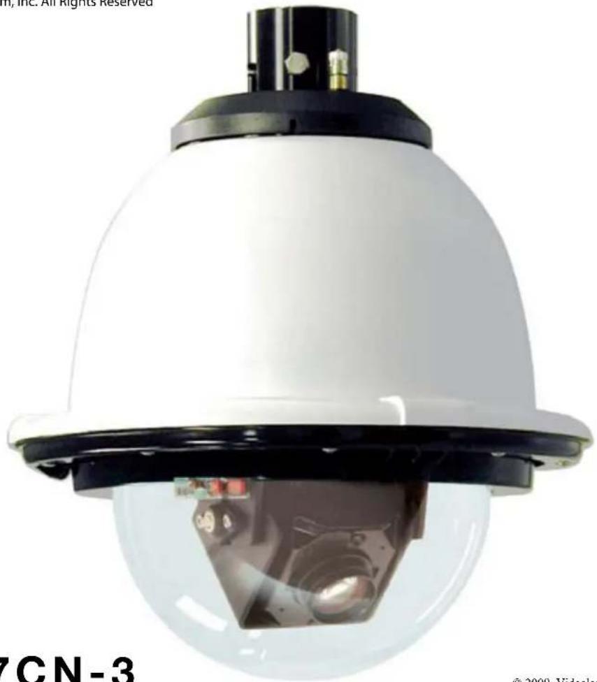
Close-up of a white spherical security camera with reflective lens, no visible text or symbols on the device itself.PFD7CN-3
© 2009. Videolarm, Inc. All Rights Reserved
SView™ Outdoor Pressurized FusionDome
www.videolarm.com
Installation and Operation Instructions for the following models:
PFD7CN-3 IP Network Ready 7" Pressurized Outdoor PTZ Camera System with 36x zoom compression, full D1. Clear dome, with 24Vac input, heater/ blower
PFD7CS-3 (Analog version) IP Network Ready 7" Pressurized Outdoor PTZ Camera System with 36x zoom compression, full D1. Clear dome, with 24Vac input, heater/ blower
Before attempting to connect or operate this product, please read these instructions completely. To be used with the 81-IN5409 Instruction Manual.

CERTIFIED
81-IN5382
01-15-2009
IMPORTANT SAFEGUARDS SAFETY PRECAUTIONS
1 Read these instructions.
2 Keep these instructions.
3 Heed all warnings
4 Follow all instructions.
5 Do not use this apparatus near water.
6 Clean only with damp cloth.
7 Do not block any of the ventilation openings. Install in accordance with the manufacturers instructions.
8 Cable Runs- All cable runs must be within permissible distance.
9 Mounting - This unit must be properly and securely mounted to a supporting structure capable of sustaining the weight of the unit.
Accordingly:
a. The installation should be made by a qualified installer.
b. The installation should be in compliance with local codes.
c. Care should be exercised to select suitable hardware to install the unit, taking into account both the composition of the mounting surface and the weight of the unit.
10 Do not install near any heat sources such as radiators, heat registers, stoves, or other apparatus (including amplifiers) that produce heat.
11 Do not defeat the safety purpose of the polarized or grounding-type plug. A polarized plug has two blades with one wider than the other. A grounding type plug has two blades and a third grounding prong. The wide blade or the third prong are provided for your safety. When the provided plug does not fit into your outlet, consult an electrician for replacement of the obsolete outlet.
12 Protect the power cord from being walked on or pinched particularly at plugs, convenience receptacles, and the point where they exit from the apparatus.
13 Only use attachment/ accessories specified by the manufacturer.
14 Use only with a cart, stand, tripod, bracket, or table specified by the manufacturer, or sold with the apparatus. When a cart is used, use caution when moving the cart/ apparatus combination to avoid injury from tip-over.
15 Unplug this apparatus during lighting storms or when unused for long periods of time.
16 Refer all servicing to qualified service personnel. Servicing is required when the apparatus has been damaged in any way, such as power-supply cord or plug is damaged, liquid has been spilled of objects have fallen into the apparatus, the apparatus has been exposed to rain or moisture, does not operate normally, or has been dropped.
Be sure to periodically examine the unit and the supporting structure to make sure that the integrity of the installation is intact. Failure to comply with the foregoing could result in the unit separating from the support structure and falling, with resultant damages or injury to anyone or anything struck by the falling unit.
UNPACKING
Unpack carefully. Electronic components can be damaged if improperly handled or dropped. If an item appears to have been damaged in shipment, replace it properly in its carton and notify the shipper.
Be sure to save:
1 The shipping carton and packaging material. They are the safest material in which to make future shipments of the equipment.
2 These Installation and Operating Instructions.
SERVICE
If technical support or service is needed, contact us at the following number:
TECHNICAL SUPPORT
AVAILABLE 24 HOURS
1-800-554-1124
CAUTION
RISK OF ELECTRIC SHOCK DO NOT OPEN

CAUTION: TO REDUCE THE RISK OF ELECTRIC SHOCK, DO NOT REMOVE COVER ( OR BACK). NO USER- SERVICE-ABLE PARTS INSIDE. REFER SEVICING TO QUALIFIED SERVICE PERSONNEL.
The lightning flash with an arrowhead symbol, within an equilateral triangle, is intended to alert the user to the presence of non-insulated “dangerous voltage” within the product's enclosure that may be of sufficient magnitude to constitute a risk to persons.
The exclamation point within an equilateral triangle is intended to alert the user to presence of important operating and maintenance (servicing) instructions in the literature accompanying the appliance.
FOR VIDEOLARM INC. PRODUCTS
VIDEOLARMINC.warrantsthisProducttobefreefromdefectsinmaterialorworkmanship,asfollows: PRODUCTCATEGORY PARTS LABOR
| All Enclosures and Electronics | Five (5) Years | Five (5) Years | ||
| Pan/Tilts | Three (3) Years | **6 months if used in autoscan /tour operation | Three (3) Years | **6 months if used in autoscan /tour operation |
| Poles/PoleEvators | Three (3) Years | Three (3) Years | ||
| Warrior/Q-View/I.R. Illuminators | Five (5) Years | Five (5) Years | ||
| SView Series | F i | **6 months if used in autoscan (5) Years | Five (5) Years | **6 months if used in autoscan /tour operation |
| Controllers | Five (5) Years | /tour operation | Five (5) Years | |
| Power Supplies | Five (5) Years | Five (5) Years | ||
| Accessory Brackets | Five (5) Years | Five (5) Years |
During the labor warranty period, to repair the Product, Purchaser will either return the defective product, freight prepaid, or deliver it to Videolarm Inc. Decatur GA. The Product to be repaired is to be returned in either its original carton or a similar package affording an equal degree of protection with a RMA # (Return Materials Authorization number) displayed on the outer box or packing slip. To obtain a RMA# you must contact our Technical Support Team at 800.554.1124, extension 101. Videolarm will return the repaired Product freight prepaid to Purchaser. Videolarm is not obligated to provide Purchaser with a substitute unit during the warranty period or at any time. After the applicable warranty period, Purchaser must pay all labor and/or parts charges.
The limited warranty stated in these product instructions is subject to all of the following terms and conditions: TERMS AND CONDITIONS
-
NOTIFICATION OF CLAIMS: WARRANTY SERVICE: If Purchaser believes that the Product is defective in material or workmanship, then written notice with an explanation of the claim shall be given promptly by Purchaser to Videolarm but all claims for warranty service must be made within the warranty period. If after investigation Videolarm determines that the reported problem was not covered by the warranty, Purchaser shall pay Videolarm for the cost of investigating the problem at its then prevailing per incident billable rate. No repair or replacement of any Product or part thereof shall extend the warranty period as to the entire Product. The specific warranty on the repaired part only shall be in effect for a period of ninety (90) days following the repair or replacement of that part or the remaining period of the Product parts warranty, whichever is greater.
-
EXCLUSIVE REMEDY: ACCEPTANCE: Purchaser's exclusive remedy and Videolarm's sole obligation is to supply (or pay for) all labor necessary to repair any Product found to be defective within the warranty period and to supply, at no extra charge, new or rebuilt replacements for defective parts.
-
EXCEPTIONS TO LIMITED WARRANTY: Videolarm shall have no liability or obligation to Purchaser with respect to any Product requiring service during the warranty period which is subjected to any of the following: abuse, improper use: negligence, accident, lightning damage or other acts of God (i.e., hurricanes, earthquakes), modification, failure of the end-user to follow the directions outlined in the product instructions, failure of the end-user to follow the maintenance procedures recommended by the International Security Industry Organization, written in product instructions, or recommended in the service manual for the Product. Furthermore, Videolarm shall have no liability where a schedule is specified for regular replacement or maintenance or cleaning of certain parts (based on usage) and the end-user has failed to follow such schedule; attempted repair by non-qualified personnel; operation of the Product outside of the published environmental and electrical parameters, or if such Product's original identification (trademark, serial number) markings have been defaced, altered, or removed. Videolarm excludes from warranty coverage Products sold AS IS and/or WITH ALL FAULTS and excludes used Products which have not been sold by Videolarm to the Purchaser. All software and accompanying documentation furnished with, or as part of the Product is furnished "AS IS" (i.e., without any warranty of any kind), except where expressly provided otherwise in any documentation or license agreement furnished with the Product.
4. PROOF OF PURCHASE: The Purchaser's dated bill of sale must be retained as evidence of the date of purchase and to establish warranty eligibility. DISCLAIMER OF WARRANTY
EXCEPT FOR THE FOREGOING WARRANTIES, VIDEOLARM HEREBY DISCLAIMS AND EXCLUDES ALL OTHER WARRANTIES, EXPRESS OR IMPLIED, INCLUDING, BUT NOT LIMITED TO ANY AND/OR ALL IMPLIED WARRANTIES OF MERCHANTABILITY, FITNESS FOR A PARTICULAR PURPOSE AND/OR ANY WARRANTY WITH REGARD TO ANY CLAIM OF INFRINGEMENT THAT MAY BE PROVIDED IN SECTION 2-312(3) OF THE UNIFORM COMMERCIAL CODE AND/OR IN ANY OTHER COMPARABLE STATE STATUTE. VIDEOLARM HEREBY DISCLAIMS ANY REPRESENTATIONS OR WARRANTY THAT THE PRODUCT IS COMPATIBLE WITH ANY COMBINATION OF NON-VIDEOLARM PRODUCTS OR NON-VIDEOLARM RECOMMENDED PRODUCTS PURCHASER CHOOSES TO CONNECT TO PRODUCT.
LIMITATION OF LIABILITY
THE LIABILITY OF VIDEOLARM, IF ANY, AND PURCHASER'S SOLE AND EXCLUSIVE REMEDY FOR DAMAGES FOR ANY CLAIM OF ANY KIND WHATSOEVER, REGARDLESS OF THE LEGAL THEORY AND WHETHER ARISING IN TORT OR CONTRACT, SHALL NOT BE GREATER THAN THE ACTUAL PURCHASE PRICE OF THE PRODUCT WITH RESPECT TO WHICH SUCH CLAIM IS MADE. IN NO EVENT SHALL VIDEOLARM BE LIABLE TO PURCHASER FOR ANY SPECIAL, INDIRECT, INCIDENTAL, OR CONSEQUENTIAL DAMAGES OF ANY KIND INCLUDING, BUT NOT LIMITED TO, COMPENSATION, REIMBURSEMENT OR DAMAGES ON ACCOUNT OF THE LOSS OF PRESENT OR PROSPECTIVE PROFITS OR FOR ANY OTHER REASON WHATSOEVER.

Electrical Specifications
Power 24VAC
Class 2 Only
PFD7CN-9
PFD7CS-9

3.3 Amps
Total Power: 80 Watts
Accessories: Heater: 50 Watts/Blower: 2 Watts
Camera Power: 28 Watts
Tools Required: .100" Flat Head Screwdriver
English
Phillips Head Screwdriver
7/16" Wrench or Socket
24 VAC

3.3 amperios
Tournevis Principal Phillips
24 VAC

3.3 Ampere
Poder Total: 80 watts
text_image
Diagram illustrating a step-by-step assembly of a mechanical component with labeled parts and directional arrows indicating motion.*** Pan Tilt boxed separately along with its instructions.
1
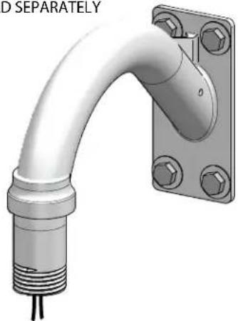
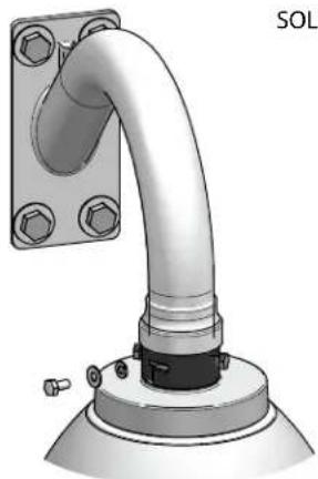
SOLD SEPARATELY
natural_image
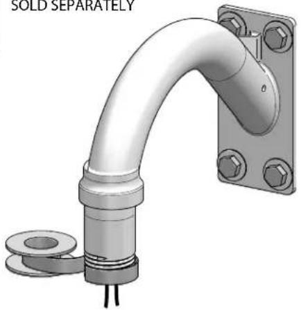
3D rendering of a metallic pipe fitting with mounting flange and threaded end (no text or symbols)Securely mount bracket to wall. Pull wiring through bracket and position grommet as shown.
- Con seguridad soporte del montaje a emparedar. Tire del cableado a través del soporte y del ojal de la posición según lo demostrado.
- Solidement parenthèse de bâti à murer. Tirez le câblage par la parenthèse et le canon isolant de position comme montré.
- Sicher Einfassung Haltewinkel wall. Ziehen Sie Verdraftung durch Haltewinkel und Position Gummimuffe, wie gezeigt.
- Firmemente suporte da montagem a wall. Puxe a fiação através do suporte e do ilhó da posição como mostrado.
- Saldamente staffa del supporto da wall. Tiri i collegamenti tramite la staffa ed il gommino di protezione di posizione come indicato.
2
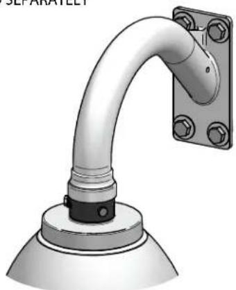
SOLD SEPARATELY
natural_image
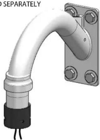
3D rendering of a pipe fitting with mounting bracket and side connectors (no text or symbols)Wrap Teflon tape around the pipe threads to ensure a tight seal.
- La cinta del Teflon del abrigo alrededor de la pipa rosca para asegurar un sello apretado.
- La bande de teflon d'enveloppe autour de la pipe filète pour assurer un joint serré.
- Verpackung Teflonklebeband um das Rohr verlegt, um eine feste Dichtung sicherzustellen.
- A fita adesiva do Teflon do envoltório em torno da tubulação enfia para assegurar um selo apertado.
- Il nastro del Teflon dell'involucro intorno al tubo filetta per accertare una guarnizione stretta.
3
SOLD SEPARATELY
natural_image
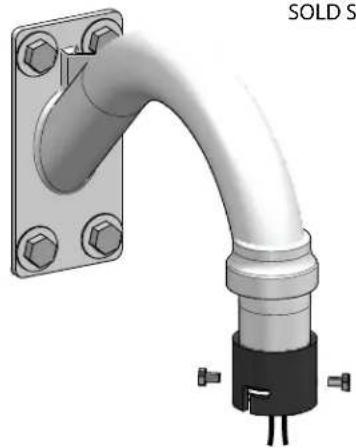
3D rendering of a pipe fitting with a separate mounting bracket (no text or symbols visible)Screw the coupling onto the pipe threads until it is hand tight.
- Atornille el acoplador sobre los hilos de rosca de la pipa hasta que es mano firmemente.
- Vissez le couplage sur les fils de pipe jusqu'à ce que ce soit main fortement.
- Schrauben Sie die Koppelung auf die Rohrgewinde, bis es Hand fest ist.
- Parafuse o acoplamento nas linhas da tubulação até que esteja mão firmemente.
- Avviti l'accoppiamento sui filetti del tubo fino a che non sia fortemente mano.
4
SOLD SEPARATELY
natural_image
3D rendering of a pipe fitting with mounting flange and connector (no text or symbols)Screw the (2) bolts into the coupling.
- Atornille (2) los pernos en el acoplador.
- Vissez (2) les boulons dans l'accouplement.
- Schrauben Sie die (2) Schraubbolzen in die Koppelung.
- Parafuse (2) os parafusos no acoplamento.
• Avviti (2) i bulloni nell'accoppiamento.
5
SOLD SEPARATELY
natural_image
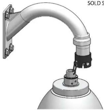
3D rendering of a mechanical arm or support structure with a dome base and mounting bracket (no text or symbols visible)Loop the lanyard over the set screw to temporarily hold housing.
- Coloque el acollador sobre el tornillo de presión para celebrar temporalmente la cubierta.
- Faites une boucle la lanière au-dessus de la vis de réglage pour tenir temporairement le logement.
- Schlingen Sie die Abzuglinie über der Klemmschraube, um Gehäuse vorübergehend zu halten.
- Dê laços no colhedor sobre o parafuso de fixação para prender temporariamente a carcaça.
- Colleghi la cordicella in circuito sopra la vite di arresto temporaneamente per tenere l'alloggiamento.
6
SOLD SEPARATELY
natural_image
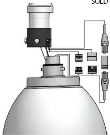
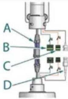
Technical diagram of a mechanical assembly with labeled components (no readable text or symbols)Make the appropriate wiring connections from the dome to the gooseneck.
- Haga las conexiones apropiadas del cableado de la bóveda al gooseneck.
- Établissez les rapports appropriés de câblage à partir du dôme au col de cygne.
- Stellen Sie die passenden Verdrahtung Beziehungen von der Haube zum gooseneck her.
- Faça as conexões apropriadas da fiação da abóbada ao gooseneck.
- Faccia i collegamenti adatti dei collegamenti dalla cupola al gooseneck.
7
SOLD SEPARATELY
natural_image
3D rendering of a pipe fitting mounted on a base with mounting flanges (no text or symbols visible)Undo the lanyard, pull housing up and twist secure with the locking bolt and washers.
- Deshaga el acollador, tire de contener para arriba y fuerza seguro con el perno y las arandelas de fijación.
- Défaites la lanière, tirez loger vers le haut et tordez bloqué avec le boulon et les rondelles de fermeture.
- Annulieren Sie die Abzuglinie, ziehen Sie oben unterbringen und verdrehen Sie sicheres mit dem verriegelnschraubbolzen und den Unterlegscheiben.
- Undo o colhedor, puxe abrigar acima e força seguro com o parafuso e as arruelas travando.
- Undo la cordicella, firi l'alloggio in su e torca sicuro con il bullone e le rondelle di bloccaggio.
8
SOLD SEPARATELY
natural_image
3D rendering of a pipe fitting mounted on a base with mounting flanges (no text or symbols visible)Slide the grommet down over the coupling to prevent water from entering and complete the assembly.
- Resbale el ojal abajo sobre el acoplador para evitar que el agua entre y para terminar a la asamblea.
- Glissez le canon isolant vers le bas au-dessus de l'accouplement pour empêcher l'eau d'entrer et pour accomplir l'assemblée.
- Schieben Sie die Gummimuffe unten über der Koppelung, um zu verhindern, daß Wasser und die Versammlung durchzuführen hereinkommt.
- Deslize o ilhó para baixo sobre o acoplamento para impedir que a água entre e para terminar o conjunto.
- Faccia scorrere il gommino di protezione giù sopra l'accoppiamento per impedire l'acqua entrare e per completare il complessivo.
9
Wire as shown below for IP models:(PFD7CN-9; PFD7TN-9)
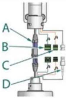
text_image
A B C DA B
RJ45
| 24VAC | SNC-RZ50/SNC-RZ30 | ||
| 1 | Camera/Heater/Blower | Yellow | 2B Watts |
| 2 | Camera/Heater/Blower | Green | |
| 52 Watts | |||
C
| 1/0 | ||
| 1 | Alarm 1 | Blue |
| 2 | Common | Violet |
D
| RJ45 |
Make the appropriate male and female connections. Indoor model does not include pre-run cables.
- Haga las conexiones masculinas y femeninas apropiadas. El modelo de interior no incluye pre-funciona los cables.
- Établissez les rapports masculins et femelles appropriés. Le modèle d'intérieur n'inclut pas pré-courent des câbles.
- Stellen Sie die passenden männlichen und weiblichen Beziehungen her. Innenmodell schließt nicht vor-laufen lassen Kabel ein.
- Faça as conexões masculinas e fêmeas apropriadas. O modelo indoor não inclui pre-funciona cabos.
- Faccia i collegamenti maschii e femminili adatti. Il modello dell'interno non include pre-fa funzionare i cavi.
10
Wire as shown below for analog models: (PFD7CS-9; PFD7TS-9)
text_image
A B C DA
| 24VAC | SNC-RZ50/SNC-RZ30 | ||
| 1 | Camera/Heater/Blower | Yellow | 13 Watts |
| 2 | Camera/Heater/Blower | Green | |
| 52 Watts | |||
C
| 1/0 | ||
| 1 | RS-48SRX A | Blue |
| 2 | RS-48SRX B | Violet |
| 3 | RS-48STX A | Gray |
| 4 | RS-48STX B | White |
Make the appropriate male and female connections. Indoor model does not include pre-run cables.
- Haga las conexiones masculinas y femeninas apropiadas. El modelo de interior no incluye pre-funciona los cables.
- Établissez les rapports masculins et femelles appropriés. Le modèle d'intérieur n'inclut pas pré-courent des câbles.
- Stellen Sie die passenden männlichen und weiblichen Beziehungen her. Innenmodell schließt nicht vor-laufen lassen Kabel ein.
- Faça as conexões masculinas e fêmeas apropriadas. O modelo indoor não inclui pre-funciona cabos.
- Faccia i collegamenti maschii e femminili adatti. Il modello dell'interno non include pre-fa funzionare i cavi.
12
Wire Gauge
| Total vA consumed | ,5 | ,75 | 1,0 | 1,5 | 2,5 | 4 | 6 | MM^2 |
| 22 | 20 | 18 | 16 | 14 | 12 | 10 | AWG | |
| 5.5 | ft/m | 400/121 | 600/182 | 960/292 | - | - | - | |
| 10 | 120/36.5 | 180/54.9 | 300/91.4 | 480/146 | 800/243 | 1300/396 | - | |
| 20 | 89/27.1 | 141/43.0 | 225/68.6 | 358/109 | 571/174 | 905/275 | 1440/438 | |
| 30 | 65/19.8 | 90/27.4 | 130/39.6 | 225/68.6 | 350/106 | 525/160 | 830/252 | |
| 40 | 44/13.4 | 70/21.3 | 112/34.1 | 179/54.6 | 285/86.9 | 452/138 | 720/219 | |
| 50 | 35/10.6 | 56/17.1 | 90/27.4 | 143/43.6 | 228/69.5 | 362/110 | 576/175 | |
| 60 | 29/9.4 | 47/14.3 | 75/22.9 | 119/36.2 | 190/57.9 | 301/91.7 | 480/146 | |
| 70 | 25/8.8 | 40/12.2 | 64/19.5 | 102/31.1 | 163/49.7 | 258/78.6 | 411/125 | |
| 80 | 31/7.6 | 34/10.3 | 55/16.8 | 85/25.9 | 140/42.7 | 215/65.5 | 340/103 |
These are recommended maximum distances for 24VAC with a 10% voltage drop.
- Éstos se recomiendan las distancias máximas para 24VAC con una gota del voltage del 10%.
- Ceux-ci sont recommandés des distances maximum pour 24VAC avec une chute de tension de 10%.
- Diese werden maximale Abstände für 24VAC mit einem 10% Spannungsabfall empfohlen.
- Estes são recomendados distâncias máximas para 24VAC com uma queda de tensão de 10%.
- Questi sono suggeriti distanze massime per 24VAC con una differenza de potenziale di 10%.
12
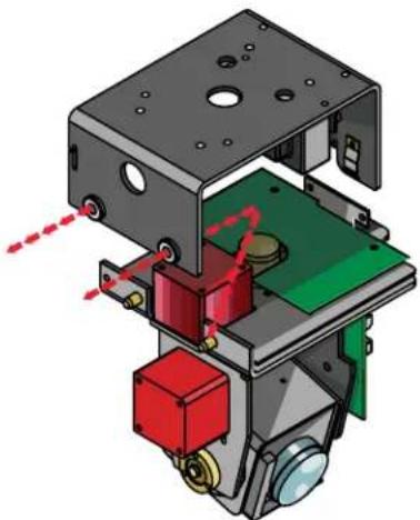
natural_image
3D mechanical assembly diagram showing internal components with red and green parts, no visible text or symbolsRemove Pan/Tilt from shipping carton. Install in base bracket in housing.
- Quite Pan/Tilt del cartón del envío. Instale en soporte bajo en la cubierta.
- Enlevez Pan/Tilt du carton d'expédition. Installez dans la parenthèse basse dans le logement.
- Entfernen Sie Pan/Tilt vom Verschiffenkarton. Bringen Sie in niedrigen Haltewinkel im Gehäuse an.
- Remova Pan/Tilt da caixa do transporte. Instale no suporte baixo na carcaça.
- Rimuova Pan/Tilt dalla scatola di trasporto. Installi in staffa bassa in alloggiamento.
13
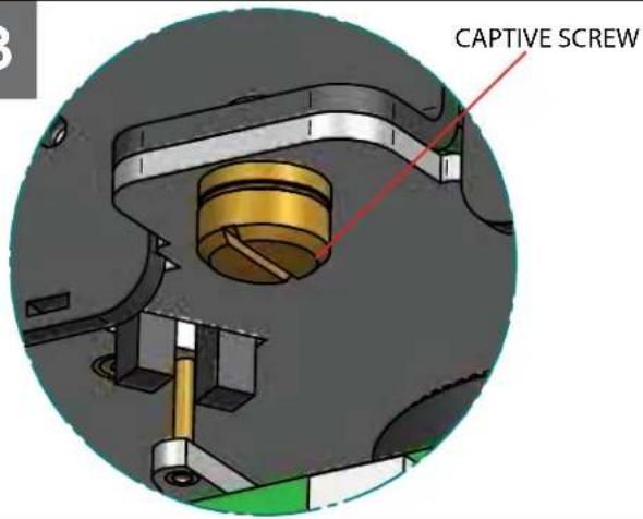
text_image
CAPTIVE SCREWTo secure in place, tighten captive screw.
- Para asegurar en lugar, apriete el tornillo prisionero.
- Pour fixer en place, serrez la vis captive.
- Um im Platz zu sichern, ziehen Sie Sicherheitsschraube fest.
- Para fixar-se no lugar, aperte o parafuso prisioneiro.
• Per fissare sul posto, stringa la vite prigioniera.
14
natural_image
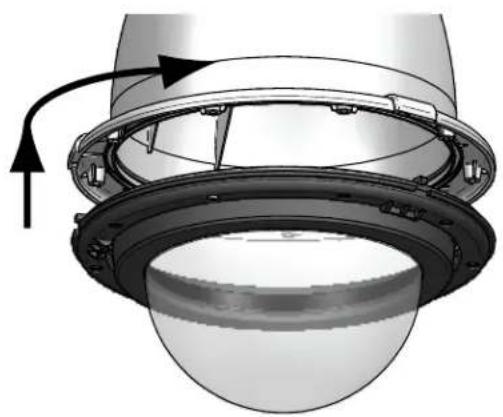
Technical diagram of a mechanical component with a curved arrow indicating direction (no text or symbols present)To install the dome align the tabs and twist counter clockwise to secure.
natural_image
Technical illustration of a helmet with a screwdriver inserted, showing no text or symbolsHand tighten the screws on the dome. Recommended torque 12 inches/lb (1.35Nm).
- La mano aprieta los tornillos en la bóveda. Esfuerzo de torsión recomendado 12 inches/lb (el 1.35Nm).
- La main serrent les vis sur le dôme. Couple recommandé 12 inches/lb (1.35Nm).
- Hand ziehen die Schrauben an der Haube fest. Empfohlene Drehkraft 12 inches/lb (1.35Nm).
- A mão aperta os parafusos na abóbada. Torque recomendado 12 inches/lb (1.35Nm).
- La mano stringe le viti sulla cupola. Coppia di torsione suggerita 12 inches/lb (1.35Nm).
16
text_image
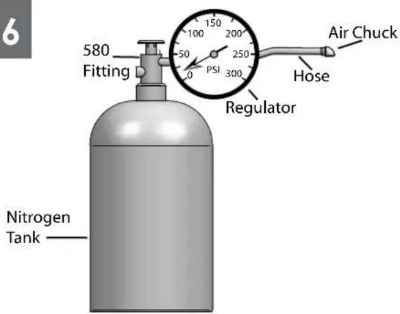
6 580 Fitting PSI Regulator Air Chuck Hose Nitrogen TankWhen pressurizing unit be sure to set the guage or regulator from 10-20psi (.7-1.4bar).
- Al presurizar la unidad sea seguro fijar la medida o el regulador de 10-20psi (7-1.4bar).
- En pressurisant l'unité soyez sûr de placer la jauge ou le régulateur de 10-20psi (7-1.4bar).
- Wenn Sie Maßeinheit unter Druck setzen, seien Sie sicher, das Eichmaß oder den Regler von 10-20psi (7-1.4bar) einzustellen.
- Ao pressurizar a unidade seja certo ajustar o guage ou o regulador de 10-20psi (7-1.4bar).
- Nel pressurizzare l'unità sia sicuro regolare il misuratore o il regolatore da 10-20psi (7-1.4bar).
17
text_image
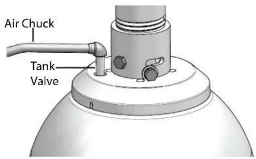
Air Chuck Tank ValvePlace the air chuck on the tank valve and begin filling until pressure relief valve opens.
- Coloque la tirada del aire en la válvula del tanque y comience a llenar hasta que la válvula de descarga de presión se abre.
- Placez le mandrin d'air sur la valve de réservoir et commencez à remplir jusqu'à ce que la valve de décompression s'ouvre.
- Setzen Sie die Luftklemme auf das Behälterventil und fangen Sie an zu füllen, bis Druckablaßventil sich öffnet.
- Coloque o mandril do ar na válvula do tanque e comece a encher-se até que a válvula de escape de pressão abra.
- Disponga il mandrino dell'aria sulla valvola del carro armato e cominci a riempirsi fino a che la valvola limitatrice della pressione non si apra.
18
natural_image
Illustration of a laboratory setup with a pipette and test tube (no text or symbols)Open the relief valve. Drain all air from the housing and repeat twice to remove all moisture.
- Abra la válvula de descarga. Drene todo el aire de la cubierta y de la repetición dos veces para quitar toda la humedad.
- Ouvrez la soupape de sécurité. Évacuez tout l'air le logement et la répétition deux fois pour enlever toute l'humidité.
- Öffnen Sie das Sicherheitsventil. Lassen Sie alle Luft aus dem Gehäuse und der Wiederholung zweimal ab, um alle Feuchtigkeit zu entfernen.
- Abra a válvula de escape. Drene todo o ar da carcaça e do repeat duas vezes para remover toda a umidade.
- Apra la valvola di sfiato. Vuoti due volte tutta l'aria dall'alloggiamento e dalla ripetizione per rimuovere tutta l'umidità.
text_image
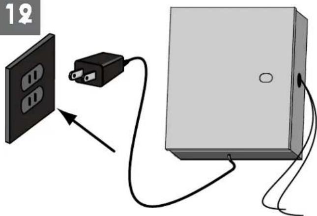
12Power up the unit.
- Energía encima de la unidad.
- Puissance vers le haut de l'unité.
- Energie herauf die Maßeinheit.
- Poder acima da unidade.
- Alimentazione sull'unità.
20
text_image
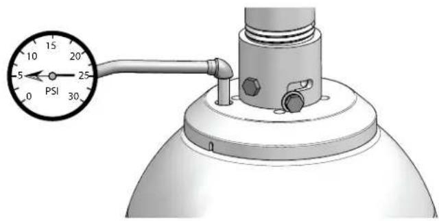
10 15 20 25 0 PSI 30After purging check the housing pressure. It should be around 5psi (.34bar).
- Después de purgar el cheque la presión de la cubierta. Debe estar alrededor de 5psi (34bar).
- Après la purge du contrôle la pression de logement. Elle devrait être autour de 5psi (34bar).
- Nachdem Überprüfung der Gehäusedruck bereinigt worden ist. Sie sollte um 5psi (34bar) sein.
- Após ter removido a verificação a pressão da carcaça. Deve ser em torno de 5psi (34bar).
- Dopo l'eliminazione dell'inceppo del controllo la pressione dell'alloggiamento. Dovrebbe essere intorno a 5psi (34bar).
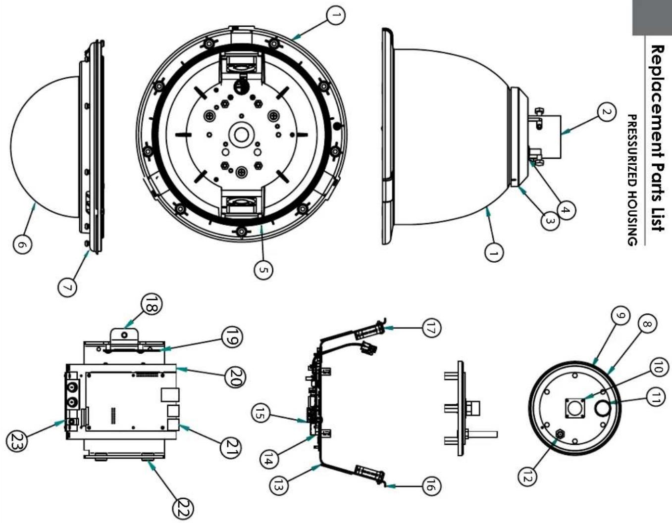
| 1 RPFDTO2 Housing Top (Extended) | ||
| 2 RPVL1938 Removable P/ndent Coupling | ||
| 3 RPVL1802 Plastic Rain Shroud | ||
| 4 RPVL1795 Tank Valve Gasket | ||
| 5 RP6RSORG11 Main O- Ring 9.25" | ||
| 6 RPFDTR01 Trim Ring w/o Dome | ||
| 7 RGPFD7 Clear Dome with sealing O-Ring | ||
| 8 RPFDTO3 Internal Sealing Bracket Assembly | ||
| 9 RP6RSORG10 Small O- Ring 4.5" | ||
| 10 RP70PTO7A Hermetic Conector, Basket, Cable | ||
| 11 RP95VALV08 5 to 7 psi Pressure Relief Valve | ||
| 12 RP95VALV07 Tank Valve | ||
| 13 RPFD072 24VAC Heater | ||
| 14 RP46PKH3063 Saccers Packet | ||
| 15 RPFD050 Connection PCB | ||
| 16 RPFD060 Main Bracket Assembly | ||
| 17 RPFD080 Blower | ||
| N/S | RP40CAPPFD811 | External Input Video/Power Cables (Network Models Only) |
| N/S | RP46PKH2200 | Packet Assembly-Hardware |
| 20 RPVL3097 IP Card Bracket (Network Models Only) | ||
| 21 RP70P14015 IP Card (Network Models Only) | ||
| 22 RP96PSGK08 P/T Grimmel (2) | ||
| 23 RP76P0F060E IP Connection Card | ||
| N/S | WM20G | GOOSE NICK (Solid SEPARATELY) |
Part No. Description
Product Registration/Warranty
Thank you for choosing Videolarm. We value your patronage and are solely committed to providing you with only the highest quality products available with unmatched customer service levels that are second-to-none in the security industry.
Should a problem arise, rest assure that Videolarm stands behind its products by offering some of the most impressive warranty plans available: 3 Years on all Housings, Poles, Power Supplies, and Accessories and 5 Years on all camera systems (SView, QView, Warriors), and InfraRed Illuminators.

Register Your Products

Option 1: Online Option 2: Mail-In
Take a few moments and validate your purchase with our Online Product Registration Form at www.videolarm.com/productregistration.jsp or complete and mail-in the bottom portion of this flyer.
Register your recent Videolarm purchases and benefit from the following: Simple and Trouble-Free RMA process Added into customer database to receive product updates / news Eliminate the need to archive original purchase documents: Receipts, Purchase Orders, etc...

Cut at the dotted Line
Place in envelope, affix stamp and mail to: Videolarm ATTN: Warranty
2525 Park Central Ave.
Decatur, GA 30035
Main Contact Info
First Name: Last Name:
Professional Title: Company:
Address 1: Address 2:
City: State / Province/Country:
Zip / Postal Code: ____ Phone Number:
E-mail Address:
Product Information
Please Circle One: Business Personal
Name & Location of Company / Store where Purchased: ____
(City, State, Country)
Videolarm Product ID ____ Product Description ____
Serial #
(Available only for Camera Systems, IR Illuminators, Wireless Devices)
PO#