FDP7C12N-3 - Security Camera Moog Videolarm - Free user manual and instructions
Find the device manual for free FDP7C12N-3 Moog Videolarm in PDF.

| Product Type | Security Camera |
| Brand | Moog Videolarm |
| Model | FDP7C12N-3 |
| Sensor Resolution | 7 Megapixels (estimated) |
| Lens Type | Fixed focal lens, 3.6mm (estimated) |
| Night Vision | Up to 30m (IR LEDs) |
| Video Compression | H.265, H.264 |
| Power Supply | 12V DC or PoE (802.3af) |
| Power Consumption | Max 10W |
| Dimensions (DxH) | 150mm x 100mm (estimated) |
| Weight | Approx. 500g |
| Weatherproof Rating | IP67 (estimated) |
| Operating Temperature | -30°C to 60°C |
| Main Features | Motion detection, remote access, ONVIF compatible |
| Storage | MicroSD card slot (up to 128GB) or NVR |
| Installation | Wall or ceiling mount bracket included |
| Maintenance | Clean dome with soft, dry cloth. Avoid solvents. |
| Safety | Use only supplied or certified power adapter |
| Spare Parts | Contact Moog Videolarm for replacement parts |
| Repairability | Not user-serviceable; contact technician |
| Warranty | 2 years limited |
Frequently Asked Questions - FDP7C12N-3 Moog Videolarm
User questions about FDP7C12N-3 Moog Videolarm
0 question about this device. Answer the ones you know or ask your own.
Ask a new question about this device
Download the instructions for your Security Camera in PDF format for free! Find your manual FDP7C12N-3 - Moog Videolarm and take your electronic device back in hand. On this page are published all the documents necessary for the use of your device. FDP7C12N-3 by Moog Videolarm.
USER MANUAL FDP7C12N-3 Moog Videolarm
© 2009, Videolarm, Inc. All Rights Reserved
natural_image
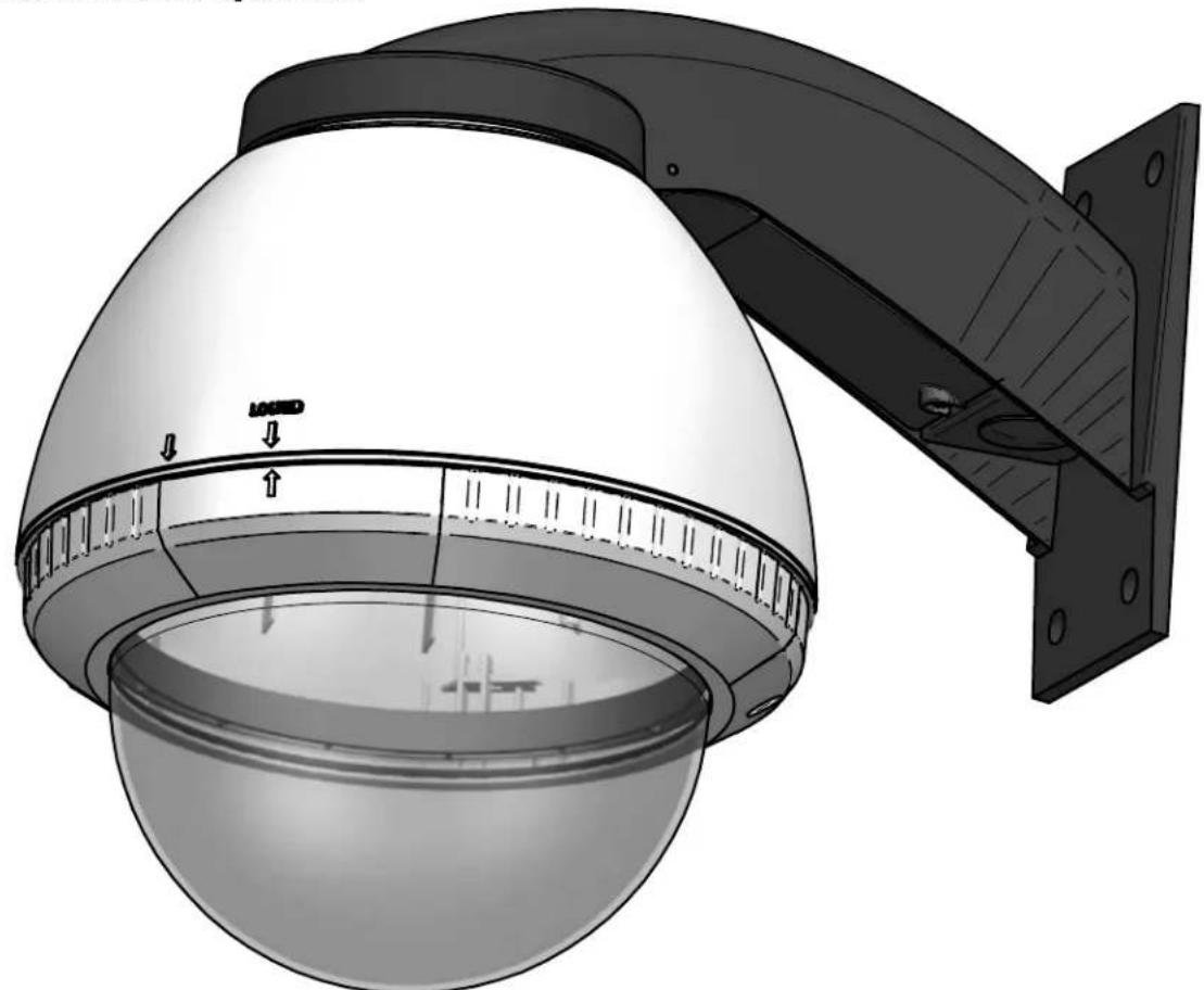
Technical illustration of a security camera with a dome and mounted panel (no text or symbols)FDW7C12N-3
Outdoor PTZ Fusion Dome Mount
www.videolarm.com
Installation and Operation Instructions for the following models:
FDW7C12N-3 IP Network Ready 7" Outdoor FusionDome PTZ Camera System with 23x zoom Day/Night camera, wall mount, MPEG-4/ MJPEG video compression, full D1. Clear dome, with 12VDC input, heater/blower
FDP7C12N-3 IP Network Ready 7" Outdoor FusionDome PTZ Camera System with 23x zoom Day/Night camera, pendent mount, MPEG-4/ MJPEG video compression, full D1. Clear dome, with 12VDC input, heater/blower
FDW7C12S-3 (Analog Version) 7" Outdoor FusionDome PTZ Camera System with 23x zoom Day/Night camera, wall mount, MPEG-4/ MJPEG video compression, full D1. Clear dome, with 12VDC input, heater/blower
FDP7C12S-3 (Analog Version) 7" Outdoor FusionDome PTZ Camera System with 23x zoom Day/Night camera, pendent mount, MPEG-4/ MJPEG video compression, full D1. Clear dome, with 12VDC input, heater/blower
Before attempting to connect or operate this product, please read these instructions completely. To be used with the 81-IN5409 Instruction Manual.

CERTIFIED
81-IN5423
01-09-2009
IMPORTANT SAFEGUARDS SAFETY PRECAUTIONS
1 Read these instructions.
2 Keep these instructions.
3 Heed all warnings
4 Follow all instructions.
5 Do not use this apparatus near water.
6 Clean only with damp cloth.
7 Do not block any of the ventilation openings. Install in accordance with the manufacturers instructions.
8 Cable Runs- All cable runs must be within permissible distance.
9 Mounting - This unit must be properly and securely mounted to a supporting structure capable of sustaining the weight of the unit.
Accordingly:
a. The installation should be made by a qualified installer.
b. The installation should be in compliance with local codes.
c. Care should be exercised to select suitable hardware to install the unit, taking into account both the composition of the mounting surface and the weight of the unit.
10 Do not install near any heat sources such as radiators, heat registers, stoves, or other apparatus (including amplifiers) that produce heat.
11 Do not defeat the safety purpose of the polarized or grounding-type plug. A polarized plug has two blades with one wider than the other. A grounding type plug has two blades and a third grounding prong. The wide blade or the third prong are provided for your safety. When the provided plug does not fit into your outlet, consult an electrician for replacement of the obsolete outlet.
12 Protect the power cord from being walked on or pinched particularly at plugs, convenience receplacles, and the point where they exit from the apparatus.
13 Only use attachment/ accessories specified by the manufacturer.
14 Use only with a cart, stand, tripod, bracket, or table specified by the manufacturer, or sold with the apparatus. When a cart is used, use caution when moving the cart/ apparatus combination to avoid injury from tip-over.
15 Unplug this apparatus during lighting storms or when unused for long periods of time.
16 Refer all servicing to qualified service personnel. Servicing is required when the apparatus has been damaged in any way, such as power-supply cord or plug is damaged, liquid has been spilled of objects have fallen into the apparatus, the apparatus has been exposed to rain or moisture, does not operate normally, or has been dropped.
Be sure to periodically examine the unit and the supporting structure to make sure that the integrity of the installation is intact. Failure to comply with the foregoing could result in the unit separating from the support structure and falling, with resultant damages or injury to anyone or anything struck by the falling unit.
UNPACKING
Unpack carefully. Electronic components can be damaged if improperly handled or dropped. If an item appears to have been damaged in shipment, replace it properly in its carton and notify the shipper.
Be sure to save:
1 The shipping carton and packaging material. They are the safest material in which to make future shipments of the equipment.
2 These Installation and Operating Instructions.
SERVICE
If technical support or service is needed, contact us at the following number:
TECHNICAL SUPPORT
AVAILABLE 24 HOURS
1-800-554-1124

text_image
CAUTION RISK OF ELECTRIC SHOCK DO NOT OPEN CAUTION: TO REDUCE THE RISK OF ELECTRIC SHOCK, DO NOT REMOVE COVER ( OR BACK). NO USER- SERVICE- ABLE PARTS INSIDE. REFER SEVICING TO QUALIFIED SERVICE PERSONNEL.
The lightning flash with an arrowhead symbol, within an equilateral triangle, is intended to alert the user to the presence of non-insulated "dangerous voltage" within the product's enclosure that may be of sufficient magnitude to constitute a risk to persons.
The exclamation point within an equilateral triangle is intended to alert the user to presence of important operating and maintenance (servicing) instructions in the literature accompanying the appliance.
During the labor warranty period, to repair the Product, Purchaser will either return the defective product, freight prepaid, or deliver it to Videolarm Inc. Decatur GA. The Product to be repaired is to be returned in either its original carton or a similar package affording an equal degree of protection with a RMA # (Return Materials Authorization number) displayed on the outer box or packing slip. To obtain a RMA# you must contact our Technical Support Team at 800.554.1124, extension 101. Videolarm will return the repaired Product freight prepaid to Purchaser. Videolarm is not obligated to provide Purchaser with a substitute unit during the warranty period or at any time. After the applicable warranty period, Purchaser must pay all labor and/or parts charges.
The limited warranty stated in these product instructions is subject to all of the following terms and conditions:
TERMS AND CONDITIONS
-
NOTIFICATION OF CLAIMS: WARRANTY SERVICE: If Purchaser believes that the Product is defective in material or workmanship, then written notice with an explanation of the claim shall be given promptly by Purchaser to Videolarm but all claims for warranty service must be made within the warranty period. If after investigation Videolarm determines that the reported problem was not covered by the warranty, Purchaser shall pay Videolarm for the cost of investigating the problem at its then prevailing per incident billable rate. No repair or replacement of any Product or part thereof shall extend the warranty period as to the entire Product. The specific warranty on the repaired part only shall be in effect for a period of ninety (90) days following the repair or replacement of that part or the remaining period of the Product parts warranty, whichever is greater.
-
EXCLUSIVE REMEDY: ACCEPTANCE: Purchaser's exclusive remedy and Videolarm's sole obligation is to supply (or pay for) all labor necessary to repair any Product found to be defective within the warranty period and to supply, at no extra charge, new or rebuilt replacements for defective parts.
-
EXCEPTIONS TO LIMITED WARRANTY: Videolarm shall have no liability or obligation to Purchaser with respect to any Product requiring service during the warranty period which is subjected to any of the following: abuse, improper use: negligence, accident, lightning damage or other acts of God (i.e., hurricanes, earthquakes), modification, failure of the end-user to follow the directions outlined in the product instructions, failure of the end-user to follow the maintenance procedures recommended by the International Security Industry Organization, written in product instructions, or recommended in the service manual for the Product. Furthermore, Videolarm shall have no liability where a schedule is specified for regular replacement or maintenance or cleaning of certain parts (based on usage) and the end-user has failed to follow such schedule; attempted repair by non-qualified personnel; operation of the Product outside of the published environmental and electrical parameters, or if such Product's original identification (trademark, serial number) markings have been defaced, altered, or removed. Videolarm excludes from warranty coverage Products sold AS IS and/or WITH ALL FAULTS and excludes used Products which have not been sold by Videolarm to the Purchaser. All software and accompanying documentation furnished with, or as part of the Product is furnished "AS IS" (i.e., without any warranty of any kind), except where expressly provided otherwise in any documentation or license agreement furnished with the Product.
-
PROOF OF PURCHASE: The Purchaser's dated bill of sale must be retained as evidence of the date of purchase and to establish warranty eligibility.
DISCLAIMEROF WARRANTY
EXCEPT FOR THE FOREGOING WARRANTIES, VIDEOLARM HEREBY DISCLAIMS AND EXCLUDES ALL OTHER WARRANTIES, EXPRESS OR IMPLIED, INCLUDING, BUT NOT LIMITED TO ANY AND/OR ALL IMPLIED WARRANTIES OF MERCHANTABILITY, FITNESS FOR A PARTICULAR PURPOSE AND/OR ANY WARRANTY WITH REGARD TO ANY CLAIM OF INFRINGEMENT THAT MAY BE PROVIDED IN SECTION 2-312(3) OF THE UNIFORM COMMERCIAL CODE AND/OR IN ANY OTHER COMPARABLE STATE STATUTE. VIDEOLARM HEREBY DISCLAIMS ANY REPRESENTATIONS OR WARRANTY THAT THE PRODUCT IS COMPATIBLE WITH ANY COMBINATION OF NON-VIDEOLARM PRODUCTS OR NON-VIDEOLARM RECOMMENDED PRODUCTS PURCHASER CHOOSES TO CONNECT TO PRODUCT.
LIMITATION OF LIABILITY
THE LIABILITY OF VIDEOLARM, IF ANY, AND PURCHASER'S SOLE AND EXCLUSIVE REMEDY FOR DAMAGES FOR ANY CLAIM OF ANY KIND WHATSOEVER, REGARDLESS OF THE LEGAL THEORY AND WHETHER ARISING INTORT OR CONTRACT, SHALL NOT BE GREATER THAN THE ACTUAL PURCHASE PRICE OF THE PRODUCT WITH RESPECT TO WHICH SUCH CLAIM IS MADE. IN NO EVENT SHALL VIDEOLARM BE LIABLE TO PURCHASER FOR ANY SPECIAL, INDIRECT, INCIDENTAL, OR CONSEQUENTIAL DAMAGES OF ANY KIND INCLUDING, BUT NOT LIMITED TO, COMPENSATION, REIMBURSEMENT OR DAMAGES ON ACCOUNT OF THE LOSS OF PRESENT OR PROSPECTIVE PROFITS OR FOR ANY OTHER REASON WHATSOEVER.

Electrical Specifications
FDW7C12N-3
FDW7C12S-3
FDP7C12N-3
Power 12VDC
Class 2 Only
FDP7C12S-3

50 WATTS
Accessories: Heater: 20 Watts, Blower: 2 Watt
Camera Power: (See Camera Specifications): 28 Watts Max
Tools Required: .100" Flat Head Screwdriver
English
Phillips Head Screwdriver

text_image
***Wall Mount Included with the following models: FFW7CN 9*** Wall Mount Included with the following models: FDW7CN-9, FDW7SN-9
*** Pan Tilt boxed separately along with its instructions.
1
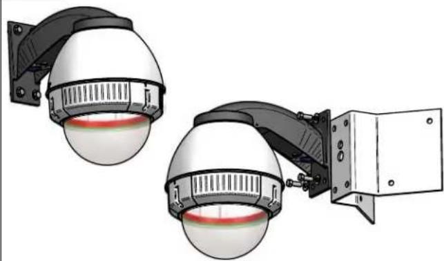
WALL MOUNTING
natural_image
Illustration of two security cameras mounted on a wall-mounted device, showing sensor lights and wiring (no text or symbols present)Securely mount unit to wall or to appropriate adapter bracket.
natural_image
3D rendering of a security camera with dome and mounted sensor array (no text or symbols visible)If using conduit connect, connect to incoming conduit fitting.
- Si usa el conducto conecte, conecte con la guarnición entrante del conducto.
- Si à l'aide du conduit reliez, reliez à l'ajustage de précision entrant de conduit.
- Wenn Sie Rohr verwenden, schließen Sie an, schließen Sie an ankommende Rohrbefestigung an.
- Se usando a canalização conecte, conecte ao encaixe entrante da canalização.
- Se per mezzo del condotto colleghi, colleghi al montaggio ricevuto del condotto.
3
natural_image
Illustration of a security camera with a dome and sensor array (no text or symbols)Open access door to access power and control connectors.
- Abra la puerta de acceso en los conectadores de la energía y de control del acceso.
- Ouvrez la porte d'accès aux connecteurs de puissance et de commande d'accès.
- Öffnen Sie Zugang zur Zugang Energie und zu den Geräteanschlüssen.
- Abra a porta de acesso aos conectores do poder e de controle do acesso.
- Apra il portello di accesso ai connettori di alimentazione e di controllo di accesso.
4
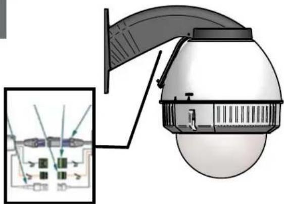
text_image
Diagram of a security camera with labeled components and an inset showing internal wiring connectionsMake wire connection as they are required for your needs.
- Haga la conexión del alambre como se requieren para sus necesidades.
- Établissez le rapport de fil comme ils sont exigés pour vos besoins.
- Stellen Sie Leitung Beziehung her, wie sie für Ihre Notwendigkeiten angefordert werden.
- Faça a conexão do fio como são requeridos para suas necessidades.
- Faccia il collegamento del legare come sono richiesti per i vostri bisogni.
5
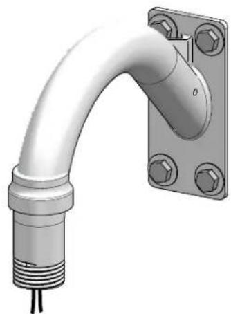
natural_image
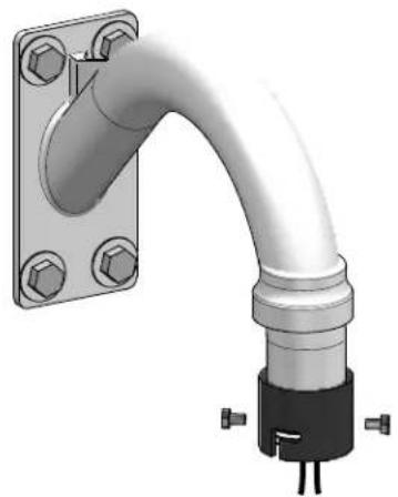
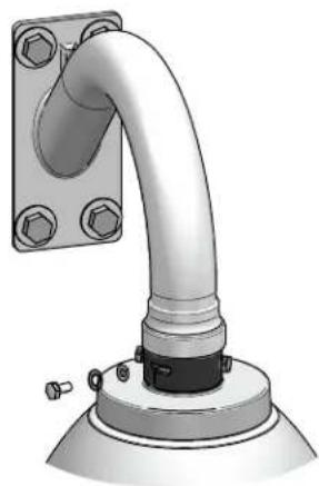
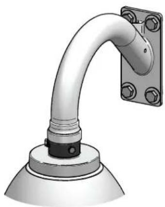
3D rendering of a metallic pipe fitting with mounting flange (no text or symbols)FOR PENDENT/ WALL MOUNTING
Securely mount bracket to wall. Pull wiring through bracket and position grommet as shown.
- Con seguridad soporte del montaje a emparedar. Tire del cableado a través del soporte y del ojal de la posición según lo demostrado.
- Solidement parenthèse de bâti à murer. Tirez le câblage par la parenthèse et le canon isolant de position comme montré.
- Sicher Einfassung Haltewinkel wall. Ziehen Sie Verdraftung durch Haltewinkel und Position Gummimuffe, wie gezeigt.
- Firmemente suporte da montagem a wall. Puxe a fiação através do suporte e do ilhó da posição como mostrado.
- Saldamente staffa del supporto da wall. Tiri i collegamenti tramite la staffa ed il gommino di protezione di posizione come indicato.
6
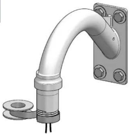
natural_image
3D rendering of a pipe fitting with mounting flange and bolted joints (no text or symbols)Wrap Teflon tape around the pipe threads to ensure a tight seal.
- La cinta del Teflon del abrigo alrededor de la pipa rosca para asegurar un sello apretado.
- La bande de teflon d'enveloppe autour de la pipe filète pour assurer un joint serré.
- Verpackung Teflonklebeband um das Rohr verlegt, um eine feste Dichtung sicherzustellen.
- A fita adesiva do Teflon do envoltório em torno da tubulação enfia para assegurar um selo apertado.
- Il nastro del Teflon dell'involucro intorno al tubo filetta per accertare una guarnizione stretta.
3
natural_image
3D rendering of a pipe fitting with a bracket and mounting flange (no text or symbols)Screw the coupling onto the pipe threads until it is hand tight.
- Atornille el acoplador sobre los hilos de rosca de la pipa hasta que es mano firmemente.
- Vissez le couplage sur les fils de pipe jusqu'à ce que ce soit main fortement.
- Schrauben Sie die Koppelung auf die Rohrgewinde, bis es Hand fest ist.
- Parafuse o acoplamento nas linhas da tubulação até que esteja mão firmemente.
- Avviti l'accoppiamento sui filetti del tubo fino a che non sia fortemente mano.
8
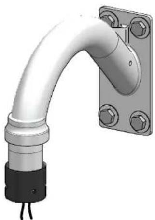
natural_image
3D rendering of a pipe fitting with mounting flange and terminal connectors (no text or symbols)Screw the (2) bolts into the coupling.
- Atornille (2) los pernos en el acoplador.
- Vissez (2) les boulons dans l'accouplement.
- Schrauben Sie die (2) Schraubbolzen in die Koppelung.
- Parafuse (2) os parafusos no acoplamento.
• Avviti (2) i bulloni nell'accoppiamento.
9
natural_image
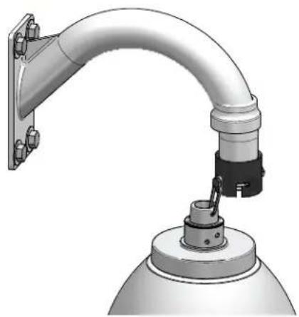
3D rendering of a mechanical pipe assembly with mounting bracket and base mount (no text or symbols visible)Loop the lanyard over the set screw to temporarily hold housing.
- Coloque el acollador sobre el tornillo de presión para celebrar temporalmente la cubierta.
- Faites une boucle la lanière au-dessus de la vis de réglage pour tenir temporairement le logement.
- Schlingen Sie die Abzuglinie über der Klemmschraube, um Gehäuse vorübergehend zu halten.
- Dê laços no colhedor sobre o parafuso de fixação para prender temporariamente a carcaça.
- Colleghi la cordicella in circuito sopra la vite di arresto temporaneamente per tenere l'alloggiamento.
10
natural_image
Technical diagram of a mechanical assembly with labeled components (no readable text or symbols)Make the appropriate wiring connections from the dome to the gooseneck.
- Haga las conexiones apropiadas del cableado de la bóveda al gooseneck.
- Établissez les rapports appropriés de câblage à partir du dôme au col de cygne.
- Stellen Sie die passenden Verdrahtung Beziehungen von der Haube zum gooseneck her.
- Faça as conexões apropriadas da fiação da abóbada ao gooseneck.
- Faccia i collegamenti adatti dei collegamenti dalla cupola al gooseneck.
11
natural_image
3D rendering of a pipe fitting with mounting flange and base (no text or symbols)Undo the lanyard, pull housing up and twist secure with the locking bolt and washers.
- Deshaga el acollador, tire de contener para arriba y fuerza seguro con el perno y las arandelas de fijación.
- Défaites la lanière, tirez lager vers le haut et tordez bloqué avec le boulon et les rondelles de fermeture.
- Annulieren Sie die Abzuglinie, ziehen Sie oben unterbringen und verdrehen Sie sicheres mit dem verriegelnschraubbolzen und den Unterlegscheiben.
- Undo o colhedor, puxe abrigar acima e torça seguro com o parafuso e as arruelas travando.
- Undo la cordicella, firi l'alloggio in su e torca sicuro con il bullone e le rondelle di bloccaggio.
12
natural_image
3D rendering of a pipe fitting mounted on a base with a mounting bracket (no text or symbols visible)Slide the grommet down over the coupling to prevent water from entering and complete the assembly.
- Resbale el ojal abajo sobre el acoplador para evitar que el agua entre y para terminar a la asamblea.
- Glissez le canon isolant vers le bas au-dessus de l'accouplement pour empêcher l'eau d'entrer et pour accomplir l'assemblée.
- Schieben Sie die Gummimuffe unten über der Koppelung, um zu verhindern, daß Wasser und die Versammlung durchzuführen hereinkommt.
- Deslize o ilhó para baixo sobre o acoplamento para impedir que a água entre e para terminar o conjunto.
- Faccia scorrere il gommino di protezione giù sopra l'accoppiamento per impedire l'acqua entrare e per completare il complessivo.
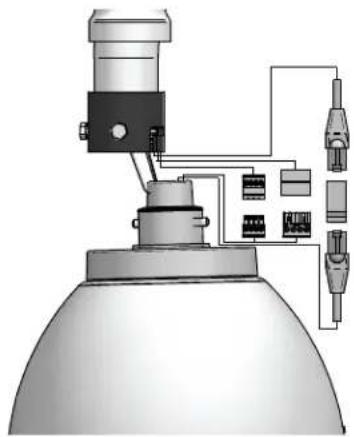
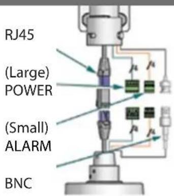
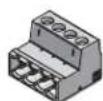
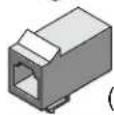
13 Power and Control Inputs (Outside of Housing)
text_image
RJ45 (Large) POWER (Small) ALARM BNCPOWER
| 1 | Camera Power (+ 12 VDC) Red | |
| 2 | Camera Power (- 12 VDC) Orange | |
| 3 | Accessory Power (+12 VDC) Yellow | |
| 4 | Accessory Power (-12 VDC) Green |
CONTROL RJ45 Ethernet Connector
ALARMS
| 1 Alarm 1 Blue | |
| 2 Alarm 2 Violet | |
| 3 Alarm 3 Gray | |
| 4 Common White |
Make the appropriate male and female connections. Indoor model does not include pre-run cables.
- Haga las conexiones masculinas y femeninas apropiadas. El modelo de interior no incluye pre-funciona los cables.
- Établissez les rapports masculins et femelles appropriés. Le modèle d'intérieur n'inclut pas pré-courent des câbles.
- Stellen Sie die passenden männlichen und weiblichen Beziehungen her. Innenmodell schließt nicht vor-laufen lassen Kabel ein.
- Faça as conexões masculinas e fêmeas apropriadas. O modelo indoor não inclui pre-funciona cabos.
- Faccia i collegamenti maschii e femminili adatti. Il modello dell'interno non include pre-fa funzionare i cavi.
Power and Control Inputs (Inside of Housing)
POWER
| 1 | Camera Power (+12 VDC) | Red |
| 2 | Camera Power (-12 VDC) | Orange |
ALARMS
| 1 Alarm 1 Blue | |
| 2 Alarm 2 Violet | |
| 3 Alarm 3 Gray | |
| 4 Common White |
Make the appropriate male and female connections. Indoor model does not include pre-run cables.
- Haga las conexiones masculinas y femeninas apropiadas. El modelo de interior no incluye pre-funciona los cables.
- Établissez les rapports masculins et femelles appropriés. Le modèle d'intérieur n'inclut pas pré-courent des câbles.
- Stellen Sie die passenden männlichen und weiblichen Beziehungen her. Innenmodell schließt nicht vor-laufen lassen Kabel ein.
- Faça as conexões masculinas e fêmeas apropriadas. O modelo indoor não inclui pre-funciona cabos.
- Faccia i collegamenti maschii e femminili adatti. Il modello dell'interno non include pre-fa funzionare i cavi.
14
Wire Gauge
| Total vA consumed | ,5 | ,75 | 1,0 | 1,5 | 2,5 | 4 | 6 | MM^2 AWG |
| 22 | 20 | 18 | 16 | 14 | 12 | 10 | ||
| 5.5 | ft/m | 400/121 | 600/182 | 960/292 | - | - | - | |
| 10 | 120/36.5 | 180/54.9 | 300/91.4 | 480/146 | 800/243 | 1390/396 | - | |
| 20 | 89/27.1 | 141/43.0 | 225/68.6 | 358/109 | 571/174 | 905/275 | 1440/438 | |
| 30 | 65/19.8 | 90/27.4 | 130/39.6 | 225/58.6 | 350/106 | 525/160 | 830/252 | |
| 40 | 44/13.4 | 70/21.3 | 112/34.1 | 179/54.6 | 285/86.9 | 452/138 | 720/219 | |
| 50 | 35/10.6 | 56/17.1 | 90/27.4 | 143/43.6 | 228/69.5 | 362/110 | 576/175 | |
| 60 | 29/9.4 | 47/14.3 | 75/22.9 | 119/36.2 | 190/57.9 | 301/91.7 | 480/146 | |
| 70 | 25/8.8 | 40/12.2 | 64/19.5 | 102/31.1 | 163/49.7 | 258/78.6 | 411/125 | |
| 80 | 31/7.6 | 34/10.3 | 55/16.8 | 85/25.9 | 140/42.7 | 215/65.5 | 340/103 |
These are recommended maximum distances for 12VDC with a 10% voltage drop.
- Éstos se recomiendan las distancias máximas para 12VDC con una gota del voltage del 10%.
- Ceux-ci sont recommandés des distances maximum pour 12VDC avec une chute de tension de 10%.
- Diese werden maximale Abstände für 12VDC mit einem 10% Spannungsabfall empfohlen.
- Estes são recomendados distâncias máximas para 12VDC com uma queda de tensão de 10%.
- Questi sono suggeriti distanze massime per 12VDC con una differenza de potenziale di 10%.
15
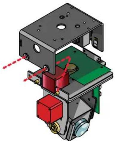
natural_image
3D mechanical assembly diagram showing internal components with red and green parts, no visible text or symbolsRemove Pan/Tilt from shipping carton. Install in base bracket in housing.
- Quite Pan/Tilt del cartón del envío. Instale en soporte bajo en la cubierta.
- Enlevez Pan/Tilt du carton d'expédition. Installez dans la parenthèse basse dans le logement.
- Entfernen Sie Pan/Tilt vom Verschiffenkarton. Bringen Sie in niedrigen Haltewinkel im Gehäuse an.
- Remova Pan/Tilt da caixa do transporte. Instale no suporte baixo na carcaça.
- Rimuova Pan/Tilt dalla scatola di trasporto. Installi in staffa bassa in alloggiamento.
16
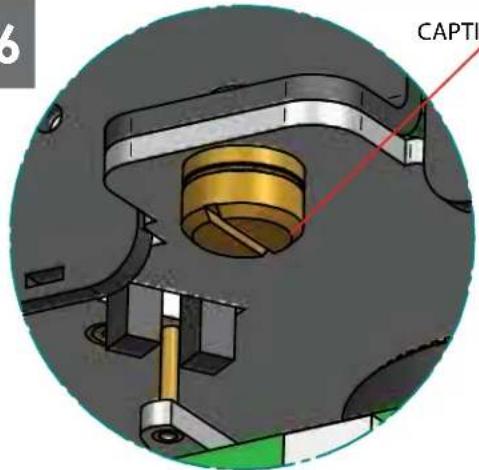
CAPTIVE SCREW
text_image
6 CAPTITo secure in place, tighten captive screw.
- Para asegurar en lugar, apriete el tornillo prisionero.
• Pour fixer en place, serrez la vis captive. - Um im Platz zu sichern, ziehen Sie Sicherheitsschraube fest.
- Para fixar-se no lugar, aperte o parafuso prisioneiro.
- Per fissare sul posto, stringa la vite prigioniera.
171
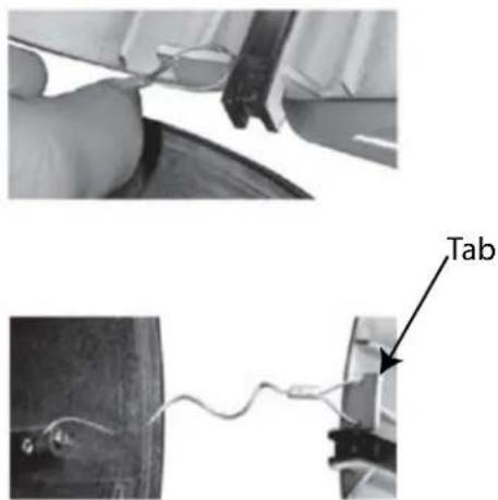
text_image
TabLoop the lanyard around the tab inside the housing.
- Coloque el acollador alrededor de la lengüeta dentro de la cubierta.
- Faites une boucle la lanière autour de l'étiquette à l'intérieur du logement.
- Schlingen Sie die Abzuglinie um den Vorsprung innerhalb des Gehäuses.
- Dê laços no colhedor em torno da aba dentro da carcaça.
- Colleghi la cordicella in circuito intorno alla linguetta all'interno dell'alloggiamento.
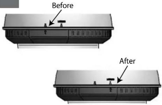
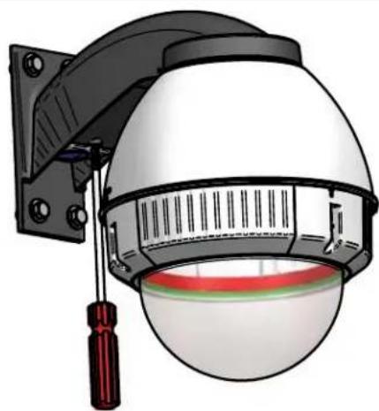
text_image
Before AfterAlign the arrows on the outside of the dome and lock.
natural_image
3D rendering of a mechanical component with a cylindrical rod inserted into a dome-shaped housing (no text or symbols visible)Fasten down the dome with a Phillips screwdriver.
- Sujete abajo de la bóveda con un destornillador Phillips.
- Attachez en bas du dôme avec un tournevis Phillips.
- Befestigen Sie sich hinunter die Haube mit einem Kreuzkopfschraubenzieher.
- Prenda abaixo a abóbada com uma chave de fenda Phillips.
- Fissisi giù la cupola con un cacciavite "phillips".
20
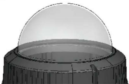
natural_image
3D rendering of a dome-shaped object with a central rectangular base and textured outer layer (no text or symbols)Wipe the dome clean.
- Limpie la bóveda limpia.
- Essuyez le dôme.
- Wischen Sie die Haube sauber ab.
- Limpe a abóbada limpa.
- Asciughi la cupola.
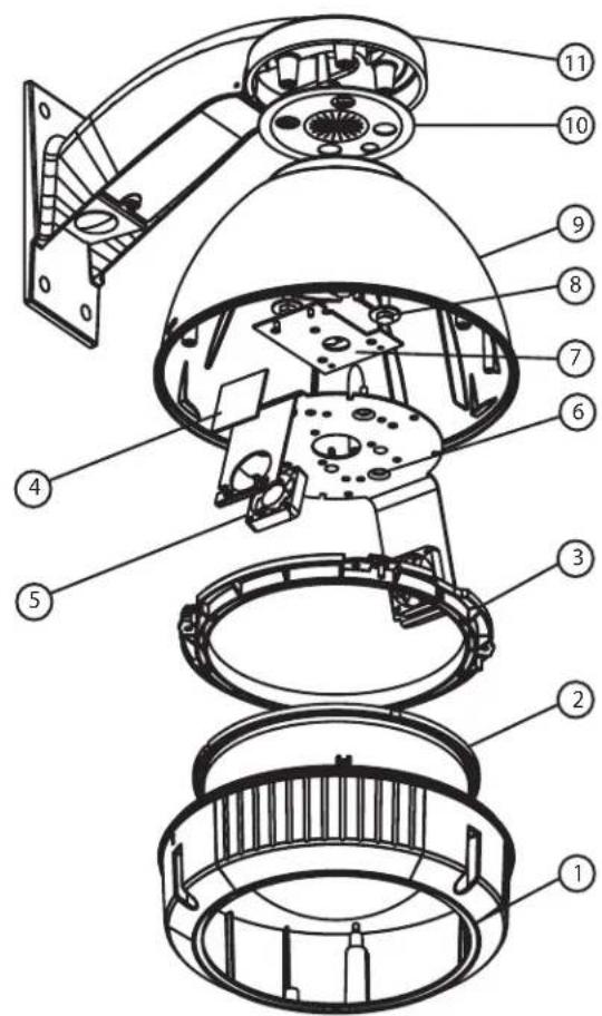
Replacement Parts List
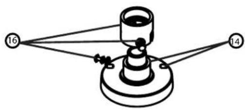
natural_image
Diagram of a mechanical or electrical component with labeled points 14 and 16, connected by lines to a central cylindrical component (no text or symbols beyond labels)FDW7C12N-3
FDP7C12N-3
FDW7C12S-3
FDP7C12S-3
text_image
Exploded view diagram of a smart home control device with numbered parts for identification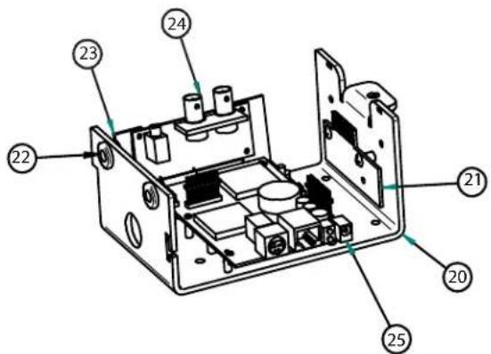
text_image
Technical diagram of an electronic device casing with numbered components for identification17

(1)
(1)
(2)
Part Number Description
| 1 RF FD7501 LOWER TRIM RING | |
| 2 FD /T TINTED REPLACEMENT CAPSULE | |
| FD7C CLEAR REPLACEMENT CAPSULE | |
| 3 RF FD703 DOME CLAMPING BRACKET | |
| 4 RF FD07/12 12 VDC HEATER | |
| 5 RF FD080 (12 VDC) BLOWER (USED IN 24V HOUSINGS) | |
| 6 RF FD060 CAMERA BRACKET | |
| 7 RF 40PCCM0D01 (12 VDC MODELS) | |
| 8 RF FD040 HOUSING HARDWARE | |
| 9 RF FD709 HOUSING TOP | |
| 10 RPFD2612 HOUSING TOP - GASKET | |
| 11 WM10 WM10 WALL MOUNT | |
| 14 SD0170 PENDANT HOUSING COUPLING | |
| 15 SD0180 QUICK RELEASE PIPE COUPLING | |
| 16 SD0160 PENDANT MOUNT BRACKET | |
| 17 RPPKE1100 HOUSING HARDWARE PACKET B | |
| 18 | RPPKH2090 ELECTRICAL PACKET |
| 19 | RPPKH2071 HOUSING HARDWARE PACKET A |
| N/S RPPKE1125 ELECTRICAL PACKET HB, FIXED NETWORK | |
| N/S RPTRN02 40VA WALL TRANSFORMER | |
| 20 RPVL2857 | PAN TILT BASE BRACKET |
| 21 RP76VL385A | PAN TILT CONNECTION PCB |
| 22 | RP96PSGK08 |
| 23 | RPVL3097 |
| 24 RP76P0F060E | IP CONNECTION PCB |
| 25 RP7OP14015 | IP CARD |
Product Registration/Warranty
Thank you for choosing Videolarm. We value your patronage and are solely committed to providing you with only the highest quality products available with unmatched customer service levels that are second-to-none in the security industry.
Should a problem arise, rest assure that Videolarm stands behind its products by offering some of the most impressive warranty plans available: 3 Years on all Housings, Poles, Power Supplies, and Accessories and 5 Years on all camera systems (SView, QView, Warriors), and InfraRed Illuminators.

Register Your Products
5
Option 1: Online Option 2: Mail-In
Take a few moments and validate your purchase with our Online Product Registration Form at www.videolarm.com/productregistration.jsp
or complete and mail-in the bottom portion of this flyer.
Register your recent Videolarm purchases and benefit from the following:
Simple and Trouble-Free RMA process•
Added into customer database to receive product updates / news•
Eliminate the need to archive original purchase documents: •
Receipts, Purchase Orders, etc...

Cut at the dotted Line
Place in envelope, affix stamp and mail to: Videolarm ATTN: Warranty
2525 Park Central Ave.
Decatur, GA 30035
Main Contact Info
First Name: ____ Last Name: ____
Professional Title: Company:
Address 1: ____ Address 2: ____
City: State / Province/Country:
Zip / Postal Code: ____ Phone Number:
E-mail Address:
Product Information
Please Circle One: Business Personal
Name & Location of Company / Store where Purchased:
(City, State, Country)
Videolarm Product ID ____ Product Description ____
Serial #
(Available only for Camera Systems, IR Illuminators, Wireless Devices)
PO#