
FCS-1151 - Security Camera LEVELONE - Free user manual and instructions
Find the device manual for free FCS-1151 LEVELONE in PDF.


| Product Type | IP Security Camera |
| Model | FCS-1151 |
| Brand | LevelOne |
| Image Sensor | 1/3" CMOS |
| Resolution | 2 Megapixels (1920x1080) |
| Video Compression | H.264, MJPEG |
| Network Interface | 10/100 Base-T Ethernet |
| Power Supply | PoE (802.3af) or 12V DC |
| Dimensions (WxHxD) | 7.2 cm x 5.8 cm x 12.5 cm |
| Weight | Approx. 500 g |
| Minimum Illumination | 0.1 lux |
| Lens Type | Fixed, 3.6 mm |
| Day/Night | Yes, with IR cut filter |
| Main Functions | Motion detection, event recording, PTZ control, remote viewing, audio support |
| Software Included | IP CamSecure Lite (free), Pro/Pro Plus (optional) |
| Operating Temperature | 0°C to 50°C |
| Storage Temperature | -20°C to 60°C |
| Protection Rating | IP66 (estimated) |
| Cleaning | Clean lens with soft, dry cloth. Use mild detergent if needed. |
| Safety Instructions | Use only supplied power adapter or PoE. Protect from moisture. |
| Spare Parts & Repairability | Contact LevelOne support for parts. No user-serviceable parts inside. |
Frequently Asked Questions - FCS-1151 LEVELONE
User questions about FCS-1151 LEVELONE
0 question about this device. Answer the ones you know or ask your own.
Ask a new question about this device
Download the instructions for your Security Camera in PDF format for free! Find your manual FCS-1151 - LEVELONE and take your electronic device back in hand. On this page are published all the documents necessary for the use of your device. FCS-1151 by LEVELONE.
USER MANUAL FCS-1151 LEVELONE
Copyright (c) 2010 Digital Data Communications Co., Ltd. All Rights Reserved.
All features and functions are subject to change without notice. Please visit www.level1.com for the latest ones.
Index
INSTALLATION....4
MINIMUM SYSTEM REQUIREMENT 4
INSTALLIP CAMERA(S) 4
INSTALL CAPTURE CARD(S) 4
IP CAM SECURE INSTALLATION....5
MAIN CONSOLE....6
PLAYBACK....11
TO WITHDRAW THE RECORD....14
SEARCH MODE....15
ENHANCEMENT 21
SAVE VIDEO / SAVE IMAGE 22
PRINT /BACKUP....23
LOG VIEWER....24
SCHEDULE....28
ENCODING OPTIONS PANEL 31
GUARD 34
EVENT 35
ACTION 51
CONFIGURATION ....53
MONITOR DISPLAY....66
SAVE/LOAD CONFIGURATION....67
COUNTING APPLICATION....68
LOG VIEWER....69
NETWORK SERVICE....78
LIVE STREAMING SERVER....78
REMOTE PLAYBACK SERVER....82
E-MAP 86
EDIT MODE....87
OPERATE MODE....88
LAYOUT ADJUSTMENT....89
LIVE VIEWER 91
DBTOOLS 96
BACKUP....100
APPENDIX A - 3GPP SERVICE....104
1.1 CONFIGURATION FROM LEVELONE SERVER 104
1.2 CONFIGURATION FROM 3G MOBILE PHONE....105
APPENDIX B – PDA / SMART PHONE CLIENT ....107
1.1 INSTALLPDA / SMART PHONE CLIENT....107
NOTE: IF YOU DO NOT HAVE MICROSOFT® ACTIVESYNC INSTALLED, A MESSAGE WILL APPEAR "CANNOT FIND ACTIVESYNC. PLEASE
REINSTALLACTIVESYNC AND THEN RUN THIS INSTALLATION AGAIN." 107
1.2 EXECUTE PDA / SMART PHONE CLIENT....107
APPENDIX C - I-PHONE BROWSER 111
Minimum System Requirement
| System Total FPS (@ CIF) | 64 channels | 32 channels | 16 channels | 8 channels | 4 channels |
| CPU Intel Core 2 Quad | Intel Core 2 Duo | Intel Pentium D 930 | Intel P4 2.8 GHz | Intel P4 2.8 GHz | |
| RAM 21 GB | 1 GB 1 GB | 512 MB 512 MB | |||
| Mother-board Intel 945 or 965 chip or above, Intel Chipset and ASUS recommended | |||||
| Display ATi Radeon 9200 , nVIDIA GeForce FX-5200 , Intel 945G/965G or above (ATi recommended) | |||||
| Ethernet 100 baseT or above, Gigabit LAN recommended | |||||
| Hard Disk 80 GB or above | |||||
| OS | MS Windows 2000 / XP pro sp2 / 2003 / VISTA/Win7 | ||||
Install IP camera(s)
Step 1: Set up the IP camera referring to the quick installation guide provided.
Step 2: Check the network between the IP camera and the system.
Step 3: Add the IP camera to the system. See details on later pages.
Install capture card(s)
Step1: Insert the card onto an empty PCI slot. Connect the Audio/Video Cable to the connector in the same color.
Step 2: Turn on your PC and start Windows.
Step 3: Insert the included Software CD into CD-ROM.
Step 4: Run SetupDrv.exe from the CD-ROM driver/ directory to install the Capture Card driver.
Step 5: Run dxdiag.exe from start menu 'Start->Run' to check your DirectX version. If the installed version is less than 9.0, install DirectX 9.0 from the CD-ROM directx9/ directory.
Step 6: After driver being installed, restart your PC.
Installation
IP CamSecure Installation
Run Setup.exe from the CD-ROM root directory and follow the onscreen instruction to complete installation.
Custom Setup Type:
You may install the system to the directory of your preference and choose which feature you want to install to the PC.
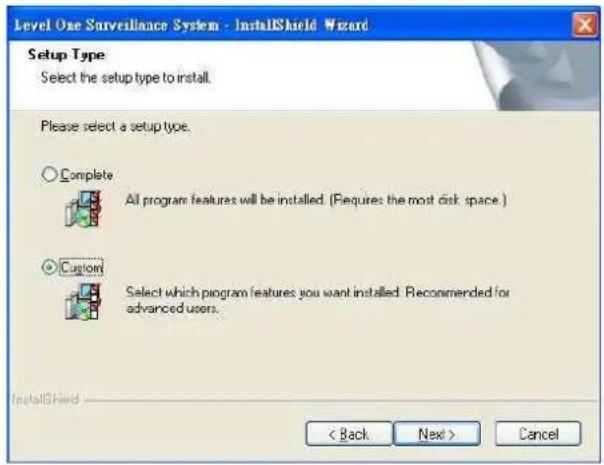
Hint: You may, for instance, install only Playback and/or LiveView on the PC at home or other remote site from which you do not install the camera but are going to watch them remotely.

**IP CamSecure Lite is free bundled with LevelOne IP camera and Capture Card.
** IP CamSecure professional version is available upon purchase. While using IP CamSecure Professional version, please use the SN or the included USB dongle into USB port as a license key.
Main Console
Main Console
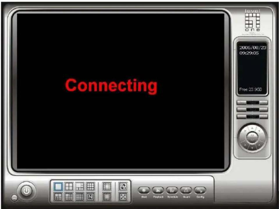
The main operation system. To activate schedule recording, setup smart guard and configure system setting.
Main Console

Exit: Shut down the main console or log out current user.
Minimize: Minimize the Main Console.
Screen Division: Allocate the sub-screen displays of cameras by clicking on the icon of desired layout. Quick switch to single camera display by double click the particular sub-screen. Double click the single camera display again to regain previous screen division layout.

Divide into 1 screen(s)

Divide into 4 screen(s)

Divide into 6 screen(s)

Divide into 9 screen(s)

Divide into 10 screen(s)

Divide into 13 screen(s)

Divide into 16 screen(s)

Divide into N screen(s)

Divide into 13 screen(s)

Divide into 17 screen(s)

Switch to Full screen

Rotate all screens
Main Console
On Screen Menu:

Right click on the camera screen and get the On Screen Menu from which you can Enable Move and Talk, and Connect / Disconnect the camera.
Enable Move: By selecting the enable move function, you may adjust the camera's view by clicking and dragging on the display screen. To cancel this function, right click on the screen and select Disable Move.
Note: You can only work on current camera after clicking enable move.
Enable Talk: With cameras that support audio function, you may select enable talk to utilize the function.
Connect/ Disconnect: Right click on the display screen and select Connect/ Disconnect to modify the connecting status of the camera.
Show Camera: Select the camera to be displayed from the Show Camera Menu.
Snapshot: Select the snapshot function to capture a specific video image immediately. You have the options to copy the image to the clipboard or to save it.
Manual Record: Start recording video by selecting manual record.
Toggle Full Screen: To view a specific channel with full screen.
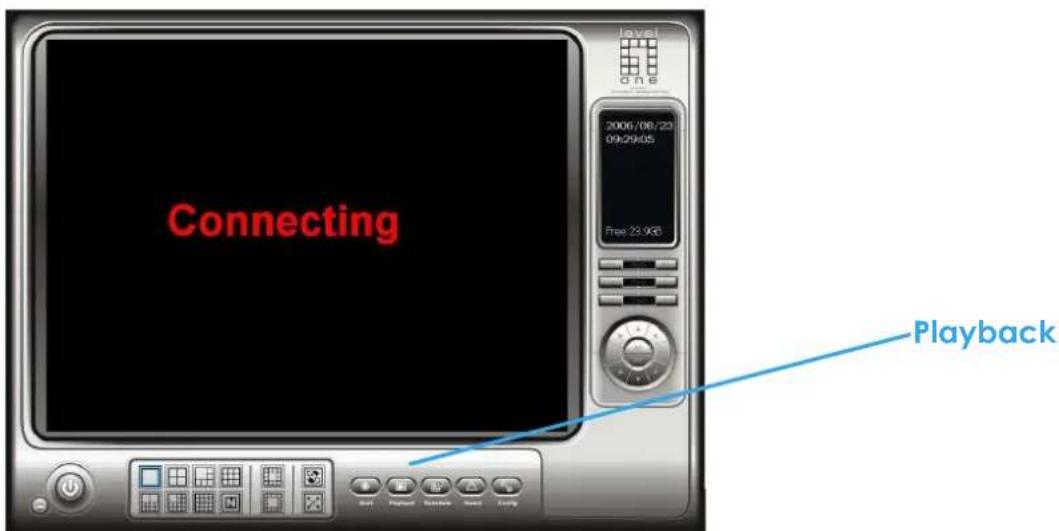
Playback: Click the icon to get Playback Console. You can watch recorded video, search, adjust image from records data, save video pictures and print images, check log in information, event records and setup recording function configuration. See Playback in detail on later pages.
Main Console
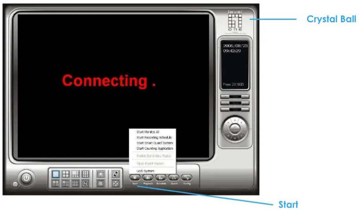
Start: Click on the pull down menu to Start/Stop Schedule System, Start/Stop Smart Guard System, Start/Stop Counting Application or click on Start/Stop Monitor All to activate/ deactivate all the functions above. Stop alarm by clicking Open Event Report. You can also cancel all events by click the Crystal Ball, see it in detail on later pages.
Note: The system will consider everything in the screen is normal when you click Start to activate monitor function. Therefore, for example, if you want to detect Missing Object, be sure the object that you want to protect is in its position when you click Start bottom.
Main Console

Schedule: Schedule recording time table and setup recorder configuration. See Schedule in detail on later pages.
Smart Guard: Add/edit type(s) of events which you want to detect; setup reaction(s) responding to events. See Guard in detail on later pages.
Config: Setting, Save/Load Configuration, Counting Application, Log Viewer and Backup.
PTZ Camera Control: Control the movement of installed PTZ camera.
Information Window: Shows the system information including date, time, free HD space and customized text. You can customize the setting of Information Window in Config > Setting > General.
Crystal Ball: Indicates the working status of the system. In blue color rolling when system is recording; in red when event detected. When the Crystal Ball is red, click it can you can cancel event(s).
Playback

Watch the recorded video, view and/or search for unusual events and recorded system information.
*There is only 1 channel displayed in Playback in IP CamSecure Lite while there are up to 16 channels displayed in IP CamSecure Pro/Pro Plus simultaneously.
Playback

Scroll Bar: Quick search on the video, drag it to where you want to review.
Exit: Turn off the Playback Console.
Minimize: Minimizes the playback Console window.
Control: Play, pause and stop the video.
Cue: Set up the Cue In and Cue out points of the clip you want to save as a video clip or a back up file with all the information recorded (including log info, events reported and so on). Cue In and Cue Out time will show on the Playback Information display once they are set.
Speed: Controls the play back speed, speed up and down.
Zoom: Zoom in and zoom out. You can get a close up view of the recorded video and move to the spot you want to view by dragging the screen.
Playback

Browse Mode: Play the recorded video.
Search Mode: Click on the Search Mode icon and get the Intelligent Search Tool panel. You can setup unusual events here to detect abnormality that occurred during the video was recorded. To setup unusual events, see this in detail on later pages.
SCREEN DIVISION: Allocate the sub-screen display by clicking on the desired layout icon. To switch to single camera display, double click on a particular sub-screen. Double click on the screen again to regain previous screen division layout.
INFORMATION DISPLAY WINDOW: Display video date and time, current video status, cue in/ out points' time, and speed.
Date Time: By clicking on Date Time bottom, you can withdraw the video record that you want to review. As you click on the Date Time bottom, a control panel will show up. Follow the instruction on the next page to withdraw the record.
Audio Volume Control: Adjust the sound level.
Playback
Day-Time Panel

To withdraw the record
Step 1: From the window at the top left of the Day-Time Panel, select the date you want to check, and you will see red/green lines show on the time table implying available recorded video.
Step 2: You can select the video clip you want to review by left-clicking and dragging to highlight the time period. Besides using the time-table, you may indicate the time period of video that you want to see by using the Start Time and End Time in Date Time Period section.
Step 3: In Select Camera(s) section, select the camera(s)/channel(s) from which you want to see the video. You can select all the cameras by clicking Select All bottom.
Step 4: Check the box of Enable Preview to get the preview of the video you select.
Step 5: Click OK when you are satisfied with the setting.
Playback
Search Mode
Unusual Event - General Motion
Intelligent Search Tool panel:
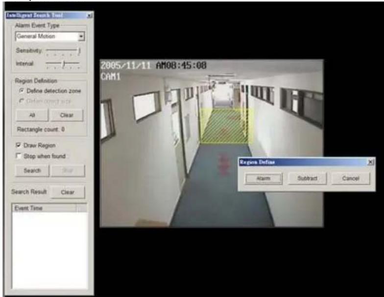
Click on the Search Mode icon and get the Intelligent Search Tool panel. You can setup unusual events here to detect abnormality that occurred during the video was recorded.
There are 5 types of unusual events:
General Motion
Foreign Object
Missing Object
Lose Focus
Camera Occlusion
*IP CamSecure Lite only has General Motion option in Search Mode.

General Motion: Detect any movement in the defined detection zone.
Define detection zone: To detect General Motion, you have to define a detection zone. Left-click and drag, and draw a detection zone. You may define more than one zone on the screen by repeat the process.
Playback
Unusual Event - General Motion
Sensitivity: Click and move the control bar to the right to increase sensitivity, that is, a relatively small movement will trigger the alarm. Move to the left to reduce the sensitivity of movement detection. Set up an appropriate Sensitivity value will reduce the chance of false alarm. For example, you can lower the Sensitivity to avoid the alarm being triggered by a swinging tree in the breeze.
Interval: Click and move the control bar to the right to increase interval time, so that the alarm will only be triggered when the movement lasts longer. Move to the left to reduce the interval time.

Stop when found: Check the box, and the video will stop at the point when a motion in the detection zone is detected. Otherwise, the video will keep rolling and all the events detected will show on the list in Search Result box. Click on the listed event date/time, you will jump to the point in the video where a motion is detected.
Click on the listed event date/time, you will jump to the point in the video where a motion is detected.
Playback
Unusual Event - Foreign Object
Intelligent Search Tool panel:
Click on the Search Mode icon and get the Intelligent Search Tool panel. You can setup unusual events here to detect abnormality that occurred during the video was recorded.
Foreign Object: Alarm is set off when an object appears in the defined area on the screen.


Define detection zone: To detect Foreign Object you have to define a detection zone. Left-click and drag, draw a detection zone. Alarm will be triggered when an object appears in the detection zone.
Define object size: Drag and draw a square on the screen to define the size of a foreign object.
Playback
Unusual Event - Foreign Object
Sensitivity: Click and move the control bar to the right to increase sensitivity, that is, a relatively small movement will trigger the alarm. Move to the left to reduce the sensitivity of movement detection.
Interval: Click and move the control bar to the right to increase interval time, so that the alarm will only be triggered when the object has been removed from the area for longer. Move to the left to reduce the interval time. Set up an appropriate Interval value will reduce the chance of false alarm. For example, you can lower the Interval to avoid the alarm being triggered by a pedestrian.
Playback
Unusual Event - Missing Object
Intelligent Search Tool panel:
Click on the Search Mode icon and get the Intelligent Search Tool panel. You can setup unusual events here to detect abnormality that occurred during the video was recorded.
Missing Object: Alarm is set off when the defined object is removed from the defined area on the screen.

Define detection zone: To detect Missing Object you have to define a detection zone. Left-click and drag, draw a detection zone. Alarm will be triggered when the defined object is removed from the detection zone.
Define object size: To tell the system how big the defined object is. Drag and draw a square on the screen, on the object that you want to protect.
Playback
Unusual Event - Missing Object / Lose Focus / Camera Occlusion
Sensitivity: Click and move the control bar to the right to increase sensitivity, that is, a relatively small movement will trigger the alarm. Move to the left to reduce the sensitivity of movement detection.
Interval: Click and move the control bar to the right to increase interval time, so that the alarm will only be triggered when the object has been removed from the area for longer. Move to the left to reduce the interval time.
Lose Focus: System will inform you when the camera(s) are losing focus.
Camera Occlusion: Alarms when any of the cameras is blocked.
Playback
Enhancement

General Setting: Check the circle and chose whether you want to apply the setting to all the channels or only to those currently show on the screen.
Filter Setting
Visibility: Check the box and adjust the gamma value of the image, which means, you may enhance the image and make it cleaner.
Sharpen: Check the box to activate the function. Move the control bar to the right to sharpen the image, to the left to soften it.
Brightness: Check the box to activate the function. Move the control bar to the right to make the image brighter.
Contrast: Check the box to activate the function. Move the control bar to the right to increase contrast.
Grey Scale: Check the box to show the record in grey scale mode, which is, in black and while.
Playback
Save Video / Save Image
Save Video
Step 1: Choose the camera display you want to save as a video clip.
Step 2: Set up the Cue In and Cue Out points, the cue in and cue out time will show up on the display.
Step 3: Click Save Video icon, choose the folder where you want to save the file, enter the file name and click SAVE. You may export (save) the record with both audio and video or you can explore the video only.
Step 4: Choose the compression format and then save the video.
Save Image
Step 1: Chose the camera display from which you want to save pictures.
Step 2: Click Save Image bottom and when the image you want is on the screen. You may click Pause to freeze the video, use Step Forward/ Step Backward function to find the picture you want to save.
Step 3: Choose the folder and the format of image (BMP or JPEG) you prefer and then click save.
Note: You may pre-set a folder and format that you want to save the images (see this in detail on later pages.), thus skip Step 3.
Playback
Print / Backup
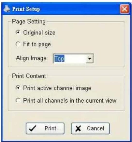
Page Setting: Print in original size or fit the page.
Align Image: Top, Center or Bottom
Print Content: Print the image from selected channel or all the channels shown on the screen
Backup: Different from Save Video, the Backup function saves everything from the Playback panel, including log information.
You can open the Backup file on any PC with Windows OS and have the full function Playback panel on it and take the backup file to elsewhere to work on the recorded video.
Playback
Log Viewer
*IP CamSecure Lite only has System Log option in Log Viewer.

Unusual Event: You can check out the history of Unusual Event that had been detected by Smart Guard System.
Step1: Choose the type of event you want to check or select "All" on the pull-down menu for all types of events.
Step 2: Choose from which camera you want to check the event(s) or select "All" for all the channels available.
Step 3: You can either view the events on a particular date or during a given time period. To search and view Unusual Event on a particular date, mark the box right after "Date" and indicate the date you want to check.
You may also point out two different time points and search for Unusual Event between them. Mark the box in the Date &Time column and then enter the date and time.
Step 4: Click Search
Note: When you are working with a video record,
-
Log Viewer will search Unusual Event in the video record by default, that is, to search in Date &Time mode, start from the beginning of the record and to the end of the record.
-
There will be a link icon right beside the event time; by clicking on the link icon you will jump to the point where the Unusual Event took place.
Playback
Log Viewer
Step 3
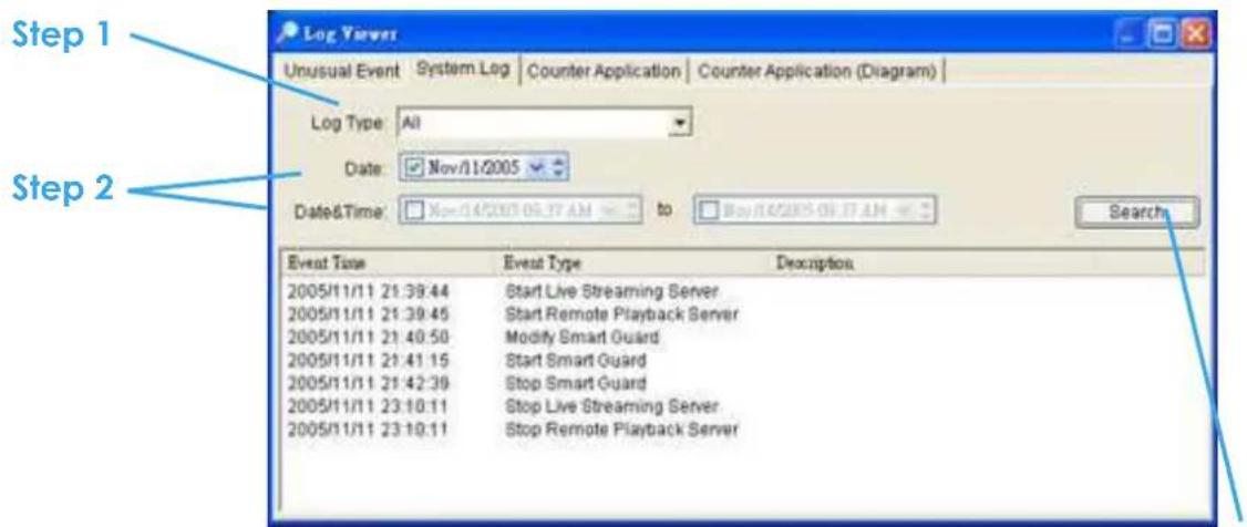
System Log: You can choose the Log Type form the pull-down menu, including: Console Startup, Console Shutdown, User Login, User Logout, Start Schedule, Stop Schedule, Execute Recycle, Execute Backup, Enable Channel, Disable Channel, Start Smart Guard.
Step1: Choose the type of event you want to check or select "All" on the pull-down menu for all types of events.
Step 2: You can either view the events on a particular date or during a given time period. To search and view Unusual Event on a particular date, check the box right after Date and indicate the date you want to check. You may also point out two different time points and search for Unusual Event between them. Mark the box in the Date &Time column and then enter the date and time.
Step 3: Click Search.
Playback
Log Viewer - Counting Application
Counting Application:
You can see the results of Counting Application during the time period you set.
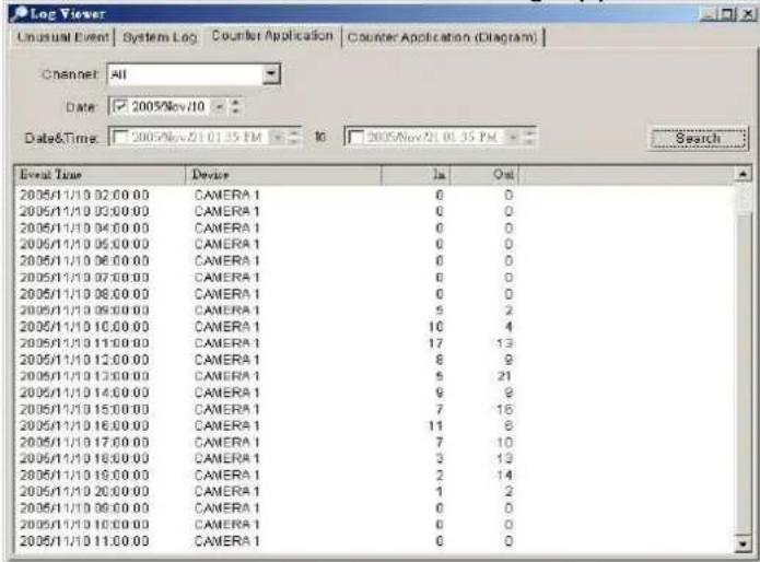
Counting Application (Diagram):
The Counting Application result data will show in a diagram.

Playback Setting
Database Source:
Choose from which location you are going to withdraw the record, from the PC you are working with or to get the access a database via the Internet. See Config > Remote Playback Server in detail on later pages.
Play:
Play when open: Check the box and set the system to play the video clip every time when you withdraw it from the database.
Next interval: Set the interval with which the video goes forward when you click Next icon on the control panel.
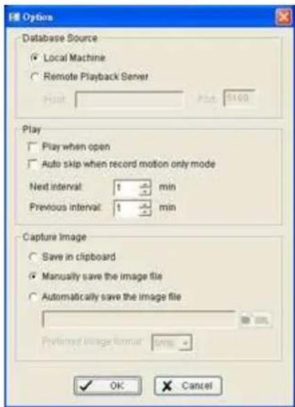
Previous interval: Set the interval with which the video goes backward when you click Previous icon on the control panel.
Capture Image: Setup how you want to save image.
Save in clipboard: The image will be saved in the clipboard and be able to paste on other application software.
Manually save the image file: You can manually choose where you want to save the image, name the saved file and which format you want to save the image.
Automatically save the image file: By giving the system a path/URL and the image format, it will automatically save the image accordingly every time you click Save Image bottom.
Schedule

Click on Schedule icon on Main Console and get the Schedule configuration panel to setup the time schedule for video recording.

Day Mode
Schedule the cameras on a daily basis, which means that the recorder will be on and off, at the same time every day, according to the same schedule you setup.
To setup the time schedule for each camera, you may
-
Load the preset Modes or
-
Insert a new schedule manually.
To load preset Modes
Click on the Load icon and get a pull-down menu.
Regular Mode: Record video 24 hours a day with the setting of 30 FPS (frames per second), Normal video quality and Normal resolution.
Office Mode: Record video from 8 am to 8 pm (08:00 – 20:00, shown as a red bar on Schedule Configuration panel) with 30 FPS, Normal video quality and Normal resolution.
Shop Mode: Record video from 10 am to 10 pm (10:00 – 22:00) with 30 FPS, Normal video quality and Normal resolution.
High Security Mode: Record video 24 hours a day with the setting of 30 FPS, Highest video quality and High resolution.
Disk Saving Mode: The system will start recording only when a motion on the screen is detected, 24 hours a day (shown as a green bar on Schedule Configuration panel), with the setting of 30 FPS, Normal quality and Normal resolution. You can adjust the sensitivity, interval and detection area of motion detection in schedule Configure
Minor Mode: The system will start recording only when a motion on the screen is detected, 24 hours a day (shown as a green bar on Schedule Configuration panel), with the setting of 15 FPS, Low quality and Low resolution. You can adjust the sensitivity, interval and detection area of motion detection in schedule Configure.
Adjust the scheduled setting: Although you have loaded the Modes by Load function, you can still manually make some changes of it.
Option 1: Move the cruiser to the Time Bar to change the length of it or move the bar sideway to change the start and stop points.
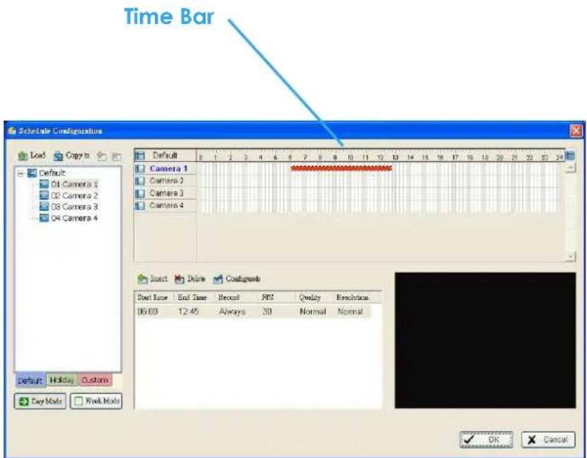
Option 2: Click the Configure icon or double click schedule information on the screen (highlighted in blue), to obtain the Encoding Options panel and change the setting as wished.
Note: The time schedule setting is based on 15 minutes.
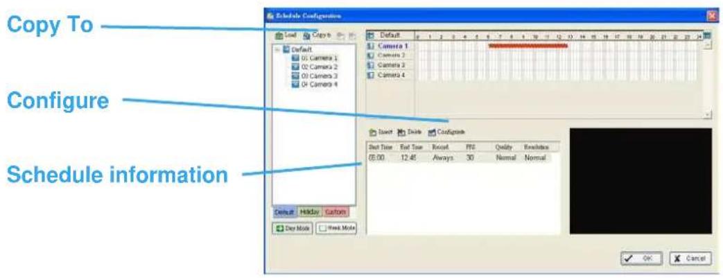
Copy To: You may set up the schedule for each channel/camera by repeating the process above, or simply apply the setting of a single camera to all the others.
Encoding Options Panel

Always Record: Select this option to record the video at all time.
Record on Event: Select this option to obtain the Select Event panel. From the Smart Guard/Digital Input list, check the box of the camera(s) that you want to trigger the recording action. Click OK to complete the setting.
*Smart Guard is only in IP CamSecure Pro/Pro Plus.
Record on Motion: Select this option to start recording when there are motions detected. You may adjust the sensitivity and the frame interval.
Pre-record/ Post-record Time: The pre-record/ post-record function saves the recording data accordingly. For instance, to set up a 5 second pre-record time means the system will start saving the recording data 5 seconds before the event happens.
To insert a new schedule manually
Step 1: Left-click and draw the length you want on time table. The scheduled time will show as a grey bar.
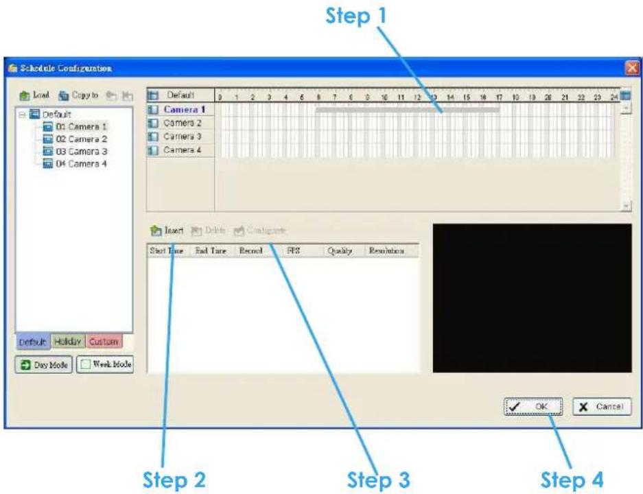
Step 2: Click on the Insert icon and add a new schedule with the setting of Regular Mode, that is, to record video during the time period you set with 30 FPS, Normal video quality and Normal resolution.
Step 3: Change the setting if you want, by click on the Configure icon or double click the schedule information.
Step 4: Click OK.

Week Mode: Schedule the cameras for each day of the week differently. Besides that, you may appoint extra holidays in Week Mode.
Default: Follow the same process to setup the schedule for every day in a week.
Holiday: You may appoint Holiday(s) on which the system will work as the setting of Sunday.
Custom: Or you can appoint a particular date(s) on which the system will work on a special schedule different from the others.
To insert a new schedule manually
You can also setup schedules manually in Week Mode by following the same process as in Day Mode.
Guard
*Guard is only in IP CamSecure Pro/Pro Plus.

Click on the Guard bottom on the Main Console and start Event and Action Configuration panel. You need to assign an event you want to detect and then set up an action with which the system will react when the assigned event is detected.
Crystal Ball: Indicates the working status of the system. In blue color rolling when system is recording; in red when event detected. When the Crystal Ball is red, click it can you can cancel event(s).

Event

There are three sources of events: Camera (video image), Digital input (device that connected to you PC) and System (condition of your hardware). You can assign multiple events by following the instruction below.
Assign a Camera event
Step 1: Choose a channel from cameras and click the Insert Event icon.

Step 2: There are 6 types of events, Signal Lost, General Motion, Foreign Object, Missing Object, Lose Focus and Camera Occlusion. Select the event you want on Event Type list and then click OK.
Step 3: Configure the setting of the Event Type. See the following instruction.
Event - Signal Lost

Basic
Enable Event: Check the box to activate.
Life Cycle
Automatic cancel event when event disappears: the alarm/action will be off once the abnormality is fixed or ends.
Manual cancel event or event last triggered: The alarm/action will continue until being cancel from the Main Console (Start>Open Event Report>Cancel All). Therefore, when the user is currently not at seat watching the screen he or she will be notified by the alarm.
Activated Period: You can set the system to react during certain time period; for example, office hours.
Event - General Motion
Detect any movement in the defined detection zone.
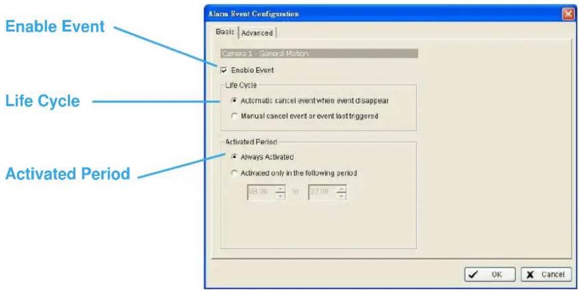
Basic Setting
Enable Event: Check the box to activate.
Life Cycle
Automatic cancel event when event disappears: the alarm/action will be off once the abnormality is fixed or ends.
Manual cancel event or event last triggered: The alarm/action will continue until being cancel from the Main Console (Start>Open Event Report>Cancel All). Therefore, when the user is currently not at seat watching the screen he or she will be notified by the alarm.
Activated Period: You can set the system to react during certain time period; for example, office hours.
Event - General Motion
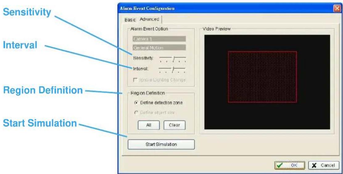
Advanced setting
Sensitivity: Click and move the control bar to the right to increase sensitivity, that is, a relatively small movement will trigger the alarm. Move to the left to reduce the sensitivity of movement detection. Set up an appropriate Sensitivity value will reduce the chance of false alarm. For example, you can lower the Sensitivity to avoid the alarm being triggered by a swinging tree in the breeze.
Interval: Click and move the control bar to the right to increase interval time, so that the alarm will only be triggered when the movement lasts longer. Move to the left to reduce the interval time.
Region Definition: To detect General Motion, you have to define a detection zone. Left-click and drag, and draw a detection zone. You may define more than one zone on the screen by repeat the process.
Start Simulation: Click Start Simulation bottom and test the function on the preview screen.
Event - Foreign Object
Alarm will be set off when an object appears in the defined area on the screen.

Basic Setting
Enable Event: Check the box to activate.
Life Cycle
Automatic cancel event when event disappears: the alarm/action will be off once the abnormality is fixed or ends.
Manual cancel event or event last triggered: The alarm/action will continue until being cancel from the Main Console (Start>Open Event Report>Cancel All). Therefore, when the user is currently not at seat watching the screen he or she will be notified by the alarm.
Activated Period: You can set the system to react during certain time period; for example, office hours.
Event - Foreign Object

Advanced setting
Sensitivity: Click and move the control bar to the right to increase sensitivity, that is, a relatively small movement will trigger the alarm. Move to the left to reduce the sensitivity of movement detection. Set up an appropriate Sensitivity value will reduce the chance of false alarm. For example, you can lower the Sensitivity to avoid the alarm being triggered by a swinging tree in the breeze.
Interval: Click and move the control bar to the right to increase interval time, so that the alarm will only be triggered when the movement lasts longer. Move to the left to reduce the interval time.
Region Definition: Region Definition: To detect Foreign Object, you have to define a detection zone and define the size of the object you want to detect. Left-click and drag, and draw the detection zone (Region 1).
After defining detection zone, check the dot right beside Define object size, and then left-click and drag and draw an area of the size of object you want to detect.
Event - Foreign Object
Hint: For example, if you want to prevent somebody leaving a briefcase in a hallway, you may put a briefcase in the hallway where the camera is aiming on. On the screen of the camera, draw an area fit the size of the briefcase and define it as the object size; and then remove the briefcase before activate Smart Guard function on Main Console. The system will consider everything in the screen is normal when you click Start to activate monitor function.
Start Simulation: Click Start Simulation bottom and test the function on the preview screen.
Event - Missing Object
Alarm will be set off when an object disappears in the defined area on the screen.

Basic Setting
Enable Event: Check the box to activate.
Life Cycle
Automatic cancel event when event disappears: the alarm/action will be off once the abnormality is fixed or ends.
Manual cancel event or event last triggered: The alarm/action will continue until being cancel from the Main Console (Start>Open Event Report>Cancel All). Therefore, when the user is currently not at seat watching the screen he or she will be notified by the alarm.
Activated Period: You can set the system to react during certain time period; for example, office hours.
Event - Missing Object

Advanced setting
Sensitivity: Click and move the control bar to the right to increase sensitivity, that is, a relatively small movement will trigger the alarm. Move to the left to reduce the sensitivity of movement detection. Set up an appropriate Sensitivity value will reduce the chance of false alarm. For example, you can lower the Sensitivity to avoid the alarm being triggered by a swinging tree in the breeze.
Interval: Click and move the control bar to the right to increase interval time, so that the alarm will only be triggered when the movement lasts longer. Move to the left to reduce the interval time.
Region Definition: Region Definition: To detect Foreign Object, you have to define a detection zone and define the size of the object you want to detect. Left-click and drag, and draw the detection zone (Region 1).
After defining detection zone, check the dot right beside Define object size, and then left-click and drag and draw an area of the size of object you want to detect.
Event - Missing Object
Hint: For example, if you want to prevent somebody remove the computer monitor on the desk; draw an area fit the size of the monitor on the screen.

Start Simulation: Click Start Simulation bottom and test the function on the preview screen.
Event - Lose Focus
Alarms you when any of the camera is losing focus and has blur image.

Basic Setting
Enable Event: Check the box to activate.
Life Cycle
Automatic cancel event when event disappears: the alarm/action will be off once the abnormality is fixed or ends.
Manual cancel event or event last triggered: The alarm/action will continue until being cancel from the Main Console (Start>Open Event Report>Cancel All). Therefore, when the user is currently not at seat watching the screen he or she will be notified by the alarm.
Activated Period: You can set the system to react during certain time period; for example, office hours.
Event - Lose Focus

Advanced setting
Sensitivity: Click and move the control bar to the right to increase sensitivity, that is, a relatively small movement will trigger the alarm. Move to the left to reduce the sensitivity of movement detection. Set up an appropriate Sensitivity value will reduce the chance of false alarm. For example, you can lower the Sensitivity to avoid the alarm being triggered by a swinging tree in the breeze.
Interval: Click and move the control bar to the right to increase interval time, so that the alarm will only be triggered when the movement lasts longer. Move to the left to reduce the interval time.
Ignore Lighting: Check the box to avoid alarm being set off by light changing.
Start Simulation: Click Start Simulation bottom and test the function on the preview screen.
Event - Camera Occlusion
Alarms you when any of the camera is blocked.

Basic Setting
Enable Event: Check the box to activate.
Life Cycle
Automatic cancel event when event disappears: the alarm/action will be off once the abnormality is fixed or ends.
Manual cancel event or event last triggered: The alarm/action will continue until being cancel from the Main Console (Start>Open Event Report>Cancel All). Therefore, when the user is currently not at seat watching the screen he or she will be notified by the alarm.
Activated Period: You can set the system to react during certain time period; for example, office hours.
Event - Camera Occlusion

Advanced setting
Sensitivity: Click and move the control bar to the right to increase sensitivity, that is, a relatively small movement will trigger the alarm. Move to the left to reduce the sensitivity of movement detection. Set up an appropriate Sensitivity value will reduce the chance of false alarm. For example, you can lower the Sensitivity to avoid the alarm being triggered by a swinging tree in the breeze.
Interval: Click and move the control bar to the right to increase interval time, so that the alarm will only be triggered when the movement lasts longer. Move to the left to reduce the interval time.
Ignore Lighting: Check the box to avoid alarm being set off by light changing.
Start Simulation: Click Start Simulation bottom and test the function on the preview screen.
Event - Digital Input Event
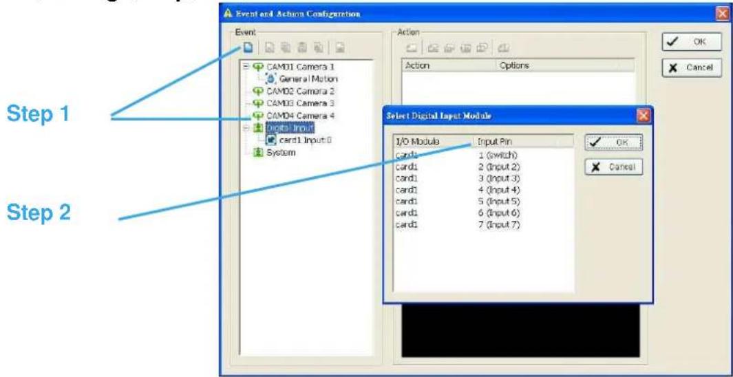
Step 1: Click and highlight Digital Input on the event type list and click Inset Event icon.
Step 2: Select the device that connected to your system, that is, the PC you are working.
Basic Setting
Enable Event: Check the box to activate.
Life Cycle
Automatic cancel event when event disappears: the alarm/action will be off once the abnormality is fixed or ends.
Manual cancel event or event last triggered: The alarm/action will continue until being cancel from the Main Console (Start>Open Event Report>Cancel All). Therefore, when the user is currently not at seat watching the screen he or she will be notified by the alarm.

Activated Period: You can set the system to react during certain time period; for example, office hours.
Event - System Event

Step 1: Click and highlight System Event on the event type list and click Inset Event icon.
Step 2: Select the Event Type (Disk Space Exhausted) and then click OK.
Basic Setting: for Disk Space Exhausted
Enable Event: Check the box to activate.
Life Cycle
Automatic cancel event when event disappears: the alarm/action will be off once the abnormality is fixed or ends.
Manual cancel event or event last triggered: The alarm/action will continue until being cancel from the Main Console (Start>Open Event Report>Cancel All). Therefore, when the user is currently not at seat watching the screen he or she will be notified by the alarm.
Activated Period: You can set the system to react during certain time period; for example, office hours.

Action
Insert Action: To setup actions responding to an unusual event.

Step 1: Choose an event and click the "Insert Action" icon.
Step 2: There are 6 types of actions: On Screen Display, Play Sound, Send E-mail, Send SMS Message, PTZ Preset Go and Signal Digital Output. Select the action you want on Action Type list and then click OK.
Step 3: Configure the setting of the Action Type if needed.
Action - Action Type
On Screen display: A red warning will be flashing on the screen of Main Console, indicating which type of unusual event is detected.
Play Sound: Sound alarm warning. Choose a Wave file (.wav) and the system will play the sound as alarm when an unusual event is detected.
Send E-mail: The system will send an E-mail immediately to given accounts indicating the type of event, the time, and attaching a picture taken while the event is detected. To give the system the E-mail accounts, go Config > Setup > Hotline. See Config at page 62 for detail.
Phone Call: The system will call a given phone number when an unusual event is detected. To setup the phone number and make an audio record for the phone call, go Config > Setup > Hotline. See Config at page 57 for detail.
PTZ Preset Go: The PTZ (pan/tilt/zoom) camera will go to a preset spot when an unusual event is detected. Select the PTZ camera on the pop-up panel, and then, at Alarm On section, select the Preset number with which you want the PTZ camera to go when an event is detected; and assign a Preset configuration for Alarm Off.
Note: You need to configure your PTZ camera before using this function. See Config at page 61 for PTZ camera configuration.

Signal Digital Output: Triggers traditional alarming devices that connect to the system, such as alarm lights and sirens.
Configuration
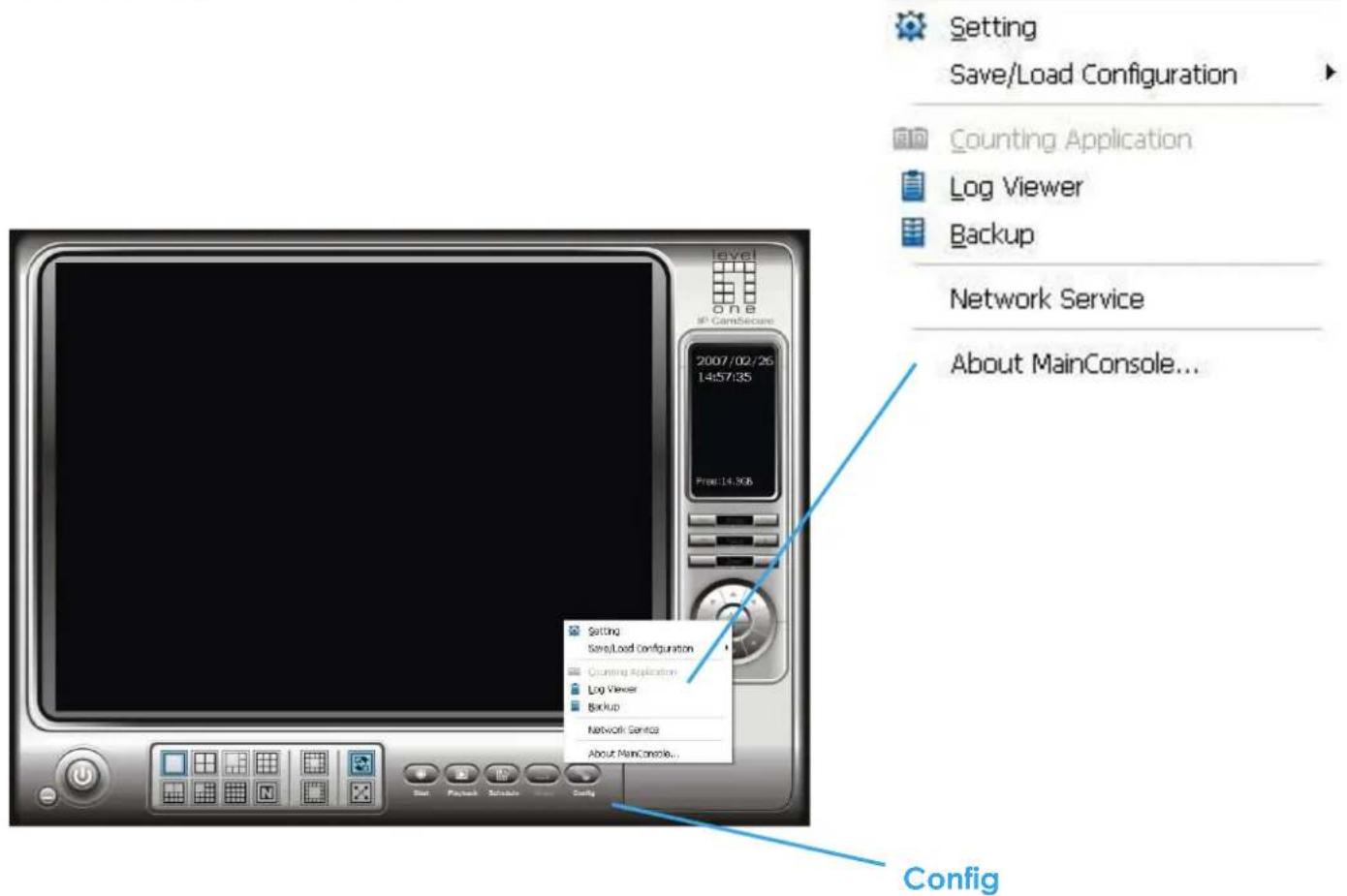
Modify the setting and access counting application, log viewer, backup, and network services. Click on the Config icon, select from the drop-down menu and open the Configuration panel.
Setting – General

Startup: Check the box and activate the functions as the system starts. You may start/stop the function in Monitor panel on the Main Console.
Panel Resolution: Set up the resolution of the control panel. You may select Auto Fit to have the system choose the best one for you.
DDNS Service: Dynamic Domain Name Server (DDNS) function allows you to monitor with IP cameras even if you have a dynamic IP address.
Click on the DDNS button to obtain the Dynamic DNS Setup panel. Set up the DDNS function by selecting the provider type, filling in user name, password and hostname, and adjusting the update period.
*DDNS Service is only in IP CamSecure Pro/Pro Plus.

Automatically Popup Event Report: Check the box to receive popup reports when there are events detected. Make sure to stop Smart Guard System before you modify the setting, otherwise the modification will not
Setting – General
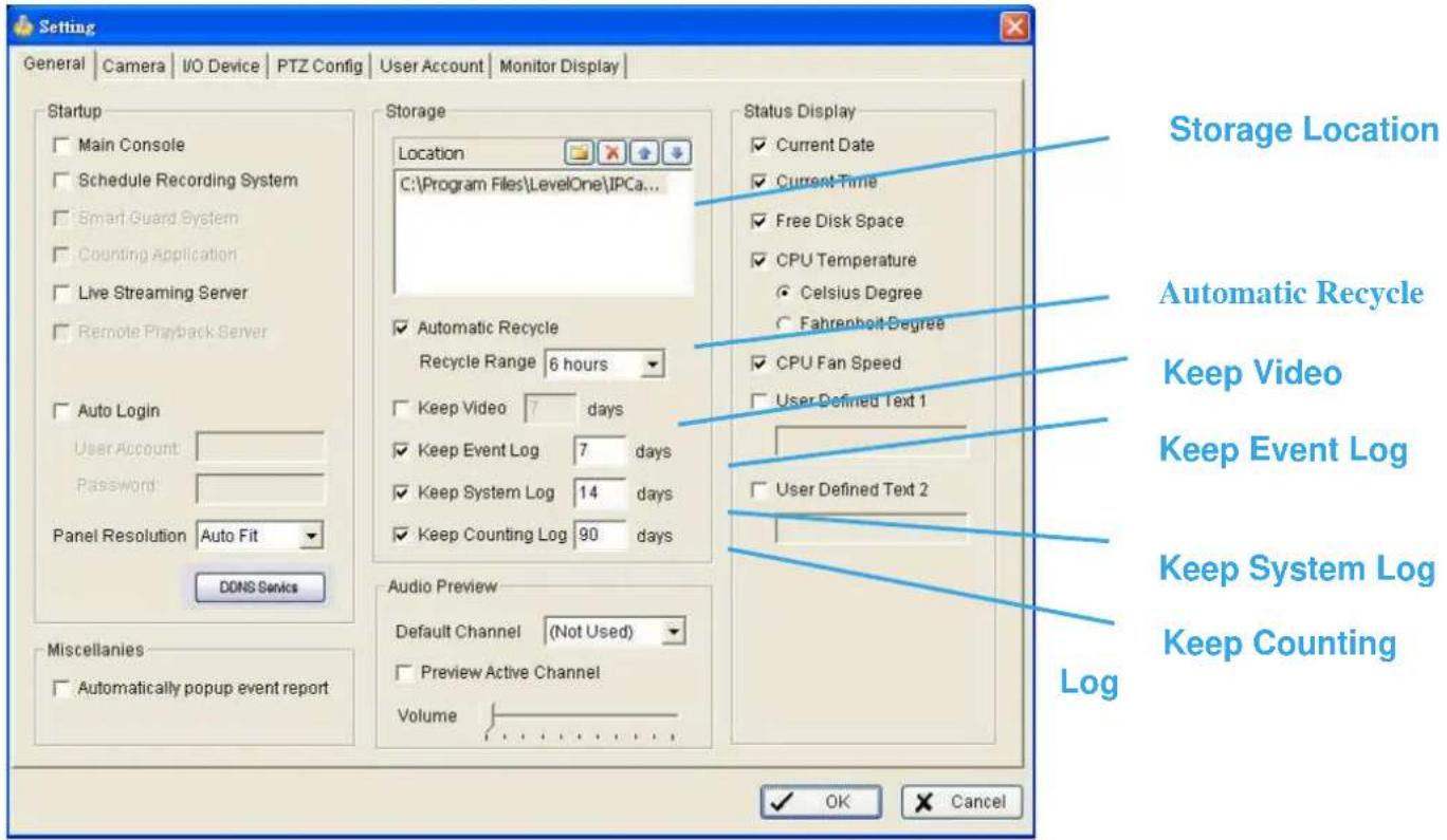
Storage Location: Assign the path and folder in which the system saves the files.
Automatic Recycle: The system will automatically delete the oldest file when the storage space is low.
Automatic Recycle: The system will automatically delete out-dated data and save storage space.
Keep Video: Deletes the video records older than the number of days set.
Keep Event Log: Deletes the event log data older than the number of days set.
Keep System Log: Deletes the system log data older than the number of days set.
Keep Counting Log: Deletes the counting application data older than the number of days set.
Setting – General
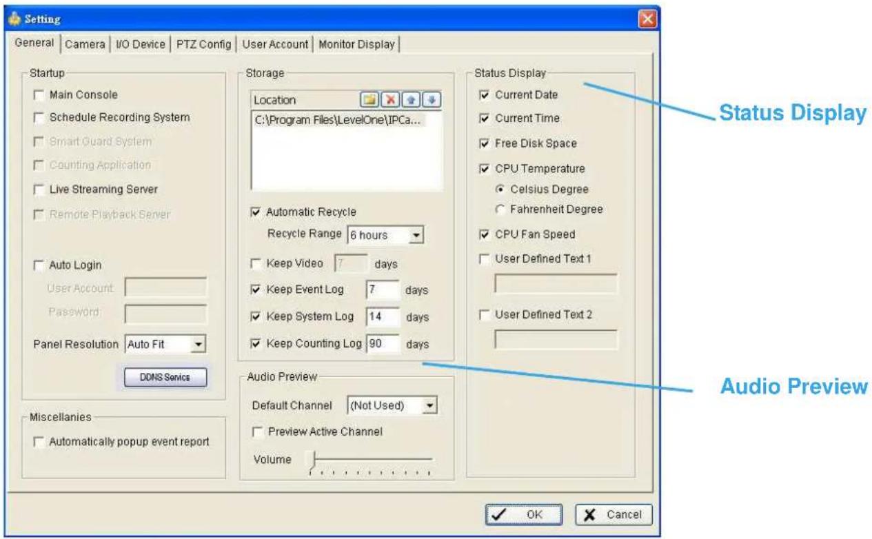
Audio Preview: Assign the audio channel to preview and the sound volume.
Status Display: Select which information you want to show on the information-display on Main Console.


Camera List: The camera(s) connected to the system will show on the panel, click the name of the camera to adjust the setting.
Camera Name: Name the camera for your convenience.
Goto Web Interface: Go to Website interface to configure the camera setting.
Camera Setting: Adjust the camera parameters in the camera setting dialog.
Video Parameter: Adjusts the video's brightness, contrast, saturation, and color hue values.
OSD Setting: Select what you want to put in the On Screen Display, showing on the sub-screen of the camera.
Setting - IP Camera

Search: Click on the Search icon to obtain the Search IP Camera panel. The system will start scanning automatically once the panel is opened; feel free to stop scanning by clicking on the Stop Scan button.
Fill in the user name and password for each IP camera found and click OK to add it to the camera list.
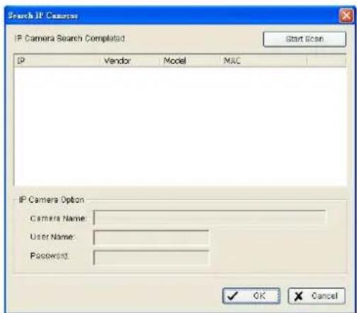
Insert: Click on the Insert icon to obtain the IP/Video Server Setting panel and add IP cameras to the list.
Delete: Click on the delete button to remove the selected IP camera(s) from the system. Click OK to finalize the modification.
Config: Click on the Config button to obtain the IP/Video Server Setting panel. You can modify the IP camera settings with the Setting panel.
Setting - IP Camera
IP/Video Server Setting panel

Network: Fill up the Network field (including Name, IP Address, Http Port, User Name, Password and Protocol) referring to the instruction provided by the manufacturer. Check "Use DNS" to use domain name instead of IP address.
Device: Choose the manufacturer of the IP camera from the pull-down menu. Click on "Auto Detect" and the model name will be shown in the box.
Description: Shows information of the IP camera.
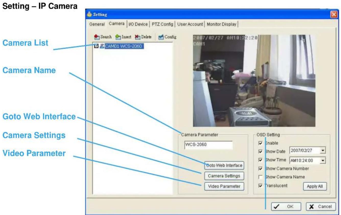
OSD Setting
Camera List: The camera(s) connected to the system will show on the panel, click the name of the camera to adjust the setting.
Camera Name: Name the camera for your convenience.
Goto Web Interface: Go to website interface to configure the camera setting.
Camera Settings: Set the camera parameter offered by camera vendor.
Video Parameter: Adjusts the video's brightness, contrast, saturation, and color hue values.
OSD Setting: Select the information that you wish to see in the on-screen display, or the sub-screen of the camera.

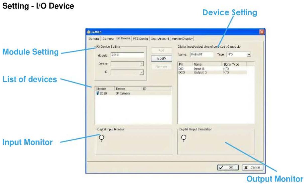
Module Setting: Name the module device and ID that has been connecting the digital input/output device(s) to your system.
Device: This column displays the device(s) already installed to the system.
ID: Select the number of the I/O port to which you plug the ribbon cable.
Input Monitor: The device(s) is turned on if the dot is in red. By triggering the digital input device, the related icon will light up. This is used to check if the device is correctly connected or not.
Output Monitor: The device(s) is turned on if the dot is in red. By clicking on the icon, you may trigger the digital device connecting to the system. This can be used to test if the output device is correctly connected.
Device Setting
Name: Insert the name of the device (input and output).
Type: Select the device type from the drop-down menu. N/O represents that the digital signal is on in normal condition; N/C represents that the signal is off in normal condition.
Setting - PTZ Config

Install the PTZ camera following the instruction of the manufacturer. The PTZ camera is usually connected to the PC with RS-485/RS-422.
Check the box on the camera list to activate the PTZ control function of a PTZ camera.
Basic Setting: Select the camera model, com port, baud rate, and address according to your PTZ camera.
Advanced Setting: You may setup the pan speed, tilt speed, zoom speed and auto pan speed. Adjust the settings by dragging the bars.
Setting – Hotline
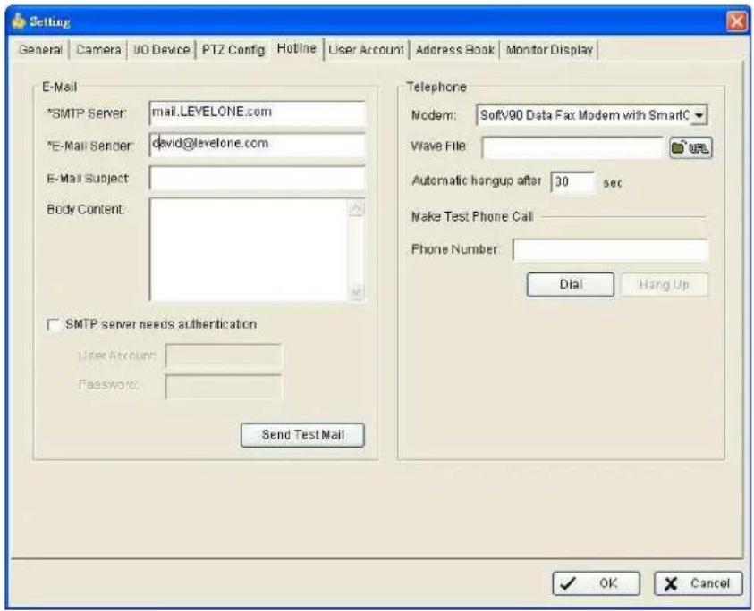
*Hotline is only in IP CamSecure Pro/Pro Plus.
Configure the settings of hotlines, including E-mail and telephone calls, once an unusual event is detected.
E-mail: Input the following information: server, sender's E-mail address, E-mail's subject title, and body content. You may click on the Send Test Mail button to test the settings.
Telephone: Select the modem that the system is going to dial the info call with, and then insert the phone number.
Note: You may select a Wave format file; it will be played in the phone to alarm the person who picks up the phone call.
* indicates mandatory areas
Setting - User Account

User Account: The administrator may manage the user accounts here. From the list on the right, highlight each account and modify the privilege setting.
Setting - Address Book

*Address Book is only in IP CamSecure Pro/Pro Plus.
Address Book: Manage the address book from which you want to give a call or E-mail when an unusual event is detected.
Setting
Monitor Display

Playback Option: Execute Playback on the secondary monitor by checking the box. Make sure to adjust the display setting of your computer in advance to avoid system error.
Cameras List: The left side displays a list of all cameras; modify the cameras shown on primary/secondary monitor in the right window.
*The dual monitor is only in IP CamSecure Pro/Pro Plus.
Auto Scan: Activate auto scan to rotate the channels/ cameras on the display screen.
For instance, you may select to show only 4 sub-screens on the main console while having 16 channels connected to the system. With auto scan function, you will be able to see all 16 channels by turns. You can set up a primary channel that will always be on the screen and a secondary channel that has secondary priority.
Layout: Choose the number of divisions for NxN division on the Main Console screen.
Save/Load Configuration
The Save/ Load Configuration function allows system users to save any specific setting as a cfg (config) file. You may save up several different cfg files at any time.
Save Configuration: To save a specific setting, go to Config > Save/ Load Configuration > Save. In the popup window, type in the file name and then save it as a cfg file.

Load Configuration: To load a specific setting, go to Config > Save/ Load Configuration > Load. In the popup window, go to the directory that you saved the cfg files at, select any one of them and then click OK to load the file.
Video Source
When you use LevelOne CamCon Capture Card series, like FCS-8004, you need to set up your video source before you start to activate schedule recording.

Video Standard: Select the Standard that you apply, from NTSC and PAL.
Video Resolution: Select the resolution you want, from 320 x 240, 640 x 240 and 640 x 480.
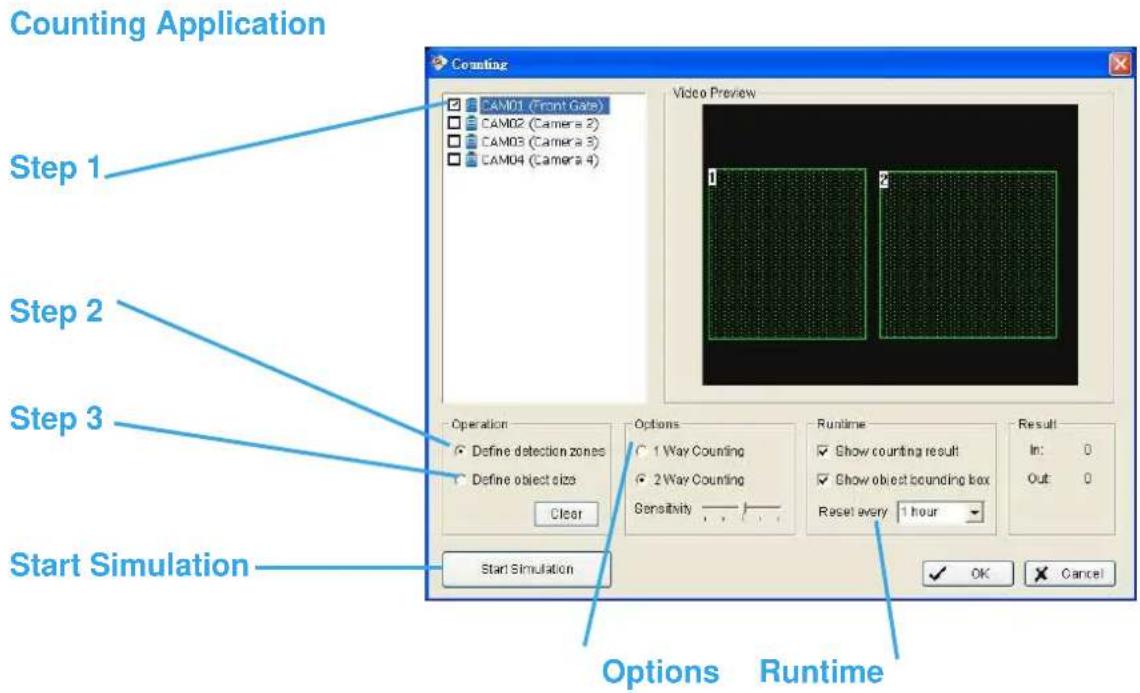
*Counting Application is only in IP CamSecure Pro/Pro Plus.
Step 1: Check the box of the camera to apply the Counting Application on it.
Step 2: In Operation section, define the detection zones you want. Drag the cruise to draw Region 1 and Region 2
Step 3: Define the object size on the screen. Objects in the size going across these two Regions will be counted.
Options: 1 Way Counting will take objects going from Region 1 to Region 2 as one count. In 2 Way Counting mode, it counts either going from Region 1 to Region 2 or Region 2 to Region 1.
Runtime: Check the boxes to show the counting result on the screen or/and show object bounding box, which draws the shape of the object that the system detects in red squares. You can choose from the full-down menu of how long you want to reset the counting number.
Start Simulation: Click to test the setting.
Log Viewer
*IP CamSecure Lite only has System Log option in Log Viewer.

Unusual Event: You can check out the history of Unusual Event that had been detected by Smart Guard System.
Step1: Choose the type of event you want to check or select "All" on the pull-down menu for all types of events.
Step 2: Choose from which camera you want to check the event(s) or select "All" for all the channels available.
Step 3: You can either view the events on a particular date or during a given time period. To search and view Unusual Event on a particular date, mark the box right after "Date" and indicate the date you want to check.
You may also point out two different time points and search for Unusual Event between them. Mark the box in the Date &Time column and then enter the date and time.
Step 4: Click Search
Log Viewer
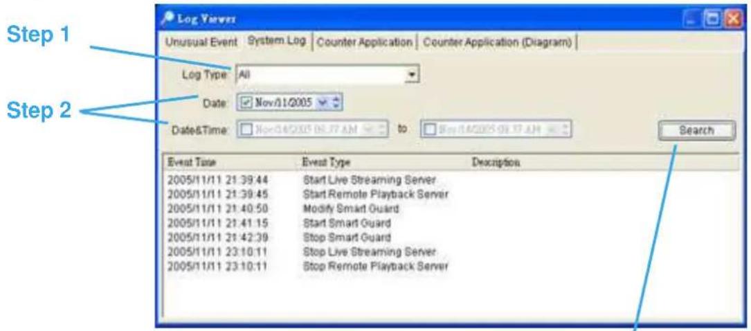
Step 3
System Log: You can choose the log type from the drop-down menu, following is a complete list of all log types:
- Main Console Startup
- Main Console Shutdown
- User Login
- User Login Failed
- Start Schedule
- Stop Schedule
- Execute Recycle
- Execute Backup
- Enable Channel
- Disable Channel
- Start Smart Guard
- Stop Smart Guard
- Modify Smart Guard
- Modify Schedule
- Modify Configuration
- Start Live Streaming Server
- Stop Live Streaming Server
- Modify Live Streaming Server
- Start Remote Playback Server
- Stop Remote Playback Server
- IP Camera Connection Lost
Step1: Choose the type of event you want to check or select "All" on the pull-down menu for all types of events.
Step 2: You can either view the events on a particular date or during a given time period. To search and view Unusual Event on a particular date, check the box right after Date and indicate the date you want to check. You may also point out two different time points and search for Unusual Event between them. Mark the box in the Date & Time column and then enter the date and time.
Step 3: Click Search.
Log Viewer - Counting Application
Counting Application:
Display the history of Counting Application during a given time period.

Step1: Select the channel you want to check or select "All" from the drop-down menu for all channels.
Step 2: You may view events happened on a particular date or during a given time period. To search and view unusual event happened on a particular date, mark the box right next to “Date” and indicate the date. You may also point out two different time points and search for unusual events happened during the period. Mark the box in the Date&Time column and then enter the date and time.
Step 3: Click Search.
Log Viewer - Counting Application (Diagram):
Counting Application (Diagram):
Display the Counting Application data in diagram format.

Step1: Select the channel you want to check or select "All" from the drop-down menu for all channels.
Step 2: From the drop-down menu, set up how you would like the diagram to be displayed. You have the options of one day, one month, or one year.
Step 3: Select a specific date to make it the start point of the diagram.
Step 4: Click Search.
Backup
The backup function saves video record and other log information. User may open backup files on any PC with Windows Operation System and operate the full function Playback panel on it. Follow the instructions below to obtain backup files.
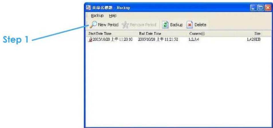
Step 1: Click on "New Period" to obtain the Select DateTime Period panel.
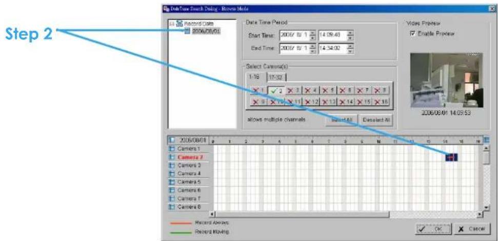
Step 2: From the record date section, select the date you want to backup from. You will see color lines appear in the time table implying available data recorded. Red, green, and blue stands for record always, record on motion, and record on event data files, respectively.
Backup
Step 4

Step 3: Select the data you want to backup by highlighting the time period. Besides the time-table, you may also set up start time and end time in the Date Time Period section.
Step 4: Click on the camera number icon to add camera(s) or click Select All to add all the cameras.
Step 5: Check the box of Enable Preview to get the preview of the video you select.
Step 6: Click OK when the settings are complete and go back to the Backup panel.
Backup
Step 7

Step 7: Click the Backup icon and you can see the size of the file.
Step 8: Choose the path you want to save the file or, burn the file into a CD (direct CD burning for Windows XP only).
Step 9: Select which log information you want to backup (Event Log, System Log and/or Counter Log) and then click OK.

Delete recorded information from the system
Step 1: Click on "New Period" to obtain the Select DateTime Period panel.
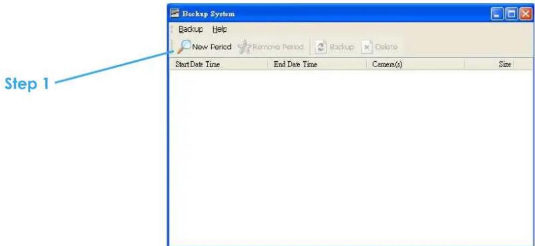
Step 2: From the record date section, select the date you want to delete the file from. You will see color lines appear in the time table implying available data. Red, green, and blue stands for record always, record on motion, and record on event data files, respectively.
Step 3: Select the data you want to delete by highlighting the time period. Besides the time-table, you may also set up start time and end time in the Date Time Period section.
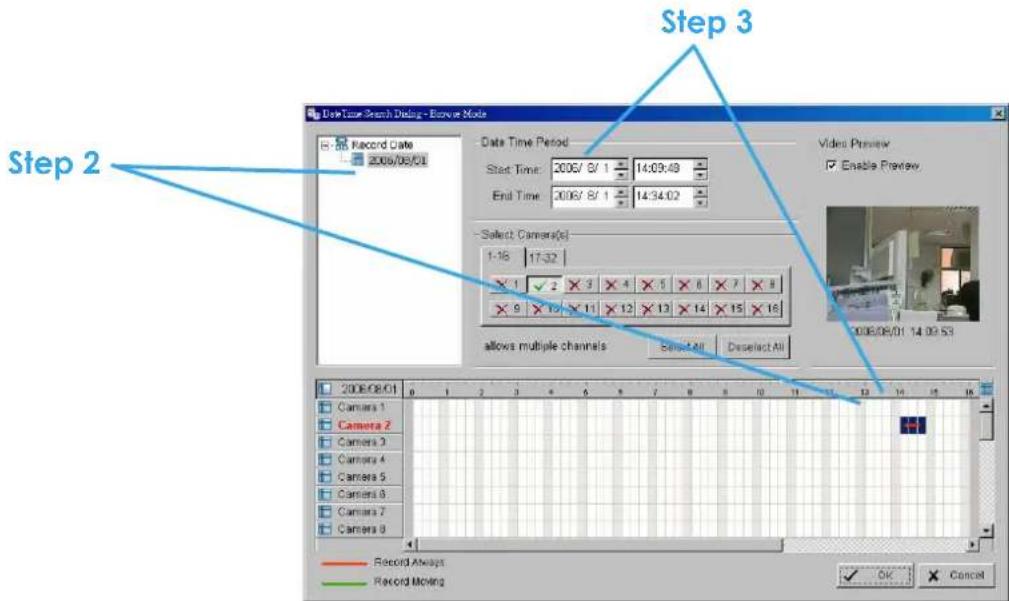
Step 4: Click on the camera number icon to add camera(s) or click Select All to add all the cameras.
Step 5: Check the box of Enable Preview to get the preview of the video you select.
Step 6: Click OK when the settings are complete and go back to the Backup panel.

Step 7: Click on the "Delete" icon and delete the data.

Network Service
There are 3 types of network services: live streaming server, remote playback server, and 3GPP service. From the Main Console, go to Config > Network Service to obtain the Network Service panel.
*IP CamSecure Lite only has Live Streaming in Network Service.

Live Streaming Server
When starting the live streaming function of your computer, you allow other people to log on to the specific computer and view cameras that are connected to it. As system administrator, you are able to monitor these accounts in order to maintain the system efficiency.
Live Streaming Server – Main
On Live Streaming Server panel, you can see the clients who are currently logging on to your computer and watching the live video from the remote side.
Start: By starting the system, you turn the computer into a live streaming server; thus allow other people to log on to the system.

Kill Client: Highlight an IP address and click on the "Kill Client" button to block a client from your system.
Kill All Clients: By clicking on this button, you may block all the clients logging to your system.
Stop: Stop broadcasting live stream video.

Options: You may only adjust the setting when the server is stopped.
Port: Assign a port for the clients to connect to your system to the network.
Use Default Web Server: Activate the Web server by checking the box; clients will be able to watch live video via Internet Explorer. The port is set to 80 by default.
Maximum Users: Number of connections that are allowed to connect to your system. One camera video counts as one connection.
Save Log: Save the log information at appoint folder.
Live Streaming Server - Black/White List

White List: Check the box to activate White List filter. Only IPs from the White List are allowed to log-in.
Black List: Check the box to activate Black List filter. IPs from the Black List will be blocked.
IP Field: Enter the IP in the field at the left or, 2 sets of IP to indicate a series of IPs.
Add/Delete: To Add the IP(s) onto the list or remove it from the list.
Apply to All Network Servers: To apply the setting to all the servers.
Live Streaming Server – Performance
Total bitrate
Individual Camera bitrate
![Live Streaming Server Main Black/White List Performance Total bitrate: 195.9Kbps Camera 1 bitrate: 6.7Kbps [2005/12/05 14:56:24] User Login: admin Accept [2005/12/05 14:56:24] Play CAM 1: admin [2005/12/05 14:56:29] Play CAM 2: admin [2005/12/05 14:56:31] Play CAM 3: admin [2005/12/05 14:56:33] Play…](/content/2026/06/1185311/images/74373dec1ec979e2aff47c6d54a44710e9b1d01d217c9207046be04e2414e79f.jpg)
Live Streaming Server log information
Remote Playback Server

*Remote Playback is only in IP CamSecure Pro/Pro Plus and there are up to 16 channels displayed simultaneously.
When starting the remote playback function of your computer, you allow other people to log on to the specific computer and withdraw data files that are stored on it. As system administrator, you are able to monitor the accounts that log on in order to maintain the system efficiency.
Remote Playback Server - Main
On Remote Playback Server panel, you can see the clients who are currently logging on to your computer and watching the live video from the remote side.
Start: By starting the system, you turn the computer into a remote playback server; thus allow other people to access the system.
Kill Client: Highlight an IP address and click on the "Kill Client" button to block a client from your system.
Kill All Clients: By clicking on this button, you may block all the clients logging to your system.
Stop: Stop broadcasting playback video.
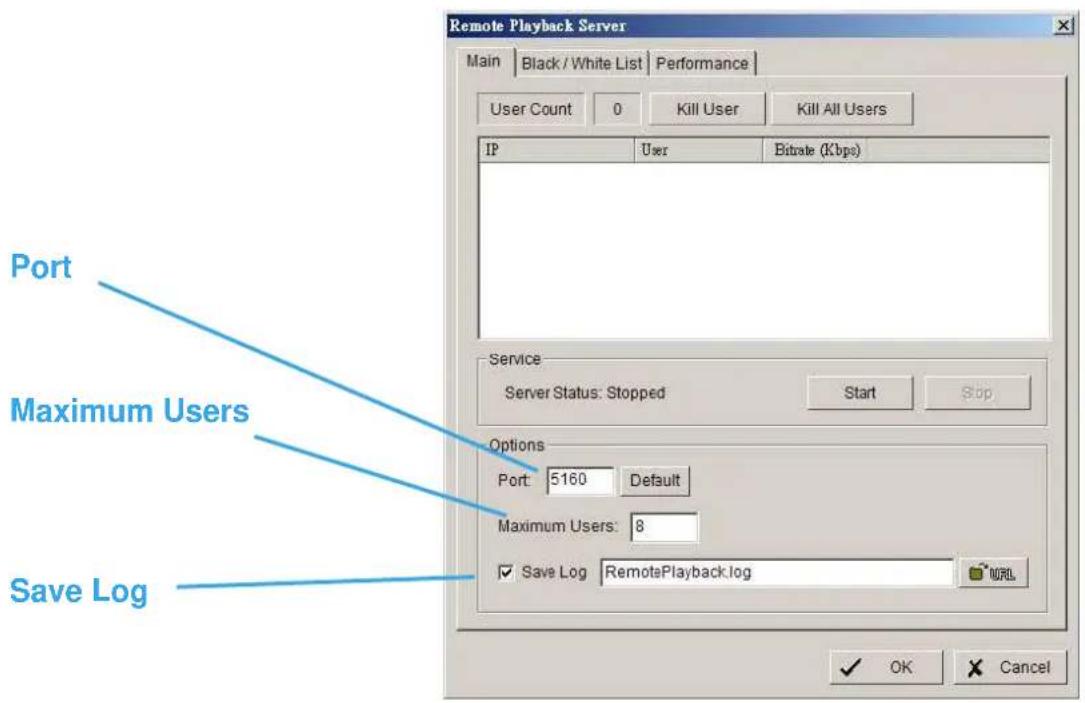
Options: You may only adjust the setting when the server is stopped.
Port: Assign a port for the clients to connect to your system to the network.
Maximum Users: Number of connections that are allowed to connect to the Remote Playback Server. One camera video counts as one connection.
Save Log: Save the log information at appoint folder.
Remote Playback Server - Black/White List

White List: Check the box to activate White List filter. Only IPs from the White List are allowed to log-in.
Black List: Check the box to activate Black List filter. IPs from the Black List will be blocked.
IP Field: Enter the IP in the field at the left or, 2 sets of IP to indicate a series of IPs.
Add/Delete: To Add the IP(s) onto the list or remove it from the list.
Apply to All Network Servers: To apply the setting to all the servers.
Remote Playback Server – Performance
Total bitrate
Individual Camera bitrate
![Live Streaming Server Main Black/White List Performance Total bitrate: 195.9Kbps Camera 1 bitrate: 6.7Kbps [2005/12/05 14:56:24] User Login: admin Accept [2005/12/05 14:56:24] Play CAM 1: admin [2005/12/05 14:56:29] Play CAM 2: admin [2005/12/05 14:56:31] Play CAM 3: admin [2005/12/05 14:56:33] Play…](/content/2026/06/1185311/images/7e77c67ee721cfe552ca4ac637499bbca037d0f2e3abca66f342c62fa8e7324a.jpg)
Remote Playback Server log information
About
Click About on the pull-down menu, and then the version of IP CamSecure will show up on the screen.
E-Map

With E-Map, user can find out or track the actual location and alarm status easily and receive instant response when the event happens.
The arrows and lightening icon on E-Map represent cameras and I/O devices and these icons will turn red once they are triggered by alarms.
To launch E-Map application, simply click on Start and select Open E-Map from start menu to open E-Map window.
There are 2 modes in E-Map application:
Edit mode: Allow users to add/edit maps and indicators of devices. In Edit mode, the function buttons on the bottom of the window will be active, and then setup the configuration before running E-map function at the first time.
Operate mode: all settings will be activated in this mode.
Edit Mode
To carry out edit function, you need to be in Edit mode.

6.1.1 Add/Edit/Delete Map
Add E-Map:
Step 1: Make sure being in "Edit Mode" and all devices are connected and inserted.
Step 2: Right click on the Map 📋 icon in device and map list to obtain the option menu to add map, or just click "Add Map" button to obtain the "Map Config" dialog.

Step 3: Select the map file and insert the map name. Click OK, and then the map you added appears in the tree structure of device and map list.
Step 4: The map indicator appears on the left-up corner of parent map. Drag it to the position you want on appointed map.
Edit E-Map:
Step 1: Make sure you are in Edit mode and all devices are connected and inserted.
Step 2: Right click on the "Map 🔔" icon to obtain the option menu to edit map, or just click "Edit Map" button to obtain the "Map Config" dialog.
Step 3: Modify the required details, and then click OK to save configuration.
Delete E-Map:
Step 1: Make sure being in Edit mode and all devices are connected and inserted.
Step 2: Right click on the "Map 🔍" icon to obtain the option menu to delete map, or just click Delete button to remove appointed map from list.
Note: The root map can't be deleted.
6.1.2 Add/Rotate/Delete Device Indicator
Add Indicator:
Step 1: Make sure being in Edit mode and all devices are connected and inserted.
Step 2: Select on the icon "Map" which you want add device indicator to.
Step 3: Before adding indicator, ensure that the map you want is displayed. Select device from list and directly drag a device to the desired location on the map.
Note: Different device is symbolized by different indicator.
- Camera indicator, -digital Input indicator, -POS indicator.
Rotate Indicator:
Step 1: Ensure being in Edit mode and all devices are inserted. Select device indicator from map or form Device and Map list. The device indicator will be marked with a green
ring
Step 2: Click Rotate button, the indicator will rotate 45 degree.
Note: Only camera indicators are allowed to be rotated.
Delete Indicator:
Step 1: Ensure being in Edit mode and all devices are inserted. Select device indicator from map or from Device and Map list. The device indicator will be marked with a green
ring
Step 2: Click Delete button, the indicator will be gone.
Operate Mode
To carry out the operation functions in E-Map, you need to be in Operate mode.

Operate mode/ Edit mode Switch button
a. Device and Map Tree list
This window will list all devices and map hierarchies; click device or map indicator to show related information on E-Map windows.

Map – Select the map you want to show on E-Map Window.

Camera – Select the camera you want to preview video on preview window and mark indicator on E-map.

Digital Input – Select it to highlight the device with green ring on map and show status on Information window. If the Digital Input is from IP camera, the preview window will display live video of the camera.

Digital Output – Select it to highlight the device with green ring on map and show status on
Information window. If the Digital Output is from IP camera, the preview window will display live video of the camera.

POS – Select it to highlight the POS device with green ring on map and display live video of first associated camera on preview window.
b.E-Map picture
This window will show the map layer and indicators.
Device Indicator:
Select device indicator from Device and Map Tree list to show preview video and related information.
Map indicator:
Select map indicator will enter the next map layer. If you want move to upper layer, right click on the map to select Up option or click right on the map layer
c.Information and Preview window
This window will show the related information of each indicator.

Map Info – Show map name.

Camera – Show camera name and connecting status.

Digital Input – Show Digital Input name and status (0 or 1).

Digital Output –Show Digital Output name and status (0 or 1).

POS – Show POS device name, connecting status, first associated camera name and connecting status.
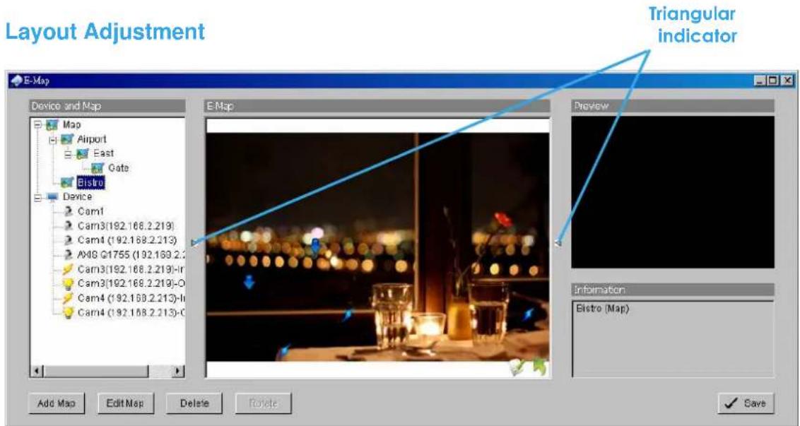
Shrink the window:
Click “ ▶ Triangular indicator” to hide the Device and Map/Preview and Information window on right and left side, click triangular indicator again to go back to default setting.
Full screen display:
For the system with Dual-Monitor, user can view the MainConsole on primary monitor, and view the full-size E-Map on secondary
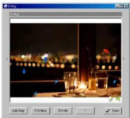
monitor.
Step 1: Click “▶ ▶ Triangular indicator” to hide the Device and Map/ Preview and Information window on right and left side.
Step 2: Click “☐” on right top of the window, and then get the full screen mode of E-Map.
Live Viewer
Live Viewer
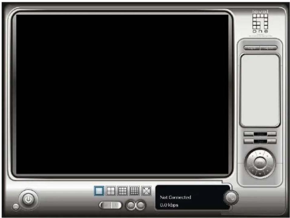
With the Live Viewer console, you may watch real-time video from remote live streaming servers.
*There is only 1 channel displayed in Live Viewer in IP CamSecure Lite while there are up to 16 channels displayed in IP CamSecure Pro/Pro Plus simultaneously.
Live Viewer

Click on the Setup icon to obtain the Setup panel

Live Viewer
Setup Panel—Group
You may put different cameras into the same group when utilizing the Live Streaming Server function.
Step 1: Go to the Group tab of the liveView Setting panel.
Step 2: Log in to all the servers that contain the camera(s) you would like to put into the group(s).
Step 3: Click "Insert" to create a new group; name the group for future reference.
Step 4: From the window at the right, highlight the camera(s) that you would like to add to a group and then click on the “<--” button. Repeat the process until you are satisfied with the group setting.
Step 5: Click on the Delete and Rename button to remove or rename a specific group.
Step 6: Repeat Step 3 to 5 until you are done with creating and setting groups.
Step 7: Click OK.

Live Viewer
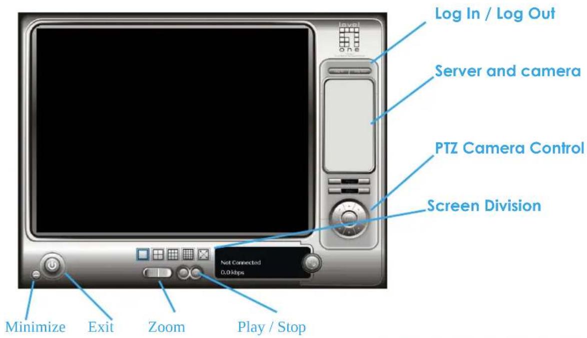
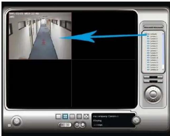
Select a camera(s) from the server/camera list on the right and then drag it to where you want the image to be displayed.
On the server/ camera list, right click on a camera to connect/ disconnect it.
Log In/ Log Out: Select a server or a group and click on the log in/ out icon to access/ leave the server. You may also log in/ out from the server by right clicking on it.
Server and Camera List: Display a complete list of the server(s) and camera(s) that are added to the system.
PTZ Camera Control: You may control the camera view by utilizing the PTZ camera control panel to adjust the camera's view. This is only available with cameras that support PTZ function.
Minimize: Minimize the Live View Console window.
Exit: Shut down the system or log out current user.
Zoom: Click on the + and - signs to zoom in and out the view.
Play / Stop: Select a camera/video and click Play / Stop to play/stop the particular channel.
Live Viewer
Other—View Real-Time Video on the Internet

*There is only 1 channel displayed in Live Viewer via web browser in IP CamSecure Lite while there are up to 4 channels displayed in IP CamSecure Pro/Pro Plus simultaneously.
Server IP: Open an Internet Explorer and enter the IP number of the server followed by the connecting port.
Example: http://192.168.10.169/
Connect / Disconnect: Select the camera from the server, hold the left click and drag the camera to where you want to put the image, or double click the camera on the list to connect it.
Select the camera on screen or on the list and click the Disconnect icon to disconnect the camera.
Play / Stop: Select a camera/video and click Play / Stop to play/stop the particular channel.
DBTools
DBTools
The DBTools : Export/import database/files; export configurations and edit storage location.
Step 1: Execute DBTools from program files.

Step 2: Enter the password of administrator to login.

Export database
Step 1: Select the database you want to export.
Step 2: Select the destination you want to export.
Step 3: Press "Export" to start to export database.

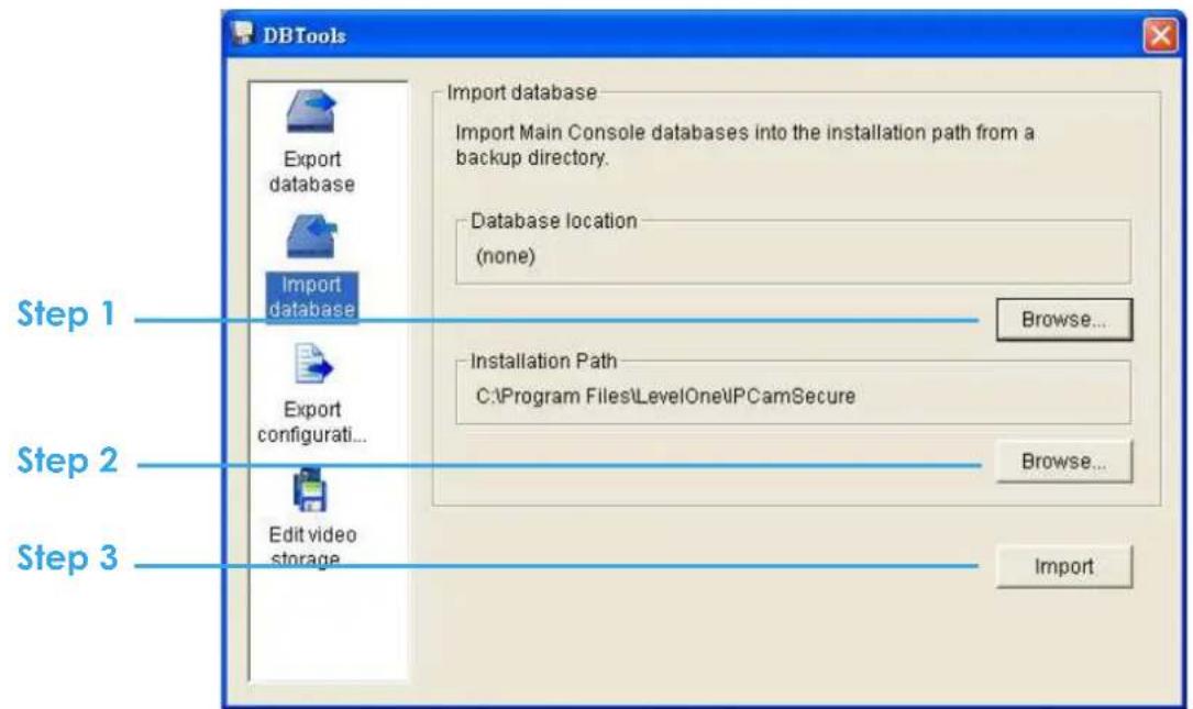
Import database
Step 1: Select the database location you want to import.
Step 2: Select the installation path you want to import.
Step 3: Press "Import" to start to import database.
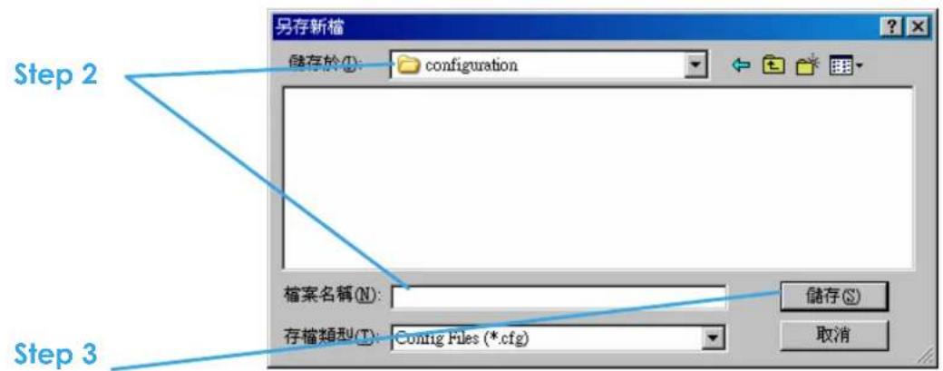
Export configurations
Step 1: Press "Export".

Step 2: Select the location you want to Export and type the name of the configurations.
Step 3: Press "Save" to start to import database.
Edit storage location
If you move the recorded videos to a new directory, to ensure the videos can still be recognized by the Playback system, you should change the original directory.
Step 1: Select the original directory in the table.
Step 2: Type the new path you want to save the recorded videos.
Step 3: Press "Update" to finish editing storage location.

Backup
The backup function saves video record and other log information. Users may open backup files on any PC with Windows Operation System and operate the full function Playback panel on it. Follow the instructions below to obtain backup files.
Step 1: Execute DBTools from program files.

Step 2: Click on "New Period" to obtain the Select DateTime Period panel.
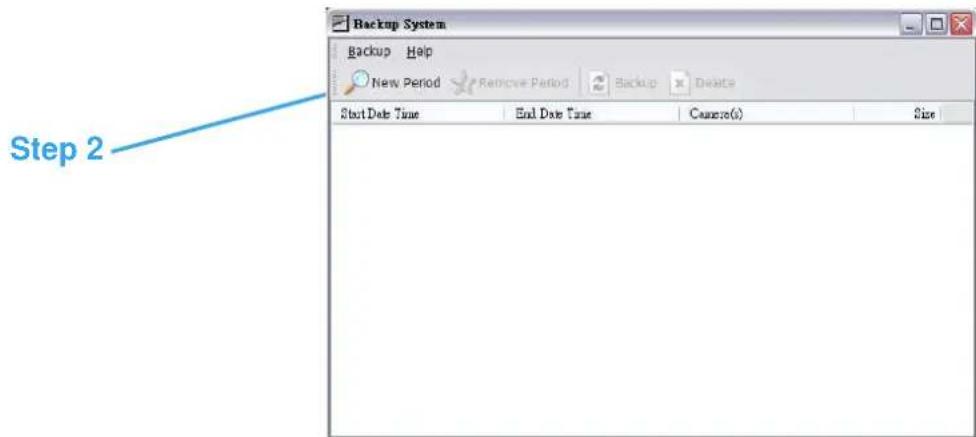
Step 3: From the record date section, select the date you want to backup from. You will see color lines appear in the time table implying available data recorded. Red, green, and blue stands for record always, record on motion, and record on event data files, respectively.
Step 4: Select the data you want to backup by highlighting the time period. Besides the time-table, you may also set up start time and end time in the Date Time Period section.
Step 5: Click on the camera number icon to add camera(s) or click Select All to add all the cameras.
Step 6: Check the box of Enable Preview to get the preview of the video you select.
Step 7: Click OK when the settings are complete and go back to the Backup panel.

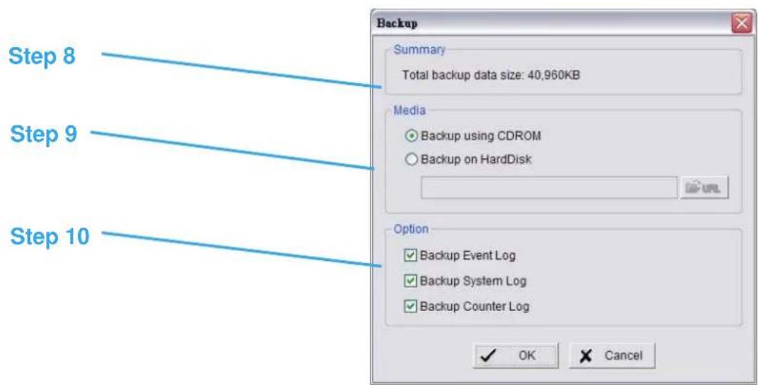
Step 8: Click the Backup icon to see the size of the file.
Step 9: Choose the path you want to save the file or burn the file into a CD (direct CD burning for Windows XP only).
Step 10: Select the log information you would like to backup (Event Log, System Log and/or Counter Log) and then click OK.
Delete recorded information from the system
Step 1: Click on "New Period" to obtain the Select DateTime Period panel.
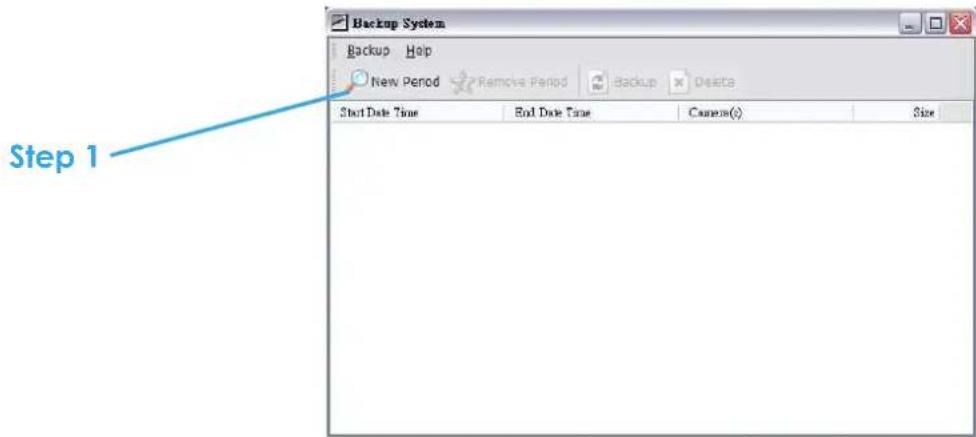
Step 2: From the record date section, select the date you want to delete the file from. You will see color lines appear in the time table implying available data. Red, green, and blue stands for record always, record on motion, and record on event data files, respectively.
Step 3: Select the data you want to delete by highlighting the time period. Besides the time-table, you may also set up start time and end time in the Date Time Period section.

Step 4: Click on the camera number icon to add camera(s) or click Select All to add all the cameras.
Step 5: Check the box of Enable Preview to get the preview of the video you select.
Step 6: Click OK when the settings are complete and go back to the Backup panel.

Step 7: Click on the "Delete" icon and delete the data.
Note: the deleted video cannot be recovered.

Appendix A - 3GPP Service
How to setup 3GPP streaming connection (using BenQ-Siemens mobile phones)
System Configuration
| LEVELONE IP CamSecure server v1.xx | |
| CPU: Intel core2 Duo 1.86 GHz | |
| Memory: 512 DDR RAM | |
| Ethernet: Realtek RTL8168/8111 PCI-E | |
| Hard Disk: 160GB | |
| Graphic card: ASUS | Extreme AX550 |
| Operating System: | Windows XP Professional SP2 |
| Mobile Phone: BenQ | Siemens E81 |
1.1 Configuration from LEVELONE server
Step 1: Go to Config and select Network Service

Step 2: Select 3GPP Service, and then click Start
Note: In the Option item, the "port" selected here is the same port from mobile handset

1.2 Configuration from 3G Mobile Phone
1.2.1 BenQ-Siemens E81
Step 1: Go to Menu, then Internet
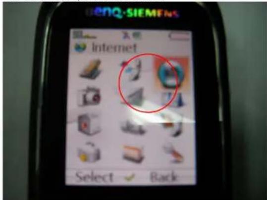
Step 2: Select Bookmarks

Step 3: Add New Bookmark
Step 4: Configure the Adress setting as the following example.
Ex: rtsp://61.216.97.69:554/media00.3gp
61.216.97.69:554 is the IP address of LEVELONE IP CamSecure system
Port : port specified in 3GPP Service from LEVELONE IP CamSecure system
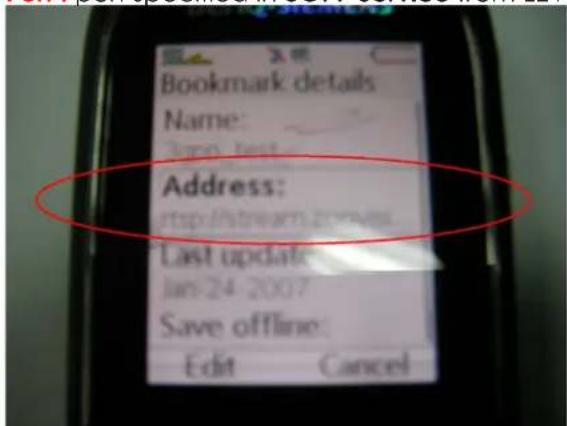
Step 5: Save the settings and start playing
1.2.2 BenQ P50
Step 1: Connect GPRS
Step 2: Download and install the [PLATFORM4] software.
Step 3: Execute the Main Console.
Step 4: Press the [Config] → [Network Service] → [Start]
Step 5: Open [PLATFORM4], press the button framed by red into Option
Step 6: [Open URL] enter the RTSP address of the camera
EX: rtsp://61.216.97.69/media00.3gp→channel 1
EX: rtsp://61.216.97.69/media01.3gp→channel 2
EX: rtsp://61.216.97.69/media02.3gp→channel 3
Step 7: [Setting I]change the setting and press "OK"
[Protocol] TCP
[Buffer Size] 60
[Connection TimeOut] 103
[Data Recept.TimeOut] 100
[Deblocking Filter] check
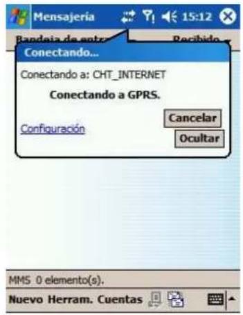
Step 7

Step 8: Go back to PLATFORM4, searching and get the video.
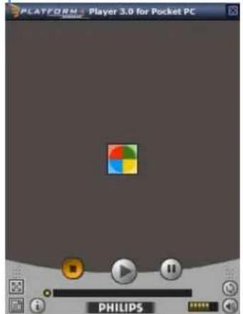

Appendix B – PDA / Smart Phone Client
PDA / SP (Smart Phone) Client are only applied for devices with Windows Mobile 5.0 platform or above. See the sections below to find how to install and execute PDA / SP Client.
Note:
- The different between Smart Phone and PDA Client is navigation of operation, user can only control client with phone buttons.
- The resolution of PDA / SP Client is limited in 240*320 (QVGA).
1.1 Install PDA / Smart Phone Client
Step 1: Connect mobile device to the PC.
Step 2: Insert the installation CD and click on PDA Client Installation / Smart Phone Client Installation to install application in device.
Note: If you do not have Microsoft® ActiveSync installed, a message will appear "Cannot find ActiveSync. Please reinstall ActiveSync and then run this installation again."
Step 3: Check the client application is installed completely in the mobile device.

1.2 Execute PDA / Smart Phone Client
1.2.1 Main Console setting
Step 1: Go to Config and select Network Service

Step 2: Select "Live Streaming", and then click "Start".
Note: The "Port" selected here will be the same with the one in PDA/Smart Phone.

1.2.2 Execute and Login
Step 1: Make sure your PDA/Smart Phone device is connected to network, and then go to Start - Programs - LEVELONE PDA/Smart Phone Client to execute application.

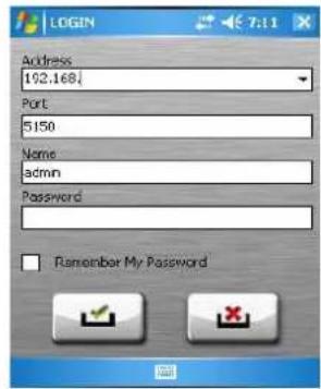
Step 2: Insert Address, Port, Name and Password of the server and click on 📄 to login.
1.3 PDA/Smart Phone Client Overview
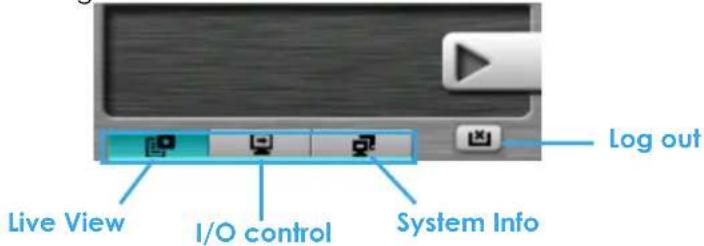
There are 3 main pages of Client application: Monitor Preview, I/O Control and System Info. Switch between these buttons to adjust overall configuration.
1.3.1 Live View

Camera List:
Display Live Video
Back to Camera List
Displays all "snapshots" of channels connected to server as camera list. Click on indicated snapshot to get the channel information, and then click on to display live video.
Note: The Screen Division and Refresh option could help to quick find the channel.
Screen Divisions

Refresh
Live Video Display:
Live View panel could display "live video", control PTZ, and snapshot. Click 📋 to go back camera list. PTZ Control: Click on PT Control Panel and Zoom Out/In to control physical PTZ camera or adjust digital PTZ under digital PTZ mode.
Note: To switch between "Digital PTZ" and "Physical PTZ", simply click on button.

Preset Go: Click to select indicated preset point.

Snapshot: Click to take the snapshot and save it to default folder.
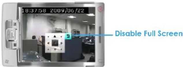
Full Screen: Click H to toggle to the "Full Screen Mode", right click on screen to obtain the PT control panel and disable full screen display.
Enable Audio: Click 📄 to enable the audio of current channel.
1.3.2 I/O Control
Select "I/O Control" button to monitor status of DI/DO devices, and control DO devices.

I/O Device list:
Select and monitor the device connected with Server.
DI/DO status:
Monitor the DI/DO status synchronized with Server, and then click Output button to trigger the DO action.

Gray icon indicates the normal status of DI/DO devices.

Red icon indicates the alarm status of DI/DO devices.

Green icon indicates the synchronization process.
1.3.3 System Info
Display the server and client information. Server information includes address, post, and version. Client information includes login user, count of camera and I/O device with access authority and version.

Appendix C – I-Phone Browser
LEVELONE Live Streaming service could handle the request form I-Phone browser. Below section will guide hot to use this feature with I-Phone device.
1.1 Configuration from LEVELONE server
Step 1: Go to "Config" and select "Network Service"
Network Service

Step 2: Select "Live Streaming", and then click "Start".
Note: The "Port" selected here will be the same as the web live view and web playback.
Live Streaming
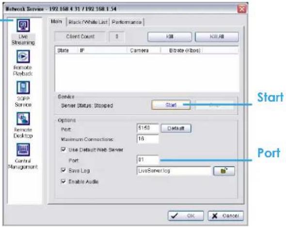
1.2 Connect to LEVELONE server
Step 1: Make sure the I-phone is connected to the internet. Open Safari browser and enter the IP address or
DDNS "name" of the server followed by the connecting port.
Example: http://192.168.1.16:8080/
Note: 192.168.1.16 is the IP address of the server.
8080 is the port specified in "Use Default Web Server" in Network Service.
Step 2: Enter user name and password to login LEVELONE
MainConsole Server, select camera to view live video.
1.3 Live Display
To view live video, select camera from list, use touch panel to zoom in the video.
To switch video, please click to back to list and select another camera to view the video.
1.4 PTZ Control
With cameras that support PTZ function, the PTZ panel will show as picture. User can control camera to pan, tile and zoom in/zoom out manually, or move to pre-set location by select PTZ preset point from drop down list.
![iPad 下午3:18 192.168.1.92/Camera... Yahoo! 目 [+] [+] + 2](/content/2026/06/1185311/images/e9ecc99a1dfab60b8175c65c614fe4236e72cfd991b9ac810bc9dc2c0b81a161.jpg)
- INDEX
- INSTALLATION....4
- MAIN CONSOLE....6
- PLAYBACK....11
- SCHEDULE....28
- GUARD 34
- CONFIGURATION ....53
- NETWORK SERVICE....78
- E-MAP 86
- LIVE VIEWER 91
- DBTOOLS 96
- BACKUP....100
- APPENDIX A - 3GPP SERVICE....104
- APPENDIX B – PDA / SMART PHONE CLIENT ....107
- APPENDIX C - I-PHONE BROWSER 111
- INSTALL IP CAMERA(S)
- INSTALL CAPTURE CARD(S)
- INSTALLATION
- IP CAMSECURE INSTALLATION
- CUSTOM SETUP TYPE
- MAIN CONSOLE
- ON SCREEN MENU
- PLAYBACK
- DAY-TIME PANEL
- TO WITHDRAW THE RECORD
- SEARCH MODE
- UNUSUAL EVENT - GENERAL MOTION
- INTELLIGENT SEARCH TOOL PANEL
- UNUSUAL EVENT - FOREIGN OBJECT
- UNUSUAL EVENT - MISSING OBJECT
- ENHANCEMENT
- FILTER SETTING
- SAVE VIDEO / SAVE IMAGE
- SAVE VIDEO
- SAVE IMAGE
- PRINT / BACKUP
- LOG VIEWER
- LOG VIEWER - COUNTING APPLICATION
- COUNTING APPLICATION
- COUNTING APPLICATION (DIAGRAM)
- PLAYBACK SETTING
- DATABASE SOURCE
- PLAY
- SCHEDULE
- DAY MODE
- TO INSERT A NEW SCHEDULE MANUALLY
- GUARD
- EVENT
- ASSIGN A CAMERA EVENT
- EVENT - SIGNAL LOST
- BASIC
- LIFE CYCLE
- EVENT - GENERAL MOTION
- BASIC SETTING
- ADVANCED SETTING
- EVENT - FOREIGN OBJECT
- EVENT - MISSING OBJECT
- EVENT - LOSE FOCUS
- EVENT - CAMERA OCCLUSION
- EVENT - DIGITAL INPUT EVENT
- EVENT - SYSTEM EVENT
- ACTION
- ACTION - ACTION TYPE
- CONFIGURATION
- SETTING – GENERAL
- SETTING - IP CAMERA
- IP/VIDEO SERVER SETTING PANEL
- DEVICE SETTING
- SETTING - PTZ CONFIG
- SETTING – HOTLINE
- SETTING - USER ACCOUNT
- SETTING - ADDRESS BOOK
- ADDRESS BOOK IS ONLY IN IP CAMSECURE PRO/PRO PLUS
- SETTING
- MONITOR DISPLAY
- THE DUAL MONITOR IS ONLY IN IP CAMSECURE PRO/PRO PLUS
- SAVE/LOAD CONFIGURATION
- VIDEO SOURCE
- COUNTING APPLICATION IS ONLY IN IP CAMSECURE PRO/PRO PLUS
- LOG VIEWER - COUNTING APPLICATION (DIAGRAM)
- BACKUP
- STEP 4
- STEP 7
- DELETE RECORDED INFORMATION FROM THE SYSTEM
- NETWORK SERVICE
- LIVE STREAMING SERVER
- LIVE STREAMING SERVER – MAIN
- LIVE STREAMING SERVER - BLACK/WHITE LIST
- LIVE STREAMING SERVER – PERFORMANCE
- TOTAL BITRATE
- INDIVIDUAL CAMERA BITRATE
- LIVE STREAMING SERVER LOG INFORMATION
- REMOTE PLAYBACK SERVER
- REMOTE PLAYBACK SERVER - MAIN
- REMOTE PLAYBACK SERVER - BLACK/WHITE LIST
- REMOTE PLAYBACK SERVER – PERFORMANCE
- REMOTE PLAYBACK SERVER LOG INFORMATION
- ABOUT
- E-MAP
- EDIT MODE
- 6.1.1 ADD/EDIT/DELETE MAP
- ADD E-MAP
- EDIT E-MAP
- DELETE E-MAP
- 6.1.2 ADD/ROTATE/DELETE DEVICE INDICATOR
- ADD INDICATOR
- ROTATE INDICATOR
- DELETE INDICATOR
- OPERATE MODE
- DEVICE AND MAP TREE LIST
- B.E-MAP PICTURE
- DEVICE INDICATOR
- MAP INDICATOR
- C.INFORMATION AND PREVIEW WINDOW
- SHRINK THE WINDOW
- FULL SCREEN DISPLAY
- LIVE VIEWER
- SETUP PANEL—GROUP
- OTHER—VIEW REAL-TIME VIDEO ON THE INTERNET
- DBTOOLS
- EXPORT DATABASE
- IMPORT DATABASE
- EXPORT CONFIGURATIONS
- EDIT STORAGE LOCATION
- APPENDIX A - 3GPP SERVICE
- 1.1 CONFIGURATION FROM LEVELONE SERVER
- 1.2 CONFIGURATION FROM 3G MOBILE PHONE
- 1.2.1 BENQ-SIEMENS E81
- STEP 3: ADD NEW BOOKMARK
- 1.2.2 BENQ P50
- STEP 1: CONNECT GPRS
- APPENDIX B – PDA / SMART PHONE CLIENT
- NOTE
- 1.1 INSTALL PDA / SMART PHONE CLIENT
- 1.2 EXECUTE PDA / SMART PHONE CLIENT
- 1.2.1 MAIN CONSOLE SETTING
- 1.2.2 EXECUTE AND LOGIN
- 1.3 PDA/SMART PHONE CLIENT OVERVIEW
- 1.3.1 LIVE VIEW
- CAMERA LIST
- DISPLAY LIVE VIDEO
- BACK TO CAMERA LIST
- LIVE VIDEO DISPLAY
- 1.3.2 I/O CONTROL
- I/O DEVICE LIST
- DI/DO STATUS
- 1.3.3 SYSTEM INFO
- APPENDIX C – I-PHONE BROWSER
- 1.2 CONNECT TO LEVELONE SERVER
- 1.3 LIVE DISPLAY
- 1.4 PTZ CONTROL
Brand : LEVELONE
Model : FCS-1151
Category : Security Camera