PNR2059S - TV wall mount Chief - Free user manual and instructions
Find the device manual for free PNR2059S Chief in PDF.

User questions about PNR2059S Chief
0 question about this device. Answer the ones you know or ask your own.
Ask a new question about this device
Download the instructions for your TV wall mount in PDF format for free! Find your manual PNR2059S - Chief and take your electronic device back in hand. On this page are published all the documents necessary for the use of your device. PNR2059S by Chief.
USER MANUAL PNR2059S Chief
INSTALLATION INSTRUCTIONS
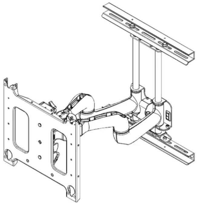
Large Flat Panel Dual Arm Wall Mount Model PNR™
The PNR is wall-mounted, rugged, versatile, and installer-friendly. The PNR is compatible with the standard (14" x 14") PSB interface bracket in which a display can be mounted in either the landscape or portrait position on the PNR.
The dual arms on the PNR:
Extend from the wall 25" in length
Pivot up to 90° left or right of center
The standard PNR is shipped with the support posts for the dual arms centered in the mount. The support posts can be moved laterally right or left of center to readily accommodate sites with limited wall space. The mount also has over an inch of height adjustment. The tilt range for the display is 5^ up and 15^ down.
The PNR was designed for fast installation. After drawing the plumb line and installing the two top lag bolts into the dual wall studs, the installer hangs the PNR on its top bracket and installs two lag bolts in the bottom bracket. Next, the installer makes the height adjustment, mounts the display, and connects the power/audio/video cables, which are diverted into the built-in path in the swing-out arms. After making the lateral, rotational, and tilt adjustments, the installation process is complete.
natural_image
Technical line drawing of a mechanical assembly with mounting brackets and structural components (no text or symbols)BEFORE YOU BEGIN
CAUTION: To prevent damage to the PNR, which could affect or void the Factory warranty, and to the equipment that will be attached to it, thoroughly study all instructions and illustrations before you begin the installation. Pay particular attention to the "Important Warnings and Cautions" on Page 2.
- The combined weight of the components installed on the PNR must not exceed 200 lbs. (90.72kg).
- The PNR wall mount must be installed on dual wall studs or supporting framework. The wall to which the PNR is anchored must be capable of supporting five times the total weight of the mount and all attached equipment.

IMPORTANT WARNINGS AND CAUTIONS!
WARNING: A WARNING alerts you to the possibility of serious injury or death if you do not follow the instructions.
CAUTION: A CAUTION alerts you to the possibility of damage or destruction of equipment if you do not follow the corresponding instructions.
WARNING: Improper installation can result in serious personal injury! Make sure that the structural members can support a redundant weight factor five times the total weight of the equipment: if not, reinforce the structure before installing the PNR.
WARNING: Be aware also of the potential for personal injury or damage to the unit if it is not adequately mounted.
WARNING: The installer is responsible for verifying that the wall to which the PNR is anchored will safely support the combined load of all attached components or other equipment.
WARNING: The weight of the display placed on the PNR must not exceed 200 lbs. (90.72kg), the maximum load capacity of the PNR.
WARNING: Watch for pinch points. Do not put your fingers between movable parts.
WARNING: Make sure the mount and brackets are correctly oriented.
WARNING: Make sure the flag securing the display is completely lowered at all times except when removing or installing the display.
CAUTION: Check the unit for shipping damage before you begin the installation.
Chief®, ClickConnect™ and Centris Select™ are registered trademarks of Milestone AV Technologies. All rights reserved.
CONTENTS
IMPORTANT WARNINGS AND CAUTIONS! 2
Inspect The Unit Before Installing 4
SPECIFICATIONS 4
INTERFACES 4
TOOLS REQUIRED FOR INSTALLATION ....4
PARTS LIST 4
INSTALLATION ....5
Install the Mount 5
Mounting the top bracket 5
Mounting the bottom bracket 5
Adjust Height on the PNR 6
Install Cover Plates and End Caps 6
Mount the Display 7
CABLE MANAGEMENT ....7
Adjustments 8
Removing Display from Mount 11
DIMENSIONAL DRAWING
Unit Depth
![Extended [635] 25.00](/content/2026/06/1185277/images/689d6ace4759a270c08c2d7da309e1c749ffda3337a4225a6389b963c26815a4.jpg)
![Retracted [88.90] 3.50 [687] 27.06](/content/2026/06/1185277/images/2c48f4aab47dc20b20f4be267c088a0b464f9aadb4b31843f8df7eff9d0e93cb.jpg)
Tilt Adjustment*
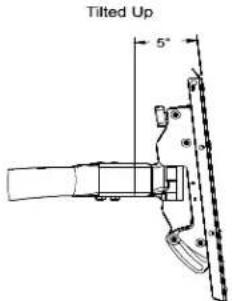
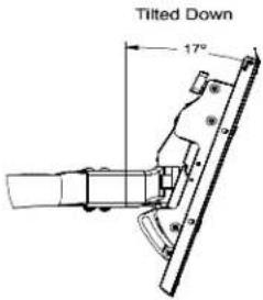
*The range of adjustment will vary with different size screens
![[67] 2.62](/content/2026/06/1185277/images/45b568dfb10572509f9529b1d130bd0a4052ebbe276512a1a538b370b3a0c87d.jpg)
Lowest Height Setting
Highest Height Setting
![[39] 1.55](/content/2026/06/1185277/images/ba271dc5c394cfeec5db396eaf9157bfa4ec9f314f18d9f620563af6eae02772.jpg)
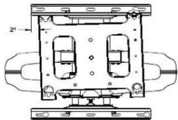
natural_image
Technical line drawing of a mechanical housing or enclosure with two internal compartments and mounting brackets (no text or symbols)Roll Adjustment
NOTE: CUSTOM INTERFACE BRACKET NOT SHOWN. THE CUSTOM INTERFACE BRACKET NEEDED FOR YOUR DISPLAY WILL ADD BETWEEN ½" AND 2" IN DEPTH AND MAY AFFECT LOCATION OF DISPLAY ON THE MOUNT.
MEASUREMENTS IN: [MILLIMETERS] INCHES
Inspect The Unit Before Installing
WARNING: Watch for pinch points. Do not put your fingers between movable parts.
- Carefully inspect the PNR for shipping damage. If any damage is apparent, call your carrier claims agent and do not continue with the installation until the carrier has reviewed the damage.
NOTE: Read all instructions before starting installation. - Lay out components to ensure you have all the required parts before proceeding. See "DIMENSIONAL DRAWING" on page 3.
SPECIFICATIONS
Table 1 provides the specifications for the mount.
Table 1: Mount Specifications
| Model Max Support Weight Mount | Extended from Wall |
| PNR 200 lbs. (90.72kg) 25"* |
NOTE: *Dimension does not include the PSB interface bracket.
INTERFACES
Table 2 lists the interface for the PNR.
Table 2: PNR Interfaces
| Model Interface | |
| PNR 14" x 14" Plasma Static Brackets (PSB) |
TOOLS REQUIRED FOR INSTALLATION
- Allen wrench set
- Drill and bit set
- Wrench set
NOTE: Other tools may be required depending on the method of installation.
PARTS LIST
Unpack the carton and verify the contents listed in Table 3.
Table 3: Parts List
| REF | DESCRIPTION | QTY |
| 10 | PNR Wall Mount | 1 |
| 20 | Cover Plates | 2 |
| 30 | End Caps | 4 |
| 40 | Tiewraps | 12 |
| 50 | Lag Bolts, 5/16" x 2-1/2" | 4 |
| 60 | Thick Washers, .850x.385x.135" | 4 |
| — | Wrench, Adjustment | 1 |
| — | Bar, Adjustment | 1 |
INSTALLATION

WARNING: Improper installation can result in serious personal injury!

WARNING: It is the responsibility of the installer to verify that the wall to which the PNR is anchored will safely support five times the combined load of all attached components and equipment. If not, reinforce the structure before installing the PNR.
- Locate two wood studs 16" apart on center
- Determine the exact mounting location prior to installation, considering screen size and the unit's total swing arm radius. Keep in mind that the PNR must be mounted to wood studs that are 16" apart on center.
NOTE: Mount the PNR between parallel wall studs or other supporting framework that is vertical or horizontal.
- Using a stud sensor, locate the two wood studs where you will mount the PNR.
-
Draw a level plumb line to indicate the desired height of the top mounting bracket.
-
With an assistant, lift and hold the PNR against wall. Use a pencil, awl, or small nail to mark the mounting holes where two pilot holes will be drilled into the center of the wood studs. Make sure the mounting holes are level.
-
With an assistant, lay the PNR down on the floor.
-
Drill two pilot holes using a 7/32" drill bit where the mounting holes were marked for anchoring the top bracket. See Figure 1.
-
Install two 5/16" x 2-1/2" lag bolts (50) and two 0.135" thick washers (60), through PNR Top Bracket and into upper pilot holes.
NOTE: Do not tighten the lag bolts down at this time. Leave enough space between the wall and lag bolts to hang the PNR.
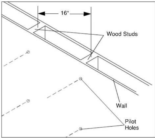
Figure 1
Install the Mount
Mounting the top bracket

WARNING: Improper installation can result in serious personal injury!
- With an assistant, lift and hang the PNR on the two lag bolts and washers previously installed on the wall. (See figure 2).
NOTE: Make sure washers are installed in front of the top bracket, not behind the bracket. - Slide the PNR into the desired position on the wall and tighten the two lag bolts.
Mounting the bottom bracket
- Mark the two mounting holes in the bottom mounting bracket (See figure 3). Make sure to align the holes parallel to the holes drilled in the top bracket.
- Drill two pilot holes in the wall studs using a 7/32" drill bit.
- Install two 5/16" x 2-1/2" lag bolts (50) and two 0.135" thick washers (60) through PNR Bottom Bracket into the lower pilot holes.
- Tighten all lag bolts.
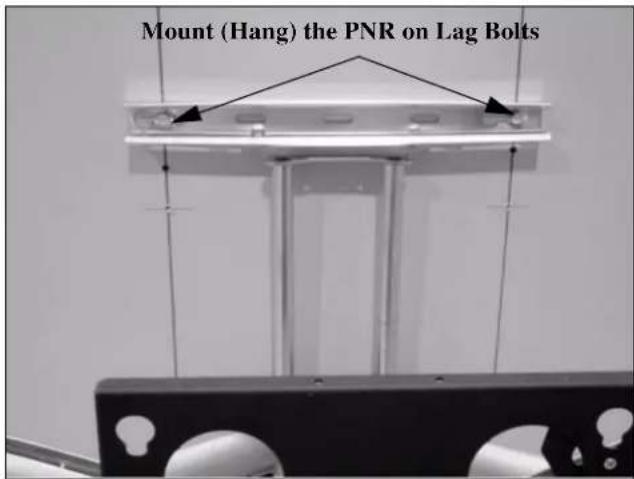
Figure 2
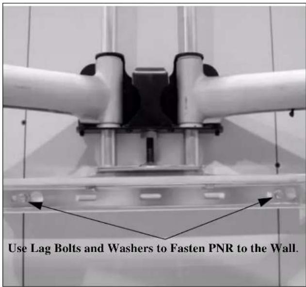
Figure 3
Adjust Height on the PNR
NOTE: Height adjustment range up to 1.08 inches.
To adjust the PNR height:
-
Check PNR for the desired height. If needed, use the adjustment wrench (40) to adjust the PNR height.
-
Turn adjustment nut (see Figure 4) clockwise (CW) to lower the unit height, or
- Turn adjustment nut counterclockwise (CCW) to raise the unit height.
Install Cover Plates and End Caps
NOTE: The cover plates and end caps have pressure fitting ends that lock in place with each other.
- Install cover plate (20) over the top bracket. (See figure 5)
- Install end cap (30) on the cover plate (20). (See figure 5)
- Repeat steps 1 and 2 for the bottom mounting bracket. (See figure 5)
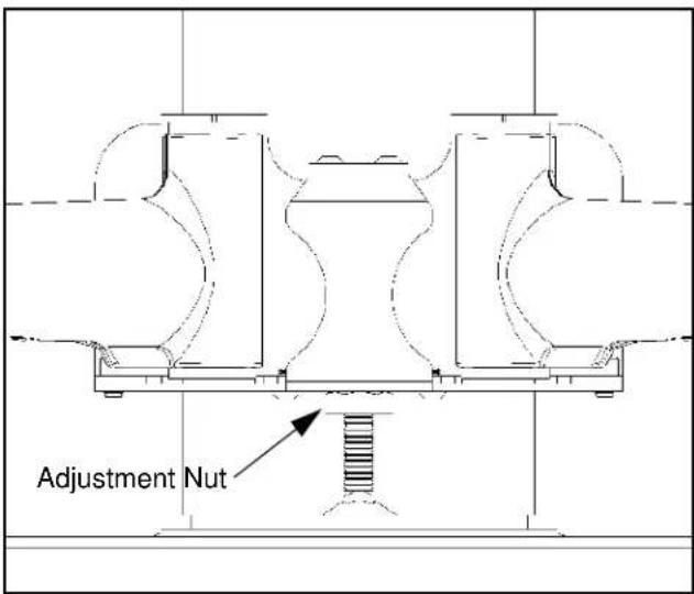
Figure 4
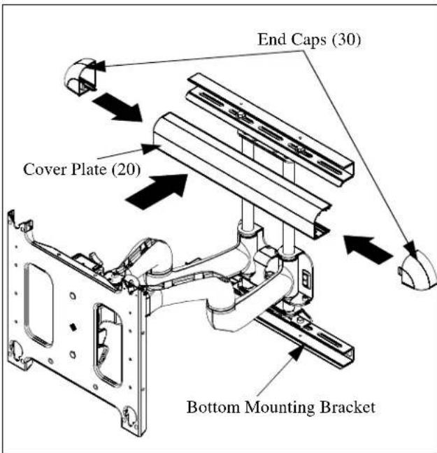
Figure 5
Mount the Display
- Make sure power is not supplied (turned off) to the display before attempting to mount the display.
- Following the instructions for mounting the PSB interface bracket of your specific plasma display panel, install the mounting bracket on your plasma display panel.

WARNING: Watch for pinch points. Do not put your fingers between movable parts.
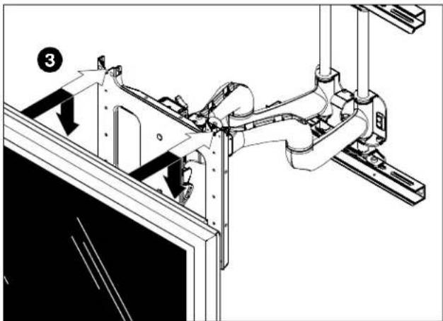
3. While supporting both sides of display, align four mounting buttons on display or interface bracket with four mounting holes in head assembly. (See Figures 6 and 7)
natural_image
Technical line drawing of a mechanical assembly with no visible text or symbolsFigure 6

WARNING: DISPLAY MAY WEIGH IN EXCESS OF 40 LBS! Always use two people and proper lifting techniques when installing or positioning display on stand.
- Lower display into place listening for audible "click" to ensure recessed area of mounting buttons are properly seated in lower area of mounting holes. (See Figures 6 and 7)

WARNING: IMPROPER INSTALLATION CAN LEAD TO DISPLAY FALLING CAUSING SERIOUS PERSONAL INJURY OR DAMAGE TO EQUIPMENT! Ensure mounting buttons are completely engaged in mounting holes.
NOTE: Holes are provided in the faceplate for use with a padlock or similar locking device, if desired. In addition, the pin and nut may be removed from the upper holes and moved to the lower holes for use as a more permanent locking device. (See Figure 7)
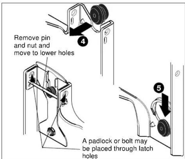
Figure 7
- Connect and secure power/audio/video cables, making sure to leave sufficient slack to allow for movement of the swing arms.
CABLE MANAGEMENT

WARNING: Make sure your cables do not run through a pinch point.
- Route power/audio/video cables through the cable channel in top arm (see Figure 8), allowing sufficient slack in cables for extension and avoiding pinch points, and secure cables using two clips and two tiewraps (40, not shown).
- Route power/audio/video cables along bottom arm (see Figure 9), using tiewraps (40, not shown) to secure cables to each arm, and through cable channel.

CAUTION: To prevent equipment damage, do not route cables through holes in the display mounting plate.
- Route power/audio/video cables to an open area behind the mounting plate (not shown). Leave a sufficient amount of slack in cables to allow for connection and extension where needed.
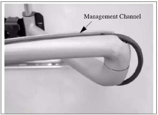
Figure 8
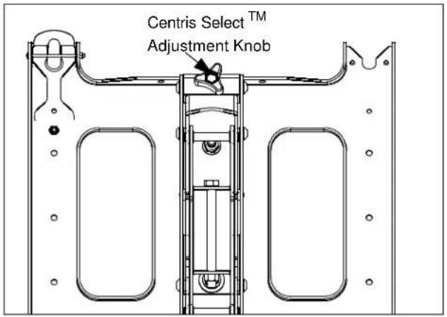
Figure 10
- To lock the mount at the desired vertical tilt, tighten the vertical tilt lock screw. (See figure 11)
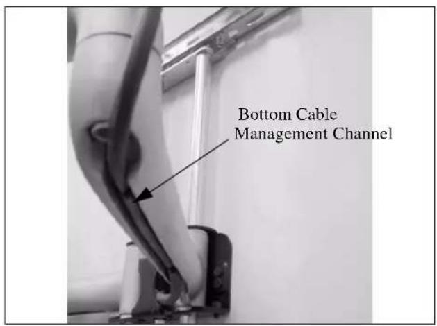
Figure 9
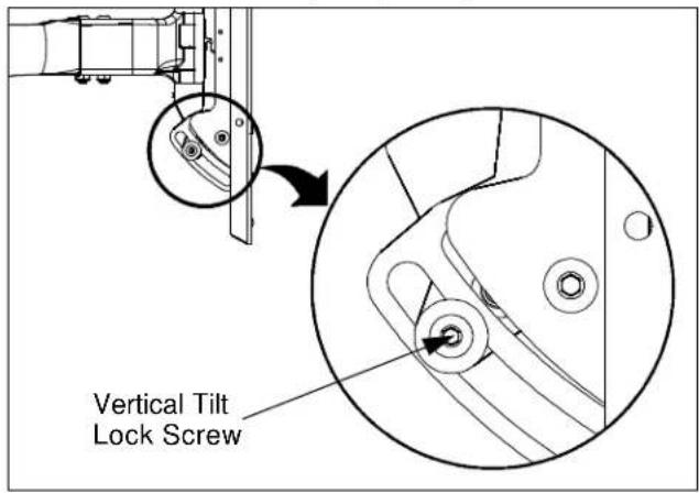
Figure 11
Lateral Tilt Tension Adjustment
ADJUSTMENTS
TENSION ADJUSTMENTS
Vertical Tilt Tension Adjustment
- With display mounted, check for desired vertical tilt tension.
- Adjust the Centris Select ^TM knob until desired vertical tilt tension is obtained. (See figure 10)

CAUTION: Overtightening lateral adjustment will cause excessive wear and may distort adjustment components.
- Using a 9/16" wrench (not provided), slightly tighten or loosen lateral tilt tension adjustment nut (See figure 12).
- Mount the display and check for desired tilt tension.
- Repeat Steps 1 and 2 until desired tilt tension is obtained.
Rotational Tilt Tension Adjustment
- If necessary, loosen or tighten bottom rotational tilt tension adjustment nut (See figure 12).
- Mount the display and check for desired rotational tilt tension.
- Repeat Steps 1 and 2 until desired rotational tilt tension is obtained.
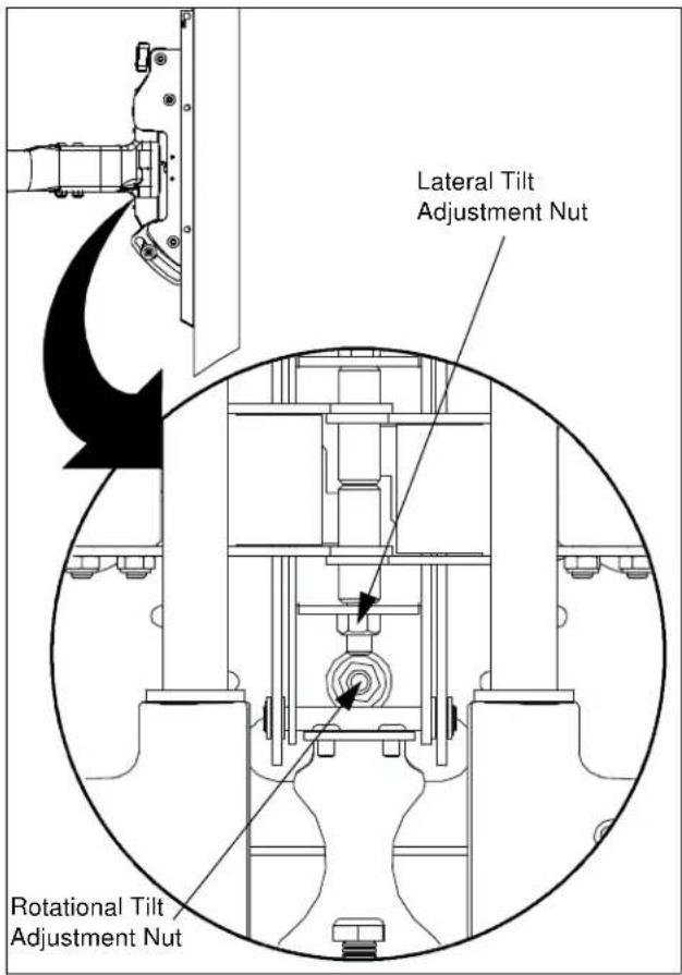
Figure 12
Swing Arm Adjustments
The dual swing arms are shipped installed in the center of the top and bottom mounting brackets, which is the standard mounting configuration.
The top and bottom mounting brackets have slotted holes, allowing for lateral adjustment of the dual swing arms.
After the top and bottom mounting brackets have been installed between two wood studs 16" on center, the swing arms can be adjusted or moved off center, depending on the location of the mount, the size of the display, and the lateral movement needed to rotate the display.
The swing arms can be adjusted, as follows:
- Adjusting the Swing Arms Off-Center
With no disassembly required, you can adjust the swing arms up to 1-inch to the left of center or up to 1-inch to the right of center.
- Reconfiguring the Swing Arms Left of Center
With some disassembly and reassembly required, you can move the swing arms to the left of center by reconfiguring the mount. Use the first and third slotted holes in the top and bottom mounting brackets.
• Reconfiguring the Swing Arms Right of Center
With some disassembly and reassembly, you can move the
swing arms to the right of center by reconfiguring the mount. Use the third and fifth slotted holes in the top and bottom mounting brackets.
Adjusting the Swing Arms Off Center
To adjust the dual swing arm mount configuration:
- Remove the display from the mount.
-
Loosen four bolts (two on the top and two on the bottom) securing the swing arm assembly to the top and bottom mounting brackets (See figure 13).
-
Move the swing arm assembly to desired location.
-
Tighten the bolts.
-
Install the display on the mount.
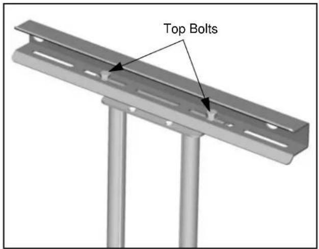
Figure 13
Reconfiguring the Swing Arms to the Left or Right of Center
To change of the dual swing arm mount configuration:
-
Remove the display from the mount.
-
Remove four bolts (two on the top and two on the bottom) securing the swing arm assembly to the top and bottom mounting brackets (See figure 14).

WARNING: The next step will release the arm assembly from the mount. The arms and plate may fall if you are not careful.
-
Move the swing arm assembly to desired location.
-
For Left of Center, see Figure 14.
-
For Right of Center, see Figure 15.
-
Install retaining pin assemblies (one top and one bottom) and secure using two bolts (one top and one bottom).
- Install four bolts (two on the top and two on the bottom) to secure the swing arm assembly to the top and bottom mounting brackets (See figure 14).
- Tighten the bolts.
- Install the display on the mount.
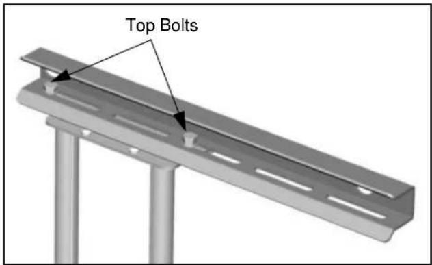
Figure 14
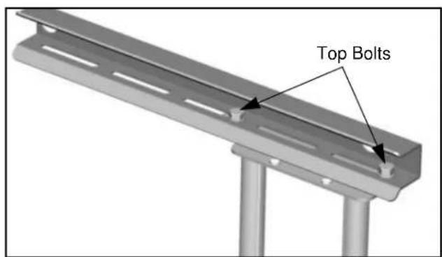
Figure 15
Swing Arm Tension Adjustment
Swing arm tension is pre-set at the factory and is adjusted to accommodate displays with weights near the top of the mounts capacity.
If smaller displays are used it may be difficult to reposition the display after mounting. Swing arm tension can be adjusted to compensate for smaller display by:
NOTE: The display must be mounted prior to adjusting swing arm tension.
- Locate the adjustment bar and wrench provided with the mount.
- Place adjustment bar into socket head cap screw located at swing arm pivot point. (See figure 16)
NOTE: The display may need to be repositioned in order to gain access to the tension adjustment screw(s).
- Using the wrench provided with the mount, turn adjustment bar clockwise to increase swing arm tension or counterclockwise to reduce swing arm tension. (See figure 17) and (See figure 18)
NOTE: Small adjustments of 1/8 turn or less are typically all that is required to achieve desired tension.
- Check swing arm tension. If desired tension is present, tension adjustment is complete. If additional tension adjustment is required, repeat steps 2 and 3 until desired tension is achieved.
NOTE: If changing from a smaller display to a larger display it may be necessary to increase swing arm tension.

Figure 16
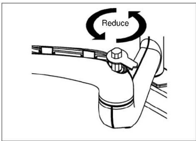
Figure 17
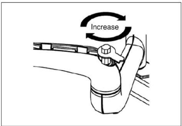
Figure 18
Removing Display from Mount
- Remove bolt or padlock from faceplate (if used).
NOTE: The pin may have been used as a more permanent locking device. If so, remove nut and pin and move from the lower holes to the upper holes.
- Pull back on flag on upper mounting hole and press pin down into "Open" position. (See Figure 19)

WARNING: DISPLAY MAY WEIGH IN EXCESS OF 40 LBS! Always use two people and proper lifting techniques when installing or positioning display on mount.
-
Carefully lift display from mount.
-
Lift up on pin and place flag back against faceplate to return it to "Closed" position.
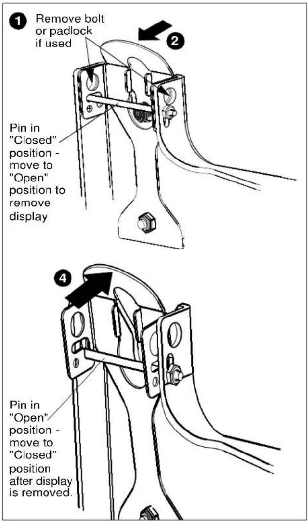
Figure 19