KTC220B - TV wall mount Chief - Free user manual and instructions
Find the device manual for free KTC220B Chief in PDF.

User questions about KTC220B Chief
0 question about this device. Answer the ones you know or ask your own.
Ask a new question about this device
Download the instructions for your TV wall mount in PDF format for free! Find your manual KTC220B - Chief and take your electronic device back in hand. On this page are published all the documents necessary for the use of your device. KTC220B by Chief.
USER MANUAL KTC220B Chief
INSTALLATION INSTRUCTIONS
KTC-220
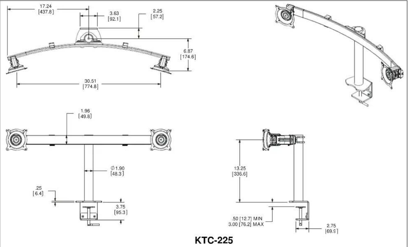
KTC-225
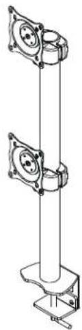
KTC-230
natural_image
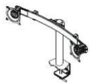
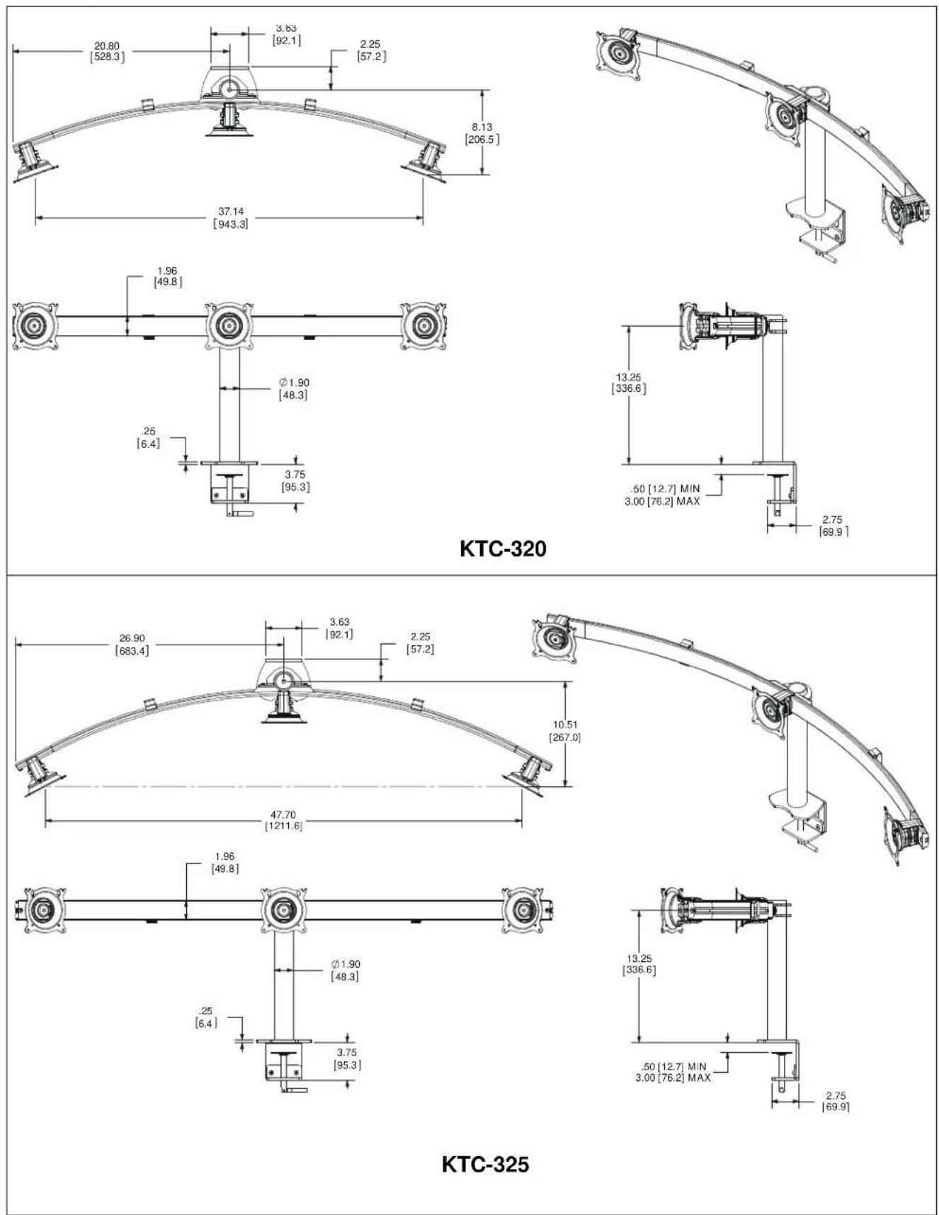
Mechanical linkage assembly diagram with articulated arms and mounting base (no text or symbols)KTC-320

natural_image
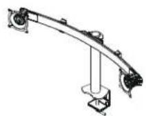
Mechanical linkage assembly diagram showing curved and articulated components (no text or symbols)KTC-325
natural_image
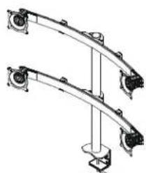
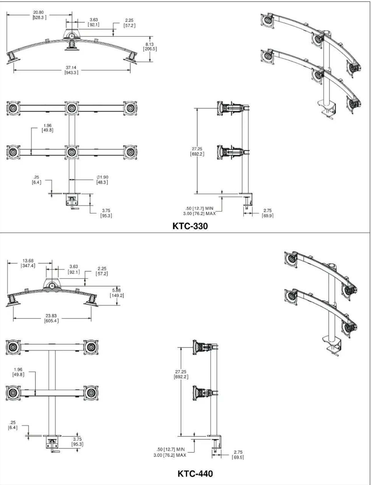
Mechanical assembly diagram showing two curved mechanical components with mounting brackets (no text or symbols)KTC-330
natural_image
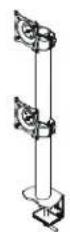
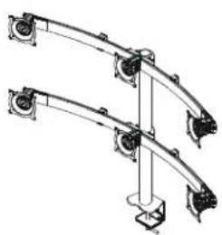
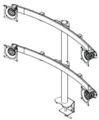
Mechanical assembly diagram showing two articulated arms connected by a vertical rod (no text or symbols)KTC-440
natural_image
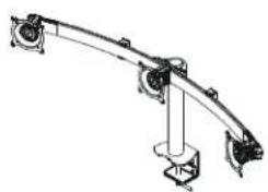
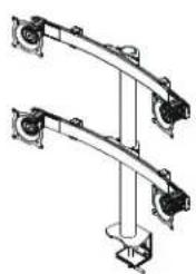
Mechanical assembly diagram showing two curved components mounted on a vertical support (no text or symbols)KTC-445
Horizontal and Vertical Desk Clamp Stands
DISCLAIMER
Milestone AV Technologies and its affiliated corporations and subsidiaries (collectively "Milestone"), intend to make this manual accurate and complete. However, Milestone makes no claim that the information contained herein covers all details, conditions or variations, nor does it provide for every possible contingency in connection with the installation or use of this product. The information contained in this document is subject to change without notice or obligation of any kind. Milestone makes no representation of warranty, expressed or implied, regarding the information contained herein. Milestone assumes no responsibility for accuracy, completeness or sufficiency of the information contained in this document.
Chief® and Centris™ are registered trademarks of Milestone AV Technologies. All rights reserved.

IMPORTANT WARNINGS AND TIONS!

WARNING: A WARNING alerts you to the possibility of serious injury or death if you do not follow the instructions.

CAUTION: A CAUTION alerts you to the possibility of damage or destruction of equipment if you do not follow the corresponding instructions.

WARNING: Failure to read, thoroughly understand, and follow all instructions can result in serious personal injury, damage to equipment, or voiding of factory warranty! It is the installer's responsibility to make sure all components are properly assembled and installed using the instructions provided.

WARNING: Failure to provide adequate structural strength for this component can result in serious personal injury or damage to equipment! It is the installer's responsibility to make sure the structure to which this component is attached can support five times the combined weight of all equipment. Reinforce the structure as required before installing the component.

WARNING: Failure to keep all mounted equipment directly above the desk surface at all times can result in serious personal injury or damage to equipment! All mounted equipment must remain directly above the surface of the desk in order to ensure and maintain a stable mount.

WARNING: Exceeding the weight capacity can result in serious personal injury or damage to equipment! It is the installer's responsibility to make sure the weight of each monitor attached does not exceed the weight limit for each specific model. Refer to Table 1 for the weight limits for each model.
DIMENSIONS
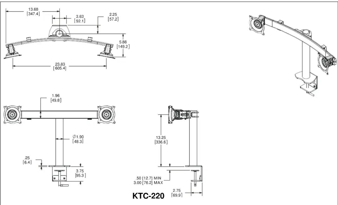
DIMENSIONS - CONTINUED
![3.26 [82.7] 3.63 [92.1] 5.50 [139.6] 2.25 [57.2]](/content/2026/06/1184091/images/b1a23597604753ddda98e618f1835f3c6befc985144aa55c4ddf16eaf6267358.jpg)
![Ø1.90 .25 3.75 [95.3]](/content/2026/06/1184091/images/9978946e50cf6316aace474d3508b196ef198968c737b0fc9c1f95179aaadd6b.jpg)
![29.75 [755.6] .50 [12.7] MIN 3.00 [76.2] MAX 2.75 [69.9]](/content/2026/06/1184091/images/56ebee08c7adc91c5408e23c181faccfef45227bca8893a512b837f75a7792ba.jpg)
KTC-230
natural_image
Technical line drawing of a vertical cylindrical device with two circular components mounted on a base (no text or symbols)DIMENSIONS - CONTINUED
DIMENSIONS - CONTINUED
DIMENSIONS - CONTINUED
![17.24 [437.8] 3.63 [92.1] 2.25 [57.2] 6.87 [174.6] 30.51 [774.8]](/content/2026/06/1184091/images/9902eb3ed1babefaecc522e41bbff98d8a4f3e7b34d07d5c7e4f506a6492b550.jpg)
![1.96 [49.8] .25 [6.4] 3.75 [95.3]](/content/2026/06/1184091/images/78c8a7628050a14cb3c5048169d547c0697aeb5921d5a2ee842207ad2d7fc407.jpg)
KTC-445
![27.25 [692.2] .50 [12.7] MIN 3.00 [76.2] MAX 2.75 [69.9]](/content/2026/06/1184091/images/4ab2e337abc659e04fd67c7e5238a45b0c1c9327aeba32d309c1385343ddd7ad.jpg)
natural_image
Technical line drawing of two curved mechanical components mounted on a vertical support (no text or symbols)LEGEND
 | Tighten Fastener |
| Apretar elemento de fijación | |
| Befestigungsteil festziehen | |
| Apertar fixador | |
| Serrare il fissaggio | |
| Bevestiging vastdraaien | |
| Serrez les fixations | |
 | Loosen Fastener |
| Aflojar elemento de fijación | |
| Befestigungsteil lösen | |
| Desapertar fixador | |
| Allentare il fissaggio | |
| Bevestiging losdraaien | |
| Desserrez les fixations | |
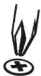 | Phillips Screwdriver |
| Destornillador Phillips | |
| Kreuzschlitzschraubendreher | |
| Chave de fendas Phillips | |
| Cacciavite a stella | |
| Kruiskopschroevendraaier | |
| Tournevis à pointe cruciforme | |
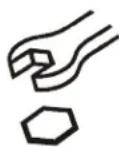 | Open-Ended Wrench |
| Llave de boca | |
| Gabelschlüssel | |
| Chave de bocas | |
| Chiave a punte aperte | |
| Steeksleutel | |
| Clé à fourche | |
 | By Hand |
| A mano | |
| Von Hand | |
| Com a mão | |
| A mano | |
| Met de hand | |
| À la main | |
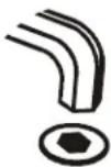 | Hex-Head Wrench |
| Llave de cabeza hexagonal | |
| Sechskantschlüssel | |
| Chave de cabeça sextavada | |
| Chiave esagonale | |
| Zeskantsleutel | |
| Clé à tête hexagonale |


Pencil Mark
Marcar con lápiz
Stiftmarkierung
Marcar com lápis
Segno a matita
Potloodmerkteken
Marquage au crayon
Drill Hole
Perforar
Bohrloch
Fazer furo
Praticare un foro
Gat boren
Percez un trou
Adjust
Ajustar
Einstellen
Ajustar
Regolare
Afstellen
Ajuster
Remove
Quitar
Entfernen
Remover
Rimuovere
Verwijderen
Retirez
Optional
Opcional
Optional
Opcional
Opzionale
Optie
En option
Security Wrench
Llave de seguridad
Sicherheitsschlüssel
Chave de segurança
Chiave di sicurezza
Veiligheidssleutel
Clé de sécurité
Table 1: Monitor Limits
| MONITOR LIMITS By MODEL | |||||||||
| DESCRIPTION | 220 | 225 | 230 | 320 | 325 | 330 | 440 | 445 | |
| Weight | 35 lbs | 35 lbs | 35 lbs | 30 lbs | 30 lbs. | 20 lbs | 30 lbs | 30 lbs | |
| Max Screen Width | 22.7" | 30" | N/A | 18" | 24.5" | 18" | 22.7" | 30" | |
| Max Screen Height | 28" | 28" | 19.3" | 28" | 28" | 18.5" | 18.5" | 18.5" | |
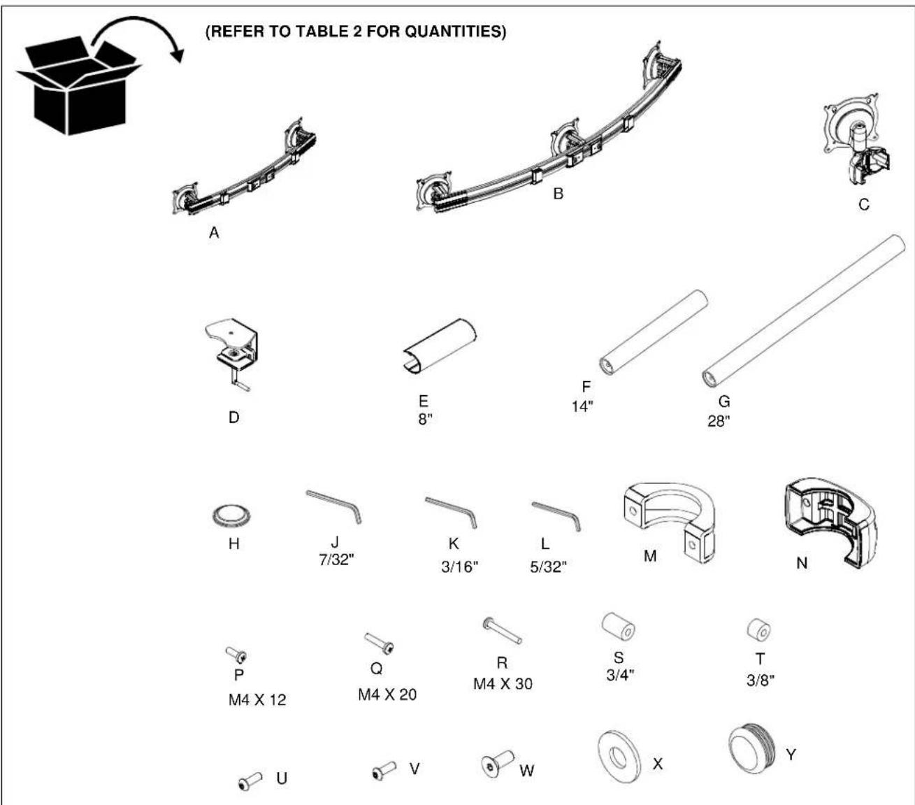
Table 2: Parts
| QUANTITY By MODEL | |||||||||
| ITEM | DESCRIPTION | 220 | 225 | 230 | 320 | 325 | 330 | 440 | 445 |
| A ARR | AY ASSEMBLY, Dual, 27" 1 2 | ||||||||
| ARRAY ASSEMBLY, Dual, 34" 1 2 | |||||||||
| B ARR | AY ASSEMBLY, Triple, 42" 1 2 | ||||||||
| ARRAY ASSEMBLY, Triple, 54" | 1 | ||||||||
| C | CENTRIS HEAD ASSEMBLY, Pole Mount | 2 | |||||||
| D | DESK CLAMP | 1 | 1 | 1 | 1 | 1 | 1 | 1 | 1 |
| E | SHEATH, Cable Management, 8" | 1 | 1 | 2 | 1 | 1 | 2 | 2 | 2 |
| F | POLE, Mount Freestanding, 14" | 1 | 1 | 1 | 1 | ||||
| G | POLE, Mount Freestanding, 28" | 1 | 1 | 1 | 1 | ||||
| H | BUMPER, | 6 | 6 | 6 | 6 | 6 | 6 | 6 | 6 |
| J | KEY, Hex, 5/32" | 1 | 1 | 1 | 1 | 6 | 1 | 1 | 1 |
| K KEY | Hex, 3/16" | 1 | |||||||
| L | KEY, Hex, 7/32" | 1 | 1 | 1 | 1 | 1 | 1 | 1 | 1 |
| M | CLAMP, Pole 2" Pipe | 1 | 1 | 1 | 1 | 2 | 2 | 2 | |
| N | CLAMP, Back Casting | 2 | |||||||
| P | SCREW, Phillips Pan Head, M4 x 12mm | 8 | 8 | 8 | 12 | 12 | 24 | 16 | 16 |
| Q | SCREW, Phillips Pan Head, M4 x 20mm | 8 | 8 | 8 | 12 | 12 | 24 | 16 | 16 |
| R | SCREW, Phillips Pan Head, M4 x 30mm | 8 | 8 | 8 | 12 | 12 | 24 | 16 | 16 |
| S | SPACER, Nylon, 3/8" (used with item Q) | 8 | 8 | 8 | 12 | 12 | 24 | 16 | 16 |
| T | SPACER, Nylon, 3/4" (used with item R) | 8 | 8 | 8 | 12 | 12 | 24 | 16 | 16 |
| U | SCREW, Button Head Cap, 1/4-20 x 3/4" | 2 | 2 | 2 | 2 | 4 | 4 | 4 | |
| V | SCREW, Button Head Cap, 1/4-20 x 1 1/4" | 6 | |||||||
| W | SCREW, Flat Head Cap, 3/8-16 x 1" | 1 | 1 | 1 | 1 | 1 | 1 | 1 | 1 |
| X | WASHER, Flat, 1/4" | 2 | 2 | 2 | 2 | 4 | 4 | 4 | |
| Y | PIPE CAP, 1.75 OD | 1 | 1 | 1 | 1 | 1 | 1 | 1 | 1 |
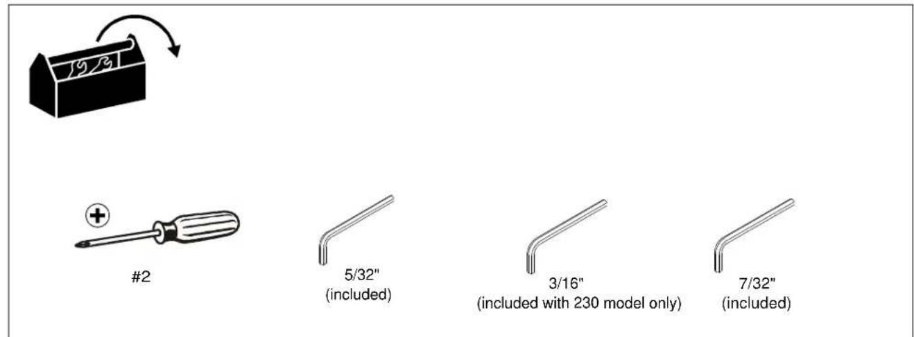
TOOLS REQUIRED FOR INSTALLATION
PARTS
INSTALLATION
Desk Clamp Installation
NOTE: In order to reduce the chance of scratching to the mounting surface, bumpers may be installed. However, installation of bumpers is optional.
- Remove adhesive from underside of bumpers (H).
- Attach bumpers (H) to underside of desk clamp (D). (See Figure 1)
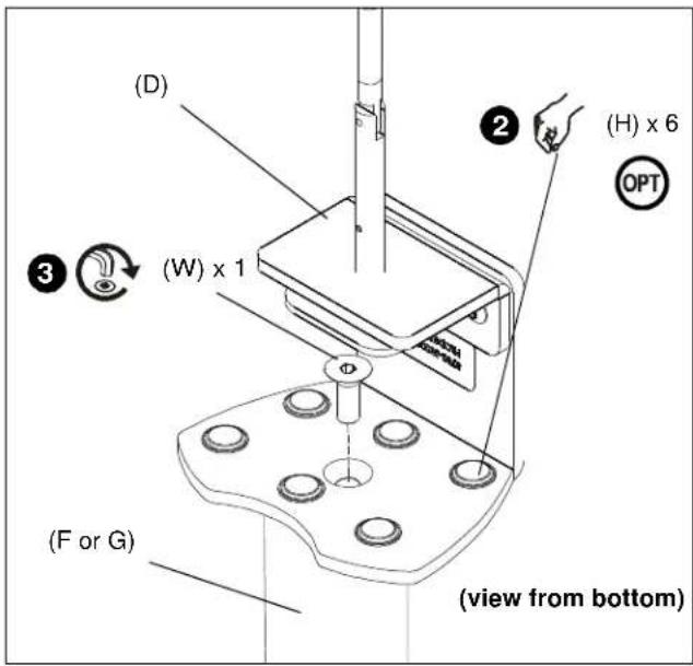
Figure 1
-
Use 7/32" hex key (J) to install 3/8-16 x 1" flat head cap screw (W) through the opening on top of desk clamp (D) and into bottom of mounting pole (F or G). (See Figure 1)
-
Determine the location where desk clamp will be mounted.

WARNING: Failure to keep all mounted equipment directly above the desk surface at all times can result in serious personal injury or damage to equipment! All mounted equipment must remain directly above the surface of the desk in order to ensure and maintain a stable mount.
-
Place desk clamp (D) over desired mounting location on desk. (See Figure 2)
-
If there is not enough clearance behind the desk for the device to clear, remove the bottom portion of the desk clamp by using 5/32" hex key (L) to remove 2 connecting screws. (See Figure 2)
-
Reinstall bottom portion of the desk clamp (if necessary) by reinstalling 2 connecting screws underneath desk. (See Figure 2)
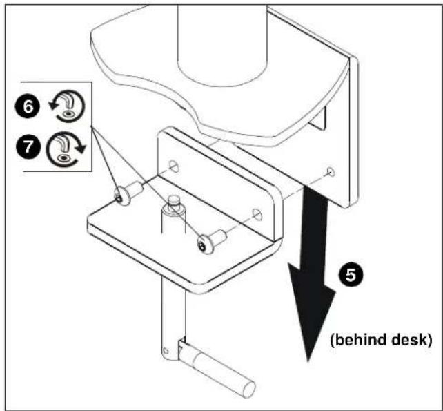
Figure 2
- Turn clamp screw until the clamp is secured to the desk as tightly as possible. (See Figure 3)
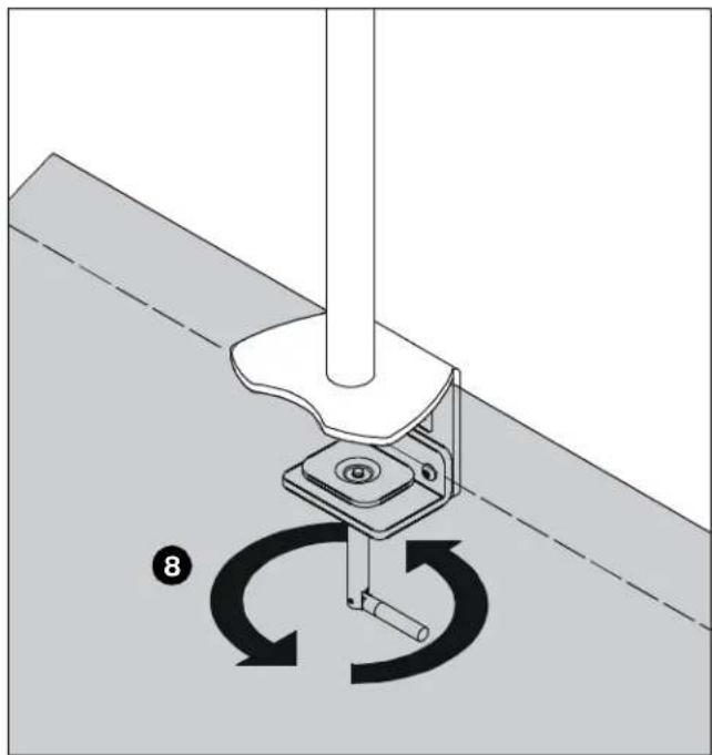
natural_image
Mechanical assembly diagram showing a rotating component with circular motion arrows (no text or symbols)Figure 3
Mount Assembly
KTC-230 Assembly
- Place front pole clamp with Centris Head (C) against pole (G) in approximate mounting location.
- Place three 1/4-20 X 1 1/4" button head cap screws (V) into rear pole clamp (N) and place against pole aligning with front pole clamp on Centris Head (C). (See Figure 4)
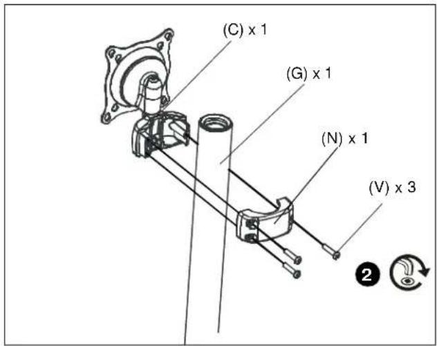
Figure 4
- Equally tighten screws (V) against front pole mount and the rear pole clamp (N). (See Figure 5)
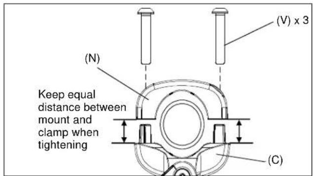
Figure 5
- Secure rear pole clamp (N) to Centris head's front pole mount (C) and pole (G) by tightening three button head cap screws (V) using 5/32" hex key (J). (See Figure 4)
- Repeat steps 1-4 for additional Centris head.
- Add pipe cap (Y) to top of pole (F or G).
KTC-220, 225, 320, 325, 330, 440 and 445 Assembly
- Assemble pole clamp back (M) to pole mount front using two washers (X) and two 1/4-20 x 3/4" button head cap screws (U) using a 5/32" hex key (J). (See Figure 6)
- Secure pole mount back (M) to pole mount front and pole by tightening two button head cap screws (U) using a 5/32" hex key (J).
- Repeat steps 1-2 for additional array mount on KTC-330, 440 and 445.
- Add pipe cap (Y) to top of pole (F or G).
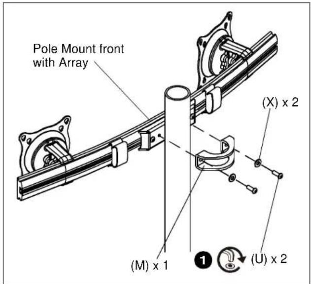
Figure 6
Display Installation
Attach Centris Head to Flush Mount Display

CAUTION: If display uses a screw size other than those included in the kit, DO NOT use the screws provided. Using the wrong screws could result in damage to your monitor.
- Install two M4 x 12mm Phillips pan head screws (P) into two upper mounting holes in display back using #2 Phillips screwdriver. (See Figure 7)
NOTE: DO NOT fully tighten at this time.
- Hang display on Centris head. (See Figure 8)
- Install bottom two M4 x 12mm Phillips pan head screws (P) through Centris head mounting holes and into lower mounting holes in display back.
- Tighten ALL four M4 x 12mm Phillips pan head screws (P). (See Figure 9)
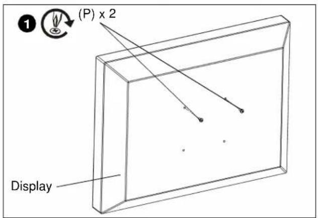
Figure 7
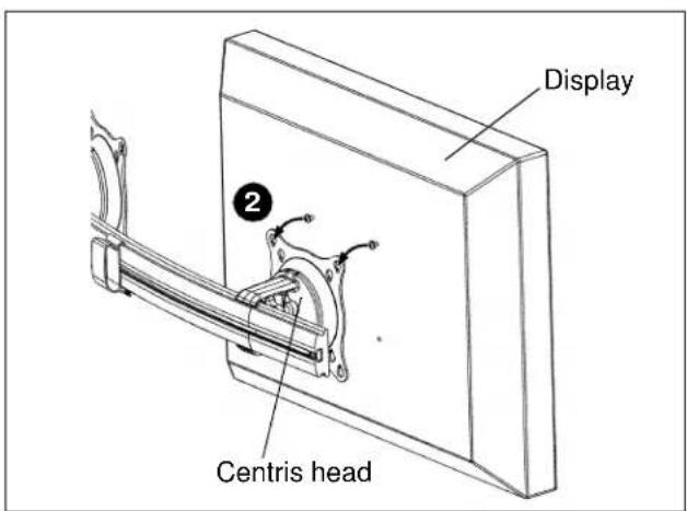
Figure 8
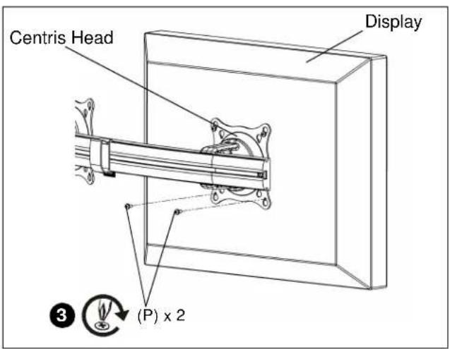
Figure 9
Attach Centris Head to Recessed Mount Display
NOTE: Refer to Table 1 to select the applicable screw and spacer combination.
- Uninstall end lock using the 5/32" hex key (J). (See Figure 10)
- Slide Centris head off array rail. (See Figure 11)
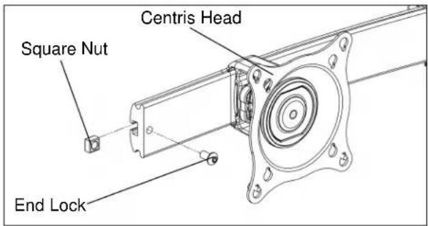
Figure 10
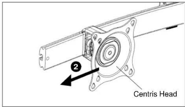
Figure 11
- Place display face down on a clean dry surface.
- Place four 3/8" or 3/4" nylon spacers (S or T) over four mounting holes in display back (See Figure 12).
- Align Centris head mounting holes with four nylon spacers (See Figure 12).
- Secure Centris head to display using four M4 x 20mm Phillips pan head screws (Q), or four M4 x 30mm Phillips pan head screws (R). (See Figure 12).
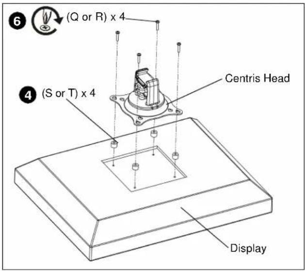
Figure 12
- Slide display with Centris bracket onto array rail. (See Figure 13)
NOTE: Repeat previous steps for each additional display.
- Reinstall end locks into mounting rail using the 5/32" hex key (J) (See Figure 14).
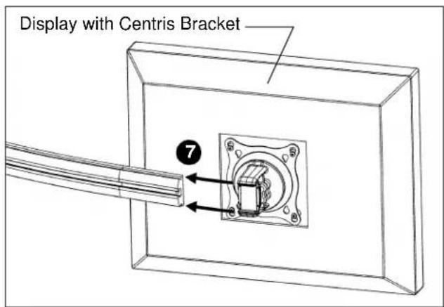
Figure 13
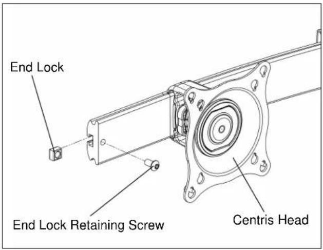
Figure 14
ADJUSTMENTS
Display Adjustment
The KTC Series mount allows horizontal, pitch, and rotational adjustment of each display.
The KTC Series mount also allows a full 360 deg. of display rotation with a maximum pitch range of 15^ up and 15^ down.
The 3/16" hex key included with the KTC-230 mount is to be used to adjust the rotation on this model.
Display Horizontal Position Adjustment
To adjust display horizontal position:
- Loosen Centris bracket rear adjustment knob (See Figure 15).
- Slide Centris bracket with display left or right until properly positioned on array rail.
- Tighten Centris bracket rear adjustment knob.
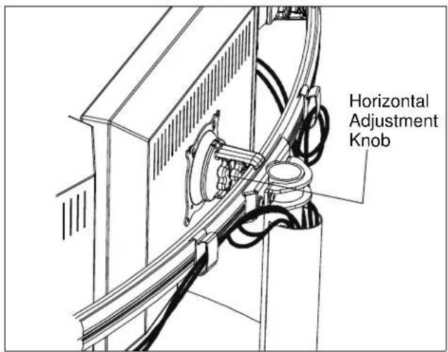
Figure 15
Display Pitch and Roll Adjustment
To adjust display pitch or roll position:
- Loosen Centris bracket front adjustment knob. (See Figure 16)
- Tilt display up or down, or adjust display roll left or right until properly positioned.
- Tighten Centris bracket front adjustment knob.
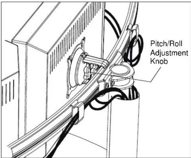
Figure 16
CABLE MANAGEMENT
The KTC Series mount includes cable management features used to properly route and secure display cables.
To use the cable management features:
- Connect cables to display.
- Route cables through cable clips on array rail. (See Figure 17)
- Route cables down pole and away from mount and secure to pole using sheath (E). (See Figure 17)
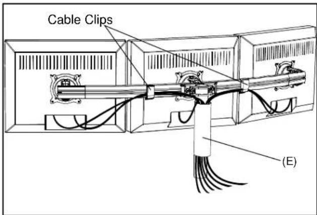
Figure 17
- Repeat steps 1-3 for additional array on KTC-330, 440 and 445.
KTC SERIES
Installation Instructions