QSDWT4-70NA5 - Security Camera Moog Videolarm - Free user manual and instructions
Find the device manual for free QSDWT4-70NA5 Moog Videolarm in PDF.

User questions about QSDWT4-70NA5 Moog Videolarm
0 question about this device. Answer the ones you know or ask your own.
Ask a new question about this device
Download the instructions for your Security Camera in PDF format for free! Find your manual QSDWT4-70NA5 - Moog Videolarm and take your electronic device back in hand. On this page are published all the documents necessary for the use of your device. QSDWT4-70NA5 by Moog Videolarm.
USER MANUAL QSDWT4-70NA5 Moog Videolarm
© 2009, Videolarm, Inc. All Rights Reserved
natural_image
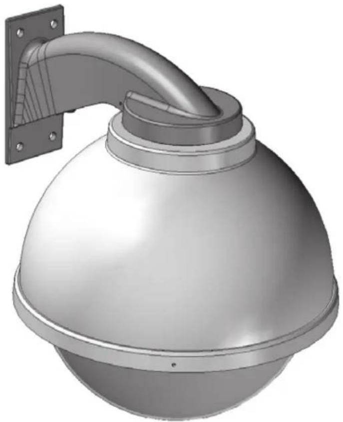
3D rendering of a spherical security camera with a curved pipe mounted on top, mounted on a wall (no text or symbols visible)QSDW and QSDP
QView Series QSD Outdoor Dome
www.videolarm.com
Installation and Operation Instructions for the following models:

CERTIFIED
© 2009. Videolarm. Inc. All Rights Reserved
Before attempting to connect or operate this product, please read these instructions completely.
81-IN5362
02-03-2009
- Read Instructions - All the safety and operating instructions should be read before the unit is operated.
- Retain Instructions - The safety and operating instructions should be retained for future reference.
- Heed Warnings - All warnings on the unit and in the operating instructions should be adhered to.
- Follow Instructions - All operating & user instructions should be followed.
- Electrical Connections - Only a qualified electrician should make electrical connections.
- Attachments - Do not use attachments not recommended by the product manufacturer as they may cause hazards.
- Cable Runs - All cable runs must be within permissible distance.
- Mounting - This unit must be properly and securely mounted to a supporting structure capable of sustaining the weight of the unit. Accordingly:
a. Installation should be made by a qualified installer.
b. Installation should be in compliance with local codes.
c. Care should be exercised to select suitable hardware to install the unit, taking into account both the composition of the mounting surface and the weight of the unit. Be sure to periodically examine the unit and the supporting structure to make sure that the integrity of the installation is intact. Failure to comply with the foregoing could result in the unit separating from the support structure and falling, with resultant damages or injury to anyone or anything struck by the falling unit.
UNPACKING
Unpack carefully. Electronic components can be damaged if improperly handled or dropped. If an item appears to have been damaged in shipment, replace it properly in its carton and notify the shipper. Be sure to save:
- The shipping carton and packaging material. They are the safest material in which to make future shipments of the equipment.
- These Installation and Operating Instructions.
SAFETY PRECAUTIONS IMPORTANT SAFEGUARDS


CAUTION: TO REDUCE THE RISK OF ELECTRICAL SHOCK, DO NOT EXPOSE COMPONENTS TO WATER OR MOISTURE.
The lightning flash with an arrowhead symbol, within an equilateral triangle, is intended to alert the user to the presence of non-insulated "dangerous voltage" within the product's enclosure that may be of sufficient magnitude to constitute a risk of electric shock to persons.

The exclamation point within an equilateral triangle is intended to alert the user to presence of important operating and maintenance (servicing) instructions in the literature accompanying the appliance.
SERVICE
If the unit ever needs repair service, customer should contact Videolarm (1-800-554-1124) for return authorization & shipping instructions.
TECHNICAL SUPPORT
Videolarm has set-up a 24 hour technical support line for their customers.
24 HOUR TECHNICAL SUPPORT
1-800-554-1124
LIMITED WARRANTY FOR VIDEOLARM INC. PRODUCTS
VIDEOLARM INC. warrants this Product to be free from defects in material or workmanship, as follows:
PRODUCT CATEGORY
| All Enclosures and Electronics | Five (5) Years | Five (5) Years | ||
| Pan/Tilts | Three (3) Years | **6 months if used in autoscan | Three (3) Years | **6 months if used in autoscan |
| Poles/PoleEvators | Three (3) Years | / tour operation | Three (3) Years | / tour operation |
| Warrior/Q-View/I.R. Illuminators | Five (5) Years | Five (5) Years | ||
| SView Series | Five (5) Years | **6 months if used in autoscan | Five (5) Years | **6 months if used in autoscan |
| Controllers | Five (5) Years | / tour operation | Five (5) Years | / tour operation |
| Power Supplies | Five (5) Years | Five (5) Years | ||
| Accessory Brackets | Five (5) Years | Five (5) Years |
During the labor warranty period, to repair the Product, Purchaser will either return the defective product, freight prepaid, or deliver it to Videolarm Inc. Decatur GA. The Product to be repaired is to be returned in either its original carton or a similar package affording an equal degree of protection with a RMA # (Return Materials Authorization number) displayed on the outer box or packing slip. To obtain a RMA# you must contact our Technical Support Team at 800.554.1124, extension 101. Videolarm will return the repaired Product freight prepaid to Purchaser. Videolarm is not obligated to provide Purchaser with a substitute unit during the warranty period or at any time. After the applicable warranty period, Purchaser must pay all labor and/or parts charges.
The limited warranty stated in these product instructions is subject to all of the following terms and conditions:
-
NOTIFICATION OF CLAIMS: WARRANTY SERVICE: If Purchaser believes that the Product is defective in material or workmanship, then written notice with an explanation of the claim shall be given promptly by Purchaser to Videolarm but all claims for warranty service must be made within the warranty period. If after investigation Videolarm determines that the reported problem was not covered by the warranty, Purchaser shall pay Videolarm for the cost of investigating the problem at its then prevailing per incident billable rate. No repair or replacement of any Product or part thereof shall extend the warranty period as to the entire Product. The specific warranty on the repaired part only shall be in effect for a period of ninety (90) days following the repair or replacement of that part or the remaining period of the Product parts warranty, whichever is greater.
-
EXCLUSIVE REMEDY: ACCEPTANCE: Purchaser's exclusive remedy and Videolarm's sole obligation is to supply (or pay for) all labor necessary to repair any Product found to be defective within the warranty period and to supply, at no extra charge, new or rebuilt replacements for defective parts.
-
EXCEPTIONS TO LIMITED WARRANTY: Videolarm shall have no liability or obligation to Purchaser with respect to any Product requiring service during the warranty period which is subjected to any of the following: abuse, improper use: negligence, accident, lightning damage or other acts of God (i.e., hurricanes, earthquakes), modification, failure of the end-user to follow the directions outlined in the product instructions, failure of the end-user to follow the maintenance procedures recommended by the International Security Industry Organization, written in product instructions, or recommended in the service manual for the Product. Furthermore, Videolarm shall have no liability where a schedule is specified for regular replacement or maintenance or cleaning of certain parts (based on usage) and the end-user has failed to follow such schedule; attempted repair by non-qualified personnel; operation of the Product outside of the published environmental and electrical parameters, or if such Product's original identification (trademark, serial number) markings have been defaced, altered, or removed. Videolarm excludes from warranty coverage Products sold AS IS and/or WITH ALL FAULTS and excludes used Products which have not been sold by Videolarm to the Purchaser. All software and accompanying documentation furnished with, or as part of the Product is furnished "AS IS" (i.e., without any warranty of any kind), except where expressly provided otherwise in any documentation or license agreement furnished with the Product.
-
PROOF OF PURCHASE: The Purchaser's dated bill of sale must be retained as evidence of the date of purchase and to establish warranty eligibility. DISCLAIMER OF WARRANTY EXCEPT FOR THE FOREGOING WARRANTIES, VIDEOLARM HEREBY DISCLAIMS AND EXCLUDES ALL OTHER WARRANTIES, EXPRESS OR IMPLIED, INCLUDING, BUT NOT LIMITED TO ANY AND/OR ALL IMPLIED WARRANTIES OF MERCHANTABILITY, FITNESS FOR A PARTICULAR PURPOSE AND/OR ANY WARRANTY WITH REGARD TO ANY CLAIM OF INFRINGEMENT THAT MAY BE PROVIDED IN SECTION 2-312(3) OF THE UNIFORM COMMERCIAL CODE AND/OR IN ANY OTHER COMPARABLE STATE STATUTE. VIDEOLARM HEREBY DISCLAIMS ANY REPRESENTATIONS OR WARRANTY THAT THE PRODUCT IS COMPATIBLE WITH ANY COMBINATION OF NON-VIDEOLARM PRODUCTS OR NON-VIDEOLARM RECOMMENDED PRODUCTS PURCHASER CHOOSES TO CONNECT TO PRODUCT.
LIMITATION OF LIABILITY THE LIABILITY OF VIDEOLARM. IF ANY, AND PURCHASER'S SOLE AND EXCLUSIVE REMEDY FOR DAMAGES FOR ANY CLAIM OF ANY KIND WHATSOEVER, REGARDLESS OF THE LEGAL THEORY AND WHETHER ARISING IN TORT OR CONTRACT. SHALL NOT BE GREATER THAN THE ACTUAL PURCHASE PRICE OF THE PRODUCT WITH RESPECT TO WHICH SUCH CLAIM IS MADE. IN NO EVENT SHALL VIDEOLARM BE LIABLE TO PURCHASER FOR ANY SPECIAL, INDIRECT, INCIDENTAL, OR CONSEQUENTIAL DAMAGES OF ANY KIND INCLUDING, BUT NOT LIMITED TO, COMPENSATION, REIMBURSEMENT OR DAMAGES ON ACCOUNT OF THE LOSS OF PRESENT OR PROSPECTIVE PROFITS OR FOR ANY OTHER REASON WHATSOEVER.
CABLE AND POWER GUIDELINES
This chart shows the proper current needed for power supplies for Q-View™ cameras. Use Class 2 Power only. Input voltage must be 24 VAC/VDC.
| CAMERAS | VOLTAGE | CURRENT | POWER |
| 1 | 24 VAC/VDC | 102mA | 2.5W |
| 2 | 24 VAC/VDC | 210mA | 5W |
| 3 | 24 VAC/VDC | 331mA | 7.9W |
| 4 | 24 VAC/VDC | 487mA | 10.9W |
Use the formula below to select the correct power supply for cameras connected in parallel (positive to positive, negative to negative):
Total current for a 24 VAC system:
TOTAL CURRENT = (202mA x total number of cameras)
Note: 202mA is camera plus power supply
ELECTRICAL SPECIFICATIONS (OUTDOOR ONLY):

Power 24VAC, Class 2 Only
26 watts at 24 VAC Heater and Blower
Heater: 25 watts
Blower: 1 watt
Input Connectors (outdoor units):
Camera Power, BNC
(2) screw-down connectors
NOTE: This unit is designed for operation in an upright position. Installing the QRH upside down may cause damage to the internal equipment, and will void the warranty.
GENERAL INSTRUCTIONS:
Tools Required: .100" Flat Head Screwdriver
Phillips Head Screwdriver
Toolhead driver (supplied)

Be sure the bracket is properly and securely mounted to a supporting structure capable of rigidly holding the weight of the entire unit.
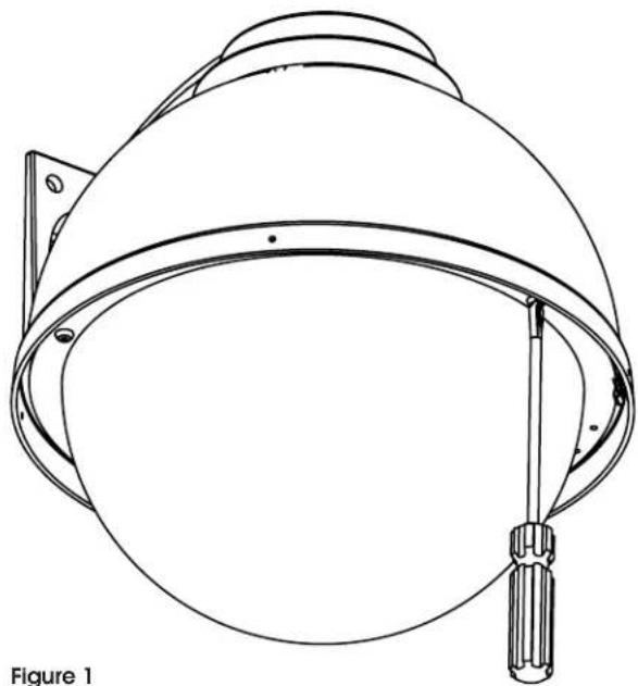
TO OPEN THE HOUSING
- Open the housing by loosening the (3) security screws located on the housing ring next to the lower clear dome (Figure 1).
natural_image
Line drawing of a helmet with tassel and side brackets, labeled Figure 1 (no text or symbols on the helmet itself)INSTALLING THE HOUSING ASSEMBLY
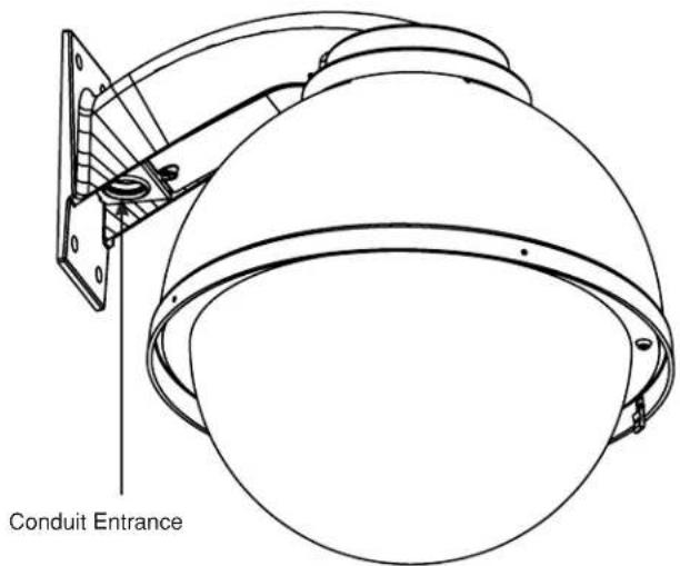
FOR WALL MOUNT, QSD
A wall mount bracket comes standard with this unit, and a template is included to use as a guide for mounting the bracket to a wall. Choose the desired location for installation and mark the drill holes using the template. Mount the wall mount bracket to the wall with (4) bolts (not provided).
NOTE: Be sure the hardware and the mounting surface can support the weight of the wall mount bracket plus the weight of the housing and drive unit. The load will be subjected to vibration from the camera motor and wind.
-
The wall mount bracket provided with the rugged housing includes a location for conduit entry. If you wish to install conduit to the bracket remove the conduit hole plug. Install fitting from below the wall mount and secure with conduit nut from inside the bracket.
-
Open the access door on the bottom of the wall mount by loosening the screw nearest the mounting plate (Figure 2).
text_image
Conduit EntranceFigure 2
- Attach the wires from the wall to the connector provided, using the wiring color code chart as a guide.
- Once all wiring connections are made, place the wires inside the wall mount bracket and close the access door. Secure with the screw removed earlier.
- Clean the outside of the dome.
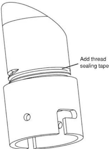
FOR OPTIONAL PENDANT MOUNT
- This unit includes a 1 1/2" NPT housing for a standard 1 1/2" NPT pipe. The RH7C can be used with other brackets designed with 1 1/2" male pipe threads, such as the Videolarm WM20G and WM20 wall mount brackets.
- Attach the housing coupling (Figure 3). NOTE: Pipe threads should be clean and rust free. Use a sealer (such as Teflon™ tape or silicone sealer) on the threads.
text_image
Add thread sealing tapeFigure 3
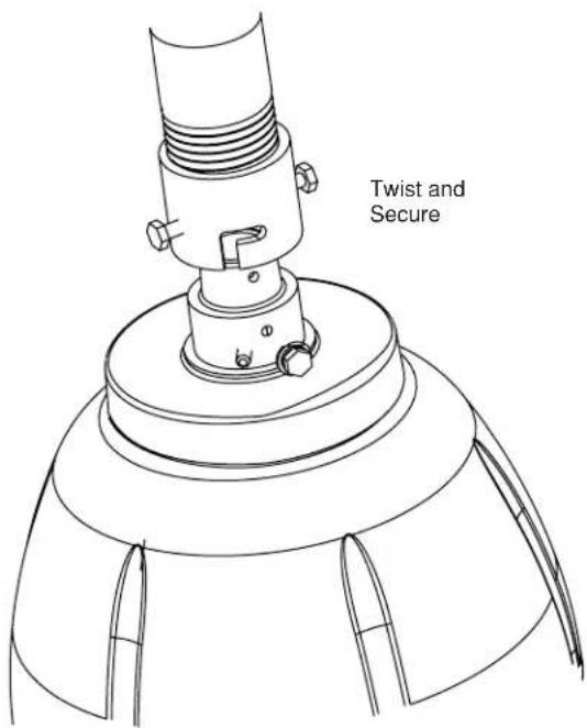
- Mount the housing assembly to the mounting bracket and housing coupling. A safety cable is included with the housing to temporarily hold it while making wiring connections.
- Clean the outside of the dome.
text_image
Twist and SecureFigure 4
Wiring Color Code for Power
POWER
| 1 Camera Power (24 VAC) Red | |
| 2 Camera Power (24 VAC) Orange | |
| 3 Accessory Power (24 VAC) Yellow | |
| 4 Accessory Power (24 VAC) Green |
CABLE AND POWER GUIDELINES
This chart shows the proper current needed for power supplies for Q-View Series cameras. Use Class 2 Power only. Input voltage must be 24 VAC/VDC.
| CAMERAS VOLTAGE CURRENT POWER | |||
| 1 24 VAC/VDC 102mA 25W | |||
| 2 24 VAC/VDC 210mA 5W | |||
| 3 24 VAC/VDC 331mA 7.9W | |||
| 4 24 VAC/VDC 487mA 10.9W | |||
Use the formula below to select the correct power supply for cameras connected in parallel (positive to positive, negative to negative):
Total current for a 24 VAC system:
| CAMERAS T | TOTAL LOAD PO | WER SUPPLY 24 A | WG 22 AWG | 18 AWG 16 | AWG | |
| 1 2.5W | 24 VAC/VDC 17 | 18/523 2733/833 690 | 9/2106 1098 | 5/3348 | ||
| 2 | 5W | 24 VAC/VC | 834/254 | 1327/404 | 3356/1023 | 5335/1626 |
| 3 | 7.9W | 24 VAC/VDC | 529/161 | 842/256 | 2129/649 | 3385/1032 |
| 4 | 10.9W | 24 VAC/VDC | 359/109 | 572/174 | 1447/441 | 2300/701 |
TOTAL CURRENT = (202mA x total number of cameras) Example: 202mA x 5 total cameras = 1010mA Note: 202mA is camera plus power supply
Video Cable Maximum Length (feet/meters)
| Cable Type RG | G-59 RG-6 | RG-11 | |
| Wire Gauge | 23 AWG* | 8 AWG* | 6 AWG* |
| Max. Length | 750/229 | 500/457 | 2000/610 |
* Copper clad steel core, 95% braided shield
Power Supply Cable Maximum Length (feet/meters)
| AWG 250/76 | 500/152 10 | 00/305 1500 | 457 2000/6 | 10 3000/914 | ||
| 18 | 3Ω | 6Ω | 13Ω | 19Ω | 26Ω | 40Ω |
| 20 | 5Ω | 10Ω | 20Ω | 30Ω | 40Ω | 59Ω |
| 22 | 8Ω | 17Ω | 33Ω | 48Ω | 66Ω | 99Ω |
| 24 | 13Ω | 26Ω | 52Ω | 78Ω | 108Ω | 163Ω |
NOTE: The above table is based on a "worst-case" power supply. Using a regulated or switching power supply can increase your cable distance. Videolarm recommends using our PS24 power supply, or a CSA/UL listed Class 2 power supply.
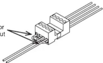
The QRH is setup with (2) individual power inputs.
- Accessory Power (yellow and green wire)
- Camera Power (red and orange)
If you wish to provide a single power transformer it is recommended that:
- Be certain that you know the total power consumption of the housing Heaters (25 watts) + Blowers (2 watts) + camera/pan-tilt (not supplied)
- Check the supplied wiring chart to be sure that you have the proper gauge wire for the distance that you intend to run your power wires.
- Bring power to the 3 and 4 position of the power connector (yellow and green wire)
- Two jumpers are provided in the housing packet. Jumper from the 1^st position to the 3^rd position and from the 2^nd position to the 4^th position of the terminal block. Be careful not to short between the yellow and green wires.
Add 2 jumpers for single power input
text_image
or outFigure 5
24k VAC Wiring Distances
Maximum Length (feet/meters)
The following are the recommended maximum distances for 24 VAC with a 10% voltage drop (10% is generally the maximum allowable voltage drop for AC powered devices).
Wire Gauge
| Total vA consumed | 22 | 20 | 18 | 16 | 14 | 12 | 10 |
| 5.5 | 250 | 400 | 600 | 960 | - | - | - |
| 10 | 120 | 180 | 300 | 480 | 800 | 1300 | - |
| 20 | 89 | 141 | 225 | 358 | 571 | 905 | 1440 |
| 30 | 65 | 90 | 130 | 225 | 350 | 525 | 830 |
| 40 | 44 | 70 | 112 | 179 | 285 | 452 | 720 |
| 50 | 35 | 56 | 90 | 143 | 228 | 362 | 576 |
| 60 | 29 | 47 | 75 | 119 | 190 | 301 | 480 |
| 70 | 25 | 40 | 64 | 102 | 163 | 258 | 411 |
| 80 | 31 | 34 | 55 | 85 | 140 | 215 | 340 |
| 90 | 19 | 31 | 50 | 79 | 126 | 201 | 320 |
| 100 | 17 | 28 | 45 | 71 | 114 | 181 | 288 |
| 110 | 16 | 25 | 41 | 65 | 103 | 164 | 261 |
| 120 | 14 | 23 | 37 | 59 | 95 | 150 | 240 |
| 130 | 13 | 21 | 34 | 55 | 87 | 139 | 221 |
| 140 | 12 | 20 | 32 | 51 | 81 | 129 | 205 |
| 150 | 11 | 18 | 30 | 47 | 76 | 120 | 192 |
| 160 | 11 | 17 | 28 | 44 | 71 | 113 | 180 |
| 170 | 10 | 16 | 26 | 42 | 67 | 106 | 169 |
| 180 | 9 | 15 | 25 | 39 | 63 | 100 | 160 |
| 190 | 9 | 14 | 23 | 37 | 60 | 95 | 151 |
| 200 | 8 | 14 | 22 | 35 | 57 | 90 | 144 |
Maximum distance from transformer to load
CAMERA ADJUSTMENT
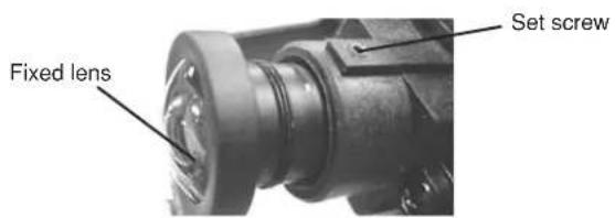
- Access the cameras by removing the dome. Loosen the locking screws on the lip of the dome. DO NOT TAKE THESE SCREWS OUT. Once the screws are loosened, turn the dome counter clockwise until it stops, then pull the dome off.
Fixed Lens: Loosen the set screw in the lens mount. Manually rotate the lens until a clear picture is achieved. Once the focus is set, retighten the set screw (Figure 5).
text_image
Fixed lens Set screwFigure 5
Auto Iris Lens:
NOTE: THE AUTO IRIS LENS IS SET AT THE FACTORY.
• IF YOU EXPERIENCE VIDEO TOO LIGHT OR DARK AUTO IRIS ADJUSTMENT MAY BE NEEDED.
SEE THE TROUBLESHOOTING SECTION FOR ADJUSTMENT INFORMATION.
CAMERA SETTINGS
NOTE: To determine which camera is used in your unit, locate the serial number on the inside of the housing. Match the two letter prefix with the corresponding instructions included here for adjustments.
HIGH-RES BLACK & WHITE
FIXED AND FIXED VARI-FOCAL LENSES. There are no user adjustable settings on these units (Figure 7).
BW Fixed and Vari-Focal
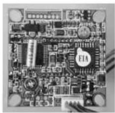
natural_image
Close-up of a printed circuit board with visible traces and components (no readable text or symbols)Figure 7
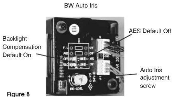
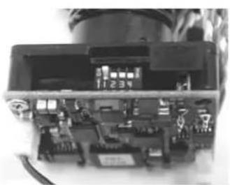
AUTO IRIS LENSES. The dip switches are factory set with AES off and backlight compensation on (Figure 8). The auto iris is also set at the factory, but an adjustment screw is included for use if needed. See page 10 for instructions on adjusting Auto Iris.
text_image
BW Auto Iris Backlight Compensation Default On AES Default Off Auto Iris adjustment screw Figure 8HIGH-RES COLOR, FIXED LENS
FIXED AND FIXED VARI-FOCAL LENSES. There are no user adjustable settings on these units (Figure 14) AUTO IRIS LENSES: The auto iris can be adjusted if needed. See the Troubleshooting section for instructions.
text_image
Auto Iris adjustment screwFigure 14
HIGH-RES COLOR & DAY/NIGHT w/AUTO-IRIS
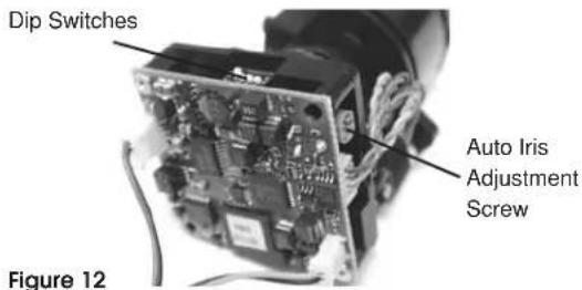
NOTE: This hi-res color camera uses a 1/4" chip and a 3-6mm auto iris lens. It is comparable to a 1/3" chip using a 4-9mm auto iris lens.
The operational settings are defined by four dip switches located on the side of the PC Board (Figure 12 and 13). Moving the switches to the UP position will activate specific settings. Refer to the chart below.
text_image
Dip Switches Auto Iris Adjustment Screw Figure 12Figure 12
natural_image
Interior view of an electronic device showing internal components and wiring (no visible text or symbols)Figure 13
| Dip Switch | UP | DOWN |
| 1(Iris) | Auto Iris On | Position for Fixed Lens |
| 2(Flickerless) | Shutter speedfixed at 1/100 sec. | Normal |
| 3 (Back LightCompensation | ON | Normal |
| 4(Synch Mode) | Internal Synch | Line Lock Mode |
COMPLETION OF INSTALLATION
- When the desired focus is achieved for each camera, adjust the segmented bracket arms to the desired viewing angle. Once you've finished, put the dome back in place and check to be sure none of the cameras touch the dome. If one or more do, readjust the arm(s) until they are clear of the dome.
- Reattach the dome by putting it in place, turning clockwise until it locks, and then tightening the locking screws.
NVT INSTRUCTIONS
UNSHIELDED TWISTED PAIR VIDEO WIRING

NOTE: The customer must purchase the Video Transceiver from NVT. Part numbers are:
• NV-212A (500 ft.)
* NV-213A or NV-213A-M (1000 ft.)
• NV-652R, NV-862R, or NV-1662R (3000 ft.)
The cameras included in the Q-View™ series have the option of transmitting video signals to NVT receivers via unshielded twisted pair cable. You must purchase the receiver separately. Instructions for connecting the receiver end of the the unshielded twisted pair cable will be included with the NVT receiver. Following are instructions for connecting the unshielded twisted pair cables to the RJ45 (Cat. 5) cable running outside your housing.
- Video for all four cameras is contained in the one RJ45 (Cat. 5) cable. An RJ45 female coupling is provided so that all connections can be made with an RJ45 connector. The following is the wiring diagram for the four twisted pair wires that are included with the Cat. 5 cable.
| PIN | WIRE COLOR | CAMERA NUMBER |
| 1 | White/Green | Camera 1 + |
| 2 | Green | Camera 1 - |
| 3 | White/Orange | Camera 2 + |
| 6 | Orange | Camera 2 - |
| 5 | White/Blue | Camera 3 + |
| 4 | Blue | Camera 3 - |
| 7 | White/Brown | Camera 4 + |
| 8 | Brown | Camera 4 - |
- Connect the other end of the unshielded twisted pair cable to the NVT receiver.
CAUTION: The unshielded twisted pair video signal is polarity dependent. The positive video wire for each camera MUST be connected to the positive terminal on the NVT receiver, and negative MUST be connected to negative.
- When using unshielded twisted pair cable you DO NOT need the BNC connector. All four BNC connectors are provided inside the housing for testing purposes. Be sure that there is no video connection other than the unshielded twisted pair cable.
Wiring Notes
Wire — What to DO
- DO use point-to-point Unshielded Twisted Pair wire, gauge 24 or thicker, stranded or solid, Category 2, 3, 4, or 5.
- The video signal may co-exist in the same wire bundle as other video, telephone, data, control signals, or low-voltage power. It is also OK to run NVT video signals in or near electromagnetic fields (in accordance with National Electrical Code, local, or other local safety requirements).
- DO measure the wire distance. Use only transceivers that are designed for that distance.
- DO make sure the pair of wires carrying the video signal is sent as a twisted pair (e.g. the blue-white/white-blue wires twisted together as a pair), not a "split-pair" (e.g. blue-white conductor, part of one pair/orange-white conductor, part of another pair).
Wire — What NOT to DO
- DO NOT USE SHIELDED TWISTED PAIR WIRE. It will severely degrade the distance performance. Short runs may be used with some signal degradation (for example elevator traveler cables). Multi-pair wire with an overall shield is OK.
- DO NOT USE UN-TWISTED WIRE. It will reduce the NVT product's inherent interference immunity.
- DO NOT allow your installation to have "bridge-taps", loading coils, talk-battery, or MOV type protectors. Bridge-taps are where a twisted pair is connected to two twisted pairs (such as an extension phone at home). Bridge-taps cause reflections as the signal propagates, resulting in "ghosts" in the video image, and are to be avoided.
- If the phone company is providing the cable runs between buildings, make sure it's "dry copper" i.e. it should have none of the following: dial-tone, 48 volts, loading coils, bridge-taps, switching, or long paths to the phone company's central office and back.
- Due to near-end crosstalk, DO NOT send a transmit and a receive signal in the same wire bundle. Exceptions: Less than 1,000 ft (300m), or Category 5 cable, up to 2,000 ft (600m) are OK.
- DO NOT send "Up-the-Coax" Pan/Tilt/Zoom signals through active (amplified) NVT transceivers.

- For safety, never put NVT signals in the same conduit as high-voltage wiring.

- WARNING — to reduce a risk of fire or electrical shock, do not expose this product to rain or moisture.
Measure your wire distance
Note: All NVT quoted distance specifications include any coax in the run. It is recommended that the wire distance be measured to ensure that the capability of the NVT product is correct.
Wire resistance may be measured with an ohm-meter by shorting the two conductors together at the far end, and measuring the loop-resistance out and back. Compare your readings with the charts in the next column.
| Cable Distance | Unshielded Twisted-Pair Wire Gauge (AWG) | ||||
| 18 | 19 | 20 | 22 | 242220 | |
| 250 ft 3 | 4 | 5 | 8 | 13 | □ |
| 300 ft 4 | 5 | 6 | 10 | 16 | □ |
| 400 ft 5 | 6 | 8 | 18 | 21 | □ |
| 500 ft 6 | 8 | 10 | 16 | 26 | □ |
| 600 ft 8 | 10 | 12 | 19 | 31 | □ |
| 800 ft 10 | 13 | 16 | 25 | 42 | □ |
| 1000 ft 13 | 16 | 20 | 32 | 52 | □ |
| 1250 ft 16 | 20 | 25 | 40 | 65 | □ |
| 1500 ft 19 | 24 | 30 | 48 | 78 | □ |
| 1750 ft 23 | 28 | 35 | 55 | 91 | □ |
| 2000 ft | 26 | 32 | 40 | 63 | 104 |
| 2500 ft | 32 | 40 | 49 | 79 | 131 |
| 3000 ft | 39 | 48 | 59 | 95 | 157 |
| 3500 ft | 45 | 56 | 69 | 111 | 183 |
| 4000 ft | 52 | 64 | 79 | 127 | 209 |
| 5000 ft | 65 | 80 | 99 | 158 | 261 |
| 6000 ft | 78 | 95 | 119 | 190 | 313 |
| 8000 ft | 104 | 127 | 158 | 253 | 418 |
| Cable Distance | Unshielded Twisted-Pair Wire Gauge (AWG) | ||||
| 18 | 19 | 20 | 22 | 242220 | |
| 75 m | 3 | 4 | 5 | 8 | 13 |
| 100 m | 4 | 5 | 6 | 10 | 17 |
| 125 m | 5 | 7 | 8 | 13 | 21 |
| 150 m | 6 | 8 | 10 | 16 | 26 |
| 200 m | 9 | 10 | 13 | 21 | 34 |
| 300 m | 13 | 16 | 19 | 31 | 51 |
| 400 m | 17 | 21 | 26 | 42 | 69 |
| 500 m | 21 | 26 | 32 | 52 | 86 |
| 600 m | 26 | 31 | 39 | 62 | 103 |
| 750 m | 32 | 39 | 49 | 78 | 129 |
| 900 m | 38 | 47 | 58 | 94 | 154 |
| 1000 m | 43 | 52 | 65 | 104 | 171 |
| 1200 m | 51 | 63 | 78 | 125 | 206 |
| 1500 m | 64 | 78 | 97 | 156 | 257 |
| 1800 m | 77 | 94 | 117 | 187 | 309 |
| 2400 m | 102 | 125 | 156 | 249 | 411 |
| Cable Distance | Unshielded Twisted-Pair Wire Gauge (mm) | |||||
| 1.0 | 0.8 | 0.7 | 0.6 | 0.50 | 60 | |
| 75 m | 3 | 5 | 6 | 9 | 13 | |
| 100 m | 4 | 7 | 9 | 12 | 18 | |
| 125 m | 6 | 8 | 11 | 15 | 22 | |
| 150 m | 7 | 10 | 13 | 18 | 27 | |
| 200 m | 9 | 13 | 17 | 24 | 36 | |
| 300 m | 13 | 20 | 26 | 36 | 54 | |
| 400 m | 18 | 27 | 35 | 48 | 72 | |
| 500 m | 22 | 33 | 43 | 60 | 90 | |
| 600 m | 26 | 40 | 52 | 72 | 108 | |
| 750 m | 33 | 50 | 65 | 89 | 135 | |
| 900 m | 40 | 60 | 78 | 107 | 162 | |
| 1000 m | 44 | 66 | 86 | 119 | 179 | |
| 1200 m | 53 | 80 | 104 | 143 | 215 | |
| 1500 m | 66 | 100 | 130 | 179 | 269 | |
| 1800 m | 79 | 120 | 155 | 215 | 323 | |
| 2400 m | 106 | 159 | 207 | 286 | 431 | |
NVT TROUBLESHOOTING
If you are experiencing problems, attempt to simplify your setup. Test each cable segment separately. For example, test the camera and monitor together without the other equipment. Then add in the NVT transceivers, back-to-back. Test each segment of a long cable-run independently. Attempt to isolate the problem.
Below are problems that may be encountered. If the suggestions below are not helpful, or the recommendations are not effective, please call NVT's customer support. NVT customer support can be reached 8:00 AM to 5:30 PM PST at (800) 959-9870 or at (+1) (650) 562-0600.
FAINT OR BLURRY PICTURE; LITTLE OR NO COLOR
Possible causes include:
- Shielded twisted-pair cable. Verify that the wire is unshielded twisted-pair cable. Multi-pair cable with an overall shield is OK.
- Longer wire distance than expected. Be sure to include any coax cable that's part of this distance. Verify end-to-end connectivity with an ohm meter. Measure the distance by disconnecting the transceivers, shorting the far end, reading the loop's resistance at the near end. See above for ohm vs. distance ratings. If necessary, replace transceivers with correct models specified for this distance.
- Incorrect distance equalization setting. Adjust the equalization controls) with a mini screwdriver (NV-652R, NV-862R or the NV-1662R). If the transmitter is an NV-653T, verify correct equalization switch setting.
- Poor connection at a punch-block, splice, or coax cable. Re-check using the method described in #2 above, or use a wire test set.
- Short between conductors of the twisted-pair. Use an ohm meter to locate the short.
- Transient protection devices employing metal-oxide varistors. Use carbon blocks, gas-discharge tubes, or NVT transceivers with built-in protection.
- Check the camera. Are the focus and iris set correctly? Verify with portable monitor.
EXTREMELY FAINT PICTURE
Only faint shadows of the original picture are visible. One of the twisted pair conductors is open or the wires are shorted together. Check with an ohm meter.
OVER-SATURATED COLORS; HIGH CONTRAST GRAINY PICTURE; TOO BRIGHT, TORN PICTURE
Adjust the distance equalization as necessary. Verify that the monitor has a 75 termination, not in "loop-through".
WON'T SYNC; WIDE, WHITE JAGGED AREAS
Looks like a scrambled Cable TV signal. Check polarity.
WON'T SYNC; TORN PICTURE
- Make sure that you are using unshielded twisted pair wire.
- Check distance equalization settings.
- For installations with passive (non-amplified) transceivers at both ends, check for ground loops. This may be done with an AC Voltmeter, as shown below:
If the voltage is greater than 1/2 volt, use an amplified receiver, such as the NV-652R, NV-862R, or NV-1662R.
Alternately, remove the ground at one end (usually at the camera end). Be sure that floating the camera conforms to local/regional and National Electrical Codes.
- Check for crosstalk from a second video path. Disconnect all other video sources. If the problem goes away, check for a split-pair or un-twisted wire.
FAINT STRIPES GLIDING UP OR DOWN THE SCREEN
These are caused by crosstalk from a second video path, or with ground-loops in installations employing passive models at both ends.
-
To identify, disconnect all other video signals temporarily. If the interference goes away, check the wire to make sure the signal is traveling through a twisted pair. Is two-way video being sent more than 1,000 ft (300m) over Category 2 or 3 wire? If so, the send and receive signals may need to go in separate jacketed cables, or upgrade to Category 5 wire.
-
Next, check for ground loops. See #3 above.
Check the blue "power" LED on powered NVT units. If the light is not on, the receiver is not getting power. Re-check the power source and connections.
If the green LED is on but the power LED is off, check that the power supply is floating. Grounding one side of the power input may cause this condition.
The NV-652R, NV-862R or NV-1662R series receiver/hub is not detecting a video signal. There is an open or shorted connection. Use a multimeter to locate the fault.
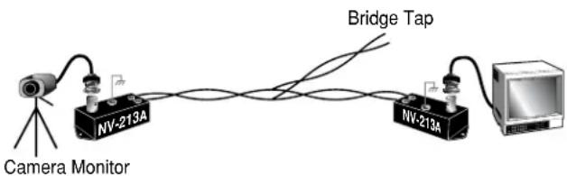
GHOSTS
Faint shadows of the original signal shifted to the right. This is caused by an impedance mismatch along the wire. Verify that the monitor is terminated with 75 (not in "loop-through".) Check that all wire is unshielded twisted pair. The high-frequency wire impedance should be 100. Check for bridge-taps (see below) either by inspecting wiring closet connections, or, if available, using a "Time-Domain Reflectometer" (T.D.R.), sometimes called a "cable tester".
If the faint shadows are not copies of the original picture, but from the picture of some other camera, check for crosstalk:
Is any portion of the wire un-twisted?
Are the signals from two cameras split between two pairs?
Is there a short between a conductor of one signal and a conductor of another?
text_image
Camera Monitor NV-213A Bridge Tap NV-213A
text_image
AC VoltmeterTROUBLESHOOTING
If you experience problems with the camera picture please check these simple troubleshooting procedures for possible solutions before calling technical support.
STATIONARY OR SCROLLING HORIZONTAL LINES ON SCREEN
GROUND LOOPS
Generally a horizontal line on screen, whether moving or stationary, means you have a ground loop problem. The video shield should only be connected to ground through the monitor or other electronic equipment that uses the video signal. Connecting the video shield to ground at the camera will create a ground loop, which may interfere with the video signal (See Figure A). This should not damage the camera, but the video signal may become unusable. A ground loop problem will cause a dark horizontal bar to slowly "scroll" through the picture. To solve this problem, remove all ground connections from the video connection EXCEPT for the ground at the terminating end of the video signal.
The video termination should be a 75-ohm impedance, standard in monitors and other video equipment. If the video signal goes to more than one piece of equipment, a monitor and multiplexer input for instance, insure that one and only one piece of equipment terminates the video signal with 75 ohms; otherwise the image will be degraded and may appear to be unusually dim.
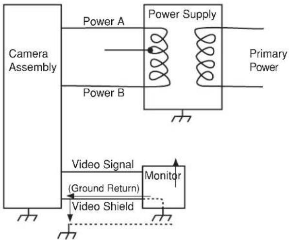
flowchart
graph TD
    A["Camera Assembly"] --> B["Power Supply"]
    B --> C["Primary Power"]
    B --> D["Video Signal (Ground Return)"]
    D --> E["Monitor"]
    E --> F["Video Shield"]
    F --> G["Power A"]
    F --> H["Power B"]
Figure A Ground Loop
IMPORTANT NOTE: If you have removed the ground loop and the horizontal line still remains on screen call Videolarm technical support for further information.
LINE LOCK
All cameras are all shipped from the factory with the line lock function disabled. If your application requires Line Lock contact Videolarm.
AUTOMATIC BROWN OUT FEATURE
The camera includes an automatic brown out feature which is activated whenever the incoming voltage drops below 10 VAC or VDC.
PICTURE IS CLEAR, LOW OR NO COLOR;
PICTURE IS DARK OR GRAINY IN GOOD LIGHTING CONDITIONS
The auto iris lens is set at the factory. If you experience video too light or dark you can manually adjust using the auto iris adjustment screw.
If there is low or no color the Auto Iris is too open, if the picture is dark or grainy in good conditions the Auto Iris is too closed.
To adjust the auto iris lens, first locate the AUTO IRIS ADJUSTMENT SCREW on the camera PC board. Using a small insulated screwdriver (blade width of from 1/16" to 3/32"), adjust the control. Turning the control CLOCKWISE opens the iris, making the image brighter.
Turning the control COUNTER CLOCKWISE closes the iris, making the image darker.
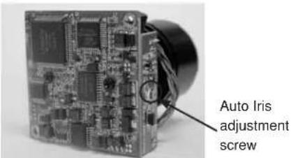
BLACK & WHITE AUTO-IRIS
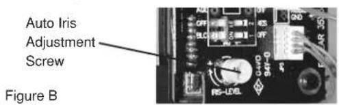
text_image
Auto Iris Adjustment Screw Figure BCOLOR & DAY/NIGHT AUTO-IRIS
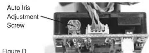
text_image
Auto Iris Adjustment Screw Figure DIMPORTANT NOTE ON AUTO IRIS ADJUSTMENT:
WHEN ADJUSTING, USE A SMALL, INSULATED
SCREWDRIVER. The auto iris adjustments are very sensitive. Use gentle pressure when turning. To adjust, turn either clockwise or counter-clockwise no more than one degree at a time. Check the monitor after each turn to determine is the desired brightness and color have been obtained. When the adjustment is satisfactory, place a hand over the lens to block out all light. Quickly remove the hand to be sure the iris reacts.
Mounting Template
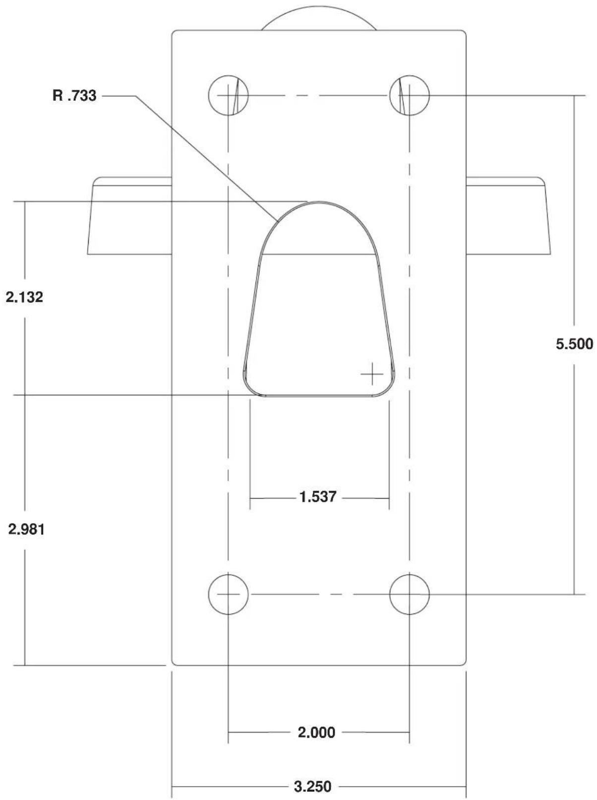
text_image
R .733 2.132 5.500 1.537 2.981 2.000 3.250Product Registration/Warranty
Thank you for choosing Videolarm. We value your patronage and are solely committed to providing you with only the highest quality products available with unmatched customer service levels that are second-to-none in the security industry.
Should a problem arise, rest assure that Videolarm stands behind its products by offering some of the most impressive warranty plans available: 3 Years on all Housings, Poles, Power Supples, and Accessories and 5 Years on all camera systems (SView, QView, Warriors), and InfraRed Illuminators.

Register Your Products

Option 1: Online Option 2: Mail-In
Take a few moments and validate your purchase with our Online Product Registration Form at www.videolarm.com/productregistration.jsp or complete and mail-in the bottom portion of this fl yer.
Register your recent Videolarm purchases and benefit from the following:
• Simple and Trouble-Free RMA process
- Added into customer database to receive product updates / news
- Eliminate the need to archive original purchase documents:
Receipts, Purchase Orders, etc...
Cut at the dotted Line
Place in envelope, affi x stamp and mail to: Videolarm ATTN: Warranty
2525 Park Central Ave.
Decatur, GA 30035
Main Contact Info
First Name:
Professional Title:
Address 1:
City: ____
Zip / Postal Code: ____ Phone Number:
Last Name:
Company:
Address 2:
/ Province/Country:
E-mail Address: ____
Product Information
Please Circle One: Business Personal
Name & Location of Company / Store where Purchased: ____
(City, State, Country)
Videolarm Product ID
Product Description
Serial # ____
(Available only for Camera Systems, IR Illuminators, Wireless Devices)
PO#