HWAC-1217S - Air-conditioner HONEYWELL - Free user manual and instructions
Find the device manual for free HWAC-1217S HONEYWELL in PDF.

| Product Type | Portable Air Conditioner |
| Model | HWAC-1217S |
| Cooling Capacity | 12,000 BTU/h |
| Coverage Area | Up to 400 sq. ft. |
| Dimensions (WxDxH) | 15.6 x 13.3 x 27.2 inches |
| Weight | 65 lbs |
| Power Supply | 115V, 60Hz |
| Power Consumption (Cooling) | 1050 watts |
| Amps | 9.5 |
| Refrigerant | R-410A |
| Energy Efficiency Ratio (EER) | 11.4 |
| Operating Modes | Cool, Fan, Dehumidify, Auto |
| Fan Speeds | 3 (Low, Medium, High) |
| Dehumidification Capacity | 50 pints/day |
| Airflow | 320 CFM (max) |
| Noise Level | 52 dB (Low), 56 dB (High) |
| Remote Control | Yes, included |
| Timer | 24-hour programmable |
| Filter | Washable mesh filter |
| Maintenance | Clean filter every 2 weeks; drain condensate as needed |
| Safety Features | Auto-restart after power loss, compressor protection delay |
| Installation | Includes window kit for sliding or double-hung windows |
| Warranty | 1 year limited |
Frequently Asked Questions - HWAC-1217S HONEYWELL
User questions about HWAC-1217S HONEYWELL
0 question about this device. Answer the ones you know or ask your own.
Ask a new question about this device
Download the instructions for your Air-conditioner in PDF format for free! Find your manual HWAC-1217S - HONEYWELL and take your electronic device back in hand. On this page are published all the documents necessary for the use of your device. HWAC-1217S by HONEYWELL.
USER MANUAL HWAC-1217S HONEYWELL
Mini-Split Air Conditioner Single Zone Installation and Operations Manual
HWAC-1217S
HWAC-1817S
HWAC-2417S
CONTENTS
SPECIFICATIONS 3
SAFETY INSTUCTIONS, INSTALLATION 4-5
PRODUCT VIEW 6
NOTICE FOR INSTALLATION 7-9
INSTALLATION: INDOOR UNIT 10-13
INSTALLATION: OUTDOOR UNIT 14-17
NOTICES FOR USE 18-19
TEST OPERATION 19
SAFETY INSTRUCTIONS, UNIT OPERATION 20
REMOTE CONTROL FUNCTIONS 21-23
AIR CONDITIONER OPERATION 24-25
Thank you for purchasing the HWAC-1217S, HWAC-1817S, or HWAC-2417S Mini-Split Air Conditioner.
This manual will provide you with safety information, installation steps, instructions for optimal use, and proper care and maintenance for your product. Please read this manual carefully before operating.
SPECIFICATIONS
| MODEL | HWAC-1217S | HWAC-1817S | HWAC-2417S |
| Cooling Capacity Heating Capacity | 12,000 BTU Cooling 12,500 BTU Heating | 18,000 BTU Cooling 18,000 BTU Heating | 23,000 BTU Cooling 24,000 BTU Heating |
| SEER Rating 17 17 17 | |||
| Room Size (Sq. ft.) | 300-500 | 600-800 | 900-1,200 |
| Voltage / Frequency 115V / 60 Hz 230V / 60 Hz 230V / 60 Hz | |||
| Dehumidification | 2.11 pnt/h | 3.38 pnt/h | 6.34 pnt/h |
| Operating Sound Level | Indoor Unit: 42 dB Outdoor Unit: 52 dB | Indoor Unit: 46 dB Outdoor Unit: 55 dB | Indoor Unit: 49 dB Outdoor Unit: 55 dB |
| Ambient Range | 61°F-90°F | 61°F-90°F | 61°F-90°F |
| Refrigerant R410a R410a R410a | |||
| Cord Length | 14.8 ft. (4.5 m) | 14.8 ft. (4.5 m) | 14.8 ft. (4.5 m) |
| Zone Capacity Single | Single | Single | |
| Indoor Unit Dimensions (W x D x H) | 34.68"W x 8.07"D x 11.65"H | 35.40"W x 8.90"D x 12.2"H | 42.6"W x 9.17"D x 12.99"H |
| Outdoor Unit Dimensions (W x D x H) | 28.74"W x 11.22"D x 21.46"H | 31.90"W x 11.80"D x 21.90"H | 32.48"W x 12.20"D x 25.79"H |
| Indoor Unit Weight | 22 lbs. | 24 lbs. | 31 lbs. |
| Outdoor Unit Weight | 57 lbs. | 62 lbs. | 94 lbs. |
| Safety Certification | cETLus | cETLus | cETLus |
SAFETY INSTRUCTIONS - INSTALLATION
Always be careful when using the machine. To reduce the risk of fire, electrical shock, or other injuries, keep these safety considerations in mind when installing, using, and maintaining your machine.

WARNING
- The air conditioner must be properly grounded on a level surface. Do not connect the grounding wire to the gas pipeline, water pipeline, lightning rod, or telephone grounding wire.
- Always switch off the device and cut the power supply when the unit is not in use for a long time.
- Do not let the remote control or the indoor unit get wet.
- Make sure the voltage meets the appliance's electricity requirements.
- Do not operate if the electrical plug or power cord is damaged.
- Do not under any circumstances alter the electrical plug.
- Do not turn off the main power switch during operation with wet hands.
- Do not share the electrical socket with other appliances.
- Always switch off the device and cut the power supply before performing any maintenance or cleaning.
- Do not yank on the power cable to unplug.
- An earth leakage breaker with rated capacity must be installed.
- Do not install the air conditioner in a place where there is flammable gas or liquid. The distance between them should be more than 4.5 ft.
- Do not use air conditioner in stormy weather. Power supply should be cut in time to prevent danger.
- Do not block air inlets or air outlets.
- Do not insert hands or any objects into the air inlets or air outlets.
- Please pull on the mounting bracket and check if it is secure to the wall.
- Don't let the air conditioner blow against a heater appliance. Otherwise, it will lead to carbon monoxide poisoning.
- The appliance shall be installed according to the installation instructions supplied and in accordance with national wiring regulations.
- Do not modify any part of this product.
- Do not operate this appliance for any other purpose other than its intended use.
SAFETY INSTRUCTIONS - INSTALLATION
Always be careful when using the machine. To reduce the risk of fire, electrical shock, or other injuries, keep these safety considerations in mind when installing, using, and maintaining your machine.

CAUTION
- Do not open windows and doors for a long time when the air conditioner is running. This will cause the cooling or heating capacity to be weakened.
- Do not stand /sit on top of the outdoor unit and do not place heavy items on it.
- Do not apply cold air from the unit to the body for a prolonged time.
- It is recommended that the temperature difference between indoor and outdoor temperature should not be too large. Appropriate adjustments of the setting temperature can prevent the waste of electricity.
- If your air conditioner is not fitted with a supply cord and a plug, an all-pole switch must be installed in the fixed wiring and the distance between contacts should be no less than 0.1 inch.
- If your air conditioner is permanently connected to the fixed wiring, a residual current device (RCD) having rated residual operating current not exceeding 30 mA should be installed in the fixed wiring.
- The power supply circuit should have leakage protector and air switch of which the capacity should be more than 1.5 times of the maximum current.
NOTE:
- This product contains fluorinated greenhouse gases. Never try to interfere with the refrigerant circuit yourself or disassemble the product yourself and always ask a professional. The specification of the fuse is printed on the circuit board, such as: 3.15A/250V AC, etc. Refrigerant leakage contributes to climate change. Refrigerant with lower global warming potential (GWP) would contribute less to global warming than a refrigerant with higher GWP, if leaked to the atmosphere. This appliance contains a refrigerant fluid with a GWP equal to [2088]. This means that if 1 kg of this refrigerant fluid would be leaked to the atmosphere, the impact on global warming would be [2088] times higher than 1 kg of CO2, over a period of 100 years.
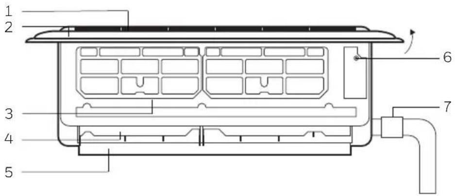
PRODUCT VIEW
Indoor Unit, Open view
- Air Inlet Grille
- Panel
- Air Filter
- Air Louvre
- Air Vent
- Force Switch
- Pipe Protector Ring
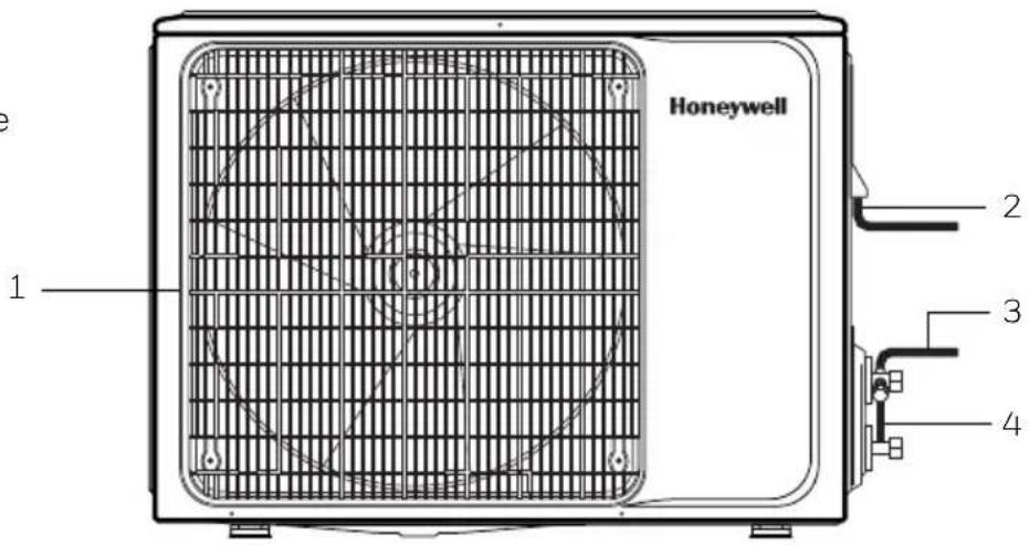
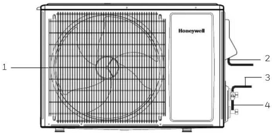
Outdoor Unit
- Air Outlet Grille
- Power Cable
- Connecting Pipe
- Drain Hose Outlet/Pipe
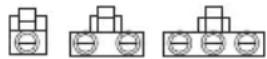
12k and 24k BTU Version
18k BTU Version
NOTICE FOR INSTALLATION
Important Notices
- Before installing, please contact a local HVAC professional. If the unit is not installed by a registered HVAC contractor, the warranty will be voided. Please request a copy of the HVAC contractor's invoice at the end of installation and keep for your records.
- The air conditioner must be installed by professionals according to the national wiring rules and this manual.
- To move and install the air conditioner in another place, please contact a certified HVAC professional.
Requirements for Installation Location
- Avoid places of inflammable or explosive gas leakage or where there are strongly aggressive gases.
- Avoid places subject to strong artificial electric/magnetic fields.
- Avoid places subject to noise and resonance.
- Avoid severe natural conditions (e.g., heavy lampblack, strong sandy wind, direct sunshine, or high temperature heat sources).
- Avoid places within the reach of children.
- Allow for a short connection between the indoor and outdoor units.
- Select where it is easy to perform service and repair, also where ventilation is good.
- The outdoor unit shall not be installed in any way that could occupy an aisle, stairway, exit, fire escape, catwalk, or any other public area.
- The outdoor unit shall be installed as far as possible from doors, windows, and plants/trees.
Requirements for the Mounting Plate
- The mounting plate must meet the relevant national or industrial standards in terms of strength with welding and connection areas rustproofed.
- The mounting plate and its load carry surface shall be able to withstand 4 times above the weight of the unit, or 440.9 lbs., whichever is heavier.
- The mounting plate of the outdoor unit shall be fastened with an expansion bolt.
- Ensure a secure installation to prevent damage to surrounding areas.
NOTE: Mounting plate not included.
NOTICE FOR INSTALLATION
Electrical Safety Requirements
- Be sure to use the rated voltage and air conditioners dedicated circuit for the power supply, and the power cord diameter must meet the national requirements.
- When the maximum current of air conditioner is ≥ 16A , it must use the air switch or leakage protection switch equipped with protection devices.
• The normal operating range is 90%-110% of the local rated voltage. - The minimum clearance between the air conditioner and the combustibles is 4.5 ft.
- The interconnection cord connects the indoor and outdoor units. You must first choose the right cable size before preparing it for connection.
•Cable types:
• Outdoor Power Cable: H07RN-F or H05RN-F
• Interconnection Cord: H07RN-F or H05RN-F
Minimum Cross-Sectional Area of Power Cable and Interconnection Cord
| North America | |
| ApplianceAmps | AWG |
| 10A | 18 >3 and |
| 13A 16 >6 | and ≤10A 1mm2 |
| 18A 14 >10 | and ≤16A 1.5mm |
| 25A 12 >16 | and ≤25A 2.5mm |
| 30A 10 >25 | and ≤32A 4mm2 |
| 40A 8 >32 | and ≤40A 6mm2 |
| Other Regions | |
| Rated Current of Appliance | Nominal Cross-Sectional Area |
| A 0.75mm^2 | |
- The size of the interconnection cord, power cable, fuse, and switch needed is determined by the maximum current of the unit. The maximum current is indicated on the nameplate located on the side panel of the unit. Refer to this nameplate to choose the right cable, fuse, or switch.
NOTE: For the number of cores in the cable refer to the detailed wiring diagram adhered on the unit.
NOTICE FOR INSTALLATION
Requirements for Operations at Raised Height
- When carrying out installation at 6.6 ft. or higher above the base level, safety belts must be worn and ropes of sufficient strength be securely fastened to the outdoor unit, to prevent falling that could cause personal injury or death as well as property loss.
Grounding Requirements
- The air conditioner is the type I electrical appliance and must ensure a reliable grounding.
- Do not connect the grounding wire to a gas pipe, water pipe, lightning rod, telephone line, or a circuit poorly grounded to the earth.
- The grounding wire is specially designed and shall not be used for other purpose, nor shall it be fastened with a common tapping screw.
Others
- The connection method of the air conditioner and the power cord and the interconnection method of each independent element shall be subject to the wiring diagram affixed to the machine.
Packing List
| Packing List of the Indoor Unit | ||
| Name | Quantity | Unit |
| Indoor Unit | 1 | PC |
| Remote Controller | 1 | PC |
| Batteries (7#) | 2 | PC |
| Instructions | 1 | Set |
| Drain Pipe | 1 | PC |
| Packing List of the Outdoor Unit | ||
| Name | Quantity | Unit |
| Outdoor Unit | 1 | PC |
| Connecting Pipe | 2 | PC |
| Plastic Tape | 1 | Roll |
| Pipe Protection Ring | 1 | PC |
| Luting (Putty) | 1 | Packet |
INSTALLATION: INDOOR UNIT
Clearance Requirements for Indoor Installation
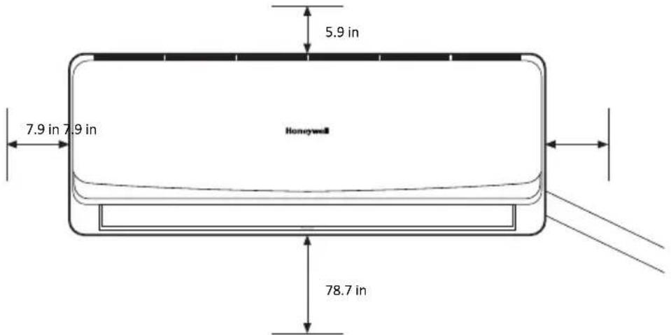
NOTE: All measurements should be no less than posted from obstructions.
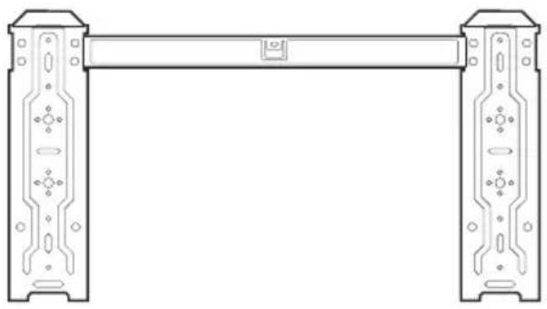
Mounting Plate
- The wall for installation of the indoor unit shall be hard and firm to prevent vibration.
- Use the “+” type screw to fasten the mounting plate. Horizontally mount the mounting plate on the wall and ensure it is level with the wall.
- Pull the mounting plate by hand after installing to confirm if it is solid.
natural_image
Technical line drawing of a mechanical bracket or frame structure (no text or symbols)Wall-Through Hole
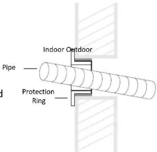
- Make a 60-80mm hole as appropriate, where there are no obstructions for drilling. The indoor connection pipe should slant outwardly by 10-20°.
- To protect the piping and the cables from being damaged running through the wall, the pipe protecting ring shall be installed and sealed with the putty that is included on the inside wall of the dwelling.
NOTE: Usually, the wall hole is 60mm \~ 80mm. Avoid wiring and studs to maintain structural integrity of the enclosure.
INSTALLATION: INDOOR UNIT
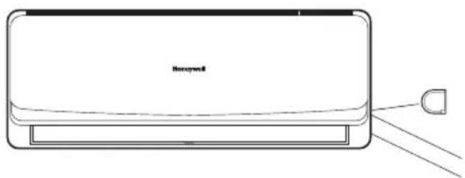
Route of Pipeline
- Depending on the position of the unit, the piping may be routed sideways from the left or the right (Fig 1), or vertically from the back (Fig 2) (depending on the pipe length of the indoor unit). In the case of sideway routing, cut off the outlet cutting stock of the opposite side.
natural_image
Line drawing of a hexagonal air conditioner unit with a D-shaped connector (no text or symbols)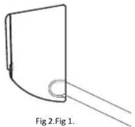
natural_image
Simple line drawing of a curved object with a circular end, labeled Fig 2.Fig 1 (no text or symbols on the object itself)Drainpipe Connection
- Remove the mountings and pull the indoor unit pipe out of the housing.
- Connect the connecting pipe to the indoor unit:
- Aim at the pipe center, tighten the taper nut with fingers, and then tighten the taper nut with a torque wrench. The torque used is shown on the table below.
| Tightening Torque Table | |
| Pipe Size Torque | |
| (1/4)" 15~25 | |
| (3/8)" 35~40 | |
| (1/2)" 45~60 | |
| (5/8)" 73~78 | |
| (3/4)" 75~80 |
INSTALLATION: INDOOR UNIT
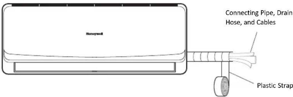
Wrap the Piping
- Use the insulation sleeve to wrap the joint part of the indoor unit and the connection pipe. Then use the insulating material to pack and seal insulation pipe, to prevent generation of condensate water on the joint part.
- Connect the water outlet with drainpipes, and make the connection pipe, cables, and the drain hose straight.
- Use plastic cable ties to wrap the connecting pipes, cables and drain hose. Run the pipe sloping downward.
Fixing the Indoor Unit
- Hang the indoor unit on the peg board and move the unit from left to right to ensure that the hook is properly positioned in the peg board.
- Push toward the lower left side and the upper right side of the unit toward the peg board, until the hook is embedded in the slot and makes a "click" sound.
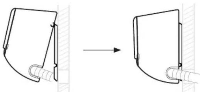
natural_image
Diagram showing a mechanical assembly before and after transformation, with no visible text or symbols.INSTALLATION: INDOOR UNIT
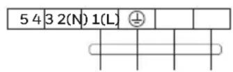
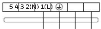
Wiring Diagram
- If the air conditioner is provided with an interconnection cord, the wiring of the indoor unit is connected in the factory, there is no need of connection.
- If the interconnection cord is not provided, connection is needed in accordance with the wiring diagram.
Constant Speed Variable Speed
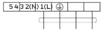
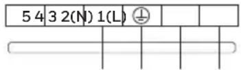
Connector
If there is a connector, connect it directly.
NOTE:
- This manual usually includes the wiring mode for the different kind of A/C. We cannot exclude the possibility that some special type of wiring diagrams are not included.
- The diagrams are for reference only. If the entity is different with this wiring diagram, please refer to the detailed wiring diagram adhered on the unit.
INSTALLATION: OUTDOOR UNIT
Clearance Drawing for Outside Installation
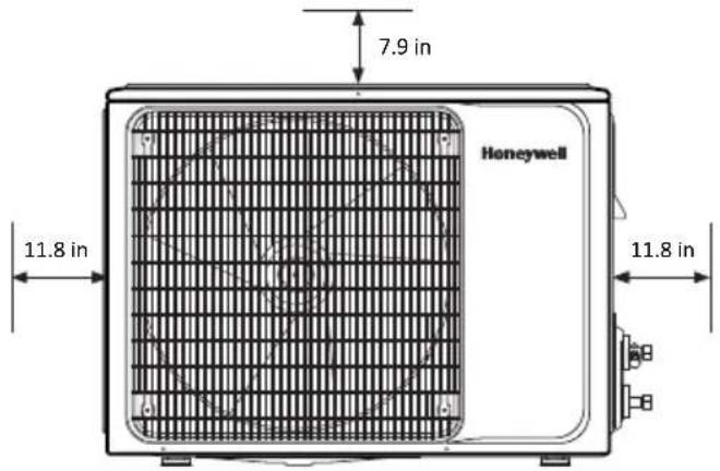
NOTE: All measurements should be no less than posted from obstructions.
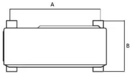
Unit Mounting Dimensions
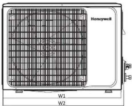
NOTE: Technique to measure distance does not change between unit design versions.
| Installation Outdoor Unit Bolt | |||
| Unit BTU | Outdoor Unit Size W1(W2)*H*D (in. " ) | A (in. ") | B (in. " ) |
| 12K BTU | 28.74(30.4)*21.46*11.22 21.1 10.9 | ||
| 18K BTU | 30.90(33.5)*21.90*11.8 21.1 12.7 | ||
| 24K BTU | 32.48(34.3)*25.79*12.2 24.6 13.7 | ||
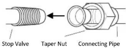
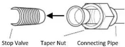
Install the Connection Pipe
- Aim the counter-bore of the connecting pipe at the stop valve and tighten the taper nut with fingers. Then tighten the taper nut with a torque wrench to the correct specification mentioned on pg. 10.
- When extending the pipe, an extra amount of refrigerant must be added so that the operation and performance of the air conditioner will not be compromised.
NOTE: This table is for reference only.
| Piping Length | Amount of Refrigerant to be Added |
| ≤ 16.4ft. | Not Needed |
| 16.4ft. - 49.2ft. | CC ≤ 12000 BTU 20g/m |
| CC ≥ 18000 BTU 30g/m |
INSTALLATION: OUTDOOR UNIT
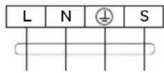
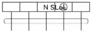
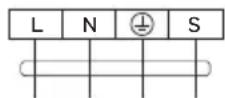
Wiring Connection
- Loosen the screws and remove the E-parts cover from the unit.
- Connect the cables to the corresponding terminals of the terminal board of the outdoor unit (see the wiring diagram), and if there are signals connected to the plug, just create a butt joint.
- Ground Wire: Remove the grounding screw out of the electric bracket, cover the grounding wire end onto the grounding screw and screw it into the grounding hole.
- Fix the cable reliably with fasteners (Pressing board).
- Put the E-parts cover back in its original place and fasten it with screws.
Wiring Diagram
Constant Speed Variable Speed
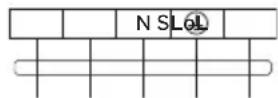
Connector
If there is a connector, connect it directly.
NOTE:
- This manual usually includes the wiring mode for the different kind of A/C. It is possible that some special type of wiring diagrams are not included.
- The diagrams are for reference only. If the entity is different with this wiring diagram, please refer to the detailed wiring diagram adhered on the purchased unit.
INSTALLATION: OUTDOOR UNIT
Expelling the Air
Outdoor Unit Refrigerant Discharging Method:
•After the pipe side connection is complete, proceed as follows.
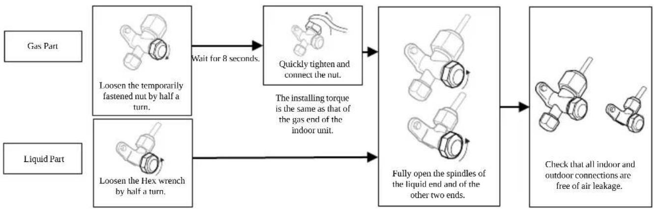
flowchart
graph LR
    A["Gas Part"] --> B["Loosen the temporarily fastened nut by half a turn."]
    C["Liquid Part"] --> D["Loosen the Hex wrench by half a turn."]
    B --> E["Wait for 8 seconds."]
    D --> E
    E --> F["Quickly tighten and connect the nut."]
    F --> G["The installing torque is the same as that of the gas end of the indoor unit."]
    G --> H["Fully open the spindles of the liquid end and of the other two ends."]
    H --> I["Check that all indoor and outdoor connections are free of air leakage."]
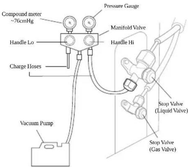
Vacuum Pumping Method:
(R410A refrigerant evacuation must use the Vacuum Pumping Method)
- Before working on the air conditioner, remove the cover of the stop valve (gas and liquid valves) and be sure to retighten afterward. This is done to prevent potential air leakage.
- To prevent air leakage, tighten all the flare tube connecting nuts.
- Connect the stop valve, charge hose, manifold valve, and vacuum pump.
- Fully open the “Handle Lo” of the manifold valve and apply the vacuum for at least 15 minutes. Check that the compound vacuum gauge reads -0.1 Mpa (-76cmHg).
- After applying the vacuum, fully open the stop valve with a hex wrench.
- Check that both indoor and outdoor connections are free of air leakage.
INSTALLATION: OUTDOOR UNIT
Outdoor Condensation Drainage
- When the unit is heating, the condensing water and defrosting water can go through the drain elbow.
Installation:
- There are three drain holes to choose from. Install the outdoor drain elbow in one of the 25 mm hole on the base plate and join the drain hose to the elbow. Plug any unused holes. This will provide a proper outlet for any wastewater collecting in the outside unit.
NOTE: Drain elbow is not included.
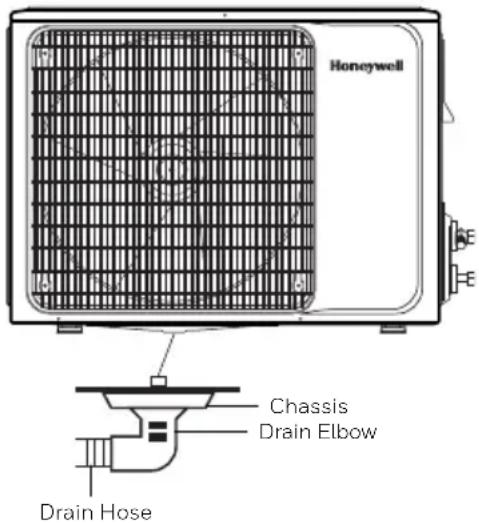
NOTE: Drain holes are in the same location between outdoor unit versions.
CHECK AFTER INSTALLATION
Electrical Safety Check
- If the supply voltage is as required.
- If there is any faulty or misconnection in each of the power, signal and grounding wires.
- If the grounding wire of the air conditioner is securely grounded.
Installation Safety Check
- If the installation is secure.
- If the water drain is smooth.
- If the wiring and piping are correctly installed.
- Check that no foreign matter or tools are left inside the unit.
Leak Test of the Refrigerant
Depending on the installation method, the following methods may be used to check for suspect leak, on areas such as the four connections of the outdoor unit and the cores of the cut-off valves and t-valves:
- Bubble Method: Spray a uniform layer of soapy water over the suspected leak spot and observe carefully for bubbles.
- Instrument Method: Checking for leaks by pointing the probe of the leak detector according to the instruction to the suspect points of the leak.
Temperature Range Conditions
- Outside the temperature range provided in following table, the air conditioner may shut down.
| Cooling | Outdoor | >109.4°F |
| >125.6°F | ||
| Indoor < 64.4°F | ||
| Heating | Outdoor | >75.2°F |
| >19.4°F | ||
| Indoor >80.6°F | ||
- When the temperature is too high, the air conditioner may activate the automatic protection device and shut the unit down.
- When the temperature is too low, the heat exchanger may freeze, leading to water leakage or another malfunction.
- In long-term cooling or dehumidification with a relative humidity of above 80% (doors and windows are open), there may be water condensation near the air outlet.
Notes for Heating
- The fan of the indoor unit will not run immediately after cooling to prevent expelling cold air.
- When it is cold and wet outside, the outdoor unit will develop frost over the heat exchanger which will compromise the heating capacity. This is when the air conditioner will start to defrost.
- During defrost, the air conditioner will stop heating for about 5-12 minutes.
•Vapor may come out from the outdoor unit during defrost. This is not a malfunction, but a result of a fast defrost.
• Heating will resume after the defrost is complete.
Notes for Turning Off Unit
- When the air conditioner is turned off, the main controller will automatically decide whether to stop immediately or after running for a short period of time with lower air speed.
NOTICES FOR USE
Emergency Operation
- If the remote controller is lost or broken, use the force switch button to operate the air conditioner.
- If this button is pushed with the unit OFF, the air conditioner will operate in AUTO mode.
- If this button is pushed with the unit ON, the air conditioner will stop running.
- The force switch is located on the right side of the unit and is in a tight space. User may need a thin object such as a screwdriver to push the button.
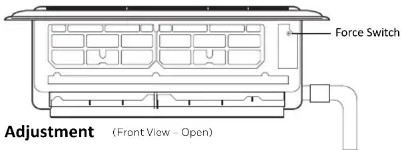
Airflow Direction Adjustment
- Use up-down swing and left-right swing buttons on the remote controller to adjust the airflow direction. Refer to the operation manual of the remote controller for details.
TEST OPERATION
Test Operation Preparation
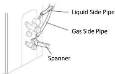
- Verify that all piping and connection cables are well connected.
- Confirm that the values at the gas side the liquid-side are fully open.
- Connect the power cord of the outdoor unit to an independent power socket.
• Install the batteries in the remote control.
Test Operation Method
- Turn on the power and push the ON/OFF switch button of the remote controller to start the air conditioner.
- Select COOL, HEAT, SWING and other operation modes with the remote controller and see if the operation is ok.
Specific Caution
- Open the front panel of the indoor unit.
- The connector can not touch the terminal board.
SAFETY INSTRUCTIONS – UNIT OPERATION
Always be careful when using the machine. To reduce the risk of fire, electrical shock, or other injuries, keep these safety considerations in mind when installing, using, and maintaining your machine.

CAUTION
- Do not let the remote controller drop or fall.
- Do not let the remote controller get wet.
- Do not expose the remote controller directly to the sunlight or excessive heat.
- If the remote controller does not work normally, remove the batteries for 30 seconds before you reinstall them. If that doesn't work, replace the batteries.
- When replacing the batteries, do not mix new batteries with old ones or mix batteries of different types.
- If the remote controller is not used for a long period of time, remove the batteries first to avoid the risk of leakage that may damage the remote controller.
- Properly dispose of discarded batteries.
REMOTE CONTROL FUNCTIONS
NOTE:
The remote controller displays all symbols during power-on and only those corresponding to operation the rest of the time.
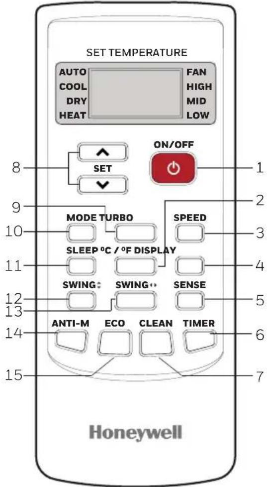
1. ON / OFF
- Press this button to turn on/off the unit.
- This will clear the existing timer and sleep settings.
2. °C / °F
- Press this button to set the temperature display to Fahrenheit, which is displayed by default in Celsius. The “°C” will not be displayed on the LCD.
- Press this button again to restore the temperature display to Celsius.
3. SPEED
- Press this button, you can select the fan speed as follows: Low -> Mid -> High -> Auto
NOTE: AUTO air speed is not available in FAN mode.
4. DISPLAY
- Press this button to turn on/off the display. This is for the convenience of users who are uncomfortable sleeping with the backlight on.
5. SENSE
- Press this button to set the temperature display on the remote controller to the temperature around the remote. Press this button again to set it to preset temperature.
REMOTE CONTROL FUNCTIONS
6. TIMER
- With the unit ON, press this button to set OFF timer, with it OFF, press to set ON timer.
- Press this button once, an “ON (OFF)” will flash. Press “^” or “▼” to set the number of hours in which the unit will be turned ON/OFF, with an interval of 0.5 hour if less than 10 hours, or 1 hour if longer than 10 hours, and a range of 0.5-24 hours.
- Press it again to confirm the setting, the "ON (OFF)" will stop flashing.
- If the timer button is not pressed longer than 10 seconds after the “ON (OFF)” start flashing, the timer setting will be exited.
- If a timer setting is confirmed, pressing this button again will cancel it.
7. CLEAN
- Press this button with the unit OFF, the remote controller will display “CL” and the unit will automatically clean dust off the evaporator and dry it. This will increase the cooling and heating efficiency.
- The Clean function runs for approximately 30 minutes, if the unit is turned on with the remote controller or this button is pressed again, the Clean function will be deactivated.
8. ^ OR v
Each time the “ ^A ” is pressed, the temperature setting will increase by 1°F and each time the “V” is pressed, it will decrease by 1°F. The temperature range is 60°F - 90°F.
NOTE: The temperature cannot be set in AUTO or FAN mode, thus these two buttons are not functional.
9. TURBO
- Press this button only in COOL or HEAT mode to set TURBO on or off to speed the cooling or heating.
- When TURBO is on, the air speed is HIGH.
- When TURBO is off, the air speed will restore to previous status.
10. MODE
- Press this button, you can select the running mode as follows: AUTO -> COOL -> DRY -> HEAT -> FAN
REMOTE CONTROL FUNCTIONS
11. SLEEP
- Press this button to enter SLEEP mode, which the unit will exit after 10 hours of continuous operation and restore to the previous status.
NOTE: The SLEEP function cannot be activated in FAN mode.
12. SWING (Vertically)
- Press this button to activate up/down swing and press it again to reset the swing position.
13. SWING (Horizontally)
- Press this button to activate left/right swing and press it again to reset the swing position.
14. ANTI-M
- The Anti-M functions when the unit is turned off with the remote controller in COOL, DRY or AUTO mode. It will operate in HEAT mode (FAN mode for cool only units), with the internal fan running with weak flow for 3 minutes before stop, to remove the moisture within the evaporator so as to prevent it from giving off any bad smells from mold.
- This function is not set in the factory. It may be set or cancelled any time as follows: With the unit ON, press “Anti-M” button once, the buzzer will sound 5 times, indicating this function is set. Once set, this function will remain active except when the unit is powered off or until it is cancelled.
•To cancel Anti-M:
- Power off the unit.
- With both the unit and the remote controller OFF, point the remote controller at the unit and press this button once, the buzzer will sound 3 times, indicating this function is canceled.
NOTE:
- With Anti-M activated, do not turn the unit ON again before it is fully OFF.
- Anti-M function will not function when the OFF timer is set.
15. ECO
- If this button is pressed in COOL mode, the unit will enter ECO mode which has the lowest electricity consumption and exit it automatically 8 hours after.
- Changing modes or turning off the remote controller will automatically cancel the ECO function.
- Press ECO button in ECO mode to exit this mode.
AIR CONDITIONER OPERATION
Install Batteries
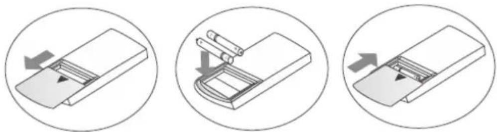
- Install the batteries included with the unit. (Triple A) and position the batteries to the right electric poles (+ and -).
- Put back on the cover.
Automatic Operation Mode
- Press the "MODE" button, select the automatic operation mode.
- By pressing the "SPEED" button, you can select the fan speed from LOW, MID, HIGH, AUTO.
- Press the "ON/OFF" button, the air conditioner starts to operate.
- Press the "ON/OFF" button again, the air conditioner stops.
NOTE: In the fan operation mode, the temperature settings is non-effective.
Cooling/Heating Operation Mode
- Press the "MODE" button, select the Cooling or Heating operation mode.
- By pressing the “^” or “V” button, you can set the temperature. The display changes as you press the button.
- By pressing the "SPEED" button, you can select the fan speed from LOW, MID, HIGH, AUTO.
- Press the "ON/OFF" button, the air conditioner starts to operate.
- Press the "ON/OFF" button again, the air conditioner stops.
AIR CONDITIONER OPERATION
Fan Operation Mode
- Press the "MODE" button, select the fan operation mode.
- By pressing the "SPEED" button, you can select the fan speed from LOW, MID, HIGH.
- Press the "ON/OFF" button, the air conditioner starts to operate.
- Press the "ON/OFF" button again, the air conditioner stops.
NOTE: In the fan operation mode, the temperature settings is non-effective.
Drying Operation Mode
- Press the "MODE" button, select the drying operation mode.
- By pressing the “Λ” or “V” button, you can set the temperature, the display changes as you touch the button.
- By pressing the "SPEED" button, you can select the fan speed from LOW, MID, HIGH, AUTO.
- Press the "ON/OFF" button, the air conditioner starts to operate.
- Press the "ON/OFF" button again, the air conditioner stops.
Backlight Function
- The remote controller has a backlight which can be turned on by pressing any button for the convenience of operation in darkness. The backlight will be automatically turned off if there is no operation within 10 seconds.
MACHINE MAINTENANCE
WARNING:
- Before cleaning the air conditioner, it must be shut down and the electricity must be cut off for more than 5 minutes, otherwise there is a risk of electric shock. Do not wet the air conditioner, which can cause an electric shock. Make sure not to rinse the air conditioner with water under any circumstances.
- Do not use liquid or corrosive cleaning agents when wiping the air conditioner. Do not sprinkle water or any other liquid on the unit.
- Harsh liquids such as thinner or gasoline will damage the air conditioner housing, therefore please clean the housing of the air conditioner with a soft dry cloth or a damp cloth moistened with a gentle detergent.
Cleaning the Indoor Unit Panel
- When the panel of the indoor unit is contaminated, clean it gently with a wrung towel using warm water (below 113^ F) and do not remove the panel while cleaning.
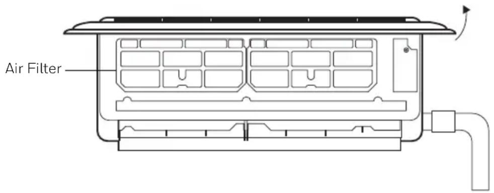
Clean the Air Filter
- Use both hands to open the panel upwards towards the ceiling.
- Release the air filter from the slot and remove it.
- Use a vacuum cleaner or water to rinse the filter, and if the filter is very dirty (ex. grease), clean it with warm water (below 113^ F) with mild detergent (neutral pH) dissolved in, and then put the filter in the shade to dry.
- Reinstall the dried filter in reverse order of removal, then cover and lock the panel.
MACHINE MAINTENANCE
Check Before Use
- Check whether all the air inlets and outlets of the units are unblocked.
- Check whether there is blocking in the water outlet of the drainpipe, and immediately clean it up if any.
- Check the ground wire is reliably grounded.
- Check whether the remote control batteries are installed, and whether the power is sufficient.
- Check whether there is damage in the mounting bracket of the outdoor unit, and if any, please contact a qualified service technician.
Maintain After Use
- Cut off the power source of the air conditioner, turn off the circuit breaker and remove the batteries from the remote control.
- Clean the filter and the unit body.
- Remove the dust and debris from the outdoor unit.
- Check whether there is damage in the mounting bracket of the outdoor unit, and if any, please contact a qualified service technician.
Immediately stop all operations and cut off the power supply, contact a qualified service technician locally in the following situations:
- A loud noise is heard, or an unpleasant odor is emitted during operation.
•Power plug/cord are abnormally hot.
•Air switch (fuse) often trips.
TROUBLESHOOTING
In case of problems, first turn off the air conditioner and disconnect from the source of electricity.
| Symptom Solutions | |
| Air conditioner can not operate at all | Has the power been shut down?Is the wiring loose?Is voltage too high or too low? (measured by professionals)Does it reach the set time for start up?Does the circuit protection device trip? |
| Remote controller is not responding | Is the remote controller out of effective distance to the indoor unit?Are there any obstructions between the controller and the signal receptor?Is the battery exhausted? |
| Cooling/Heating efficiency is not good | Is the setting temperature suitable?Is the air inlet or outlet obstructed?Is indoor fan speed set at low speed?Is there any heat source in your room?Is the air filter dirty? |
| Indoor unit does not operate immediately when the air conditioner is restarted | If the air conditioner is turned on immediately after it is turned off, the protective delay switch will delay the operation for 3 to 5 minutes. |
| There is an unusual smell blowing from the outlet after operation is started | The air conditioner itself does not have undesirable odor. If there is odor, it may be due to accumulation of the odor in the environment. Please clean the air filter or activate the cleaning function. |
| There is sound of running water during the running of air conditioner | Sometimes the “hissing” sound of running water can be heard. This is the sound of the flow of the refrigerant -- not a malfunction. |
| A slight “click” sound is heard at the of start-up or shut-down | Due to temperature changes, panel, and other parts will swell, causing the sound of friction. This is normal, not a fault. |
| During the cooling operation, the indoor unit outlet sometimes will blow out mist | This is because the indoor air is cooled rapidly. After it runs for some time, the indoor temperature and humidity will be reduced, and the mist will disappear |
NOTE: Do not attempt to repair the unit by yourself. For repairs, contact the company that installed the unit.
For all replacements, contact Royal Sovereign Customer Service at +1 855-687-2223 or supportusa@honeywelldispensers.com.
TWO YEARS LIMITED WARRANTY
Royal Sovereign International, Inc. warranties this product to be free from defects in material and workmanship for a period of two (2) years. This warranty is extended to the original purchaser only as outlined below:
Parts: Replacement of defective parts for 2 years from the date of customer purchase.
Compressor: 3-year warranty from the date of customer purchase. Royal Sovereign will supply a replacement compressor (parts only), free of charge.
Labor: NO LABOR. The original owner is solely responsible for all labor costs. This limited warranty does NOT include labor or other costs incurred for service, maintenance, repair, removal, replacement, or installation.
This warranty only covers products that are properly installed, properly maintained, and properly operated in accordance with the instructions provided. This limited warranty does not cover any failures or operating difficulties due to normal wear and tear, accident, abuse, misuse, alteration, misapplication, improper installation, or improper maintenance and service by you or any third party.
To request a return, please contact +1 855-687-2223 or supportusa@honeywelldispensers.com. All transportation costs for the return of damaged product or parts will be the responsibility of the purchaser. Return defective product, in original packaging, to the address below.
Royal Sovereign International, Inc. requires reasonable proof of your date of purchase from an authorized retailer or distributor. Therefore, you should keep your receipt, invoice, or canceled check from the original purchase. The limited warranty shall be limited to the repair or replacement of parts which prove defective under normal use and service within the warranty period.
Royal Sovereign International, Inc. (and its affiliated companies) SHALL HAVE NO LIABILITY WHATSOEVER TO PURCHASER OR ANY THIRD PARTY FOR ANY SPECIAL, INDIRECT, PUNITIVE, INCIDENTAL, OR CONSEQUENTIAL DAMAGES. Some states do not allow the exclusion or limitation of incidental or consequential damages so the above exclusion and limitations may not apply to you.
For product support and warranty questions, please visit us atwww.honeywelldispensers.com
ROYAL SOVEREIGN INTERNATIONAL, INC.
2 Volvo Dr., Rockleigh, NJ 07647 USA
TEL:+1 855-687-2223
Email: supportusa@honeywelldispensers.com
The Honeywell Trademark is used under license from Honeywell International Inc.
Honeywell International Inc. makes
no representations or warranties with respect to this product.
This product is manufactured by Royal Sovereign International.