
CCTVPROM23W - Surveillance Camera EtiamPro - Free user manual and instructions
Find the device manual for free CCTVPROM23W EtiamPro in PDF.

| Product Type | Digital Video Recorder (DVR) for Surveillance |
| Brand | EtiamPro |
| Model | CCTVPROM23W |
| Video Input | BNC (Turbo HD and analog), up to 16 channels (varies by model) |
| Audio Input | RCA (audio in, line in) |
| Video Output | BNC, VGA, HDMI |
| Audio Output | RCA |
| Network Interface | RJ-45 10/100/1000 Mbps (self-adaptive) |
| Hard Drive Support | Internal HDD (SATA), eSATA for expansion |
| Power Supply | 100-240 VAC, 48 VDC, or 12 VDC (depending on model) |
| Power Consumption | < 30 W (typical, without HDD) |
| Dimensions (W x D x H) | Approx. 300 x 250 x 50 mm (without rack ears) |
| Weight | Approx. 2.5 kg (without HDD) |
| Operating Temperature | -10°C to 55°C (14°F to 131°F) |
| Operating Humidity | 10% to 90% (non-condensing) |
| Certifications | FCC (Class A), CE, ICES-003 |
| Password Protection | Admin password, unlock pattern, lockout after failed attempts |
| Remote Access | Via web browser, Guarding Vision app (iOS/Android) |
| HDD Installation | Fix-on-bottom, bracket, or front panel plug-pull |
| Recording Modes | Manual, continuous, motion detection, alarm triggered |
| Playback | Multiple channels simultaneous, calendar search |
| Alarm Interfaces | Alarm input/output (on rear panel) |
| RS-485/RS-232 | PTZ control and serial configuration |
Frequently Asked Questions - CCTVPROM23W EtiamPro
User questions about CCTVPROM23W EtiamPro
0 question about this device. Answer the ones you know or ask your own.
Ask a new question about this device
Download the instructions for your Surveillance Camera in PDF format for free! Find your manual CCTVPROM23W - EtiamPro and take your electronic device back in hand. On this page are published all the documents necessary for the use of your device. CCTVPROM23W by EtiamPro.
USER MANUAL CCTVPROM23W EtiamPro


Regulatory Information
FCC Information
Please take attention that changes or modification not expressly approved by the party responsible for compliance could void the user's authority to operate the equipment.
FCC compliance: This equipment has been tested and found to comply with the limits for a Class A digital device, pursuant to part 15 of the FCC Rules. These limits are designed to provide reasonable protection against harmful interference when the equipment is operated in a commercial environment. This equipment generates, uses, and can radiate radio frequency energy and, if not installed and used in accordance with the instruction manual, may cause harmful interference to radio communications. Operation of this equipment in a residential area is likely to cause harmful interference in which case the user will be required to correct the interference at his own expense.
FCC Conditions
This device complies with part 15 of the FCC Rules. Operation is subject to the following two conditions:
-
This device may not cause harmful interference.
-
This device must accept any interference received, including interference that may cause undesired operation.
EU Conformity Statement

This product and - if applicable - the supplied accessories too are marked with "CE" and comply therefore with the applicable harmonized European standards listed under the EMC Directive 2014/30/EU, the LVD Directive 2014/35/EU, the RoHS Directive 2011/65/EU.
2012/19/EU (WEEE directive): Products marked with this symbol cannot be disposed of as unsorted municipal waste in the European Union. For proper recycling, return this product to your local supplier upon the purchase of equivalent new equipment, or dispose of it at designated collection points.
2006/66/EC (battery directive): This product contains a battery that cannot be disposed of as unsorted municipal waste in the European Union. See the product documentation for specific battery information. The battery is marked with this symbol, which may include lettering to indicate cadmium (Cd), lead (Pb), or mercury (Hg). For proper recycling, return the battery to your supplier or to a designated collection point. For more information see:
www.recyclethis.info
Industry Canada ICES-003 Compliance
This device meets the CAN ICES-3 (A)/NMB-3(A) standards requirements.
Trademarks Acknowledgement
Trademarks and logos mentioned are the properties of their respective owners.

The terms HDMI and HDMI High-Definition Multimedia Interface, and the HDMI Logo are
trademarks or registered trademarks of HDMI Licensing Administrator, Inc. in the United States and other countries.
Symbol Conventions
The symbols that may be found in this document are defined as follows.
| Symbol | Description |
 NOTE NOTE | Provides additional information to emphasize or supplement important points of the main text. |
 WARNING WARNING | Indicates a potentially hazardous situation, which if not avoided, could result in equipment damage, data loss, performance degradation, or unexpected results. |
 DANGER DANGER | Indicates a hazard with a high level of risk, which if not avoided, will result in death or serious injury. |
Safety Instructions
- Proper configuration of all passwords and other security settings is the responsibility of the installer and/or end-user.
- Firmly connect the plug to the power socket. Do not connect several devices to one power adapter. Power off the device before connecting and disconnecting accessories and peripherals.
● Shock hazard! Disconnect all power sources before maintenance.
● The equipment must be connected to an earthed mains socket-outlet.
● The socket-outlet shall be installed near the equipment and shall be easily accessible.
● indicates hazardous live and the external wiring connected to the terminals requires installation by an instructed person. - Never place the equipment in an unstable location. The equipment may fall, causing serious personal injury or death.
- Input voltage should meet the SELV (Safety Extra Low Voltage) and the LPS (Limited Power Source) according to the IEC60950-1.
● High touch current! Connect to earth before connecting to the power supply. - If smoke, odor or noise rise from the device, turn off the power at once and unplug the power cable, and then please contact the service center.
- Use the device in conjunction with an UPS, and use factory recommended HDD if possible.
- This product contains a coin/button cell battery. If the battery is swallowed, it can cause severe internal burns in just 2 hours and can lead to death.
● This equipment is not suitable for use in locations where children are likely to be present.
● CAUTION: Risk of explosion if the battery is replaced by an incorrect type. - Improper replacement of the battery with an incorrect type may defeat a safeguard (for example, in the case of some lithium battery types).
- Do not dispose of the battery into fire or a hot oven, or mechanically crush or cut the battery, which may result in an explosion.
-
Do not leave the battery in an extremely high temperature surrounding environment, which may result in an explosion or the leakage of flammable liquid or gas.
-
Do not subject the battery to extremely low air pressure, which may result in an explosion or the leakage of flammable liquid or gas.
- Dispose of used batteries according to the instructions
- Keep body parts away from fan blades and motors. Disconnect the power source during servicing.
Preventive and Cautionary Tips
Before connecting and operating your device, please be advised of the following tips:
- The device is designed for indoor use only. Install it in a well-ventilated, dust-free environment without liquids.
- Ensure recorder is properly secured to a rack or shelf. Major shocks or jolts to the recorder as a result of dropping it may cause damage to the sensitive electronics within the recorder.
● The equipment shall not be exposed to dripping or splashing and that no objects filled with liquids shall be placed on the equipment, such as vases. - No naked flame sources, such as lighted candles, should be placed on the equipment.
- The ventilation should not be impeded by covering the ventilation openings with items, such as newspapers, tablecloths, curtains, etc. The openings shall never be blocked by placing the equipment on a bed, sofa, rug or other similar surface.
- For certain models, ensure correct wiring of the terminals for connection to an AC mains supply.
- For certain models, the equipment has been designed, when required, modified for connection to an IT power distribution system.
- Use only power supplies listed in the user manual or user instruction.
Chapter 1 Rear Panel Interfaces Description
The rear panel interfaces vary with different models. Refer to Table 1-1 for the common interfaces description. Table 1-1 Common Interfaces Description of Rear Panel
| Item | Description | Item | Description |
| VIDEO IN | BNC interface for Turbo HD and analog video input | VIDEO OUT | BNC connector for video output |
| AUDIO IN | RCA connector for audio input | AUDIO OUT | RCA connector for audio output |
| LINE IN | RCA connector for two-way audio input | USB | Universal Serial Bus (USB) interface for mouse, keyboard, or USB flash drive |
| VGA | DB15 connector for local video output and menu display | HDMI | HDMI interface for video output |
| RS-485 | RS-485 serial interface for pan/tilt unit, speed dome, etc | RS-232 | RS-232 interface for parameter configuration, or transparent channel |
| LAN | RJ-45 self-adaptive Ethernet interface | eSATA | Storage and expansion interface for record or backup |
| ALARM IN/OUT | Alarm input/output interface | GND | Ground |
| Power Switch | Switch for turning on/off the device | Power Supply | 100 to 240 VAC, 48 VDC, or 12 VDC power supply, different models vary |
Chapter 2 Installation and Connections
2.1 Device Installation
During installation of the device:
- Use brackets for rack mounting.
- Ensure ample room for audio and video cables.
- When routing cables, ensure the bend radius of the cables are no less than five times of its diameter.
- Allow at least 2 cm (≈0.75 inch) of space among racks mounted devices.
- Ensure the device is grounded.
● Environmental temperature should be within the range of -10\ °C to 55\ °C ( 14\ °F to 131\ °F ).
● Environmental humidity should be within the range of 10% to 90%.
2.2 HDD Installation
Before you start
● Ensure power is disconnected.
● Prepare a factory recommended HDD, and cross screwdriver.
2.2.1 Fix-on-Bottom Installation
Fix-on-bottom installation is applicable when it requires to install the HDD at the internal bottom.
Step 1 Unfasten screws on each panel to remove the device cover. Refer to Figure 2-1.
Step 2 Connect the data cable and power cable. Refer to Figure 2-2.
Step 3 Match HDD screw threads with the reserved holes on the device bottom, and fix HDD with screws. Refer to Figure 2-3.

NOTE
You can repeat the steps above to install other HDDs.
Step 4 Reinstall the device cover and fasten screws.
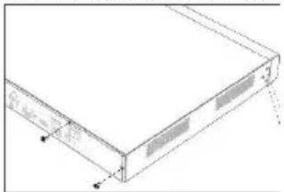
Figure 2-1 Remove Cover
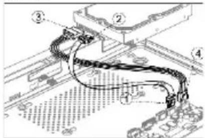
Figure 2-2 Connect Cable
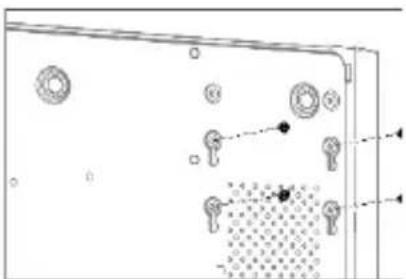
Figure 2-3 Fix HDD
2.2.2 Bracket Installation
Bracket installation is applicable when it requires to remove the device cover and install HDD on the internal bracket.
Step 1 Unfasten screws on the back and push the cover backwards to remove the cover. Refer to Figure 2-4.
Step 2 Fix the HDD on the bracket with screws. Refer to Figure 2-5.

NOTE
Please uninstall the upper layer bracket first before installing HDD on the lower layer bracket.
Step 3 Connect the data cable and power cable. Refer to Figure 2-6.

NOTE
You can repeat the steps above to install other HDDs.
Step 4 Reinstall the device cover and fasten screws.
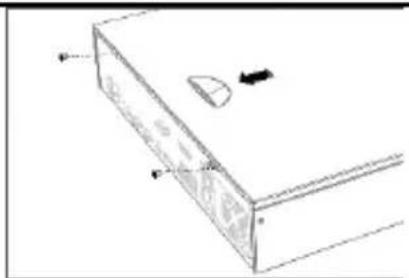
Figure 2-4 Remove Cover

Figure 2-5 Fix HDD
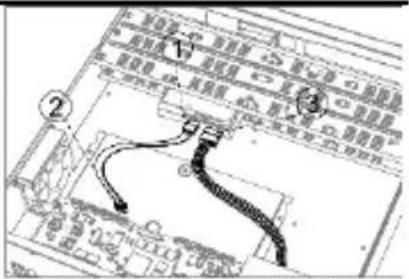
Figure 2-6 Connect Cable
2.2.3 Front Panel Plug-Pull Installation
Front panel plug-pull installation is applicable when it requires to open the device front panel with key.
Step 1 Fix mounting ears to HDD with screws. Refer to Figure 2-7.
Step 2 Use attached key to unlock the front panel, and press buttons on both sides to open the front panel. Refer to Figure 2-8.
Step 3 Insert the HDD until it is firmly fixed. Refer to Figure 2-9

NOTE
You can repeat the steps above to install other HDDs.
Step 4 Close the front panel and lock it with key.

Figure 2-7 Fix Mounting Ear
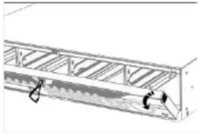
Figure 2-8 Open Front Panel
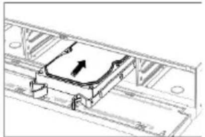
Figure 2-9 Insert HDD
Chapter 3 Menu Operation
3.1 Startup
Proper startup is crucial to expand the life of your device. It is HIGHLY recommended to use an Uninterruptible Power Supply (UPS) with the device.
Step 1 Plug power supply into an electrical outlet.
Step 2 Press the power button (certain models may have power button on the front or rear panel). The device begins to start.
3.2 Activate Your Device
No operation is allowed before activation. For the first-time access, it requires to set an admin password for device activation. You can also activate the device via web browser, SADP or client software.
Step 1 Select a language.
Step 2 Click Next.
Step 3 Enter the same password in Password and Confirm Password.

WARNING
STRONG PASSWORD RECOMMENDED—We highly recommend you create a strong password of your own choosing (Using a minimum of 8 characters, including at least three of the following categories: upper case letters, lower case letters, numbers, and special characters.) in order to increase the security of your product. And we recommend you reset your password regularly, especially in the high security system, resetting the password monthly or weekly can better protect your product.
Step 4 Activate network camera(s) connected to the device.
- Check Use Device Password to use the device password to activate the inactive network cameras(s).
- Enter a password to activate network camera(s).
Step 5(Optional) Set email address for password resetting. When you forget your password, you can reset it by email.
Step 6 Click Activate.
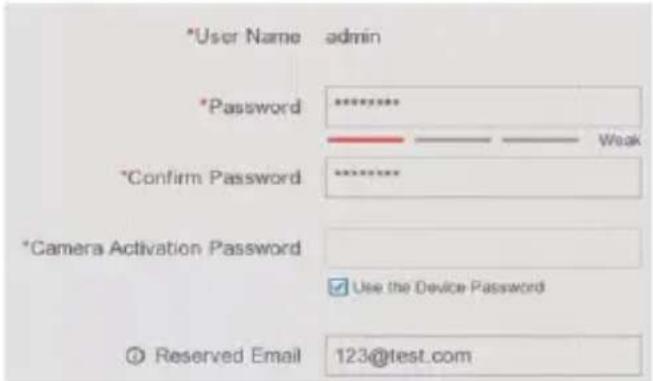
Figure 3-1 Set Admin Password
3.3 Login Unlock Pattern
For the Admin user, you can set the unlock pattern for device login after it is activated.
Step 1 Use mouse to draw a pattern among the 9 dots on the screen. Release the mouse when the pattern is done.

NOTE
● The pattern shall have 4 dots at least.
● Each dot can be connected for once only.
Step 2 Draw the same pattern again to confirm it.

Figure 3-2 Set Unlock Pattern
3.4 User Login
You have to log in to the device before operating the menu and other functions.
Step 1 Select user account.
Step 2 Enter password for the selected user.
Step 3 Click Login.

NOTE
For the admin, if you have entered the wrong password for 7 times, the account will be locked for 60 seconds. For the operator, if you have entered the wrong password for 5 times, the account will be locked for 60 seconds.
3.5 User Logout, Shutdown and Reboot
You can log out of the system, shut down, or reboot the device.
Step 1 Click at the upper-right corner.
Step 2 Click Logout, Shutdown, or Reboot as your desire.
3.6 Add Network Cameras
Before you can get live video or record the video files, you should add network cameras to the device.
Before you start
Ensure the network connection is valid and correct, and the network camera has already been activated.
Step 1 Go to Configuration > Camera > IP Camera.
Step 2Click . +
Step 3 Set the IP camera parameters, including IP address, protocol, management port, etc. You can enable Use Camera Activation Password to use the device password to add the IP camera.
Step 4(Optional) Click Add More to add other IP cameras.
Step 5 Click OK.
Figure 3-3 Add IP Camera
3.7 Network Settings
3.7.1 Configure General Settings
You shall properly configure the network settings before you operate your device over network.
Step 1 Go to Configuration > Network > General.
Step 2 Set the general network parameters.
Step 3 Click Apply.
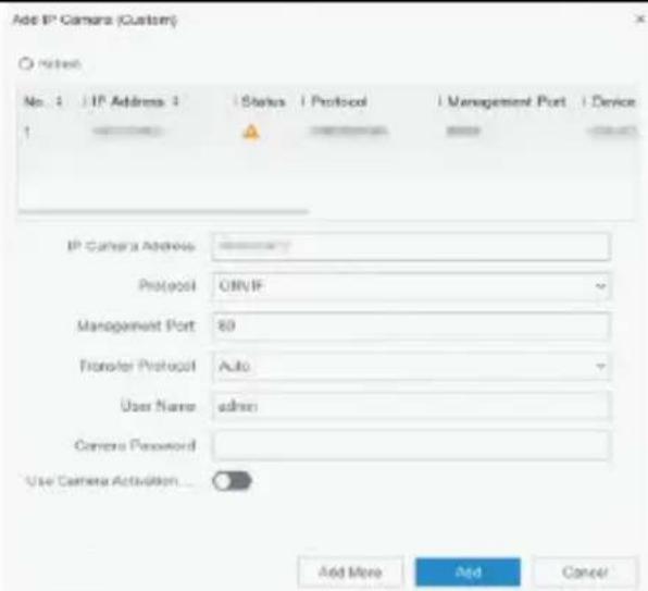
Figure 3-4 Network Settings
3.7.2 Configure Guarding Vision
Guarding Vision provides mobile phone application and platform service to access and manage your connected devices, which enables you to get a convenient remote access to the surveillance system.
Step 1 Go to Configuration > Network > Guarding Vision.
Step 2 Turn on Enable to activate the function and accept service terms. The service terms will pop up.
1) Scan the QR code to read the service terms and privacy statement.
2) Check I have read and agree to Service Terms and Privacy Statement if you agree the service terms and privacy statement.
3) Click OK to save the settings.
Step 3 Click to set verification code.
Step 4 Enable Platform Time Sync, the device will sync time with the platform server instead of NTP server.
Step 5 (Optional) Check Stream Encryption. It requires to enter verification code in remote access and live view after this function is enabled.
Step 6 (Optional) Edit Server IP.
Step 7 Bind your device with a Guarding Vision account.
1) Use a smart phone to scan the QR code, and download Guarding Vision app.
2) Use Guarding Vision to scan the device QR and bind the device.

NOTE
- If the device is already bound with an account, you can click Unbind to unbind with the current account.
- You can also use the QR code in at the upper-left corner to download Guarding Vision and bind your device.
Step 8 Click Apply.
What to do next:
After configuration, you can access and manage your devices via app or website.
3.8 Live View and Record Settings
Live view shows you the video image getting from each camera in real time. The device will automatically enter live mode when powered on. In the live mode, there are icons at the right top of the screen to indicate the status of record and alarm for each channel.
Live View Icons
In the live view mode, there are icons on the screen to indicate the record and alarm status of each channel.
Table 3-1 Description of Live View Icons
| Item | Description | Item | Description |
 | Alarm (video loss, tampering, motion detection, VCA or sensor alarm) | Alarm and Record | |
 | Record (manual record, continuous record, motion detection, VCA or alarm triggered record) |
3.9 Playback
The recorded files on HDD can be played back. Refer to the user manual for details of each playback mode.
Step 1 Go to Playback.
Step 2 Check the channel(s) in the channel list for playback.
Step 3 Double click a date on the calendar.
Step 4(Optional) Use the toolbar in the bottom to control the playing progress.
Step 5(Optional) Select the channel(s) to execute simultaneous playback of multiple channels.
![Normal Event 3 4 5 6 □[D-1] Camera 01 □[D2] IPCamera 02 □[D3] IPCamera 03 □[D4] IPCamera 04 □[D5] IPClose □[D6] DF9G □[D7] IPCamera 07 □[D8] IPCamera 08 □[D9] IPCamera 09 □[D10] IPCamera 10 □[D11] IPCamera 11 2010 Aug B M T W T F S 30 27 18 29 32 35 1 2 3 4 5 6 7 8 9 10 11 12 13 14 15 16 17 18 19 20…](/content/2026/06/1182198/images/4fc16f3340fc9e251245a4cc8df7c6447d3e59d44566f2372991e00a9d7c7a3b.jpg)
Figure 3-5 Playback
Chapter 4 Access by Web Browser

NOTE
The use of the product with Internet access might be under network security risks. For avoidance of any network attacks and information leakage, please strengthen your own protection. If the product does not work properly, please contact with your dealer or the nearest service center.
You can get access to the device via web browser. The following web browsers are supported: Internet Explorer 6.0, Internet Explorer 7.0, Internet Explorer 8.0, Internet Explorer 9.0, Internet Explorer 10.0, Apple Safari, Mozilla Firefox, and Google Chrome. The supported resolutions include 1024*768 and above.
Step 1 Open web browser, enter the IP address of the device and then press Enter.
Step 2 Log in to the device.
- If the device has not been activated, activate the device first by setting the password for the admin user account.
- If the device is already activated, enter the username and password to log in.

Follow the installation prompts to install the plug-in before viewing the live video and managing the device.

NOTE
- You may have to close the web browser to finish the installation of the plug-in.
- After login, you can perform the operation and configuration of the device, including the live view, playback, log search, configuration, etc.


Imported by Velleman Group nv
Legen Heirweg 33, 9890 Gavere, Belgium
www.velleman.eu


- REGULATORY INFORMATION
- FCC INFORMATION
- FCC CONDITIONS
- EU CONFORMITY STATEMENT
- INDUSTRY CANADA ICES-003 COMPLIANCE
- TRADEMARKS ACKNOWLEDGEMENT
- SYMBOL CONVENTIONS
- SAFETY INSTRUCTIONS
- PREVENTIVE AND CAUTIONARY TIPS
- CHAPTER 1 REAR PANEL INTERFACES DESCRIPTION
- CHAPTER 2 INSTALLATION AND CONNECTIONS
- 2.1 DEVICE INSTALLATION
- 2.2 HDD INSTALLATION
- BEFORE YOU START
- 2.2.1 FIX-ON-BOTTOM INSTALLATION
- NOTE
- 2.2.2 BRACKET INSTALLATION
- 2.2.3 FRONT PANEL PLUG-PULL INSTALLATION
- CHAPTER 3 MENU OPERATION
- 3.1 STARTUP
- 3.2 ACTIVATE YOUR DEVICE
- WARNING
- 3.3 LOGIN UNLOCK PATTERN
- 3.4 USER LOGIN
- 3.5 USER LOGOUT, SHUTDOWN AND REBOOT
- 3.6 ADD NETWORK CAMERAS
- 3.7 NETWORK SETTINGS
- 3.7.1 CONFIGURE GENERAL SETTINGS
- 3.7.2 CONFIGURE GUARDING VISION
- WHAT TO DO NEXT
- 3.8 LIVE VIEW AND RECORD SETTINGS
- LIVE VIEW ICONS
- 3.9 PLAYBACK
- CHAPTER 4 ACCESS BY WEB BROWSER
Brand : EtiamPro
Model : CCTVPROM23W
Category : Surveillance Camera