
EDVR208 - Surveillance Camera EtiamPro - Free user manual and instructions
Find the device manual for free EDVR208 EtiamPro in PDF.


| Product Type | Digital Video Recorder |
| Brand | EtiamPro |
| Model | EDVR208 |
| Dimensions | 200 x 150 x 40 mm |
| Weight | 0.5 kg |
| Power Supply | 12V DC, 2A |
| Main Functions | Recording, Playback, Network streaming, Motion detection, Remote access |
| Storage | Up to 2 TB HDD or SSD (not included) |
| Video Inputs | 8 channels BNC |
| Video Output | HDMI, VGA |
| Audio | 1 channel RCA input, 1 channel RCA output |
| Network Interface | 10/100 Ethernet RJ45 |
| USB Ports | 2 x USB 2.0 for backup and mouse |
| Maintenance & Cleaning | Disconnect power before cleaning; use a soft, dry cloth |
| Safety | Use only supplied power adapter; do not expose to moisture |
| Spare Parts & Repairability | Spare parts available: power adapter, remote control, IR receiver; contact EtiamPro support |
| General Information | Compatible with Windows and Mac; supports ONVIF cameras; includes mounting brackets |
Frequently Asked Questions - EDVR208 EtiamPro
User questions about EDVR208 EtiamPro
0 question about this device. Answer the ones you know or ask your own.
Ask a new question about this device
Download the instructions for your Surveillance Camera in PDF format for free! Find your manual EDVR208 - EtiamPro and take your electronic device back in hand. On this page are published all the documents necessary for the use of your device. EDVR208 by EtiamPro.
USER MANUAL EDVR208 EtiamPro
natural_image
Close-up of a black electronic device with a camera lens and control buttons, next to a purple screen displaying '1TB Western Digital' (no readable text on device body)
natural_image
Aerial view of a group of people walking on a paved plaza with modern architecture (no visible text or signage)
natural_image
Silhouettes of pedestrians walking on a city street under bright sunlight, no visible text or signage
Legal Information
About this Manual
The Manual includes instructions for using and managing the Product. Pictures, charts, images and all other information hereinafter are for description and explanation only. The information contained in the Manual is subject to change, without notice, due to firmware updates or other reasons. Please find the latest version of this Manual at the company website Please use this Manual with the guidance and assistance of professionals trained in supporting the Product.
Trademarks Acknowledgement
Trademarks and logos mentioned are the properties of their respective owners.
HDMI™ The terms HDMI and HDMI High-Definition Multimedia Interface, and the HDMI HIGH-DEFINITION MULTIMEDIA INTERFACE Logo are trademarks or registered trademarks of HDMI Licensing Administrator, Inc. in the United States and other countries.
LEGAL DISCLAIMER
TO THE MAXIMUM EXTENT PERMITTED BY APPLICABLE LAW, THIS MANUAL AND THE PRODUCT DESCRIBED, WITH ITS HARDWARE, SOFTWARE AND FIRMWARE, ARE PROVIDED "AS IS" AND "WITH ALL FAULTS AND ERRORS". OUR COMPANY MAKES NO WARRANTIES, EXPRESS OR IMPLIED, INCLUDING WITHOUT LIMITATION, MERCHANTABILITY, SATISFACTORY QUALITY, OR FITNESS FOR A PARTICULAR PURPOSE. THE USE OF THE PRODUCT BY YOU IS AT YOUR OWN RISK. IN NO EVENT WILL OUR COMPANY BE LIABLE TO YOU FOR ANY SPECIAL, CONSEQUENTIAL, INCIDENTAL, OR INDIRECT DAMAGES, INCLUDING, AMONG OTHERS, DAMAGES FOR LOSS OF BUSINESS PROFITS, BUSINESS INTERRUPTION, OR LOSS OF DATA, CORRUPTION OF SYSTEMS, OR LOSS OF DOCUMENTATION, WHETHER BASED ON BREACH OF CONTRACT, TORT (INCLUDING NEGLIGENCE), PRODUCT LIABILITY, OR OTHERWISE, IN CONNECTION WITH THE USE OF THE PRODUCT, EVEN IF OUR COMPANY HAS BEEN ADVISED OF THE POSSIBILITY OF SUCH DAMAGES OR LOSS. YOU ACKNOWLEDGE THAT THE NATURE OF THE INTERNET PROVIDES FOR INHERENT SECURITY RISKS, AND OUR COMPANY SHALL NOT TAKE ANY RESPONSIBILITIES FOR ABNORMAL OPERATION, PRIVACY LEAKAGE OR OTHER DAMAGES RESULTING FROM CYBER-ATTACK, HACKER ATTACK, VIRUS INFECTION, OR OTHER INTERNET SECURITY RISKS; HOWEVER, OUR COMPANY WILL PROVIDE TIMELY TECHNICAL SUPPORT IF REQUIRED.
YOU AGREE TO USE THIS PRODUCT IN COMPLIANCE WITH ALL APPLICABLE LAWS, AND YOU ARE SOLELY RESPONSIBLE FOR ENSURING THAT YOUR USE CONFORMS TO THE APPLICABLE LAW. ESPECIALLY, YOU ARE RESPONSIBLE, FOR USING THIS PRODUCT IN A MANNER THAT DOES NOT INFRINGE ON THE RIGHTS OF THIRD PARTIES, INCLUDING WITHOUT LIMITATION, RIGHTS OF PUBLICITY, INTELLECTUAL PROPERTY RIGHTS, OR DATA PROTECTION AND OTHER PRIVACY RIGHTS. YOU SHALL NOT USE THIS PRODUCT FOR ANY PROHIBITED END-USES, INCLUDING THE DEVELOPMENT OR PRODUCTION OF WEAPONS OF MASS DESTRUCTION, THE DEVELOPMENT OR PRODUCTION OF CHEMICAL OR BIOLOGICAL WEAPONS, ANY ACTIVITIES IN THE CONTEXT RELATED TO ANY NUCLEAR EXPLOSIVE OR UNSAFE NUCLEAR FUEL-CYCLE, OR IN SUPPORT OF HUMAN
RIGHTS ABUSES.
IN THE EVENT OF ANY CONFLICTS BETWEEN THIS MANUAL AND THE APPLICABLE LAW, THE LATER PREVAILS.
Regulatory Information
FCC Information
Please take attention that changes or modification not expressly approved by the party responsible for compliance could void the user's authority to operate the equipment.
FCC compliance: This equipment has been tested and found to comply with the limits for a Class A digital device, pursuant to part 15 of the FCC Rules. These limits are designed to provide reasonable protection against harmful interference when the equipment is operated in a commercial environment. This equipment generates, uses, and can radiate radio frequency energy and, if not installed and used in accordance with the instruction manual, may cause harmful interference to radio communications. Operation of this equipment in a residential area is likely to cause harmful interference in which case the user will be required to correct the interference at his own expense.
FCC Conditions
This device complies with part 15 of the FCC Rules. Operation is subject to the following two conditions:
-
This device may not cause harmful interference.
-
This device must accept any interference received, including interference that may cause undesired operation.
EU Conformity Statement


This product and - if applicable - the supplied accessories too are marked with "CE" and comply therefore with the applicable harmonized European standards listed under the EMC Directive 2014/30/EU, the RoHS Directive 2011/65/EU.
2012/19/EU (WEEE directive): Products marked with this symbol cannot be disposed of as unsorted municipal waste in the European Union. For proper recycling, return this product to your local supplier upon the purchase of equivalent new equipment, or dispose of it at designated collection points. For more information see: http://www.recyclethis.info.
2006/66/EC (battery directive): This product contains a battery that cannot be disposed of as unsorted municipal waste in the European Union. See the product documentation for specific battery information. The battery is marked with this symbol, which may include lettering to indicate cadmium (Cd), lead (Pb), or mercury (Hg). For proper recycling, return the battery to your supplier or to a designated collection point. For more information see: http://www.recyclethis.info.
Industry Canada ICES-003 Compliance
This device meets the CAN ICES-3 (A)/NMB-3(A) standards requirements.
Symbol Conventions
The symbols that may be found in this document are defined as follows.
| Symbol | Description |
 Danger Danger | Indicates a hazardous situation which, if not avoided, will or could result in death or serious injury. |
| [68H2] Caution | Indicates a potentially hazardous situation which, if not avoided, could result in equipment damage, data loss, performance degradation, or unexpected results. |
 Note Note | Provides additional information to emphasize or supplement important points of the main text. |
Safety Instruction
- Proper configuration of all passwords and other security settings is the responsibility of the installer and/or end-user.
- In the use of the product, you must be in strict compliance with the electrical safety regulations of the nation and region.
- Firmly connect the plug to the power socket. Do not connect several devices to one power adapter. Power off the device before connecting and disconnecting accessories and peripherals.
- Shock hazard! Disconnect all power sources before maintenance.
- The equipment must be connected to an earthed mains socket-outlet.
- The socket-outlet shall be installed near the equipment and shall be easily accessible.
- 4 indicates hazardous live and the external wiring connected to the terminals requires installation by an instructed person.
- Never place the equipment in an unstable location. The equipment may fall, causing serious personal injury or death.
- Input voltage should meet the SELV (Safety Extra Low Voltage) and the LPS (Limited Power Source) according to the IEC62368.
- High touch current! Connect to earth before connecting to the power supply.
- If smoke, odor or noise rise from the device, turn off the power at once and unplug the power cable, and then please contact the service center.
- Use the device in conjunction with an UPS, and use factory recommended HDD if possible.
- This product contains a coin/button cell battery. If the battery is swallowed, it can cause severe internal burns in just 2 hours and can lead to death.
- This equipment is not suitable for use in locations where children are likely to be present.
- CAUTION: Risk of explosion if the battery is replaced by an incorrect type.
- Improper replacement of the battery with an incorrect type may defeat a safeguard (for example, in the case of some lithium battery types).
- Do not dispose of the battery into fire or a hot oven, or mechanically crush or cut the battery, which may result in an explosion.
- Do not leave the battery in an extremely high temperature surrounding environment, which may result in an explosion or the leakage of flammable liquid or gas.
- Do not subject the battery to extremely low air pressure, which may result in an explosion or the leakage of flammable liquid or gas.
- Dispose of used batteries according to the instructions.
- Keep body parts away from fan blades and motors. Disconnect the power source during servicing.
- Keep body parts away from motors. Disconnect the power source during servicing.
Preventive and Cautionary Tips
Before connecting and operating your device, please be advised of the following tips:
- The device is designed for indoor use only. Install it in a well-ventilated, dust-free environment without liquids.
- Ensure recorder is properly secured to a rack or shelf. Major shocks or jolts to the recorder as a result of dropping it may cause damage to the sensitive electronics within the recorder.
- The equipment shall not be exposed to dripping or splashing and that no objects filled with liquids shall be placed on the equipment, such as vases.
- No naked flame sources, such as lighted candles, should be placed on the equipment.
- The ventilation should not be impeded by covering the ventilation openings with items, such as newspapers, table-cloths, curtains, etc. The openings shall never be blocked by placing the equipment on a bed, sofa, rug or other similar surface.
- For certain models, ensure correct wiring of the terminals for connection to an AC mains supply.
- For certain models, the equipment has been designed, when required, modified for connection to an IT power distribution system.
-
- identifies the battery holder itself and identifies the positioning of the cell(s) inside the battery holder.
-
- identifies the positive terminal(s) of equipment which is used with, or generates direct current. + identifies the negative terminal(s) of equipment which is used with, or generates direct current.
- Keep a minimum 200 mm (7.87 inch) distance around the equipment for sufficient ventilation.
- For certain models, ensure correct wiring of the terminals for connection to an AC mains supply.
- Use only power supplies listed in the user manual or user instruction.
- The USB port of the equipment is used for connecting to a mouse, keyboard, USB flash drive, or Wi-Fi dongle only.
- Use only power supplies listed in the user manual or user instruction.
- Do not touch the sharp edges or corners.
- When the device is running above 45 °C (113 °F), or its HDD temperature in S.M.A.R.T. exceeds the stated value, please ensure the device is running in a cool environment, or replace HDD(s) to make the HDD temperature in S.M.A.R.T. below the stated value.
Contents
Chapter 1 Startup....1
1.1 Activate Your Device .... 1
1.2 Login....2
1.2.1 Set Unlock Pattern ...... 2
1.2.2 Log in via Unlock Pattern .... 3
1.2.3 Log in via Password ....4
Chapter 2 Live View....5
2.1 GUI Introduction......5
2.2 PTZ Control 6
2.2.1 Configure PTZ Parameter 6
2.2.2 Customize Preset....8
2.2.3 Customize Patrol 8
2.2.4 Customize Pattern....9
Chapter 3 Playback....10
3.1 GUI Introduction....10
3.2 Normal Playback....11
3.3 Smart Playback....11
3.4 Sub-Periods Playback .... 14
3.5 Back up Clip 14
Chapter 4 File Search....15
4.1 Search File....15
4.2 Quick Backup 15
Chapter 5 Configuration (Easy Mode) ...... 16
5.1 System Configuration....16
5.1.1 General 16
5.1.2 User....17
5.1.3 Exception 18
5.2 Network Configuration ...... 19
5.2.1 General 19
5.2.2 Guarding Vision ...... 20
5.2.3 Email 20
5.3 Camera Management....22
5.3.1 Configure Signal Input....22
5.3.2 Network Camera 23
5.3.3 OSD Settings 25
5.3.4 Smart Event ...... 26
5.4 Recording Management....30
5.4.1 Storage Device....30
5.4.2 Configure Recording Schedule....31
5.4.3 Configure Recording Parameter 33
Chapter 6 Configuration (Expert Mode)....35
6.1 System Configuration....35
6.1.1 General 35
6.1.2 Live View....36
6.1.3 User 38
6.2 Network Configuration ...... 38
6.2.1 TCP/IP 38
6.2.2 DDNS 39
6.2.3 NAT 40
6.2.4 Ports (More Settings) 41
6.2.5 Guarding Vision 42
6.2.6 Advanced Settings....42
6.3 Camera Management....43
6.3.1 Configure Signal Input 43
6.3.2 Network Camera 44
6.3.3 Display Settings 48
6.3.4 Privacy Mask....50
6.4 Event Configuration....51
6.4.1 Normal Event....51
6.4.2 Smart Event 56
6.4.3 Configure Arming Schedule 64
6.4.4 Configure Alarm Linkage Action 65
6.5 Recording Management....67
6.5.1 Configure Recording Schedule....67
6.5.2 Configure Recording Parameter 69
6.5.3 Storage Device....70
6.5.4 Configure Storage Mode....71
6.5.5 Advanced Settings....73
6.5.6 Cloud Storage 73
6.6 RS-232 Settings....74
Chapter 7 Maintenance....76
7.1 Restore Default....76
7.2 Search Log....76
7.3 Upgrade 76
7.3.1 Local Upgrade....77
7.3.2 Online Upgrade ...... 77
Chapter 8 Alarm....78
8.1 Set Event Hint....78
8.2 View Alarm in Alarm Center 78
Chapter 9 Web Operation....79
9.1 Introduction....79
9.2 Login....79
9.3 Live View....80
9.4 Playback....81
9.5 Configuration....81
9.6 Log....82
Chapter 10 Appendix....83
10.1 Glossary 83
Chapter 1 Startup
1.1 Activate Your Device
For the first-time access, you need to activate the video recorder by setting an admin password. No operation is allowed before activation. You can also activate the video recorder via web browser, SADP or client software.
Before You Start
Power on your device.
Steps
- Select a language.
- Click Next.
- Input the same password in Password and Confirm Password.
Warning
Strong Password recommended-We highly recommend you create a strong password of your own choosing (Using a minimum of 8 characters, including at least three of the following categories: upper case letters, lower case letters, numbers, and special characters.) in order to increase the security of your product. And we recommend you reset your password regularly, especially in the high security system, resetting the password monthly or weekly can better protect your product.
-
Activate network camera(s) connected to the device.
-
Check Use Device Password as Default to use the device password to activate the inactive network camera(s).
-
Enter a password to activate network camera(s).
-
Optional: Set an email address for password resetting. When you forget your password, you can reset it by email.
1) Check Enable.
2) Enter an email address.
- Click Activate.

Figure 1-1 Activation
1.2 Login
1.2.1 Set Unlock Pattern
Admin user can use the unlock pattern to login. You can configure the unlock pattern after the device is activated.
Steps
- Use the mouse to draw a pattern among the 9 dots on the screen. Release the mouse when the pattern is done.
iNote
-
The pattern shall have 4 dots at least.
• Each dot can be connected for once only. -
Draw the same pattern again to confirm it. When the two patterns match, the pattern is configured successfully.

flowchart
graph TD
    A["Left Node"] --> B["Right Node"]
    B --> C["Left Node"]
    C --> D["Right Node"]
    style A fill:#f9f,stroke:#333
    style B fill:#f9f,stroke:#333
    style C fill:#f9f,stroke:#333
    style D fill:#f9f,stroke:#333
    note bottom of D: Release your finger when done.

flowchart
graph TD
    A[" "] --> B[" "]
    B --> C[" "]
    C --> D[" "]
    style A fill:#fff,stroke:#000
    style B fill:#fff,stroke:#000
    style C fill:#fff,stroke:#000
    style D fill:#fff,stroke:#000
    note bottom of D: Draw pattern again to confirm.
Figure 1-2 Set Unlock Pattern
1.2.2 Log in via Unlock Pattern
Steps
- Right click the mouse on live view interface.

Figure 1-3 Draw the Unlock Pattern
- Draw the pre-defined pattern to unlock to enter the menu operation.

Note
- If you have forgotten your pattern, you click Forgot My Pattern or Switch User to log in via password.
- If you have drawn the wrong pattern for more than 5 times, the system will switch to the normal login mode automatically.
1.2.3 Log in via Password
If your video recorder has logged out, you must login before operating the menu and other functions.
Steps
- Select User Name.

Figure 1-4 Login Interface
- Input password.
- Click Login.

Note
- When you forget the password of the admin, you can click Forgot Password to reset the password.
- If you enter the wrong password 7 times, the current user account will be locked for 60 seconds.
Chapter 2 Live View
2.1 GUI Introduction
- Click Ⓐ to start/stop auto-switch. The screen will automatically switch to the next one.
- Click to start/stop all-day recording.
- Right click a camera, or click to enter full screen mode.
- Double click a camera to view it in single-screen mode. Double click again to exit single-screen mode.
- Change a camera live view screen by dragging it from its screen to the desired screen.
- Scroll up/down to turn to previous/next screen.
- Position the cursor on a camera to show shortcut menu.

Figure 2-1 Shortcut Menu
Table 2-1 Shortcut Menu Description
 |
- In the live view interface, there are icons at the upper-right corner of the screen for each camera, showing the camera recording and alarm status.
Table 2-2 Live View Icon Description
| Icon | Description |
| Alarming (normal event and smart event). | |
| Recording. |
2.2 PTZ Control
2.2.1 Configure PTZ Parameter
You shall configure PTZ parameters before controlling a PTZ camera.
Steps
- Preview a camera in live view and click on shortcut menu.

Figure 2-2 PTZ Settings
- Click PTZ Parameter Settings.

Figure 2-3 PTZ Parameter
- Set the PTZ camera parameters.

Note
- All parameters should be the same as the PTZ camera.
- For the Coaxitron camera/dome connected, you can select the PTZ protocol to UTC (Coaxitron). Ensure the selected protocol is supported by the connected camera/dome.
- The AHD and HDCVI cameras support coaxitron control.
-
Selecting Coaxitron protocol will make other parameters unavailable, including baud rate, data bit, stop bit, parity and flow control.
-
Click OK.
PTZ Control Panel Introduction
Table 2-3 PTZ Panel Description
| Icon | Description | |
 | Direction buttons, and the auto-cycle button. | |
| Speed - + | The speed of the PTZ movement. | |
 | Zoom -/+ . | |
 | Focus -/+ . | |
 | Iris -/+ . | |
2.2.2 Customize Preset
Set a preset location where the PTZ camera would point to when an event occurs.
Steps
- Preview a camera in live view and click on shortcut menu.
- Select a desired preset in preset list.
- Use direction buttons to wheel the camera to required locations. Adjust zoom and focus as your desire.
- Click .
What to do next
Double click a preset in the preset list to call it.
2.2.3 Customize Patrol
Patrol refers to a path consists of a series of presets with designated sequence. It provides dynamic live image for monitoring several presets.
Steps
- Preview a camera in live view and click on shortcut menu.
- Click Patrol.
- Select a desired patrol.
- Click Set.
- Click .+
- Configure key point parameters, such as the key point No., duration of staying for one key point and speed of patrol. The key point is corresponding to the preset. The preset number determines the order at which the PTZ will follow while cycling through the patrol. Duration refers to the time span to stay at the corresponding key point. Speed defines the speed at which the PTZ will move from one key point to the next.
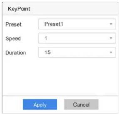
Figure 2-4 Patrol Settings
7. Click Apply.
What to do next
Select a patrol and click Call to call it. The PTZ camera will move according the predefined patrol path.
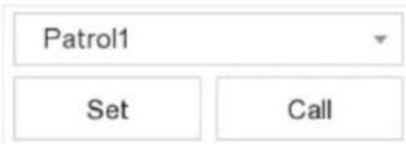
Figure 2-5 Call Preset
2.2.4 Customize Pattern
A pattern records the movement path and dwell time in a certain position. When you call a pattern, the PTZ camera will move according to the recorded path.
Steps
- Preview a camera in live view and click on shortcut menu.
- Click Pattern.
- Select a pattern.
- Click Record.
- Use direction buttons to wheel the camera to required locations. Adjust zoom and focus as your desire.
- Click Stop Recording. The previous PTZ camera moving path is recorded as a pattern.
What to do next
Select a pattern and click Call to call it. The PTZ camera will move according the predefined pattern.
Chapter 3 Playback
3.1 GUI Introduction
Go to Playback.

Figure 3-1 Playback
Table 3-1 Playback Interface Description
| Button | Operation | Button | Operation |
| Switch playback stream. | Clip video. | ||
| 30 s reverse. | 30s forward. | ||
| Reverse playback. | Start playback. | ||
| Speed down. | Speed up. | ||
| Speed. | Full screen. | ||
| Window division. |

Figure 3-2 Timeline
- Position the cursor on the timeline, drag the timeline to position to a certain time.
- Period marked with blue bar contains video. Red bar indicates the video in the period is event video.
- Scroll up/down to zoom out/in timeline.
3.2 Normal Playback
Play back normal videos.
Steps
- Go to Playback.
- Select a camera from the camera list.
- Select a date on the calendar for playback.

The blue triangle at the calendar date corner indicates there are available videos. For example, 22 means video is available. means no video.
- Optional: Position the cursor on playback window to show control bar.

Figure 3-3 Control Bar
Table 3-2 Button Description
| Button | Detection | Button | Detection |
| Add tag. | Zoom in/out playback image. | ||
| Turn on/off audio. | Lock/unlock video. |
3.3 Smart Playback
The smart playback function provides an easy way to get through the less effective information. When you select the smart playback mode, the system will analyze the video containing the
motion detection, line crossing detection, or intrusion detection information.
Before You Start
Configure motion detection, line crossing detection, and intrusion detection rules and detection areas.
Steps
- Go to Playback.
- Click Smart.
- Select a camera.
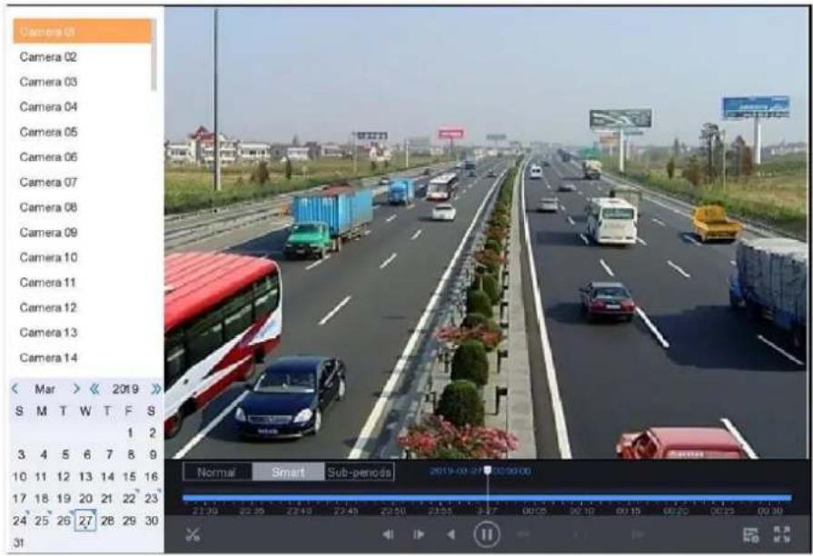
Figure 3-4 Smart Playback Interface
- Position the cursor on playback window to show control bar.

natural_image
Five gray icons on dark background: tag, plus sign, speaker, lock, and grid (no text or symbols)Figure 3-5 Control Bar
Table 3-3 Button Description
| Button | Detection | Button | Detection |
| [33X5] | Add tag. | Zoom in/out playback image. | |
| [2H00] | Turn on/off audio. | Lock/unlock video. | |
 | Configure detection area. | Draw detection area for motion detection. | |
| [07A6] | Draw detection areafor intrusion detection. | Draw detection linefor line crossing detection. | |
| Clear detection area. |
- Position the cursor on 📄 to set detection areas for smart event.
Line Crossing
Click , and draw the detection line.
Detection
Intrusion Detection
Click and specify 4 points to set a quadrilateral region for intrusion detection. Only one region can be set.
Motion Detection
Click and drag to set the detection area manually.
- Click to configure the play strategy.
Do not Play Normal Videos
If it is enabled, videos without smart information will not be played.
Normal Video
Set normal video playback speed. The option is only valid when Do not Play Normal Videos is unchecked.
Play Speed of Smart/Custom Video
Set playback speed of videos with smart information. The option is only valid when Do not Play Normal Videos is enabled.

Figure 3-6 Play Strategy
3.4 Sub-Periods Playback
The videos can be played in multiple sub-periods simultaneously.
Steps
- Go to Playback.
- Click Sub-periods.
- Select a camera.
- Set start and end time.
-
Optional: Select window division mode as 4-Period, 9-Period, or 16-Period. Videos will be divided into 4/6/9 equal segments.
-
Click
Videos will be divided into 4/6/9 equal segments in 4/6/9 screens and played simultaneously. E.g., if the time period is 00:00:00 to 4:00:00 and the window division mode is 4-Period, then the four screens will play videos simultaneously and the first screen plays video ranges from 00:00:00 to 01:00:00, the second screen plays 01:00:01 to 02:00:00, the third screen plays 02:00:01 to 03:00:00, and the fourth screen plays 03:00:01 to 04:00:00
3.5 Back up Clip
You can clip videos during playback. Video clips can be exported to the backup device (USB flash drives, USB HDDs, USB writer, SATA writer, etc.).
Before You Start
Connect a backup device to your video recorder.
Steps
- Start playback. Refer to Normal Playback for details.
- Click
- Clip videos.
- Click , set start and end time, click OK.
- Set a time segment on time bar for clipping.
![[23:45:00] 00:15:00]](/content/2026/06/1405857/images/4587c883ea342811723f5866cdcc37ac09ae1725b4e827beb64c77b2178e4b1e.jpg)
Figure 3-7 Time Segment
-
Click
-
Click Export to export the clip to backup device.
Chapter 4 File Search
4.1 Search File
Steps
- Go to Search.
- Set search conditions.
- Click Search.
- Click to play the video.
- Click to lock the file. Locked file will not be overwritten.
- Select file(s), and click Export to export file(s) to backup device.
4.2 Quick Backup
Before You Start
Connect a backup device to your video recorder.
Steps
- Go to Search.
- Set search conditions.
- Click Quick Export.
- Select backup device and path.
- Click OK to start exporting.
Chapter 5 Configuration (Easy Mode)
Easy mode contains basic configurations. Go to Configuration, and click Easy Mode.
5.1 System Configuration
5.1.1 General
You can configure the output resolution, system time, mouse pointer speed, etc.
Steps
- Go to Configuration → System → General.
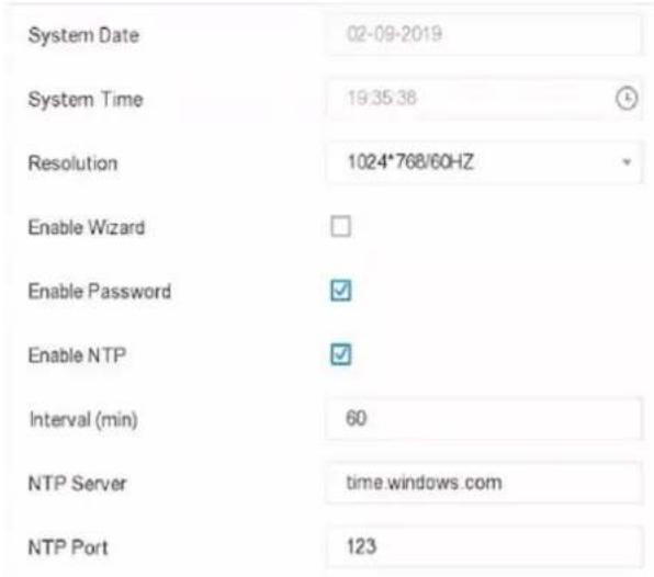
Figure 5-1 General Settings
- Configure the parameters as your desire.
Enable Wizard
The wizard will pop up after the device starts up.
Enable Password
You need to enter password for authentication if the device automatically logged out.
Enable NTP
Network time protocol (NTP) is a networking protocol for time synchronization. The device can connect to NTP (network time protocol) server to sync time.
Interval (min)
Time interval between two time synchronization with NTP server.
NTP Server
IP address of the NTP server.
NTP Port
Port of the NTP server.
- Click Apply.
5.1.2 User
Add User
There is a default account: Administrator. The administrator user name is admin. Administrator has the permission to add, delete, and edit user. Guest user only has live view, playback, and log search permission.
Steps
- Go to Configuration → User.
- Click Add and confirm your admin password.
![Add User User Name test Password ********** Note: Valid password range [8-16]. You can use a combination of numbers, lowercase, uppercase and special character for your password with at least two kinds of them contained Strong Confirm ********** User Level Guest Normal user only has live view, playback, and log search permission. OK Cancel](/content/2026/06/1405857/images/e5aed11688e4576d8a38a9014be8ad3f9cf4bb452285d5954c4e9e552a8eec91.jpg)
Figure 5-2 Add User
- Enter user name.
- Enter the same password in Password and Confirm.
Warning
We highly recommend you create a strong password of your own choosing (Using a minimum of 8 characters, including at least three of the following categories: upper case letters, lower case letters, numbers, and special characters.) in order to increase the security of your product. And we recommend you reset your password regularly, especially in the high security system, resetting the password monthly or weekly can better protect your product.
5. Click OK.
- Click to edit user.
Set Password Resetting Email
When you forgot your login pattern and password, the device will send an email contains verification code to your email for password resetting.
Steps
- Go to Configuration → User.
- Click Password Resetting Email.
- Enter admin password for authorization.
- Enter an email address.
- Click OK.
Reset Password
You can reset your password when you forgot your login pattern and password.
Steps
- Click Forgot Password at the password login interface.
- Follow the wizard to reset password.
5.1.3 Exception
You can receive exception events hint in alarm center, and set exception linkage actions.
Steps
- Go to Configuration → System → Exception.
- Optional: Configure event hint. When the set events occur, you will receive hints in alarm center.
1) Check Event Hint.
2) Click at the upper-right corner of local menu to enter alarm center.
3) Select an event type.
4) Click Set to select events to hint.
3. Set Exception Type
- Select Normal Linkage and Trigger Alarm Output type for exception linkage actions.

Figure 5-3 Exceptions
- Click Apply.
5.2 Network Configuration
5.2.1 General
You shall properly configure the network settings before operating the device over network.
Steps
- Go to Configuration → Network → General.

Figure 5-4 Network
- Set network parameters.
DHCP
If the DHCP server is available, you can check Enable DHCP to automatically obtain an IP address and other network settings from that server.
Obtain DNS Automatically
If DHCP is checked. You can check Obtain DNS Automatically to automatically obtain Preferred DNS Server and Alternate DNS Server.
- Click Apply.
5.2.2 Guarding Vision
Guarding Vision provides mobile phone application and platform service to access and manage your connected devices, which enables you to get a convenient remote access to the surveillance system.
Steps
- Go to Configuration → Network → Platform Access.
- Select Access Type as Guarding Vision.
- Check Enable. The service terms will pop up.
1) Scan the QR code to read the service terms and privacy statement.
2) Check I have read and agree to Service Terms and Privacy Statement. if you agree the service terms and privacy statement.
3) Click OK.
- Optional: Check Stream Encryption. It requires to enter verification code in remote access and live view after this function is enabled.
- Optional: Check Custom, and edit Server Address.
- Enter a code in Verification Code. You can click Refresh to randomly generate a verification code.
- Click Apply.
What to do next
You can access your video recorder via Guarding Vision.
- Scan the first QR code to download Guarding Vision app.
- Open Guarding Vision and scan the second QR code to add your video recorder. Refer to Guarding Vision Mobile Client User Manual for details of adding the video recorder to Guarding Vision and more operation instructions.
5.2.3 Email
Set an email account to receive event notification.
Before You Start
- Ensure your video recorder is in a local area network with an SMTP mail server.
- Configure your network parameters. Refer to General for details.
Steps
- Go to Configuration → Network → Email.

Figure 5-5 Email
2. Set email parameters
Server Authentication
(Optional), check it to enable the server authentication feature.
User Name
The user account of email sender for SMTP server authentication.
Password
The password of email sender for SMTP server authentication.
SSL/TLS
(Optional), check it to enable SSL/TLS if it required by the SMTP server.
Sender
The sender name.
Sender's Address
The sender's email address.
Select Receiver
Select a receiver. Up to 3 receivers are available.
Receiver
The receiver name.
Receiver's Address
The receiver's email address.
iNote
- For network cameras, the event images are directly sent as the email attachment. One network camera only sends one picture.
- For analog cameras, 3 attached pictures will be sent for one analog camera when an event occurs.
3. Click Apply.
5.3 Camera Management
5.3.1 Configure Signal Input
For certain models of Digital Video Recorder (DVR), you can configure the analog and IP signal input types.
Steps
- Go to Configuration → Camera → Analog.
- Select signal input type as HD/CVBS or IP for each channel.
HD/CVBS
Four types of analog signal inputs including Turbo HD, AHD, HDCVI, and CVBS can be connected randomly for the channel.
IP
Network camera can be connected for the channel.

Figure 5-6 Signal Input Type
- Click Apply. You can view the maximum network camera accessible number in Max. IP Camera Number.
5.3.2 Network Camera
Activate Network Camera
Only activated network cameras can be added.
Before You Start
Ensure your network camera is on the same network segment with your video recorder.
Steps
- Go to Configuration → Camera → IP Camera. Security column indicates whether the network camera is activated.
- Click Inactive of a desired camera.
![Activation Use Channel Default Password Password Create New Password Confirm Confirm New Password Note:Valid password range [8-16]. You can use a c... Password Strength OK Cancel](/content/2026/06/1405857/images/5efea289a4bdc831c517d7722e7324540497e5f1a657b152f45b0830ce4fc97e.jpg)
Figure 5-7 Activation
- Set the camera password.
Use the same password as video recorder Check Use Channel Default Password to activate the camera using the set channel default password.
Customize password Enter the same password in Password and Confirm.
Warning
We highly recommend you create a strong password of your own choosing (Using a minimum of 8 characters, including at least three of the following categories: upper case letters, lower case letters, numbers, and special characters.) in order to increase the security of your product. And we recommend you reset your password regularly, especially in the high security system, resetting the password monthly or weekly can better protect your product.
- Click OK.
Add Network Camera by Device Password
Add network cameras which the password is the same as your video recorder.
Before You Start
- Ensure your network camera is on the same network segment with your video recorder.
- Ensure the network connection is valid and correct. Refer to General for details.
- Ensure the network camera password is the same as your video recorder.
Steps
- Go to Configuration → Camera → IP Camera. The online cameras on the same network segment with your video recorder are displayed in the camera list.
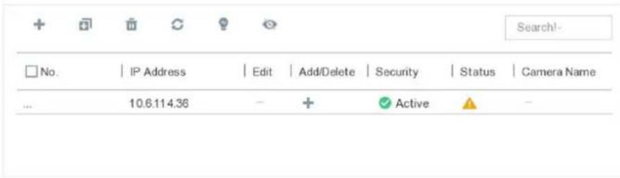
Figure 5-8 IP Camera Management Interface
- Click to add the camera.
Add Network Camera Manually
Before You Start
- Ensure your network camera is on the same network segment with your video recorder.
- Ensure the network connection is valid and correct.
- Ensure the network camera is activated.
Steps
- Go to Configuration → Camera → IP Camera.
- Click .+
- Set network camera parameters, including IP address, protocol, management port, etc. You can check Use IPC Active Password to use the device password to add network camera(s).
- Optional: Click Add More to add another network camera.
- Click OK.

Figure 5-9 Add Network Camera
Edit Connected Network Camera
You can edit the IP address, protocol and other parameters of the added network cameras.
Steps
- Go to Configuration → Camera → IP Camera.
- Click to edit the selected camera.
Channel Port
If the connected device is an encoding device with multiple channels, you can select the channel port No. to choose a connecting channel.
- Click OK.
5.3.3 OSD Settings
Configure OSD (On-Screen Display) settings for the camera, including date format, camera name, etc.
Steps
- Go to Configuration → Camera → OSD.
- Select a camera.
![Camera [A1] Camera 01 Camera Name Camera 01 ✓ Display Name ✓ Display Date ✓ Display Week Date Format MM-DD-YYYY Time Format 24-hour Display Mode Non-Transparent & Not](/content/2026/06/1405857/images/35047c33ffc6fad77700f494d7932872dc39ae0e5804ea49a58fd0397ea4086b.jpg)
Figure 5-10 OSD
- Drag the text frames on the preview window to adjust the OSD position.
- Click Apply.
5.3.4 Smart Event
Motion Detection
Motion detection enables the video recorder to detect the moving objects in the monitored area and trigger alarms.
Steps
- Go to Configuration → Camera → Smart Event → Motion Detection.
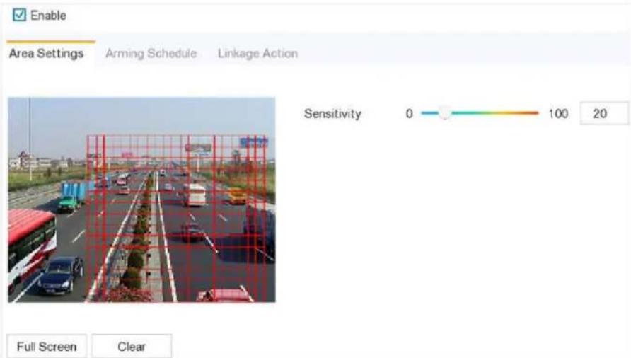
Figure 5-11 Motion Detection
- Select a camera.
-
Check Enable.
-
Set the motion detection area.
| Full screen | Click Full Screen to set the motion detection area as full screen. |
| Customized area | Drag on the preview window to draw motion detection areas. |
| Clear | Click Clear to clear the current motion detection areas. |
- Adjust Sensitivity. Sensitivity allows you to calibrate how readily movement triggers the alarm. A higher value results in the more readily to triggers motion detection.
- Set the arming schedule. Refer to for Configure Arming Schedule details.
- Set the linkage actions. Refer to Configure Alarm Linkage Action for details.
- Click Apply.
Intrusion Detection
Intrusion detection detects people, vehicles, or objects that enter and loiter in a pre-defined virtual region.
Steps
- Go to Configuration → Camera → Smart Event → Intrusion.
- Select a camera.
- Check Enable Intrusion Detection.
- Set detection rules and detection areas.
1) Set Arming Area. Up to 4 arming areas are selectable.
2) Set Sensitivity. The size of the object that can trigger the alarm. The higher the value is, the easier the detection alarm can be triggered. Its range is [1-100].
3) Click Draw Area to draw a quadrilateral detection region.
- Set the arming schedule. Refer to for Configure Arming Schedule details.
- Set the linkage actions. Refer to Configure Alarm Linkage Action for details.
- Click Apply.
Line Crossing Detection
Line crossing detection detects people, vehicles, and objects crossing a set virtual line. The detection direction can be set as bidirectional, from left to right or from right to left.
Steps
- Go to Configuration → Camera → Smart Event → Line Crossing.
- Select a camera.
- Set line crossing detection rules and detection areas.
1) Set Arming Area. Up to 4 arming areas are selectable.
2) Select Direction as A<->B, A->B, or A<-B.
A<->B
Only the arrow on the B side shows. An object crossing a configured line in both directions can be detected and trigger alarms.
A->B
Only an object crossing the configured line from the A side to the B side can be detected.
B->A
Only an object crossing the configured line from the B side to the A side can be detected.
3) Set Sensitivity. The higher the value is, the easier the detection alarm will be triggered.
4) Click Draw Area, and set two points in the preview window to draw a virtual line.
- Set the arming schedule. Refer to for Configure Arming Schedule details.
- Set the linkage actions. Refer to Configure Alarm Linkage Action for details.
- Click Apply.
Configure Arming Schedule
Steps
- Select Arming Schedule.
- Choose one day of a week and set the time segment. Up to eight time periods can be set within each day.

Time periods shall not be repeated or overlapped.
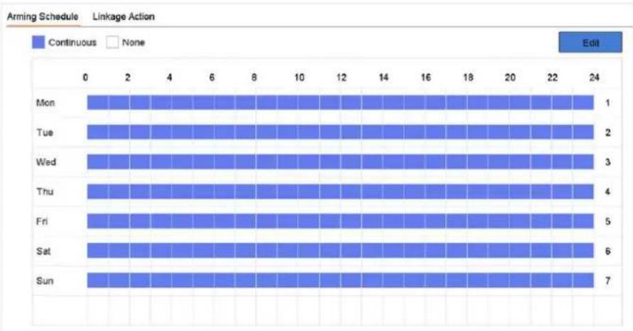
bar
| Day | Continuous | None | |-------|------------|------| | Mon | 1 | | | Tue | 2 | | | Wed | 3 | | | Thu | 4 | | | Fri | 5 | | | Sat | 6 | | | Sun | 7 | |Figure 5-12 Set Arming Schedule
- Click Apply.
Configure Alarm Linkage Action
Alarm linkage actions will be activated when an alarm or exception occurs.
Steps
1. Click Linkage Action.
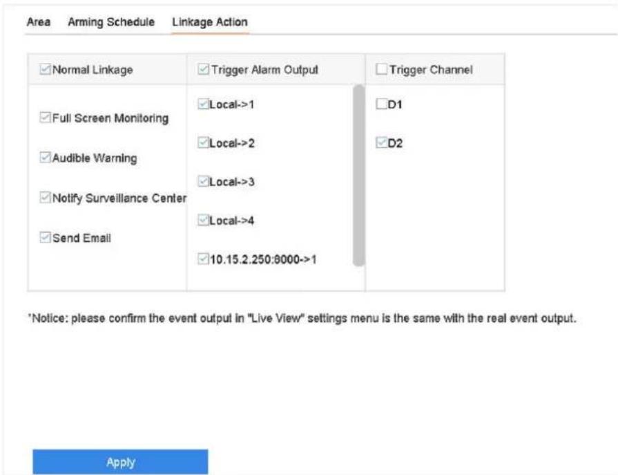
Figure 5-13 Linkage Actions
- Set normal linkage actions, trigger alarm output, trigger recording channel, etc.
Full Screen Monitoring
The local monitor will display the alarming channel image in full screen when an alarm is triggered. It requires to select the alarming channel(s) in Trigger Channel.
Audible Warning
It will trigger an audible beep when an alarm is triggered.
Notify Surveillance Center
The device will send an exception or alarm signal to the remote client software when an alarm is triggered.
Send Email
It will send an email with alarm information when an alarm is triggered.
PTZ Linkage
It will trigger PTZ actions (e.g., call preset/patrol/pattern) when smart events occur.
3. Click Apply.
5.4 Recording Management
5.4.1 Storage Device
Initialize HDD
A newly installed hard disk drive (HDD) must be initialized before it can be used to save videos and information.
Before You Start
Install at least an HDD to your video recorder. For detailed steps, refer to Quick Start Guide.
Steps
- Go to Configuration → Record → Storage.
- Select an HDD.
- Click Init.
Repair Database
Repair an HDD that with error in database. Please operate it with the help of professional technical support.
Add Network Disk
You can add the allocated NAS or IP SAN disk to the video recorder, and use it as a network HDD. Up to 8 network disks can be added.
Steps
- Go to Configuration → Record → Storage.
- Click Add.
- Select NetHDD.
- Set Type as NAS or IPSAN.
- Enter NetHDD IP address.
- Click Search to search the available disks.

Figure 5-14 Add NetHDD
- Select NAS disk from the list, or manually enter the directory in NetHDD Directory.
- Click OK. The added NetHDD will be displayed in the storage device list.
5.4.2 Configure Recording Schedule
Video recorder will automatically start/stop recording according to the configured schedule.
Configure Continuous Recording
Steps
- Go to Configuration → Record → Parameter.
- Set the continuous main stream/sub-stream recording parameters for the camera. Refer to Configure Recording Parameter for details.
- Go to Configuration → Record → Schedule.
- Select recording type as Continuous. Refer to Edit Schedule for details.
Configure Event Recording
You can configure the recording triggered by the motion detection, line crossing detection, and intrusion detection.
Steps
- Go to Configuration → Event → Smart Event.
-
Configure the event detection and select the channels to trigger the recording when an event occurs. Refer to Smart Event for details.
-
Go to Configuration → Record → Parameter.
- Set the continuous main stream/sub-stream recording parameters for the camera. Refer to Configure Recording Parameter for details.
- Go to Configuration → Record → Schedule.
- Select recording type as Event. Refer to Edit Schedule for details.
Edit Schedule
Steps
- Go to Configuration → Record → Schedule.
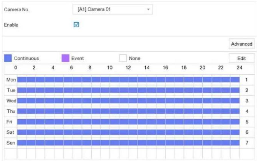
bar
| Day | Continuous | Event | None | Edit | |---|---|---|---|---| | Mon | 1 | 0 | 0 | 0 | | Tue | 2 | 0 | 0 | 0 | | Wed | 3 | 0 | 0 | 0 | | Thu | 4 | 0 | 0 | 0 | | Fri | 5 | 0 | 0 | 0 | | Sat | 6 | 0 | 0 | 0 | | Sun | 7 | 0 | 0 | 0 |Figure 5-15 Recording Schedule
Continuous
Continuous recording.
Event
Recording triggered by all event triggered alarm.
- Select a camera in CameraNo.
- Check Enable.
- Configure the recording schedule.
Edit Schedule
- Click Edit.
- Select a day to configure in Weekday.
- To set an all-day recording schedule, check All Day and select schedule type.
- To set other schedules, uncheck All Day, and set Start/End Time and schedule type.
iNote
Up to 8 periods can be configured for each day. And the time periods cannot be overlapped with each other.
- Click OK to save the settings and go back to upper level menu.

5 Edit Schedule
- Click to select schedule type as Continuous or Event.
-
On the table, drag the mouse on the desired period to draw a colored bar.
-
Click Apply.
5.4.3 Configure Recording Parameter
Steps
- Go to Configuration → Record → Parameter.
- Configure recording parameters.
Main Stream
Main stream refers to the primary stream that affects data recorded to the hard disk drive and will directly determine your video quality and image size. Comparing with the sub-stream, the main stream provides a higher quality video with higher resolution and frame rate.
Sub-Stream
Sub-stream is a second codec that runs alongside the mainstream. It allows you to reduce the outgoing internet bandwidth without sacrificing your direct recording quality. Sub-stream is often exclusively used by smartphone applications to view live video. Users with limited internet speeds may benefit most from this setting.
Frame Rate
Frame rate refers to how many frames are captured each second. A higher frame rate is advantageous when there is movement in the video stream, as it maintains image quality throughout.
Resolution
Image resolution is a measure of how much detail a digital image can hold: the greater the resolution, the greater the level of detail. Resolution can be specified as the number of pixel-columns (width) by the number of pixel-rows (height), e.g., 1024 × 768 .
Bitrate
The bit rate (in kbit/s or Mbit/s) is often referred to as speed, but actually defines the number of bits/time unit and not distance/time unit.
iNote
Higher resolution, frame rate, and bitrate provide you better video quality, but it also requires more internet bandwidth and uses more storage space on the hard disk drive.
3. Click Apply.
Chapter 6 Configuration (Expert Mode)
Go to Configuration, and click Expert Mode at the lower-left corner.
6.1 System Configuration
6.1.1 General
You can configure the output resolution, system time, mouse pointer speed, etc.
Steps
- Go to Configuration → System → General.

Figure 6-1 General Settings
- Configure the parameters as your desire.
Language
The default language is English.
Device Name
Edit the video recorder name.
Device No.
The number is required in the connection with remote control, network keyboard, etc. Edit the serial number of video recorder. The Device No. can be set in the range of 1\~255, and the default No. is 255.
Auto Log Out
Set timeout time for menu inactivity.
Enable Wizard
The wizard pops up after the device starts up.
Enable Password
You need to enter password for authentication if the device automatically logged out.
Menu Output Mode
Choose output to display local menu.
VGA/HDMI Resolution
Select the output resolution, which must be the same with the resolution of the VGA/HDMI display.
Output Standard
Select the CVBS output standard as PAL or NTSC.
Mouse Pointer Speed
Set the speed of mouse pointer; 4 levels are configurable.
3. Click Apply.
6.1.2 Live View
Configure General Parameters
You can configure the output interface, mute or turning on the audio, event output interface, etc.
Steps
- Go to Configuration → System → Live View → General.

Figure 6-2 Live View-General
- Configure the Live View parameters.
Live View Mode
Select the live view window division.
Dwell Time
The time to dwell in a camera before switching to next camera when auto-switch in live view is enabled.
Event Output
Select the output to show event video.
Full Screen Monitoring Dwell Time
Set the time to show alarm event image.
Enable Audio Output
Turn on/off audio output for the selected video output.
Volume
Adjust the live view, playback, and two-way audio volume for the selected video output interface.
3. Click Apply.
Configure Live View Layout
Steps
- Go to Configuration → System → Live View → View.
- Select Video Output Interface to configure.
- Click to select a window and click a camera No. in the camera list you would like to display. + means no camera is displayed on the window.
- You can
Table 6-1
| Icon | Description |
| Start live view of all the cameras in order. | |
| Stop live view of all the cameras. |
5. Click Apply.
Configure Channel-Zero Encoding
Enable the channel-zero encoding when you need to get a remote view of many channels in real time from a web browser or CMS (Client Management System) software, in order to decrease the
bandwidth requirement without affecting the image quality.
Steps
- Go to Configuration → System → Live View → General.
- Set Video Output Interface as Channel-Zero.
- Go to Configuration → System → Live View → Channel-Zero.

Figure 6-3 Channel-Zero
- Check Enable Channel-Zero Encoding.
- Configure Frame Rate, Max. Bitrate Mode, and Max. Bitrate. The higher frame rate and bitrate settings result in higher bandwidth requirement.
- Click Apply.
6.1.3 User
Refer to User for details.
6.2 Network Configuration
6.2.1 TCP/IP
TCP/IP must be properly configured before you operate video recorder over network.
Steps
- Go to Configuration → Network → General → TCP/IP.
- Configure network parameters.
Working mode
- Multi-address Mode:
- The parameters of the two NIC cards can be configured independently. You can select LAN1 or LAN2 in the NIC type field for parameter settings. You can select one NIC card as default route. And then the system is connecting with the extranet and the data will be forwarded through the default route.
-
Net-fault Tolerance Mode:
-
The two NIC cards use the same IP address, and you can select the Main NIC to LAN1 or LAN2. By this way, in case of one NIC card failure, the video recorder will automatically enable the other standby NIC card so as to ensure the normal running of the whole system.
- Load Balance Mode:
- By using the same IP address and two NIC cards share the load of the total bandwidth, which enables the system to provide two Gigabit network capacity.

Working mode is only available for certain models.
NIC Type
Select NIC type as your desire.
DHCP
If the DHCP server is available, you can check Enable DHCP to automatically obtain an IP address and other network settings from that server.
MTU
The maximum transmission unit (MTU) is the size of the largest network layer protocol data unit that can be communicated in a single network transaction.
Obtain DNS Automatically
If DHCP is checked. You can check Obtain DNS Automatically to obtain Preferred DNS Server and Alternate DNS Server.
3. Click Apply.
6.2.2 DDNS
Dynamic domain name server (DDNS) maps dynamic user IP addresses to a fixed domain name server.
Before You Start
Register DynDNS, PeanutHull and NO-IP services with your ISP.
Steps
- Go to Configuration → Network → General → DDNS.

Figure 6-4 DDNS
- Check Enable.
- Select a DDNS type.
- Enter parameters including service address, domain name, etc.
- Click Apply.
What to do next
You can view DDNS status in Status.
6.2.3 NAT
Two ways are provided for port mapping to realize the remote access via the cross-segment network, UPnP™ and manual mapping.
Before You Start
Enable the UPnP™ function of your router if UPnP™ is required. When the device network working mode is multi-address, the default device route should be on the same network segment as the LAN IP address of the router.
Steps
- Configuration → Network → General → NAT.
- Check Enable.
- Select Mapping Type as Manual or Auto
Auto The port mapping items are read-only, and the external ports are set by the router automatically. You can click Refresh to get the latest status of the port mapping.
Manual Select an external port type. Click to edit External Port. You can use the default external port No., or change it according to actual requirements. External Port indicates the port No. for port mapping in the router.
The value of the RTSP port No. should be 554 or between 1024 and 65535, while the value of the other ports should be between 1 and 65535 and the value must be different from each other. If multiple
devices are configured for the UPnP™ settings under the same router, the value of the port No. for each device should be unique.
- Set the virtual server of your router, including internal source port, external source port, etc. The virtual server parameters shall be corresponding with your device port.
6.2.4 Ports (More Settings)
Set different port types to enable relevant functions as your desire. Go to Configuration → Network → General → More Settings.
Alarm Host IP/Port
The device will send the alarm event or exception message to the alarm host when an alarm is triggered. The remote alarm host must have the client management system (CMS) software installed.
Alarm Host IP refers to the IP address of the remote PC on which the CMS software (e.g., iVMS-4200) is installed, and the Alarm Host Port (7200 by default) must be the same as the alarm monitoring port configured in the software.
Server Port
For remote client software access. Ranges from 2000 to 65535. The default value is 8000.
HTTP Port
For remote web browser access. The default value is 80.
Multicast IP
Multicast can be configured to enable live view for cameras that exceed the maximum number allowed through network. A multicast IP address covers Class-D IP ranging from 224.0.0.0 to 239.255.255.255 and it is recommended to use the IP address ranging from 239.252.0.0 to 239.255.255.255.
When adding a device to the CMS software, the multicast address must be the same as that of the device.
RTSP Port
RTSP (Real Time Streaming Protocol) is a network control protocol designed for use in entertainment and communications systems to control streaming media servers. The port is 554 by default.
Output Bandwidth Limit
You can check the checkbox to enable output bandwidth limit.
Output Bandwidth
After enable the output bandwidth limit, input the output bandwidth.
iNote
- The output bandwidth limit is used for the remote live view and playback.
- The default output bandwidth is the maximum limit.

Figure 6-5 Port Settings
6.2.5 Guarding Vision
Go to Configuration → Network → Platform Access. Refer to Guarding Vision for details.
6.2.6 Advanced Settings
Steps
- Go to Configuration → Network → Advanced Settings.
- Configure the parameters as your desire.
RTSP
You can specifically secure the stream data of live view by setting the RTSP authentication.
RTSP Authentication Type
Two authentication types are selectable, if you select digest, only the request with digest authentication can access the video stream by the RTSP protocol via the IP address. For security reasons, it is recommended to select digest as the authentication type.
ISAPA
ISAPI (Internet Server Application Programming Interface) is an open protocol based on HTTP, which can realize the communication between the system devices (e.g., network camera, NVR, etc.). The video recorder is as a server, the system can find and connect the video recorder.
HTTP
The admin user account can disable the HTTP service from the GUI or the web browser. After the HTTP is disabled, all the related services, including the ISAPI, Onvif and Gennetc, will terminate as well.
HTTP Authentication
If you need to enable the HTTP service, you can set the HTTP authentication to enhance the access security. Two authentication types are selectable, for security reasons, it is recommended to select digest as the authentication type.
IP Camera Occupation Detection
The function detects the network camera status. If the network camera has been added by another video recorder, the network camera status will show as in Online Device list.
- Click Apply.
6.3 Camera Management
6.3.1 Configure Signal Input
For certain models of Digital Video Recorder (DVR), you can configure the analog and IP signal input types.
Steps
- Go to Configuration → Camera → Analog.
- Select signal input type as HD/CVBS or IP.
HD/CVBS
Four types of analog signal inputs including Turbo HD, AHD, HDCVI, and CVBS can be connected randomly for the channel.
IP
Network camera can be connected for the channel.
- Click Advanced Settings to set parameters as your desire.
Enhanced IPC Mode
If the option is checked, the maximum number of IP channel will increase. But it will make smart events unavailable in analog camera.
Enhanced VCA Mode
If the option is checked, it will maximize the number of line crossing detection and intrusion detection in analog channel.
4MP Lite Mode
If the option is checked, image of 4 MP or below resolution can be encoded in full frame rate.
1080P Lite Mode
If the option is checked, signal of 1080p resolution is available for the analog channels.
- Click Apply. You can view the maximum network camera accessible number in Max. IP Camera Number.
6.3.2 Network Camera
Activate Network Camera
Only activated network cameras can be added.
Before You Start
Ensure your network camera is on the same network segment with your video recorder.
Steps
- Go to Configuration → Camera → Camera → IP Camera.
- Click Online Device. The online cameras in the same network segment with your video recorder will be displayed in the camera list. The Security column shows whether the network camera is active.
| Online Device | |||||||
| Refresh | + Add | Activate | |||||
| No. | Status | Security | IP Address | Edit | Protocol | Management ... | |
| 1 | - | Inactive | 192.168.1.64 | / | HIKVISION | 8000 | |
Figure 6-6 Online Device
- Check an inactive network camera and click Activate.
![Activation Use Channel Default Password Password Create New Password Confirm Confirm New Password Note:Valid password range [8-16]. You can use a c... Password Strength OK Cancel](/content/2026/06/1405857/images/138921d13696987a718cc424ae1eb6ad9e76bfcfb0eae586341e27b4b073f4dc.jpg)
Figure 6-7 Activation
-
Choose one of the following methods to set camera password.
-
Use video recorder password: Check Use Channel Default Password to activate the camera using the set channel default password.
- Customize password: Enter the same password in Password and Confirm.
Warning
Strong Password recommended-We highly recommend you create a strong password of your own choosing (Using a minimum of 8 characters, including at least three of the following categories: upper case letters, lower case letters, numbers, and special characters.) in order to increase the security of your product. And we recommend you reset your password regularly, especially in the high security system, resetting the password monthly or weekly can better protect your product.
5. Click OK.
Add Automatically Searched Online Network Camera
Add the network cameras to your video recorder.
Before You Start
- Ensure your network camera is on the same network segment with your video recorder.
- Ensure the network connection is valid and correct.
- Ensure the network camera password is the same as your video recorder.
Steps
-
Go to Configuration → Camera → Camera → IP Camera.
-
Click Online Device. The online cameras on the same network segment will be displayed in the list.
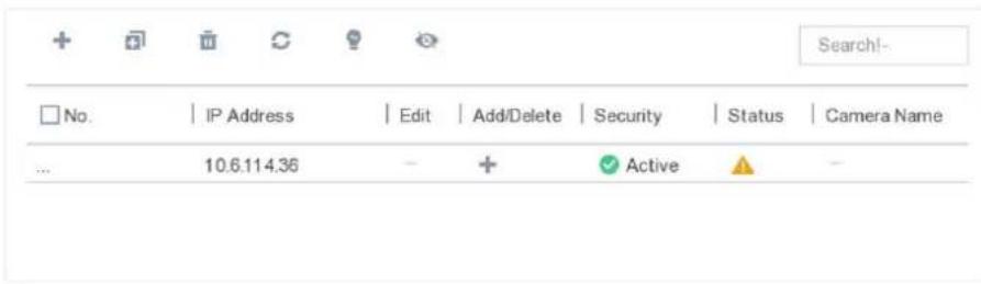
Figure 6-8 Online Device
- Select a network camera, and click Add to add it.
Add Network Camera Manually
Add the network cameras to your video recorder.
Before You Start
- Ensure your network camera should be in the same network segment with your video recorder.
- Ensure the network connection is valid and correct.
- Activate the network camera to add.
Steps
- Go to Configuration → Camera → IP Camera.
- Click .+

Figure 6-9 Add IP Camera
- Enter information of the network camera to add.
Use Channel Default Password
If it is checked, the video recorder will add the camera by the set channel default password. 4. Click Add.
Edit Connected Network Camera
You can edit the IP address, protocol and other parameters of the added network cameras.
Steps
- Go to Configuration → Camera → IP Camera.
- Click of an added network camera.
Channel Port
If the connected device is an encoding device with multiple channels, you can choose the channel to connect by selecting the channel port No. in the drop-down list.
- Click OK.
Example
Enter an example that illustrates the current task (optional).
What to do next
Enter the tasks the user should do after finishing this task (optional).
Import/Export IP Camera Configuration File
The information of added network camera can be generated into an excel file and exported to the local device for backup, including the IP address, manage port, password of admin, etc. And the exported file can be edited on your computer, like adding or deleting the content, and copy the setting to other devices by importing the excel file to it.
Before You Start
Connect a backup device like USB flash drive to your video recorder.
Steps
- Go to Configuration → Camera → IP Camera.
- Click
- Click Export to export configuration files to the connected backup device.
- To import a configuration file, select the file from the selected backup device and click Import.
After the importing process is completed, you must reboot the video recorder.
Advanced Settings
Steps
- Go to Configuration → Camera → IP Camera.
- Click ...
- Configure the parameters as your desire.
H.265 Auto Switch Configuration
If you enable the option, video recorder will automatically switch to H.265 stream for the network camera (which supports H.265 video format) for the initial access.
Upgrade
Upgrade the added network cameras.
Channel Default Password Management
Change the default password of activating and adding network camera.
6.3.3 Display Settings
Configure the OSD (On-Screen Display), image settings, exposure settings, day/night switch
settings, etc.
Steps
- Go to Configuration → Camera → Display.
- Select Camera.
- Configure parameters as your desire.
OSD Settings
Configure the OSD (On-screen Display) settings for the camera, including date/time, camera name, etc.
Image Settings
Customize the image parameters including the brightness, contrast, and saturation for the live view and recording effect.
Exposure
Set the camera exposure time (1/10000 to 1 sec). A larger exposure value results in a brighter image.
Day/Night Switch
The camera can be set to day, night, or auto switch mode according to the surrounding illumination conditions.
Backlight
Set the camera's wide dynamic range (0 to 100). When the surrounding illumination and the object have large differences in brightness, you should set the WDR value.
Image Enhancement
For optimized image contrast enhancement.
![Camera [D1] Camera 01 Camera Name Camera 01 OSD Settings > Image Settings > Exposure Day/Night Switch > Backlight > Image Enhancement > Camera Parameters Settings >](/content/2026/06/1405857/images/391113e7a94adc29fcaa37f9943cf28b54600939c283b8f4533dcd8a113e0aa1.jpg)
Figure 6-10 OSD
- Drag the text frames on the preview window to adjust the OSD position.
- Click Apply.
6.3.4 Privacy Mask
You are allowed to configure the privacy mask areas that cannot be viewed or recorded.
Steps
- Go to Configuration → Camera → Privacy Mask.
- Select Camera.
- Check Enable.
![Camera [A1] Camera 01 Enable Clear All Clear Area 1 Clear Area 2 Clear Area 3 Clear Area 4](/content/2026/06/1405857/images/b5bd05dd3638b8164f448c7af374fe9ddbd85c7c2dfcc27ad187173bc0c954c7.jpg)
Figure 6-11 Privacy Mask
- Drag to draw an area on the window. The frames of the areas will be marked with different colors.
iNote
Up to 4 privacy mask areas can be configured. The size of each area can be adjusted.
- Click Apply.
6.4 Event Configuration
6.4.1 Normal Event
Motion Detection
Motion detection enables the video recorder to detect the moving objects in the monitored area and trigger alarms.
Steps
- Go to Configuration → Event → Normal Event → Motion Detection.
![Camera [A1] Camera 01 Enable Area Settings Arming Schedule Linkage Action Sensitivity 0 100 20 False Alarm Filter Full Screen Clear](/content/2026/06/1405857/images/537dc70bf323eb6b4233d83fdd18f8e02f15c7da15bd967a7832541a7ea88895.jpg)
Figure 6-12 Motion Detection
- Select Camera to configure.
- Check Enable.
-
Set the motion detection area. Choose from:
-
Full screen: Click Full Screen to set the motion detection area as full screen.
- Customized area: Drag on the preview window to draw motion detection areas.
-
Clear: Click Clear to clear the current motion detection areas.
-
Adjust Sensitivity as your desire.
Sensitivity
It allows you to calibrate how readily movement triggers the alarm. A higher value results in the more readily to triggers motion detection.
- Check False Alarm Filter. Then only when both the motion detection and PIR events are triggered, the motion detection alarm will be triggered.
iNote
The option is only available for PIR camera.
- Set the arming schedule.
- Set the linkage actions.
- Click Apply.
Video Tampering
Trigger alarm when the lens is covered and take alarm response actions.
Steps
- Go to Configuration → Event → Normal Event → Video Tampering Detection.
![Camera [A1] Camera 01 Enable Area Arming Schedule Linkage Action Sensitivity 0 2 0 Clear](/content/2026/06/1405857/images/72020688eb2e6f034f318ea9509515a6c6a50e239a8e4e24e2e63a5cc3b6259f.jpg)
Figure 6-13 Video Tampering
- Select Camera.
- Check Enable.
- Adjust Sensitivity as your desire.
Sensitivity
The higher the value is, the more easily the video tampering can be triggered.
- Set the arming schedule.
- Set the linkage actions.
- Click Apply.
Video Loss
Detect video loss of a camera and take alarm response actions.
Steps
- Go to Configuration → Event → Normal Event → Video Loss.
- Select Camera.
- Check Enable.
- Set the arming schedule.
- Set the linkage actions.
- Click Apply.
Alarm Input
Set linkage actions for an external sensor alarm.
Steps
- Go to Configuration → Event → Normal Event → Alarm Input.
| Alarm Input No. | | Alarm Name | | Alarm Type | | Enable | | Edit |
| SOFT<-1 | No | / | ||
| SOFT<-2 | - | No | / | |
| SOFT<-3 | - | No | / | |
| SOFT<-4 | - | No | / | |
| SOFT<-5 | - | No | / | |
| SOFT<-6 | - | No | / | |
| SOFT<-7 | - | No | / | |
| SOFT<-8 | - | No | / | |
| SOFT<-9 | - | No | / | |
| SOFT<-10 | - | No | / | |
| SOFT<-11 | - | No | / | |
| SOFT<-12 | - | No | / | |
| SOFT<-13 | - | No | / | |
| SOFT<-14 | - | No | / | |
| SOFT<-15 | - | No | / |
Figure 6-14 Alarm Input
- Soft alarm input: Soft alarm input is triggered by SDK command.
-
Local alarm input: Local alarm input is triggered by the external device that connected to the video recorder's terminal block.
-
Click of a desired alarm input.

Figure 6-15 Edit Alarm Input
- Customize Alarm Name.
- Select alarm Type as N.O (normally open) or N.C (normally closed).
- Select Settings as Input to enable the function.
- Set the arming schedule.
- Set the linkage actions.
- Click Apply.
Alarm Output
Trigger an alarm output when an alarm is triggered.
Steps
- Go to Configuration → Event → Normal Event → Alarm Output.
- Click of a desired alarm output.
- Customize Alarm Name.
- Select Dwell Time.

Figure 6-16 Alarm Output
- Select Settings as Input to enable the function.
- Set the arming schedule.
- Click Apply.
Exception
Exception events can be configured to take the event hint in the live view window and trigger alarm outputs and linkage actions.
Steps
- Go to Configuration → Event → Normal Event → Exception.
- Configure event hint. When the set events occur, you will receive hints in alarm center.
1) Check Event Hint.
2) Select events to hint.Choose from:
- Click ⚙ of Event Hint Configuration to select events.
-
Click 📋 in the upper-right corner of local menu to enter alarm center to select events.
-
Select Exception Type to set its linkage actions.

Figure 6-17 Exceptions
- Set the arming schedule.
- Click Apply.
6.4.2 Smart Event
Face Detection
Face detection function detects the face appears in the surveillance scene, and some certain actions can be taken when the alarm is triggered.
Steps
- Go to Configuration → Event → Smart Event → Face Detection.
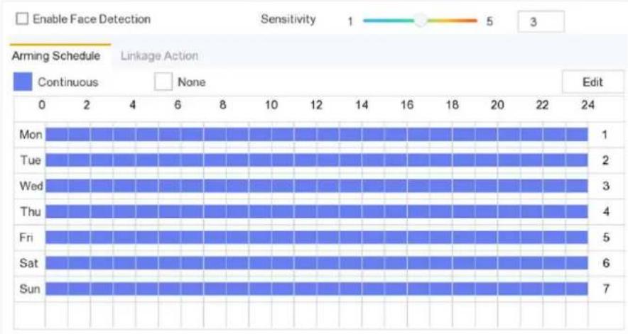
bar
| Day | Continuous | None | |---|---|---| | Mon | 1 | 0 | | Tue | 2 | 0 | | Wed | 3 | 0 | | Thu | 4 | 0 | | Fri | 5 | 0 | | Sat | 6 | 0 | | Sun | 7 | 0 |Figure 6-18 Face Detection
- Select Camera to configure.
- Check Save VCA Picture to save the captured pictures of VCA detection.
- Check Enable Face Detection.
- Adjust Sensitivity. Sensitivity: Range [1-100]. The higher the value is, the more easily the defocus image can trigger the alarm.
- Set the arming schedule.
- Set the linkage actions.
- Click Apply.
Intrusion Detection
Intrusion detection function detects people, vehicles, or objects that enter and loiter in a predefined virtual region.
Steps
- Go to Configuration → Event → Smart Event → Intrusion.
- Select Camera to configure.
- Check Enable Intrusion Detection.
- Check Save VCA Picture to save the captured pictures of VCA detection.
- Set the detection rules and detection areas.
1) Select Virtual Plane. Up to 4 arming areas are selectable.
2) Adjust Threshold and Sensitivity.
- Sensitivity: The size of the object that can trigger the alarm. The higher the value is, the more easily the detection alarm will be triggered. Its range is [1-100].
- Threshold: Range [1s-10s], the threshold for the time of the object loitering in the region. When the duration of the object in the defined detection area is longer than the set time, the alarm will be triggered.
3) Click Draw Area and draw a quadrilateral in the preview window by specifying four vertexes of the detection region.
-
Set the arming schedule.
-
Set the linkage actions.
- Click Apply.
Line Crossing Detection
Line crossing detection detects people, vehicles, and objects crossing a set virtual line. The detection direction can be set as bidirectional, from left to right or from right to left.
Steps
- Go to Configuration → Event → Smart Event → Line Crossing.
- Select Camera to configure.
- Check Enable Line Crossing Detection.
- Check Save VCA Picture to save the captured pictures of VCA detection.
- Set the detection rules and detection areas.
1) Select Arming Area. Up to 4 arming areas are selectable.
2) Select Direction as A<->B, A->B, or A<-B.
- A<->B: Only the arrow on the B side shows. An object crossing a configured line in both directions can be detected and trigger alarms.
- A->B: Only an object crossing the configured line from the A side to the B side can be detected.
- B->A Only an object crossing the configured line from the B side to the A side can be detected.
3) Click Draw Area and draw a quadrilateral in the preview window by specifying four vertexes of the detection region.
- Set the arming schedule.
- Set the linkage actions.
- Click Apply.
Region Entrance Detection
Region entrance detection function detects people, vehicle or other objects which enter a predefined virtual region from the outside place, and some certain actions can be taken when the alarm is triggered.
Steps
- Go to Configuration → Event → Smart Event → Region Entrance.
- Select Camera to configure.
- Check Enable Region Entrance Detection.
- Check Save VCA Picture to save the captured pictures of VCA detection.
- Set the detection rules and detection areas.
1) Select Arming Area. Up to 4 arming areas are selectable.
2) Click Draw Area and draw a quadrilateral in the preview window by specifying four vertexes of the detection region.
3) Adjust Sensitivity. Sensitivity: Range [0-100]. The higher the value is, the more easily the detection alarm can be triggered.
- Set the arming schedule.
- Set the linkage actions.
- Click Apply.
Region Exiting Detection
Region exiting detection function detects people, vehicle or other objects which exit from a predefined virtual region, and some certain actions can be taken when the alarm is triggered.
Steps
- Go to Configuration → Event → Smart Event → Region Exiting.
- Select Camera to configure.
- Check Enable Region Exiting Detection.
- Check Save VCA Picture to save the captured pictures of VCA detection.
- Set the detection rules and detection areas.
1) Select Arming Area. Up to 4 arming areas are selectable.
2) Click Draw Area and draw a quadrilateral in the preview window by specifying four vertexes of the detection region.
3) Adjust Sensitivity. Sensitivity: Range [0-100]. The higher the value is, the more easily the detection alarm can be triggered.
-
Set the arming schedule.
-
Set the linkage actions.
-
Click Apply.
Loitering Detection
Loitering detection function detects people, vehicle or other objects which loiter in a pre-defined virtual region for some certain time, and a series of actions can be taken when the alarm is triggered.
Steps
- Go to Configuration → Event → Smart Event → Loitering.
- Select Camera to configure.
- Check Enable Loitering Detection.
- Check Save VCA Picture to save the captured pictures of VCA detection.
- Set the detection rules and detection areas.
1) Select Arming Area. Up to 4 arming areas are selectable.
2) Click Draw Area and draw a quadrilateral in the preview window by specifying four vertexes of the detection region.
3) Adjust Threshold and Sensitivity.
- Sensitivity: Range [0-100]. The higher the value is, the more easily the detection alarm can be triggered.
-
Threshold: Range[1s-10s]. It defines the time of the object loitering in the region. If you set the value as 5, alarm is triggered after the object loitering in the region for 5s; and if you set the value as 0, alarm is triggered immediately after the object entering the region.
-
Set the arming schedule.
- Set the linkage actions.
- Click Apply.
People Gathering Detection
People gathering detection alarm is triggered when people gather around in a pre-defined virtual region, and a series of actions can be taken when the alarm is triggered.
Steps
- Go to Configuration → Event → Smart Event → People Gathering.
- Select Camera to configure.
- Check Enable People Gathering Detection.
- Check Save VCA Picture to save the captured pictures of VCA detection.
- Set the detection rules and detection areas.
1) Select Arming Area. Up to 4 arming areas are selectable.
2) Adjust Percentage. Percentage defines the gathering density of the people in the region. Usually, when the percentage is small, the alarm can be triggered when small number of people gathered in the defined detection region.
3) Click Draw Area and draw a quadrilateral in the preview window by specifying four vertexes of the detection region.
- Set the arming schedule.
- Set the linkage actions.
- Click Apply.
Fast Moving Detection
Fast moving detection alarm is triggered when people, vehicle or other objects move fast in a pre-defined virtual region, and a series of actions can be taken when the alarm is triggered.
Steps
- Go to Configuration → Event → Smart Event → Fast Moving.
- Select Camera to configure.
- Check Enable Fast Moving Detection.
- Check Save VCA Picture to save the captured pictures of VCA detection.
- Set the detection rules and detection areas.
1) Select Arming Area. Up to 4 arming areas are selectable.
2) Click Draw Area and draw a quadrilateral in the preview window by specifying four vertexes of the detection region.
3) Adjust Sensitivity. Sensitivity defines the moving speed of the object which can trigger the alarm. The higher the value is, the more easily a moving object can trigger the alarm.
- Set the arming schedule.
- Set the linkage actions.
- Click Apply.
Parking Detection
Parking detection function detects illegal parking in places such as highway, one-way street, etc., and a series of actions can be taken when the alarm is triggered.
Steps
- Go to Configuration → Event → Smart Event → Parking.
- Select Camera to configure.
- Check Enable Parking Detection.
- Check Save VCA Picture to save the captured pictures of VCA detection.
- Set the detection rules and detection areas.
1) Select Arming Area. Up to 4 arming areas are selectable.
2) Set Sensitivity and Time Threshold.
- Time Threshold defines the time of the vehicle parking in the region. If you set the value as 10, alarm is triggered after the vehicle stay in the region for 10s.
- Sensitivity: The size of the object that can trigger the alarm. The higher the value is, the more easily the detection alarm will be triggered. Its range is [1-100].
3) Click Draw Area and draw a quadrilateral in the preview window by specifying four vertexes of the detection region.
- Set the arming schedule.
- Set the linkage actions.
- Click Apply.
Unattended Baggage Detection
Unattended baggage detection function detects the objects left over in the pre-defined region such as the baggage, purse, dangerous materials, etc., and a series of actions can be taken when the alarm is triggered.
Steps
- Go to Configuration → Event → Smart Event → Unattended Baggage.
- Select Camera to configure.
- Check Enable Unattended Baggage Detection.
- Check Save VCA Picture to save the captured pictures of VCA detection.
- Set the detection rules and detection areas.
1) Select Arming Area. Up to 4 arming areas are selectable.
2) Set Sensitivity and Time Threshold.
- Time Threshold defines the time of the vehicle parking in the region. If you set the value as 10, alarm is triggered after the vehicle stay in the region for 10s.
- Sensitivity: The size of the object that can trigger the alarm. The higher the value is, the more easily the detection alarm will be triggered. Its range is [1-100].
3) Click Draw Area and draw a quadrilateral in the preview window by specifying four vertexes of the detection region.
- Set the arming schedule.
- Set the linkage actions.
8. Click Apply.
Object Removal Detection
Object removal detection function detects the objects removed from the pre-defined region, such as the exhibits on display, and a series of actions can be taken when the alarm is triggered.
Steps
- Go to Configuration → Event → Smart Event → Object Removal.
- Select Camera to configure.
- Check Enable Object Removal Detection.
- Check Save VCA Picture to save the captured pictures of VCA detection.
- Set the detection rules and detection areas.
1) Select Arming Area. Up to 4 arming areas are selectable.
2) Set Sensitivity and Time Threshold.
- Time Threshold range: [5s-3600s]. It defines the time of the objects removed from the region. If you set the value as 10, alarm is triggered after the object disappears from the region for 10s.
Sensitivity defines the similarity degree of the background image. Usually, when the sensitivity is high, a very small object taken from the region can trigger the alarm.
3) Click Draw Area and draw a quadrilateral in the preview window by specifying four vertexes of the detection region.
- Set the arming schedule.
- Set the linkage actions.
- Click Apply.
Audio Exception
Enter a short description of your task here (optional).
Before You Start
Enter the prerequisites here (optional).
Enter the context of your task here (optional).
Steps
- Enter your first step here.
Enter the result of your step here (optional).
Example
Enter an example that illustrates the current task (optional).
What to do next
Enter the tasks the user should do after finishing this task (optional).
Defocus
The image blur caused by defocus of the lens can be detected, and some certain actions can be taken when the alarm is triggered.
Steps
- Go to Configuration → Event → Smart Event → Defocus.

bar
| Day | Continuous | None | |---|---|---| | Mon | 1 | 0 | | Tue | 2 | 0 | | Wed | 3 | 0 | | Thu | 4 | 0 | | Fri | 5 | 0 | | Sat | 6 | 0 | | Sun | 7 | 0 |Figure 6-19 Defocus Detection
- Select Camera to configure.
- Check Save VCA Picture to save the captured pictures of VCA detection.
- Check Enable.
- Adjust Sensitivity. Sensitivity: Range [1-100]. The higher the value is, the more easily the defocus image can trigger the alarm.
- Set the arming schedule.
- Set the linkage actions.
- Click Apply.
Example
Enter an example that illustrates the current task (optional).
What to do next
Enter the tasks the user should do after finishing this task (optional).
Sudden Scene Change
Scene change function detects the change of surveillance environment affected by the external factors such as the intentional rotation of the camera and some certain actions can be taken when the alarm is triggered.
Steps
- Go to Configuration → Event → Smart Event → Audio Exception.
-
Select Camera to configure.
-
Check Save VCA Picture to save the captured pictures of VCA detection.
- Check Enable.
- Adjust Sensitivity. The Sensitivity in the Rule Settings ranges from 1 to 100, and the higher the value is, the more easily the change of scene can trigger the alarm.
iNote
For the analog cameras, the line crossing detection and intrusion detection conflict with sudden scene change detection. When sudden scene change detection is on, neither line crossing detection nor intrusion detection can be enabled.
- Set the arming schedule.
- Set the linkage actions.
- Click Apply.
6.4.3 Configure Arming Schedule
Steps
- Click Arming Schedule.
- Choose one day of a week and set the time segment. Up to eight time periods can be set within each day.
iNote
Time periods shall not be repeated or overlapped.
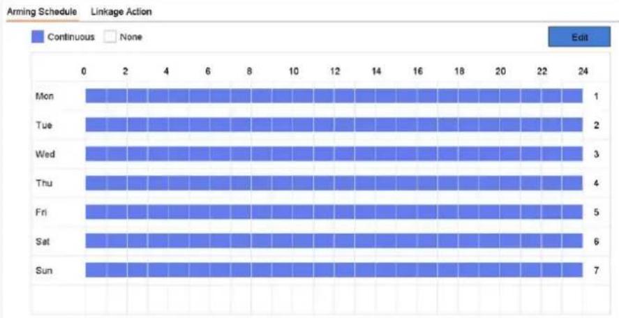
bar
| Day | Continuous | None | |-------|------------|------| | Mon | 1 | | | Tue | 2 | | | Wed | 3 | | | Thu | 4 | | | Fri | 5 | | | Sat | 6 | | | Sun | 7 | |Figure 6-20 Set Arming Schedule
- Click Apply.
6.4.4 Configure Alarm Linkage Action
Configure Full Screen Monitoring
When an alarm is triggered, the local monitor displays in full screen the video image from the alarming channel configured for full screen monitoring. And when the alarm is triggered simultaneously in several channels, you must configure the auto-switch dwell time.
Steps
- Go to Configuration → System → Live View → General.
- Set the event output and dwell time.
Event Output
Select the output to show event video.
Full Screen Monitoring Dwell Time
Set the time in seconds to show alarm event image. If alarms are triggered simultaneously in several channels, their full-screen images will be switched at an interval of 10 seconds (default dwell time).
- Go to Linkage Action interface of the alarm detection.
- Select Full Screen Monitoring alarm linkage action.
- Select the channel(s) in Trigger Channel settings you want to make full screen monitoring.

Auto-switch will terminate once the alarm stops and back to the live view interface.
Configure Audio Warning
The audio warning enables the video recorder to trigger an audible beep when an alarm is detected.
Steps
- Go to Configuration → System → Live View → General.
- Enable Audio Output and set Volume.
- Go to Linkage Action interface of the alarm detection.
- Select Audio Warning alarm linkage action.
Notify Surveillance Center
The video recorder can send an exception or alarm signal to the remote alarm host when an event occurs. The alarm host refers to the computer installed with client software (e.g., iVMS-4200,
iVMS-5200).
Steps
- Log into video recorder in web browser.
- Go to Configuration → Network → Advanced Settings → Other.
- Set Alarm Host IP and Alarm Host Port.
- In local menu, go to Linkage Action interface of the alarm detection.
- Select Notify Surveillance Center.
Configure Email Linkage
The video recorder can send an email with alarm information to a user or users when an alarm is detected.
Steps
- Switch to easy mode.
- Go to Configuration → System → Network → Email.
- Configure the Email settings.
- Go to Linkage Action interface of the alarm detection.
- Select Send Email alarm linkage action.
Trigger Alarm Output
The alarm output can be triggered by the normal and smart events.
Steps
- Go to Linkage Action interface of the alarm input or event detection.
- Click Trigger Alarm Output.
- Select the alarm outputs to trigger.
- Go to Configuration → System → Event → Normal Event → Alarm Output.
- Select an alarm output item from the list. Refer to Alarm Output for the alarm output settings.
Configure PTZ Linkage
Video recorder can trigger the PTZ actions (e.g., call preset/patrol/pattern) when the alarm event, or VCA detection events occur.
Steps
- Go to Linkage Action interface of the alarm input or VCA detection.
- Select PTZ Linkage.
- Select the camera to perform the PTZ actions.
- Select the preset/patrol/pattern No. to call when the alarm events occur.
PTZ Linkage
PTZ Linkage
[D1] IPCamera 01
Preset No.
5
○ Patrol No.
1
○Pattern No.
1
Figure 6-21 PTZ Linkage
iNote
You can set one PTZ type only for the linkage action each time.
6.5 Recording Management
6.5.1 Configure Recording Schedule
Video recorder will automatically start/stop recording according to the configured schedule.
Configure Continuous Recording
Steps
- Go to Configuration → Record → Parameter.
- Set the continuous main stream/sub-stream recording parameters for the camera.
- Go to Configuration → Record → Schedule.
- Select recording type as Continuous.
Configure Event Recording
You can configure the recording triggered by the normal event or smart event.
Steps
- Go to Configuration → Event.
- Configure the event detection and select the cameras to trigger the recording when event occurs.
- Go to Configuration → Record → Parameter.
- Set the continuous main stream/sub-stream recording parameters for the camera.
- Go to Configuration → Record → Schedule.
- Select recording type as Event.
Edit Schedule
Steps
- Go to Configuration → Record → Schedule.

bar
| Day | Continuous | Event | None | Edit | |---|---|---|---|---| | Mon | 1 | 0 | 0 | 0 | | Tue | 2 | 0 | 0 | 0 | | Wed | 3 | 0 | 0 | 0 | | Thu | 4 | 0 | 0 | 0 | | Fri | 5 | 0 | 0 | 0 | | Sat | 6 | 0 | 0 | 0 | | Sun | 7 | 0 | 0 | 0 |Figure 6-22 Recording Schedule
• Continuous: Continuous recording.
- Event: Recording triggered by all event triggered alarm.
- Select a camera in Camera No.
- Check Enable.
- Configure the recording schedule.
1) Click Edit.
2) Select a day to configure in Weekday.
3) To set an all-day recording schedule, check All Day and select schedule Type.
4) To set other schedules, uncheck All Day and set Start/End time and schedule Type.
iNote
Up to 8 periods can be configured for each day. And the time periods cannot be overlapped with each other.
5) Click OK to save the settings and go back to upper level menu.

Figure 6-23 Edit Schedule
iNote
You can also Click to select schedule type as Continuous or Event and On the table, drag the mouse on the desired period to draw a colored bar.
5. Click Apply.
6.5.2 Configure Recording Parameter
Main stream refers to the primary stream that affects data recorded to the hard disk drive and will directly determine your video quality and image size. Comparing with the sub-stream, the main stream provides a higher quality video with higher resolution and frame rate.
Sub-stream is a second codec that runs alongside the mainstream. It allows you to reduce the outgoing internet bandwidth without sacrificing your direct recording quality. Sub-stream is often exclusively used by smartphone applications to view live video. Users with limited internet speeds
may benefit most from this setting.
Steps
- Go to Configuration → Record → Parameter to configure camera main stream and sub-stream parameters.
- Configure recording parameters.
Frame Rate
Frame rate refers to how many frames are captured each second. A higher frame rate is advantageous when there is movement in the video stream, as it maintains image quality throughout.
Resolution
Image resolution is a measure of how much detail a digital image can hold: the greater the resolution, the greater the level of detail. Resolution can be specified as the number of pixel-columns (width) by the number of pixel-rows (height), e.g., 1024 × 768 .
Bitrate
The bit rate (in kbit/s or Mbit/s) is often referred to as speed, but actually defines the number of bits/time unit and not distance/time unit.
Enable H.264+
The H.264+ mode helps to ensure the high video quality with a lowered bitrate. It can effectively reduce the need of bandwidth and HDD storage space.
Audio Source
The audio input signal source. If you select Audio Source as Camera Audio, it will transmit audio via coaxial cable, and make the local audio input signal unavailable. Ensure the camera supports to transmit audio via coaxial cable before selecting Audio Source as Camera Audio.

Audio Source is only available for certain models.
- Click Apply.
6.5.3 Storage Device
Initialize HDD
If it is the first time you use your HDD, please initialize it after it is installed.
Before You Start
Install at least an HDD to your video recorder.
Steps
-
Go to Configuration → Record → Storage.
-
Select an HDD.
- Click Init.
Add Network Disk
You can add the allocated NAS or IP SAN disk to the video recorder, and use it as a network HDD. Up to 8 network disks can be added.
Steps
- Go to Configuration → Record → Storage.
- Click Add.
- Select NetHDD.
- Set Type as NAS or IPSAN.
- Enter NetHDD IP address.
- Click Search to search the available disks.
- Select NAS disk from the list, or manually enter the directory in NetHDD Directory.
- Click OK.
Result
The added NetHDD will be displayed in the storage device list.
6.5.4 Configure Storage Mode
Configure HDD Groups
Multiple HDDs can be managed in groups. Video from specified channels can be recorded onto a particular HDD group through HDD settings.
Steps
- Go to Configuration → Record → Storage Mode.
- Select Mode as Group.
- Select the group No.
- Check to select IP cameras to record on the HDD group.

Figure 6-24 Group
- Click Apply.
- Reboot the video recorder to activate the new storage mode settings.
- After reboot, go to Configuration → Record → Storage.
- Click of desired HDD to set the group.
- Select Group number for the current HDD.
- Click OK.

Regroup the cameras for HDD if the HDD group number is changed.
Configure HDD Quota
Each camera can be configured with an allocated quota for storing videos.
Steps
- Go to Configuration → Record → Storage Mode.
- Select Mode as Quota.
- Select a camera to set quota in Camera.
- Enter the storage capacity in the text fields of Max. Record Capacity (GB) and Max. Picture Capacity (GB).
![Mode Quota Group Camera [A1] Camera 01 Used Record Capacity 7168.00MB Used Picture Capacity 0B HDD Capacity (GB) 931 Max. Record Capacity (GB) 0 Max. Picture Capacity (GB) 0 Free Quota Space 931 GB](/content/2026/06/1405857/images/30fbe38a62a046cae13f92e97555f1c0aaeb32c3f9e5b477702273ff40e7af23.jpg)
Figure 6-25 Quota

When the quota capacity is set to 0, all cameras will use the total capacity of HDD for videos and pictures.
- Click Apply.
- Reboot the video recorder to activate the new settings.
6.5.5 Advanced Settings
Steps
- Go to Configuration → Record → Advanced Settings.
- Configure the parameters as your desire.
Overwrite
- Disable: When the HDD is full, video recorder will stop writing.
- Enable: When hard drive is full, video record will continue to write new files by deleting the oldest files.
Enable HDD Sleeping
HDDs which are free of working for a long time will turn into sleep status.
6.5.6 Cloud Storage
The cloud storage facilitates you to upload and download the videos at any time and any place, which can highly enhance the efficiency.
Steps
- Go to Configuration → Record → Cloud Storage.
- Check Enable Cloud.
- Select Cloud Type.
Figure 6-26 Cloud Storage
![Enable Cloud Cloud Type GoogleDrive Authorization Code Status Offline Use a QR code scanner app to scan the QR code to log in the selected cloud to get the authorization code. Camera [A1] Camera 01 Upload Type Record Enable Event Upload *Note: Only sub-stream recorded files can be uploaded to the Cloud Storage. Please configure the event triggered recording schedule and enable the corresponding event type](/content/2026/06/1405857/images/6cc7c3a33eded23602b8f954f8b0984c42c3d5d0eaa0435ce8f530d92f640887.jpg)
- Scan the QR code to log into the selected cloud to get the authentication code and enter Authentication Code.
- Click Apply.
- About 20 seconds later, cloud storage status will be Online.
- Configure the event recording schedule. For detailed recording schedule, refer to Configure Recording Schedule.
- Upload the event triggered videos to the cloud storage.
1) Select Camera that you have set recording schedule.
2) Select Upload Type. Only Record is allowed for now.
3) Check Enable Event Upload.
4) Click Apply.

Only sub-stream videos can be uploaded to the cloud storage.
6.6 RS-232 Settings
Enter a short description of your task here (optional).
Before You Start
Enter the prerequisites here (optional).
Enter the context of your task here (optional).
Steps
- Go to Configuration → RS-232.

Figure 6-27 RS-232
- Configure RS-232 parameters, including baud rate, data bit, stop bit, parity, flow control and usage.
Console
Connect a computer to the video recorder through the computer serial port. Video recorder parameters can be configured by using software such as HyperTerminal. The serial port parameters must be the same as those of video recorder when connecting with the computer serial port.
Transparent Channel
Connect a serial device directly to the video recorder. The serial device will be controlled remotely by the computer through the network and the protocol of the serial device.
- Click Apply.
What to do next
Enter the tasks the user should do after finishing this task (optional).
Chapter 7 Maintenance
7.1 Restore Default
Steps
- Go to Maintenance.
- Select the restoring type.
Simple Restore
Restore all parameters, except the network (including IP address, subnet mask, gateway, MTU, NIC working mode, default route, server port, etc.) and user account parameters, to the factory default settings.
Factory Defaults
Restore all parameters to the factory default settings.
Restore to Inactive
Restore the device to the inactive status, and leave all settings unchanged except restoring user accounts.
- Click Yes. The device will reboot automatically.
7.2 Search Log
The operation, alarm, exception and information of video recorder can be stored in logs, which can be viewed and exported at any time.
Steps
- Go to Maintenance → More.
- Set the search conditions.
- Click Search.
7.3 Upgrade
Warning
Do not shutdown or turn off the power during upgrade.
7.3.1 Local Upgrade
Before You Start
Store the upgrade firmware to a backup device, and connect it to your device.
Steps
- Go to Maintenance.
- Click near Firmware.
- Select a backup device in Device Name.
- Select the upgrade firmware.
- Click Upgrade. Your device will reboot automatically.
7.3.2 Online Upgrade
Upgrade the device with the latest online firmware.
Before You Start
Enable Guarding Vision and configure its parameters. Refer to Guarding Vision for details.
Steps
- Go to Maintenance.
- Click .↑
- Go to Online Upgrade.
- Download the latest firmware.
Auto Download
The will automatically check and download the latest firmware.
Test Upgrade
Click Test Upgrade to manually check and download the latest firmware.
- Upgrade your device if a new firmware version is available. The device will reboot automatically.
Chapter 8 Alarm
When events occur, you can view their details in alarm center.
8.1 Set Event Hint
Select the events to hint in alarm center.
Steps
- Click ☐ in the upper-right corner of local menu to enter alarm center.
- Select Exception, Basic Event, or Smart Event to configure as your desire.

Figure 8-1 Alarm Centre
- Click and select events to hint.
- Click OK.
When the selected events occur, the alarm information will be displayed (locating in upper-right corner of local menu).
8.2 View Alarm in Alarm Center
Steps
- Click in upper-right corner of local menu.
- Select Exception, Basic Event, or Smart Event to view as your desire.
Chapter 9 Web Operation
9.1 Introduction
You can get access to the video recorder via web browser.
You may use one of the following listed web browsers: Internet Explorer 6.0 to 11.0, Apple Safari, Mozilla Firefox, and Google Chrome. The supported resolutions include 1024×768 and above.
9.2 Login
You shall acknowledge that the use of the product with Internet access might be under network security risks. For avoidance of any network attacks and information leakage, please strengthen your own protection. If the product does not work properly, please contact with your dealer or the nearest service center.
Steps
- Open web browser, input the IP address of the video recorder and then press Enter.

If you have changed HTTP port, enter http://IP address:HTTP port in address bar. E.g., http:192.168.1.64:81.
- Enter user name and password in the login interface.
- Click Login.
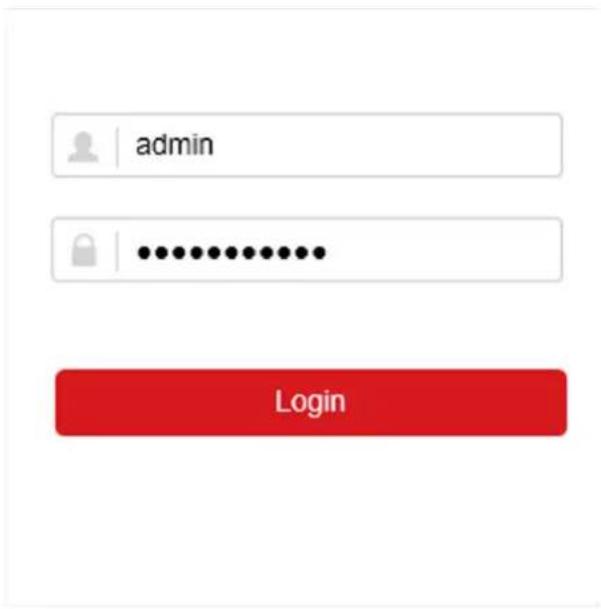
Figure 9-1 Login
- Follow the installation prompts to install the plug-in.

You may have to close the web browser to finish the installation of the plug-in.
9.3 Live View
After login, live view interface shows.
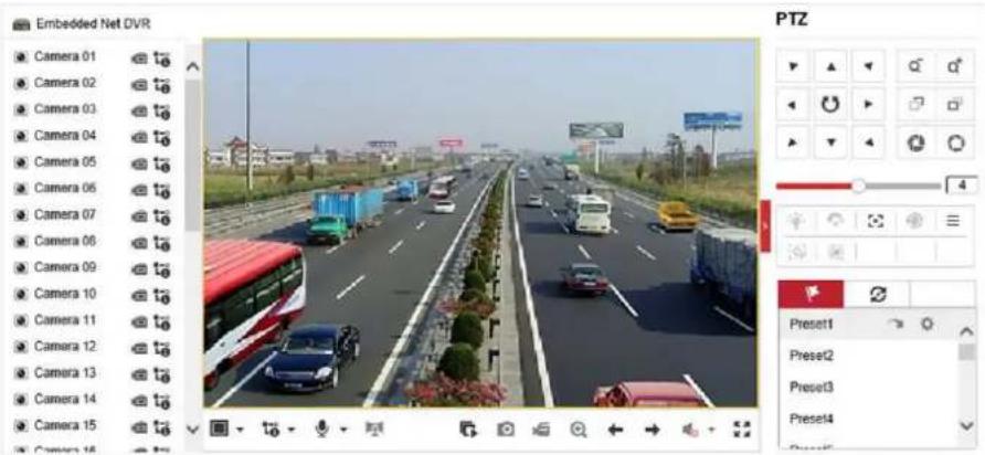
Figure 9-2 Live View
9.4 Playback
Click Playback to enter playback interface.

Figure 9-3 Playback
9.5 Configuration
Click Configuration to enter configuration interface.
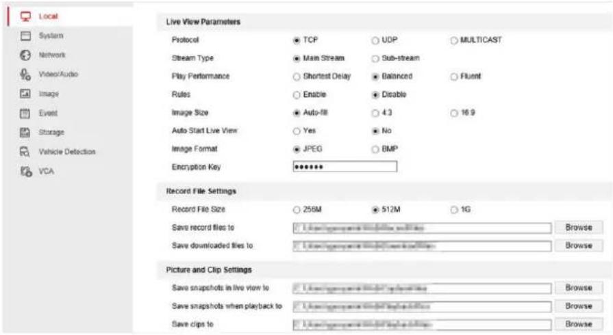
Figure 9-4 Configuration
9.6 Log
Steps
- Go to Maintenance → System → Maintenance → Log.
- Set the search conditions.
- Click Search.
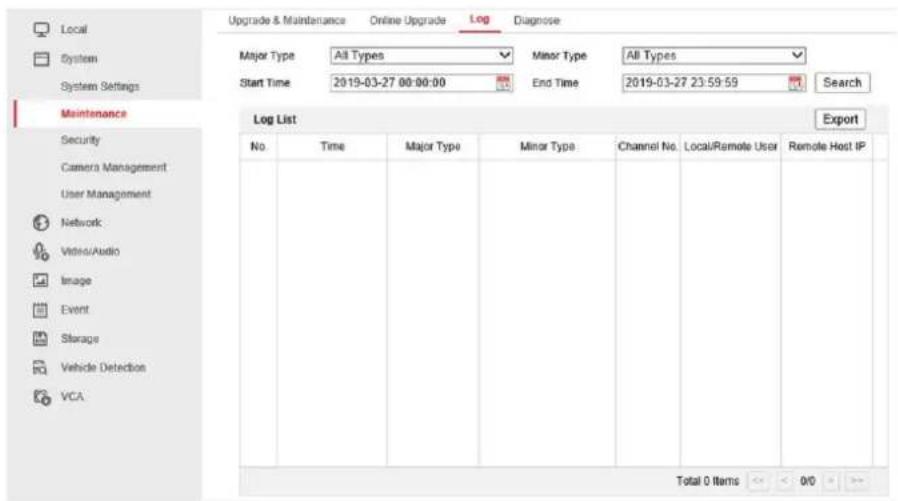
Figure 9-5 Log
Chapter 10 Appendix
10.1 Glossary
Dual-Stream
Dual-stream is a technology used to record high resolution video locally while transmitting a lower resolution stream over the network. The two streams are generated by the DVR, with the main stream having a maximum resolution of 1080P and the sub-stream having a maximum resolution of CIF.
DVR
Acronym for Digital Video Recorder. A DVR is device that is able to accept video signals from analog cameras, compress the signal and store it on its hard drives.
HDD
Acronym for Hard Disk Drive. A storage medium which stores digitally encoded data on platters with magnetic surfaces.
DHCP
Dynamic Host Configuration Protocol (DHCP) is a network application protocol used by devices (DHCP clients) to obtain configuration information for operation in an Internet Protocol network.
HTTP
Acronym for Hypertext Transfer Protocol. A protocol to transfer hypertext request and information between servers and browsers over a network.
PPPoE
PPPoE, Point-to-Point Protocol over Ethernet, is a network protocol for encapsulating Point-to-Point Protocol (PPP) frames inside Ethernet frames. It is used mainly with ADSL services where individual users connect to the ADSL transceiver (modem) over Ethernet and in plain Metro Ethernet networks.
DDNS
Dynamic DNS is a method, protocol, or network service that provides the capability for a networked device, such as a router or computer system using the Internet Protocol Suite, to notify a domain name server to change, in real time (ad-hoc) the active DNS configuration of its configured hostnames, addresses or other information stored in DNS.
Hybrid DVR
A hybrid DVR is a combination of a DVR and NVR.
NTP
Acronym for Network Time Protocol. A protocol designed to synchronize the clocks of computers over a network.
NTSC
Acronym for National Television System Committee. NTSC is an analog television standard used in such countries as the United States and Japan. Each frame of an NTSC signal contains 525 scan lines at 60Hz.
NVR
Acronym for Network Video Recorder. An NVR can be a PC-based or embedded system used for centralized management and storage for IP cameras, IP Domes and other DVRs.
PAL
Acronym for Phase Alternating Line. PAL is also another video standard used in broadcast televisions systems in large parts of the world. PAL signal contains 625 scan lines at 50Hz.
PTZ
Acronym for Pan, Tilt, Zoom. PTZ cameras are motor driven systems that allow the camera to pan left and right, tilt up and down and zoom in and out.
USB
Acronym for Universal Serial Bus. USB is a plug-and-play serial bus standard to interface devices to a host computer.
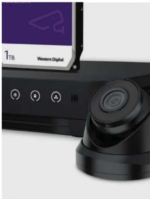
natural_image
Close-up of a black electronic device with a camera lens and control buttons, next to a purple screen labeled '1TB Western Digital' (no readable text beyond branding)
natural_image
Aerial view of a group of people walking on a paved plaza with modern architecture (no visible text or signage)
natural_image
Silhouettes of pedestrians walking on a city street under bright sunlight, no visible text or signage
- Legal Information
- About this Manual
- Trademarks Acknowledgement
- LEGAL DISCLAIMER
- Regulatory Information
- FCC Information
- FCC Conditions
- EU Conformity Statement
- Industry Canada ICES-003 Compliance
- Symbol Conventions
- Safety Instruction
- Preventive and Cautionary Tips
- Contents
- Chapter 1 Startup....1
- Chapter 2 Live View....5
- Chapter 3 Playback....10
- Chapter 4 File Search....15
- Chapter 5 Configuration (Easy Mode) ...... 16
- Network Configuration ...... 19
- Camera Management....22
- Recording Management....30
- Chapter 6 Configuration (Expert Mode)....35
- System Configuration....35
- Network Configuration ...... 38
- Camera Management....43
- Event Configuration....51
- Recording Management....67
- RS-232 Settings....74
- Chapter 7 Maintenance....76
- Chapter 8 Alarm....78
- Chapter 9 Web Operation....79
- Chapter 10 Appendix....83
- Glossary 83
- Chapter 1 Startup
- Activate Your Device
- Before You Start
- Steps
- Warning
- Login
- Set Unlock Pattern
- iNote
- Log in via Unlock Pattern
- Note
- Log in via Password
- Chapter 2 Live View
- GUI Introduction
- PTZ Control
- Configure PTZ Parameter
- PTZ Control Panel Introduction
- Customize Preset
- What to do next
- Customize Patrol
- Click Apply.
- Customize Pattern
- Chapter 3 Playback
- GUI Introduction
- Normal Playback
- Smart Playback
- Do not Play Normal Videos
- Normal Video
- Play Speed of Smart/Custom Video
- Sub-Periods Playback
- Back up Clip
- Chapter 4 File Search
- Search File
- Quick Backup
- Chapter 5 Configuration (Easy Mode)
- System Configuration
- General
- Enable Wizard
- Enable Password
- Enable NTP
- Interval (min)
- NTP Server
- NTP Port
- User
- Add User
- Click OK.
- Set Password Resetting Email
- Reset Password
- Exception
- Set Exception Type
- Network Configuration
- General
- DHCP
- Obtain DNS Automatically
- Guarding Vision
- Set email parameters
- Server Authentication
- User Name
- Password
- SSL/TLS
- Sender
- Sender's Address
- Select Receiver
- Receiver
- Receiver's Address
- Click Apply.
- Camera Management
- Configure Signal Input
- HD/CVBS
- IP
- Network Camera
- Activate Network Camera
- Add Network Camera by Device Password
- Add Network Camera Manually
- Edit Connected Network Camera
- Channel Port
- OSD Settings
- Smart Event
- Motion Detection
- Intrusion Detection
- Line Crossing Detection
- A->B
- B->A
- Configure Arming Schedule
- Configure Alarm Linkage Action
- Click Linkage Action.
- Full Screen Monitoring
- Audible Warning
- Notify Surveillance Center
- Send Email
- PTZ Linkage
- Recording Management
- Storage Device
- Initialize HDD
- Repair Database
- Add Network Disk
- Configure Recording Schedule
- Configure Continuous Recording
- Configure Event Recording
- Edit Schedule
- Continuous
- Event
- Edit Schedule
- Configure Recording Parameter
- Main Stream
- Sub-Stream
- Frame Rate
- Resolution
- Bitrate
- Chapter 6 Configuration (Expert Mode)
- System Configuration
- General
- Language
- Device Name
- Device No.
- Auto Log Out
- Menu Output Mode
- VGA/HDMI Resolution
- Output Standard
- Mouse Pointer Speed
- Live View
- Configure General Parameters
- Live View Mode
- Dwell Time
- Event Output
- Full Screen Monitoring Dwell Time
- Enable Audio Output
- Volume
- Configure Live View Layout
- Click Apply.
- Configure Channel-Zero Encoding
- User
- Network Configuration
- TCP/IP
- Working mode
- NIC Type
- MTU
- DDNS
- NAT
- Ports (More Settings)
- Alarm Host IP/Port
- Server Port
- HTTP Port
- Multicast IP
- RTSP Port
- Output Bandwidth Limit
- Output Bandwidth
- Guarding Vision
- Advanced Settings
- RTSP
- RTSP Authentication Type
- ISAPA
- HTTP
- HTTP Authentication
- IP Camera Occupation Detection
- Camera Management
- Configure Signal Input
- Enhanced IPC Mode
- Enhanced VCA Mode
- 4MP Lite Mode
- 1080P Lite Mode
- Network Camera
- Add Automatically Searched Online Network Camera
- Use Channel Default Password
- Example
- Import/Export IP Camera Configuration File
- Advanced Settings
- H.265 Auto Switch Configuration
- Upgrade
- Channel Default Password Management
- Display Settings
- OSD Settings
- Image Settings
- Exposure
- Day/Night Switch
- Backlight
- Image Enhancement
- Privacy Mask
- Event Configuration
- Normal Event
- Sensitivity
- Video Tampering
- Video Loss
- Alarm Input
- Alarm Output
- Exception
- Smart Event
- Face Detection
- Region Entrance Detection
- Region Exiting Detection
- Loitering Detection
- People Gathering Detection
- Fast Moving Detection
- Parking Detection
- Unattended Baggage Detection
- Click Apply.
- Object Removal Detection
- Audio Exception
- Defocus
- Sudden Scene Change
- Configure Arming Schedule
- Configure Alarm Linkage Action
- Configure Full Screen Monitoring
- Configure Audio Warning
- Configure Email Linkage
- Trigger Alarm Output
- Configure PTZ Linkage
- [D1] IPCamera 01
- Preset No.
- ○ Patrol No.
- ○Pattern No.
- Recording Management
- Configure Recording Schedule
- Configure Recording Parameter
- Enable H.264+
- Audio Source
- Storage Device
- Result
- Configure Storage Mode
- Configure HDD Groups
- Configure HDD Quota
- Advanced Settings
- Overwrite
- Enable HDD Sleeping
- Cloud Storage
- RS-232 Settings
- Console
- Transparent Channel
- Chapter 7 Maintenance
- Restore Default
- Simple Restore
- Factory Defaults
- Restore to Inactive
- Search Log
- Upgrade
- Local Upgrade
- Online Upgrade
- Chapter 8 Alarm
- Set Event Hint
- View Alarm in Alarm Center
- Chapter 9 Web Operation
- Introduction
- Login
- Live View
- Playback
- Configuration
- Log
- Chapter 10 Appendix
- Glossary
- Dual-Stream
- DVR
- HDD
- PPPoE
- DDNS
- Hybrid DVR
- NTP
- NTSC
- NVR
- PAL
- PTZ
- USB
Brand : EtiamPro
Model : EDVR208
Category : Surveillance Camera