D2-BASE-140 - Uncategorized DataVideo - Free user manual and instructions
Find the device manual for free D2-BASE-140 DataVideo in PDF.

| Product Type | Camera Base Plate |
| Brand | DataVideo |
| Model | D2-BASE-140 |
| Dimensions (W x D x H) | 14.0 x 10.0 x 2.5 cm |
| Weight | 0.5 kg |
| Material | Aluminum alloy |
| Compatibility | Teleprompters, cameras with 1/4-20 thread |
| Mounting Thread | 1/4-20 standard tripod screw |
| Load Capacity | Up to 10 kg |
| Color | Black |
| Additional Features | Non-slip rubber pad, bubble level |
| Included Accessories | Mounting screws, hex key |
| Safety | Ensure equipment is securely fastened to prevent tipping |
| Maintenance | Wipe clean with a soft, dry cloth. Avoid solvents. |
| Spare Parts & Repairability | Contact DataVideo support for replacement screws or rubber pads |
Frequently Asked Questions - D2-BASE-140 DataVideo
User questions about D2-BASE-140 DataVideo
0 question about this device. Answer the ones you know or ask your own.
Ask a new question about this device
Download the instructions for your Uncategorized in PDF format for free! Find your manual D2-BASE-140 - DataVideo and take your electronic device back in hand. On this page are published all the documents necessary for the use of your device. D2-BASE-140 by DataVideo.
USER MANUAL D2-BASE-140 DataVideo
PRODUCT INSTRUCTIONS
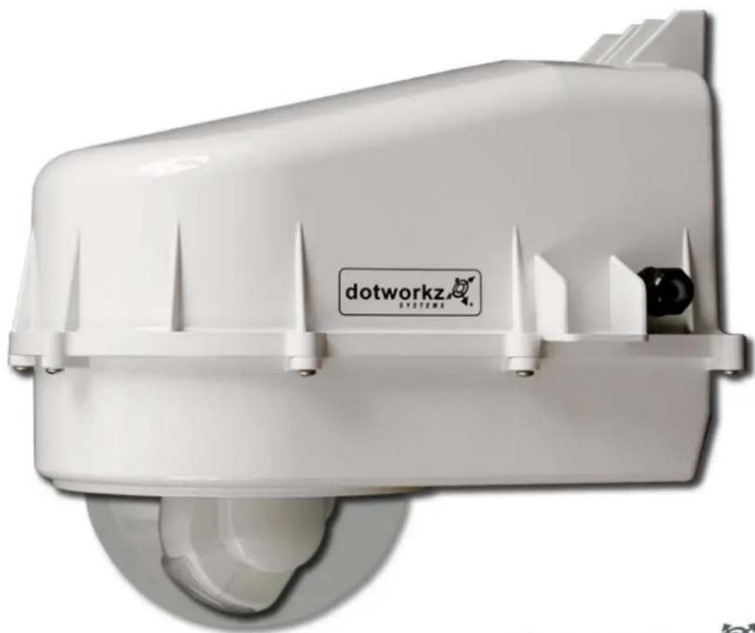
D2 ENCLOSURE SERIES
natural_image
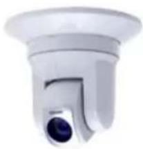
White dotworkz Systems device with a pointed lid and ventilation slots (no visible text or symbols on the device itself)THE INSTALLERS / INTEGRATORS DREAM ENCLOSURE
Table of Contents
Limited Warranty Info ....1
Product Installation Precautions and Warnings 2
D2 Component Checklist for camera installation ....3
Axis 231D/232D Special Bracket....4
Recommended Tools....4
IP Camera Installation (Mounting Brackets) 5-20
Generic Camera....5
Axis 213 & Canon VB-C50i-R 6
Axis 214....7
Axis 231D/232D....8
Axis 233D 9-10
Canon VB-C300....11
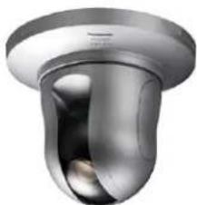
Panasonic NS-202 12
Panasonic HCM381/580/581 & HMC280 13
Sony RZ25N 14
Sony RZ30N 15
Sony RZ50N 16
Sony RX-550N....17
Toshiba WB-21A 18-19
Camera Power Setup 20-23
Standard 12VDC Connector ....20
NON-STANDARD 12VDC CONNECTOR ....21
24VAC....22
Dome Power Setup 23-28
12VDC....24
24VAC....23 & 24
110VAC & 220VAC 23 & 25
CoolDome Installation 26-28
D2 Exploded View 29
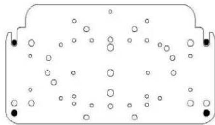
D2 Mounting Template 30
dotworkz SYSTEMS
LIMITED WARRANTY FOR DOTWORKZ SYSTEMS INC. PRODUCTS DOTWORKZ SYSTEMS INC. warrants this Product to be free from defects in material or workmanship, as follows:
| PRODUCT CATEGORY | PARTS | LABOR |
| All Enclosures and Electronics | One (1) Year | One (1) Year |
| Power Supplies | One (1) Year | One (1) Year |
| Accessory Brackets | One (1) Year | One (1) Year |
During the labor warranty period, to repair the Product, Purchaser will either return the defective product; freight prepaid, or deliver it to Dotworkz Systems Inc. San Diego, CA. The Product to be repaired is to be returned in either its original carton or a similar package affording an equal degree of protection with a RMA # (Return Materials Authorization number) displayed on the outer box or packing slip. To obtain a RMA# you must contact our Technical Support Team at 866-575-4689, Dotworkz Systems will return the repaired Product freight prepaid to Purchaser, Dotworkz Systems is not obligated to provide Purchaser with a substitute unit during the warranty period or at any time. After the applicable warranty period, Purchaser must pay all labor and/or parts charges,
The limited warranty stated in these product instructions is subject to all of the following terms and conditions:
- NOTIFICATION OF CLAIMS: WARRANTY SERVICE: If Purchaser believes that the Product is defective in material or workmanship, then written notice
with an explanation of the claim shall be given promptly by Purchaser to Dotworkz Systems but all claims for warranty service must be made within the warranty period. If after Investigation Dotworkz Systems determines that the reported problem was not covered by the warranty, Purchaser shall pay Dotworkz Systems for the cost of investigating the problem at its then prevailing per incident billable rate. No repair or replacement of any Product or part thereof shall extend the warranty period as to the entire Product. The specific warranty on the repaired part only shall be in effect for a period of ninety (90) days following the repair or replacement of that part or the remaining period of the Product parts warranty, whichever is greater
-
EXCLUSIVE REMEDY: ACCEPTANCE: Purchaser's exclusive remedy and Dotworkz System's sole obligation is to supply (or pay for) all labor necessary to repair any Product found to be defective within the warranty period and to supply, at no extra charge, new or rebuilt replacements for defective parts
-
EXCEPTIONS TO LIMITED WARRANTY: Dotworkz Systems shall have no liability or obligation to Purchaser with respect to any Product requiring service during the warranty period which is subjected to any of the following: abuse, improper use: negligence, accident, lightning damage or other acts of God (i.e., hurricanes, earthquakes), modification, failure of the end-user to follow the directions outlined in the product instructions, failure of the end-user to follow the maintenance procedures recommended by the International Security Industry Organization, written in product instructions, or recommended in the service manual for the Product. Furthermore, Dotworkz Systems shall have no liability where a schedule is specified for regular replacement or maintenance or cleaning of certain parts (based on usage) and the end-user has failed to follow such schedule; attempted repair by non-qualified personnel; operation of the Product outside of the published environmental and electrical parameters, or if such Product's original identification (trademark, serial number) markings have been defaced, altered, or removed. Dotworkz Systems excludes from warranty coverage Products sold AS IS and/or WITH ALL FAULTS and excludes used Products which have not been sold by Dotworkz Systems to the Purchaser. All software and accompanying documentation furnished with, or as part of the Product is furnished "AS IS" (i.e., without any warranty of any kind), except where expressly provided otherwise in any documentation or license agreement furnished with the Product.
-
PROOF OF PURCHASE: The purchaser's dated bill of sale must be retained as evidence of the date of purchase and to establish warranty eligibility.
DISCLAIMER OF WARRANTY EXCEPT FOR THE FOREGOING WARRANTIES, DOTWORKZ SYSTEMS HEREBY DISCLAIMS AND EXCLUDES ALL OTHER WARRANTIES, EXPRESS OR IMPLIED, INCLUDING, BUI NOT LIMITED TO ANY AND/OR ALL IMPLIED WARRANTIES OF MERCHANTABILITY, FITNESS FOR A PARTICULAR PURPOSE AND/OR ANY WARRANTY WITH REGARD TO ANY CLAIM OF INFRINGEMENT THAT MAY BE PROVIDED IN SECTION 2-312(3) OF THE UNIFORM COMMERCIAL CODE AND/OR IN ANY OTHER COMPARABLE STATE STATUTE. DOTWORKZ SYSTEMS HEREBY DISCLAIMS ANY REPRESENTATIONS OR WARRANTY THAT THE PRODUCT IS COMPATIBLE WITH ANY COMBINATION OF NON-V1DEOLARM PRODUCTS OR NON-DOTWORKZ SYSTEMS RECOMMENDED PRODUCTS PURCHASER CHOOSES TO CONNECT TO PRODUCT.
LIMITATION OF LIABILITY THE LIABILITY OF DOTWORKZ SYSTEMS, IF ANY, AND PURCHASER'S SOLE AND EXCLUSIVE REMEDY FOR DAMAGES FOR ANY CLAIM OF ANY KIND WHATSOEVER, REGARDLESS OFTHF I FGAI THEORY AND WHFTHFR ARISING IN TORT DP CONTRACT. SHALL NOT RE GREATER THAN THE ACTUAL PURCHASE PRICE OF THE PRODUCT WITH RESPECT TO WHICH SUCH CLAIM IS MADE. IN NO EVENT SHALL DOTWORKZ SYSTEMS BE LIABLE TO PURCHASER FOR ANY SPECIAL, INDIRECT, INCIDENTAL, OR CONSEQUENTIAL DAMAGES OF ANY KIND INCLUDING, BUT NOT LIMITED TO, COMPENSATION, REIMBURSEMENT OR DAMAGES ON ACCOUNT OF THE LOSS OF PRESENT OR PROSPECTIVE PROFITS OR FOR ANY OTHER REASON WHATSOEVER.
IMPORTANT SAFEGUARDS
1 Read Instructions - All the safety and operating instructions should be read before the unit is operated.
2 Retain Instructions - The safety and operating instructions should be retained for future reference.
-
Heed Warnings - All warnings on the unit and in the operating instructions should be adhered to.
-
Follow Instructions - All operating & user instructions should be followed.
-
Electrical Connections - Only a qualified electrician should make electrical connections.
-
Attachments - Do not use attachments not recommended by the product manufacturer as they may cause hazards
-
Cable Runs - All cable runs must be within permissible distance
-
Mounting -This unit must be properly and securely mounted to a supporting structure capable of sustaining the weight of the unit. Accordingly:
a. Installation should be made by a qualified installer.
b. Installation should be in compliance with local codes
c. Care should be exercised to select suitable hardware to install the unit, taking into account both the composition of the mounting surface and the weight of the unit. Be sure to periodically examine the unit and the supporting structure to make sure that the integrity of the installation
Is intact. Failure to comply with the foregoing could result in the unit separating from the support structure and falling, with resultant damages or injury to anyone or anything struck by the failing unit,
| CAUTION: TO REDUCE THE RISK OF ELECTRICAL SHOCK, DO NOT EXPOSE COMPONENTS TO WATER OR MOISTURE | |
 | The lightning flash with an arrowhead symbol, within an equilateral triangle, is intended to alert the user to the presence of non-insulated "dangerous voltage" within the product's enclosure that may be of sufficient magnitude to constitute a risk of electric shock to persons |
 | The exclamation point within an equilateral triangle is intended to alert the user to the presence of important operating and maintenance (servicing) Instructions in the literature accompanying the appliance |
SERVICE
If the unit ever needs repair service, customer should contact Dotworkz Systems +1 (619) 224-LIVE (5483) for return authorization & shipping instructions
UNPACKING
Unpack carefully. Electronic components can be damaged if improperly handled or dropped. If an item appears to have been damaged in shipment, replace it properly in its carton and notify the shipper. Be sure to save
-
The shipping carton and packaging material. They are the safest material in which to make future shipments of the equipment.
-
These Installation and Operating Instructions.
dotworkz SYSTEMS
PRODUCT INSTALLATION PRECAUTIONS – WARNINGS – ADDITIONAL INFORMATION (RETAIN THIS DOCUMENT)
√ For technical questions or product returns – call Dotworkz Customer Service (866-575-4689) 7:30 AM to 4:30 PM (PST). The proper technician will contact you as soon as possible.
- The External Nut on All electrical wire feed Glands must be tightened to create a weather tight seal prior to putting D2 in service. Failure to create this seal may result in water incursion into enclosure. This may lead to electrical shock, product failure and damage to electrical systems installed within enclosure, including but not limited to damage to camera, heater and blower circuitry, cooling circuitry and other systems installed in unit.
- All screws on hinged lower must be tightened to create seal on enclosure. Failure to create this seal may result in water incursion into enclosure. This may lead to electrical shock, failure and damage to electrical systems installed within enclosure, including but not limited to damage to camera, heater and blower circuitry, cooling circuitry and other systems installed in unit.
- Do not over tighten any Screws, Stand Offs, or other fasteners on this unit. Failure to heed this warning will cause damage or failure of the D2 enclosure.
- Be sure to take extra care to Protect Lens of unit prior to and during installation, and during service. Suspension packaging box is a handy platform to protect lens and enclosure, while installing camera and accessory electronics before installation. Failure to protect lens will adversely affect product performance.
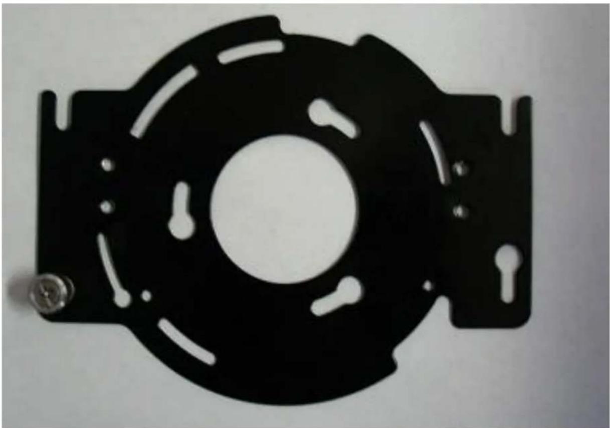
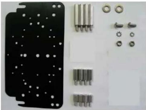
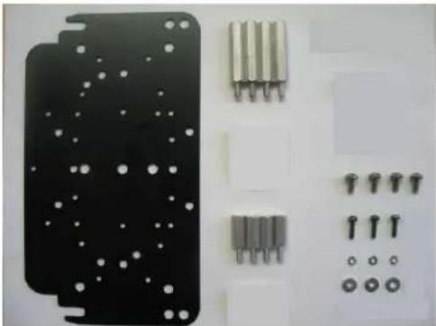
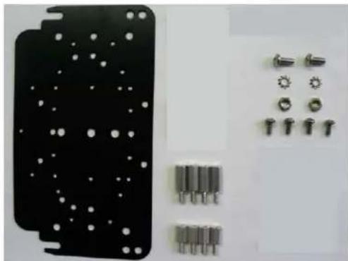
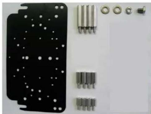
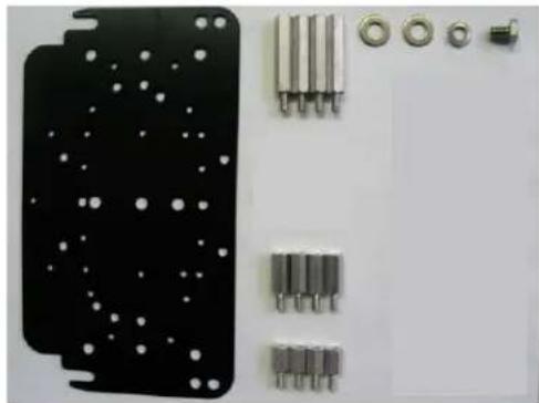
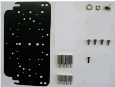
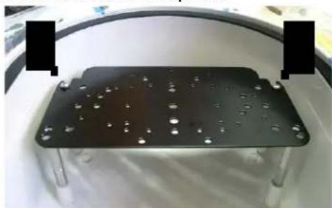
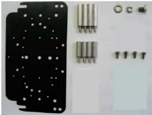
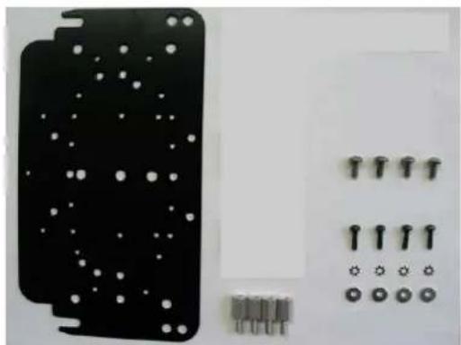
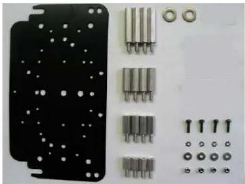
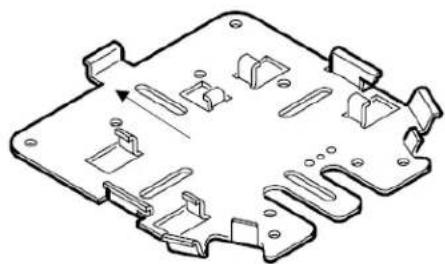
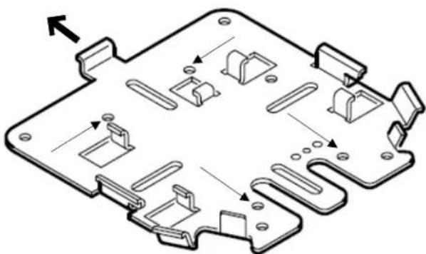
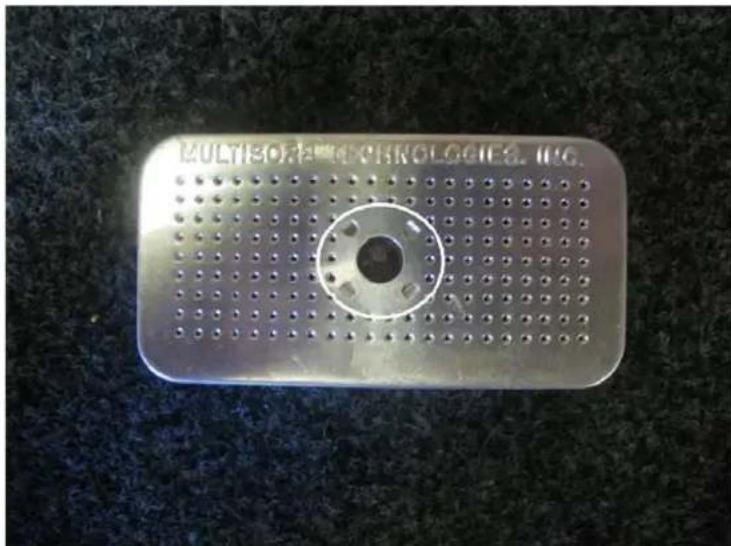
D2 Component Checklist
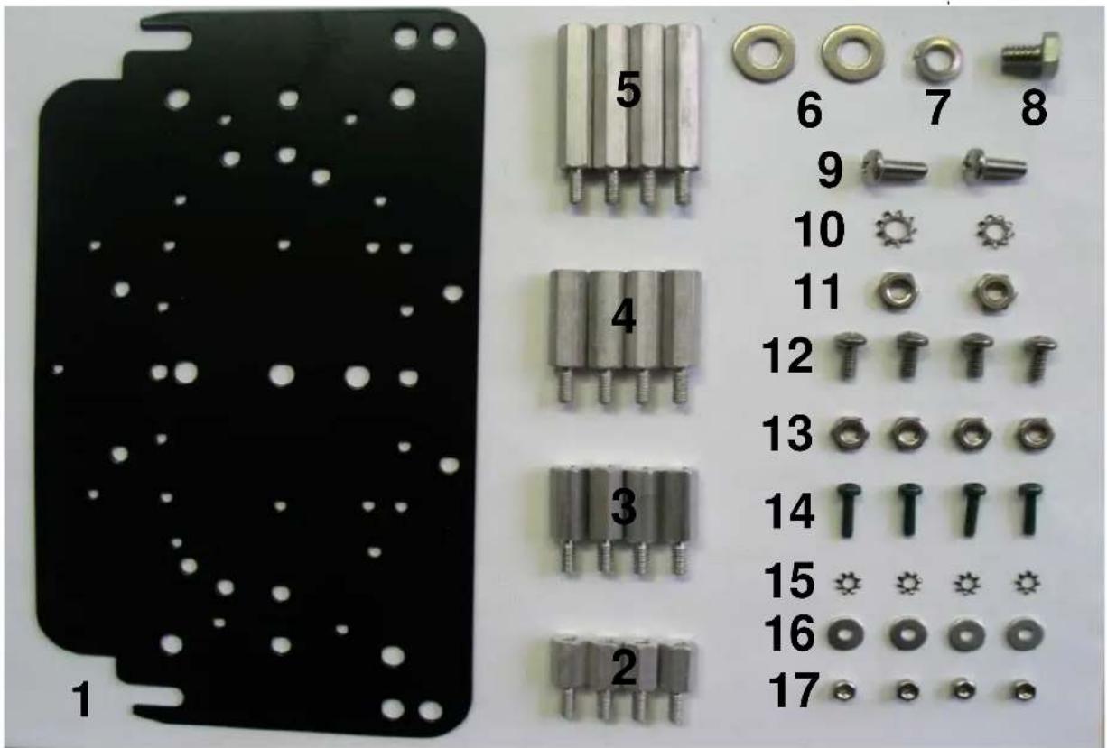
| Number | QTY | DescriptionType | |
| 1 | 1 | Camera Bracket Mount Plate | Aluminum |
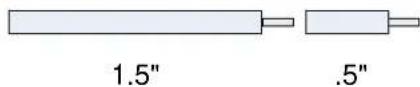
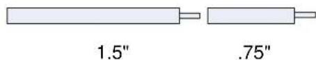
| 2 | 4 | .5" Standoffs (8-32) | Aluminum |
| 3 | 4 | .75" Standoffs (8-32) | Aluminum |
| 4 | 4 | 1.0" Standoffs (8-32) | Aluminum |
| 5 | 4 | 1.5" Standoffs (8-32) | Aluminum |
| 6 | 2 | .25" Washer | Stainless Steel |
| 7 | 1 | .25" Lock Washer | Stainless Steel |
| 8 | 1 | .25"-20 3/8" Long Bolt (7/16 socket/wrench) | Stainless Steel |
| 9 | 2 | #10-32 1/2" Long Screw (Phillips Head) | Stainless Steel |
| 10 | 2 | #10 External Lock Washer | Stainless Steel |
| 11 | 2 | #10-32 Hexnut | Stainless Steel |
| 12 | 4 | #8-32 3/8" Long Screw (Phillips Head) | Stainless Steel |
| 13 | 4 | #8-32 Hexnut | Stainless Steel |
| 14 | 4 | m3-.5 1/2" Long Screw | Aluminum |
| 15 | 4 | m3 External Lock Washer | Stainless Steel |
| 16 | 4 | m3 1/8" Washer | Aluminum |
| 17 | 4 | m3 Locknut | Stainless Steel |
| Next Page | 1 | Axis231/232 Camera mount Plate* | Aluminum |
| *ONLY for Axis 231/232 Specific D2 Enclosure |
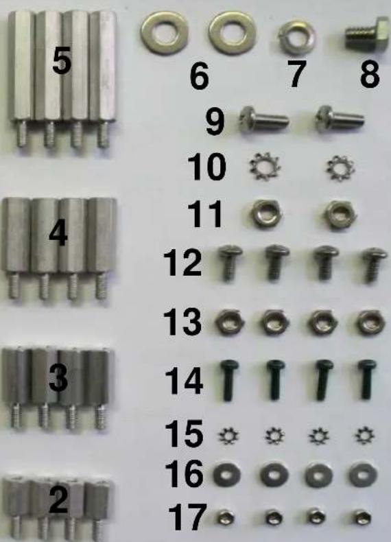
D2 Component Checklist
natural_image
Black metal mechanical component with cutouts and a central hole (no text or symbols visible)Axis 231D/232D Special Camera Bracket
Tools recommended for mounting camera
- #1 & #2 Phillips head screw driver

- #1 or smaller flat head screw driver

- 3/8 Socket wrench, nut driver, or adjustable wrench
- 5/16 Socket wrench, nut driver, or adjustable wrench
- 7/16 Socket wrench, nut driver, or adjustable wrench
- 7/32 Socket wrench, nut driver, or adjustable wrench
- 11/32 Socket wrench, nut driver, or adjustable wrench

natural_image
Collection of mechanical tools including a wrench, screwdriver, and wrench (no text or symbols visible)dotworkz SYSTEMS
Generic Camera Installation
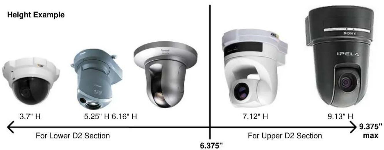
The D2 Enclosure series are designed and engineered for today's most popular standard IP based PTZ cameras. The combination of standoff spacing and camera bracket allows our customers to tailor the D2 Enclosure series to their specific camera needs. We have provided the necessary tools for customization with all of our D2 Enclosure series.
The D2 Enclosure series can accommodate mini-domes and PTZ cameras as tall as 9.375 inches in height. Our standoff combination includes supported heights of 0.50", 0.75", 1.00", 1.25", 1.50", 1.75", 2.00", 2.25", 2.50", 2.75", 3.00", and 3.75". These standoff heights can be applied to upper and lower mount locations based on the height of your camera. Most cameras will often utilize a center screw hole for securing the camera onto the plate.
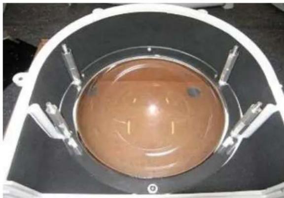
natural_image
Top-down view of a circular brown liquid container with metallic fittings, labeled 'Lower Lens Section' at the bottom (no other text or symbols visible)If your camera has other mounting capabilities, then center the camera on our camera bracket and check to see if it aligns with any of the pre-made holes on the camera bracket. If it does, great you can use the pre-made holes. If it doesn't, you can mark the holes needed and drill them into the camera plate (steel plate).
For power, all of our D2 Environmental Enclosure Series come standard with a 12VDC Barrel plug with a center pin. If you camera does not support this, then check our section on Camera Power Setup (NON-STANDARD CONNECTOR) for details.
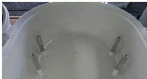
natural_image
Top-down view of a white cylindrical container with four metallic rods inserted (no text or symbols visible)Upper D2 Dome Section
dotworkz SYSTEMS
Installing Camera Bracket
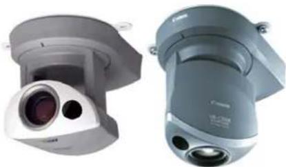
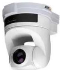
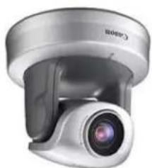
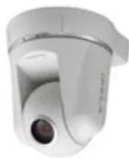
Axis 213 PTZ
Canon VB-C50iR
natural_image
Two identical camera modules shown from front and side views, no text or symbols visible.Required components (see component checklist): Part# 1,2,3,5,6,9,10,& 11
natural_image
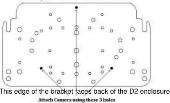
Close-up of electronic components including a black plastic panel, metallic pins, screws, and bolts (no text or symbols visible)This edge nests in arch at front of D2
natural_image
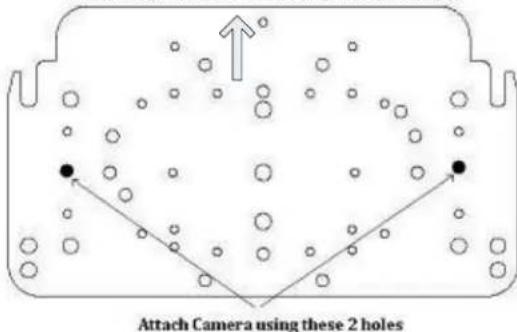
Diagram of a container with bubbles and directional arrows indicating movement or flow (no text or symbols)This edge of the bracket faces back of the D2 enclosure Attach Camera using these 2 holes
-
Install the Axis 213 PTZ or Canon VB-C50iR camera onto the D2 Camera Bracket with (2) #10-32 screws, (2) #10 Lock Washers, and (2) #10 Locknut that are included.
-
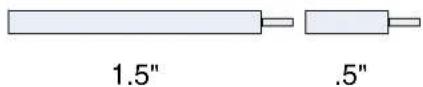
The Axis 213 PTZ or Canon VB-C50iR camera requires a 2" spacing for optimal fit and operation. Use (1) 1.5" standoffs and (1).5" standoffs that are provided to create a 2" standoff. You will need to create 4 of these with the included hardware.
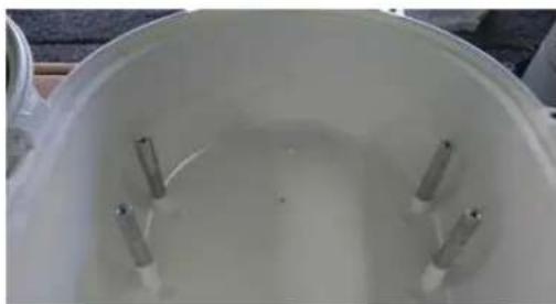
- The 2" standoffs will be inserted on the lower lens portion of the D2.
- Now slide the camera bracket with the camera into place to line up with 4 screws from the standoffs.
natural_image
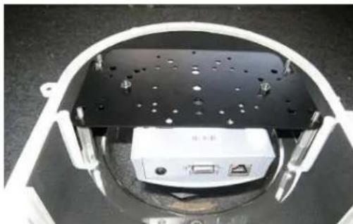
Interior view of a device housing with black panel and white connectors (no visible text or symbols)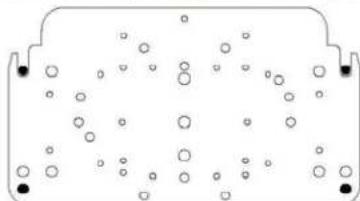
natural_image
Diagram of a container with scattered circular particles inside, no text or symbols present- Secure the plate by using (4) .75" standoffs to lock the bracket in place. The two front location will require the use of (2) .25" washer.
dotworkz SYSTEMS
Installing Camera Bracket
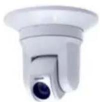
Axis 214 PTZ
natural_image
Exterior view of a white surveillance camera with a lens (no visible text or symbols)Required components (see component checklist): Part # 1,3,5,12,14,15,& 16
natural_image
Electronic component assembly with multiple pins and screws, no visible text or symbolsThis edge nests in arch at front of D2
-
Install the Axis 214 PTZ camera onto the D2 Camera Bracket with (3) m3-.5 screws, (3) m3 external lock washers, and (3) m3 1/8" washer that are included.
-
The Axis 214 PTZ camera requires a 2.25" spacing for optimal fit and operation. Use (1) 1.5" standoffs and (1) .75" standoffs that are provided to create a 2.25" standoff. You will need to create 4 of these with the included hardware.
- The 2.25" standoffs will be inserted on the upper portion of the D2.
-
Now slide the camera bracket with the camera into place to line up with 4 screws holes from the standoffs.
-
Use (4) #8-32 screws (Phillips head) to secure the bracket into place.
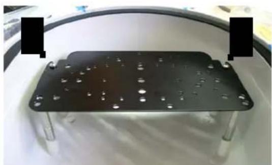
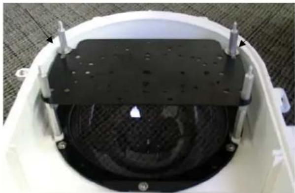
natural_image
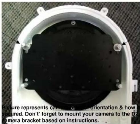
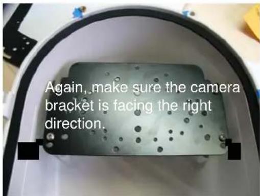
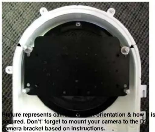
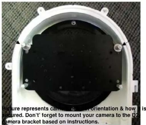
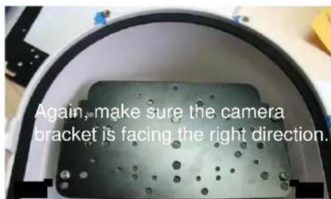
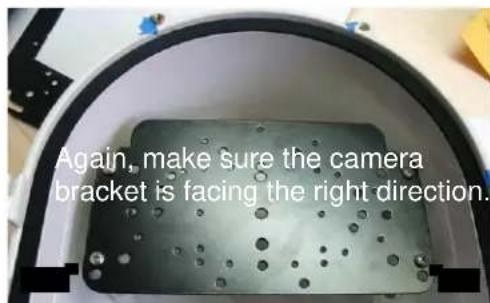
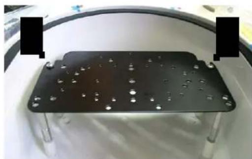
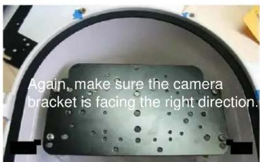
Metallic rectangular plate with embedded holes and mounting feet, displayed on a white surface (no text or symbols visible)Tip: Insert (2) #8-32 screws in the front two standoffs to provide a guide to slide the camera bracket into. The last two corner holes should line up and be secured last.
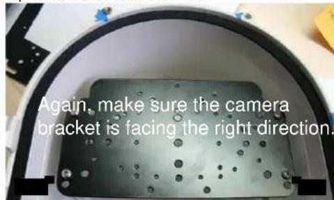
Picture represents camera bracket orientation & how it is secured. Don't forget to mount your camera to the D2 camera bracket based on instructions.
dotworkz SYSTEMS
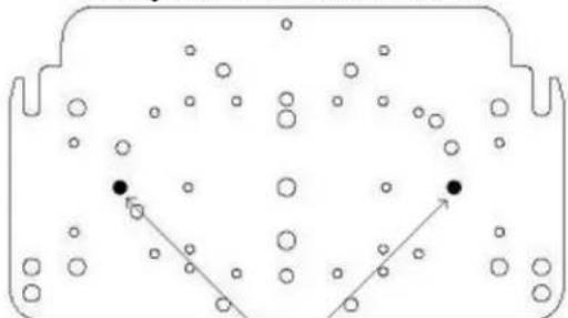
D2 Mounting Instructions for Axis 231D & 232D
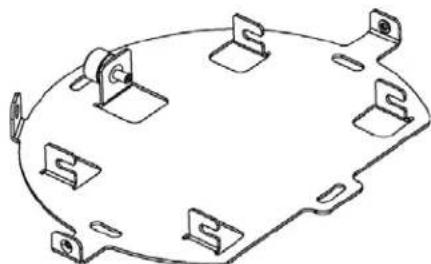
These cameras require the AB-1007 alternate camera bracket shown below, created for cameras with larger mounting bases. It may be ordered directly from Dotworkz, or through your authorized Dotworkz Dealer.
flowchart
graph TD
    A["↑"] --> B["←"]
    B --> C["↓"]
    C --> D["φ"]
    D --> E["+"]
    E --> F["←"]
    F --> G["φ"]
    G --> H["↓"]
    H --> I["φ"]
    I --> J["+"]
    J --> K["←"]
    K --> L["φ"]
    L --> M["↓"]
    M --> N["φ"]
    N --> O["+"]
AB-1007 Camera Bracket (Available upon request)
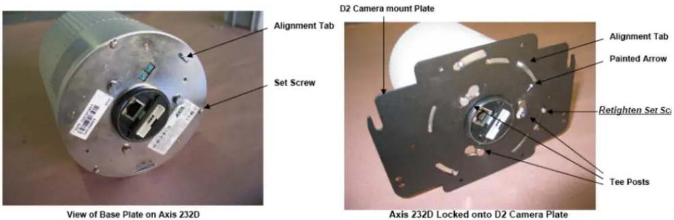
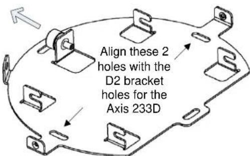
1) Orient Axis 231D/232D to view mounting base as shown in first image.
2) Locate Alignment tab on camera base, and set screw located just below tab as shown in picture. (left)
3) Loosen set screw, backing it out of camera base to approximately 1/8" or more.
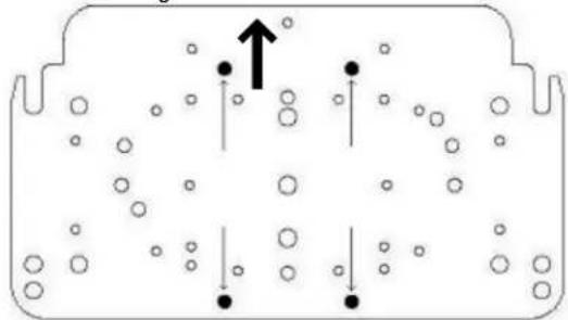
4) Locate Camera mount plate and take note of printed arrow on bottom of plate.
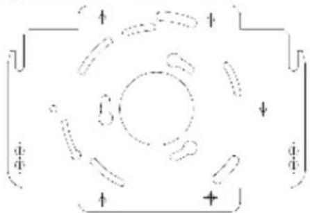
5) Align 3 tee posts on camera base with widest part of corresponding key holes on the D2 camera mount plate; taking note that arrow on plate will align with alignment tab on the camera, before rotating plate.
6) Rotate plate clockwise to set Tee posts into key holes.
7) Finish mounting to the D2 plate by tightening (clockwise) set screw head firmly against D2 camera mount plate.
8) For the proper offset of these cameras into the D2 enclosure's lens. The Axis 231D & 232D will require four 1" stand offs (part ID #4) pre installed onto the corresponding four threaded inserts on the inside front of the D2's upper shell. (see lower right image on pg 5 of D2 Product Instructions)
9) Using wiring harness provided with your camera, and customer provided cat 5 cabling, installer should ready wiring hook up within the D2 enclosure, for final camera placement into the D2 enclosure.
10) Place Axis 231D/ 232D near mouth of enclosure, and hook up harness and cat 5e wires, plugging into camera.
11) Use four #8-32 x 3/8" (part ID #12) pan head machine screws, provided in fastener package of D2's hardware bag, and secure camera mount plate on top of four 1" stand offs mounted in step #8 above. Tighten all 4 of the #8-32 fasteners, securely fastening camera plate into D2.
12) Pre test all clearances, and power connections before closing D2 enclosure. Make adjustments as needed.
dotworkz SYSTEMS
Installing Camera Bracket
Axis 233D PTZ
natural_image
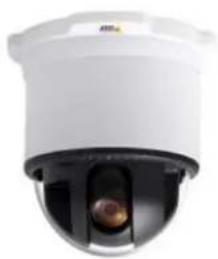
Close-up of a white security camera with a black dome and central lens (no visible text or symbols)Required components (see component checklist): Part # 1,2,3,9,10,11,& 12
natural_image
Electronic component with mounting holes and four metallic screw packages arranged on a white surface (no text or symbols visible)This edge nests in arch at front of D2
This edge of the bracket faces back of the D2 enclosure
natural_image
Technical line drawing of a mechanical bracket or mounting plate (no text or symbols)Axis 233D Ceiling bracket that came with the camera. *This is a required item for installation*
- To install the Axis 233D in the D2 Enclosure we must first install the Axis 233D ceiling bracket adapter that came with the camera onto the D2 camera mounting plate.
Axis 233D Ceiling bracket that came with the camera. *This is a required item for installation*
- Do this by aligning the two holes on the D2 camera bracket with the Axis ceiling bracket adapter. Use (2) #10-32 12 " long screws, (2) #10 lock washers, and (2) #10-32 hex nuts that are included to secure the axis ceiling adapter to the D2 camera bracket.
- Next follow the Axis 233D installation instruction to secure the camera to the ceiling bracket adapter that is now attached to the D2 Camera Bracket.
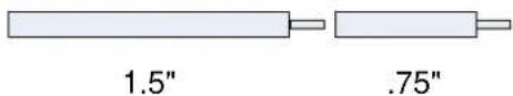
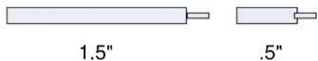
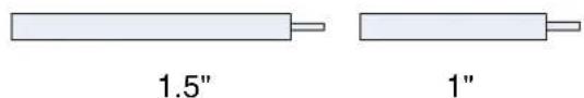
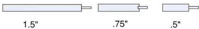
- The Axis 233D PTZ camera requires a 1.25" spacing for optimal fit and operation. Use (1) .75" standoffs and (1) .5" standoffs that are provided to create a 1.25" standoff. You will need to create 4 of these with the included hardware.

.75"

.5"
- The 1.25" standoffs will be inserted on the upper portion of the D2.
dotworkz SYSTEMS
Installing Camera Bracket
Axis 233D PTZ
natural_image
Close-up of a white security camera with a central lens (no visible text or symbols)Continued ....
-
Now slide the camera bracket with the camera into place to line up with 4 screws holes from the standoffs.
-
Use (4) #8-32 screws (Phillips head) to secure the bracket into place.
Tip: Insert (2) #8-32 screws in the front two standoffs to provide a guide to slide the camera bracket into. The last two corner holes should line up and be secured last.
Picture represents camera bracket orientation & how it is secured. Don't forget to mount your camera to the D2 camera bracket based on instructions.
dotworkz SYSTEMS
Installing Camera Bracket
Canon VB-C300
natural_image
Close-up of a silver camera lens with a circular head and lens, no visible text or symbolsRequired components (see component checklist): Part# 1,2,3,5,6,7,& 8
natural_image
Electronic component assembly with metallic pins and screws on a white background (no text or symbols visible)This edge nests in arch at front of D2

This edge of the bracket faces back of the D2 enclosure
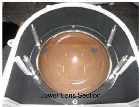
- Install the Canon VB-C300 camera onto the D2 Camera Bracket center hole with (1) .25"-20 3/8" Long Bolt, and (1) .25" Lock Washer that are included.
- The Canon VB-C300 camera requires a 2" spacing for optimal fit and operation. Use (1) 1.5" standoffs and (1).5" standoffs that are provided to create a 2" standoff. You will need to create 4 of these with the included hardware.
- The 2" standoffs will be inserted on the lower lens portion of the D2.

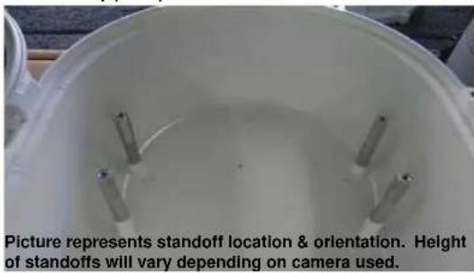
natural_image
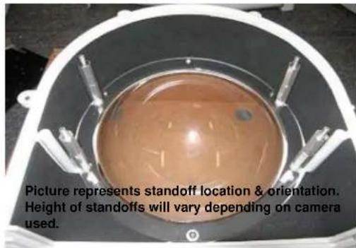
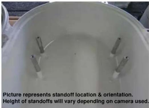
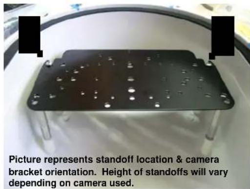
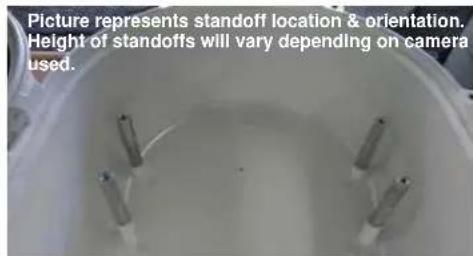
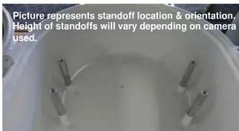
Top-down view of a circular brown object with internal structure, possibly a container or tank, surrounded by metallic components (no visible text or symbols)Picture represents standoff location & orientation. Height of standoffs will vary depending on camera used.
- Now slide the camera bracket with the camera into place to line up with 4 screws from the standoffs.
natural_image
Simple diagram of a container with scattered circles and two black dots at the bottom (no text or symbols)- Secure the plate by using (4).75" standoffs to lock the bracket in place. The two front location will require the use of (2).25" washer.
dotworkz SYSTEMS
Installing Camera Bracket
Panasonic NS-202
natural_image
Close-up of a metallic mechanical component with a curved top and central hole (no visible text or symbols)Required components (see component checklist): Part# 1,2,4,5,6,7,& 8
natural_image
Electronic component with multiple pins and mounting holes, no visible text or symbolsThis edge nests in arch at front of D2
This edge of the bracket faces back of the D2 enclosure
-
Install the Panasonic NS-202 camera onto the D2 Camera Bracket center hole with (1) .25"-20 3/8" Long Bolt, and (1) .25" Lock Washer that are included.
-
The Panasonic NS-202 camera requires a 2.5" spacing for optimal fit and operation. Use (1) 1.5" standoff and (1) 1.0" standoff that are provided to create a 2.5" standoff. You will need to create 4 of these with the included hardware.
- The 2.5" standoffs will be inserted on the lower lens portion of the D2.

natural_image
Top-down view of a circular brown object with internal structure, possibly a container or tank, mounted on a dark base with metal fittings (no visible text or symbols)Picture represents standoff location & orientation. Height of standoffs will vary depending on camera used.
- Now slide the camera bracket with the camera into place to line up with 4 screws from the standoffs.
natural_image
Simple line drawing of a container with scattered circles and two black dots at the bottom (no text or symbols)- Secure the plate by using (4).5" standoffs to lock the bracket in place. The two front location will require the use of (2).25" washer.
dotworkz SYSTEMS
Installing Camera Bracket
Panasonic BB-HCM381/580/581 & KX-HMC280
Required components (see component checklist): Part# 1,2,3,5,6,7,& 8
natural_image
Electronic component assembly with pins, screws, and connectors (no visible text or symbols)This edge nests in arch at front of D2
This edge of the bracket faces back of the D2 enclosure
-
Install the Panasonic camera onto the D2 Camera Bracket center hole with (1) .25"-20 3/8" Long Bolt, and (1) .25" Lock Washer that are included.
-
The Panasonic camera requires a 2.0" spacing for optimal fit and operation. Use (1) 1.5" standoff and (1).5" standoff that are provided to create a 2.0" standoff. You will need to create 4 of these with the included hardware.
- The 2.0" standoffs will be inserted on the lower lens portion of the D2.
natural_image
Top-down view of a circular brown object with internal structure, possibly a container or tank, surrounded by metallic components (no visible text or symbols)Picture represents standoff location & orientation. Height of standoffs will vary depending on camera used.
- Now slide the camera bracket with the camera into place to line up with 4 screws from the standoffs.

natural_image
Simple line drawing of a container with scattered circles and two black dots at the bottom (no text or symbols)- Secure the plate by using (4).75" standoffs to lock the bracket in place. The two front location will require the use of (2).25" washer.

dotworkz SYSTEMS
Installing Camera Bracket
Sony RZ25N
Required components (see component checklist): Part # 1,2,3,12,14,15,& 16
natural_image
Electronic component with mounting holes and four metallic pins arranged on a white surface (no text or symbols visible)This edge nests in arch at front of D2
natural_image
Pure diagram of a symmetrical container with internal vertical lines and scattered circular particles (no text or symbols)This edge of the bracket faces back of the D2 enclosure Attach Camera using these 3 holes
- Install the Sony RZ25N camera onto the D2 Camera Bracket with (3) m3-.5 1/2" Long screw (3) m3 External Lock Washer, and (3) m3 1/8" Washer that are included.
natural_image
Metal mechanical component with mounting holes and a central bolted part (no visible text or symbols)Tip: Don not screw all the way through. Screw them in enough to catch some thread on all three screw locations. Once all three screw catch enough thread, begin tightening one at a time.
- The Sony RZ25N camera requires a 1.25" spacing for optimal fit and operation. Use (1) .75" standoffs and (1) .5" standoffs that are provided to create a 1.25" standoff. You will need to create 4 of these with the included hardware.
- The 1.25" standoffs will be inserted on the upper portion of the D2.
-
Now slide the camera bracket with the camera into place to line up with 4 screws holes from the standoffs.
-
Use (4) #8-32 screws (Phillips head) to secure the bracket into place.

natural_image
Close-up of a black metal plate with evenly spaced holes, mounted on a white surface (no text or symbols visible)Tip: Insert (2) #8-32 screws in the front two standoffs to provide a guide to slide the camera bracket into. The last two corner holes should line up and be secured last.
Picture represents camera bracket orientation & how it is secured. Don't forget to mount your camera to the D2 camera bracket based on instructions.
dotworkz SYSTEMS
Installing Camera Bracket
Sony RZ30N
natural_image
White medical imaging device with digital display and lens (no visible text or symbols)Required components (see component checklist): Part # 1,2,3,6,7,8,12, & 14
natural_image
Electronic component with mounting holes and a barcode patch, no visible text or symbolsThis edge nests in arch at front of D2
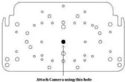
natural_image
Diagram of a container with scattered circles and a central black dot, no text or symbols presentAttach Camera using this hole
This edge of the bracket faces back of the D2 enclosure
-
Install the Sony RZ30N camera onto the D2 Camera Bracket center hole with (1) .25"-20 3/8" Long Bolt, (1) .25" Lock Washer, and (1) .25" Washer that are included.
-
Use (1) m3-.5 12 " long screw in the second corner hole to prevent the Sony RZ30N from moving left and right. The screw will protrude out from the bracket about 14 ". The Sony RZ30 should have a threaded hole that will align with the second corner hole.
natural_image
Close-up of a white electronic device rear panel with ports and indicators (no readable text or symbols)- The Sony RZ30N camera requires a 2.25" spacing for optimal fit and operation. Use (1) 1.5" standoffs and (1) .75" standoffs that are provided to create a 2.25" standoff. You will need to create 4 of these with the included hardware.
- The 2.25" standoffs will be inserted on the upper portion of the D2.
-
Now slide the camera bracket with the camera into place to line up with 4 screws holes from the standoffs.
-
Use (4) #8-32 screws (Phillips head) to secure the bracket into place.
natural_image
Black metal tray with perforated holes and mounting holes, placed on a white surface (no text or symbols visible)Tip: Insert (2) #8-32 screws in the front two standoffs to provide a guide to slide the camera bracket into. The last two corner holes should line up and be secured last.
Picture represents camera bracket orientation & how it is secured. Don't forget to mount your camera to the D2 camera bracket based on instructions.
dotworkz SYSTEMS
Installing Camera Bracket
Sony RZ50N
natural_image
Close-up of a white surveillance camera with a lens (no visible text or symbols)Required components (see component checklist): Part # 1,4,5,6,7,8,& 12
natural_image
Electronic component with black plastic panel, metallic pins, and mounting holes (no visible text or symbols)This edge nests in arch at front of D2

This edge of the bracket faces back of the D2 enclosure
-
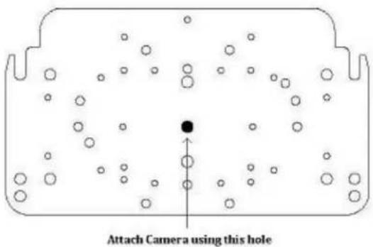
Install the Sony RZ50N camera onto the D2 Camera Bracket center hole with (1) .25"-20 3/8" Long Bolt, (1) .25" Lock Washer, and (1) .25" Washer that are included.
-
The Sony RZ50N camera requires a 2.5" spacing for optimal fit and operation. Use (1) 1.5" standoffs and (1) 1" standoffs that are provided to create a 2.5" standoff. You will need to create 4 of these with the included hardware.
- The 2.5" standoffs will be inserted on the upper portion of the D2.
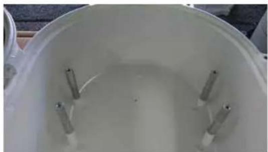
natural_image
Top-down view of a white container with several small cylindrical objects inside (no visible text or symbols)Picture represents standoff location & orientation. Height of standoffs will vary depending on camera used.
-
Now slide the camera bracket with the camera into place to line up with 4 screws holes from the standoffs.
-
Use (4) #8-32 screws (Phillips head) to secure the bracket into place.

natural_image
Black rectangular electronic device with metallic legs and small circular holes, placed on a white surface (no visible text or symbols)Tip: Insert (2) #8-32 screws in the front two standoffs to provide a guide to slide the camera bracket into. The last two corner holes should line up and be secured last.
Picture represents camera bracket orientation & how it is secured. Don't forget to mount your camera to the D2 camera bracket based on instructions.
dotworkz SYSTEMS
Installing Camera Bracket
Sony RX550N
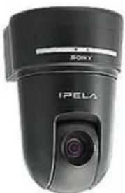
natural_image
Close-up of a black Sony IPELA camera lens (no visible text or symbols on body)Required components (see component checklist): Part # 1,2,12,14,15, & 16
natural_image
Black plastic panel with white dots and multiple screw holes, next to a white wall with four metallic screws (no text or symbols visible)This edge nests in arch at front of D2
natural_image
Diagram of a container with scattered circles and arrows indicating movement or flow (no text or symbols)Attach Camera using these 4 holes.
This edge of the bracket faces back of the D2 enclosure
-
Install the Sony RX550N camera onto the D2 Camera Bracket with (4) m3-.5 12 " long screws, (4) m3 external lock washer, and (4) m3 1/8" washer that are included.
-
The Sony RX550N camera requires a .5" spacing for optimal fit and operation. Use (4) .5" standoffs that are included.

.5"
- The .5" standoffs will be inserted on the upper portion of the D2.
natural_image
Top-down view of a white container with several small cylindrical objects inside, no visible text or symbols.Picture represents standoff location & orientation. Height of standoffs will vary depending on camera used.
-
Now slide the camera bracket with the camera into place to line up with 4 screws holes from the standoffs.
-
Use (4) #8-32 screws (Phillips head) to secure the bracket into place.
natural_image
Black rectangular electronic component with metallic pins and mounting holes, placed on a white surface (no text or symbols visible)Tip: Insert (2) #8-32 screws in the front two standoffs to provide a guide to slide the camera bracket into. The last two corner holes should line up and be secured last.
Picture represents camera bracket orientation & how it is secured. Don't forget to mount your camera to the D2 camera bracket based on instructions.
dotworkz SYSTEMS
Installing Camera Bracket
Toshiba WB21A
natural_image
Close-up of a white security camera with a lens and top mount (no visible text or symbols)Required components (see component checklist): Part # 1,2,3,4,5,6,14,15,16,& 17
natural_image
Collection of electronic components including a black plastic panel, metallic pins, and screw holes (no text or symbols visible)This edge nests in arch at front of D2
natural_image
Diagram of a container with particles and directional arrows indicating movement (no text or symbols)Attach Camera using these 4 holes.
This edge of the bracket faces back of the D2 enclosure
natural_image
Technical line drawing of a mechanical housing or bracket component with cutouts and mounting holes (no text or symbols)Toshiba WB21A Ceiling bracket that came with the camera. *This is a required item for installation*
- To install the Toshiba WB21A in the D2 Enclosure we must first install the Toshiba WB21A ceiling bracket adapter that came with the camera onto the D2 camera mounting plate.
natural_image
Technical line drawing of a mechanical component with multiple slots and mounting holes (no text or symbols)Align these 4 holes with the D2 bracket holes for the Toshiba WB21A
- Do this by aligning the four holes on the D2 camera bracket with the Toshiba ceiling bracket adapter. Use (4) m3-.5 1/2" long screws, (4) m3 external lock washer, (4) m3 1/8" washers, and (4) m3 lock nuts that are included to secure the toshiba ceiling adapter to the D2 camera bracket.
natural_image
Metallic electronic component with four mounting holes and internal circuitry, mounted on a black base (no visible text or symbols)- Next follow the Toshiba WB21A installation instruction to secure the camera to the ceiling bracket adapter that is now attached to the D2 Camera Bracket.
- The Toshiba WB21A PTZ camera requires a 2.75" spacing for optimal fit and operation. Use (1) 1.5" standoff, (1) .75" standoff, and (1) .5" standoffs that are provided to create a 2.75" standoff. You will need to create 4 of these with the included hardware.
dotworkz SYSTEMS
Installing Camera Bracket
Toshiba WB21A
natural_image
Close-up of a white security camera with a lens (no text or symbols visible)Continued ....
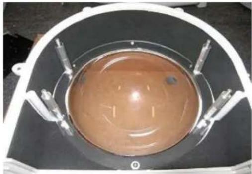
- The 2.75" standoffs will be inserted on the lower portion of the D2.
natural_image
Top-down view of a circular transparent container with a brown liquid, mounted on a black surface with metal fittings (no visible text or symbols)Picture represents standoff location & orientation. Height of standoffs will vary depending on camera used.
- Now slide the camera bracket with the camera into place to line up with 4 screws from the standoffs.
natural_image
Diagram of a container with scattered circles and two side handles, no text or symbols present- Secure the plate by using (4) 1.0" standoffs to lock the bracket in place. The two front location will require the use of (2) .25" washer. See picture.
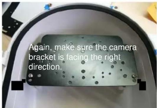
natural_image
Top-down view of a white plastic helmet with black metal plate and circular vent, mounted on a textured floor (no text or symbols visible)Picture represents camera bracket orientation & how it is secured. Don't forget to mount your camera to the D2 camera bracket based on instructions.
dotworkz SYSTEMS
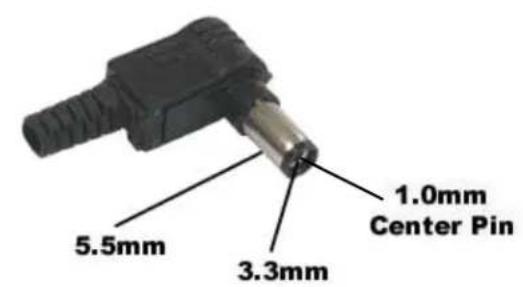
Camera Power Setup (STANDARD 12VDC CONNECTOR)
All D2 environmental enclosures come standard with a 12VDC Right Angle Barrel Plug (3.3mm x 5.5mm with a 1mm center pin) for majority of the IP cameras on the market.
P/Right Angle Standard
Inline version
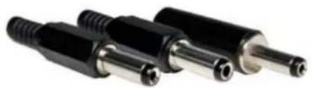
If you IP camera's power connector is different but still accepts up to \~ 13VDC for power, please see our section on Camera Power Setup (NON-STANDARD CONNECTOR) for instructions on how to power your camera. Below are pictures of typical NON-STANDARD CONNECTORS.
natural_image
Close-up of three black plastic connectors with threaded leads (no text or symbols visible)DC plugs with NO center pin
natural_image
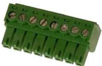
Green terminal block with multiple pin holes and mounting holes (no text or symbols visible)Terminal pin connectors

natural_image
Close-up of a black electronic component with three metallic pins (no visible text or symbols)Terminal connector
If you IP camera's power requirements are for 24 VAC ONLY, please make sure that the D2 Environmental dome that you purchased is a 24VAC version. Cameras that run on 24VAC will not work with the 12VDC and 110-240VAC versions of our D2 Environmental domes.
*NOTE: The only way a 24VAC camera will work on our 12VDC and 110-240VAC dome is if you, the customer, provide a separate power lead into the dome for your camera. We have designed our domes to be simple and efficient when it comes to powering our environmental component and camera. So when it comes to cameras with 24VAC power requirements, we –RECOMMEND-- the 24VAC versions of our Environmental domes for proper installation.
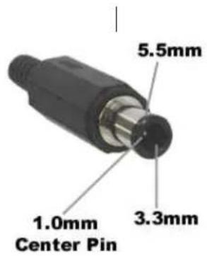
Camera Power Setup (NON-STANDARD 12VDC CONNECTOR)
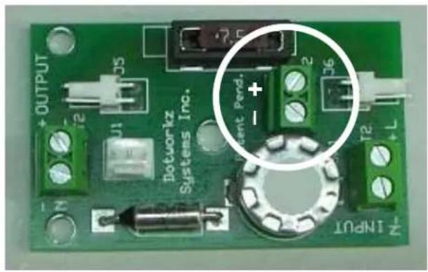
Below are the pictures of the PCB board for the following D2 Environmental Enclosures. The picture identifies where the 12VDC output terminals are. All D2 environmental enclosures come standard with a 12VDC Right Angle Barrel Plug (3.3mm x 5.5mm with a 1mm center pin) for majority of the IP cameras on the market. For the Sony RZ25N and RX550N that uses terminal connectors for their power, you will need to remove the included camera plug and replace it with the 18 AWG gauge wire lead that was provided. Use a mini-flat head screw driver to loosen or tighten the terminals. The positive and negative terminals are printed on the PCB.
For 12VDC IP cameras that utilizes non-standard barrel plugs without a center pin, cut approximately 18-24 inches from the camera power supply. Use a multi-meter to determine the positive and negative leads and attach it to the proper terminals.
*This process is only for cameras that DO NOT take a standard 12VDC Right Angle Barrel Plug (3.3mm x 5.5mm with a 1mm center pin).
D2 Heater-Blower PCB D2 Tornado PCB
D2 Ring of Fire PCB D2 CoolDome PCB
natural_image
Green printed circuit board with labeled components and a magnified inset showing pin connections (no readable text or symbols)dotworkz SYSTEMS
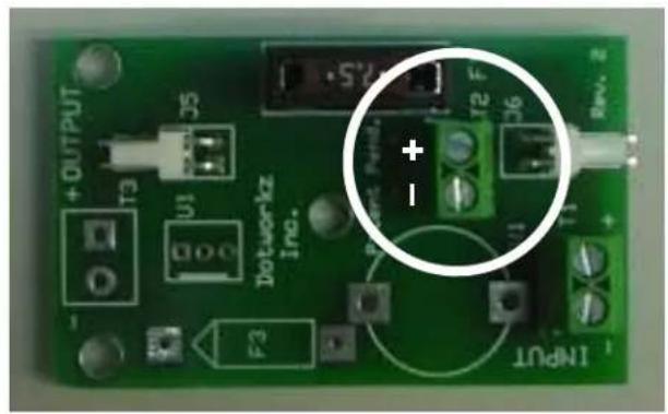
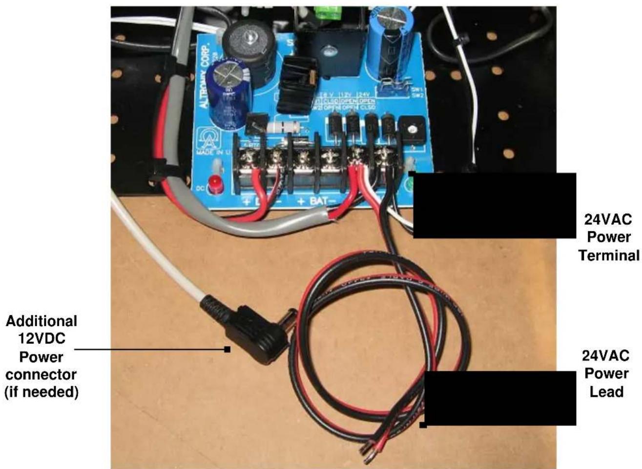
Camera Power Setup (24VAC)
Below is a the pictures of the PCB board for all 24VAC versions of the D2 Environmental Enclosures. The picture identifies where the 24VAC output terminal is and power lead. All of our 24VAC versions of the D2 Environmental Enclosures also have a 12VDC plug if needed.
dotworkz SYSTEMS
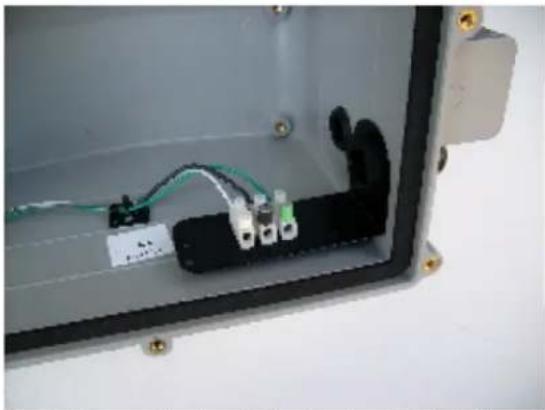
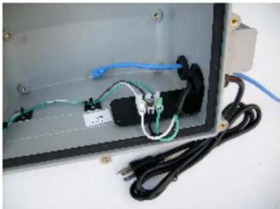
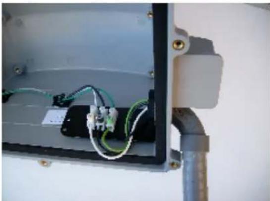
Hooking Up Input/ Line Power to Power Option D2's
Supplied Terminal Blocks on powered D2 options will accept solid or stranded copper wire 14 - 18 gage
High Voltage Hook Up: 110 VAC or 220 VAC
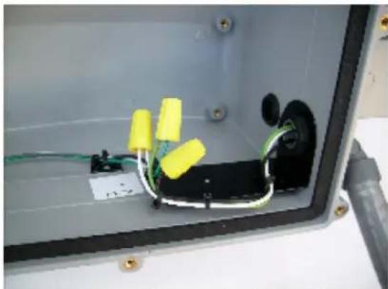
natural_image
Interior view of an open electrical enclosure showing wiring and connectors (no visible text or symbols)Typical Power Block on D2's, Stock on High Voltage Option Heater Blowers, Ring of Fire's, and Tornado
natural_image
Interior view of an open electrical enclosure with visible wiring and connectors (no text or symbols)Hooked Up Optional Power Cord with Customer Supplied Cat 5e Cable and extra Cable Gland Installed
natural_image
Interior view of an electrical enclosure showing wiring and components (no visible text or symbols)Another Power Hook Up Option with 90 deg. Water Tight Flex Conduit Wire Whip (Customer Supplied)
natural_image
Interior view of an open electrical enclosure showing wiring and components (no visible text or symbols)Substituting Wire Nuts (Customer Supplied) for Terminal Block, when Heavy Gage Supply Wire Hook Ups are needed
Low Voltage Hook Up: 12 VDC, 24 VDC/ VAC
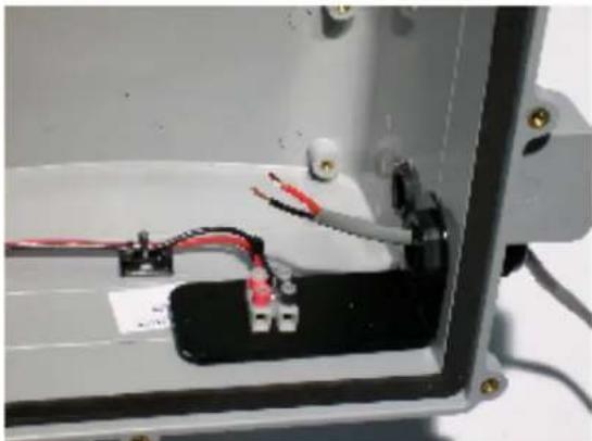
natural_image
Interior view of an open electrical enclosure showing wiring and a battery pack (no text or symbols visible)Low Voltage Wiring, W/ Customer Supplied Wire Ready
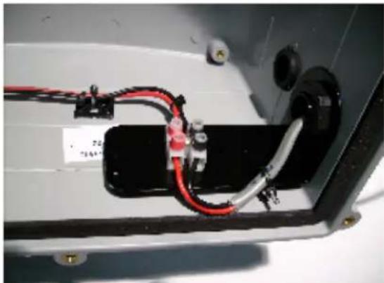
natural_image
Close-up of a mechanical or electronic component with red and black wires, no visible text or symbolsLow Voltage Wiring Clamped into Terminal Block For Very Heavy gage Wiring inputs, Wire Nuts can be Substituted for Terminal Block (See lower right picture)
dotworkz SYSTEMS
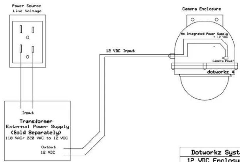
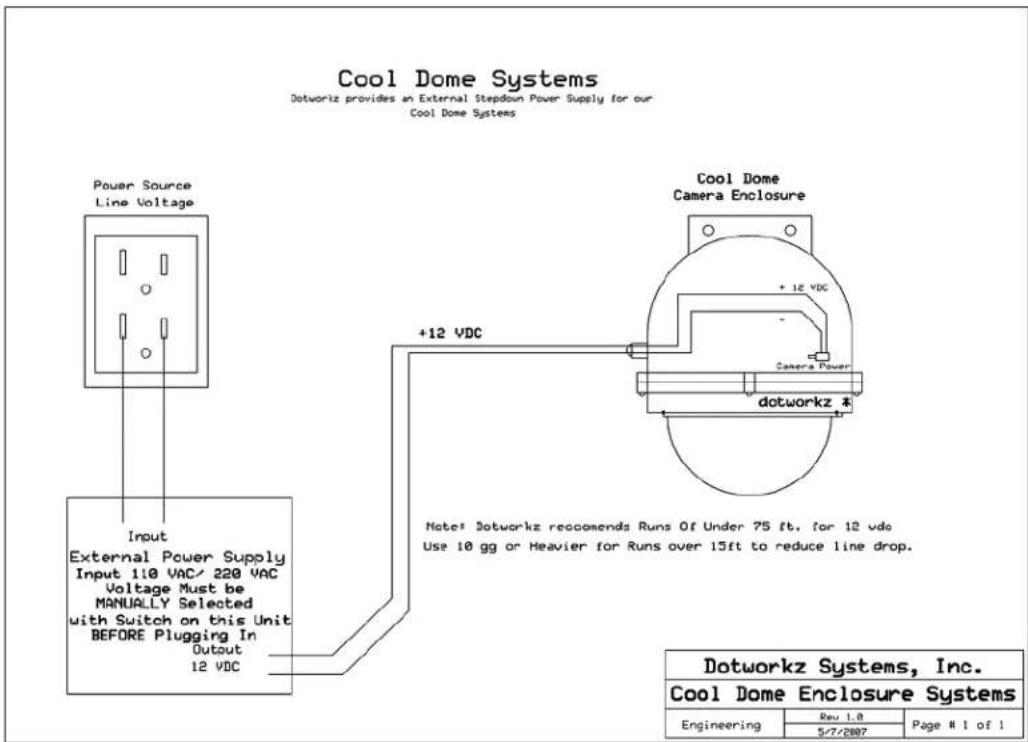
12 YDC Dome Systems
Dolworkz does HOTprovide an integrated Power Supply in our 12 VOC Heater Blower, Dual Blower, and Ring of Fire Systems
| Dotworkz Systems, Inc. | ||
| 12 VDC Enclosure Systems | ||
| Engineering | Rev 1.0 | Page # 1 of 1 |
| 5/7/2007 | ||
24 VAC Dome Systems
Dotworkz provides an integrated Stepdoun Power Supply in our Heater Blower, Dual Blower, and Ring of Fire Systems
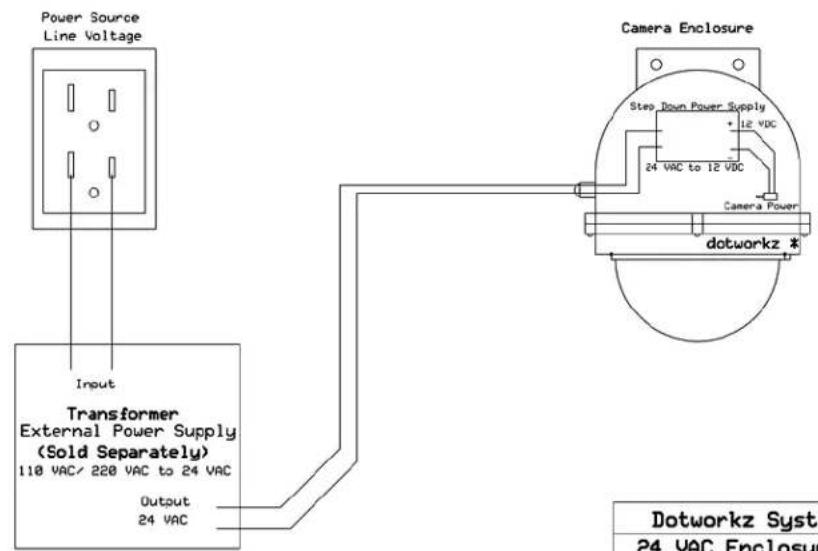
| Dotworkz Systems, Inc. | ||
| 24 VAC Enclosure Systems | ||
| Engineering | Rev 1.0 | Page # 1 of 1 |
| 5/7/2007 | ||
dotworkz SYSTEMS
110 VAC Dome Systems
Networks provides an integrated Stepdown Power Supply in our
Heater Blower, Dual Blower, and Ring of Fire Systems

Note: All Dotworkz High Voltage Systems provide Ground wire for safety. Not shown in this drawing
| Dotworkz Systems, Inc. | ||
| 110 VAC Dome Systems | ||
| Engineering | Rev 1.0 | Page # 1 of 1 |
| 5/7/2007 | ||
220 VAC Dome Systems
Dotworkz provides an integrated Steppoun Power Supply in our Heater Blower, Dual Blower, and Ring of Fire Systems
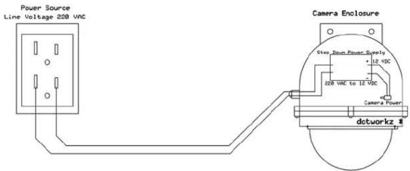
Note: All Dotworkz High Voltage Systems provide Ground wire for safety. Not shown in this drawing
| Dotworkz Systems, Inc. | ||
| 220 VAC Dome Systems | ||
| Engineering | Rev 1.0 | Page # 1 of 1 |
| 5/7/2007 | ||
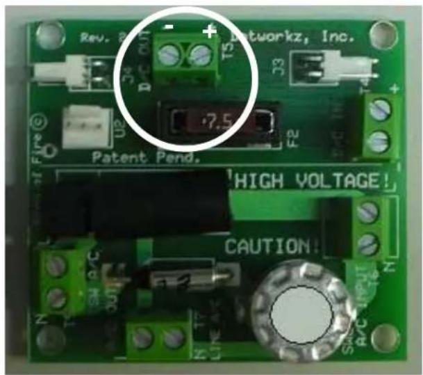
Cool Dome Installation Guidelines: The 400 BTU - D2
Never apply high voltage power directly to the D2 Cool Dome inputs.
The internal circuitry of the D2 was engineered for 12 VDC input ONLY.
But, we do supply each Cool Dome with an external high voltage power supply, the Dotworkz/ MeanWell S-250-12 Power supply, which converts the power to a low voltage 12 VDC output. This allows you to use high voltage to indirectly power the Cool Dome. It is a highly durable, heat tolerant, A/C to D/C Power converter. The input to the provided external power supply follows standard A/C wiring conventions, and is to be mounted nearby indoors, or outdoors in a weather rated enclosure. . It can be powered by single phase 110 VAC, or 220 VAC. It must be manually set to the correct input voltage range (110 VAC or 220 VAC), by moving and setting the slide switch on the side of the power supply, before powering up. The S-250-12 is pictured below on the side of its Terminal Block.
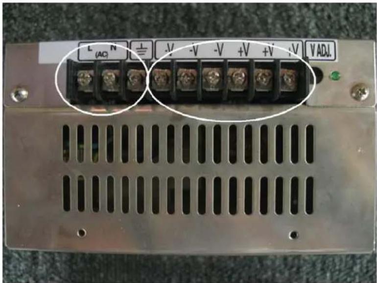
dotworkz SYSTEMS
Please do not attempt to mount the S-250-12 within the Cool Dome itself, due to the large amount of heat created by the power supply, will greatly reduce the cooling effect of the D2 Cool Dome's heat pump.
High Voltage A/C Typical Conventions, single phase:
| Color | Symbol | Description |
| Black | L | Line Conductor, aka: “Hot” wire |
| White | N | Neutral Conductor |
| Green | G | Ground Wire, Chassis Ground |
Low Voltage conventions, D/C, direct current:
| Color | Symbol | Description |
| Red | V+ | Positive conductor |
| Black | V- | Negative conductor |
The output of the S-250-12 external power supply, can be adjusted up and down 10%. It is recommended to keep the voltage at the D2 adjusted to at least 11.5 vdc, but no more than 13.0 vdc. By running the enclosure higher than 13.0 vdc may cause premature component failure. It is best to check and tune the voltage at the Cool Dome with a voltage meter at the time of installation, and use the adjustment screw, located on the S-250-12, to the right side of the terminal screws, to raise or lower the output voltage.
For all outdoor wiring, always use an outdoor rated wiring, or wiring in weather rated conduit, out from power supply, into the Cool Dome. Follow all local and applicable wiring and safety standards.
Please keep D/C wire runs short, to reduce low voltage line drop. Also, the suggested wiring gauge table is provided to further prevent low voltage line drop, and to guide you in selecting the proper wire gauge for the dc run from the power supply to the cool dome.
It is always advisable to use a drip loop on all wiring going directly into the D2 enclosure, to reduce the risk of water entering and damaging internal components. All fittings and seals must be firmly tightened and sealed, before placing the D2 in service.
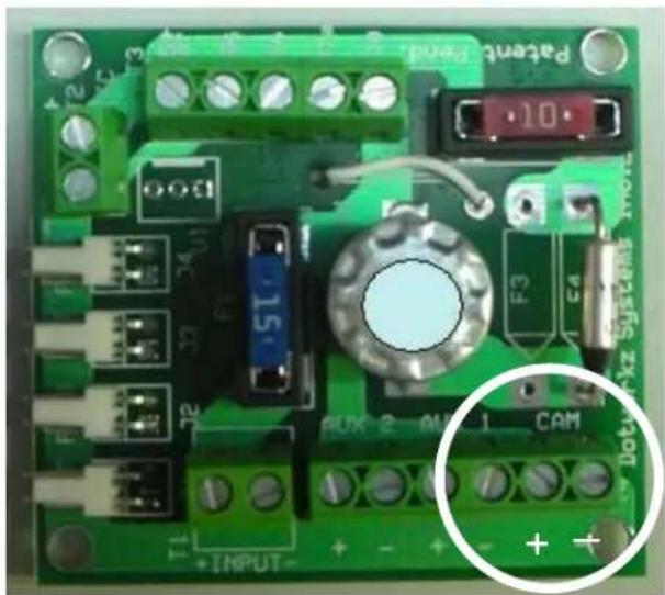
Inside the D2 we have provided a convenient Screw cage clamp style terminal blocks to wire the 12 vdc positive (V+), and the 12 vdc Negative (V-) terminal. Please strip the insulation off the last 3/8" of the wires and fasten wiring securely to terminal, using a small blade screwdriver to tighten the caging mechanism on the terminal blocks. Please be especially attentive to wire using the Proper Polarity, so as not to damage the internal components, or damage your camera within.
12 amps 12 Volts D/C Voltage Drop for Dotworkz D2 Cool Dome
| Wire guageIn AWG (below) | |||||||||
| Distance(ft)>> | 1.0 ft 10.0 | 20.0 30.0 | 40.0 50.0 | 100.0 | |||||
| 4.0 | 0.006 | 0.062 | 0.124 | 0.186 | 0.248 | 0.310 | 0.620 | ||
| 6.0 | 0.010 | 0.098 | 0.196 | 0.294 | 0.392 | 0.490 | 0.980 | ||
| AWG 8.0 | 0.016 | 0.156 | 0.312 | 0.468 | 0.624 | 0.780 | 1.560 | ||
| 10.0 | 0.025 | 0.248 | 0.496 | 0.744 | 0.992 | 1.240 | 2.480 | ||
| 12.0 | 0.040 | 0.400 | 0.800 | 1.200 | 1.600 | 2.000 | 4.000 | ||
| 14.0 | 0.063 | 0.628 | 1.256 | 1.884 | 2.512 | 3.140 | 6.280 | ||
Gauge Multiplier
Vdc drop/ft
Voltage drop (vdc)/ distance (ft)

Acceptable line drop for Wire
Gauge and Distance

Excessive line drop for Wire Gauge and Distance
Above includes 9 amps @ 12 vdc for D2 Cool Dome typical current draw, with 3 amps for max. camera & accessory draw.
Voltage Drop Equation to Determine Minimum Wire Gauge to be Used on D/C run Between the S-250-12 Power Supply to D2 Cool Dome.
Vd = voltage drop for 12vdc run (nominal)
D = distance of run (ft)
Vgm = gauge multiplier (vdc drop, per foot)
$$ \mathrm{Vd} = \mathrm{D} \times \mathrm{Vgm} $$
Where we conservatively try to keep the voltage drop under 1.2 vdc over the low voltage direct current run. These multipliers are approximate, and voltage drop (Vd) is maximum at full 12 amp load at 12 vdc. This voltage drop is under fully loaded condition, when the cooling unit is engaged, and camera and all accessories are on. Voltage drop will be much less, if the current is not at full load.
Reusable Desiccant Canister
The reusable desiccant canister contains forty grams of silica gel. This will prevent moisture buildup inside the Cool Dome. Make sure to remove the canister, located below the camera mount, from its packaging before the Cool Dome is put to use. There is a small window on the canister (white circle). Ensure that the crystals are blue. Occasionally, especially in humid environments, the canister may need to be serviced. If so, the crystals in the window turn pink, and the silica gel is saturated with moisture and can be reactivated by being placed in an oven at 300 °F for three hours or until the crystals turn blue again. The gel can be reactivated virtually an infinite number of times.
Humidity control/ Dessicant cannister should be removed from its foil packaging and secured within enclosure out of the way. The clear window shown in the white circle should be blue when completely dry.
dotworkz SYSTEMS
Exploded View
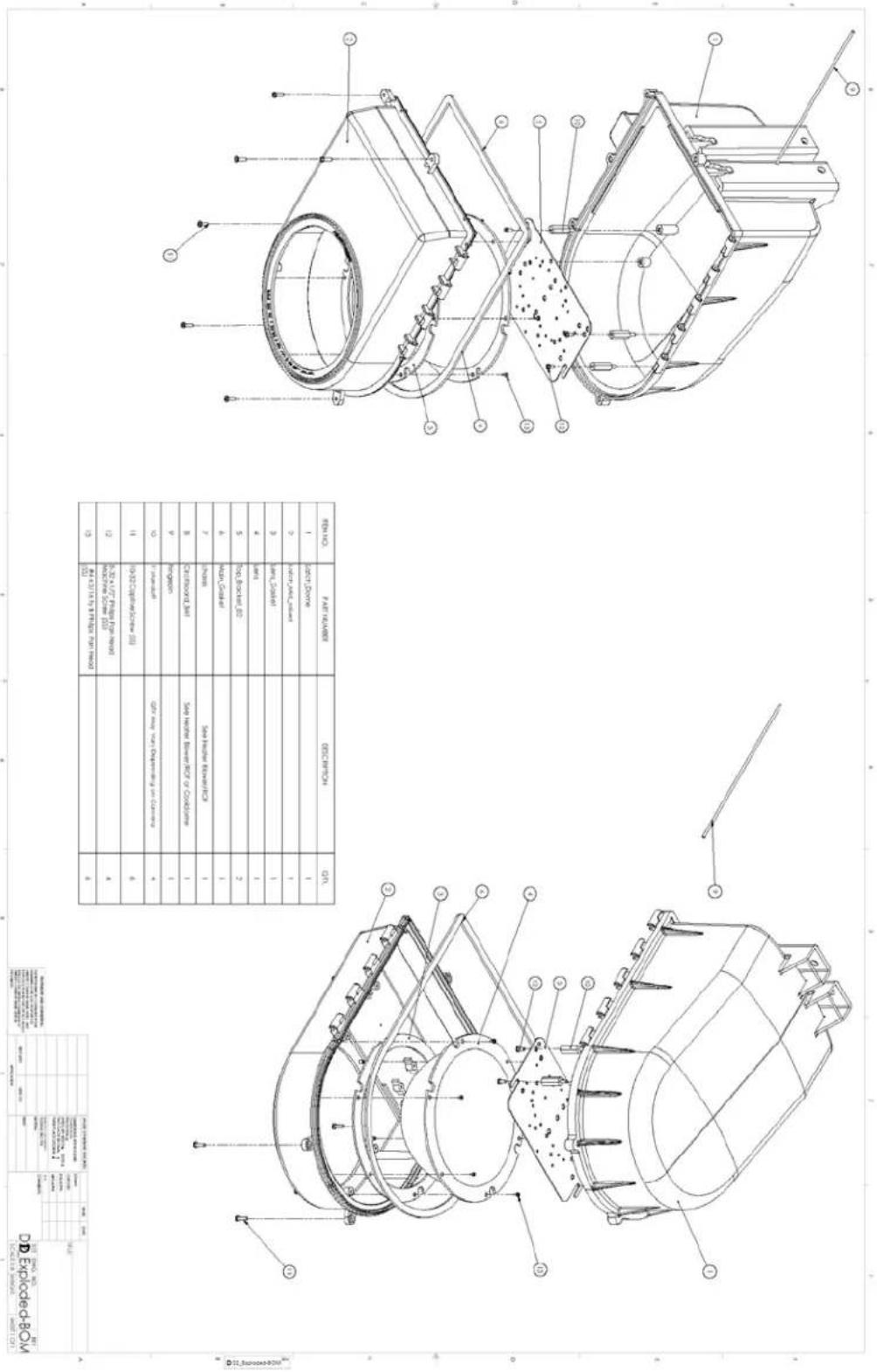
| REPROD. | PARTICULARS | DESCRIPTION | QTY |
| 1 | 20% Durable | 1 | |
| 2 | 30% MIMO Solution | 1 | |
| 3 | 40% MIMO Solution | 1 | |
| 4 | 50% Solid-Blue/EC | 1 | |
| 5 | 60% Solid-Blue/EC | 2 | |
| 6 | 70% Solid | 1 | |
| 7 | 80% Solid | Solid Material Material | 1 |
| 8 | 90% Crystalline, BVI | Side Welter Material/ECF or Condition | 1 |
| 9 | 100% Concentrator | 1 | |
| 10 | 110% Alkaline | ECF may not depend on Climate | 4 |
| 11 | 120% ECF/Satellite (II) | 6 | |
| 12 | 130% 140% Pulsar Fiber (III) | 4 | |
| 13 | 140% 150% 160% Pt/Ceramic (IV) | 6 |
| POTATO (1980) | TOTAL | ||
| 2014 | 2013 | ||
| (10, 10, 10) | (10, 10) | ||
| (10, 10, 10) | (10, 10) | ||
| (10, 10, 10) | (10, 10) | ||
| (10, 10, 10) | (10, 10) | ||
| (10, 10, 10) | (10, 1) | ||
| (10, 10, 10) | (10, 10) | ||
| (10, 10, 10) | (10, 10) | ||
| (10, 10, 10) | (10, 10) | ||
| (10, 10, 10) | (1) | ||
| (10, 10, 10) | (10, 10) | ||
| (10, 10, 10) | (10, 10) | ||
| (10, 10, 10) | (10, 10) | ||
| (10, 10, 10) | (2) | ||
| (10, 10, 10) | (2) | ||
| (10, 10, 10) | (2) | ||
| (10, 10, 10) | (2) | ||
| (10, 10, 10) | (2) | ||
| (10, 10, 1) | (2) | ||

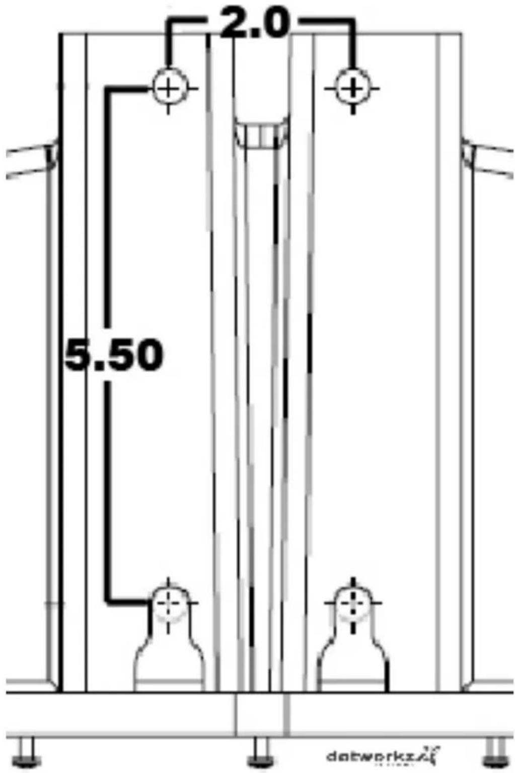
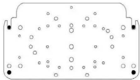
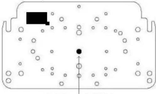
Mounting Template