BB-1 KIT - Électronique de contrôle à distance DataVideo - Free user manual and instructions
Find the device manual for free BB-1 KIT DataVideo in PDF.


| Type de produit | Teleprompter Kit |
| Marque | DataVideo |
| Modèle | BB-1 KIT |
| Dimensions (H x L x P) | Approx. 30 x 40 x 20 cm |
| Poids | Environ 2,5 kg |
| Alimentation | USB 5V ou adaptateur secteur (non inclus) |
| Consommation électrique | Faible, convient pour une utilisation prolongée |
| Matériau | Aluminium et verre optique |
| Type d'écran compatible | Tablette ou moniteur jusqu'à 10 pouces |
| Fonction principale | Réflexion du script pour lecture devant la caméra |
| Angle du verre | 45 degrés |
| Support de montage | Trépied standard (filetage 1/4" et 3/8") |
| Nettoyage | Chiffon doux non pelucheux et nettoyant pour verre |
| Stockage | Dans un endroit sec, à l'abri de la poussière |
| Sécurité | Ne pas exposer à l'humidité, ne pas démonter |
| Pièces détachées disponibles | Verre de rechange, vis de montage |
| Réparabilité | Réparation possible par un technicien qualifié |
| Contenu de la boîte | Cadre du prompteur, verre, housse de transport, manuel |
| Garantie | 1 an (selon le revendeur) |
| Utilisation prévue | Vidéographie professionnelle et amateure |
Frequently Asked Questions - BB-1 KIT DataVideo
User questions about BB-1 KIT DataVideo
0 question about this device. Answer the ones you know or ask your own.
Ask a new question about this device
Download the instructions for your Électronique de contrôle à distance in PDF format for free! Find your manual BB-1 KIT - DataVideo and take your electronic device back in hand. On this page are published all the documents necessary for the use of your device. BB-1 KIT by DataVideo.
USER MANUAL BB-1 KIT DataVideo
WARNINGS AND PRECAUTIONS....3
WARRANTY 4
STANDARD WARRANTY 4
THREE YEAR WARRANTY 4
DISPOSAL 4
INTRODUCTION ....5
SIGN UP TO DV CLOUD ....5
CONNECTING BB-1 TO DV CLOUD 8
STATUS MESSAGES....10
ACCESSING DEVICES REMOTELY....11
CONTROL DATAVIDEO PTC-140 PTZ CAMERAS USING A LAPTOP 11
Using the RMC-300A controller....13
Using the PTZ View Assist app .... 13
Streaming from the PTC-140....14
SRT LATENCY 16
FREQUENTLY-ASKED QUESTIONS......17
SERVICE AND SUPPORT 20
Disclaimer of Product & Services
The information offered in this instruction manual is intended as a guide only. At all times, Datavideo Technologies will try to give correct, complete and suitable information. However, Datavideo Technologies cannot exclude that some information in this manual, from time to time, may not be correct or may be incomplete. This manual may contain typing errors, omissions or incorrect information. Datavideo Technologies always recommend that you double check the information in this document for accuracy before making any purchase decision or using the product. Datavideo Technologies is not responsible for any omissions or errors, or for any subsequent loss or damage caused by using the information contained within this manual. Further advice on the content of this manual or on the product can be obtained by contacting your local Datavideo Office or dealer.
FCC Compliance Statement
This device complies with part 15 of the FCC rules. Operation is subject to the following two conditions:
- This device may not cause harmful interference, and
- This device must accept any interference received, including interference that may cause undesired operation.
Warnings and Precautions

- Read all of these warnings and save them for later reference.
- Follow all warnings and instructions marked on this unit.
- Unplug this unit from the wall outlet before cleaning. Do not use liquid or aerosol cleaners. Use a damp cloth for cleaning.
- Do not use this unit in or near water.
- Do not place this unit on an unstable cart, stand, or table. The unit may fall, causing serious damage.
- Slots and openings on the cabinet top, back, and bottom are provided for ventilation. To ensure safe and reliable operation of this unit, and to protect it from overheating, do not block or cover these openings. Do not place this unit on a bed, sofa, rug, or similar surface, as the ventilation openings on the bottom of the cabinet will be blocked. This unit should never be placed near or over a heat register or radiator. This unit should not be placed in a built-in installation unless proper ventilation is provided.
- This product should only be operated from the type of power source indicated on the marking label of the AC adapter. If you are not sure of the type of power available, consult your Datavideo dealer or your local power company.
- Do not allow anything to rest on the power cord. Do not locate this unit where the power cord will be walked on, rolled over, or otherwise stressed.
- If an extension cord must be used with this unit, make sure that the total of the ampere ratings on the products plugged into the extension cord do not exceed the extension cord rating.
- Make sure that the total amperes of all the units that are plugged into a single wall outlet do not exceed 15 amperes.
- Never push objects of any kind into this unit through the cabinet ventilation slots, as they may touch dangerous voltage points or short out parts that could result in risk of fire or electric shock. Never spill liquid of any kind onto or into this unit.
- Except as specifically explained elsewhere in this manual, do not attempt to service this product yourself. Opening or removing covers that are marked "Do Not Remove" may expose you to dangerous voltage points or other risks, and will void your warranty. Refer all service issues to qualified service personnel.
- Unplug this product from the wall outlet and refer to qualified service personnel under the following conditions:
a. When the power cord is damaged or frayed;
b. When liquid has spilled into the unit;
c. When the product has been exposed to rain or water;
d. When the product does not operate normally under normal operating conditions. Adjust only those controls that are covered by the operating instructions in this manual; improper adjustment of other controls may result in damage to the unit and may often require extensive work by a qualified technician to restore the unit to normal operation;
e. When the product has been dropped or the cabinet has been damaged;
f. When the product exhibits a distinct change in performance, indicating a need for service.
Warranty
Standard Warranty
- Datavideo equipment is guaranteed against any manufacturing defects for one year from the date of purchase.
- The original purchase invoice or other documentary evidence should be supplied at the time of any request for repair under warranty.
- The product warranty period beings on the purchase date. If the purchase date is unknown, the product warranty period begins on the thirtieth day after shipment from a Datavideo office.
- All non-Datavideo manufactured products (product without Datavideo logo) have only one year warranty from the date of purchase.
- Damage caused by accident, misuse, unauthorized repairs, sand, grit or water is not covered under warranty.
• Viruses and malware infections on the computer systems are not covered under warranty. - Any errors that are caused by unauthorized third-party software installations, which are not required by our computer systems, are not covered under warranty.
• All mail or transportation costs including insurance are at the expense of the owner. - All other claims of any nature are not covered.
- All accessories including headphones, cables, batteries, metal parts, housing, cable reel and consumable parts are not covered under warranty.
- Warranty only valid in the country or region of purchase.
- Your statutory rights are not affected.
Three Year Warranty
- All Datavideo products purchased after July 1st, 2017 qualify for a free two years extension to the standard warranty, providing the product is registered with Datavideo within 30 days of purchase.

- Certain parts with limited lifetime expectancy such as LCD panels, DVD drives, Hard Drive, Solid State Drive, SD Card, USB Thumb Drive, Lighting, Non-PCIe Card and third party provided PC components are covered for 1 year.
- The three-year warranty must be registered on Datavideo's official website or with your local Datavideo office or one of its authorized distributors within 30 days of purchase.
Disposal

For EU Customers only - WEEE Marking
This symbol on the product or on its packaging indicates that this product must not be disposed of with your other household waste. Instead, it is your responsibility to dispose of your waste equipment by handing it over to a designated collection point for the recycling of waste electrical and electronic equipment. The separate collection and recycling of your waste equipment at the time of disposal will help to conserve natural resources and ensure that it is recycled in a manner that protects human health and the environment. For more information about where you can drop off your waste equipment for recycling, please contact your local city office, your household waste disposal service or the shop where you purchased the product.

CE Marking is the symbol as shown on the left of this page. The letters "CE" are the abbreviation of French phrase "Conformité Européenne" which literally means "European Conformity". The term initially used was "EC Mark" and it was officially replaced by "CE Marking" in the Directive 93/68/EEC in 1993. "CE Marking" is now used in all EU official documents.
Introduction
The BB-1 remote device control kit allows you to easily control multiple IP enabled devices remotely over the internet. BB-1 works without any special network or firewall configuration.
- A single kit (2 X BB-1) will allow control of up to 5 devices at each end
• Control almost ANY IP controllable device over the internet (PTZ cameras, switchers, recorders etc) - Access multiple remote sites from one BB-1
- Enables several remote production and control workflows
Sign up to dv Cloud
A dv Cloud subscription is required in order for your BB-1 remote device control kit to work, two BB-1 units can be connected to a single dv Cloud Essentials server, six BB-1 units can be connected to a dvCloud Professional server.
- Open a web browser and navigate to www.dvcloud.tv
- Click the 'Sign Up' button below to select the required dv Cloud plan.
Sign Up
- Choose between monthly and annual billing.
Choose Billing Cycle
\$99.00USD Monthly
- Select the server region closest to you and optionally add addition storage for recordings (this can be expanded later at any time).

- Optionally give your server a name, this can make it easier to identify a particular server when you have more than one.
| Additional Information |
| Server Name (Optional) |
- Click the 'Continue' button.

- Click the 'Checkout' button.
- Enter your 'Personal Information', 'Billing Address' and 'Account Security' details or if you have an existing account click 'Already Registered?'
Checkout
Please enter your personal details and billing information to checkout.
Already Registered?
Personal Information

First Name

Last Name

Email Address

+1 Phone Number
Billing Address

Company Name (Optional)

Street Address

Street Address 2

City

-

Postcode

United States

Tax ID (Optional)
- If creating a new account, choose a password.
Account Security

Password

Confirm Password
- Enter your 'Payment Details'.
Payment Details
Total Due Today: \$99.00USD
Please choose your preferred method of payment.

Credit / Debit Card

Card Number

MM/YY
CVV Security Number
- Accept the 'Terms of Service' and click the 'Complete Order' button.

I have read and agree to the Terms of Service
Complete Order

- You order is complete.
Order Confirmation
Thank you for your order. You will receive a confirmation email shortly.
Your Order Number is: 9482657674
Please check your SPAM filter and add noreply@dvcloud.com to your list of safe senders.
- You will receive an order confirmation via email as shown below.

Dear
We have received your order and will be processing it shortly. The details of the order are below:
Order Number: 9482657674
Product/Service: dv Cloud - dv Cloud Professional
Domain: 296092980a6c161
Select your closest server region: San Francisco
- Finally, you will receive the email below confirming your streaming server is ready.

Dear
Thank you for signing up to dv Cloud!
Your dedicated streaming server is ready to go!
You can access it HERE using the following credentials:
User Name: admin
Password: 000000
Please don't forget to change your password after you login!
Getting Started Videos
Click HERE to watch our dv Cloud help videos.
Managing Your Account
You can manage your server(s), subscriptions and invoices by logging into our client area
Connecting BB-1 to dv Cloud
You must first you must connect each BB-1 unit to your dv Cloud server.
- Connect the built in Ethernet port of the BB-1 into your network / router, by default the BB-1 will obtain it IP address automatically using DHCP.
- Connect the USB-to-Ethernet adapter to the USB port of the BB-1 and connect your PC/MAC to the adapter via ethernet.
- Power on the BB-1.
- You PC/MAC will obtain an IP address in the 172.16.2.x range automatically.
- Open a web browser and navigate to 172.16.2.1.
- Login with the username 'admin' and password 'admin'.
Note: If you lose the login credentials for your BB-1 unit, connect a USB mouse to the unit's USB port, then simultaneously press the left and right buttons of the mouse for 10 seconds to reset the BB-1 to its factory default settings. This also resets "Auth Key" and "dv Cloud IP".
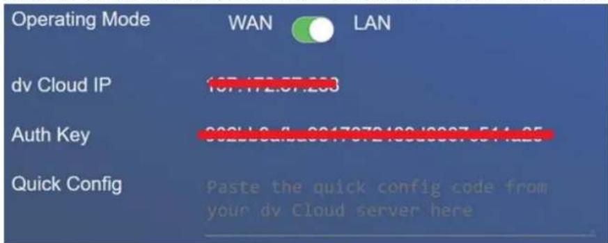
- Click the 'Cloud Setup' tab, you will see the 'Quick Config' field shown below.
- Open a new tab or web browser window and login to your dv Cloud server.
- Select 'BB-1 Devices' from the hardware menu.

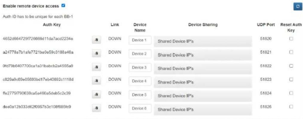
- You will see the screen below, dv Cloud Professional supports up to six BB-1 units, while the Essentials plan supports two BB-1 units. Each BB-1 will connect to dv Cloud using a unique 'Auth Key'.

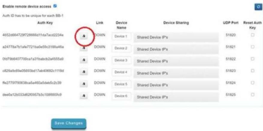
- To connect the first BB-1 unit click the copy button next to the auth key you wish to use. Each auth key is locked to the serial number of the first BB-1 that uses it, to use the auth key on another device you must reset it.
- Return to the BB-1 web UI and paste into the 'Quick Config' field.
Quick Config
Paste the quick config code from your dv Cloud server here
- Save the settings.
- After approximately 10 seconds the status on the BB-1 should show as below. Please check the 'Status' section of this manual for further information.
Status: Remote Link
Name
Device 1
Link
ACTIVE
Last Status
dvCloud is connected
UDP Port
51820
- dv Cloud should show the connection as 'UP' on the 'Devices' tab.

- You can optionally give this BB-1 a new name on dv Cloud, for example DVRD1.
- Repeat steps 1 to 17 for additional BB-1 units.
Status Messages
Name: The device name as set on dv Cloud.
Link: The status will be 'ACTIVE' or 'DISCONNECTED'.
ACTIVE = The connection between the BB-1 and dv Cloud is OK.
DISCONNECTED = The BB-1 is unable to establish a connection with dv Cloud, please see 'Last Status' for more information.
Last Status:
dvCloud is connected = The connection between the BB-1 and dv Cloud is OK.
This Auth key is already locked to another unit! = Each auth key is locked to the serial number of the first BB-1 that uses it, to use the auth key on another device you must reset it on dvcloud.
UDP Port: The UDP port used to connect the BB-1 to dv Cloud, this will be between 51820 and 51825.
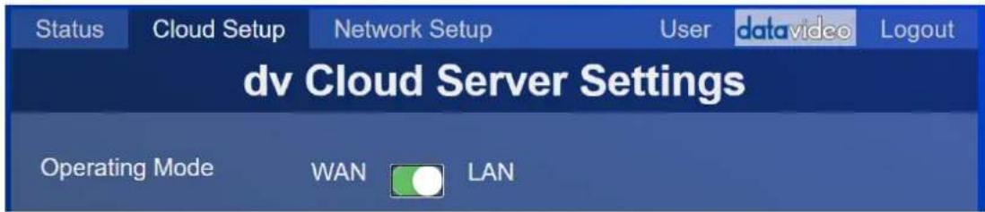
Operating Mode
WAN (Default)
In this mode the BB-1 will provide remote access to devices connected to the same network as the BB-1s built in Ethernet WAN port, it is not required to use a USB to Ethernet adapter at the remote side. Each BB-1 device can control up to five devices.
This mode is ideal when seeking to control devices that are already setup on an existing network.
Example connection diagram

flowchart
graph TD
    A["Camera Control"] -->|USB Ethernet| B["BB-1 Device 1"]
    B --> C["Device 1"]
    C --> D["dvcloud"]
    D --> E["YouTube"]
    D --> F["Facebook"]
    D --> G["Twitch"]
    D --> H["Adobe®"]
    I["PTC-140"] --> J["BB-1 Device 2"]
    J --> K["Device 2"]
    K --> L["RTMP"]
    K --> M["SRT READY"]
LAN
In this mode the BB-1 will provide remote access to devices connected to the USB to Ethernet LAN port, the BB-1 acts as a DHCP server and will automatically assign IP addresses to all connected devices. To connect more than one device simply use an Ethernet switch. Each BB-1 device can control up to five devices.
This mode is ideal for new devices that will be setup for remote control, for example portable flyaway kits.
Example connection diagram
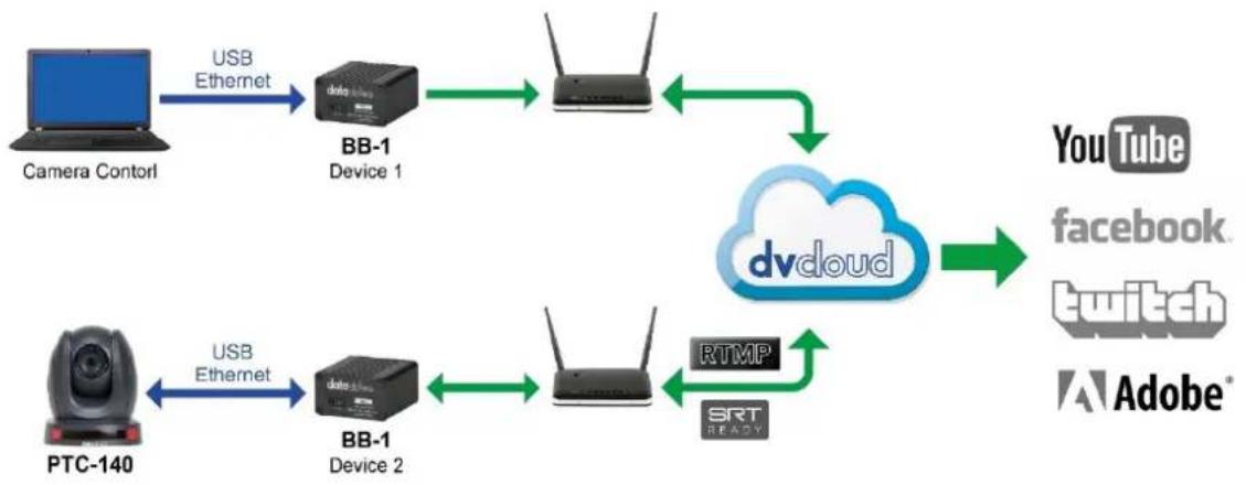
flowchart
graph LR
    A["Camera Contorl"] -->|USB Ethernet| B["BB-1 Device 1"]
    B --> C["Router"]
    D["PTC-140"] -->|USB Ethernet| E["BB-1 Device 2"]
    E --> F["Router"]
    C --> G["dydoud"]
    F --> G
    G --> H["YouTube"]
    G --> I["facebook"]
    G --> J["twitch"]
    G --> K["Adobe"]
    F --> L["RTMP"]
    F --> M["SRT READY"]
Accessing devices remotely
The BB-1 remote device control kit can be used to control almost any equipment that is manually addressable over IP, the following examples cover some common workflows using Datavideo equipment.
Control Datavideo PTC-140 PTZ cameras using a laptop
In these examples we will access a single PTZ camera remotely via a laptop, we assume that you have two BB-1 devices that are already connected to a dv Cloud server.
WAN Mode
Let's assume the BB-1 called 'Device 1' is connected to the router and laptop in location one and the BB-1 called 'Device 2' is connected to the router at location two.

flowchart
graph TD
    A["Camera Contorl"] -->|USB Ethernet| B["BB-1 Device 1"]
    B --> C["Device 1"]
    C --> D["dvdoud"]
    D --> E["YouTube"]
    D --> F["Facebook"]
    D --> G["Twitch"]
    D --> H["Adobe®"]
    I["PTC-140"] --> J["BB-1 Device 2"]
    J --> K["Device 2"]
    K --> L["RTMP"]
    K --> M["SRT READY"]
- At the location one, connect the first BB-1 to your internet router (using the built in Ethernet WAN port) and to the laptop (using a USB to Ethernet adapter).
- At location two, connect the second BB-1 to your internet router (using the built in Ethernet WAN port).
- Ensure the second BB-1 at location two is set to WAN operation mode.

-
Open a web browser and login to your dv Cloud server.
-
Select 'BB-1 Devices' from the hardware menu.

- Click 'Shared Device IP's' to the right of 'Device 2'.
- Datavideo DVIP devices will be automatically detected and can be selected from the drop-down menu.

- Alternatively, if you have a third party PTZ camera you can enter the devices IP address manually. In this example we will assume the camera at location two has a local IP of 192.168.1.12. Enter the IP 192.168.1.12 as shown below.

- Optionally give the device a friendly name such as 'Location 2 PTZ 1'.
- Once you save the settings you will be able to access the camera from the laptop at location one by using the Remote IP (In this case 10.34.2.1).
- Repeat steps 5 to 9 for additional cameras.
You can connect multiple control devices at site one by adding an ethernet switch.
LAN Mode
Let's assume the BB-1 called 'Device 1' is connected to the router and laptop in location one and the BB-1 called 'Device 2' is connected to the router and PTZ camera at location two.

flowchart
graph LR
    A["Camera Contorl"] -->|USB Ethernet| B["BB-1 Device 1"]
    B --> C["Router"]
    D["PTC-140"] -->|USB Ethernet| E["BB-1 Device 2"]
    E --> F["Router"]
    C --> G["dydoud"]
    F --> G
    G --> H["YouTube"]
    G --> I["facebook"]
    G --> J["twitch"]
    G --> K["Adobe®"]
    F --> L["RTMP"]
    F --> M["SRT READY"]
- At location one, connect the first BB-1 to your internet router (using the built in Ethernet WAN port) and to the laptop (using a USB to Ethernet adapter).
- At the location two, connect the second BB-1 to your internet router (using the built in Ethernet WAN port and to the PTZ camera (using a USB to Ethernet adapter). You must ensure the camera is to DHCP / automatic IP mode.
- Ensure the second BB-1 at location two is set to LAN operation mode.
- Open a web browser and login to your dv Cloud server.
- Select 'BB-1 Devices' from the hardware menu.

- Click 'Shared Device IP's' to the right of 'Device 2'.
- You will see the PTZ camera listed in the drop-down list of connected devices, select the PTZ camera.

- Optionally give the device a friendly name such as 'Location 2 PTZ 1'.
- Once you save the settings you will be able to access the camera from the laptop at location one by using the Remote IP (In this case 10.34.2.1).
- Repeat steps 5 to 9 for additional cameras.
You can connect multiple control devices at location one by adding an ethernet switch.
Using the RMC-300A controller
The procedure for using the RMC-300A controller is the same for both the LAN mode and WAN mode examples above.
The RMC-300A can simply be installed in place of the laptop used for control in the examples above, alternatively both the laptop and RMC controller can be connected by adding an ethernet switch.
- Connect the RMC-300A to the BB-1 USB Ethernet adapter (directly or via a switch) and power it on.
- The RMC-300A will automatically detect the Datavideo PTZ cameras that are shared via dvCloud on boot, setup and operation is the same as if the cameras were local to the controller.
If your RMC-300A is not on its factory settings, please check the following:
- Press the 'RMC300A' tab in the top right of the touch screen.
- Tap 'System' in the bottom right of the touch screen.
- Network setting should show an IP address starting with 172.16.2, if it does not then tap the 'Network Setting' field and then ensure the 'DHCP' option is ON.
- Ensure 'Auto DVIP Scan' is ON.
- The RMC-300A will automatically detect the Datavideo PTZ cameras that are shared via dvCloud on boot, setup and operation is the same as if the cameras were local to the controller.
Using the PTZ View Assist app
The procedure for using the PTZ View Assist app on IOS or Android is the same for both the LAN mode and WAN mode examples above. You will need an Ethernet adapter for your Android or IOS device, these are readily available for almost all lightning and USB-C devices.
The IOS or Android device can simply be installed in place of the laptop used for control in the examples above, alternatively both can be connected by adding an ethernet switch.
- Connect the IOS or Android device to the BB-1 USB Ethernet adapter (directly or via a switch) and power it on
- Open the PTZ View Assist app
- The app will automatically detect the Datavideo PTZ cameras that are shared via dvCloud, setup and operation is the same as if the cameras were local to the controller.
Streaming from the PTC-140
Streaming platforms
It is possible for the PTC-140 to stream directly to a single streaming platform, however streaming via dvCloud allows you to stream to up to 25 platforms simultaneously and utilises SRT (Secure Reliable Transport) to ensure your stream works reliably even on poor networks. For more information on SRT please visit
https://www.dvcloud.tv/srt.php.
Create a SRT input channel on dvCloud
- Login to your dvCloud server.
- Click 'Add a video source'.

- Give your video source a name.

- Select SRT as the streaming protocol.

- Click 'Save Channel' at the bottom of the page.
- Click the message displayed at the top of the screen to restart the service.

- We are now ready to configure the PTC-140 encoder.
Stream from the PTC-140 to dvCloud using SRT
- Access the webUI of the PRC-140 camera, please see the PTC-140 manual for more information on accessing the webUI.
- Click 'Configuration' at the top of the page.
- Click 'Stream Publish' at on the left of the page.
- Now go back to your dvCloud server and click the channel name you just created; you will see the SRT IP/Hostname and port.
- Copy the hostname and port into the PTC-140 as show below.

- Set the 'Latency' value to 1000, for more information on the SRT latency parameter please see the 'SRT Latency' section of this manual.
- Click the 'Save' button at the bottom of the page, the stream to dvCloud should start automatically.
- Please see the dvCloud tutorial videos for more information on how to use dvCloud https://www.datavideo.com/us/page/dvcloud-howto-vids
Decoders & Software players
Pull the SRT stream directly from the PTC-140
The PTC-140 has a built in SRT server listening on port 9000, to pull the SRT stream into any SRT capable software player or decoder use the URL below replacing 10.34.1.1 with the remote IP of your PTC-140.
SRT://10.34.1.1:9000
Pull the SRT stream from dvCloud
dvCloud features a built in SRT server, you can connect multiple SRT capable decoders or software players without any additional bandwidth at the camera side.
- Connect the PTC-140 to dvCloud as detailed in the section above.
- Click the 'SRT' button to the right of the channel on dvCloud, this will automatically copy the SRT URL for this channel.
- Paste the URL into the SRT capable software player or decoder of your choice.
Datavideo NVD-3X MK2 Decoders
Datavideo NVD-3X MK2 HDMI/SDI decoders connect seamlessly with dvCloud using just your username and password.
Features:
• Control the NVD-30 MK2 settings from anywhere over the internet.
• Monitor the NVD-30 MK2 from anywhere over the internet.
- Easily link the NVD-30 MK2 to encoders via the cloud.
Please see the NVD-3X MK2 manual for more information.
• Use SRT (secure reliable transport) for reliable low latency point to pint links over the internet.
SRT Latency
You can add from 20 ms to 8000 ms of latency to the SRT stream. Increasing latency gives more time to buffer packets and resend any that got lost in transit to the destination. If the latency value set for the stream is too low and there is packet loss over the network, retransmission of lost packets will not be possible, and the stream quality will suffer.
dvCloud provides several detailed statistics to ensure you set an appropriate SRT latency value:
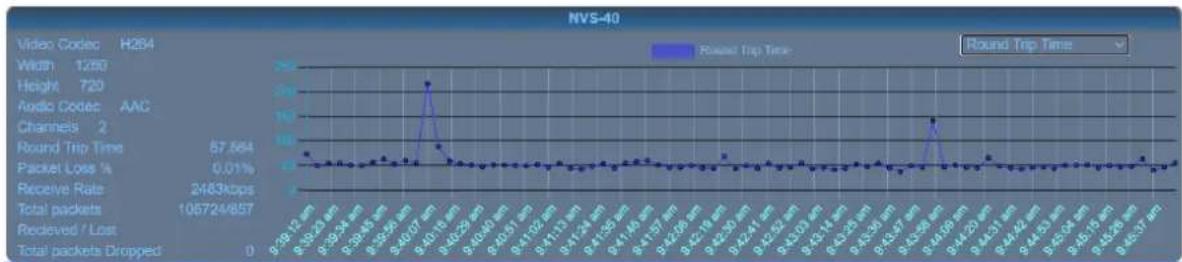
line
| Channel | Round Trip Time | | ------- | --------------- | | 9:39:12 μm | ~0.5 | | 8:39:23 μm | ~0.5 | | 7:39:34 μm | ~0.5 | | 6:39:45 μm | ~0.5 | | 5:39:56 μm | ~0.5 | | 4:30:07 μm | ~25 | | 3:40:16 μm | ~5 | | 2:40:22 μm | ~0.5 | | 1:40:30 μm | ~0.5 | | 0:40:37 μm | ~0.5 | | 9:41:02 μm | ~0.5 | | 8:41:11 μm | ~0.5 | | 7:41:24 μm | ~0.5 | | 6:41:35 μm | ~0.5 | | 5:41:46 μm | ~0.5 | | 4:41:57 μm | ~0.5 | | 3:42:08 μm | ~0.5 | | 2:42:20 μm | ~0.5 | | 1:42:31 μm | ~0.5 | | 0:42:41 μm | ~0.5 | | 9:42:52 μm | ~0.5 | | 8:42:63 μm | ~0.5 | | 7:42:74 μm | ~0.5 | | 6:43:04 μm | ~0.5 | | 5:43:15 μm | ~0.5 | | 4:43:26 μm | ~0.5 | | 3:43:37 μm | ~0.5 | | 2:43:58 μm | ~15 | | 1:43:79 μm | ~0.5 | | 0:43:90 μm | ~0.5 | | 9:43:11 μm | ~0.5 | | 8:43:13 μm | ~0.5 | | 7:43:15 μm | ~0.5 | | 6:43:17 μm | ~0.5 | | 5:43:19 μm | ~0.5 | | 4:43:21 μm | ~0.5 | | 3:43:23 μm | ~0.5 | | 2:43:25 μm | ~0.5 | | 1:43:27 μm | ~0.5 | | 9:43:39 μm | ~0.5 | | 8:43:51 μm | ~0.5 | | 7:43:63 μm | ~0.5 | | 6:43:75 μm | ~0.5 | | 5:43:87 μm | ~0.5 | | 4:43:99 μm | ~0.5 | | 3:44:11 μm | ~0.5 | | 2:44:13 μm | ~0.5 | | 1:44:15 μm | ~0.5 | | 9:44:17 μm | ~0.5 | | 8:44:19 μm | ~0.5 | | 7:44:21 μm | ~0.5 | | 6:44:23 μm | ~0.5 | | 5:44:25 μm | ~0.5 | | 4:44:27 μm | ~0.5 | | 3:44:29 μm | ~0.5 | | 2:44:31 μm | ~0.5 | | 1:44:33 μm | ~0.5 | | 9:44:35 μm | ~0.5 | | 8:44:37 μm | ~0.5 | | 7:44:39 μm | ~0.5 | | 6:44:41 μm | ~0.5 | | 5:44:43 μm | ~0.5 | | 4:44:45 μm | ~0.5 | | 3:44:47 μm | ~0.5 | | 2:44:49 μm | ~0.5 | | 1:44:51 μm | ~0.5 | | 9:44:53 μm | ~0.5 | | 8:44:55 μm | ~0.5 | | 7:44:57 μm | ~0.5 | | 6:44:59 μm | ~0.5 | | 5:44:61 μm | ~0.5 | | 4:44:63 μm | ~0.5 | | 3:44:65 μm | ~0.5 | | 2:44:67 μm | ~0.5 | | 1:44:69 μm | ~0.5 | | 9:44:71 μm | ~0.5 | | 8:44:73 μm | ~0.5 | | 7:44:75 μm | ~0.5 | | 6:44:77 μm | ~0.5 | | 5:44:79 μm | ~0.5 | | 4:44:81 μm | ~0.5 | | 3:44:83 μm | ~0.5 | | 2:44:85 μm | ~0.5 | | 1:44:87 μm | ~0.5 | | 9:44:89 μm | ~0.5 | | 8:44:91 μm | ~0.5 | | 7:44:93 μm | ~0.5 | | 6:44:95 μm | ~0.5 | | 5:44:97 μm | ~0.5 | | 4:44:99 μm | ~0.5 | | 3:45:01 μm | ~0.5 | | 2;45:03 μm | ~0.5 | | 1;45:05 μm | ~0.5 | | 9;45:07 μm | ~0.5 | | 8;45:09 μm | ~0.5 | | 7;45:11 μm | ~0.5 | | 6;45:13 μm | ~0.5 | | 5;45:15 μm | ~0.5 | | 4;45:17 μm | ~0.5 | | 3;45:19 μm | ~0.5 | | 2;45:21 μm | ~0.5 | | 1;45:23 μm | ~0.5 | | 9;45:25 μm | ~0.5 | | 8;45:27μ• Round Trip Time: The round-trip time between the encoder and dvCloud.
- Packet Loss %: The total percentage of packets lost between the encoder and dvCloud NOTE: Most are recovered by retransmission at the source and so do not necessarily result in any artifacts.
• Receive Rate: The total received data rate (Audio + Video).
- Total packets Received / Lost: This is the total number of SRT packets received and reported missing by the dvCloud. For each “hole” detected in the packet sequence, a request to re-transmit the lost packet is sent to the sender. This lost packet may (or may not) be re-covered by the re-transmit request. NOTE: This is the raw number of packets dropped by the network. Most are recovered by retransmission at the source and so do not necessarily result in any artifacts.
- Total packets Dropped: This is the number of SRT packets reported dropped. NOTE: These are packets that have arrived at the dvCloud too late, or that never arrive at all and have not been recovered. Some type of video artifact may result (i.e., a replayed frame or video blocking artifacts). This statistic is very important as it can indicate the SRT latency value is too low or video bitrate is too high.
As a general rule you should monitor the round trip times and set the SRT latency value to 4 * RTT or 2.5 * RTT if low latency is required, if the 'Total packets Dropped' value is increasing the latency value is still too low and must be increased.
Frequently-Asked Questions
This section describes problems that you may encounter while using the BB-1. If you have any questions, please refer to related sections and follow all suggested solutions. If problem still exists, please contact your distributor or the service center.
| No. | Problems | Solutions |
| 1 | How to restore the “username” and “password” for logging into the BB-1 web UI to the factory default values? | If you lose the login credentials for your BB-1 unit, connect a USB mouse to the unit’s USB port, then simultaneously press the left and right buttons of the mouse for 10 seconds to reset the BB-1 to its factory default settings. |
Service & Support
It is our goal to make owning and using Datavideo products a satisfying experience. Our support staff is available to assist you to set up and operate your system. Contact your local office for specific support requests. Plus, please visit www.datavideo.com to access our FAQ section.

Please visit our website for latest manual update.
www.datavideo.com/product/BB-1
datavideo
www.datavideo.com

@DatavideoUSA @DatavideoIndia2016
@DatavideoEMEA @Datavideojapan
@DatavideoTaiwan @DatavideoLatam
@DatavideoAsia @DatavideoBrasil

@DatavideoUSA
@DVTWDVCN

@Datavideo
@Datavideo_EMEA
@Datavideo Taiwan

@DatavideoUSA
@DatavideoEurope
- Disclaimer of Product & Services
- FCC Compliance Statement
- Warnings and Precautions
- Warranty
- Standard Warranty
- Three Year Warranty
- Disposal
- For EU Customers only - WEEE Marking
- Introduction
- Sign up to dv Cloud
- Sign Up
- Checkout
- Personal Information
- Billing Address
- Order Confirmation
- Connecting BB-1 to dv Cloud
- Quick Config
- Status: Remote Link
- Status Messages
- Last Status:
- Operating Mode
- WAN (Default)
- LAN
- Accessing devices remotely
- Control Datavideo PTC-140 PTZ cameras using a laptop
- WAN Mode
- LAN Mode
- Using the RMC-300A controller
- Using the PTZ View Assist app
- Streaming from the PTC-140
- Streaming platforms
- Create a SRT input channel on dvCloud
- Stream from the PTC-140 to dvCloud using SRT
- Decoders & Software players
- Pull the SRT stream directly from the PTC-140
- Pull the SRT stream from dvCloud
- Datavideo NVD-3X MK2 Decoders
- Features:
- SRT Latency
- Frequently-Asked Questions
- Service & Support
Brand : DataVideo
Model : BB-1 KIT
Category : Électronique de contrôle à distance