
SmartRack SRCABLEVRT3FC - Computer and Peripheral Cables Tripp Lite - Free user manual and instructions
Find the device manual for free SmartRack SRCABLEVRT3FC Tripp Lite in PDF.


| Product Type | Vertical Cable Manager |
| Model | SRCABLEVRT3 (SRCABLEVRT3FC) |
| Brand | Tripp Lite |
| Compatible Racks | Open frame racks and enclosures (e.g., SR42UBWD extra-wide enclosure) |
| Number of Cable Trays | 3 |
| Number of Adapter Plates | 3 |
| Material | Steel |
| Color | Black |
| Mounting Method | Toolless mounting buttons and screws |
| Installation Options | Front-facing, side-facing, or PDU manager mounting |
| Dimensions | Designed for 42U enclosures; exact frame dimensions not specified |
| Capacity | High-capacity vertical cable management |
| Door Type | Hinged doors with C-clasps, openable from either side |
| Included Hardware | Mounting brackets, screws (M4 x 6 mm, M4 x 8 mm, M4 x 12 mm), tie plates, cable guides, door hinges |
| Warranty | 5-year limited warranty |
| Manufacturer | Tripp Lite, Chicago, IL, USA |
Frequently Asked Questions - SmartRack SRCABLEVRT3FC Tripp Lite
User questions about SmartRack SRCABLEVRT3FC Tripp Lite
0 question about this device. Answer the ones you know or ask your own.
Ask a new question about this device
Download the instructions for your Computer and Peripheral Cables in PDF format for free! Find your manual SmartRack SRCABLEVRT3FC - Tripp Lite and take your electronic device back in hand. On this page are published all the documents necessary for the use of your device. SmartRack SRCABLEVRT3FC by Tripp Lite.
USER MANUAL SmartRack SRCABLEVRT3FC Tripp Lite
Owner's Manual
SmartRack™ High-Capacity Vertical Cable Manager
Models: SRCABLEVRT3, SRCABLEVRT6 & SRCABLEVRT12

Single-Depth Installation....2
SR42UBWD Installation: Front-Facing.....11
Double-Depth Installation......6
SR42UBWD Installation: Side-Facing.....14
42U Enclosure with PDU Manager Installation Side-Facing.....16
Introduction
SRCABLEVRT models are high capacity cable managers for Tripp Lite open frame racks and rack enclosures. The SRCABLEVRT6 and SRCABLEVRT12 models are designed for use in either a 2-post or 4-post open frame rack, while the SRCABLEVRT3 is designed for installation in the SR42UBWD extra-wide enclosure. Each SRCABLEVRT unit includes three cable trays along with three adapter plates that allow the unit to be mounted to PDU managers in 42U SmartRack enclosures.
Parts List
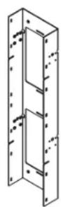
Cable Tray
Frames (3)

Adapter Plates (3)**

Cable Tray Doors (3)*

Cable Tray
Door Straps
(9)**

Cable Guides (12)

Tie Plates (2)* Mounting Buttons (6)


Mounting Brackets (6)*
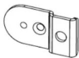
Mounting Brackets (6)**
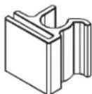
Door Hinges (18) M4 x 6 mm

Flat Head Screws (12) ^†

M4 x 12 mm Pan Head Screws (18) ^

M4 x 8 mm Pan
Head Screws (8)
*SRCABLEVRT6 & SRCABLEVRT12 only.
**SRCABLEVRT3 only.
†SRCABLEVRT3 includes 6 pieces.
^ SRCABLEVRT3 includes 12 pieces.

1111 W. 35th Street, Chicago, IL 60609 USA www.tripplite.com/support

Manufacturing Excellence. Since 1922.
Copyright © 2012 Tripp Lite. All rights reserved. SmartRack is a trademark of Tripp Lite.
Single-Depth Installation (SRCABLEVRT6 & SRCABLEVRT12 only)
Note: Each SRCABLEVRT6 and SRCABLEVRT12 unit includes 3 cable trays. If you install the cable trays in a single-depth configuration, SR2POST (Tripp Lite's 45U 2-post rack) will hold 3 cable trays per side (6 total – requires 2 x SRCABLEVRT6 or SRCABLEVRT12). Always begin installation at the bottom of the rack and work your way to the top.
Step 1 Using (4) M4 x 6 mm flat head screws, attach (2) mounting brackets to (1) cable tray frame.

natural_image
Technical line drawing of a multi-panel cabinet with mounting holes and two hanging sensors (no text or symbols)Step 2 Using (2) M4 x 12 mm pan head screws, attach (2) mounting buttons to the mounting brackets.

natural_image
Technical line drawing of a multi-panel door assembly with mounting holes and a dashed-line connector (no text or symbols)Single-Depth Installation (SRCABLEVRT6 & SRCABLEVRT12 only)
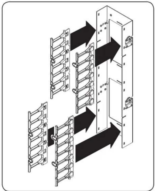
Step 3 Attach (4) cable guides to the cable tray frame. The cable guides slide over the edges of the cable tray frame to form a tight attachment.
flowchart
graph TD
    A["Server Rack"] --> B["Door Lock"]
    B --> C["Back to Panel"]
    C --> D["Back to Window"]
    D --> E["Back to Panel"]
    E --> F["Back to Window"]
    F --> G["Back to Panel"]
    G --> H["Back to Window"]
    H --> I["Back to Panel"]
    I --> J["Back to Window"]
    J --> K["Back to Panel"]
    K --> L["Back to Window"]
    L --> M["Back to Panel"]
    M --> N["Back to Window"]
    N --> O["Back to Panel"]
    O --> P["Back to Window"]
    P --> Q["Back to Panel"]
    Q --> R["Back to Window"]
    R --> S["Back to Panel"]
    S --> T["Back to Window"]
    T --> U["Back to Panel"]
    U --> V["Back to Window"]
    V --> W["Back to Panel"]
    W --> X["Back to Window"]
    X --> Y["Back to Panel"]
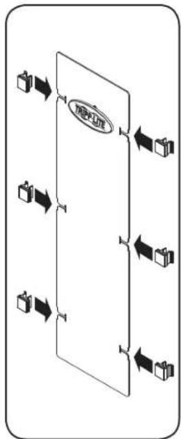
Step 4 Slide (6) door hinges over the edge of (1) cable tray door, then fasten the door to the cable guides via the door hinges' C clasps. After installation, you can release the C clasps on one side of the cable tray door to open it from either side.
flowchart
graph TD
    A["Input Box 1"] --> B["Process Unit"]
    C["Input Box 2"] --> B
    D["Input Box 3"] --> B
    E["Input Box 4"] --> B
    B --> F["Output Box 1"]
    B --> G["Output Box 2"]
    B --> H["Output Box 3"]
    B --> I["Output Box 4"]

flowchart
graph TD
    A["Panel 1"] --> B["Data Bus"]
    B --> C["Column Rack"]
    C --> D["Data Bus"]
    D --> E["Column Rack"]
    E --> F["Data Bus"]
    F --> G["Column Rack"]
    G --> H["Data Bus"]
    H --> I["Column Rack"]
    I --> J["Data Bus"]
    J --> K["Column Rack"]
    K --> L["Data Bus"]
    L --> M["Column Rack"]
    M --> N["Data Bus"]
    N --> O["Column Rack"]
    O --> P["Data Bus"]
    P --> Q["Column Rack"]
    Q --> R["Data Bus"]
    R --> S["Column Rack"]
    S --> T["Data Bus"]
    T --> U["Column Rack"]
    U --> V["Data Bus"]
    V --> W["Column Rack"]
    W --> X["Data Bus"]
    X --> Y["Column Rack"]
Single-Depth Installation (SRCABLEVRT6 & SRCABLEVRT12 only)
Step 5 Align the mounting buttons with the toolless mounting slots on the side of the rack. Insert the mounting buttons through the slots and slide the cable tray downward until secure. Use (4) M4 x 12 mm pan head screws inside of the rack rail to fasten the cable tray in place.

natural_image
Technical line drawing of an electrical enclosure with spring and wall-mounted components (no text or symbols)Step 6 Repeat Steps 1-5 to assemble and mount the other two cable trays, then use (2) tie plates and (8) M4 x 8 mm screws to connect adjacent cable trays for added stability.
- Use (1) tie plate and (4) M4 x 8 mm to connect the bottom cable tray to the middle cable tray.
- Use (1) tie plate and (4) M4 x 8 mm screws to connect the top cable tray to the middle cable tray.
Note: Insert the screws on the opposite side of the cable tray surface from the tie plate, as shown in the diagram. Make sure the flat side of the tie plate faces the cable tray surface so the screws will thread into the tie plate properly.


natural_image
Technical line drawing of a mechanical assembly with no visible text or symbolsSingle-Depth Installation (SRCABLEVRT6 & SRCABLEVRT12 only)
Step 7 (Optional) Repeat Steps 1-6 to install another set of cable trays on the other side of the rack. (A single-depth installation on both sides of the rack requires 2 x SRCABLEVRT6 or SRCABLEVRT12.)

Note: SRCABLEVRT6 is shown. The cable tray frames and doors of the SRCABLEVRT12 are wider, but installation is identical.
Double-Depth Installation (SRCABLEVRT6 & SRCABLEVRT12 only)
Note: Each SRCABLEVRT6 and SRCABLEVRT12 unit includes 3 cable trays. If you install the cable trays in a double-depth configuration, SR2POST (Tripp Lite's 45U 2-post rack) will hold 6 cable trays per side (12 total – requires 4 x SRCABLEVRT6 or SRCABLEVRT12). Always begin installation at the bottom of the rack and work your way to the top.
Step 1 Using (4) M4 x 6 mm flat head screws, attach (2) mounting brackets to (2) cable tray frames. (The brackets will span the frames to connect them.)

natural_image
Technical line drawing of a mechanical assembly with mounting holes and a shaft (no text or symbols)Step 2 Using (2) M4 x 12 mm pan head screws, attach (2) mounting buttons to the mounting brackets.

natural_image
Technical line drawing of a mechanical assembly with mounting holes and a sliding mechanism (no text or symbols)Double-Depth Installation (SRCABLEVRT6 & SRCABLEVRT12 only)
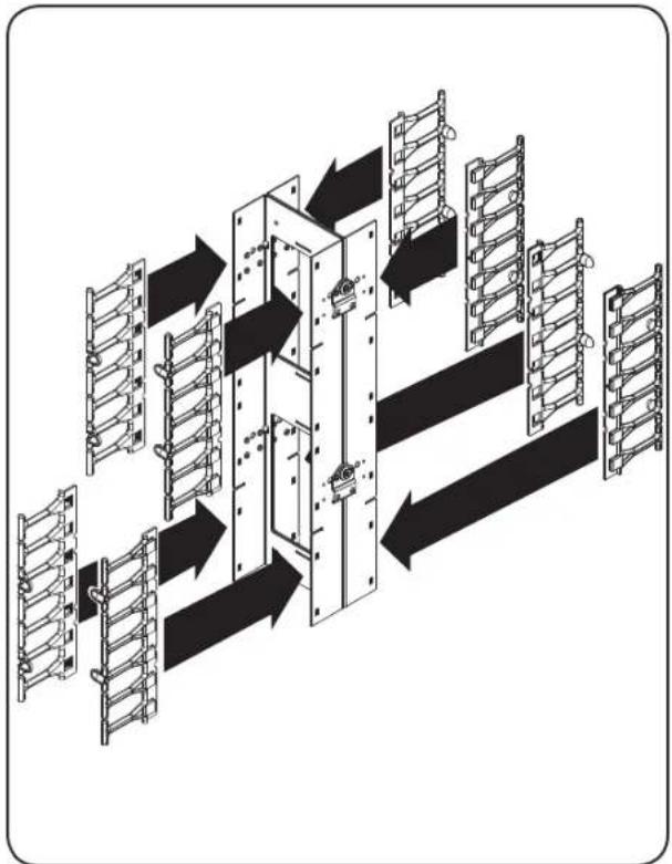
Step 3 Attach (8) cable guides to the cable tray frames. The cable guides slide over the edges of the cable tray frames to form a tight attachment.
flowchart
graph TD
    A["Top Ladder 1"] --> B["Intermediate Panel 1"]
    B --> C["Top Panel 2"]
    C --> D["Bottom Panel 3"]
    D --> E["Final Panel 4"]
    style A fill:#f9f,stroke:#333
    style E fill:#bbf,stroke:#333
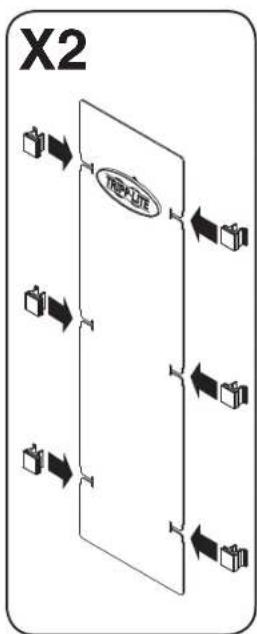
Step 4 Slide (6) door hinges over the edge of (1) cable tray door, then fasten the door to the cable guides via the door hinges' C clasps. Repeat for the other cable tray. After installation, you can release the C clasps on one side of the cable tray door to open it from either side.
flowchart
graph TD
    A["Input Box 1"] --> B["NEKLINE"]
    C["Input Box 2"] --> B
    D["Input Box 3"] --> B
    E["Input Box 4"] --> B
    B --> F["Output Box 1"]
    B --> G["Output Box 2"]
    B --> H["Output Box 3"]

Double-Depth Installation (SRCABLEVRT6 & SRCABLEVRT12 only)
Step 5 Align the mounting buttons with the toolless mounting slots on the side of the rack. Insert the mounting buttons through the slots and slide the cable trays downward until secure. Use (4) M4 x 12 mm pan head screws inside of the rack rail to fasten the cable trays in place.

natural_image
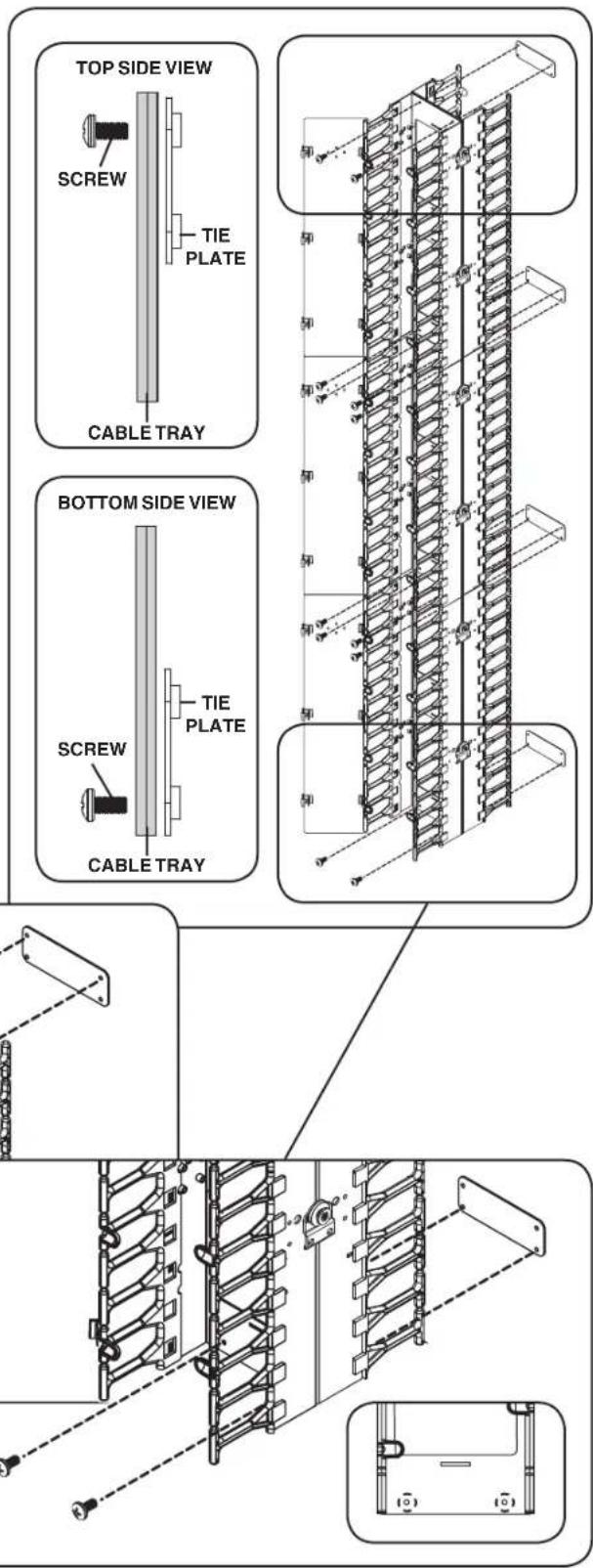
Technical line drawing of an electrical enclosure with multiple panels and mounting brackets (no text or symbols)Step 6 Repeat Steps 1-5 to assemble and mount the other four cable trays, then use (4) tie plates and (12) M4 x 8 mm screws to connect adjacent cable trays vertically and horizontally for added stability.
- Use (1) tie plate and (4) M4 x 8 mm screws to connect the bottom cable trays to the middle cable trays. This will also connect the cable trays back-to-back.
- Use (1) tie plate and (4) M4 x 8 mm screws to connect the top cable trays to the middle cable trays. This will also connect the cable trays back-to-back.

natural_image
Technical line drawing of a mechanical assembly with no visible text or symbols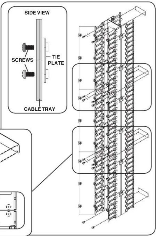
Double-Depth Installation (SRCABLEVRT6 & SRCABLEVRT12 only)
Step 6 continued
- Use (1) tie plate and (2) M4 x 8 mm screws to connect the top cable trays back-to-back.
- Use (1) tie plate and (2) M4 x 8 mm screws to connect the bottom cable trays back-to-back.
Note: Insert the screws on the opposite side of the cable tray surface from the tie plate, as shown in the diagrams. Make sure the flat side of the tie plate faces the cable tray surface so the screws will thread into the tie plate properly.
Double-Depth Installation (SRCABLEVRT6 & SRCABLEVRT12 only)
Step 7 (Optional) Repeat Steps 1-6 to install additional cable trays on the other side of the rack. (A double-depth installation on both sides of the rack requires 4 x SRCABLEVRT6 or SRCABLEVRT12.)

Note: SRCABLEVRT6 is shown. The cable tray frames and doors of the SRCABLEVRT12 are wider, but installation is identical.
SR42UBWD Installation: Front-Facing (SRCABLEVRT3 only)
Step 1 Using (2) M4 x 6 mm flat head screws, attach (2) mounting brackets to the rear side of (1) cable tray frame.
Note: The mounting brackets should be aligned so that the three mounting holes form a horizontal line. Depending on which side of the enclosure you choose to install the SRCABLEVRT3, the round end of the mounting bracket should be closest to the exterior of the enclosure.

natural_image
Technical line drawing of a multi-tiered server rack with mounting brackets and connectors (no text or symbols)Step 2 Using (2) M4 x 12 mm pan head screws, attach (2) mounting buttons to the mounting brackets.

SR42UBWD Installation: Front-Facing (SRCABLEVRT3 only)
Step 3 Attach (4) cable guides to the cable tray frame. The cable guides slide over the edges of the cable tray frame to form a tight attachment.

flowchart
graph TD
    A["Server Rack"] --> B["Data Bus"]
    B --> C["Device Component"]
    C --> D["Storage System"]
    D --> E["Output Server"]
    style A fill:#f9f,stroke:#333
    style E fill:#bbf,stroke:#333
Step 4 Slide (6) door hinges over the edges of (3) cable tray door straps, then fasten the door straps to the cable guides via the door hinges' C clasps. After installation, you can release the C clasps on one side of the cable tray door straps to open them from either side.

flowchart
graph TD
    A["Assembly"] --> B["Storage"]
    B --> C["Processing"]
    C --> D["Final Output"]

    subgraph Stage1
    A --> E["Assembly"]
    E --> F["Storage"]
    F --> G["Processing"]
    G --> H["Final Output"]

    subgraph Stage2
    A --> I["Assembly"]
    I --> J["Storage"]
    J --> K["Processing"]
    K --> L["Final Output"]

    style A fill:#f9f,stroke:#333
    style B fill:#f9f,stroke:#333
    style C fill:#f9f,stroke:#333
    style D fill:#f9f,stroke:#333
    style E fill:#ccf,stroke:#333
    style F fill:#ccf,stroke:#333
    style G fill:#ccf,stroke:#333
    style H fill:#ccf,stroke:#333
    style I fill:#ccf,stroke:#333
    style J fill:#ccf,stroke:#333
    style K fill:#ccf,stroke:#333
    style L fill:#ccf,stroke:#333
SR42UBWD Installation: Front-Facing (SRCABLEVRT3 only)
Step 5 Align the mounting buttons with the toolless mounting slots on one of the rails on either side of the front of the rack, so that the SRCABLEVRT3 is facing the front door. Insert the mounting buttons through the slots and slide the cable tray downward until secure. Use (2) M4 x 12 mm pan head screws inside of the rack rail to fasten the cable tray in place.
Note: Always begin installation at the bottom of the rack and work your way to the top.
Step 6 Repeat steps 1-5 to assemble and mount the other two cable trays.

natural_image
Technical line drawing of a server rack with mounting holes and internal components (no text or symbols)SR42UBWD Installation: Side-Facing (SRCABLEVRT3 only)
Step 1 Using (2) M4 x 6 mm flat head screws, attach (2) mounting brackets to either side of (1) cable tray frame.
Note: The mounting brackets should be aligned so that the three mounting holes form a vertical line, with the round end of the bracket at the top.

natural_image
Technical line drawing of a multi-tiered server rack with mounting bracket (no text or symbols)Step 2 Using (2) M4 x 12 mm pan head screws, attach (2) mounting buttons to the mounting brackets.
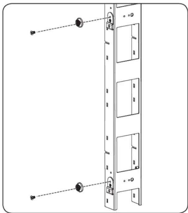
natural_image
Technical line drawing of a multi-panel server rack with mounting holes and dashed lines indicating alignment (no text or symbols)SR42UBWD Installation: Side-Facing (SRCABLEVRT3 only)
Step 3 Attach (4) cable guides to the cable tray frame. The cable guides slide over the edges of the cable tray frame to form a tight attachment.

flowchart
graph TD
    A["Top Block"] --> B["Intermediate Block"]
    B --> C["Bottom Block"]
    style A fill:#f9f,stroke:#333
    style B fill:#bbf,stroke:#333
    style C fill:#dfd,stroke:#333
Step 4 Slide (6) door hinges over the edges of (3) cable tray door straps, then fasten the door straps to the cable guides via the door hinges' C clasps. After installation, you can release the C clasps on one side of the cable tray door straps to open them from either side.

flowchart
graph TD
    A["Step 1: Initial Box"] --> B["Step 2: Box with Arrow"]
    B --> C["Step 3: Box with Arrow"]
    C --> D["Step 4: Box with Arrow"]

natural_image
Diagram of a multi-tiered rack-mounted device with directional arrows indicating assembly or movement (no text or symbols present)SR42UBWD Installation: Side-Facing (SRCABLEVRT3 only)
Step 5 Align the mounting buttons with the toolless mounting slots on one of the rails on either side of the front of the rack, so that the SRCABLEVRT3 is facing the center of the rack. Insert the mounting buttons through the slots and slide the cable tray downward until secure. Use (2) M4 x 12 mm pan head screws inside of the rack rail to fasten the cable tray in place.
Note: Always begin installation at the bottom of the rack and work your way to the top.
Step 6 Repeat steps 1-5 to assemble and mount the other two cable trays.

natural_image
Technical line drawing of a server rack cabinet with mounting hardware (no text or symbols)42U Enclosure with PDU Manager Installation Side-Facing (SRCABLEVRT3 only)
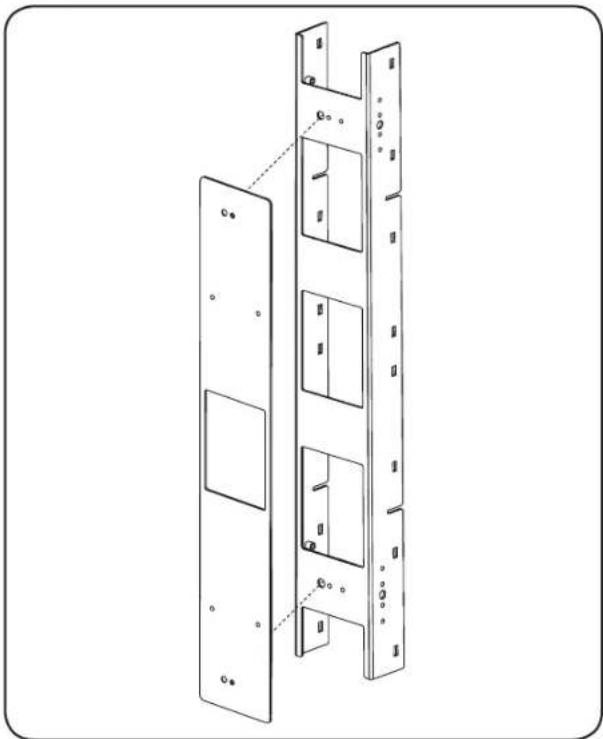
Step 1 Attach the cable tray frame to the adapter plate using (2) M4 x 8 mm screws.
natural_image
Technical line drawing of a multi-panel door frame structure (no text or symbols)42U Enclosure with PDU Manager Installation Side-Facing (SRCABLEVRT3 only)
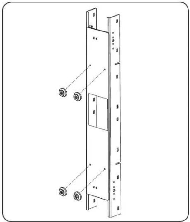
Step 2 Using (4) M4 x 12 mm pan head screws, attach the mounting buttons to the back of the adapter plate frame.
natural_image
Technical line drawing of a multi-panel refrigerator with mounting holes and a door (no text or symbols)Step 3 Attach the (4) cable guides to the cable tray frame. The cable guides slide over the edges of the cable tray frame to form a tight attachment.
flowchart
graph TD
    A["Server Rack"] --> B["Network Routing"]
    B --> C["Device Array"]
    C --> D["Server Rack"]
    D --> E["Network Routing"]
    E --> F["Device Array"]
    style A fill:#f9f,stroke:#333
    style D fill:#bbf,stroke:#333
    style E fill:#bfb,stroke:#333
42U Enclosure with PDU Manager Installation Side-Facing (SRCABLEVRT3 only)
Step 4 Slide (6) door hinges over the edges of (3) cable tray door straps, then fasten the door straps to the cable guides via the door hinges' C clasps. After installation, you can release the C clasps on one side of the cable tray door straps to open them from either side.

flowchart
graph TD
    A["Top Product"] --> B["Step 1"]
    B --> C["Step 2"]
    C --> D["Step 3"]
    D --> E["Bottom Product"]

natural_image
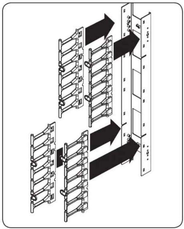
Diagram of a multi-layered server rack structure with directional arrows indicating assembly or data flow (no text or symbols present)Step 5 Align the mounting buttons with the toolless mounting slots on the enclosure's PDU manager, so that the SRCABLEVRT3 is facing the center of the rack. Insert the mounting buttons through the slots and slide the cable tray downward until secure.
Note: Always begin installation at the bottom of the rack and work your way to the top.

natural_image
Technical diagram of a server rack with multiple racks and connections, showing internal structure and mounting points (no text or labels)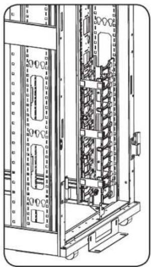
natural_image
Technical line drawing of an electrical cabinet with internal components and mounting brackets (no text or symbols)Step 6 Repeat steps 1-5 to assemble and mount the other two cable trays.
Warranty & Warranty Registration
5-Year Limited Warranty
Seller warrants this product, if used in accordance with all applicable instructions, to be free from original defects in material and workmanship for a period of 5 years from the date of initial purchase. If the product should prove defective in material or workmanship within that period, Seller will repair or replace the product, at its sole discretion.
THIS WARRANTY DOES NOT APPLY TO NORMAL WEAR OR TO DAMAGE RESULTING FROM ACCIDENT, MISUSE, ABUSE OR NEGLECT. SELLER MAKES NO EXPRESS WARRANTIES OTHER THAN THE WARRANTY EXPRESSLY SET FORTH HEREIN. EXCEPT TO THE EXTENT PROHIBITED BY APPLICABLE LAW, ALL IMPLIED WARRANTIES, INCLUDING ALL WARRANTIES OF MERCHANTABILITY OR FITNESS, ARE LIMITED IN DURATION TO THE WARRANTY PERIOD SET FORTH ABOVE; AND THIS WARRANTY EXPRESSLY EXCLUDES ALL INCIDENTAL AND CONSEQUENTIAL DAMAGES. (Some states do not allow limitations on how long an implied warranty lasts, and some states do not allow the exclusion or limitation of incidental or consequential damages, so the above limitations or exclusions may not apply to you. This warranty gives you specific legal rights, and you may have other rights which vary from jurisdiction to jurisdiction).
WARNING: The individual user should take care to determine prior to use whether this device is suitable, adequate or safe for the use intended. Since individual applications are subject to great variation, the manufacturer makes no representation or warranty as to the suitability or fitness of these devices for any specific application.
Warranty Registration
Visit www.triplite.com/warranty today to register the warranty for your new Tripp Lite product.You'll be automatically entered into a drawing for a chance to win a FREE Tripp Lite product!*
* No purchase necessary. Void where prohibited. Some restrictions apply. See website for details.
Tripp Lite has a policy of continuous improvement. Specifications are subject to change without notice.

1111 W. 35th Street, Chicago, IL 60609 USA
www.tripplite.com/support
201202097·933029-EN
- Owner's Manual
- SmartRack™ High-Capacity Vertical Cable Manager
- Introduction
- Parts List
- Single-Depth Installation (SRCABLEVRT6 & SRCABLEVRT12 only)
- Double-Depth Installation (SRCABLEVRT6 & SRCABLEVRT12 only)
- Step 6 continued
- SR42UBWD Installation: Front-Facing (SRCABLEVRT3 only)
- SR42UBWD Installation: Side-Facing (SRCABLEVRT3 only)
- 42U Enclosure with PDU Manager Installation Side-Facing (SRCABLEVRT3 only)
- Warranty & Warranty Registration
- 5-Year Limited Warranty
- Warranty Registration
Brand : Tripp Lite
Model : SmartRack SRCABLEVRT3FC
Category : Computer and Peripheral Cables