EXT-DVI-241DL - Switch Gefen - Free user manual and instructions
Find the device manual for free EXT-DVI-241DL Gefen in PDF.

| Type | DVI Switch |
| Model | EXT-DVI-241DL |
| Brand | Gefen |
| Number of Inputs | 4 |
| Number of Outputs | 1 |
| Connector Type | DVI-D (Single Link) |
| Maximum Resolution | 1920x1200 @ 60Hz |
| Supported Audio | No (video only) |
| EDID Management | Yes |
| HDCP Compliance | Yes |
| Power Supply | 5V DC, 1A (included) |
| Dimensions (W x D x H) | 4.3 x 2.2 x 1.1 inches |
| Weight | 0.5 lbs |
| Housing Material | Metal |
| Switching Method | Push-button or IR remote (optional) |
| LED Indicators | Power and selected input |
| Operating Temperature | 32°F to 104°F (0°C to 40°C) |
| Certifications | FCC, CE |
| Maintenance | Wipe with dry soft cloth; avoid liquids |
| Safety | Use only included power adapter; keep away from water |
| Repairability | No user-serviceable parts; contact support |
Frequently Asked Questions - EXT-DVI-241DL Gefen
User questions about EXT-DVI-241DL Gefen
0 question about this device. Answer the ones you know or ask your own.
Ask a new question about this device
Download the instructions for your Switch in PDF format for free! Find your manual EXT-DVI-241DL - Gefen and take your electronic device back in hand. On this page are published all the documents necessary for the use of your device. EXT-DVI-241DL by Gefen.
USER MANUAL EXT-DVI-241DL Gefen
Technical Support Hours:
8:00 AM to 5:00 PM Monday thru Friday.
Write To:
Gefen LLC
c/o Customer Service
20600 Nordhoff St
Chatsworth, CA 91311
www.gefen.com
support@gefen.com
Notice
Gefen LLC reserves the right to make changes in the hard ware, packaging, and any accompanying doc u men ta tion without prior written notice.
2x1 DVIKVM DL Switch is a trademark of Gefen LLC
1 Intr oduction
2 Operation Notes
3 Features
4 Panel La yout
5 Panel Descriptions
6 IR RemoControl
6 Layout and Descriptions
7 Install the Battery
7 Setting the IR channel
8 Connecting the 2x1 DVIKVM DLSwitch
8 Wirin Diagram
9 Operating the 2x1 DVIKVM DLSwitch
9 Switching sources
9 Switching using the IR Remote Control
10 Switching using the RMT2
11 Switching using contact closure
12 Setting the IR channel
13 Using the IR Extender
14 Specifications
15 Warranty
Congratulations on your purchase of the Gefen 2X1 DVIKVM DL Switch. Your complete satisfaction is very important to us.
Gefen
Gefen delivers innovative, progressive computer and electronics add-on solutions that harness integration, extension, distribution and conversion technologies. Geten's reliable, plug-and-play products supplement cross-platform computer systems, professional audio/video environments and HDTV systems of all sizes with hard-working solutions that are easy to implement and simple to operate.
The Gefen 2X1 DVIKVM DL Switch
The 2X1 DVIKVM DL Switch allows effortless switching between two cross-platform dual link DVI computers using just one dual link DVI display and USB 2.0 keyboard and mouse. Audio, video and control signals are switched for each computer upon selection, providing an easy and effective method of accessing two computers from one workstation without the hassle of networking.
How It Works
Connect a dual link DVI display and USB 2.0 keyboard/mouse to the 2X1 DVIKVM DL Switch's outputs. Connect both computer's dual link DVI, USB and audio ports to the inputs on the Switcher using the supplied cables. From there, select the computer to control using the IR remote that comes with the Switcher. A contact closure remote control may also be used. The Switcher is compatible with both Macintosh and P C keyboards, mice and monitors.
PLEASE READ THESE NOTES BEFORE INSTALLING OR OPERATING THE 2X1 DVIKVM DL SWITCH
- When turning on or rebooting your computers, the DVI DL Switcher must be selected to the computer that is booting until the computer completes the boot cycle. This step can be eliminated using the Gefen DVI Detective, which stores the displays EDID.
- It you loose your picture when switch from source 1 to source 2 or vice-versa you will need a DVI Detective (Gefen part no. EXT-DVI-EDIDP).
- If you are experiencing USB dropouts try using the switcher just as a USB hub by only connecting the USB cables from your computers to the switcher. Connect your devices to the USB out portion of the switcher and connect your display to your computer directly. Start your computer up and try switching. If your USB devices do come up normally then you will need a DVI Detective to negotiate the video/USB signals for faster switching. If they do not come up normally, contact Gafen Technical Support for assistance.
Features
- Switches easily between any two DVI computers with USB 2.0 and audio
- Maintains highest resolution single link video
- Saves time and increase your productivity
- Use either PC or Mac USB 2.0 keyboard/mouse
- Independent EQ adjustments that compensate
- Front panel switching
• Parallel remote port (RMT-2 not included)
• Supports resolutions up to 1080p, 2K, and 1920 x 1200 (Single-Link)
• Supports DDWG standards for DVI monitors
Includes:
(1) 2X1 DVIKVM DLSwitch
(2) 6tt. Dual Link DVI cables
(2) 6ft. US B cables
(2) 3.5mm mini-stereo audio cables
(1) IR RemoteControl unit
(1) 5V DC Power Supply
(1) Quick Start Guide

text_image
Gefen 2x1 DVIKVM DL Switch Dual Link DVI•USB•Audio Switch Front Power IR Select Back 6 7 8 10 12 EXT:DVIKVM-241DL Gefen Audio 1 Audio 2 Audio Out Remote 5V DC DVI In 1 DVI Out DVI In 2 USB Out In 1 In 2 9 111 Power
This LED will glow bright red once the included 5V DC locking power supply has been connected and plugged into an available electrical outlet.
2 IR Sensor
Receives IR commands from the included IR Remote Control Unit.
3 Source Selection Indicators
These LED indicators will glow bright blue depending upon which input source is selected. Use the Select button to select the input source.
4 Select
Press this button to toggle between DVI In 1/USB In 1 and DVI In 2 / USB In 2.
5 5V CD
Connect the included 5V DC power supply to this connector.
6 Audio In 1 /Audio In 2
Connect the included 3.5mm mini-stereo cables from each computer / audio source to each of these 3.5mm mini-stereo jacks.
7 DVI Ou
Connect a DVI cable from the extender to an HDTV display.
8 Audio ①u
Connect a 3.5mm mini-stereo cable from this jack to the audio/video output device.
9 DVI In 1 / DVI In 2
Connect the included DVI cables from each computer source to each of these DVI connectors.
10 Remote
Used for contact-closure control. See page ## for details.
11 USB Ou
Connect up to two USB device to these USB ports. Both of these USB ports are active, depending upon the USB inputs.
12 USB In 1 / USB In 2
Connect the included USB cables from each computer source to these USB ports.
Layout and Descriptions
text_image
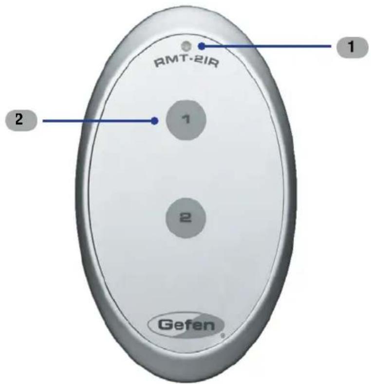
RMT-2IR 1 2 1 2 Gefen1 LED Indicato
This LED will be activated momentarily each time one of the two buttons are pressed.
2 Input Selection
Press these buttons to select the input source.

NOTE: An Activity Indicator that flashes quickly while holding down any one of the 16 buttons indicates a low battery. Replace the IR Remote Control battery as soon as possible.
Installing the Battery
The Remote Control unit ships with two batteries. One battery is required for operation and the other battery is a spare.
-
Remove the battery cover on the back of the IR Remote Control unit.
-
Insert the included battery y into the open battery slot. The positive (+) side of the battery should be facing up.
-
Replace the battery cover

text_image
Replace the battery cover Gefan www.gefin.com Battery slot DIP switches Channel 0 (def ault): Remote Channel 1: ON 1 2 ON 1 2 Remote Channel 2: Remote Channel 3: ON 1 2 ON 1 2Setting the IR Channel
The IR channel on the IR Remote Control must match the IR channel used by the 2x1 DVIKVM Switch. For example, if both DIP switches on the IR Remote Control unit are set to IR channel 0 (both DIP switches down), then the 2x1 DVIKVM DL Switch must also be set to IR channel 0. See page 12 for information on how to charge the IR channel on the 2x1 DVIKVM DL Switch.

WARNING: Risk 0 explosion if battery is replaced by an incorrect type. Dispose of used batteries according to the instructions.
How to Connect the 2X1 DVIKVM DL Switch
- Connect the included dual-link DVI cables between the DVI outputs of each computer to the DVI input connectors on the 2X1 DVIKVM DL Switch.
- Connect the included USB cables from each computer to the USB In ports on the 2X1 DVIKVM DL Switch.
- Connect the included 3.5mm mini-stereo cables from each computer / audio source to the 3.5mm mini-stereo jacks on the 2X1 DVIKVM DL Switch.
- Connect the DVI output on the 2X1 DVIKVM DL Switch to an HDTV display using a DVI cable.
- Connect a 3.5mm mini-stereo cable from the 2X1 DVIKVM DL Switch to the audio/video device or a set of powered speakers.
- Connect the included 5V DC power supply to the 2X1 DVIKVM DL Switch. Plug the AC power cords from the power supply to an available electrical outlet.
Wiring Diagram for the 2X1 DVIKVM DL Switch

flowchart
graph TD
    A["Computer"] -->|DVI KVM Switcher| B["Computer"]
    B -->|DVI (SL/DL) CABLE| C["USB CABLE"]
    B -->|MINI STEREO AUDIO CABLE| D["Computer"]
    D -->|Display w/USB & Audio| E["Computer"]
    F["Powered Speakers"] --> B
    G["Gefen"] logo is displayed on the left. Note: External labels are not explicitly provided in the diagram; actual system diagram shows connections between computer, DVI KVM Switcher, and external devices. Text 'EXT-DVIKVM-241DL' appears at bottom right. Legend indicates green for DVI (SL/DL) CABLE, green for MINI STEREO AUDIO CABLE, gray for USB CABLE. Node labels appear in parentheses below the diagram. Source: EXT-DVIKVM-241DL.
Switching sources
Use the Select button on the front panel or the included IR Remote Control unit to switch between sources.
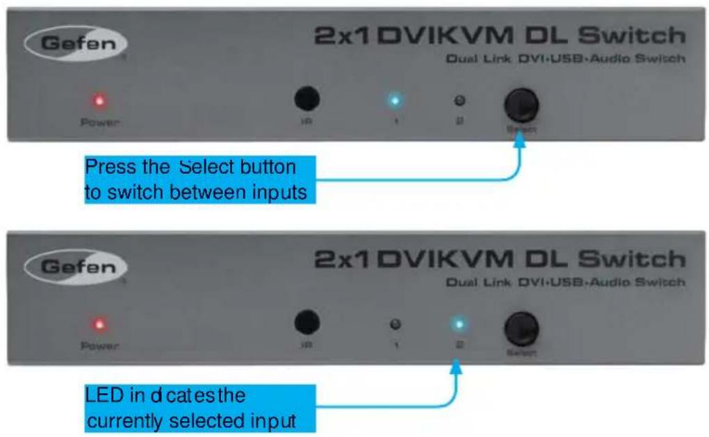
Switching using the front panel
- Press tSelect button on the front panel to toggle between input 1 (DVI In 1) and input 2 (DVI In 2).
text_image
Gefen 2x1 DVIKVM DL Switch Dual Link DVI-USB-Audio Switch Power IP 1 2 Select Press the Select button to switch between inputs Gefen 2x1 DVIKVM DL Switch Dual Link DVI-USB-Audio Switch Power IP 1 2 Select LED in d catesthe currently selected inputSwitching using the IR Remote Control
- Select the desired input by pressing the associated button on the IR Remote Control unit, as shown below

text_image
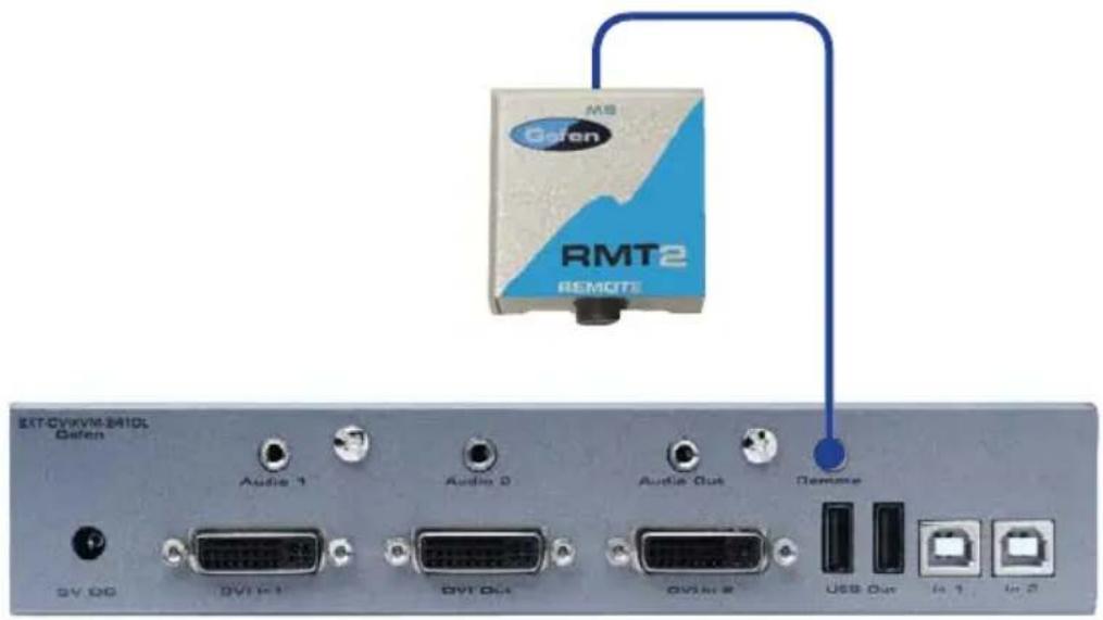
RMT-2IR 1 2 Gefen LED indicates a button was pressed 2x1 DVIKVM DL Switch Dual Link DVI-USB-Audio Switch IR 1 0 SelectSwitching using the RMT2 (not included)
- Connect the RMT2 Remote (Gefen part no. EXT-RMT-2) to the Remote jack on the 2X1 DVIKVM DL Switch, using a 3.5mm mini-stereo cable.
text_image
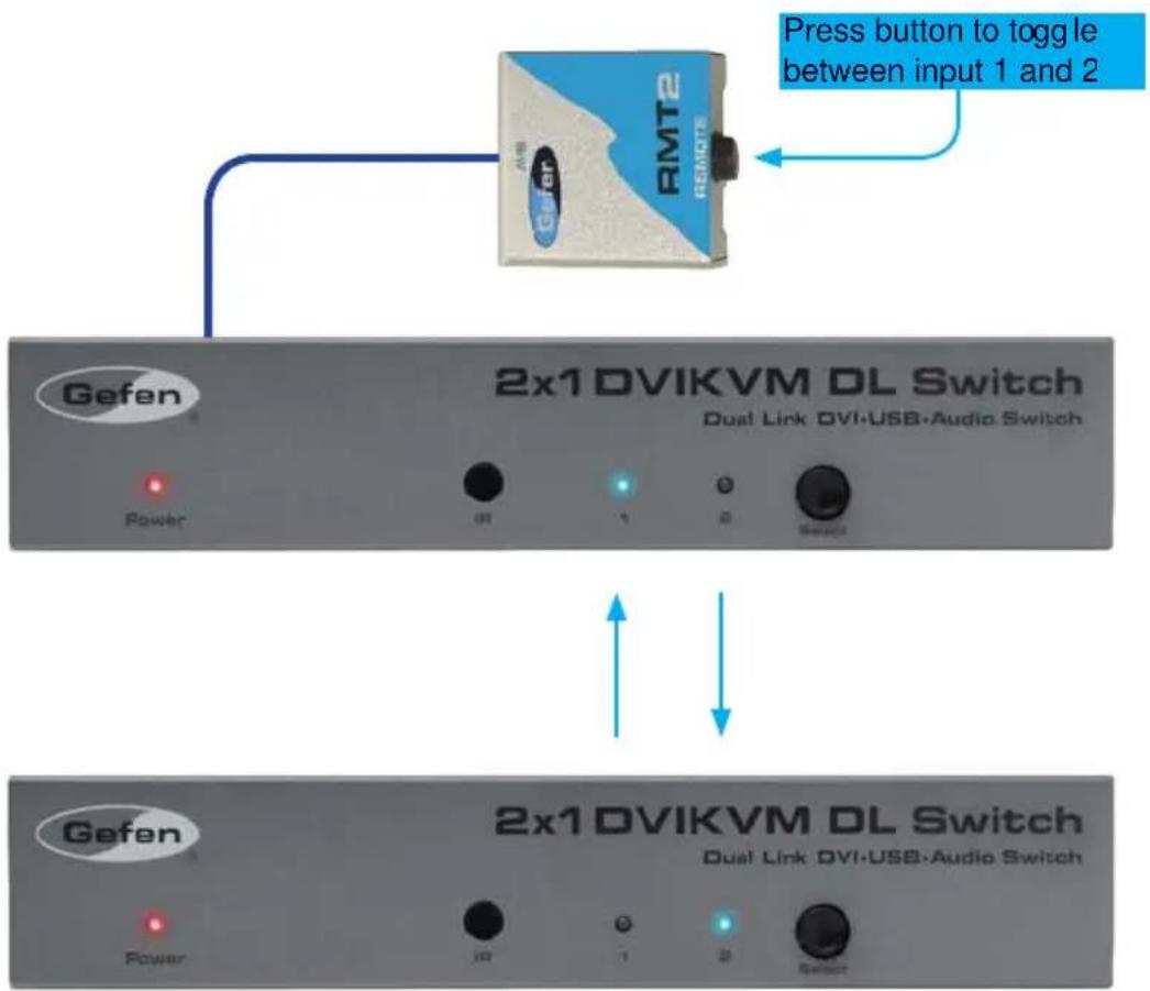
EXT-CVIXVM-B410L Dafen Audio 1 Audio 2 Audio Out Remote GV DG DV1 F1 DV1 Out DV1M E USB Out In 1 In 2- Press the button on the front of the RMT2 Remote to switch between DVI In 1 and DVI In 2.
text_image
Press button to toggle between input 1 and 2 Gefen 2x1 DVIKVM DL Switch Dual Link DVI•USB•Audio Switch Power 0T 1 2 Select Gefen 2x1 DVIKVM DL Switch Dual Link DVI•USB•Audio Switch Power 0T 1 2 SelectSwitching using Contact Closure
- Locate the DIP switch bank on the bottom of the 2x1 DVIKVM Switch.

text_image
Diagram of an electronic device rear panel showing connector pinout and terminal labels in Chinese- Set DIP switch 3 to the ON position to enable discrete contact closure switching.

text_image
UN SAB 1 2 3 4 5 6 7 8 Set DIP 3 to the ON position
NOTE: When DIP switch 3 is set to the ON position, then the 2x1 DVIKVM DL Switch will no longer receive IR commands from the IR Remote Control unit. Set DIP switch 3 to the OFF position to re-enable IR control.
When discrete contact closure switching is enabled, the following actions are valid:
• It the remote wire is note shorted, then DVI In 1 will always be selected.
• If the ring is shorted to the sleeve, then DVI In 2 will always be selected.
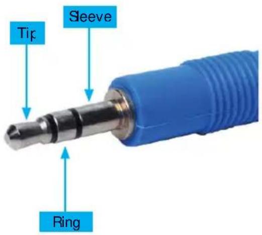
The diagram below outlines a typical 3.5mm mini-stereo TRS (Tip-Ring-Sleeve) connector.
| Termination | Phase |
| Tip | Positive (+) |
| Hing | Negative (-) |
| Sleeve | Signal ground |
text_image
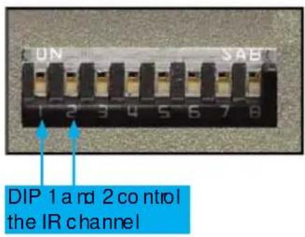
Tip Sleeve RingSetting the IR channel on the 2x1 DVIKVM DL Switch
The IR channel on the 2x1 DVIKVM DL Switch must match the IR channel used by the IR Remote Control unit. Use DIP switch 1 and DIP switch 2 to set the appropriate IR channel on the 2x1 DVIKVM DL Switch. Refer to page 7 for information on setting the IR channel on the IR Remote Control unit.
text_image
CUN SAE 1 2 3 4 5 6 7 8 DIP 1 and 2 control the IR channelChannel 0 (déault): Remote Channel 1:


Remote Channel 2 Remote Channel 3:


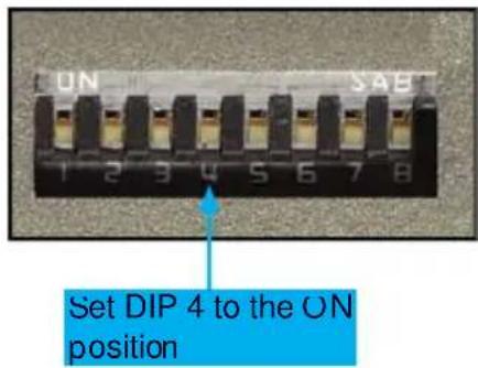
Using the IR Extender (not included)
- On the bottom of the 2x1 DVIKVM DL Switch, locate the DIP switch bank and set DIP switch 4 to the ON position.
text_image
UN SAB 1 2 3 4 5 6 7 8 Set DIP 4 to the ON position- Connect the IR Extender to the Remote Jack on the 2x1 DVIKVM DL Switch.
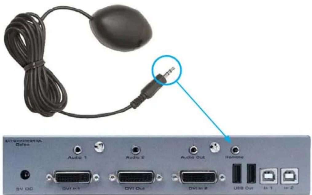
text_image
Extravimational Defense Audio 1 Audio 2 Audio Out Remove SV DC DVI In 1 DVI Out DVI In 2 USB Out In 3 In 4- Point the IR Remote Control unit at the IR Extender to control the 2x7 DVIKVM DL Switch.
Maximum Pixel Clock.... 165 MHz
Video Input Connectors.... (2) DVI-I 29 pin, female (digital only)
Video Output Connector....(1) DVI-I 29 pin, female (digital only)
Audio Input Connectors.... (2) 3.5 mm mini-stereo jack
Audio Output Connector....(1) 3.5 mm mini-stereo jack
USB Host Connectors.... (2) USB Type B, female
USB Device Connectors.... (2) USB Type A, female
IR Remote Connector....(1) 3.5mm mini-stereo jack
Power Supply.... 5V DC
Power Consumption....10W (max.)
Dimensions (W x H x D).... 7.18" x 1.18" x 2.55"
(182mm × 30mm × 65mm)
Shipping Weight.... 3 lbs. (1.4 kg)
Gefen warrants the equipment it manufactures to be free from defects in material and workmanship.
If equipment fails because of such defects and Gefen is notified within two (2) years from the date of shipment, Gefen will, at its option, repair or replace the equipment, provided that the equipment has not been subjected to mechanical, electrical, or other abuse or modifications. Equipment that fails under conditions other than those covered will be repaired at the current price of parts and labor in effect at the time of repair. Such repairs are warranted for ninety (90) days from the day of reshipment to the Buyer.
This warranty is in lieu of all other warranties expressed or implied, including without limitation, any implied warranty or merchantability or fitness for any particular purpose, all of which are expressly disclaimed.
- Proof of sale may be required in order to claim warranty.
- Customers outside the US are responsible for shipping charges to and from Cefen.
- Copper cables are limited to a 30 day warranty and cables must be in their original condition.
The information in this manual has been carefully checked and is believed to be accurate. However, Geten assumes no responsibility for any inaccuracies that may be contained in this manual. In no event will Gefen be liable for direct, indirect, special, incidental, or consequential damages resulting from any defect or omission in this manual, even if advised of the possibility of such damages. The technical information contained herein regarding the features and specifications is subject to change without notice.
For the latest warranty coverage information, refer to the Warranty and Return Policy under the Support section of the Gefen Web site at www.gefen.com.
PRODUCT REGISTRATION
Please register your product online by visiting the Register Product page under the Support section of the Gefen Web site.

text_image
* M A - D V I K V M - 2 4 1 D L *Rev A4
20600 Nordhoff St., Chatsworth CA 91311 1-800-545-6900 818-772-9100 fax: 818-772-9120 www.gefen.com support@gefen.com