FLTW-7626 - Rear Camera Brandmotion - Free user manual and instructions
Find the device manual for free FLTW-7626 Brandmotion in PDF.


| Product Type | Rear View Camera (Replacement Cargo Lamp) |
| Brand | Brandmotion |
| Model | FLTW-7626 |
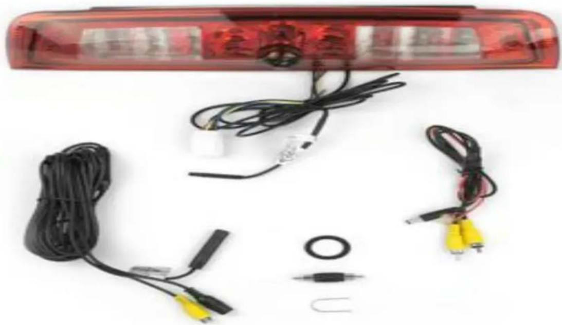
| Kit Contents | Camera lamp, chassis harness, power/video harness, adjustment tool, male-to-male RCA cable, installation instructions |
| Power Input | 12V DC (from vehicle ignition) |
| Camera Options | Grid lines on/off (connect green wires), mirror/non-mirror image (connect white wires) |
| Viewing Angle | Approx. 120° |
| Video Output | RCA composite video |
| Installation Complexity | Moderate - requires wiring and vehicle disassembly |
| Tools Required | Wire strippers, wire cutters, electrical tape, zip ties, plastic panel removal tools, multimeter, screwdriver, socket set, Torx bits |
| Camera Aim Adjustment | Yes, using supplied U-shaped tool |
| Material | Plastic housing with foam weather seal |
| Color | Black housing with red LED lens |
| Weight | Approx. 0.5 lb (0.23 kg) |
| Dimensions (approx.) | 4 x 2 x 2 inches (10 x 5 x 5 cm) |
| Safety Precautions | Work in ventilated area, secure vehicle, turn off ignition, wear safety goggles |
| Maintenance | Clean lens with soft cloth; check seals for leaks |
Frequently Asked Questions - FLTW-7626 Brandmotion
User questions about FLTW-7626 Brandmotion
0 question about this device. Answer the ones you know or ask your own.
Ask a new question about this device
Download the instructions for your Rear Camera in PDF format for free! Find your manual FLTW-7626 - Brandmotion and take your electronic device back in hand. On this page are published all the documents necessary for the use of your device. FLTW-7626 by Brandmotion.
USER MANUAL FLTW-7626 Brandmotion
Please read thoroughly before starting installation and check that kit contents are complete.
Items Included in the Kit: Tools & Su
Replacement cargo lamp w/camera
Chassis harness
Power/video harness
Adjustment tool
Male to male RCA
These instructions
pplies Needed:
Wire strippers
Wire cutters
Electrical tape
Zip ties
Plastic panel removal tools
Digital Volt Meter / BCM safe test light
Screwdriver
Socket set/wrench
Torx bits
Safety Precautions:
• Work in well ventilated area that is clear of obstructions.
- Secure vehicle with tire chucks in both front and rear of tires.
- Turn vehicle accessories OFF and ensure ignition key is in OFF position.
- Wear safety goggles and snug fitting clothes.
- Use tools only for their intended purpose and which are in good repair.
- Only perform this task if confidence, skill, and physical ability permit.
NOTE: We strive to provide accurate and up-to-date installation instructions. For the latest full color instructions, as well as an installation video, please visit www.brandmotion.com
natural_image
Red LED rear light fixture with black cables, connectors, and a small sensor module (no visible text or symbols)INSTALLATION INSTRUCTIONS
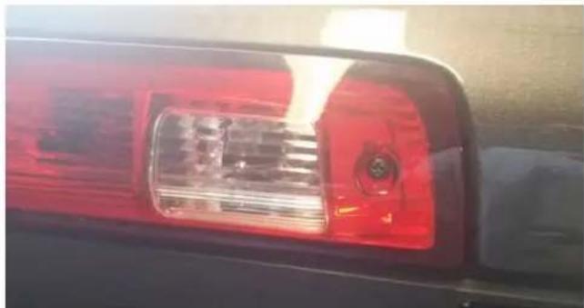
- Remove the factory cargo lamp from the vehicle by removing the (2) Phillips screws and lifting up from the bottom.
natural_image
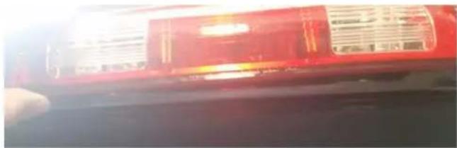
Close-up of a red-lit vehicle headlight with a circular emblem, mounted on a black vehicle (no visible text or symbols)- Unplug factory connector from the back of the light.
natural_image
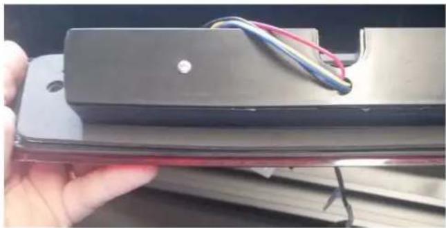
Close-up of a red vehicle rear light fixture with visible warning label (no readable text or symbols)- Attach the foam gasket to the new light by removing the backing of the foam tape and a line the screw holes of the light to the gasket.
natural_image
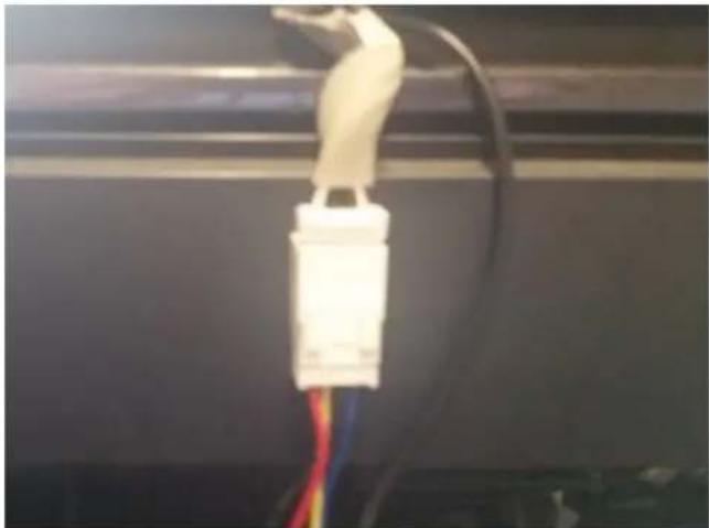
Hand holding a black electronic device with wires attached, no visible text or symbols- Plug the factory connector into the harness connector on the FLTW-7626.
natural_image
Close-up of a white electrical connector with wires, mounted on a black cable (no visible text or symbols)-
Insert the camera harness into the opening in the roof.
-
From the inside of the vehicle remove the rear of the headliner to gain access to the camera harness. (Each vehicle if different, be careful not to bend the headliner too much to access the harness).
-
Route the cable forward to the A-pillar of the vehicle.
-
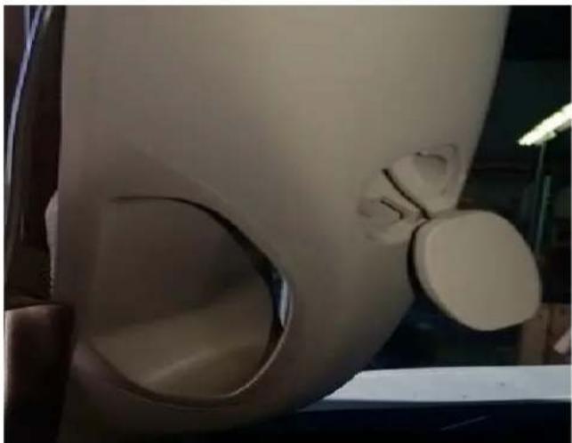
Remove the (2) covers on the handle to gain access to the 10mm bolts.
natural_image
Close-up of a white, curved mechanical component with a circular cutout, possibly part of a device or tool (no visible text or symbols)INSTALLATION INSTRUCTIONS
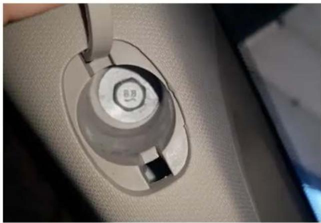
- Remove the (2) 10mm bolts and route the harness down the pillar toward the display. (Be careful of any airbags in the pillar and avoid routing the harness over the airbag).
natural_image
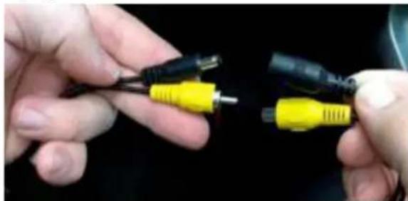
Close-up of a car interior showing a circular mechanical component with a small labeled part, being adjusted by a tool (no visible text or symbols)- Step 10: Connect Chassis Harness to supplied Power Harness RCA and power plugs.
natural_image
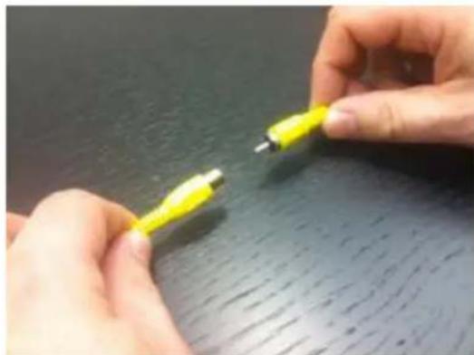
Close-up of hands holding two connected audio/video cables (no text or symbols visible)- Connect Power Harness male RCA connector to RCA located on your Display.
natural_image
Close-up of hands holding a yellow USB cable against a dark surface (no text or symbols visible)-
Using a vehicle specific service guide/wiring diagram and a multi-meter verify 12v Ignition. Red wire of power harness connects to 12v+ Ignition and Black wire of power harness to Black chassis ground nut or wire. RECOMMENDED: Solder wires and cover with Heat Shrink Tubing or use T-taps as an optional connection method.
-
Use Wire Ties or Electrical Tape to secure Chassis Harness and Jumper Harness RCA and power connections.
-
Coil any excess Chassis Harness and secure it to existing vehicle wiring with Wire Ties or Electrical Tape.
-
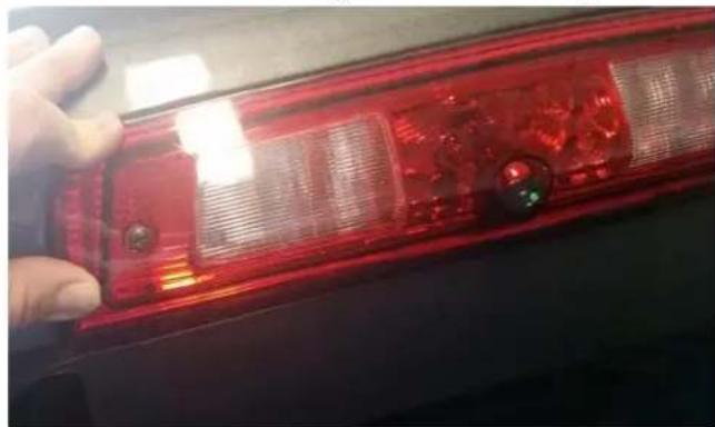
Install the new light with the factory screws.
natural_image
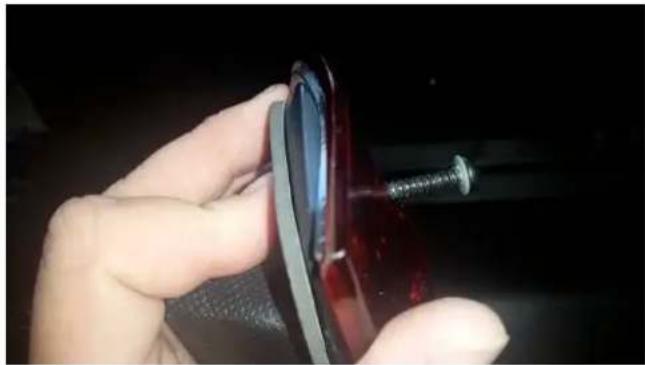
Close-up of a red LED light fixture with visible screw holes and surface texture (no text or symbols)- Start the screw in the light about a 14 inch and then put on back of vehicle cab and tighten the screws the rest of the way. (Be sure the foam gasket to set in the correct place). We are not responsible for leaks from around the new lamp.
INSTALLATION INSTRUCTIONS
natural_image
Close-up of a hand holding a red car tire with a screw, no visible text or symbols- Test system. Check display for the camera image.
(If necessary) Adjust camera aim.
Reposition camera to the desired viewing angle by using the U shape tool in kit, by inserting the ends into the "holes" around the lens.
- Reassemble vehicle. Follow your disassembly steps in reverse order, taking care not to bind the harness wiring when reinstalling trim.
CAMERA OPTIONS
The camera offers grid lines or non grid lines and mirror image or non mirror image options.
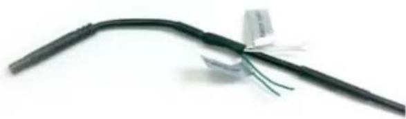
Grid line options: Default setting displays grid lines. To remove the grid line display, connect the two green wires near the end of the Camera Harness.
Display options: Default setting is mirror image display (i.e., words and letters appear backwards as in a mirror) for rearward facing camera (rear view) installation. To change to non mirror image display for forward facing camera (front view) connect the two
white wires near the end of the Camera Harness.
natural_image
Close-up of a black cable with attached wires, no visible text or symbolsGreen and White wires on the Camera Harness.
Brand : Brandmotion
Model : FLTW-7626
Category : Rear Camera