9002-8817 - Rear Camera Brandmotion - Free user manual and instructions
Find the device manual for free 9002-8817 Brandmotion in PDF.


| Product Type | Rear View Camera Kit |
| Brand | Brandmotion |
| Model | 9002-8817 |
| Compatibility | Jeep Wrangler 2007 – Current |
| Kit Includes | Camera, Chassis Harness, 15 Wire Ties, 3 Push Nuts, 22-pin White Connector with Video RCA, OBDII Flash Module |
| Camera Type | Rear vision camera with RCA video output |
| Power Requirement | 12V DC (ignition switched) |
| Connection Type | Wired with RCA video and 22-pin connector |
| Installation Difficulty | Moderate – requires trim removal, soldering recommended |
| Tools Required | T15 & T20 Torx bits, 7mm & 10mm sockets, Phillips screwdriver, plastic trim removal tool, soldering iron, electrical tape |
| Warranty Note | Warranty voided if camera harness is cut by running through bracket center |
| Programming | VIN-locked OBDII module; plug in until green LED, then remove |
| Display Activation | Automatic when vehicle shifted into reverse |
| Color | Black |
| Material | Plastic and metal components |
| Dimensions (Camera) | Approximately 1.5 inches in diameter |
| Weight (Kit) | Less than 1 lb |
| Mounting Location | Spare tire mount on rear gate |
Frequently Asked Questions - 9002-8817 Brandmotion
User questions about 9002-8817 Brandmotion
0 question about this device. Answer the ones you know or ask your own.
Ask a new question about this device
Download the instructions for your Rear Camera in PDF format for free! Find your manual 9002-8817 - Brandmotion and take your electronic device back in hand. On this page are published all the documents necessary for the use of your device. 9002-8817 by Brandmotion.
USER MANUAL 9002-8817 Brandmotion
INSTALLATION INSTRUCTIONS
Jeep Wrangler Rear Vision Camera Kit 2007 – Current (Kit # 9002-8817)
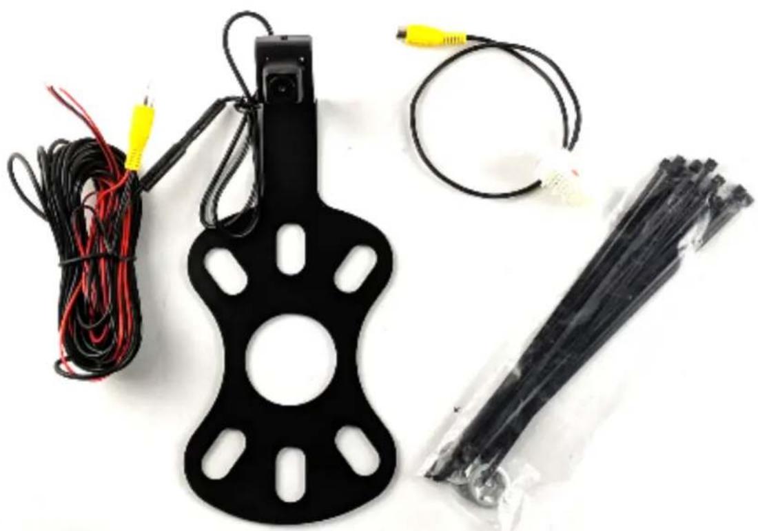
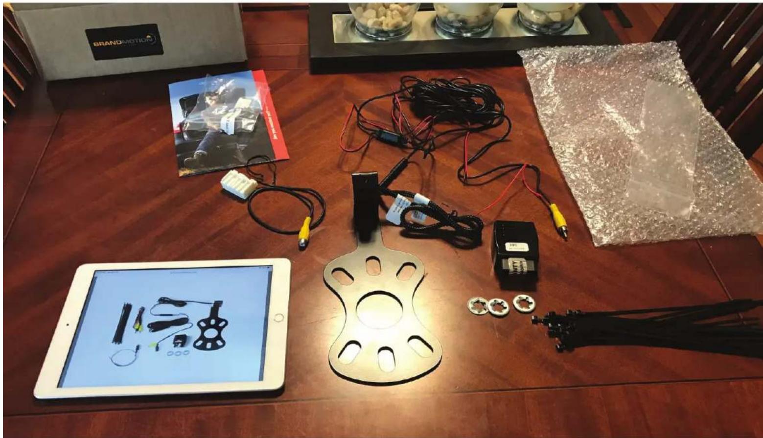
Items Included in the Kit
Camera
Chassis Harness
Zip lock bag with 15 Wire Ties & 3 Push Nuts
These Instructions
22--pin white connector w/ video RCA
OBDII Flash module
Required Tools & Supplies
T15 & T20 Torx Bits
7mm & 10mm Sockets
Phillips Screwdriver
Plastic Trim Removal Tool
Soldering Iron, Solder, & Heat Shrink Tubing
(RECOMMENDED) or T-taps as an alternate splicing method
Electrical Tape
natural_image
Black plastic electrical device with coiled wires and connectors, plus a bundle of black wires wrapped in plastic (no text or symbols visible)Please read so you do not VOID the warranty: If the camera harness is run through the center on the camera bracket, it will cut the camera harness. This will void the warranty on the camera.
INSTALLATION INSTRUCTIONS
Camera Power Instructions!: Only ONE of the red wires should be connected to ignition 12v+. The other should be isolated with electrical tape before powering camera up. See step 26.
Camera Installation
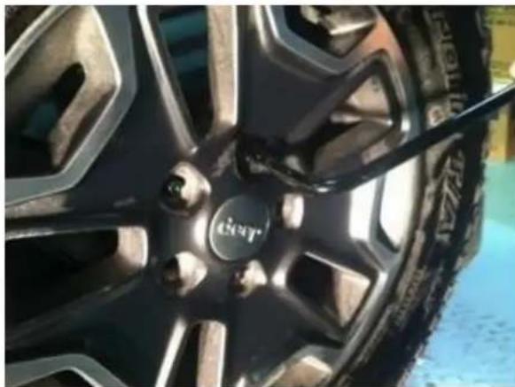
- Loosen lug nuts to remove the spare tire.
natural_image
Close-up of a car wheel rim with a brand mark and tire, no visible text or symbols- Slide Camera on studs placing harness end inside of tire carrier. Do not run harness through the camera bracket opening.
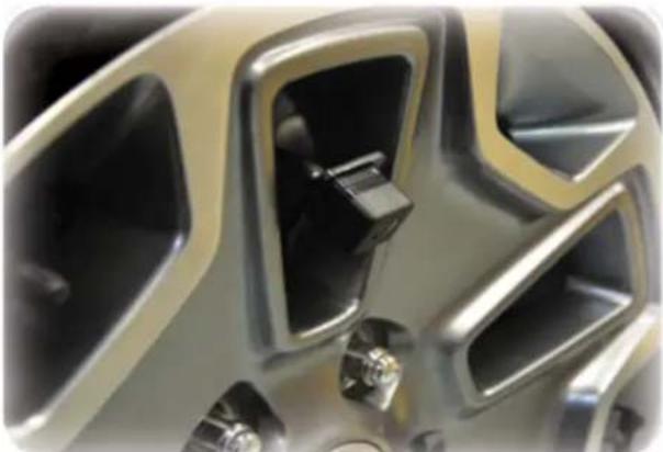
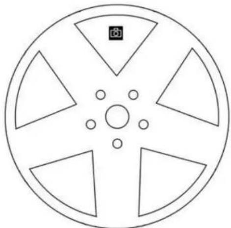
- Temporarily replace spare tire to check wheel clearance to Camera.
natural_image
Close-up of a metallic automotive component with hexagonal cutouts and mounting brackets (no visible text or symbols)Wheel Alignment for Camera Clearance
natural_image
Circular mechanical component with five blades and a central hub, featuring a camera icon (no text or symbols)- Remove spare tire and slide (3) supplied Push Nuts on the studs.
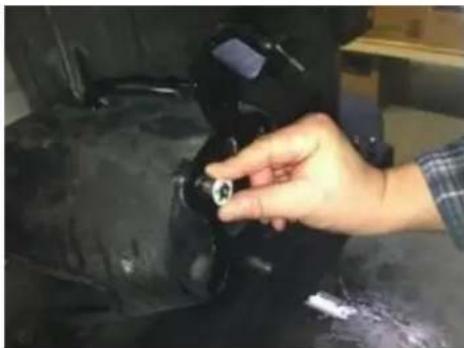
natural_image
Close-up of a hand adjusting a black mechanical component (no visible text or symbols)- Plug the Camera connector into the Chassis Harness connector, and insert RCA connector end of supplied Chassis Harness through the rear gate vent behind tire carrier.
INSTALLATION INSTRUCTIONS
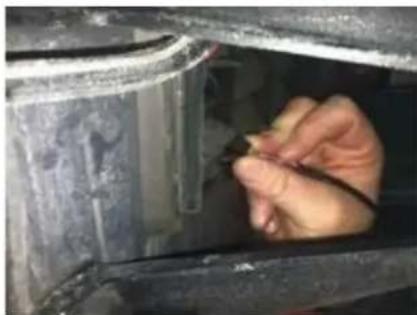
natural_image
Close-up of a hand inserting a small component into a metal enclosure (no visible text or symbols)- Using a plastic trim removal tool, remove interior panels on the inside of the rear gate.
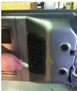
natural_image
Close-up of a hand inserting a small component into a sewing machine (no visible text or symbols)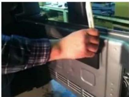
natural_image
Hand inserting a pen into a device inside a vehicle (no visible text or symbols)- Pull the harness through the rear gate openings
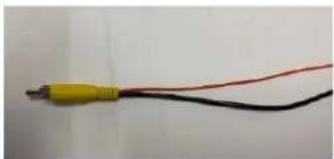
| RED wire at RCA | RED wire near Chassis Harness Connector | BLACK wire near Chassis Harness Connector |
| Blue/Red wire at power point | Ignition 12v+ | Chassis Ground |
natural_image
Close-up of a black and red electrical cable with a yellow connector (no text or symbols visible)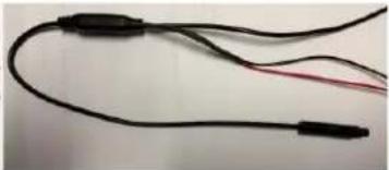
natural_image
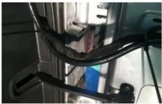
Close-up of black and red cables with connectors (no text or symbols visible)- Use supplied Wire Ties to secure Chassis Harness to existing harness.
natural_image
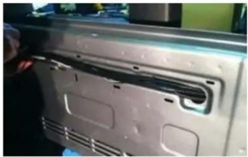
Close-up of a car door panel with visible black plastic components and ventilation slots (no text or symbols)- Use supplied Wire Ties to secure Chassis Harness to fabric factory wire cover. CAUTION: Leave enough slack to allow the gate to open fully.
natural_image
Close-up of black plastic cable connectors and wires in a mechanical or industrial setting (no visible text or symbols)- Use a T20 Torx bit to remove the subwoofer box. (If equipped)
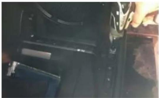
natural_image
Close-up of a mechanical component with black plastic parts and a hand adjusting a part (no visible text or symbols)- Using a plastic trim removal tool, pry off rear seat belt closeout.
INSTALLATION INSTRUCTIONS
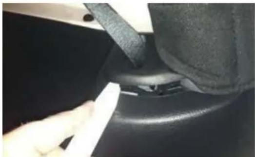
natural_image
Close-up of a hand pressing a black belt on a car seat (no visible text or symbols)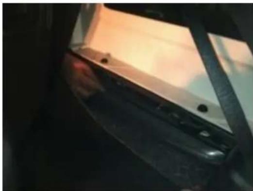
natural_image
Close-up of a dark mechanical component with a light beam and two small holes, possibly part of a device or fixture (no visible text or symbols)- Using a plastic trim removal tool, remove the rear access panel to expose 10mm bolt, and remove the bolt.
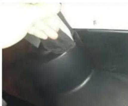
natural_image
Close-up of a hand applying adhesive to a dark, glossy surface (no text or symbols visible)-
Run Chassis Harness under B-pillar cover to passenger door sill. Use a plastic trim removal tool to remove the (2) plastic push pins and remove passenger sill plate/kick panel.
-
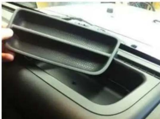
Remove rubber bin insert from top of the dash.
natural_image
Close-up of a car interior showing a hand holding a plastic tray with mesh grille (no text or symbols visible)-
Pull out subwoofer box slightly to gain access to run Chassis Harness along existing harness
-
Pull back the carpet and continue running Chassis Harness forward.
-
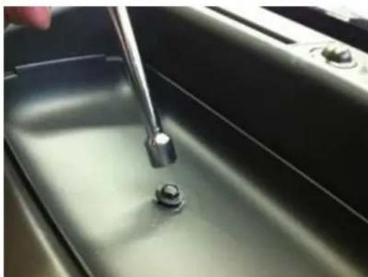
Remove 7mm bolt.
natural_image
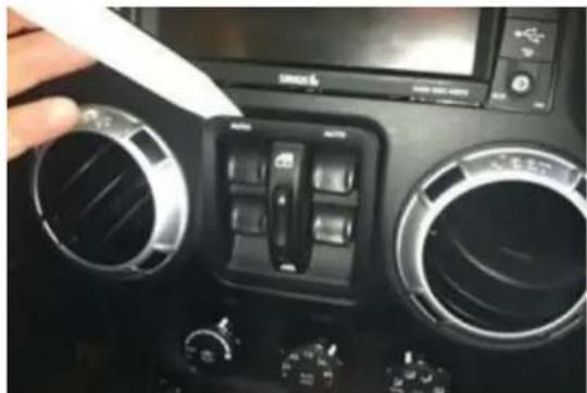
Close-up of a stainless steel kitchen sink with a hand using a wrench to press down the surface (no text or symbols visible)- Using a plastic trim removal tool, remove the window switch panel.
INSTALLATION INSTRUCTIONS
natural_image
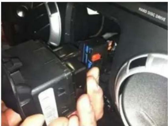
Close-up of a car air conditioning control panel with a hand inserting a white cable (no visible text or symbols)- Disconnect harness from window switches.
natural_image
Close-up of a hand inserting a device into a car's air vent, showing no visible text or symbols.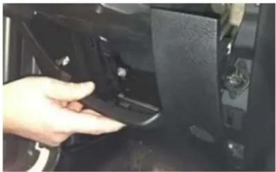
natural_image
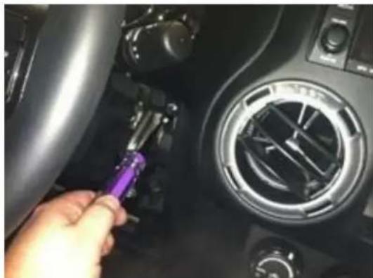
Hand placing a component into a black mechanical device (no visible text or symbols)- Remove (2) 7mm bolts on both sides of the steering column.
natural_image
Close-up of a hand using a purple tool to adjust the dashboard of a car intake manifold (no visible text or symbols)-
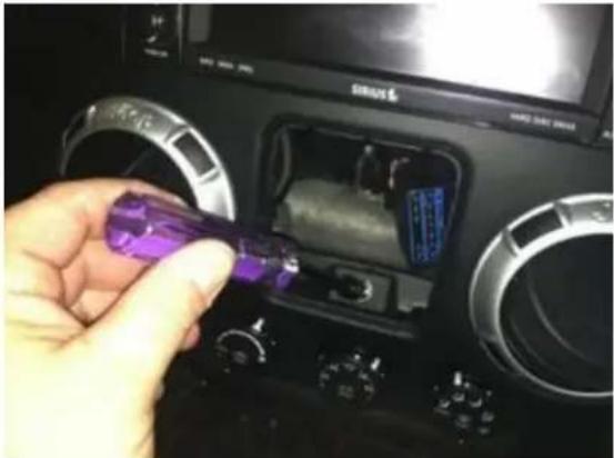
Remove center stack/cluster surround.
-
Remove 7mm bolt.
natural_image
Hand inserting a purple object into a car dashboard (no visible text or symbols)- Remove driver's knee bolster cover.
9002-8817 Instructions 09-17-2019 Page 5 of 7 DM
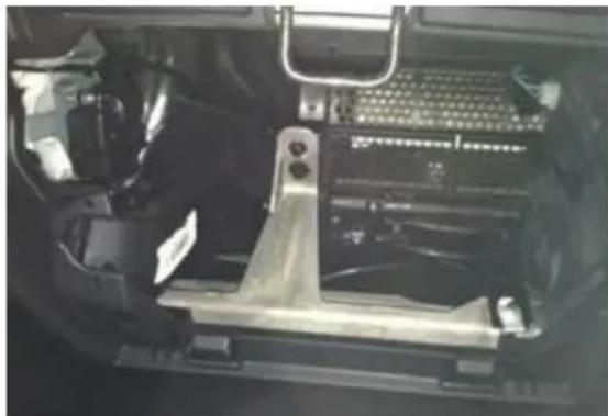
- Remove glove box for access and run Chassis Harness toward the center of the dash.
natural_image
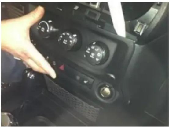
Interior view of a vehicle's dashboard frame with visible wiring and structural components (no text or symbols)- Using a plastic trim removal tool, remove HVAC panel.
INSTALLATION INSTRUCTIONS
natural_image
Close-up of a car dashboard with a hand interacting with the left side (no visible text or symbols)-
Connect all remaining radio connectors before reinstalling the radio head unit and all trim removed.
-
Connect male RCA of the camera into female RCA of jumper harness and proceed to the Dealer Programming Instructions.
26. Connecting Power
Splice Red power wire at the RCA to 12v+ wire at power point on center console OR splice red wire at chassis harness connector to 12v+ in the back of the vehicle. COVER UNUSED RED WIRE. Splice Black Ground to chassis ground. RECOMMENDED: Use solder and cover with heat shrink tubing or use T-taps as an alternate connection method.
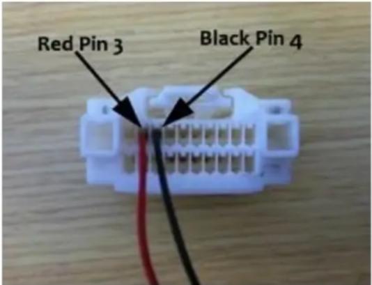
- Plug in the 22-pin white connector to the open connector on the back of the radio.
- Connect male RCA from chassis harness to the female RCA from 22-pin connector
Figure 1(For reference only)
Programming Instructions
PLEASE NOTE: These modules are VIN locked for single use.
1) Start the vehicle. Allow it to run for 20-30 seconds before proceeding to step 2.
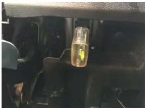
2) Plug module into OBDII port, located under the dash on the driver's side, and wait to see a GREEN LED on the module. Programming is completed.
3) Unplug the module from the OBDII port. DO NOT DISCARD.
INSTALLATION INSTRUCTIONS
natural_image
Close-up of a mechanical component with a yellow connector inserted, showing internal structure (no visible text or symbols)Test the system. Start vehicle and shift into Reverse to check that all connections were made properly. If all the connections are correct, you will see the camera image displayed on the factory display screen. To enable or disable the camera input, select from among rear vision options in radio settings.
natural_image
Top-down view of a tablet displaying an electronic device with various components including a laser, power cord, and wiring on a wooden surface (no visible text or symbols)- INSTALLATION INSTRUCTIONS
- Jeep Wrangler Rear Vision Camera Kit 2007 – Current (Kit # 9002-8817)
- Items Included in the Kit
- Required Tools & Supplies
- Please read so you do not VOID the warranty: If the camera harness is run through the center on the camera bracket, it will cut the camera harness. This will void the warranty on the camera.
- Camera Installation
- Connecting Power
- Programming Instructions
Brand : Brandmotion
Model : 9002-8817
Category : Rear Camera