SMR2016 - Video recorder Surveon - Free user manual and instructions
Find the device manual for free SMR2016 Surveon in PDF.

User questions about SMR2016 Surveon
0 question about this device. Answer the ones you know or ask your own.
Ask a new question about this device
Download the instructions for your Video recorder in PDF format for free! Find your manual SMR2016 - Surveon and take your electronic device back in hand. On this page are published all the documents necessary for the use of your device. SMR2016 by Surveon.
USER MANUAL SMR2016 Surveon
Smart Megapixel Video Recorder
Administrator Manual
Release 2.2
About This Document
This manual introduces the hardware components of SMR series and describes how to install them. It also provides an overview of Server surveillance functionality, and includes the functions of Video Management Software for operating and monitoring a Server network.
Version History
| Version | Description | Date |
| 1.0 | Initial release | November 2011 |
| 1.1 1. New models are added.2. Revise the Software Module Framework and add the System Architecture into the manual.3. Add instructions for the SCC.4. Add Software Installation section.5. Add instructions for the Web Client. | January 2012 | |
| 1.2 1. Add functionalities for SMR restore button.2. Update the VMS version to 2.4.7. | March 2012 | |
| 1.3 | New models are added. | May 2012 |
| 1.4 | Update for VMS2.4.7A09 | August 2012 |
| 1.5 | New models are added. | January 2013 |
| 1.6 | Update for VMS2.4.8 | May 2013 |
| 1.7 | New models are added. | June 2013 |
| 1.8 | Spec updated. | August 2013 |
| 1.9 | New VMS FW2.5AC 1.0 Added | August 2013 |
| 2.0 | UI Modified | November 2013 |
| 2.1 | Reinstallation section added | March 2014 |
| 2.2 | Remote Monitoring Modified | June 2014 |
All Rights Reserved © Surveon Technology 2014
Copyright Statement
No part of this publication may be reproduced, transmitted, transcribed, stored in a retrieval system, or translated into any language or computer language, in any form or by any means, electronic, mechanical, magnetic, optical, chemical, manual or otherwise, without the prior written consent of Surveon Technology Inc.
Disclaimer
Surveon Technology makes no representations or warranties with respect to the contents hereof and specifically disclaim any implied warranties of merchantability or fitness for any particular purpose. Furthermore, Surveon Technology reserves the right to revise this publication and to make changes from time to time in the content hereof without obligation to notify any person of such revisions or changes. Product specifications are also subject to change without notice.
Trademarks
Surveon and Surveon logo are trademarks of Surveon Technology Inc. Other names prefixed with “SMR” and “EMR” are trademarks of Surveon Technology Inc.
- Microsoft Windows and Windows are registered trademarks of Microsoft Corporation.
• Linux is a trademark of Linux Torvalds.
• Solaris and Java are trademarks of Sun Microsystems, Inc.
All other names, brands, products or services are trademarks or registered trademarks of their respective owners.
Table of Contents
About This Document 2
Version History 2
Copyright Statement 4
Table of Contents 5
Safety Precautions.... 19
Device Installation/Site Selection.... 20
Chapter 1. Product Overview....21
1.1. Features and Benefits.... 21
1.2. Specifications for the SMR Series 22
1.2.1. Hardware Specifications - Desktop Series 22
1.2.2. Hardware Specifications - Rackmount Series 23
1.2.3. VMS Specifications 24
Chapter 2. Hardware Overview ...... 26
2.1. Front Panel.... 26
2.2. Rear Panel 27
2.3. Hard Drive Designation.... 29
2.4. LED Definitions ...... 30
2.4.1. Desktop System Front Panel LEDs.... 30
2.4.2. Rackmount System Front LED Panel 31
2.4.3. Drive Tray LED 32
2.4.4. Rear Panel Ethernet LED 33
Chapter 3. Software Overview ...... 34
3.1. Software Introduction...... 34
3.2. Module Framework ...... 35
3.3. System Architecture.... 37
3.3.1. Standalone Server (Client-Server All-in-One) 38
3.3.2. Standalone Server + Remote Client (Web Client/ SPhone Client) ..... 39
3.3.3. Multiple Servers + SCC Client 42
3.3.4. Network Requirements.... 45
Opening Ports 45
Warnings / Precautions.... 45
3.4. Port Forwarding 46
3.4.1. Port Forwarding for Accessing VMS Server 47
Chapter 4. Installation ...... 50
4.1. Before You Start.... 50
4.1.1. Checklist for Operating Environment.... 50
4.1.2. Checklist for Network Topology.... 50
4.2. Hard Drive Installation .... 51
4.2.1. Hard Drive Installation Prerequisites.... 51
4.2.2. Inserting Hard Drive into Drive Tray (Desktop Series) 51
4.2.3. Inserting Hard Drive into Drive Tray (Rackmount Series) 53
4.3. System Connections ...... 55
4.4. Powering up SMR....57
4.4.1. SMR Desktop Systems 57
4.4.2. SMR Rackmount Systems 57
4.5. Install Wizard 58
4.6. Software Installation.... 65
4.6.1. Installing the VMS 65
4.7. Starting the VMS Client.... 70
4.7.1. Checking the Software Version.... 71
4.7.2. Logging out.... 71
Chapter 5. Reinstallation....72
5.1. Reset RAID....72
5.2. Reset the Whole System....75
Chapter 6. Basic System Settings ...... 82
6.1. Storage Management 82
6.2. Adding Cameras to the Server 84
6.2.1. Automatic Scan for Cameras 84
6.2.2. Manually Adding Cameras.... 88
6.3. Setting Recording Schedule 90
6.3.1. Weekly Scheduling 90
6.3.2. Daily Scheduling.... 92
6.4. Adding Alarm Rules 93
6.5. Setting up Live View....95
6.6. Using the LCD Menu in SMR Desktop Systems.... 96
6.6.1. Checking the System Status 96
6.6.2. Rebooting/ Shutting Down SMR 97
Chapter 7. Live View ...... 98
7.1. Live View Window Overview....98
7.1.1. Resizing and Minimizing Windows.... 100
Minimizing Controls 100
Hiding and Showing the Explorer Area....100
7.2.View Setup 101
7.2.1. Types of Views.... 101
7.2.2. Adding a View ...... 102
7.2.3. Add PAP View 104
7.2.4. Add Fisheye View 105
7.2.5. Renaming a View 106
7.2.6. Deleting a View.... 106
7.2.7. Sending View to a New Window.... 106
7.2.8. Switching Between Views 107
7.2.9. Switching Between Different Screen Divisions.... 107
Creating and Using New Screen Divisions.... 107
Screen Division Page Use....107
Auto-flipping Pages 108
Exiting Different Screen Divisions....108
7.3. Functionality Within Views.... 109
7.3.1. Digital Zoom 109
7.3.2. Instant Playback.... 110
7.3.3. Manual Recording 112
7.3.4. Preset Pan.... 113
7.3.5. Stream Selection 113
7.3.6. Image Settings.... 113
7.3.7. Video Ratio Adjustment 114
7.3.8. Inserting Overlays.... 114
Image Overlay 114
HTML Overlay 115
7.3.9. Send to Large Channel 115
7.3.10. Reconnect 116
7.3.11. Remove the Camera.... 116
7.3.12. Onscreen PTZ Control 117
Pan and Tilt 117
Zoom 117
7.4.Full Screen View 118
7.4.1. Entering Full Screen View.... 118
7.4.2. Exiting Full Screen Mode 118
7.5. E-Maps.... 119
7.5.1. Adding E-Maps 119
7.5.2. Adding Sub-Maps 119
7.5.3. Adding Additional E-Maps 120
7.5.4. Changing E-Map Order 121
7.5.5. Renaming an E-Map 121
7.5.6. Configuring an E-Map 121
7.5.7. Deleting an E-Map.... 122
7.5.8. Using the E-Map 122
Chapter 8. Server Setup ...... 124
8.1. Server Basic Functions.... 124
8.1.1. Logging into a Server 124
8.1.2. Logging out of a Server.... 124
8.1.3. Renaming a Server 125
8.1.4. Viewing Server and Client Information.... 125
8.2. Server Settings.... 126
8.2.1. General Server Settings 126
8.2.2. To perform Notification Setting.... 129
8.2.3. Pre/ Post Alarm Recording Settings 131
8.2.4. Storage Management 132
8.3. Scheduling Recording.... 135
8.3.1. Global Scheduling 135
Weekly Global Scheduling.... 135
Daily Global Scheduling 137
8.3.2. Individual Scheduling.... 139
Weekly Individual Scheduling.... 139
Daily Individual Scheduling 140
Chapter 9. Camera Setup.... 142
8.1. Adding Cameras 142
9.1.1. Automatic Scan for Cameras 142
9.1.2.Manually Adding Cameras....145
9.1.3. Deleting a Camera 146
9.1.4. Initializing a Camera.... 147
8.2. Camera General Settings.... 148
8.2.1. Logging into a Camera.... 148
8.2.2. Changing the Camera Model and Vendor 148
8.2.3. General Settings.... 150
8.2.4. OSD Settings 151
8.2.5. Privacy Mask Settings.... 152
8.3. Camera Image and Quality Settings.... 154
8.3.1. Camera Image Settings.... 154
8.3.2. Advanced Video Settings.... 155
8.4. PTZ Settings 156
8.4.1. PTZ Settings.... 156
8.4.2. PTZ Preset Settings 157
Adding a Preset 157
Deleting a Preset 158
8.4.3. PTZ Patrol Settings.... 158
8.5. PTZ Controls.... 160
8.5.1. Directional Pad 160
Pan and Tilt 160
Zoom 160
8.5.2. Functional Buttons.... 161
Speed 161
Home....161
Preset 161
Adding a Preset 161
Deleting a Preset 161
Patrol 162
Start Auto Pan 162
Focus 162
Chapter 10. Alarms and Events.... 163
10.1. Camera VI Detection Settings 164
10.1.1. General Motion Detection 164
Configuring and Editing Detection Windows.... 164
Testing Detection Windows....165
Deleting a Detection Window 165
Enabling or Disabling a Detection.... 165
Opening the Help File 165
10.1.2. Foreign Object Detection.... 166
Configuring and Editing Detection Windows.... 166
Testing Detection Windows.... 167
Deleting a Detection Window 167
Enabling or Disabling a Detection.... 167
Opening the Help File 168
10.1.3. Forbidden Area Detection 169
Configuring and Editing Detection Windows.... 169
Testing Detection Windows....170
Deleting a Detection Window 170
Enabling or Disabling a Detection.... 170
Opening the Help File 171
10.1.4. Intrusion Detection 172
Configuring and Editing Detection Windows.... 172
Testing Detection Windows.... 173
Deleting a Detection Window 173
Enabling or Disabling a Detection.... 173
Opening the Help File 174
10.1.5. Missing Object Detection 175
Configuring and Editing Detection Windows.... 175
Testing Detection Windows.... 176
Deleting a Detection Window 176
Enabling or Disabling a Detection.... 176
Opening the Help File 177
10.1.6. Tampering Detection.... 178
Configuring Tampering Detection.... 178
Testing Tampering Detection.... 179
Enabling or Disabling a Detection.... 179
Opening the Help File 179
10.1.7. Camera Motion Detection 180
Configuring and Editing Detection Windows.... 180
Deleting a Detection Window 181
Opening the Help File 181
10.1.8. Virtual Fence 182
Configuring and Editing Detection Windows.... 182
Testing Detection Windows....183
Deleting a Detection Window 183
Enabling or Disabling a Detection.... 184
Opening the Help File 184
10.1.9. Object Counting ...... 185
Configuring and Editing Detection Windows.... 185
Testing Detection Windows.... 186
Deleting a Detection Window 186
Enabling or Disabling a Detection.... 187
Opening the Help File 187
10.1.10. Going Out Detection 188
Configuring and Editing Detection Windows.... 188
Testing Detection Windows.... 189
Deleting a Detection Window 189
Enabling or Disabling a Detection.... 189
Opening the Help File 190
10.1.11. Tailgating Detection 191
Configuring and Editing Detection Windows.... 191
Testing Detection Windows.... 192
Deleting a Dividing Line....192
Enabling or Disabling a Detection.... 192
Opening the Help File 193
10.2. Alarm Rules.... 194
10.2.1. Adding an Alarm Rule 195
Alarm Conditions 195
Alarm Actions 203
Alarm Scheduling....209
10.3. Alarms View and Notification 211
10.3.1. Live View Event Log 211
10.3.2. Alarm Popups.... 211
Setting Popup Sleep Time....212
10.3.3. Video Panel 213
Playback from Video Alarm Panel 213
Tagging an Alarm Thumbnail 214
10.4. Event Log.... 215
10.4.1. Exporting a Log 215
10.4.2. Searching the Event Log 216
System Type 216
Event Type 216
Operation Type 217
Performing a Search 217
10.4.3. Event Log Setup....218
10.4.4. Log for Object Counting 218
10.4.5. System Alarm View 219
Chapter 11. Search and Playback.... 220
11.1. Introduction ...... 220
11.2. Date/Time Search.... 221
11.2.1. Time Selection 221
Recent Time 221
Specified Time.... 221
11.2.2. Use of 1x/4x Views 222
11.2.3. Camera Selection 222
11.2.4. Timeline.... 223
11.2.5. Playback 225
Advanced Video Settings 227
Synchronized Playback 227
Capturing Screenshot 227
Capturing Video Clip 228
10.3. VI Search 230
10.3.1. Creating a VI Search....230
Time Selection....230
Camera Selection....231
Setting New Search Criteria 232
10.3.2. Saving/ Retrieving a VI Search.... 248
10.3.3. Using the Search Results.... 248
Selecting the Result....248
Result Playback....249
Playback Synchronization 250
Capturing Screenshot 250
Capturing Video Clip 251
Logging and Noting....252
10.4. Event Search.... 253
10.4.1. Creating an Event Search....253
Time Selection....253
Camera Selection.... 254
Setting Event Search Criteria.... 254
10.4.2. Using the Search Results.... 255
Selecting the Result 255
Result Playback.... 256
Playback Synchronization 257
Capturing Screenshot 257
Logging and Noting....258
Chapter 12. Remote Web Client and SPhone Client for Simple Use (Optional)260
12.1. Starting the Web Client.... 261
12.1.1. Checking the Software Version 262
12.1.2. Use of 1x/4x views ...... 262
12.1.3. PTZ Control 262
12.1.4. Playback Settings 263
12.2. Installing and Starting the SPhone Client on iOS Devices 264
12.2.1. Installing the SPhone Client (Optional) 264
12.2.2. Starting the SPhone Client 264
12.2.3. Checking the Software Version 265
12.2.4. Live View/Playback on the SPhone Client 265
12.3. Installing and Starting the SPhone Client on Android Devices ..... 268
12.3.1. Installing the SPhone Client (Optional) 268
12.3.2. Starting the SPhone Client 268
12.3.3. Checking the Software Version 269
12.3.4. Live View on the SPhone Client 269
Chapter 13. System Setup.... 271
13.1.Home Page 271
13.1.1. Entering the Home Page - VMS Server 271
Common Server Tasks 272
Common Camera Tasks 272
Common Other Tasks 273
Recent Key Events 273
System Health History 274
System Status 274
13.1.2. Entering the Home Page - Local Domain 274
Tasks 274
NVR Status....276
13.2. Server Setup.... 277
13.2.1. General Tasks 277
Alarm Rule Settings 278
View Log 278
E-Map 278
Global Schedule 278
Individual Schedule 278
Storage....278
Pre/ Post Alarm Recording Settings 278
Email 279
SMS 279
Digital I/O Settings.... 279
Genera Server Settings 279
Joystick 279
Software License Mechanism (For Local Client Only) 281
Backup (For Local Client Only) 281
Reboot NVR Server 282
VI Manager 283
Schedule Reboot....284
Audio Input 284
Playback Camera List Setting.... 285
Playback Buffer 285
Auto Login 285
VI Panel 286
Lock Windows....286
Import/Export 286
Customize Logo 287
Delete Camera....290
13.3.2. Camera Settings.... 290
Image Settings 290
Advanced Video Settings 290
General Camera Settings.... 290
Edit Camera....290
PTZ Settings....291
Preset Settings....291
OSD Settings 291
Compatibility Verify 291
Initialize 291
Automatic Settings....291
13.3.3. Video Analytics.... 292
General Motion Detection.... 292
Foreign Object Detection 292
Forbidden Area Detection....292
Intrusion Detection 293
Missing Object Detection....293
Tampering Detection 293
Camera Motion Detection 293
Virtual Fence....293
Object Counting 294
Going Out Detection 294
Tailgating Detection 294
13.4. Ethernet I/O Box 295
13.4.1. General Tasks 295
Add Device 295
Edit Device 297
Delete Device 297
13.5. Account Manager 298
13.5.1. Account List 298
Adding an Account 299
Editing an Account 300
Deleting an Account 301
13.5.2. Functional Authority 302
13.6. Network Parameters.... 303
13.6.1.Main Tasks 303
Maximum Video Connections 303
Blacklist/Whitelist Settings 304
Edit NVR 305
Web Server 305
Multiple LAN Support 306
DHCP Server....307
13.7. Other Parameters.... 309
13.7.1. Other Tasks.... 309
Import/ Export 309
Resolution 310
Language 311
Help 311
About 311
Chapter 14. System Maintenance.... 312
14.1. Replacing the Power Supply Module (for Rackmount Series) ...... 312
14.2. Replacing a Hard drive (for Desktop Series).... 314
14.3. Replacing a Hard drive (for Rackmount Series).... 316
14.4. Restore Default Settings.... 318
Chapter 15. AC Device Tool.... 319
15.1. Installing the Access Control Device Tool.... 319
15.2. How AC Device Tool works.... 323
Safety Precautions
Electric Shock Warning
This equipment may cause electric shocks if not handled properly.
- Access to this equipment should only be granted to trained operators and maintenance personnel who have been instructed of, and fully understand the possible hazardous conditions and the consequences of accessing non-field-serviceable units such as the power supplies.
The system must be unplugged before moving, or in the even that it becomes damaged.
Reliable Grounding
Particular attention should be given to prepare reliable grounding for the power supply connection. It is suggested to use a direct connection to the branch circuit. Check for proper grounding before powering on the device.
Overloading Protection
The device should be installed according to specifications. Provide a suitable power source with electrical overload protection. Do not overload the AC supply branch circuit that provides power to the device.
ESD Precautions
Please observe all conventional anti-ESD methods while handling the device. The use of a grounded wrist strap and an anti-static work pad are recommended. Avoid dust and debris in your work area.
Device Installation/Site Selection
The device should be installed according to specifications. This device should be operated at a site that is:
■ Clean, dry, and free of excessive airborne particles.
■ Well-ventilated and away from heat sources such as direct sunlight and radiators.
- Clear of vibration or physical shock.
■ Away from strong electromagnetic fields produced by other devices.
Available with properly grounded wall outlet for power. In regions where power sources are unstable, apply surge suppression.
Available with sufficient space behind the device for cabling.
Never install or use, unless waterproof or dust-resistant is listed as a feature, the device in the following locations:
Areas where chemicals are used.
Areas where dust, debris, or pollen is in excess.
Areas where corrosive gas, sea water or high humidity is present.
Areas where steam vapor or flammable environments is generated.
Areas where radiation, X-rays, strong electric waves, or magnetism is generated.
Areas outside of the allowable ambient operating temperature range.
Areas subject to impact or rigorous vibration.
Chapter 1. Product Overview
1.1. Features and Benefits
The SMR series is a state-of-the-art network video recorder features hardware RAID, low power and hot swappable hard disks. With bay hard disk trays, the SMR series is the best in class NVR that supports megapixel quality video of 6 to 48 channels for video retention periods from 7 to 40 days or more. In addition, the SMR series is fully burn-in-tested and uses preloaded Enterprise VMS to eliminate compatibility issues while reducing maintenance overheads. It is out of question that the SMR series is the most reliable and cost-effective solution for small to medium sized surveillance needs.
1.2. Specifications for the SMR Series
1.2.1. Hardware Specifications - Desktop Series
| SMR2000 | SMR5000 | SMR6000H/ 8000 | ||
| System Processor | Intel®Dual Core @ 1.8 GHz Intel | ®Core i3 | ||
| System Memory | DDR3 2GB | DDR3 4GB | ||
| Chipset | Intel®ICH9R Intel | ®Q67 Express Chipset | ||
| Disk on Module 4GB | ||||
| Storage 3.5” SATA HDD ; HDD hot swappable | ||||
| Hard Disk Trays | 2 bay | 5 bay | 6/8 bay | |
| I/O Interface | VGA: 1xD-SubRJ-45: 2x1 Gigabit EthernetUSB: 5x USB2.0e-SATA: x1 | VGA: 1xD-Sub/ 1xHDMIRJ-45: 2x1 Gigabit EthernetUSB: 7x USB2.0 / 6x USB2.0COM: x1 | ||
| Analog | BNC Connector: 16x Video+ 16x Audio (SMR6000H) | |||
| H/W RAID | RAID 0, 1 | RAID 0, 1, 5 | RAID 0, 1, 5, JBOD | |
| Electrical | Input Voltage: 12VDC,5APower Consumption(in operation): 43W | Input Voltage:100~240VAC, 3.5AFrequency: 47~63HzPower Consumption(in operation): 43W | Input Voltage: 100~240VAC, 4~8AFrequency: 47~63HzPower Consumption (in operation): 430W | |
| OperatingEnvironment | Humidity: 5 to 80% (non-condensing)Temperature: 5 to 40°C | |||
| LCD Panel | No | Yes | ||
| LED Indicator | Yes | |||
| Dimensions (mm) | 190(H) x 110(W) x 245(D) | 225(H) x 175(W) x 245(D) | 310(H) x 175(W) x 380(D) | |
| Weight(without hard drives) | 3 kg | 5 kg | 9 kg | |
| Certificate | BSMI, CB, FCC / CE Class B, UL60959/ IEC60950, GOST | |||
1.2.2. Hardware Specifications - Rackmount Series
| SMR4000U SMR8000U | ||
| System Processor | Intel ^® Dual Core 2.13GHz Intel | ^® Core i3 |
| System Memory | DDR3 2GB | DDR3 4GB |
| Chipset | Intel ^® ICH10R | IntelR Q67 Express Chipset-Embedded |
| Disk on Module | ||
| Storage 3.5” SATA HDD ; HDD hot swappable | ||
| Hard Disk Trays | 4 bay | 8 bay |
| I/ O Interface | VGA: 1xD-SubRJ-45: 2x Gigabit EthernetUSB: 5x USB2.0; 2x USB3.0e-SATA: x1 | VGAX1; HDMIx1RJ-45: 2x Gigabit EthernetUSB: 6x USB2.0COM: x1 |
| H/ W RAID | RAID 0, 1, 5 | RAID 0, 1, 5, JBOD |
| Electrical | Input Voltage: 100~240VAC, 3.5APower Supply: 250W | Input Voltage: 100~240VAC, 3.5APower Supply: 430W |
| Operating Environment | Humidity: 5 to 80% (non-condensing)Temperature: 5 to 40°C | |
| LCD Panel | N/A | Yes |
| LED Indicator | Yes | |
| Dimensions (mm) | 225(H) x 175(W) x 245(D) mm | 88.15(H) x 445(W)x 651.15(D) mm |
| Weight | 5 Kg | 8.9 Kg |
| Certificate | BSMI, CB, FCC / CE Class B, UL60959/ IEC 60950, CCC for power only, GOST | |
1.2.3. VMS Specifications
| Live View | Real-time network camera discoveryVersatile views of various screen divisionsHTML and image overlaysMultiple views supportedView patrolling for single or multiple viewsReal time video/event alarm displayInstant playbackVideo clip bookmarking |
| eMAP | Drag-n-drop camera manipulationDirectional camera displayHierarchical map structureReal time event alertInstant live video of cameraMultiple maps supported |
| PTZ | Pan, tilt, zoom operations (dependent of the camera)Built-in, floating PTZ control panelPreset position (dependent of the camera)Scheduled or continuous camera patrollingEvent-driven camera patrolling |
| Investigation | Search by date, time, cameraSearch by pre-defined recent timeSearch by VI event combinationsSearch over multiple daysSearch over multiple camerasVideo clip bookmarking and commentingSearch via built-in VI analyzerCustomizable bookmarkIntuitive, video thumbnail search resultsCue-in, cue-out and repeatQuick playback by video thumbnail1/8, 1/4, 1/2, 1x, 2x, 4x, 8x play, pause, stopAVI-formatted video clip export |
| Instant Playback | Supported in video alarm, event alarm, view functionsPre-defined playback durationsVideo clip bookmarking |
| Video Intelligence | General motion detectionMissing object detectionForeign object detectionIntrusion detectionForbidden area detectionTampering detectionVirtual FenceObject Counting |
| Remote Management | Full functional operation & management via standalone VMS Client |
| 3rd Party IPCAM | ACTI, ASONI, AVTECH, AXIS, Arecont, Sosch, Brickcom, DyNACOLOR, D_Link, Dahua, EDIMAXHIKVISION, EverFocus, HIKVISION, IQinVision, Lilin, Eessoa, Mobotix, ONVIF, Panasonic, SIMON, SONY, Samsung, Surveon, VIVOTEK |
| General & Misc | Video codec: H.264, MPEG4, MJPEGImage enhancementVideo privacy maskDigital zoom in, zoom outLog viewerWindows lockupClient auto loginDigital I/O managementAutomatic storage recyclingClient-server architectureGuaranteed performance of long period recordingConfigurable video retention periodLanguage supported: English, French, German, Japanese, Portuguese, Spanish, Simple Chinese, Traditional Chinese |
Chapter 2. Hardware Overview
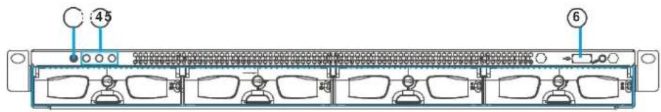
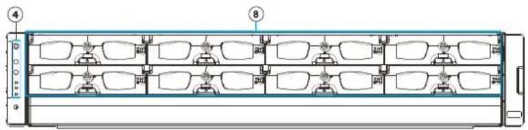
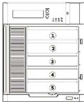
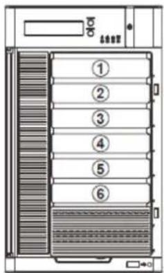
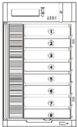
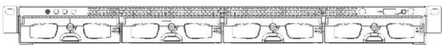
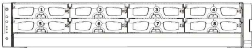
2.1. Front Panel
SMR2000 Series
SMR6000H/
8000 Series
SMR5000 Series
SMR4000U/
8000U Series
natural_image
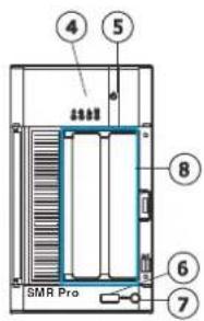
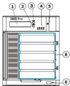
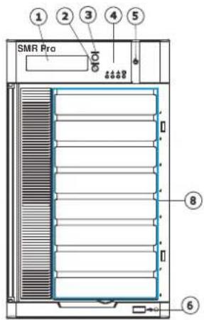
Technical diagram of a multi-chamber industrial or laboratory equipment unit with numbered components (no text or symbols visible)| Function | |
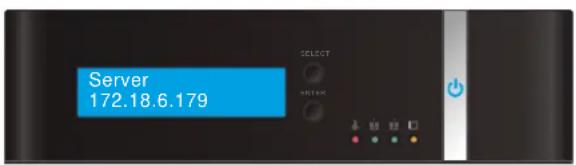
| 1. LCD Display | Shows system messages. |
| 2. Enter Switch | Confirms the options and functions after the Select Switch is used. |
| 3. Select Switch | Shows the menu for choosing RAID0, RAID1 or RAID5. Please refer to the RAID Option Table while choosing a RAID level. |
| 4. LED Indicators | Indicates the network, hard drive, and system status. |
| 5. Power Switch | Powers up the SMR. When the power is on, the power indicator will shine in blue. |
| 6. Front USB Connector | Connects external accessories such as mouse, keyboard or other external devices. |
| 7. Video Back Up Button | Reserved. |
| 8. Hard Drives Slots | Hard drive locations |
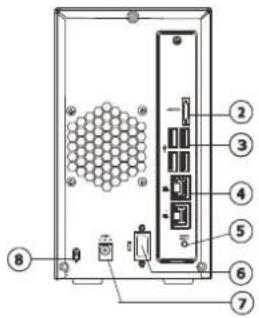
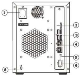
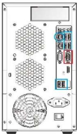
2.2. Rear Panel
SMR2000 Series
SMR6000H/
8000 Series
SMR5000 Series
SMR4000U/
8000U Series
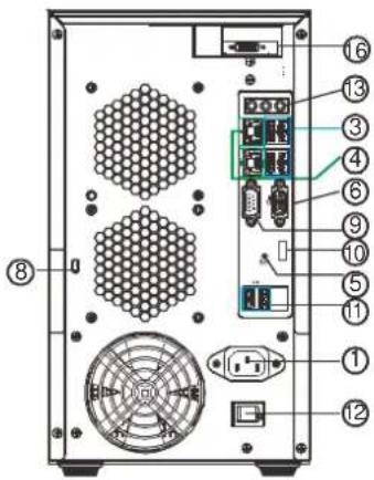
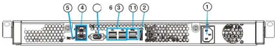
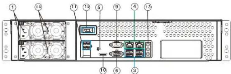
| Function | |
| 1. Power Socket | Used for connecting power cable. |
| 2. e-SATA Port x1 | Used for connecting the SMR with e-SATA drives. |
| 3. USB Port x4 | Used for exporting video clips as evidence support to external storage devices. |
| 4. LAN Port (GbE Ethernet port) x2 | Used for connecting the SMR with the network. Note that only the upper LAN port can be used. |
| 5. Restore Button | Use for reset the system to factory default. For details, please refer to the table below. |
| 6. VGA Port | Used for attaching an external monitor to the SMR. |
| 7. 12V DC Power Port | Used for connecting power cable. |
| 8. Kensington Lock-hole | For use with a Kensington lock. Please refer to your Kensington lock for instructions. |
| 9. COM Port | Reserved |
| 10. HDMI Port | Used for connecting audio/video devices such as video projectors and DVD players. |
| 11. USB Port x2 | Used for exporting video clips as evidence support to external storage devices. |
| 12. Safety Switch | Used for preventing injury if someone inadvertently attempts to open the machine. Please make sure it’s on after the power cable is attached to the power socket. |
| 13. Audio Ports | Used for attaching audio devices such as headphones and speakers. |
| 14. Power Supply Units | The two power supplies are hot-swappable and redundant. |
| 15. Power Switch | The power switch on 8000U system can be located on the rear panel. |
| 16. BNC Connector | Used for connecting analog cameras. |
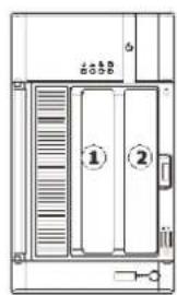
2.3. Hard Drive Designation
The hard drive arrangement for each system is shown below. The general alignment is from left to right and/or top to bottom in numeric order.
SMR2000 Series
SMR5000 Series
SMR6000H Series SMR8000 Series
SMR4000U Series
SMR8000U Series
2.4. LED Definitions
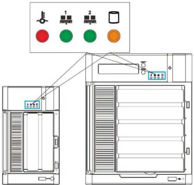
2.4.1. Desktop System Front Panel LEDs
| Name | Color | LED Status | Function | |
| Network | Green | On Indicates that power | is on and network is connected. | |
 |  | Off Indicates that network | k is disconnected. | |
 |  | Blink | Indicates that network activity is in progress. | |
| HDD | Amber On | Indicates that the hard drive can be accessed. | ||
 | Off Indicates that a hard | drive read/write error occurred. | ||
 | Blink | Indicates one of the followings:(1)Disk volume creation is in progress.(2)Online RAID level migration is in progress.(3)RAID rebuilding is in progress. | ||
| System | Red | On | Indicates the system fan is malfunctioning. | |
 | Blink | Indicates that system is starting up. | ||
 | ||||
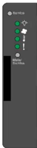
2.4.2. Rackmount System Front LED Panel
| LEDs / Button | Icon Color | Description | |
| Service LED |  | White | This LED indicates the system requires service when lit. |
| Power Status LED |  | (Normal) / Amber (Fail) | This LED is used to warn users of power supply status |
| Cooling Module Status LED |  | (Normal) / Amber (Fail) | This LED is used to warn users of cooling module status |
| Temperature Sensor Status LED |  | Green (Normal) / Amber (Abnormal) | This LED is used to warn users of temperature status |
| System Fault LED | [IMAGE] | Green (operating normally) / Amber (Warning) | This LED indicates normal operation / system failure |
| Mute and Service LED Off Button | Mute/  | Reserved |
2.4.3. Drive Tray LED
Two LED indicators are located on the right side of each drive tray. When notified by a drive failure message, you should check the drive tray indicators to find the correct location of the failed drive.
| Name | Color | LED Status | Function |
| 1. Drive Busy LED | Blue | Blink | Indicates that the data is being written to or read from the drive. |
| Off | Indicates that there is no activity on the disk drive. | ||
| 2. Power Status LED | Green / Red | On | GREEN indicates that the drive bay is populated and is working normally.RED indicates that the disk drive has failed, or a connection problem occurred. |
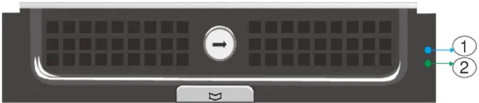
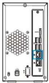
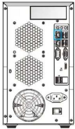
2.4.4. Rear Panel Ethernet LED
SMR2000 Series
SMR5000 Series
natural_image
Back view of a server rack unit with hexagonal grid pattern and internal components (no visible text or symbols)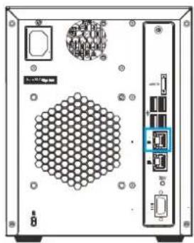
natural_image
Front view of a server rack unit with hexagonal grid pattern and ports (no visible text or symbols)SMR6000H/
SMR8000U Series
8000 Series
natural_image
Back view of a computer tower rear panel showing hexagonal grid, power connector, and fan (no text or symbols visible)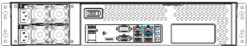
natural_image
Front view of a server rack unit with ports, connectors, and ventilation slots (no visible text or labels)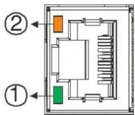
| Name | Color | LED Status | Function |
| 1. Link Status LED | Green | On | Indicates that the connection is established. |
| Off Indicates that the connection is not established. | |||
| 2. Activity LED | Amber | Blink | Indicates data transfer activity |
Chapter 3. Software Overview
3.1. Software Introduction
Video Management Software (VMS) is a highly modular and powerful video and hardware management suite that incorporates Server recording, management, and video monitoring and playback functionalities to serve the core purposes of a video surveillance system.
It operates in a client-server mode: The Local Client and Local Domain Server run for standalone SMR/NVR/VMS Server, while the Remote Client receives live video streams and event video playbacks from LAN or Internet. All administrative tasks are performed on the Client. The client software provides the ability to monitoring and playback recorded videos from multiple cameras. And for users having multiple SMR/NVR/VMS Servers, Central Management Software (its main functions are the same with the VMS) can be utilized to manage over the domain infrastructure.
3.2. Module Framework
VMS/ NVR Server
- Combines video recording, archival and retrieval functionalities for individual servers/standalone PCs.
- Serves as the connection point for client stations.
Local Domain Server
• The interface between the VMS/ VI Servers and any clients.
• User authentication server.
Local Client
- Local access, VMS Client installed on standalone PCs/SMRs for live video monitoring, event recording playback access and VMS system configuration.
■ Remote Client (full functions)
- Remote access, VMS Client installed on remote PCs for live video monitoring, event recording playback access.
- Serves as the default configuration point for NVR2000 series, which do not have a Local Client.
■ Web Client (for simple use)
- Remote access, an ActiveX application (OCX) installed on remote PCs for live viewing and event playbacks through the web browser.
■ SPhone Client (for simple use)
- SPhone Client installed on iOS/ Android devices for basic live viewing.
Web Server
- Allows user to access the live video stream, PTZ control and event recording playbacks through Microsoft Internet Explorer 7.0 (or higher) after the Web Clients components are downloaded.
VI Server
• The video intelligence processing point for a VMS solution.
- Preinstalled on SMR/NVR Server, and optional on a separate server/PC (VMS).
SCC Domain Server
- Allows centralized control over multiple Trusted VMS Server points and connections from multiple clients.
SCC Client
- Software capable of accessing multiple Trusted VMS Servers through the SCC Domain Server
3.3. System Architecture
VMS operates in scalable client - server architecture. This architecture can be divided into three types: (1) Standalone Server (2) Standalone Server + Remote Client (Web Client/ SPhone Client) (3) Multiple Servers + SCC Client.
These are the hardware requirements for using PCs as Server or Client.
| VMS Server + Client | |||
| Support NVRs | ≥ 32CH | 16~32CH | ≤ 16CH |
| OS | 64-bit:Windows 7 Professional, Enterprise, Ultimate | ||
| CPU | Intel Core i7-980X or above | Intel Core i7-860 or above | Intel Core i5-650 or above |
| Memory | 4 GB or above | ||
| Display | nVidia GeForce GTX660 2GB or above | ||
| Hard Drive | SATA 7200 RPM, 500 GB or above | ||
| Network | 1 Gbps or above | ||
| Remote Client | |||
| OS | 64-bit:Windows 7 Professional, Enterprise, Ultimate | ||
| CPU | Intel Core i7-980X or above | Intel Core i7-860 or above | Intel Core i5-650 or above |
| Memory | 4 GB or above | ||
| Display | nVidia GeForce GTX660 2GB or above | ||
| Hard Drive | SATA 72O0 RPM, 500 GB or above | ||
| Network | 1 Gbps or above | ||
| VMS Server Only | |||
| OS | 64-bit:Windows 7 Professional, Enterprise, Ultimate | ||
| CPU | Intel Core i3-530 or above | ||
| Memory | 4 GB or above | ||
| Display | On board (generic) 256MB or above | ||
| Hard Drive | SATA 7200 RPM, 500 GB or above | ||
| Network | 1 Gbps or above | ||
3.3.1. Standalone Server (Client-Server All-in-One)
For users with standalone Server, the Local Client UI is used to manage SMR Server services:
Local Client UI
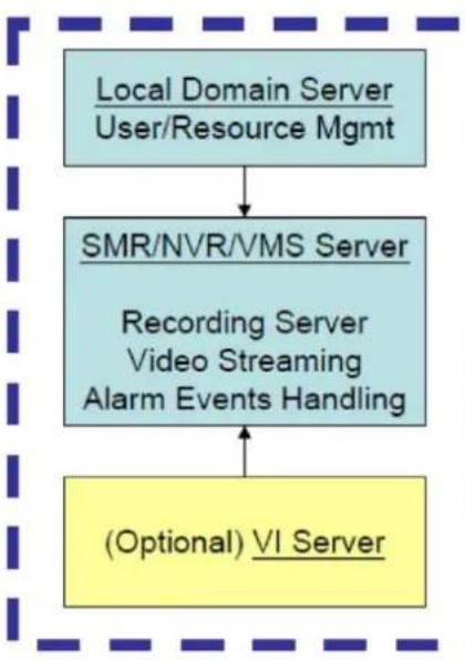
flowchart
graph TD
    A["Local Domain Server\nUser/Resource Mgmt"] --> B["SMR/NVR/VMS Server"]
    B --> C["Recording Server\nVideo Streaming\nAlarm Events Handling"]
    C --> D["(Optional) VI Server"]
-
Authentication through Local Domain Server
-
Success, access to SMR/NVR/VMS Server Services
*VI receives images from VMS Server for Video Analytic activities. In case of events, it will return warning back to VMS Server.
Application:
The Server, IP cameras are all in the same LAN.
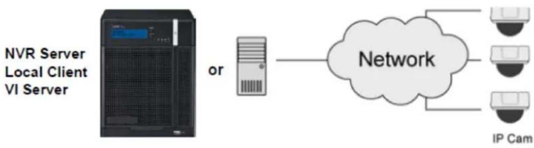
flowchart
graph LR
    A["NVR Server\nLocal Client\nVI Server"] -->|or| B["Server"]
    B --> C["Network"]
    C --> D["IP Cam"]
    C --> E["Device 1"]
    C --> F["Device 2"]
    C --> G["Device 3"]
Use SMR as Server
No installation needed.
Use PC as Server
Install both the VMS/NVR Server and VMS Client on a PC:
①Insert the VMS/ IPCAM product CD. ②Click VMS Suite on the menu to start the installation. ③Choose Typical Setup. If you don't need video analytic functions, Advanced Setup can be selected to uncheck the VI Server.
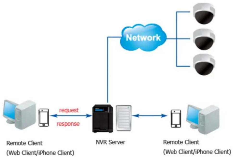
3.3.2. Standalone Server + Remote Client (Web Client/SPhone Client)
For remote users to connect to SMR/NVR Server, a remote access, VMS Client installed on remote PCs is needed for live video monitoring, event recording playback access.
Also, the Web Client, an ActiveX application (OCX) can be used for basic live viewing and event playbacks through the web browser, while SPhone Client can be used for basic live viewing on iPhone/ Android devices.
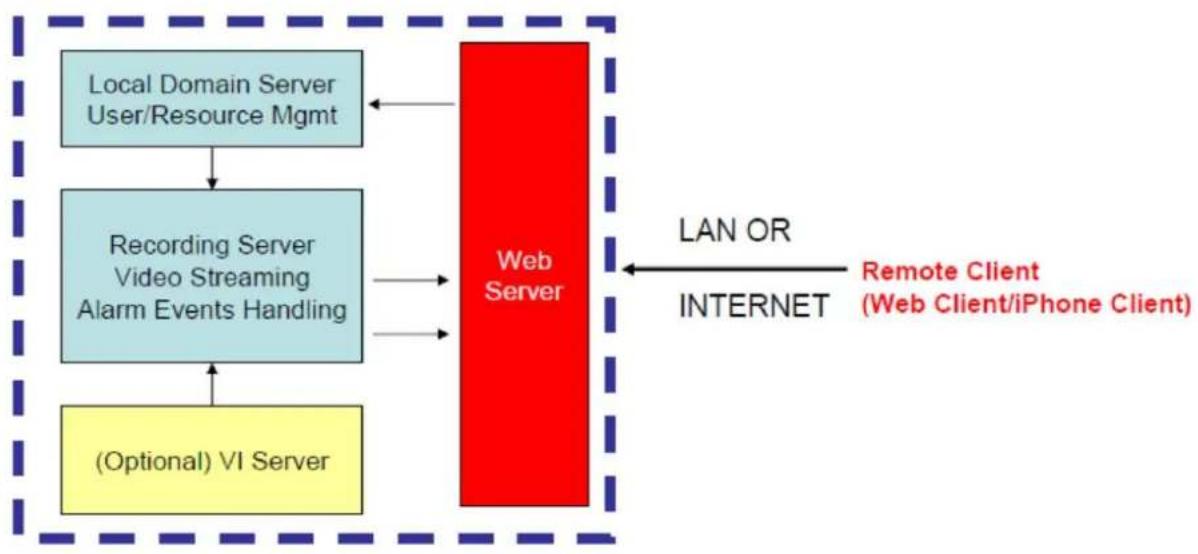
flowchart
graph TD
    A["Local Domain Server User/Resource Mgmt"] --> B["Recording Server Video Streaming Alarm Events Handling"]
    B --> C["(Optional) VI Server"]
    D["Web Server"] -->|LAN OR INTERNET| E["Remote Client (Web Client/iPhone Client)"]
    D -->|LAN OR INTERNET| F["Internet"]
    D -->|LAN OR INTERNET| G["Internet"]
Application1: Internet
The Server, IP cameras and the PC/iPhones are all in the same LAN.
flowchart
graph TD
    A["Remote Client\n(Web Client/iPhone Client)"] -->|request| B["NVR Server"]
    B --> C["Remote Client\n(Web Client/iPhone Client)"]
    B --> D["Network"]
    D --> E["Three surveillance cameras"]
    B -->|response| A
[NVR Server]
Use SMR/NVR as Server
No installation needed.
Use PC as Server
Install the VMS/NVR Server on a PC:
① Insert the VMS/ IPCAM product CD.
②Click VMS Suite on the menu to start the installation.
③Choose Advanced Setup to uncheck the VMS Client.
If you don't need video analytic functions, the VI Server can also be unchecked.
Install the Web Server on the PC:
① Insert the VMS/ IPCAM product CD.
②Click Browse CD/DVD in the menu.
③Double click WebServerSetup.exe to start the installation.
[Client]
Install the VMS Client on PCs:
①Insert the NVR/ SMR product CD.
②Click VMS Client on the menu to start the installation.
Install the Web Client on the PCs (Optional):
Launch Microsoft Internet Explorer 7.0 (or above) and enter your VMS Server IP address + "/webclient" in your web browser's URL location, eg. http://172.18.6.9/webclient to download the Web Client application.
Install the Web Client on the PCs (Optional):
Install the SPhone Client (Optional):
Download the SPhone Client from App Store on the iPhone desktop.
Install the SPhone Client (Optional)
Download the SPhone Client from App Store on the Andriod phone desktop.
Note: Please refer to Installing the VMS and Installing the Web Client for details.
Application 2: Internet
The Server, some of the IP cameras and the PC are all in the same LAN, while the other IP cameras are installed in remote location with Public IP.
![Surveon SMR2016 - [Client] - 1](/content/2026/06/1178915/images/7ebcbc3a3b38d427bbf79f0b34c4b92424058f0dda0da1257cf78f958516c1df.jpg)
flowchart
graph TD
    A["IP Camera"] --> B["Network"]
    C["Camera 1"] --> B
    D["Camera 2"] --> B
    E["Camera 3"] --> B
    F["Computer"] --> B
    G["VMS Client"] --> B
    H["VMS Server"] --> B
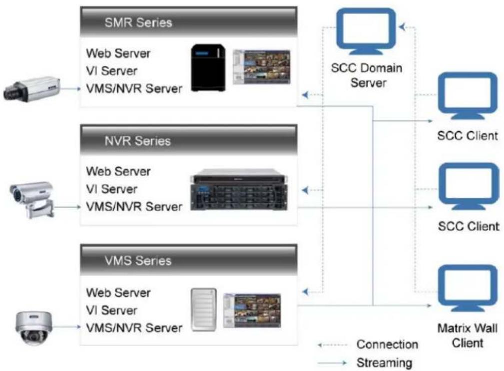
3.3.3. Multiple Servers + SCC Client
For users with multiple SMR/NVR Servers, SCC Client UI is used to manage over the domain infrastructure.
flowchart
graph TD
    subgraph_SMR_Series["SMR Series"]
        A1["Camera"] --> B1["Web Server VI Server VMS/NVR Server"]
        B1 --> C1["Server with monitor icon"]
    end

    subgraph_NVR_Series["NVR Series"]
        A2["Camera"] --> B2["Web Server VI Server VMS/NVR Server"]
        B2 --> C2["Server with monitor icon"]
    end

    subgraph_VMS_Series["VMS Series"]
        A3["Camera"] --> B3["Web Server VI Server VMS/NVR Server"]
        B3 --> C3["Server with monitor icon"]
    end

    subgraph_Matrix_Wall_Client["Matrix Wall Client"]
        D1["Server"] --> E1["SCC Domain Server"]
        E1 --> F1["SCC Client"]
        E1 --> G1["SCC Client"]
        E1 --> H1["SCC Client"]
    end

    B1 --> C1
    B2 --> C2
    B3 --> C3
    style SMR_Series fill:#f9f,stroke:#333
    style NVR_Series fill:#f9f,stroke:#333
    style VMS_Series fill:#f9f,stroke:#333

    note right of D1: Connection
    note left of E1: Streaming
Application3: Internet
(1) The Servers, IP cameras and the PCs are in LAN A.
(2) Some IP cameras are installed in LAN B, which is behind a different router in a remote location.
(3) Users are allowed to connect the SMRs/ NVRs from remote PC over the Internet.
[NVR Server]
Use SMR/NVR as Server
No installation needed.
Use PC as Server
Install the VMS/NVR Servers on PCs:
①Insert the VMS/ IPCAM product CD.
②Click VMS Suite on the menu to start the installation.
③Choose Advanced Setup to uncheck the VMS Client.
The VI Server can also be unchecked, if you don't need video analytic functions.
[VI Server] (Optional)
You can choose to install the VI Server only on a standalone PC to manage the video intelligence data.
①Insert the VMS/ IPCAM product CD.
②Click VMS Suite on the menu to start the installation.
③Choose Advanced Setup to choose VI Server only.
[SCC Domain Server]
Install the SCC Domain Server on a PC:
①Insert the NVR/ SMR product CD.
②Click SCC Suite on the menu to start the installation.
③Choose Advanced Setup to select the SCC Domain Server only.
[SCC Client]
Install the SCC Client on PCs:
①Insert the NVR/ SMR product CD.
②Click SCC Suite on the menu to start the installation.
③Choose Advanced Setup to select the SCC Client only.
Note: (1) For users don't have Surevon SMR/NVR series, please contact your dealer for the SCC installation file. (2) The SCC Domain Server can also be installed together with the SCC Client in the same PC by choosing Typical Setup. (3) Please refer to Installing the VMS and Installing the SCC for details.
3.3.4. Network Requirements
In order to preserve enough bandwidth for surveillance video, a surveillance network is presumed to be free of user/business traffic. Server software currently supports Class B and Class C type addresses. Currently the Server software only searches for Servers on the same subnet. Cameras should also reside on the same subnet.
Opening Ports
If access through a firewall in a local network is required, try opening the following ports: SMTP (25), HTTP (80), FTP (20, 21), OMNI (2809), HTTPS (443) and RTSP (554, 8554.). Other ports should also be opened while using port forwarding to access the VMS Server: Stream Port (9090), Doman Data Port (9060), Log Download Message Port (15507) and Log Download Data Port (9080).
Note: Please refer to Port Forwarding Section for more details.
Warnings / Precautions
If the Server and a VMS client reside on separate subnets, please set up gateway, VLAN, or cross-subnet routing to bridge surveillance traffic. Please consult with a network administrator for problems with network setups. A VMS client needs to be rebooted when network settings are changed.
3.4. Port Forwarding
Port forwarding is a name given to the combined technique of:
- Translating the address and/or port number of a packet to a new destination.
- Possibly accepting such packet(s) in a packet filter (firewall).
- Forwarding the packet according to the routing table.
To illustrate its concept, two computers on the Internet that communicate with each other using TCP/IP or UDP/IP protocols(though the process is not limited to these) utilize ports to identify the opposite connection points of each other where the data packets supposed to go to. In order to communicate, each computer knows the port of another computer (in addition to IP address) and sends the data to that port. Port forwarding forwards these ports in such a way that when one computer sends data to the specific port of another computer, the data is actually sent to a different port. This allows remote computers to connect to a specific computer or service within a private LAN.
In a typical residential network, nodes obtain Internet access through a DSL or cable modem connected to a router or network address translator (NAT/NAPT). Hosts on the private network are connected to an Ethernet switch or communicate via a wireless LAN. The NAT device's external interface is configured with a public IP address. The computers behind the router, on the other hand, are invisible to hosts on the Internet as they each communicate only with a private IP address.
When configuring port forwarding, the network administrator sets aside one port number on the gateway for the exclusive use of communicating with a service in the private network, located on a specific host. External hosts must know this port number and the address of the gateway to communicate with the network-internal service.
When used on gateway devices, a port forward may be implemented with a single rule to translate the destination address and port. The source address and port are, in this case, left unchanged. When used on machines that are not the default gateway of the network, the source address must be changed to be the address of the translating machine, or packets will bypass the translator and the connection will fail.
3.4.1. Port Forwarding for Accessing VMS Server
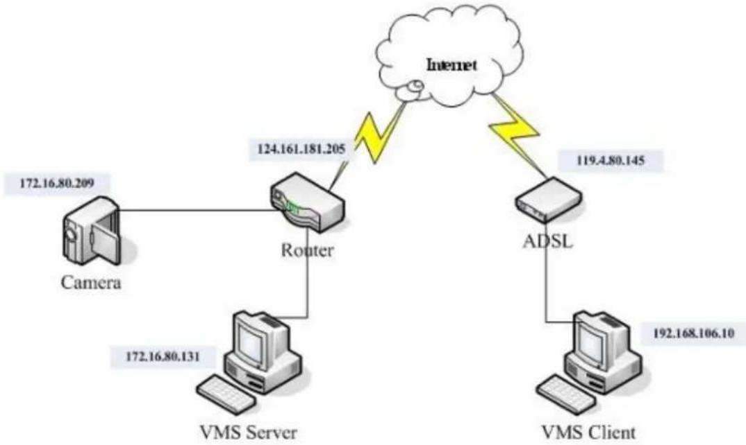
flowchart
graph TD
    A["Camera"] -->|172.16.80.209| B["Router"]
    C["VMS Server"] -->|172.16.80.131| B
    B -->|124.161.181.205| D["Internet"]
    D -->|119.4.80.145| E["ADSL"]
    E -->|192.168.106.10| F["VMS Client"]
To enable port forwarding for accessing VMS Server, please follow the steps below:
- Do Router Port Mapping for VMS/NVR Server
Go to Setup > Other Tasks > Server > Router Port Mapping in VMS after it is installed.
Note: The VMS/ NVR Server is preinstalled in NVR2000/ SMR Series.
A Router Port Mapping window will prompt for entering port numbers. Please put in the numbers as listed below:
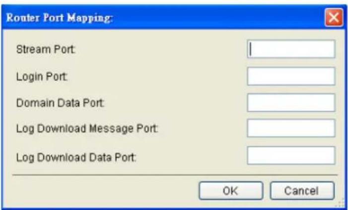
Stream Port: 9090
Login: Port: 2809
Doman Data Port: 9060
Log Download Message Port: 15507
Log Download Data Port: 9080
2. Open Ports on the Router
Host Ports: The private ports that the internal VMS/NVR Server use, which are unchangeable.
Global Ports: The public ports for remote clients to connect to the internal VMS/NVR Server. The Global ports are changeable, but the simplest way is to make them the same with the host ports.
Please open the listed ports on your router:
| Port(Host/Global Port) | Protocol | Port Number |
| Domain Message Port | UDP | 9050 |
| Domain Data Port | TCP | 9060 |
| Login Port | TCP | 2809 |
| Stream Port | TCP | 9090 |
| Log Download Message Port | TCP | 15507 |
| Log Download Data Port | TCP | 9080 |
Web Management Platform
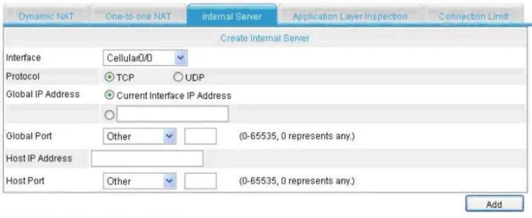
Select the internal server(s) you want to remove
| Interface | Global IP Address | Global Port | Host IP Address | Host Port | Protocol |
| Ethernet0/0 | current-interface((0.0.0.0) | 9060 | 192.168 1.2 | 9060 | TCP |
| Ethernet0/0 | current-interface((0.0.0.0) | 9050 | 192.168.1.2 | 9050 | UDP |
| Ethernet0/0 | current-interface((0.0.0.0) | 2809 | 192.168.1.2 | 2809 | TCP |
| Ethernet0/0 | current-interface((0.0.0.0) | 15507 | 192.168.1.2 | 15507 | TCP |
| Ethernet0/0 | current-interface((0.0.0.0) | 9080 | 192.168.1.2 | 9080 | TCP |
| Ethernet0/0 | current-interface((0.0.0.0) | 9090 | 192.168.1.2 | 9090 | TCP |
| Ethernet0/0 | current-interface((0.0.0.0) | 9060 | 192.168 1.7 | 9060 | UDP |
Delete
Note: Camera port (default: 80) and stream port (default: 6002) for accessing cameras should be opened while VMS/NVR Server and the cameras and are not in the same LAN.
Chapter 4. Installation
4.1. Before You Start
4.1.1. Checklist for Operating Environment
Users need to prepare the following devices to set up the surveillance system.
| Network Video Recorder | SMR series |
| IP Camera | Network Cameras (such as CAM2320) |
| Network | Existing LAN, Switch, Router or Hub (please see the Network Topology below) |
| Storage | Hard Drives |
Note: The hard drives should be purchased separately.
4.1.2. Checklist for Network Topology
Make sure you have the right switch/hub for your environment. Either of the following options will work.
| Common Topology | Reference Product | |
| Existing LAN | LAN Switch with DHCP Server | Office LAN |
| Router | LAN Switch with build-in DHCP Server | D-Link DIR-130 |
| Switch/ Hub | No DHCP Server(refer to the Note below) | D-Link DES-1108 |
Note: For devices without DHCP Server function, please refer to Configuring DHCP Service Section.
4.2. Hard Drive Installation
4.2.1. Hard Drive Installation Prerequisites
Purchase hard drives having the same capacity and using same interface with the pre-installed ones.
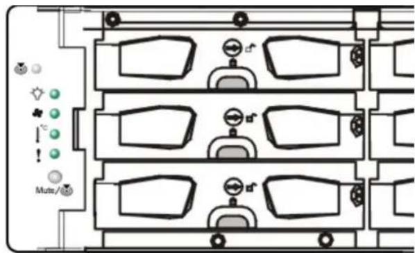
4.2.2. Inserting Hard Drive into Drive Tray (Desktop Series)
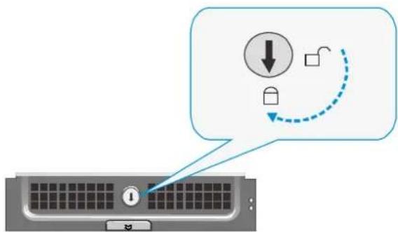
- Open the front panel of the SMR system.
- Press the release button (indicated by the blue arrow) on the bezel, the bezel panel should open automatically and gently pull out the hard drive tray.

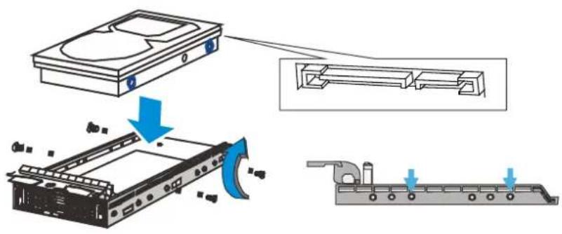
- Place the hard drive into the drive tray. Make sure the hard drive's interface connector is facing the open side of the drive tray and its label side facing up. Adjust the drive's location until the mounting holes in the drive tray are aligned with those on the hard drive. Secure the drive with four supplied flat head screws.
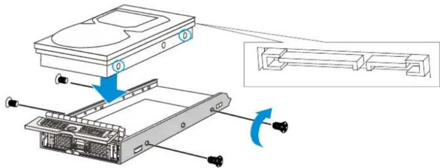
- With the tray bezel open, insert the hard drive and tray into the system enclosure.
natural_image
Diagram of an open computer tower showing internal hardware and ventilation slots (no text or labels)- Close the tray bezel.
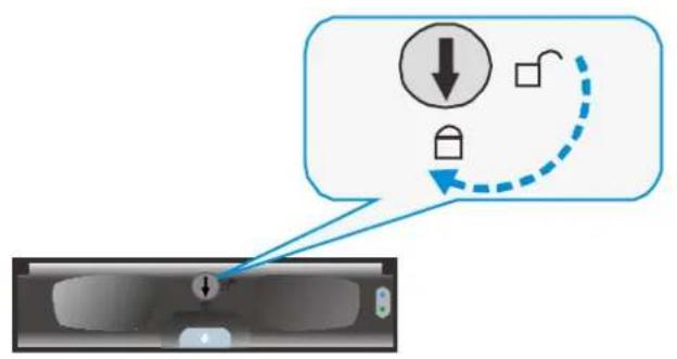
natural_image
Technical diagram of a mechanical assembly with internal components and motion indicator (no text or symbols)- Use the small flat blade screwdriver to turn the bezel lock from the unlock to lock position.
-
Repeat above steps to install other hard drives.
-
Close the system front panel when you are done installing hard drives.
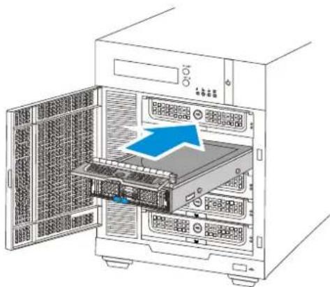
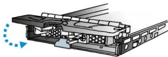
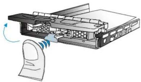
4.2.3. Inserting Hard Drive into Drive Tray (Rackmount Series)
- Remove the tray from the enclosure, press the release button and gently pull out the tray.
natural_image
Diagram of a computer tower with a finger pointing to a device, showing internal components and a scroll wheel (no text or symbols)- Place the hard drive into the drive tray. Make sure the hard drive's interface connector is facing the open side of the drive tray and its label side facing up. Align the drive and the mounting holes on the tray.
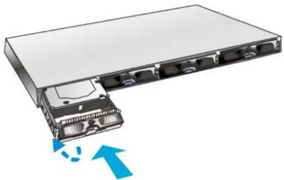
- With the tray bezel open, insert the installed hard drive and tray into the enclosure. Once inserted, close the tray bezel.
natural_image
Illustration of a server rack with an open rear panel and blue directional arrows indicating data flow (no text or symbols)- Use a small flathead screwdriver to rotate the tray bezel lock from the unlock position to the lock position.
4.3. System Connections
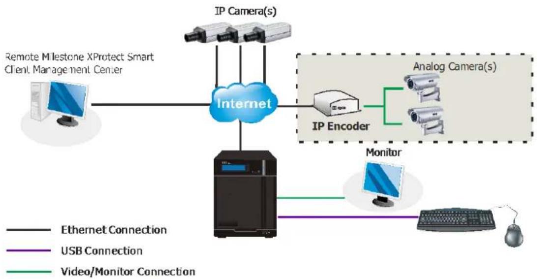
flowchart
graph TD
    A["Remote Milestone XProtect Smart Client Management Center"] --> B["Internet"]
    C["IP Camera(s)"] --> B
    D["IP Encoder"] --> B
    E["Analog Camera(s)"] --> B
    F["Monitor"] --> B
    G["Computer"] --> B
    H["Mouse"] --> B
    I["Ethernet Connection"] --> B
    J["USB Connection"] --> B
    K["Video/Monitor Connection"] --> B
Note: Shaded areas are optional devices.
Connect cables to the rear panel ports as follows:
SMR2000 Series
natural_image
Back panel of a server rack with hexagonal grid and internal components (no visible text or symbols)SMR6000H/
8000 Series
SMR5000 Series
natural_image
Back view of a server rack unit with hexagonal mesh panel and control panel (no visible text or symbols)SMR8000U Series
natural_image
Back view of a computer tower with hexagonal grid patterns, ventilation fan, and labeled connectors (no readable text or symbols)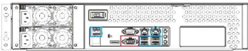
natural_image
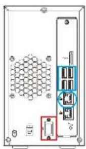
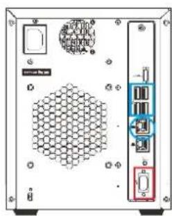
Front view of a server rack unit with ports, connectors, and ventilation slots (no visible text or labels)- Insert mouse, keyboard or other external devices to the USB port (blue rectangles) for operating the Video Management Software (VMS).
- Insert the LAN cable to the upper LAN port (blue circles) to connect the SMR to a local network where your IP cameras reside.
(Connection to analog cameras is also available via an IP encoder.)
■ Connect an external monitor capable of 32bit or higher color quality to the VGA Port (red rectangles) to view the VMS interface.
4.4. Powering up SMR
4.4.1. SMR Desktop Systems
- Attach the power cable to the power socket on the rear panel.
- (SMR6000H/ 8000 Series) Make sure the safety switch on the rear panel is switched to the “-” side, which means that it is turned on.
- Press the Power Switch.
- See if the System LED is blinking, which means the system is starting up.
- See if the Network LED has turned green, which indicates power is on and network is connected.
- See if the HDD LED is on, which means the hard drive can be accessed.
- (SMR5000/ 6000H/ 8000 series) The Server name and the IP address will be shown on the LCD screen.
4.4.2. SMR Rackmount Systems
- Press the Power Switch and a beep sound should follow.
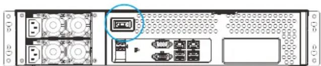
natural_image
Back panel of a network equipment unit showing ports, connectors, and storage areas (no visible text or labels)- When powered on, the service LED should remain off while the rest of the status LEDs on the front panel should light up green to indicate normal operation.
Service LED: Off
Power LED: Green
System fault LED: Green
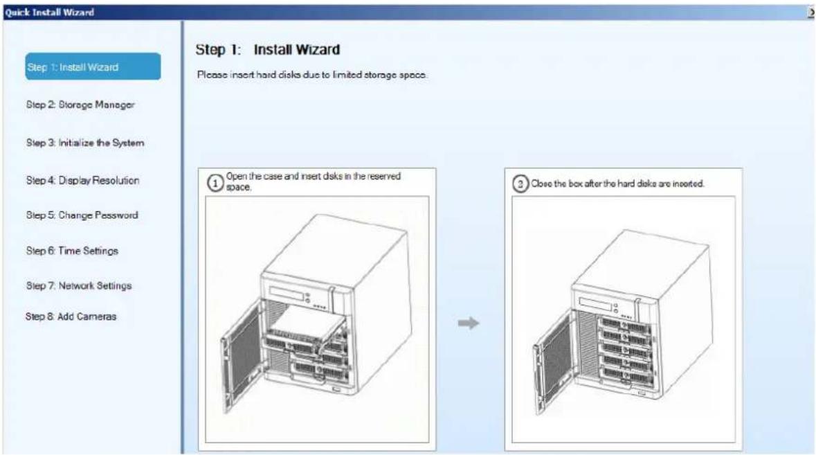
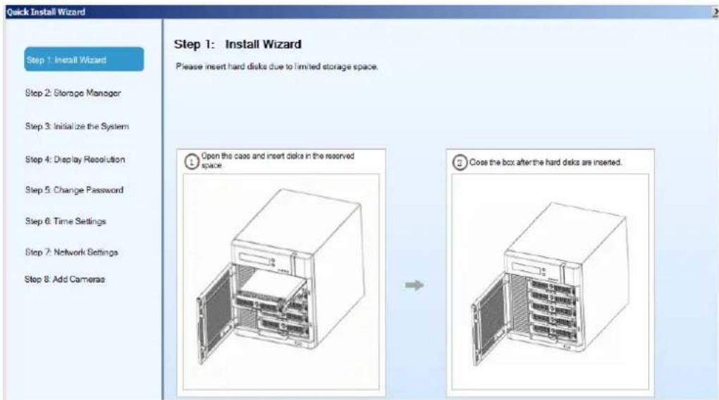
4.5. Install Wizard
When you run the SMR series for the first time, you need to go through the following steps within the Quick Install Wizard after logging in.
- Make sure the hard drives are inserted into the SMR case. Click Next to continue.
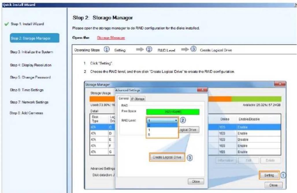
2. Click Storage Manager to do RAID configuration.
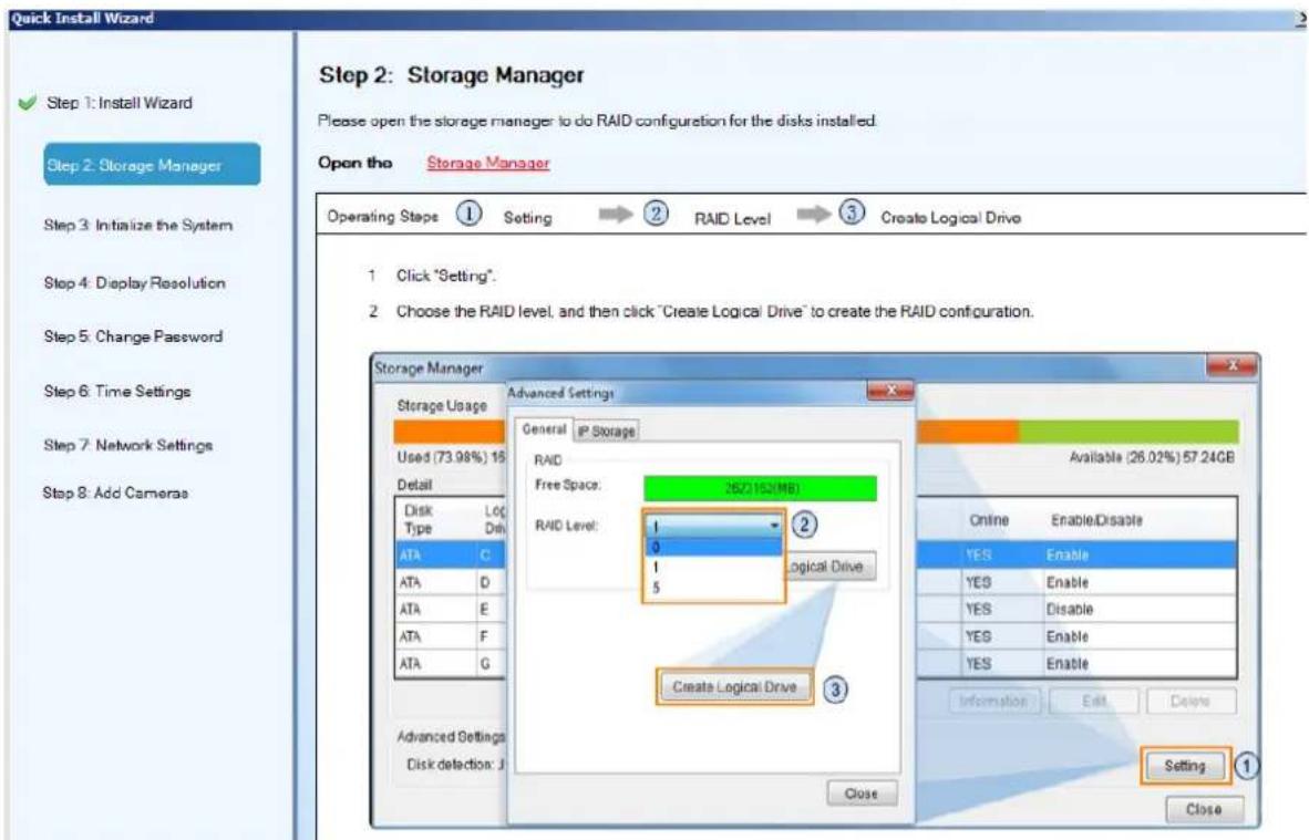
Click Setting, choose the RAID level in the Advanced Settings dialogue, and then click Create Logical Drive to create the RAID configuration.
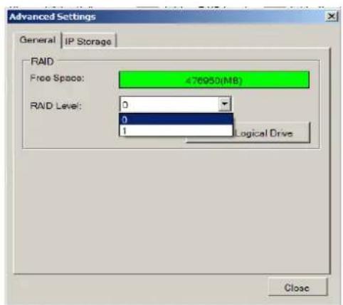
WARNING
All hard disk data will be erased.
These are the RAID options for SMR models.
| Minimum Hard Drives | RAID Options | Descriptions |
| 2 | RAID0 | Provides no protection, but offers maximum capacity. |
| 2 | RAID1 | Provides best protection. Your data will be mirrored. |
| 3 | RAID5 | Provides protection against one drive failure. |
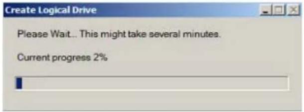
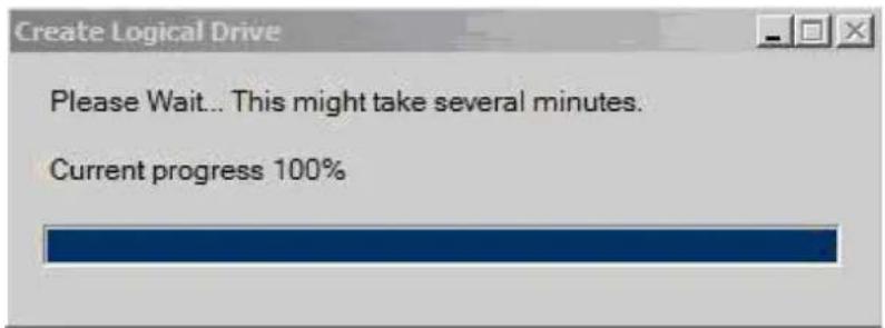
Please click OK after the configuration is done, and the system will reboot automatically. About 2 minutes later, the Wizard window will appear again. Click Next to continue.
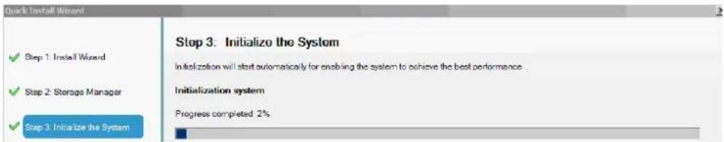
- System initialization will start.
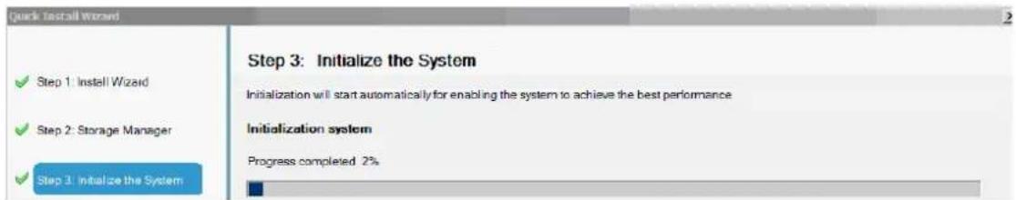
The system will shut down after the initialization is done successfully. Please click OK.
Press the power switch to restart the system. About 1.5 minutes later, the Wizard window will pop up again.
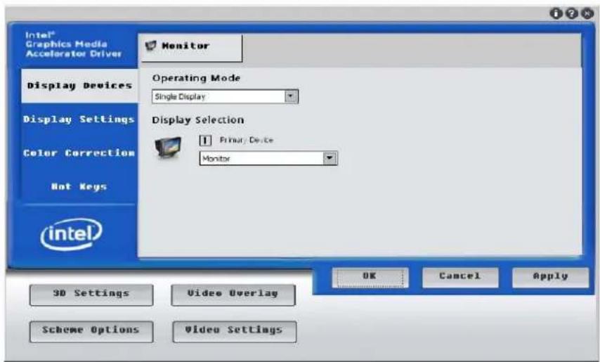
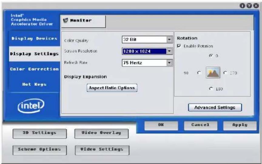
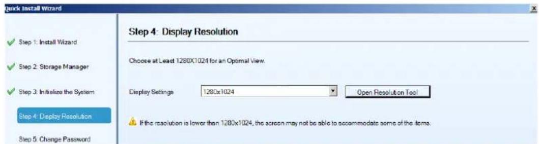
- The recommended monitor resolution for the SMR is 1280x1024. Click Open Resolution Tool to change the resolution setting.
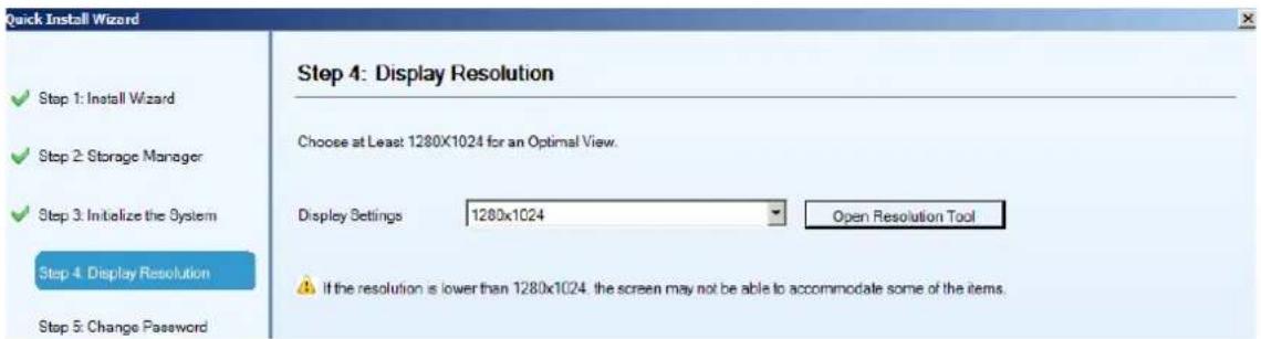
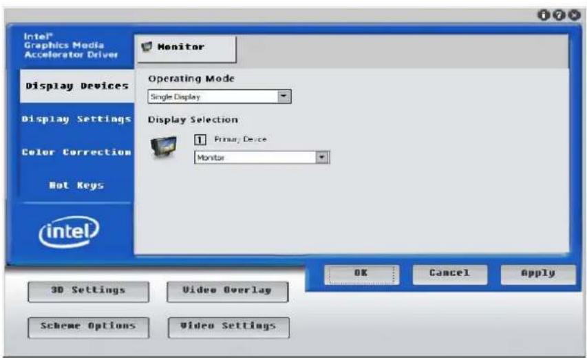
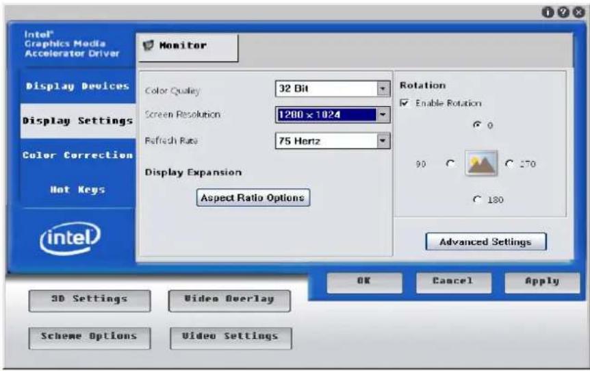
Choose Single Display as the operating mode and Monitor as the display selection in Primary Device. Change the screen resolution in Display Settings. Click OK to finish.
Note: SMR8000 series support dual monitor display.
Click Next to continue.
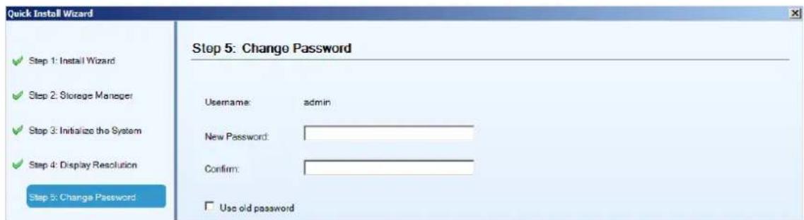
- The default password for SMR login is admin. If you want to change the password, please enter a new one in both the blanks of New Password and Confirm.
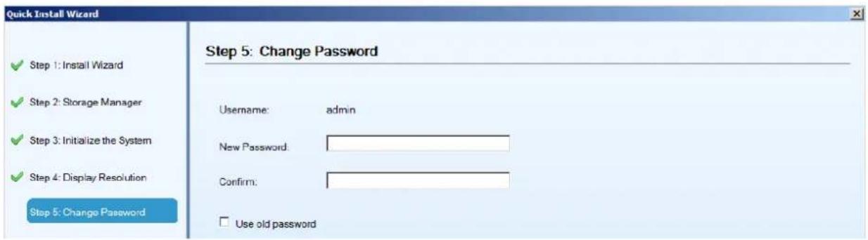
If you want to keep using the default password, please tick Use old password.
Click Next to continue.
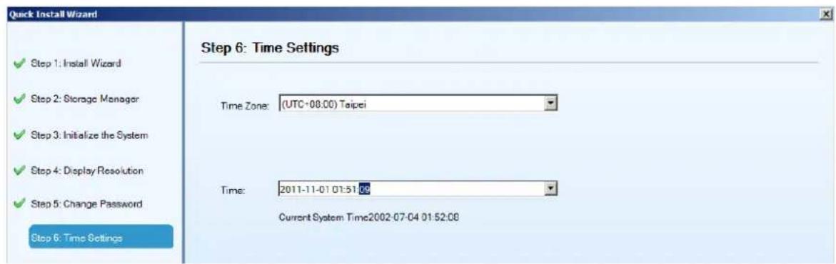
- Choose the time zone and set the actual date and time for the SMR system.
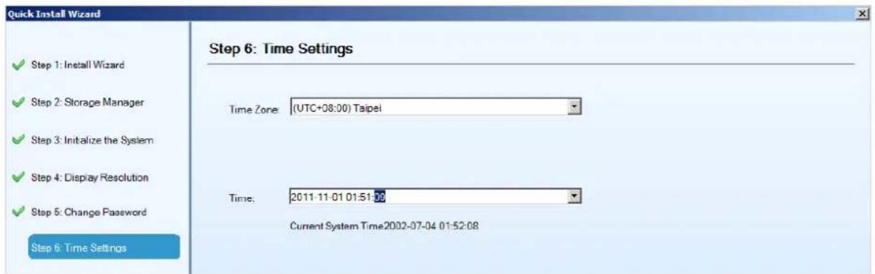
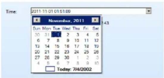
Click Next to continue.
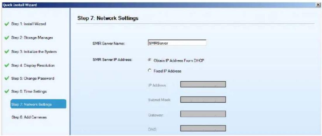
- Set an IP address for the SMR Server. Obtaining the IP address from DHCP is recommended.
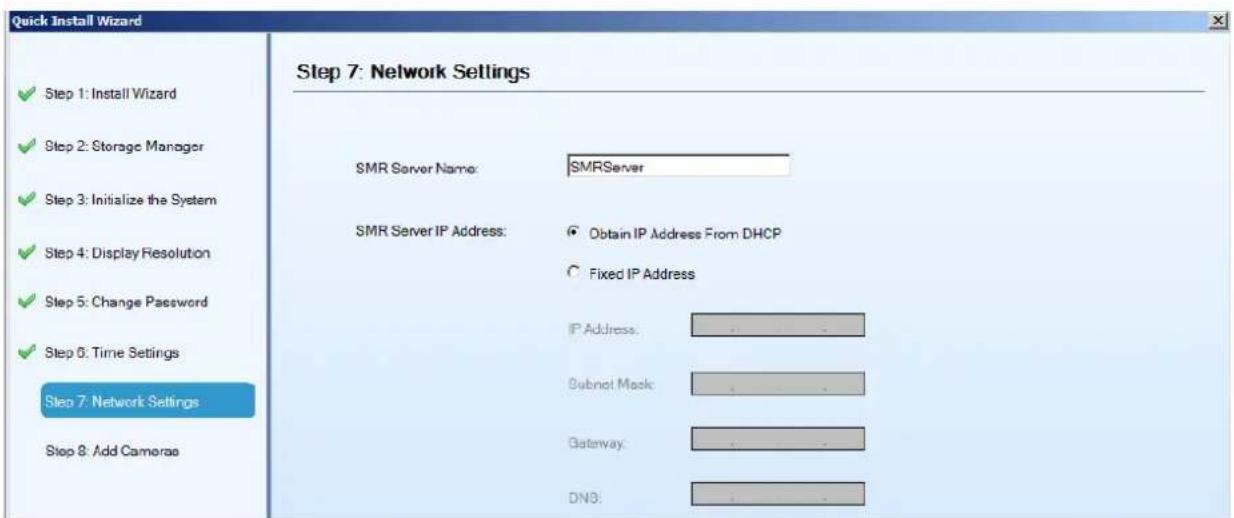
The IP will change after the system is restarted.
Click Next to continue.
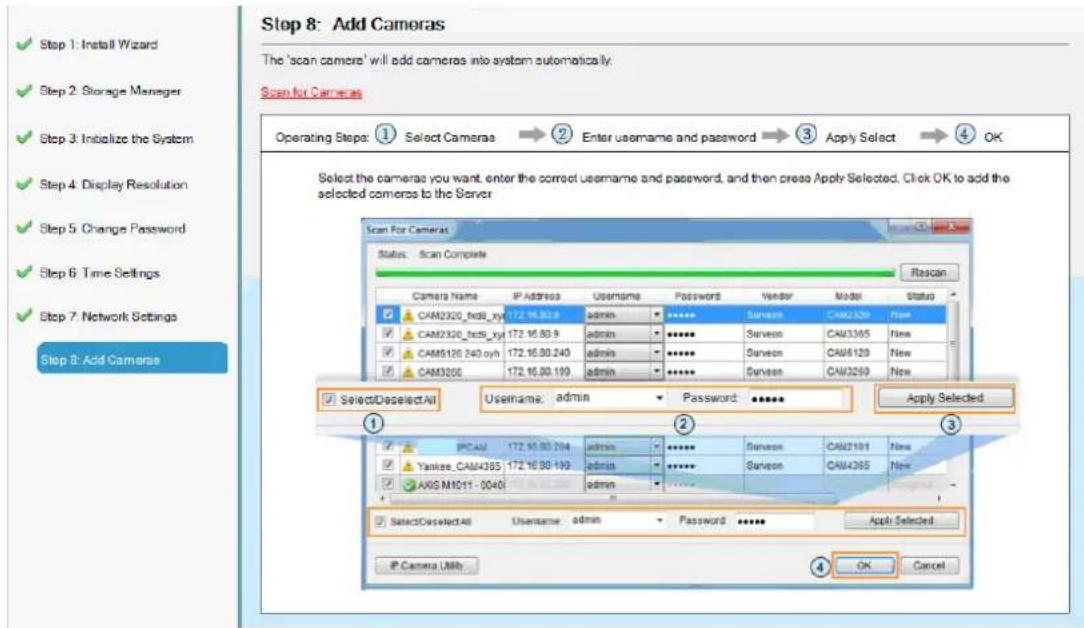
8. Click Scan for Cameras to add cameras to the SMR server.
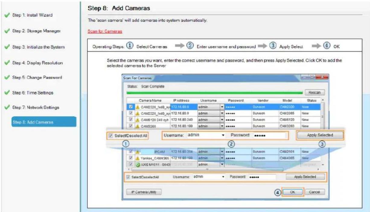
The cameras that can be added to the Server will be displayed.
To add a camera to the system, check the box by the camera entry. You may also check the Select All box at the bottom of the window to select all the cameras found.
Enter the username and password, and press Apply Selected. Click OK to add the selected cameras to the Server.
-
Click Finish to end the wizard.
-
The VMS will start automatically after the wizard is finished.
4.6. Software Installation
4.6.1. Installing the VMS
Note: For NVR2000/ SMR series, users have to install VMS Client on remote PC(s) when distant live viewing and playback are needed.
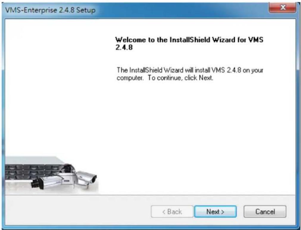
- Insert the VMS/ IPCAM CD-ROM. The CD should autorun. If it does not, open the CD manually and double-click autorun.exe. The menu below will be displayed.
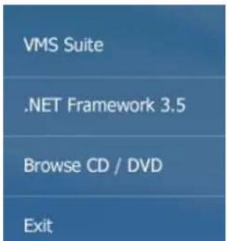
Click VMS Suite to start the installation.
- Choose a setup type from Typical and Advanced. Then Click Next when you are satisfied with your selection.
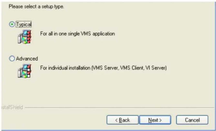
- You may choose to install among the following while Advanced Setup Type is selected:
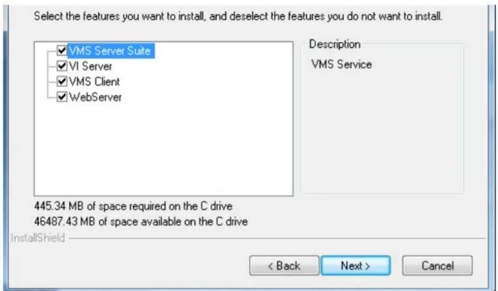
-
VMS Server Suite - Includes the VMS Server and Local Domain Server, VI Server and VMS Client.
VI Server
VMS Client
Web Server -
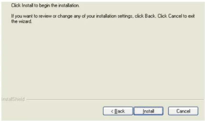
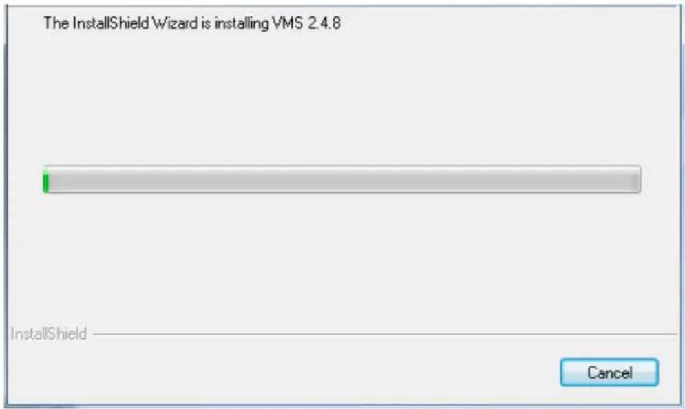
The confirmation screen will display. Click Install. A progress bar will display, indicating installation progress.
- When installation is finished, an informational screen will display. Click Finish to complete installation.
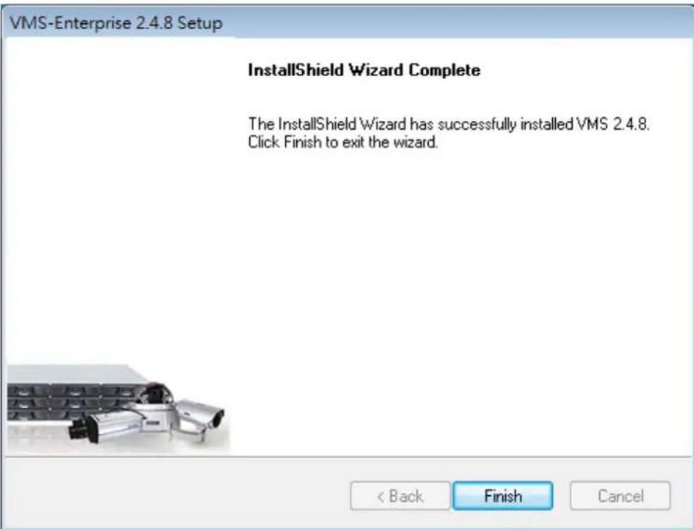
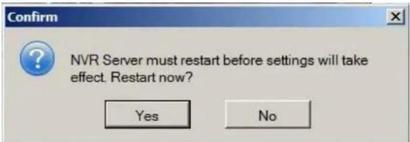
- The system will prompt for a restart. A restart is required before the VMS will function correctly. You may choose to immediately automatically restart your computer, or restart your computer later. Clicking Finish will apply your choice.
VMS-Enterprise 2.4.8 Setup
InstallShield Wizard Complete
Setup has completed installation of VMS 2.4.8.
Yes, I want to restart my computer now.
No, I will restart my computer later.
A restart is required before VMS can be used.
natural_image
Close-up of a metallic mechanical component with internal cavities and mounting holes (no visible text or symbols)< Back
Finish
Cancel
4.7. Starting the VMS Client
To start the software, click Programs > VMS Suite > VMS Client under the
Windows Start menu.
The software will prompt for the following information:
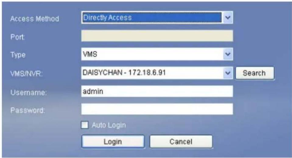
- Access Method – Directly Access or Internet Port Forward.
Type - Choose VMS.
Server - The IP address for the VMS/NVR Server. You can click Search button to obtain it. For users of port forwarding, it should be the IP address of the router. - Port - The Login Port for port forwarding - 9050. It should be set under Server > Other Tasks > Port Mapping after the first login.
Note: (1) Please refer to Port Forwarding Section for more details. (2) SCC does not support port forwarding functionalities.
- Username – The username for the domain, which is always admin.
- Password – The password for the domain. Default password is admin.
Click Login after the password (and port number) is entered.
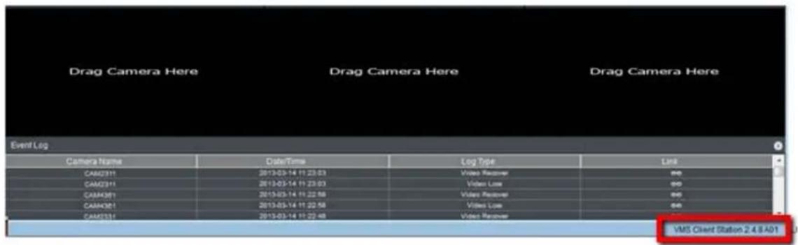
4.7.1. Checking the Software Version
Users can see the software version at the lower right corner of the window after logging in.
4.7.2. Logging out
The Client can be logged out of all the Servers configured on the system by pressing the Logout button on the upper right hand corner in the GUI. Logging out of individual servers can be achieved by double clicking the server entry and clicking the Yes button on the confirmation screen.
Closing the window using the X button on the top right corner will exit the Client. A confirmation screen will appear, click Yes to exit the system.
Note: (1) If the system becomes unresponsive, users can force shutdown the system (press and hold the power until the system shuts down). This should only be done when the system is unresponsive!
Chapter 5. Reinstallation
5.1. Reset RAID
The actions of reset RAID (to change the RAID type or clear video data in the RAID) and reset the whole system (to reinstall the OS) would require a reinstallation on your SMR.
Note: (1) RAID from other vendors is not compatible.
(2) Make sure the deploying disks are NON-RAID and unformatted before reinstallation.
(3) Reinstallation functionality is for SMR2000/4000U/5000/6000H only.
(4) SMR8000 and NRV21000 do not support OS reinstallation.
Steps to rest RAID:
- Press "Ctrl + I" to enter the RAID bios to boot up SMR.
Note: RAID bios window will appear after pressing "Ctrl + I".
- Select "3. Reset Disk to NON-RAID" and then press "Enter".
![Intel(R) Rapid Storage Technology - Option ROM - 18.6.8.1001 Copyright(C) 2003-11 Intel Corporation. All Rights Reserved. [ MAIN MENU ] 1. Create RAID Volume 2. Delete RAID Volume 4. Recovery Volume Options 5. Acceleration Options 6. Exit [ DISK/VOLUME INFORMATION ] RAID Volumes: None defined. Physical Devices: Port Device Model Serial # 0 Hitachi HUA72302 MK0A31YHGZL21A 1 Hitachi HDS72202 JK11A5B8XM6V3X 2 Hitachi HUA72201 JPW9K0J88HL2ML Size Type/Status(Vol ID) 1.8TB Non-RAID Disk 1.8TB Non-RAID Disk 931.5GB Non-RAID Disk [++]-Select [ESC]-Exit [EHTKB]-Select None HannsG](/content/2026/06/1178915/images/c866eb0856cd9f1fd6309baddc8422c737572bdfd7230ca51c25b8b46857ceac.jpg)
- Use the space bar on your keyboard to select the hard disk drives you'd like to reset.
![HW191A Intel(R) Rapid Storage Technology - Option ROM - 10.6.0.1091 Copyright(C) 2003-11 Intel Corporation. All Rights Reserved. [ MAIN MENU ] 1. Create RAID Volume [ RESET RAID DATA ] Resetting RAID disk will remove its RAID structures and revert it to a non-RAID disk. WARNING: Resetting a disk causes all data on the disk to be lost. (This does not apply to Recovery volumes or Cache disks) Port Drive Model Serial ■ Size Status ▶0 Hitachi HUA723820ALA MX0A31YHGZL21A 1.8TB Member Disk ▶1 Hitachi HDS722820ALA JK11A5BBXMGV3X 1.8TB Member Disk ▶2 Hitachi HUA722818CLA JP49KBJDBKLZML 9.31.5GB Member Disk Select the disks that should be reset. [↑↓]-Previous/Next [SPACK]-Selects [ENTER]-Selection Complete [↑↓]-Select [ESC]-Exit [ENTER]-Select Menu](/content/2026/06/1178915/images/43d2c412a161a7833c26127545b3703537efa32b64f55160f363770c9d1fe613.jpg)
- Once selected, press "Enter" and type "Y" to confirm and reset the selected hard disk drive to NON-RAID.
![Intel(R) Rapid Storage Technology - Option ROM - 10.6.0.1091 Copyright(C) 2003-11 Intel Corporation. All Rights Reserved. [ MAIN MENU ] 1. Create RAID Volume 4. Recovery Volume Options [ RESET RAID DATA ] Resetting RAID disk will remove its RAID structures and revert it to a non-RAID disk. WARNING: Resetting a disk causes all data on the disk to be lost. (This does not apply to Recovery volumes or Cache disks) Port Drive Model Serial # ▶0 Hitachi HUA723B20ALA MK0A31YHGZLZ1A 1.8TB Member Disk ▶1 Hitachi HDS722B20ALA JK11A5B0XM6V3X 1.8TB Member Disk ▶2 Hitachi HUA722B10CLA JPW9K0J80HLZML 931.5GB Member Disk Are you sure you want to reset RAID data on selected disks? (Y/N): [↑↓]-Previous/Next [SPACE]-Selects [ENTER]-Selection Complete [↑↓]-Select [ESC]-Exit [ENTER]-Select Menu](/content/2026/06/1178915/images/4cc3c85d72a3b714c56e3bf7831eee600d27618bd9bbefbeecf0fc25ba5d45d6.jpg)
Once the reset is done, the hard disk drive will appear as NON-RAID Disk.
![Intel(R) Rapid Storage Technology - Option ROM - 18.6.8.1891 Copyright(C) 2003-11 Intel Corporation. All Rights Reserved. [ MAIN MENU ] 1. Create RAID Volume 2. Delete RAID Volume 4. Recovery Volume Options 5. Acceleration Options 6. Exit [ DISK/VOLUME INFORMATION ] RAID Volumes: None defined. Physical Devices: Port Device Model Serial # 0 Hitachi HUA72302 MK8A31YHGZL21A 1 Hitachi HDS72202 JX11A5B0KM6V3X 2 Hitachi HUA72201 JPW9K0J80HL2ML Size Type/Status(Vol ID) 1.0TB Non-RAID Disk 1.0TB Non-RAID Disk 931.5GB Non-RAID Disk [↑↓]-Select [ESC]-Exit [BMYEN]-Select Menu HannsG](/content/2026/06/1178915/images/cb4401dc1b53df203227103e17a5a946db063ca10acc7eddea8d025c5b50f029.jpg)
- Press "ESC" to exit and then turn the SMR off to activate the settings.
5.2. Reset the Whole System
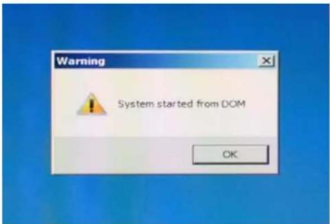
- Before power on the SMR, please take out the existing hard disk drive to trigger system starts from DOM.
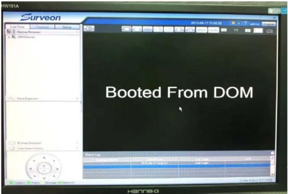
- Switch on your SMR and you will see the "System started from DOM". Click "OK" to login.
- Login VMS.
- You will see a popup dialog asking you to configure the video path. Click "No". You will see the following image.
- After that, you will see the Install Wizard as the image shown below. If the install Wizard does not run automatically, click F4 to launch.
- Insert an unformatted hard disk drive into the SMR and click "Next" button. If the hard disk that requires a reset is already in your SMR, click "Next" button to proceed.
- Skip "Step2: Storage Manager" if you want to keep your old videos and RAID system.
Select the "Step2: Storage Manager" to set RAID configuration and go to the "Step 3: Initialize the System".
- Click Setting, choose the RAID level in the Advanced Settings dialogue, and then click Create Logical Drive to create the RAID configuration.

WARNING
All hard disk data will be erased after this step.
These are the RAID level options for SMR models.
| Minimum Hard Drives | RAID Options | Descriptions |
| 2 | RAID0 | Provides no protection, but offers maximum capacity. |
| 2 | RAID1 | Provides best protection. Your data will be mirrored. |
| 3 | RAID5 | Provides protection against one drive failure. |
- After the configuration is done, click OK, and the system will reboot automatically.


System must be restart after hardware configuration changed

- About 2 minutes later, the Install Wizard will appear again. Click Next to continue.
- In the "Step 3: Initialize the System", after restart, login to your SMR and the system initialization will start.
- After the initialization is done, the system will ask you to shutdown the SMR. Click OK and turn the power off and on manually. The Install Wizard will appear again after power on.
- Press the power switch to restart the system. About 1.5 minutes later, the Install Wizard will appear again.
- In the "Step4: Display Resolution", the recommended monitor resolution for the SMR is 1280x1024. Click Open Resolution Tool to change the resolution setting. If the resolution does not require a change, click "Next" and skip the "Step4: Display Resolution".
- Select Single Display as the operating mode and Monitor as the display selection in Primary Device. Change the screen resolution in Display Settings. Click OK to finish.
Note: SMR8000 series support dual monitor display.
- Click Next to continue.
- In the "Step 5: Change Password", If you want to change the password, please enter a new set in the blanks of New Password and Confirm. If you want to use the old password, just check on the option "Use Old Password". Click Next to continue.
- In the "Step 6: Time Settings", select the time zone and set the actual date and time the same as your region's time and date. If the date and time are incorrectly set, the functionality of VI, playback and schedule may not work properly. Click Next to continue.
- In the "Step 7: Network Settings", set the IP address for the SMR server. It is recommended to Obtain the IP Address From DHCP. Click Next to continue.
- In the "Step 8: Scan for Cameras", add cameras to the SMR server.
- The available cameras will be listed. Check the box of the cameras that you'd like to add in the SMR. Check the "Select/Delete All" box to add all the available cameras in.
- Type the username, password and click "Apply Selected".
- Click OK to confirm and save the settings.
- Click Finish to end the Install Wizard.
-
The VMS will start automatically after the Install Wizard is close.
-
If your SMR version is above 2.4.8A02 and you have changed SMR RAID type, press F7 to reinitialize the updated RAID status on DOM (Internal SSD). Click Yes to clear old Storage Configurations.
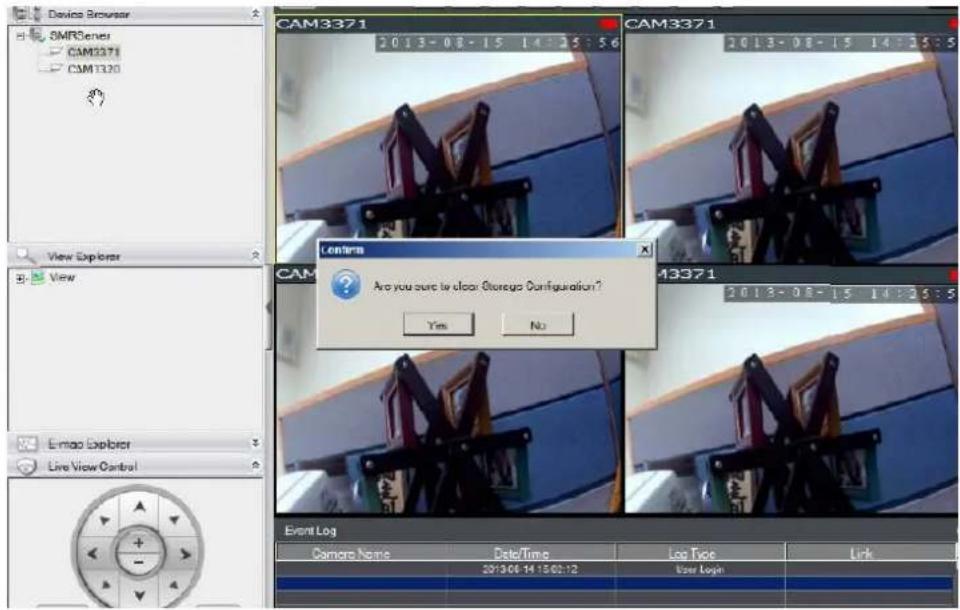
- Click Yes to restart the SMR to activate the settings.
- Turn on the SMR to have it start working.
Chapter 6. Basic System Settings
6.1. Storage Management
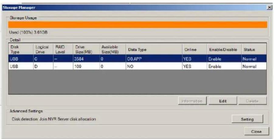
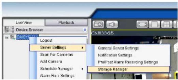
- To access the information about the drives configured in your Server, highlight and click the Storage Manager option under Server Settings.
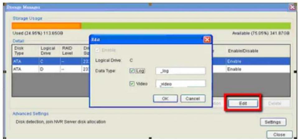
- All available Logical Drives, as well as their sizes, free space, and status will appear.
Click Edit to set the log and location for saving the video recordings.
(Step 3 and 4 are for the remote client of NVR2000/ SMR Series.)
3. Click the target drive first and then Settings.
In "Advanced Settings" dialogue, "General" tab, click Check.
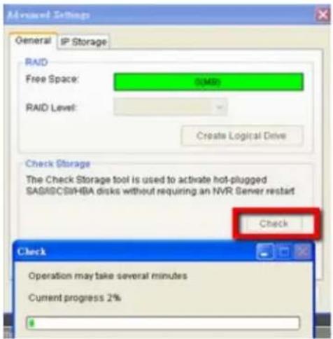
4. Choose the RAID level, and then click Create Logical Drive to create the RAID configuration.
Note: Storage Manager can also be accessed by clicking Server > General Tasks > Storage or Server Entry > Common Tasks > Common Server Tasks > Storage in the VMS Console.
6.2. Adding Cameras to the Server
Cameras can be added to the Server in two ways: via an automatic scan or by manually inputting the camera information.
6.2.1. Automatic Scan for Cameras
To begin an automatic scan for cameras:
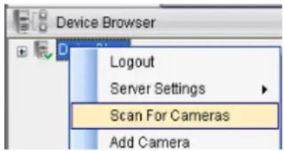
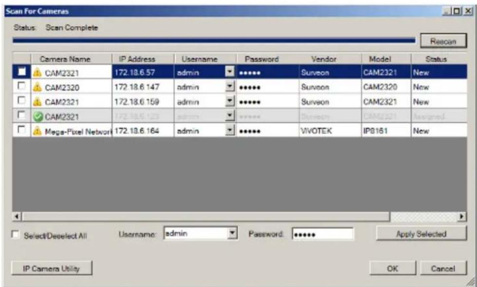
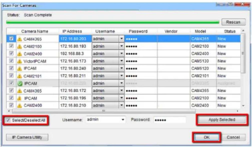
- Right-click the Server entry and select Scan for Cameras. The system will respond by beginning an automatic scan. Once the scan is complete, the cameras that can be added to the Server will be displayed. Information available for each camera will include:
Name - The default camera name (Make/ Model)
Status - The camera will display New if it has not been added to this Server, otherwise it will display Assigned.
IP Address
MAC Address
Vendor - Including ACTI, ASONI, AVTECH, AXIS, Arecont, Sosch, Brickcom, DyNACOLOR, D_Link, Dahua, EDIMAXHIKVISION, EverFocus, HIKVISION, IQinVision, Lilin, Eessoa, Mobotix, ONVIF, Panasonic, SIMON, SONY, Samsung, Surveon, VIVOTEK, and General.
Model
- To add a camera to the system, check the box by the camera entry. You may also check the Select All box at the bottom of the window to select all the cameras found.
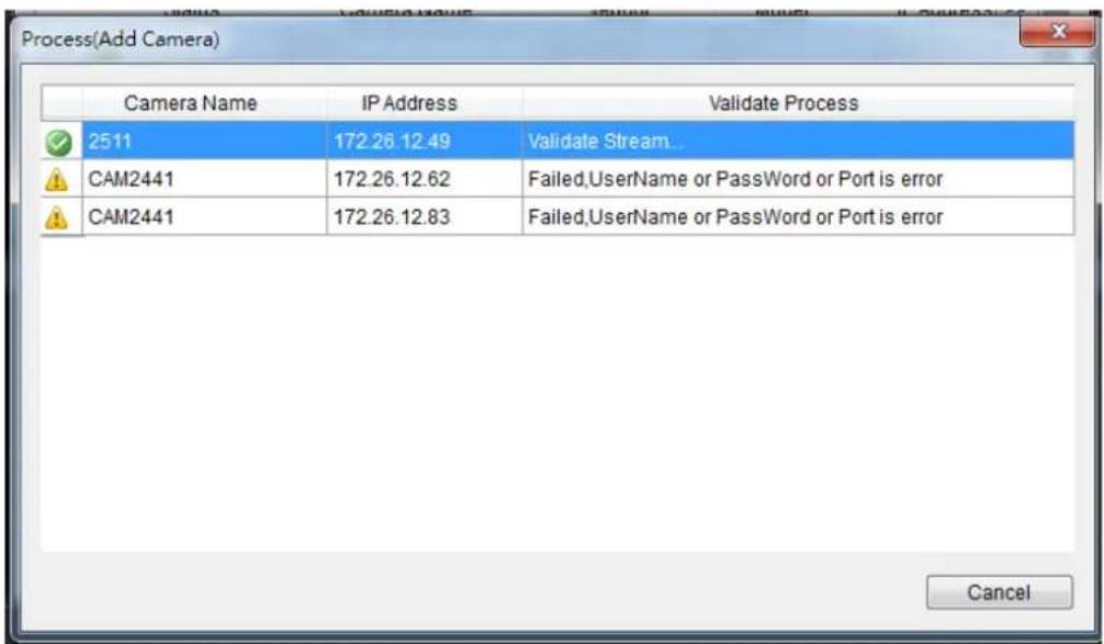
Enter the username and password, and press Apply Selected. Click OK to add the selected cameras to the Server.
The following windows will prompt for validation.
- (Optionally) Double-click any camera entry to bring up the camera detail page. From this page you may change the following information:

IP Address - Changing this value will affect connectivity.
- Camera Port - The web access port, default is 80.
Stream Port - Default is 6002.
Vendor - Changing this value will affect connectivity.
■ Model – Changing this value will affect connectivity.
- User Name – This value is not always required.
- Password - This value is not always required.
- Camera Name – It is recommended you change this value if you have more than one camera of this make/ model.
■ Camera Description
- Camera Icon - You can also import your own icon by clicking on the Browse button and choosing an icon file. Valid icon files include JPEG, GIF, PNG, BMP and ICON files.
Finally, you can access the web interface for the camera by clicking on the Go to Web Interface button. Click OK to save your changes, or Cancel to exit without saving.
- (Optionally) You may access the IP Utility for camera configurations of by clicking the IP Camera Utility button.
- Click OK to add the selected cameras to the Server.
Note: Automatic Scan for Cameras can also be accessed by clicking Camera List
General Tasks > Scan for Cameras or Server Entry > Common Tasks
Common Server Tasks > Scan for Cameras in the VMS Console.
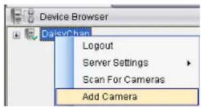
6.2.2. Manually Adding Cameras
To manually add a camera to the Server:
- Right-click the Server entry and select Add Camera.
- In the camera window fill out the following information:

IP Address
- Camera Port - This value will automatically populate with the default value for the Vendor and Model selected.
Vendor - Including ACTI, ASONI, AVTECH, AXIS, Arecont, Sosch, Brickcom, DyNACOLOR, D_Link, Dahua, EDIMAXHIKVISION, EverFocus, HIKVISION, IQinVision, Lilin, Eessoa, Mobotix, ONVIF, Panasonic, SIMON, SONY, Samsung, Surveon, VIVOTEK, and General.
■ Model - when “General” is selected, “RTP over TCP” and “RTP over UDP” can be further defined.
Stream Port - This value will automatically populate with the default value for the Vendor and Model selected.
- User Name – This value is not always required.
- Password - This value is not always required.
- Camera Name – It is recommended you change this value if you have more than one camera of this make/ model.
■ Camera Description - URI for Stream: when “General” is selected, “URI for Stream 1” can be further defined.
For example:
For a Surveon IP camera, type
RTSP://
For an AXIS IP camera, type
RTSP://
For a HIKVISION IP camera, type
RTSP://username:password@
- Camera Icon – You can also import your own icon by clicking on the Browse button and choosing an icon file. Valid icon files include JPEG, GIF, PNG, BMP and ICON files.
- Finally, once basic camera information is filled in, you may access the web interface for the camera by clicking on the Go to Web Interface button. Click OK to add the camera.
Note: Cameras can also be added manually by clicking Camera List > General Tasks > Add Camera in the VMS Console.
6.3. Setting Recording Schedule
A global Schedule applies to all cameras, while individual schedules are for each camera. Individual schedules take precedence over global schedules.
6.3.1. Weekly Scheduling
- Right-Click the VMS entry and choose Schedule Manager > Global Settings or Individual Schedule to bring up the Weekly Schedule popup.
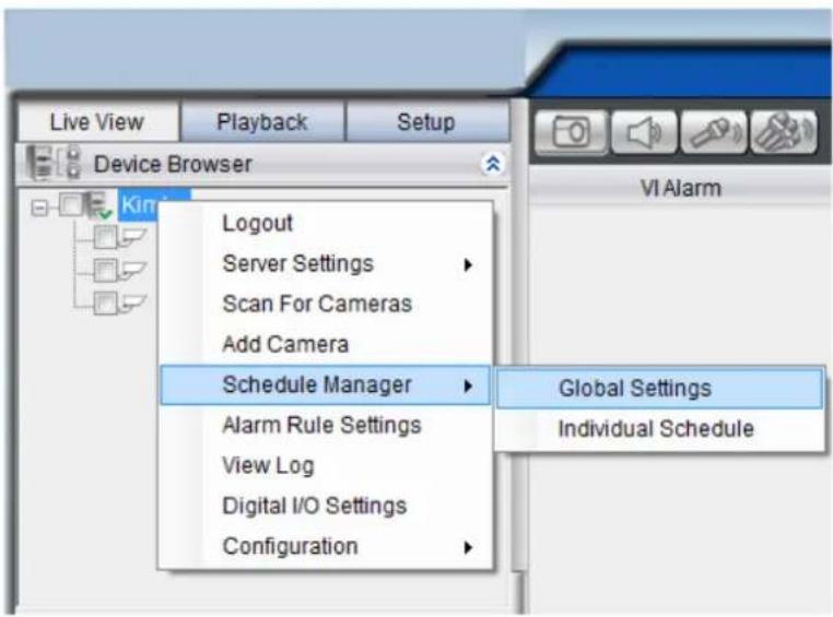
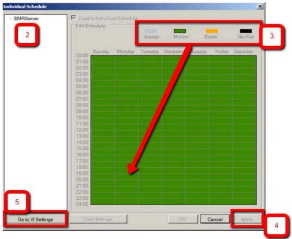
- If setting individual schedule and more than one camera is configured, choose the camera you wish to set from the list.
- The schedule grid corresponds to every hour in the week. Click on one of the four recording methods and then click on the grid area to "paint in" the method for the corresponding hour.
-
Click the Apply button to apply the schedule and OK to exit the dialog.
-
(Optional) You may go to the VI setting panel by clicking Go to VI Settings.
6.3.2. Daily Scheduling
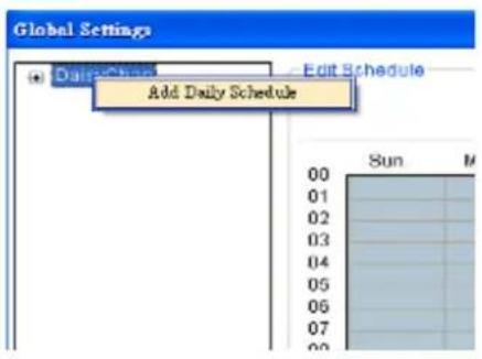
- Right Click the server entry and choose Add Daily Schedule.
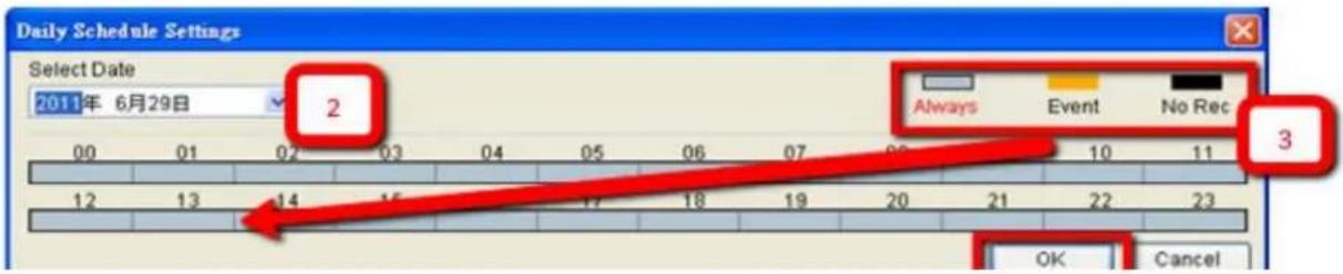
- Click the Select Date selection box and choose the date that you want to schedule.
-
Click on one of the methods and then click on the grid area to "paint in" the method for the corresponding hour.
-
Click OK to apply the changes.
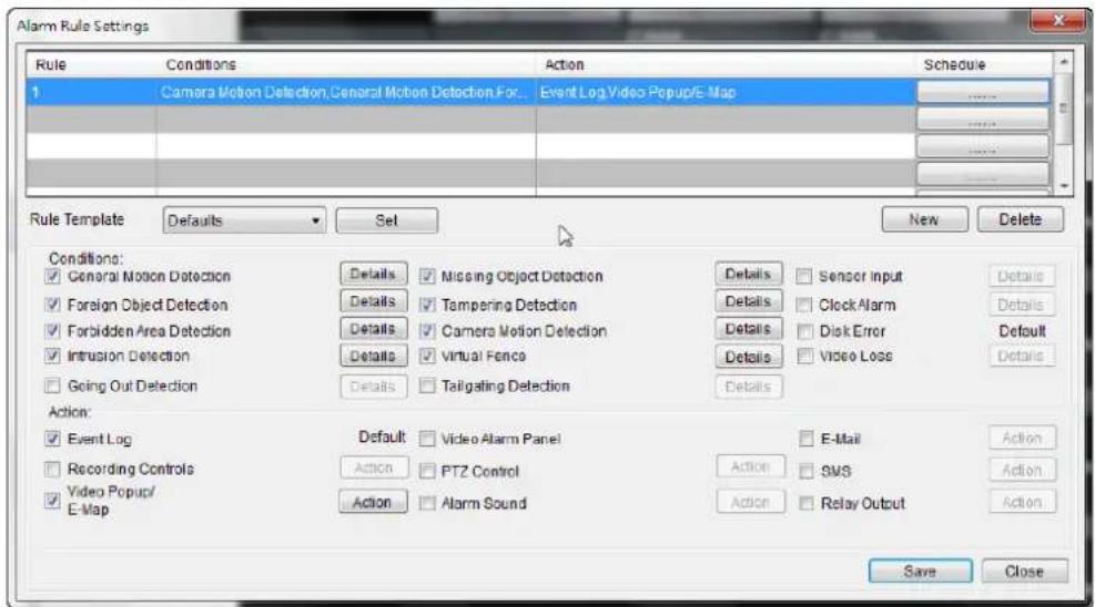
6.4. Adding Alarm Rules
Alarm rules can be created using the following elements:
- Rule: A short description. For example, “east-fence intrusion detection” or “front entrance access control.”
- Condition: Specifies triggering conditions such as Motion/Video loss/Sensor input/Clock Alarm, etc.
• Action: Specifies the action to take when the alarm is triggered. -
Schedule: Allows the user to schedule the application of specific Alarm rules. This is useful in cases such as applying rules to non-office hours.
-
Right-click the NVR entry and select the Alarm Rule Settings option under VMS node.
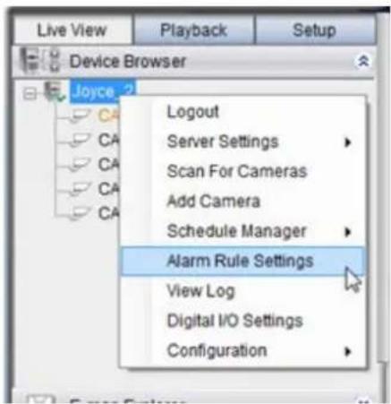
- Click the New button.
- Enter name for the new rule and click OK to create the rule.
- Choose conditions for the Alarm. Detailed settings can be changed by clicking Details.
- Select actions for the alarm. Detailed settings for actions can be set by clicking Action.
- Click the.....button in the alarm field to set up a schedule for the rule. Default scheduling is record always on.
- Click the Save button to save the rule.
6.5. Setting up Live View
An important part of monitoring your surveillance network is to have the right views so that you will have the optimum viewing angle to discern a situation.
The default view setting is 3x3.
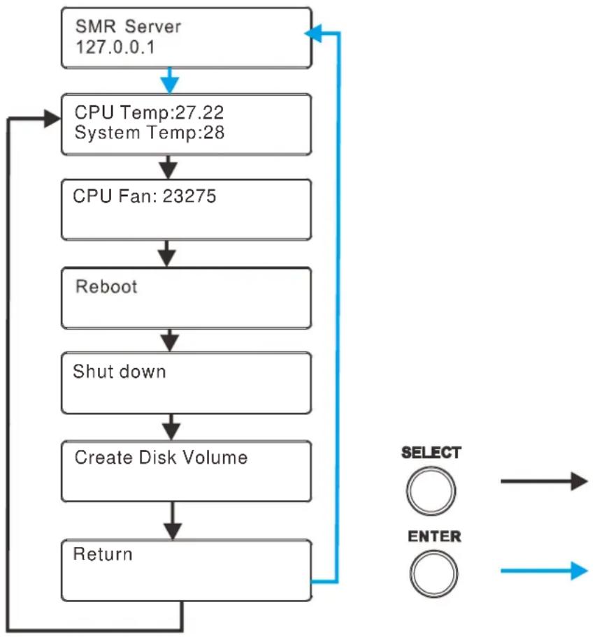
6.6. Using the LCD Menu in SMR Desktop Systems
The SMR 5000/8000 series come with a LCD screen that provides users with basic system statuses. There are 6 screen messages and selections: CPU and System Temperature, CPU fan Speed, Reboot, Shut Down, Create Disk Volume and Return. Users can enter these menus by pressing “Enter Button” first.
flowchart
graph TD
    A["SMR Server 127.0.0.1"] --> B["CPU Temp:27.22\nSystem Temp:28"]
    B --> C["CPU Fan: 23275"]
    C --> D["Reboot"]
    D --> E["Shut down"]
    E --> F["Create Disk Volume"]
    F --> G["Return"]
    G --> H["SELECT ○"]
    G --> I["ENTER ○"]
    H --> J["->"]
    I --> K["->"]
6.6.1. Checking the System Status
CPU and System Temperature/ CPU Fan Speed can be seen by pressing “Select Button” once/twice.
6.6.2. Rebooting/Shutting Down SMR
Users can enter the reboot/shut down menu by pressing “Select Button” twice or thrice, and then press “Enter Button” to restart/shut down the system.
Note: The function of “Create Disk Volume” menu is reserved.
Chapter 7. Live View
Live viewing is a crucial part of any surveillance system. Having the right view can be the crucial difference between catching an event as it happens and missing it altogether. VMS provides powerful tools to manage the viewing experience to help ensure that monitoring personnel are always on top of any event.
7.1. Live View Window Overview
The live view window is split into 14 distinct parts:
- Live View / Playback Selection Tabs - Allows users to choose live view and playback mode.
- Device Browser - Lists the Servers in the domain.
- View Explorer - Lists the views that are configured on this client.
- E-Map Explorer - Lists the E-maps available on this Server.
- Live View Control - Interface for interacting with PTZ-enabled cameras.
- Arrows for open up or close in the image panel and the VI Alarm panel.
-
VI Alarm -Area for alarm notification and instant playback.
-
Window Toolbar - Lock the window, minimize the window, or leave the system.
- View/Account Information - This area contains general information. Arrow button containing Server configuration options. Question mark indicates Help File. Logout button for a quick logout.
- Button Area - This area contains the buttons to change views, enter full screen mode, capture photos, send audio files to the chosen / all cameras and other useful functions.
 | Snapshot |
 | Volume control |
 | Talk to the chosen camera |
 | Broadcast to all the cameras |
 | Full screen mode |
 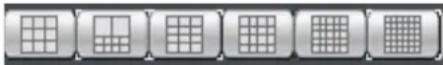 | Viewing screen modes |
 | Auto page flip between pages |
 | Reset all the settings, including page auto-flipping and different screen divisions |
-
Main View Area - This area contains the actual video feed(s).
-
Event Log Window - Close or send to another window for a better view of the Event Log.
-
Event Log - This area contains alarm and event information.
-
Version - Shows the current VMS version.
7.1.1. Resizing and Minimizing Windows
Minimizing Controls
The Device Browser, View Explorer, E-Map Explorer, Live View Controls, and Event Log can all be minimized by clicking on the arrow buttons on the top-right corner of their screens.
Hiding and Showing the Explorer Area
The entire left panel (containing the Live View/Playback Selection Tabs, Device Browser, View Explorer, E-Map Explorer, and Live View Controls) can be hidden by clicking on the arrow on the left of the Live View Control.
7.2. View Setup
7.2.1. Types of Views
The VMS/ NVR Server supports viewing of up to 32 cameras in a single view, with views of up to 36 cameras.
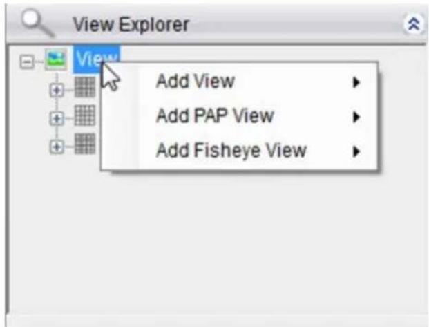
Note: SMR2000/ 5000 series supports views of up to 16 cameras.
Views with more subdivisions are more useful for giving an overview of an area, while ones with fewer subdivisions give better details. Multiple views can also be displayed in sequence or in separate windows for managing more than 16 cameras.
7.2.2. Adding a View
An important part of monitoring your surveillance network is to have the right views so that you will have the optimum viewing angle to discern a situation. To add a customized view to the VMS client:
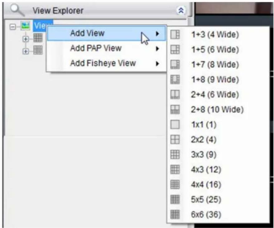
- Right click on Views in the View Explorer window, and choose the Add View option, the software will respond by listing available screen division types.
- Choose the type of view that you wish to add by clicking on the view. The software responds by placing a blank template in the main viewing window that has been subdivided into individual frames according to the view selected. The empty frames will display the message No camera.
- From the Device Browser window, you can click and drag the entries for individual cameras into the separate frames. The camera output will be displayed in the frame. Cameras in the view do not have to all be from the same server.
Dragging a camera into a frame that already has a camera assigned to it will cause the frame to be reassigned to the new camera. You can also drag the same camera into multiple frames or leave frames blank, although this is not suggested.
The View Explorer will be updated as you add cameras to your view. The root will list the camera numbers that have been added to the view starting from the top left frame and going from left to right and top to bottom.
Note: Depending on your connection and computer speed, it may take a moment for the image to refresh after dragging the camera into the view window. During this time the frame may still display No Camera or Failed to connect. If this problem persists, however, there may be a problem with your connection or hardware.
7.2.3. Add PAP View
PAP (Picture and Picture) View allows you to select multiple regions from one image to zoom.
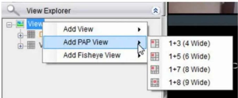
- Right-click the View entry in the View Explorer window. This will bring up an options popup.
- Select "Add PAP View" and then select the desired window number. 1 indicates the main original image and the number behind "+" means the numbers of the zoomed areas that you are about to create. For example, 1+8 means 1 main original image + 8 zoomed areas.
- Drag the set value from the View Explorer to the main image window.
- Drag the desired camera from the Device Browser to the main image window. Images from the camera you dragged will appear on the main image window.
- Move your mouse to select one window from the zoomed windows on the right. From the main image window use your mouse to drag out an area you'd like to zoom for the selected zoomed window. Zoomed images will appear on the zoomed windows.
- Repeat Step 5 to create more zoomed areas; 8 zoomed areas can be created when you set the PAP view to 1+8.
- Move the cursor to the box of the unwanted region and left click to see the options, Clear Region (clear 1 selected region)/ Clear All (clear every created region).
7.2.4. Add Fisheye View
Viewing angles are crucial for fisheye cameras to capture images and different installation method can affect the viewing angles. Fisheye viewing is supported in VMS.
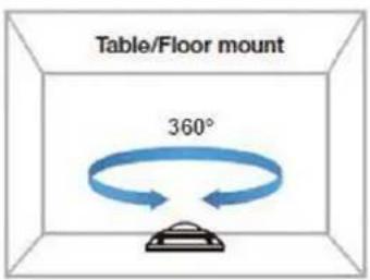
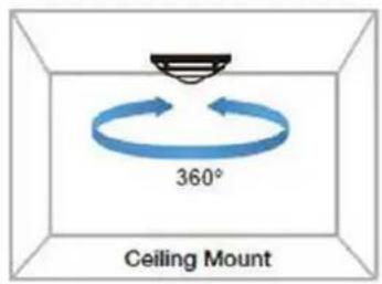
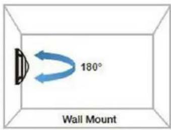
-
Right-click the View entry in the View Explorer window. This will bring up an options popup.
-
Select "Add Fisheye View" and then "1x1(1)".
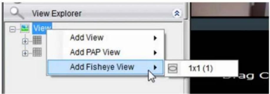
-
Drag the desired camera from the Device Browser to the main window. Images from the camera you dragged will appear on the main image window.
-
Select according to the way your fisheye is installed to have a best viewing result, Ceiling Mount, Table/Floor Mount or Wall Mount.
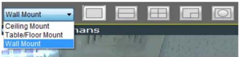
- The distorted hemispherical image of the fisheye camera can be converted into a conventional rectilinear projection, a split-
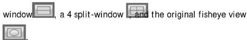
7.2.5. Renaming a View
To perform this function:
- Right-click the view entry in the View Explorer window. This will bring up an options popup.
- Highlight and click the Rename option.
- Enter a new name for the server and press enter to save the name.
7.2.6. Deleting a View
As views become superfluous or unused, it is desirable to delete a view. To perform this function:
- Right-click the view entry in the View Explorer window. This will bring up an options popup.
- Highlight and click the Delete option. The system will respond with a confirmation screen.
- Click the Yes button to delete the view.
7.2.7. Sending View to a New Window
In multi-monitor setups, you may send views to a separate window which can then be dragged to other screens. To do this:
- Right-click the view entry in the View Explorer window. This will bring up an options popup.
- Highlight and click the Send View To > Floating Window option. The system will respond by placing the view in a separate floating window. This window can be dragged to a separate screen, maximized, or closed.
7.2.8. Switching Between Views
To switch between saved views, simply click and drag the view entry from the View Explorer window into the main view window. Note that the current view is always indicated in Bold lettering in the View Explorer window.
7.2.9. Switching Between Different Screen Divisions
Creating and Using New Screen Divisions
When a view is created, it has a default screen division setting, however when using the view, it may be useful to change the number of screen divisions. This does not create a different view, but divides the existing view into a new set of divisions.

natural_image
Row of grayscale icons representing a grid, pie, and grid layout (no text or symbols)To perform this function within the view, simply click the button corresponding to the view that you want to use. The buttons are located in the area above the main view window.
After you have clicked on the desired view, the original number of cameras will be split into separate pages in the new view. For example, an original view consisting of 16 cameras would display the cameras on 2 pages of 8 frames, clicking on the 4 division button would display the 16 cameras in 4 pages of 4 frames each.
Screen Division Page Use
The page number is displayed to the right of the view buttons. Clicking on the arrow button to the right of the page number or clicking on the current screen partition button will scroll through the pages in order. Clicking on the arrow button to the left of the page number will scroll through the pages in reverse order.
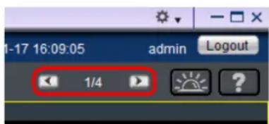
Auto-flipping Pages
When multiple pages of screen divisions exist, you may choose to automatically flip between the pages by clicking on the SPOT button. Clicking the button again will end the automatic flip function.

Configuring Page Dwell Time
Right-clicking the SPOT button will bring up a field to configure the amount of time each page will be displayed when automatically flipping pages. Enter the dwell time in seconds and click OK to change this value.
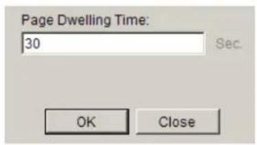
Exiting Different Screen Divisions
There are two methods to return to your original un-paginated view. You may either drag the original view into the main view area, or click the Home button in the button area. This will reset all the settings, including page auto-flipping and different screen divisions.

7.3. Functionality Within Views
Right clicking an active window will cause a function list to appear. These are settings and functions that can be changed within the live-view window.
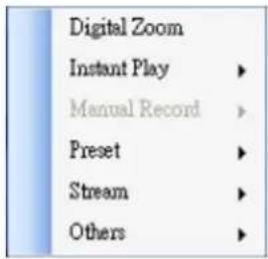
7.3.1. Digital Zoom
Digital zoom increases the view size without increasing resolution. The digital zoom function can be used within any panel (even in full screen mode) with the following steps:
- Right-click the panel that zoom is required on, and select Digital Zoom to activate the function. A picture-in-picture showing the whole screen framed by a yellow box will appear.
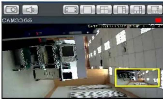
-
Click the corners of the box and drag to resize it over the area of interest. The main picture will show the digitally-zoomed output, while the picture and picture will display the entire view.
-
Alternatively, you may use the mouse scroll to zoom into the center of the image. Scrolling forward will zoom in, scrolling backward will zoom out.
7.3.2. Instant Playback
The instant playback function gives users the ability to instantly playback up to 45 minutes of video. Right-click the panel that playback is required on, and select Instant Play > [Time Length] to activate the function. A popup will open with the desired playback. Time lengths available are dependent on, and will not exceed the pre-alarm recording time set in Pre/Post Alarm Recording Settings.
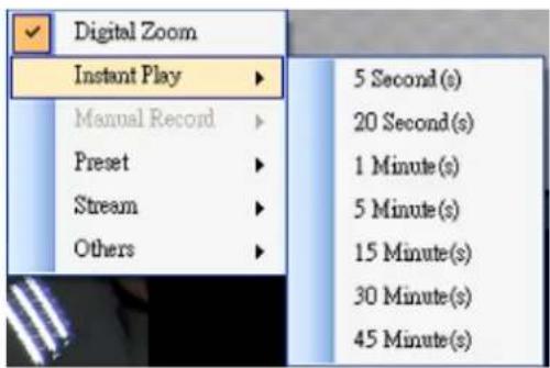
Playback can be displayed in 3 modes, Real Time 📁, Frame By Frame , and Just Key Frame ⭐. The default setting is in Real Time Mode, clicking on the button 📁 to change modes.
"Real Time" can be further defined to play in the speeds of 8x, 4x, 2x, 1x, 1/2x, 1/4x, and 1/8x.
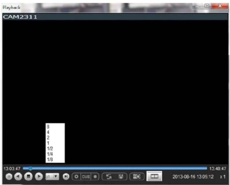

"Frame By Frame" can be further defined to play in intervals from 1 to
- Right click on the "Frame By Frame Mode" button to set the interval.
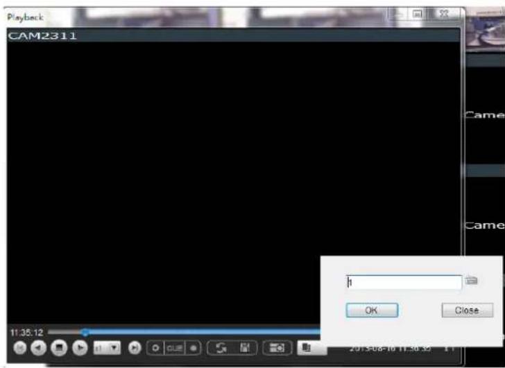

"Just Key Frame" can be further defined to play in intervals from 1 to
- Right click on the "Just Key Frame Mode" button to set the interval.
The following table explains the buttons:
 | Starts video playback. |
 | Reverses video playback. |
 | Stops video playback. |
 | Jumps to the next segment. |
 | Jumps to the previous segment. |
 | Clears the cue-in and cue-out markers. |
 | Set Cue-In marker for clip start |
 | Set Cue-Out marker for clip end |
 | Loop, continuous playback within Cue-In & Cue-Out |
 | Enable / Disenable loop. Loop to continuous playback within Cue-In & Cue-Out. |
 | Saves video clips/ Exports selected clips. |
 | Snapshot |
 | Real time mode |
 | Frame by frame mode |
 | Just key frame mode |
7.3.3. Manual Recording
When recording schedules are set, it may be necessary to manually record a video stream, even when the schedule does not specify for recording. In this case right-click the panel that recording is required on, and select Manual Record > [5, 10 or 30 minutes] to activate the function. The camera will record the stream for the amount of time specified.
7.3.4. Preset Pan
In cameras equipped with PTZ functionalities, presets set on the camera in the PTZ Preset Settings will be available. To access the presets, right-click on the panel containing the camera feed, and mouse-over Preset. The system will respond with a list of presets configured on the camera. Selecting a preset will pan the camera to the preset position.
7.3.5. Stream Selection
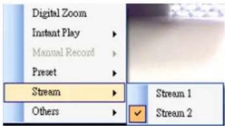
Video Streams can be selected by right-clicking the panel that playback is required on, and then select Stream > Stream1/Stream2.
7.3.6. Image Settings
Camera image settings can also be accessed by right-clicking the panel containing the camera video and selecting Others > Image Settings. This will pull up the camera image settings menu.
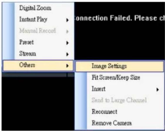
7.3.7. Video Ratio Adjustment
In most cases the video panel size will not match the size of the video feed exactly. By default the VMS will stretch or shrink the video to fit the screen, however you may also choose to preserve the original video ratio by right-clicking the screen and selecting Others > Keep Video Length-Width Ratio. To return to a stretched view, right-click the appropriate panel and choose Others > Resize to Fit Window.
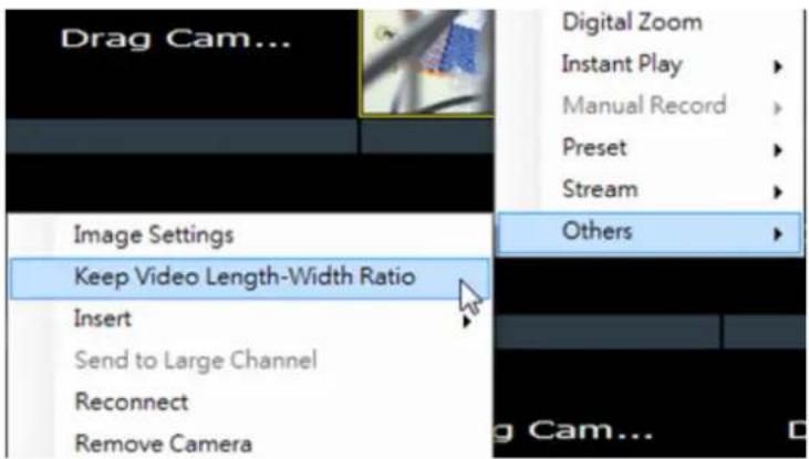
7.3.8. Inserting Overlays
The panel can be replaced with a user overlay.
Image Overlay
To overlay an image on top of a panel:
- Right-click the panel and choose Others > Insert > Image. The system will prompt you to choose an image file.
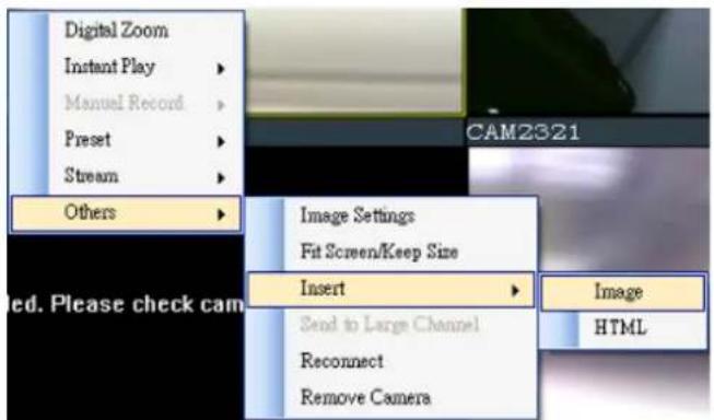
-
Choose an image file, valid image types are JPEG, BMP, TIF, PNG. Click Open to open the file.
-
The image will be displayed in the panel. Click the red X in the top-right corner to close the image.
HTML Overlay
The HTML overlay function allows simple integration of web applications in the VMS by replacing one or more panels of the screen with an active browsing window. To overlay an HTML form or website on top of a panel:
- Right-click the panel and choose Others > Insert > HTML.

- In the field, enter a URL or the path containing the HTML form. You may also choose to click Browse and choose an HTML file.
- The HTML or website will be displayed in the panel. Click the red X in the top-right corner to close the image.

7.3.9. Send to Large Channel
Views in smaller divisions can be switched to the larger division. To perform this action, right-click the panel corresponding to the camera and choose Others > Send to Large Channel.
7.3.10. Reconnect
In some cases it may be necessary to manually reset the connection to a camera. To perform this action, right-click the panel corresponding to the camera and choose Others > Reconnect.
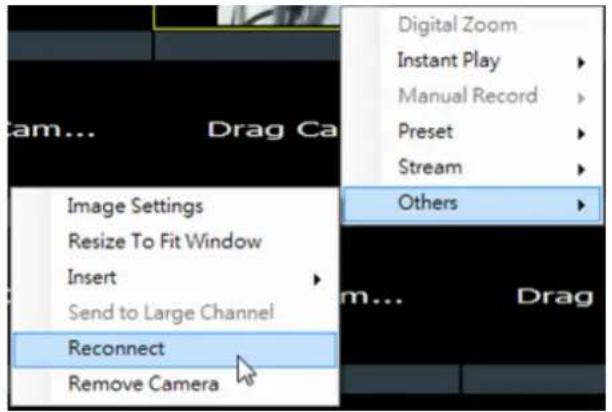
7.3.11. Remove the Camera
The Cameras can be removed by clicking Others > Remove Camera.
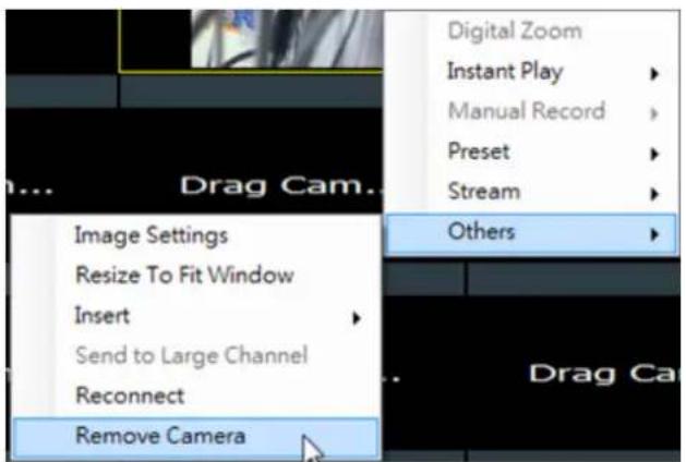
7.3.12. Onscreen PTZ Control
Cameras equipped with Pan-Tilt-Zoom functionality can be controlled directly within the VMS client software. These controls can be found within live views whenever the cursor comes closer to the image panel, the onscreen PTZ control will appear.

Pan and Tilt
The pan and tilt functionalities can be controlled with the directional pad.
Clicking the right or left arrow will pan the camera by one step in the direction clicked. Clicking the up or down arrow will tilt the camera by one step in the direction clicked. Clicking diagonal arrows will combine the pan and tilt action of the adjacent arrows.
Zoom
The zoom on a camera can be controlled with the + and - buttons located inside the direction pad. Pressing the + button will increase zoom distance by 1 step. Pressing the - button will decrease zoom distance by one step.
7.4. Full Screen View
7.4.1. Entering Full Screen View
From any view, you can switch to full screen mode by clicking on the full screen button located above the main viewing window. Optionally you may also choose to view a single frame in full screen mode by double clicking on the frame.
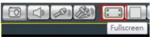
7.4.2. Exiting Full Screen Mode
To exit full screen mode, hit the ESC key on your keyboard.
7.5. E-Maps
7.5.1. Adding E-Maps
- Prepare layout drawings or a map of the area being surveyed.
- Right click on E-Map Configuration in the E-map Explorer window, Click Add under the E-map tab.
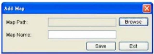
- Click the Browse button to open a windows dialog. Select your map and click the Open button. The drawing will be stored in the Server.
- Enter a name for the map in the Map Name field.
- Click Save. Once successfully added, an E-map node will appear.
Note: The E-Maps can also be edited by clicking Server > General Tasks > E-map or Server Entry > Common Tasks > Common Server Tasks > E-map in the VMS Console.
7.5.2. Adding Sub-Maps
Sub-maps can be used when separate areas within a large maps are complicated enough to have their own specific layout.
- Prepare layout drawings or a map of the area being surveyed.
- In the E-map configuration screen, under the E-map tab, right-click the node that you wish to add a sub-map to, and select Add > Sub-Map.
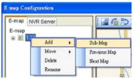
- Click the Browse button to open a windows dialog. Select your map and click the Open button. The drawing will be stored in the Server.
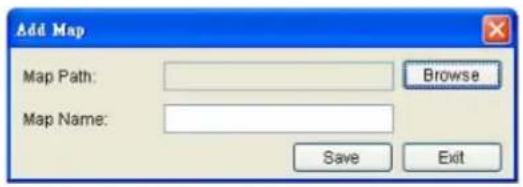
-
Enter a name for the map in the Map Name field.
-
Click Save. Once successfully added, an E-map node will appear as a sub-node on the tree panel. A link with the sub-map name will also be placed on the root map.
7.5.3. Adding Additional E-Maps
The typical E-map Add function will add new maps to the end of the list. You may choose to add a map before or after an existing map by:
-
Prepare layout drawings or a map of the area being surveyed.
-
In the E-map configuration screen, under the E-map tab, right-click the node which you want to add a map before or after. Choose Add > Previous Map to add a map before the selected map, or choose Add > Next Map to add a map after the selected map.
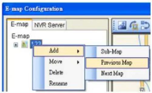
- Click the Browse button to open a windows dialog. Select your map and click the Open button. The drawing will be stored in the Server.
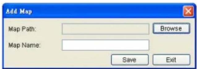
-
Enter a name for the map in the Map Name field.
-
Click Save. Once successfully added, an E-map node will appear as in the tree panel.
In the e-maps list, it is recommended to organize your e-maps in a logical order.
7.5.4. Changing E-Map Order
To re-order the e-maps you have added, right-click the node which you want to move. Choose Move > Previous Map to move the selected map up the list, or choose Move > Next Map to move the selected map down the list.
7.5.5. Renaming an E-Map
To rename an e-map you have added, right-click the node which you want to delete and choose Rename. Enter a new name for the map and press enter to save your changes.
7.5.6. Configuring an E-Map
- Select an E-map entry clicking it.
- Click the NVR Server tab to bring up a list of the cameras available for placement.
- Drag and drop cameras to anywhere on the layout drawing. The map may be moved by clicking and dragging the map, you may also zoom in and out using the buttons above the map display. If the map size is lower than 396x247, you'll be prompted to select Normal or Resize to fill Emap window. The default setting is Resize to fill Emap window.
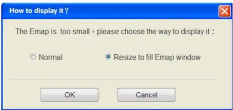
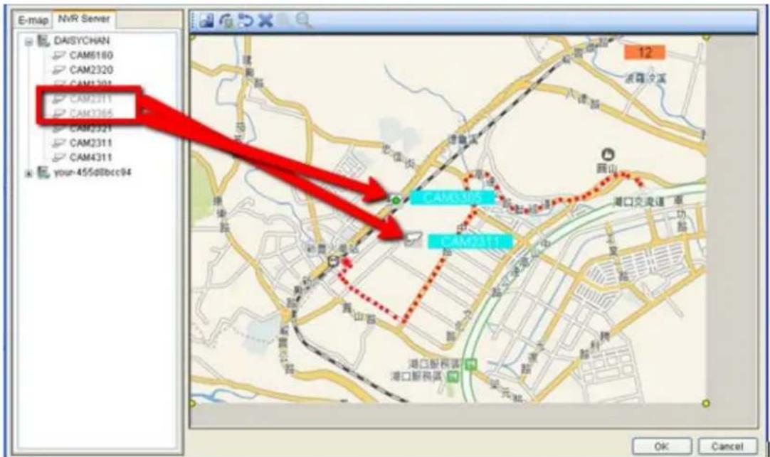
-
Once a camera icon is placed, it may be rotated by clicking one of the dotted corners of the camera icon.
-
You may save any time by clicking on the Save button located above the map display.
7.5.7. Deleting an E-Map
To delete an e-map you have added, right-click the node which you want to delete and choose Delete. This action will delete the node and any sub-nodes from the map list.
7.5.8. Using the E-Map
Once E-Maps have been configured on the system, you can pull up an E-Map by double clicking its entry in the E-Maps section of the Live View screen. This will open the E-Map in a floating window.
Double-clicking on any camera icon that has been placed on the map will bring a live view screen for this camera.
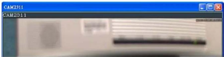
You can choose to do instant playback, snapshot capture and alarm management by right clicking on the live view screen.
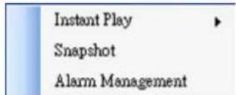
The camera icons that have been placed on the map will blink if there is an alarm associated with it. Double-click on any camera icon to bring up a live video feed in a popup window.
There are also a few buttons associated with this view:
Zoom Out: Located at the bottom mid-left. This button shrinks the background map display.
Zoom In: Located at the bottom mid-right. This button enlarges the background map display.
Arrows: Located on the top left. Use the arrow keys to move from map levels.
Up to 4 cameras can be popped up at the same time, when there's any alarm triggered. If there's a fifth alarm occurs, the VMS will close the oldest popup window and show the new popup.
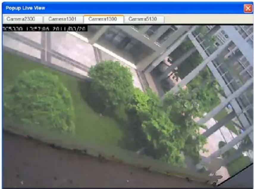
Chapter 8. Server Setup
This section deals with Server setup procedures.
8.1. Server Basic Functions
When you are logged into a domain, the Servers configured on the domain will appear in the Device Browser area. The icon by the Server shows the current connection state of the Server.
| Icon Meaning | |
 | The Server cannot be reached |
 | The Server can be reached, but the user is not logged in |
 | The user is logged in to the Server |
8.1.1. Logging into a Server
- Right-click the server entry in the Device Browser window to bring up the options popup.
- Highlight and click the Login option. As long as the credentials supplied at the beginning of the session are correct, you will be automatically logged in.
8.1.2. Logging out of a Server
- Right-click the server entry in the Device Browser window to bring up the options popup.
- Highlight and click the Logout option to bring up the logout dialog box.
- Press the Yes button to logout.
Note: Logging out of the domain server will cause the client to logout completely.
8.1.3. Renaming a Server
You must be connected to a server as an admin to rename it. To rename a Server:
- Right-click the server entry in the Device Browser window to bring up the options popup.
- Highlight and click the Configuration > Rename option.
- Type the new name in the box that appears.
8.1.4. Viewing Server and Client Information
- Right-click the server entry in the Device Browser window to bring up the options popup.
- Highlight and click the Configuration > About option to bring up the About dialog box.
- Click OK when finished viewing.
Note: The Server and Client information can also be viewed by clicking Others > Other Tasks > About in the VMS Console.
8.2. Server Settings
The following sections deal with Server settings that can be configured under the Server Settings menu.
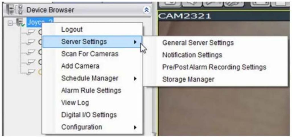
8.2.1. General Server Settings
Server general setup procedures involve configuring both storage and server time settings. To perform Server general setup:
Right-click the Server entry in the Device Browser, highlight and click the Server Settings > General Server Settings option. A tabbed window will appear providing the following configuration tabs: Storage Quota, Time Settings, Automatic Correction.
1. Storage Quota
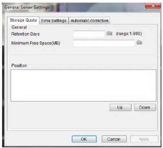
In the Minimum Free Space field, the Minimum space required for storage is shown. The storage will be last for 3 days. You may move the saving locations up and down the list using the Up and Down buttons, to change the storage priorities.
2. Time Settings
To set the server time click on the number you wish to change and enter a value. Click OK to preserve the setting. The default time is set according to the real-time clock on server.

3. Automatic Correction
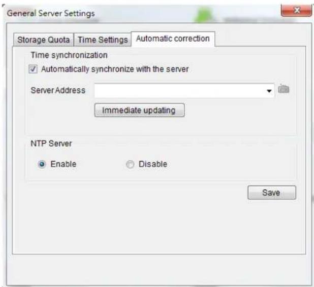
Time can be synchronized with a chosen server, typing the desired server IP address in the blank.
Select "Enable" to set your SMR/NVR device as your NTP Server and the camera time can be synchronized with your SMR/NVR device. Click OK to finish the configuration.
Note: General Server Settings can also be configured by clicking Server > General Tasks > General Server Settings in the VMS Console.
8.2.2. To perform Notification Setting
- Right-click the Server entry in the Device Browser highlight and click the Server Settings> Notification Setting option. A tabbed window will appear prompt providing the following configuration tabs: SMTP Server and SMS Settings. The window starts with the SMTP Server tab displayed.
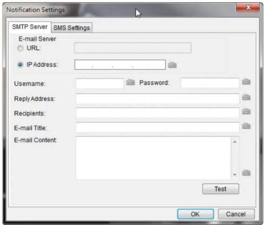
-
In the SMTP Server tab, under the E-mail Server heading, you may either enter the URL (such as smtp.abc.com) or IP address of the SMTP server that the Server will use to deliver E-mail notifications. The SMTP server configured here must support Unicode Transformation Format-8 (UTF-8) encoding.
-
Enter the user name for the Server email account in the Username field.
-
Enter the password for the Server email account in the Password field.
-
Enter a valid E-mail address in the Reply Address field. This address will be the default sender listed in E-mails sent from the Server.
-
Enter one or more E-mail addresses in the Recipients: field. These address(es) will receive notifications from the Server. Multiple addresses can be entered by separating individual addresses with semi-colons “;”.
-
Enter the subject of your notification E-mails, e.g., Server-xxxsite1notification in the E-Mail Title field.
-
Enter a short message in the large field to describe the Server or a surveillance network.
-
(Optional) Click Test to send a test message to the E-mail addresses listed.
-
Click the SMS Settings tab to continue.
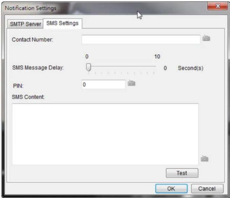
Note: Drivers for supported GSM/ GPRS modems have already been installed on the server. Currently, only the WaveCOM-M1206B is supported. Use COM1 on the Server to connect to a GSM modem.
-
In the Contact Number field, enter the phone numbers that will receive SMS notifications. Be sure to include the area code, e.g., “86”, in front of phone numbers. Use commas, “,” to separate individual phone numbers.
-
Use the slider bar to select a delay between the occurrence of an event and SMS message delivery.
-
(Optional) If a SIM PIN is required, enter the PIN code in the PIN field. Note that applying incorrect PIN code may disable your SIM card.
Note: To change the PIN code, remove the SIM card from your GSM modem. Use a cell phone to change the PIN code and then re-install SIM card into the GSM modem. Changing PIN codes is not recommended because a configuration failure may disable your SIM card.
- In the SMS Content field, type a simple description to include in the outgoing SMS messages
- (Optional) Click Test to send a test message to the phone numbers listed.
- Click the Apply button to apply the changes.
- Click the OK button to exit E-mail/ SMS settings.
Note: E-mail and SMS Settings can also be done by clicking Server > General Tasks > E-mail/SMS in the VMS Console.
8.2.3. Pre/Post Alarm Recording Settings
Video streams are constantly processed and cached in memory. The Server can trace back and preserve video/images from several minutes before and after the occurrence of an alarm.
To configure pre/post-alarm recording times, highlight and click the Pre/Post Alarm Recording Settings option under Server Settings. The following pop-up window will appear:
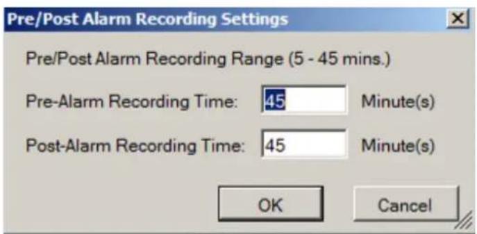
In each of the boxes enter values for the Pre and Post-Alarm Recording times from 5 to 45 minutes (default is 45 minutes). Click the OK button to finish the process.
Note: Pre/ Post Alarm Recording Settings can also be done by clicking Server > General Tasks > Pre/Post Alarm Recording Settings in the VMS Console.
8.2.4. Storage Management
- To access the information about the drives configured in your Server, highlight and click the Storage Manager option under Server Settings.
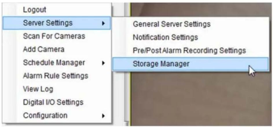
- All available Logical Drives, as well as their sizes, free space, and status will appear.
Click Edit to set the log and location for saving the video recordings.
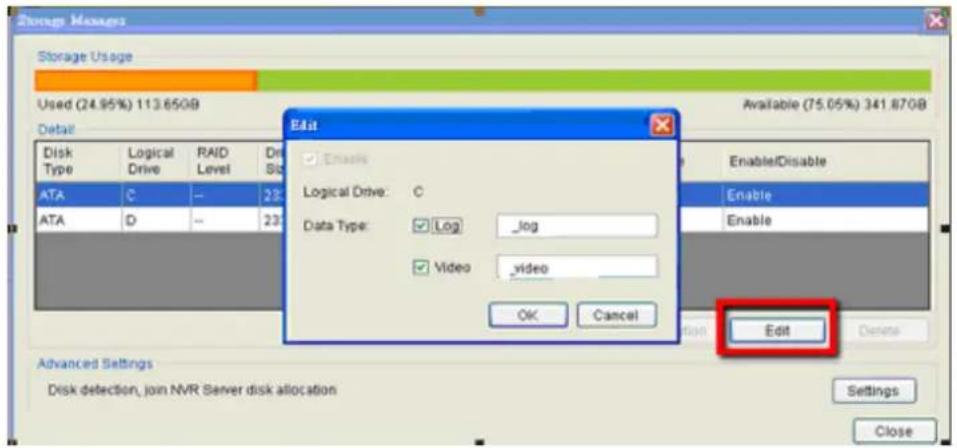
(Step 3 and 4 are for the remote client of NVR2000/ SMR Series.)
3. Click the target drive first and then Settings.
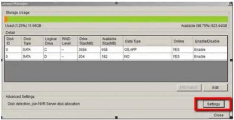
In "Advanced Settings" dialogue, "General" tab, click Check.
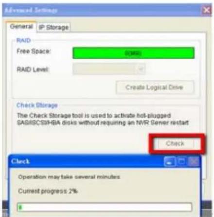
- Choose the RAID level, and then click Create Logical Drive to create the RAID configuration.
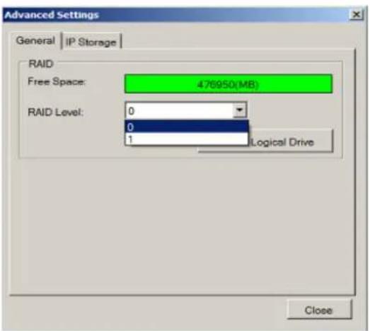
Note: Storage Manager can also be accessed by clicking Server > General Tasks > Storage or Server Entry > Common Tasks > Common Server Tasks > Storage in the VMS Console.
8.3. Scheduling Recording
There are two forms of scheduling available. A global schedule can be created to apply to an entire Server, while an individual schedule can be created for each camera on a Server. Schedules are further split into weekly and daily schedules. When scheduling conflicts occur, the daily schedule takes precedence over the weekly schedule.
8.3.1. Global Scheduling
Note: A global schedule can also be set by clicking Server > General Tasks > Global Schedule or Server Entry > Common Tasks > Common Server Tasks > Storage in the VMS Console.
Weekly Global Scheduling
To access the Global Scheduling tool right click the Server entry, then highlight and click the Schedule Manager > Global Settings option to bring up a popup containing a schedule grid corresponding to every hour of every day in the week. The schedule default is always recording, all the time. To change the global schedule:
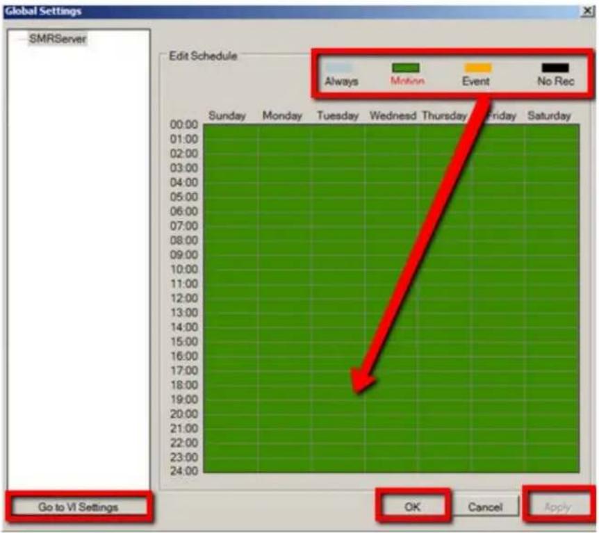
- Choose a recording method by clicking on one of the four methods: Always record or record on Event trigger. (You can also keep the default as Motion record.)
- Click on a table cell to "paint" the recording method. The color in the cell will change to match the selected recording method. Click and drag the cursor to paint large areas.
- When you are finished, click the Apply button to apply the schedule.
- (Optional) You may go to the VI setting panel by clicking Go to VI Settings.
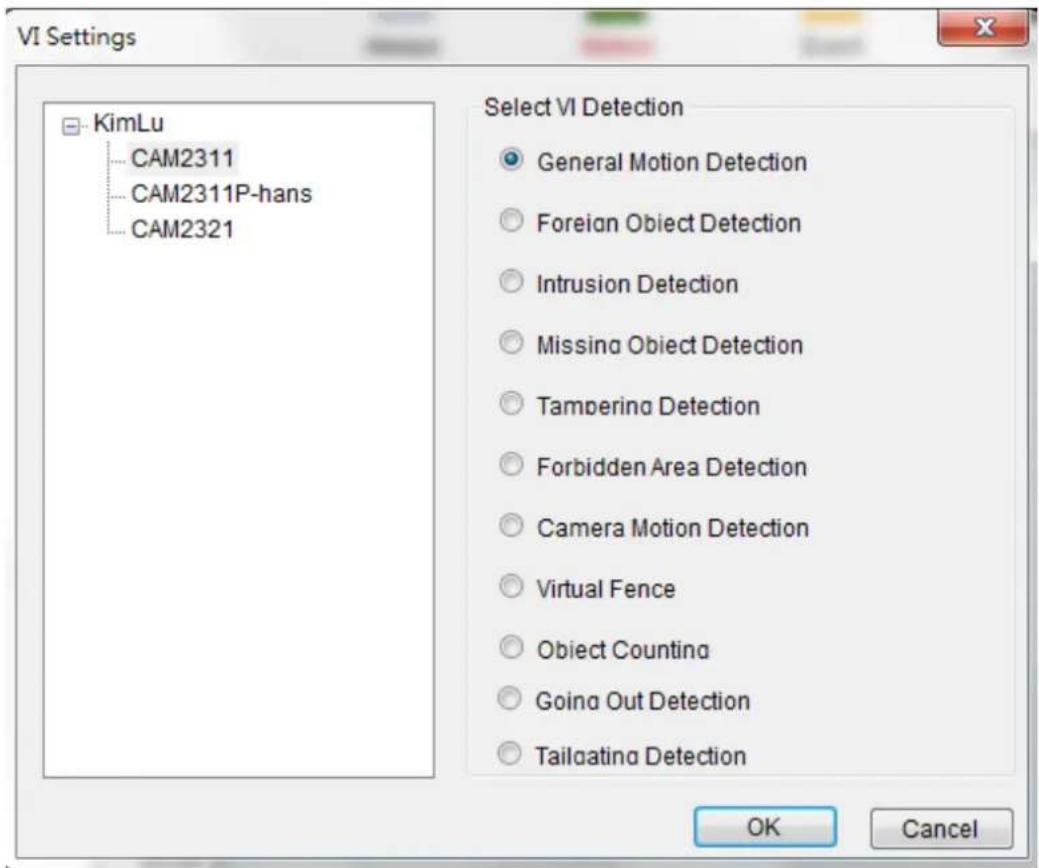
- Click OK to exit the menu.
Daily Global Scheduling
Adding a Daily Global Schedule
In addition to the weekly global schedule, a daily schedule can also be set for a certain day. To perform this action:
- Under Global Settings, right-click the server listing, and click on the Add Daily Schedule option to bring up the Global Daily Schedule Settings popup. This popup consists of 24 segments corresponding to the hours in the day.
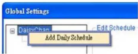
- Choose the date that you want to schedule.
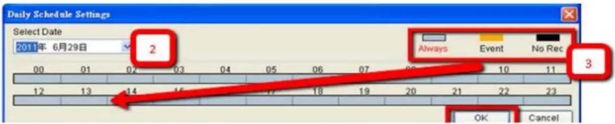
-
Choose a recording method by clicking on one of the three methods: Always record, record on Motion detection, or record on Event trigger.
-
Click on a table cell to "paint" the recording method. The color in the cell will change to match the selected recording method. Click and drag the cursor to paint large areas.
-
When you are finished, click the OK button to apply the schedule. The schedule will show up under the server entry in the Global Settings according to the date you have just set.
Deleting a Global Daily Schedule
To delete a global daily schedule, right-click the schedule entry and select Delete Schedule. Click the Yes button to confirm deletion.
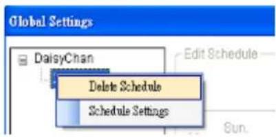
Editing a Global Daily Schedule
To edit a global daily schedule, right-click the schedule entry and select Schedule Settings.
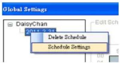
8.3.2. Individual Scheduling
Individual schedules, which take precedence over the global schedule, can be set for each camera.
Note: An individual schedule can also be set by clicking Server > General Tasks > Individual Schedule in the VMS Console.
Weekly Individual Scheduling
To access the individual scheduling tool right-click the server entry, then highlight and click Schedule Manager > Individual Schedule.
Schedule defaults are always recording, all the time. To create a schedule:
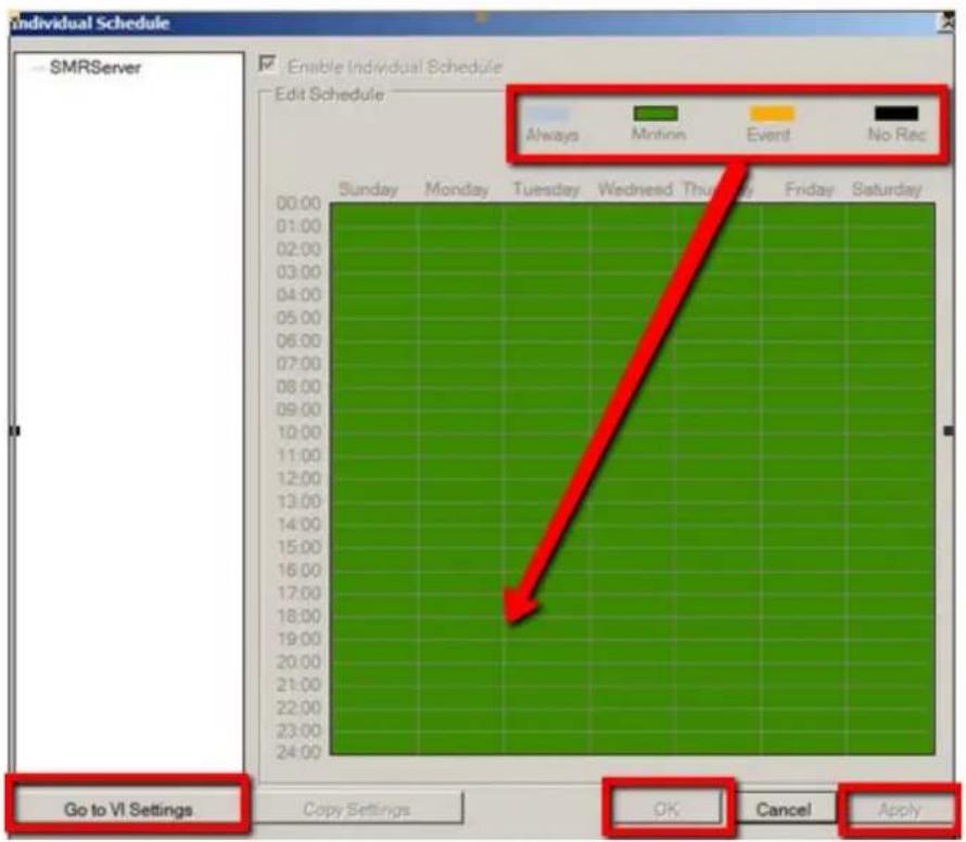
-
Select the camera which you want schedule.
-
Click the Enable Individual Schedule box to enable the schedule.
-
Choose a recording method by clicking on one of the four methods: Always record, record on Motion detection, or record on Event trigger. (You can also keep the default as Motion record.)
-
Click on a table cell to "paint" the recording method. The color in the cell will change to match the selected recording method. Click and drag the cursor to paint large areas.
-
When you are finished, click the Apply button to apply the schedule. Click OK to exit the menu.
- (Optional) You may go to the VI setting panel by clicking Go to VI Settings.
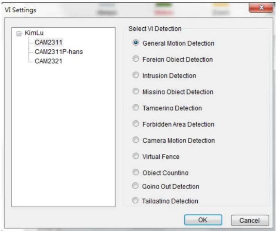
- Click OK to exit the menu.
Daily Individual Scheduling
Adding a Daily Individual Schedule
In addition to the weekly individual schedule, a daily schedule can also be set for a certain day. To perform this action:
- In Weekly Individual Schedule right-click the camera listing, and select Add Daily Schedule option to bring up the Individual Daily Schedule Settings popup. This popup consists of 24 segments corresponding to the hours in the day.
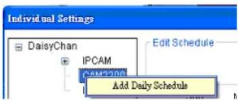
flowchart
graph TD
    A["DaisyChan"] --> B["IPCAM"]
    B --> C["Add Daily Schedule"]
    D["Edit Schedule"] --> C
- Choose the date that you want to schedule

- Choose a recording method by clicking on one of the three methods: Always record, record on Motion detection, or record on Event trigger.
- Click on a table cell to "paint" the recording method. The color in the cell will change to match the selected recording method. Click and drag the cursor to paint large areas.
- When you are finished, click the OK button to apply the schedule. The schedule will show up under the camera entry in the Individual Settings according to the date you have just set.
Deleting an Individual Daily Schedule
To delete an individual daily schedule, right-click the schedule entry and select Delete Daily Schedule. Click Yes to confirm deletion.
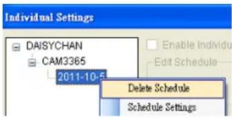
Editing an Individual Daily Schedule
To edit an individual daily schedule, right-click the schedule entry and select Schedule Settings.
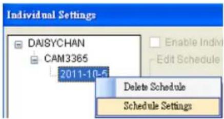
Chapter 9. Camera Setup
This section deals with Camera setup procedures. These options can be accessed by right-clicking the Camera entry in the Device Browser.
8.1. Adding Cameras
Cameras can be added to the Server in two ways, VIA and automatic scan, or by manually inputting the camera information.
9.1.1. Automatic Scan for Cameras
To begin an automatic scan for cameras:
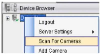
- Right-click the Server entry and select Scan for Cameras. The system will respond by beginning an automatic scan. Once the scan is complete, the cameras that can be added to the Server will be displayed. Information available for each camera will include:
Name - The default camera name (Make/ Model)
Status - The camera will display New if it has not been added to this Server, otherwise it will display Assigned.
IP Address
MAC Address
Vendor - Including ACTI, ASONI, AVTECH, AXIS, Arecont, Sosch, Brickcom, DyNACOLOR, D_Link, Dahua, EDIMAXHIKVISION, EverFocus, HIKVISION, IQinVision, Lilin, Eessoa, Mobotix, ONVIF, Panasonic, SIMON, SONY, Samsung, Surveon, VIVOTEK, and General.
■ Model - when “General” is selected, “RTP over TCP” and “RTP over UDP” can be further defined.
- To add a camera to the system, check the box by the camera entry. You may also check the Select All box at the bottom of the window to select all the cameras found.
Enter the username and password, and press Apply Selected. Click OK to add the selected cameras to the Server.
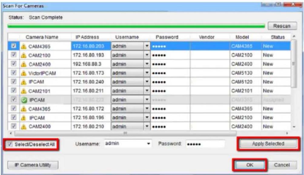
The following windows will prompt for validation.

- (Optionally) Double-click any camera entry to bring up the camera detail page. From this page you may change the following information:
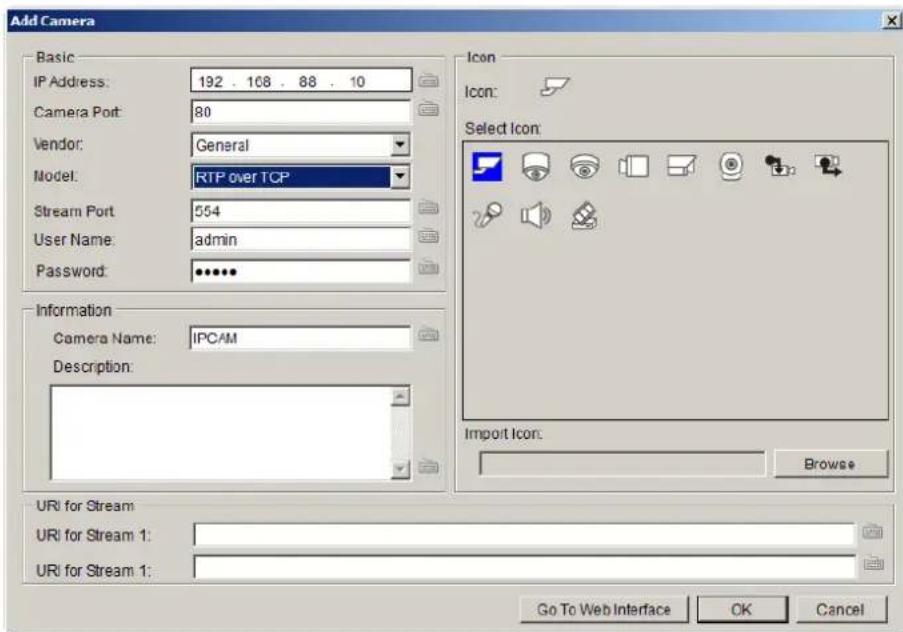
IP Address – Changing this value will affect connectivity.
- Camera Port - The web access port, default is 80.
Stream Port - Default is 6002
Vendor - Changing this value will affect connectivity.
■ Model - Changing this value will affect connectivity.
- User Name - This value is not always required.
- Password - This value is not always required.
- Camera Name – It is recommended you change this value if you have more than one camera of this make/ model.
■ Camera Description
- Camera Icon - You can also import your own icon by clicking on the Browse button and choosing an icon file. Valid icon files include JPEG, GIF, PNG, BMP and ICON files.
Finally, you can access the web interface for the camera by clicking on the Go to Web Interface button. Click OK to save your changes, or Cancel to exit without saving.
- (Optionally) You may access the IP Utility for camera configurations by clicking the IP Camera Utility button.
- Click OK to add the selected cameras to the Server.
Note: Automatic Scan for Cameras can also be accessed by clicking Camera List > General Tasks > Scan for Cameras or Server Entry > Common Tasks > Common Server Tasks > Scan for Cameras in the VMS Console.
9.1.2. Manually Adding Cameras
To manually add a camera to the Server:
- Right-click the Server entry and select Add Camera.
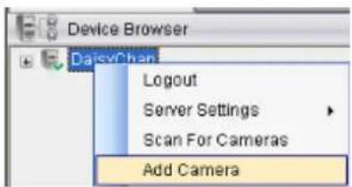
- In the camera window fill out the following information:
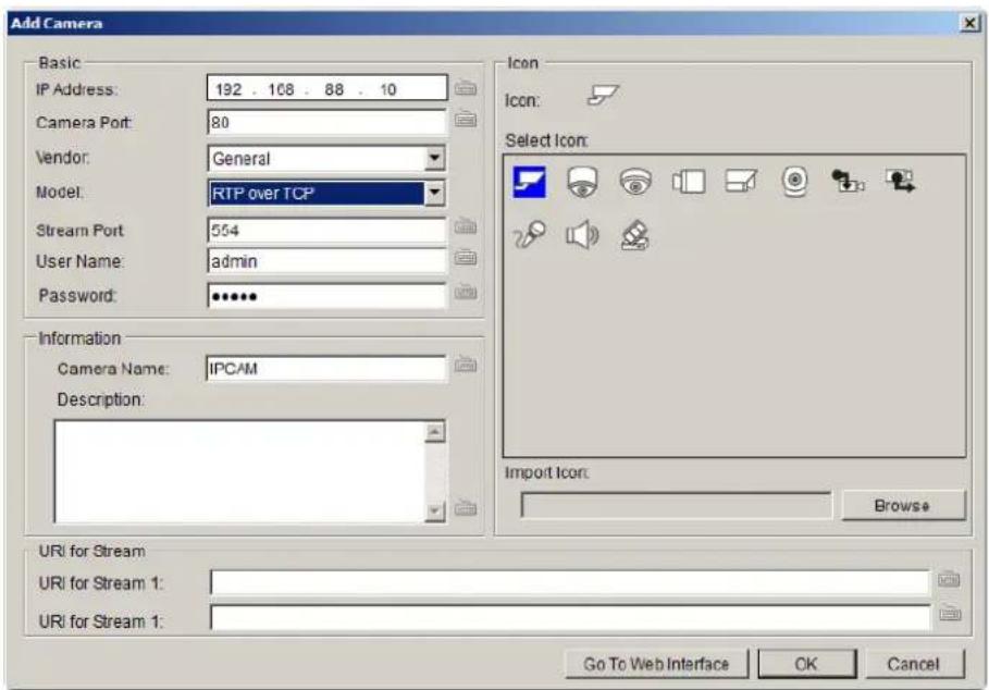
IP Address
- Camera Port - This value will automatically populate with the default value for the Vendor and Model selected.
Vendor - Including ACTI, ASONI, AVTECH, AXIS, Arecont, Sosch, Brickcom, DyNACOLOR, D_Link, Dahua, EDIMAXHIKVISION, EverFocus, HIKVISION, IQinVision, Lilin, Eessoa, Mobotix, ONVIF, Panasonic, SIMON, SONY, Samsung, Surveon, VIVOTEK, and General.
■ Model - when “General” is selected, “RTP over TCP” and “RTP over UDP” can be further defined.
Stream Port - This value will automatically populate with the default value for the Vendor and Model selected.
- User Name – This value is not always required.
- Password – This value is not always required.
- Camera Name - It is recommended you change this value if you have more than one camera of this make/ model.
■ Camera Description
- Camera Icon - You can also import your own icon by clicking on the Browse button and choosing an icon file. Valid icon files include JPEG, GIF, PNG, BMP and ICON files.
- Finally, once basic camera information is filled in, you may access the web interface for the camera by clicking on the Go to Web Interface button. Click OK to add the camera.
Note: Cameras can also be added manually by clicking Camera List > General Tasks > Add Camera in the VMS Console.
9.1.3. Deleting a Camera
- Right-click the camera entry you wish to remove in the Device Browser window to bring up the options popup.
- Highlight and click the Delete Camera option. The system will respond with a warning dialog.
- Click Yes to delete the camera from the Server.
Note: Cameras can also be deleted by clicking Camera List > General Tasks > Delete Camera in the VMS Console.
9.1.4. Initializing a Camera
Initializing the camera resets the camera so that it will correspond to the settings on the Server. To perform this operation:
- Right-click the camera entry in the Device Browser window to bring up the options popup.
- Highlight and click the Initialize option. The system will respond with a warning dialog.
- Click Yes to reset the camera.
Note: Camera initialization can also be done by clicking Camera List > Camera Settings > Initialize in the VMS Console.
8.2. Camera General Settings
8.2.1. Logging into a Camera
It is important to note that you must be logged into the camera before you can change any settings. To login to the camera:
- Right-click the camera entry and select Camera Settings > Edit Camera.
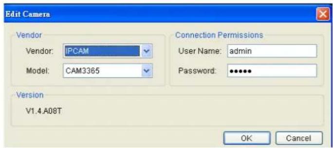
- In the Connection Permissions section, enter a valid username in the User Name field and password in the Password field.
Note: The system will not perform an active check on the username and password. Setting an incorrect username or password may affect camera connectivity and configurability.
- Click OK to login.
8.2.2. Changing the Camera Model and Vendor
In certain situations it may be necessary to change the Vendor or Model information for the camera. To perform this operation:
- Right-click the camera entry and select Camera Settings > Edit Camera.
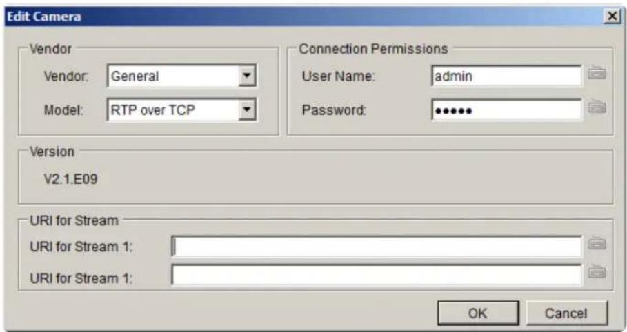
- Select the new Vendor and Model from the respective drop-downs.
When there's no suitable option for your device, you can select "General" from the Vendor dropdown list and defined if it's a "RTP over TCP" or a "RTP over UDP" from the Model dropdown list. Once set, define URI for Stream 1.
See the reference below for further setting.
For an AXIS IP camera,
key in "RTSP://
For a HIKVISION IP camera,
key in "RTSP://username:password@
For a Surveon IP camera,
key in "RTSP://
Note: Setting an incorrect vendor or model may affect camera connectivity.
- Click OK to save your changes.
Note: Edit Camera can also be accessed by clicking Camera List > Camera Settings > Edit Camera in the VMS Console.
8.2.3. General Settings
Camera general settings include network connectivity settings, as well as basic camera name, description and icon settings.
- Right-click the camera entry and select Camera Settings > Camera General Settings.
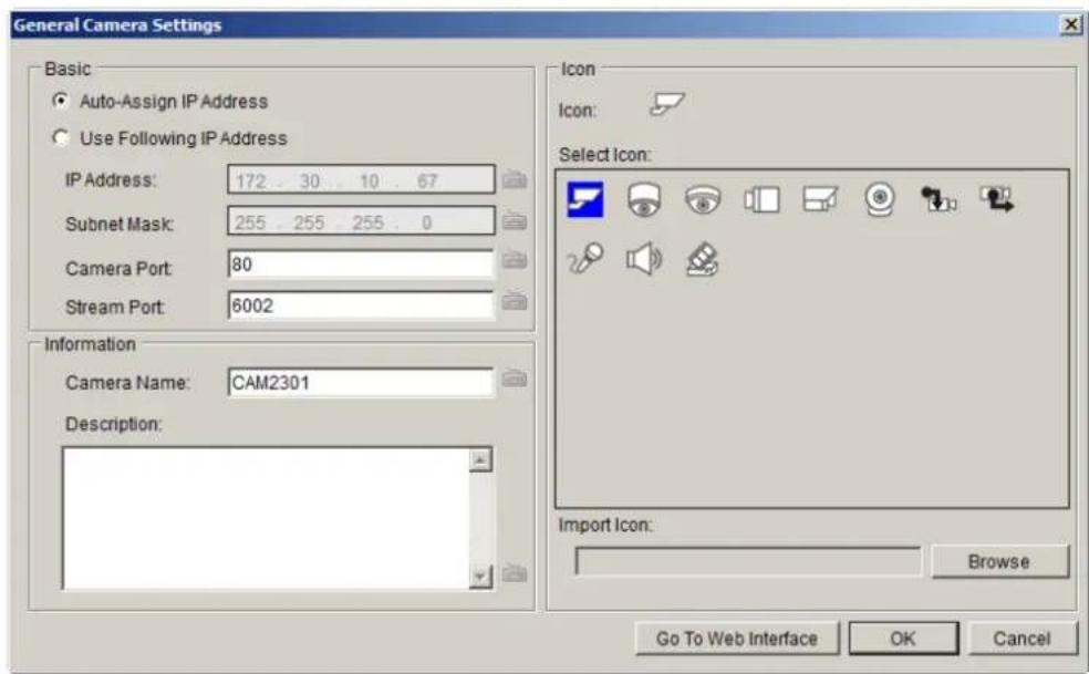
- There are two ways to specify the IP address for the camera.
If you wish to automatically assign an IP address to the camera using DHCP services, select the Auto-assign IP Address option.
If you wish to assign a fixed IP, select Fixed IP Address, and provide an IP address for the camera in the IP Address field. The Subnet Mask will be shown together with the IP address.
-
You may continue by editing any of the following options:
-
Camera Port - This value will automatically populate with the default value for the Vendor and Model selected.
Stream Port - This value will automatically populate with the default value for the Vendor and Model selected. - Camera Name – It is recommended you change this value if you have more than one camera of this make/ model.
■ Camera Description
- Camera Icon - You can also import your own icon by clicking on the Browse button and choosing an icon file. Valid icon files include JPEG, GIF, PNG, BMP and ICON files.
- Click OK to save your changes.
Note: Camera General Settings can also be configured by clicking Camera List > Camera Settings > Camera General Settings in the VMS Console.
8.2.4. OSD Settings
On cameras with OSD capabilities, these capabilities can be configured within the server. To configure the information for the on-screen display:
- Right-click the camera entry and select Camera Settings > OSD Settings to bring up the OSD settings menu.
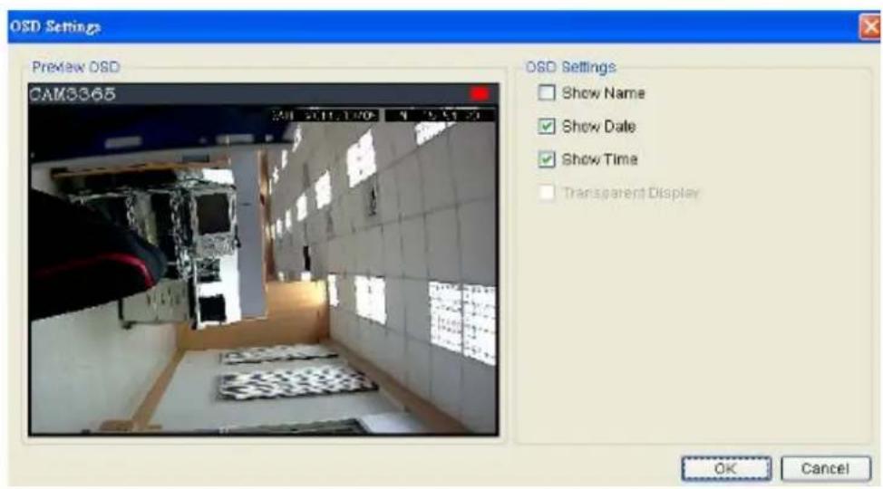
- Choose any of the following options:
Show Name – Displays the camera name. If this item is selected, you will also have the option of entering another name to display.
■ Show Date - Displays the camera date.
■ Show Time - Displays the camera time.
- Transparent Display – When this option is chosen, the camera will not black-out the lettering background.
- Click OK to save your changes.
Note: OSD Settings can also be configured by clicking Camera List > Camera Settings > OSD Settings in the VMS Console.
8.2.5. Privacy Mask Settings
The camera can be configured to display useful information on the top bar. To configure the information for the on-screen display:
- Right-click the camera entry and select Camera Settings > Mask Settings to bring up the privacy mask settings menu.
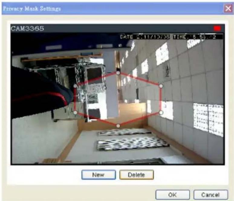
- Click the New button to create a new privacy mask overlay, denoted by a red border.
- Click and drag the overlay to move the overlay around the screen. Click and drag one of the six white dots on the red border to resize and reshape the overlay. If multiple windows are present, the window being edited will have a red border.
- Repeat these steps to create up to three windows. Click OK to save the privacy mask.
The masked areas will be shown in black on the live view screen after the mask is saved.
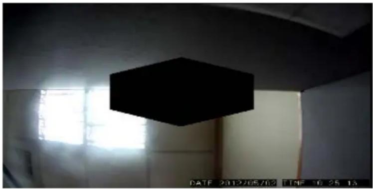
natural_image
Interior view of a room with a black hexagonal ceiling light and a window, no visible text or symbols.Note: (1) The masked areas can be unmasked during a video export with an administrative password. For more details refer to the section on video export. (2) Privacy Mask Settings can also be configured by clicking Camera List > Camera Settings > Mask Settings in the VMS Console.
8.3. Camera Image and Quality Settings
8.3.1. Camera Image Settings
To configure camera image settings:
- Right-click the camera entry in the Device Browser, then click Image Adjustments > Image Settings.
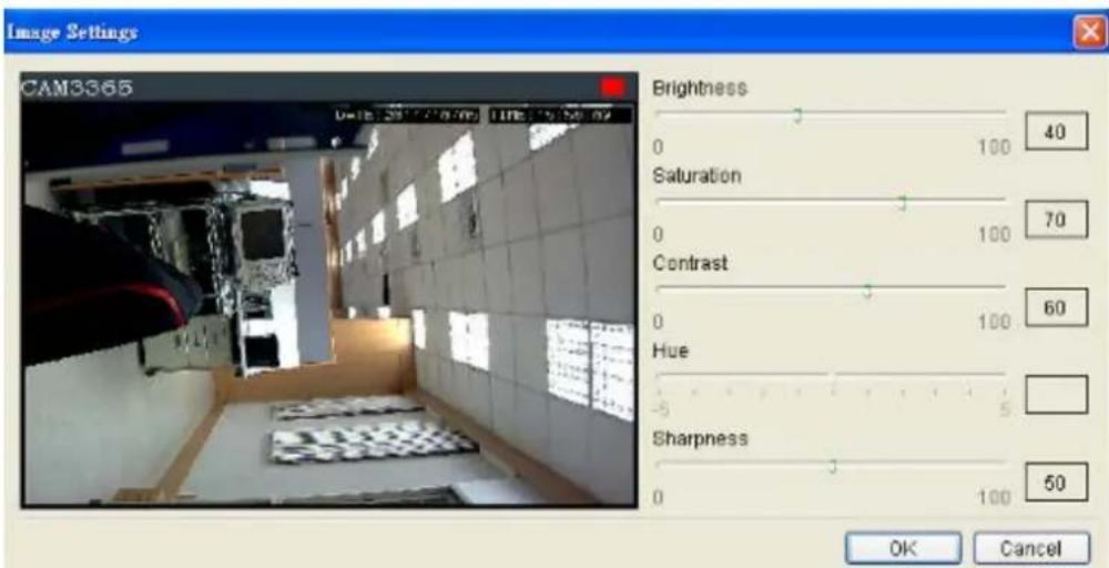
Note: You must be logged into the camera before changing settings or else the operation will fail.
-
Adjust the following sliders to change the camera image:
-
Brightness - The overall lighting level of the image. This value can be used to boost or reduce the apparent lighting of the image.
Saturation - The overall color intensity of the image. This value can be used to boost or reduce overall color intensity. - Contrast - The lighting difference between dark and light areas of the image. This value can be used to boost or reduce apparent differences in lighting.
- Hue - The color cast of the image. This value can be used to compensate for colored lighting or other color casting.
-
Sharpness - The edge contrast of the image. This value can be used to make the picture appear clearer.
-
Click OK to save your changes.
Note: Camera Image Settings can also be configured by clicking Camera List > Camera Settings > Image Settings in the VMS Console.
8.3.2. Advanced Video Settings
- Right-click the camera entry in the Device Browser, then click Image Adjustments > Advanced Video Settings.
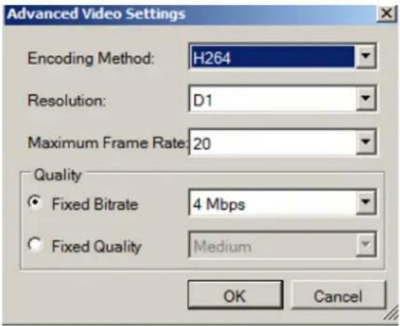
Note: You must be logged into the camera before changing settings or else the operation will fail.
- Select a video encoding method from the Encoding Method drop-down. Encoding methods will vary by camera type, but common ones include:
MJPEG
MPEG-4
H264
- Select a video resolution from the Resolution drop-down. Supported resolutions will vary by camera.
Select the maximum video frame rate from the Maximum Frame Rate drop-down.
-
From the Quality section, choose one of the following:
-
Fixed Bitrate - The camera image quality will be adjusted within a fixed bitrate selected in the dropdown. Dropdown values will vary by camera.
- Fixed Quality - The camera bitrate will be adjusted to meet the quality selected in the dropdown. Dropdown values will vary by camera.
Note: Video Quality Settings can also be configured by clicking Camera List > Camera Settings > Advanced Video Settings in the VMS Console.
8.4. PTZ Settings
In cameras equipped with any combination of pan, tilt or zoom (PTZ) functionality, these settings are used to configure the PTZ functions.
8.4.1. PTZ Settings
The PTZ settings deal with the software PTZ control panel. These settings adjust how much the camera will pan, tilt, zoom, and focus with each control panel input.
Note: You must be logged into the camera before changing settings or else the operation will fail.
- Right-click the camera entry in the Device Browser, and click PTZ Settings > PTZ Settings.
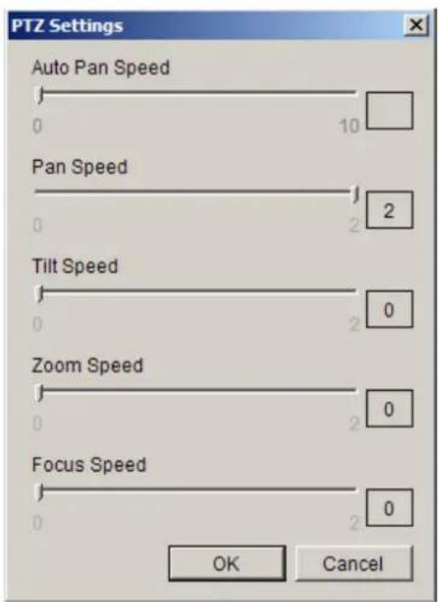
- Adjust the following sliders to increase and decrease the following speeds: (The higher the value, the higher the speed) Unsupported features on specific cameras will be grayed out.
■ Auto Pan Speed – The speed which the camera will pan between the mechanical stops when the Auto Pan function is activated.
Pan Speed - The distance the camera will pan to each side.
- Tilt Speed - The distance the camera will tilt up and down.
■ Zoom Speed - The distance the camera will zoom near or far.
■ Focus Speed - The amount the camera will focus forward or backward.
Note: PTZ Settings can also be configured by clicking Camera List > Camera Settings > PTZ Settings in the VMS Console.
8.4.2. PTZ Preset Settings
Certain preset pan/tilt/zoom values can be saved in order to move the camera quickly to a point of interest. To configure camera PTZ preset settings, right-click the camera entry, then highlight and click PTZ Settings > Preset Settings option.
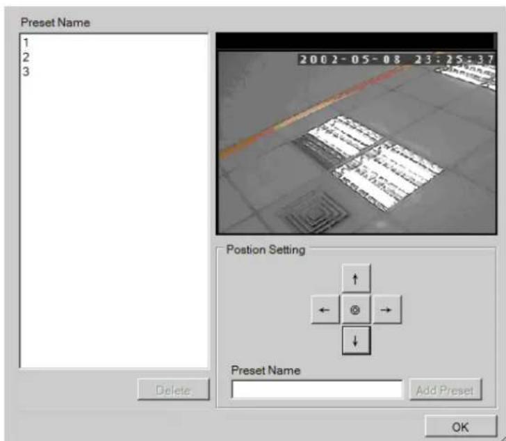
The popup will display the camera output, as well as a Position Setting pad.
Note: You must be logged into the camera before changing settings or else the operation will fail.
Adding a Preset
-
Use the directional pad to move the camera view. Use the center "home" button to return the camera to the default zeroed view.
-
Once the camera reaches the point where a preset is desired, type a name into the Preset Point Name field.
-
Click the Add a preset point to add the preset to the list. Click OK exit the menu, or you may continue to add/delete additional presets.
Deleting a Preset
To delete a preset, simpy highlight the preset and click the Delete button. Click the Yes button to confirm deletion. Click OK exit the menu, or you may continue to add/ delete additional presets.
Note: PTZ Preset Settings can also be configured by clicking Camera List > Camera Settings > Preset Settings in the VMS Console.
8.4.3. PTZ Patrol Settings
In cameras with PTZ functionality, one camera can be used to survey a large area. This can be done automatically using the patrol functionality. This function basically moves the camera between preset points in a fixed pattern. To configure camera patrol settings:
- Right-click the camera entry in the Device Browser, then highlight and click the PTZ Settings > Patrol Settings.
![Patrol Settings Preset 1 2 3 Options 1 □ Activate Duration 1 Stop ○ Stop Time 0 Patrol Range[1 - 360]Min ○ Continuous Patrol << OK Cancel](/content/2026/06/1178915/images/47ec9633e0a6556f6eca4261947104d0dad6eb8af69c199fb4d19274b155c5dd.jpg)
Note: You must be logged into the camera before changing settings or else the operation will fail.
- On the right side of the popup there will be a list of preset points that are defined for the camera. Use the >> button to add the points to the
patrol list in the order that they are to be viewed. Points can also be removed by highlighting them and clicking on the << button.
- Select the length of time the camera will dwell at each preset point before continuing from the Dwelling Time (Sec) dropdown.
-
Select one of the following:
-
Stop Time - The camera will stop the number of minutes specified in the box between patrol sessions.
-
Never Stop – The camera will not stop between patrol sessions.
-
Click the Active button to activate the patrol list.
-
Click the OK button to save the patrol list and exit the popup.
Note: PTZ Patrol Settings can also be configured by clicking Camera List > Camera Settings > Patrol Settings in the VMS Console.
8.5. PTZ Controls
Cameras equipped with Pan-Tilt-Zoom functionality can be controlled directly within the VMS client software. These controls can be found in the Live View Control window within the live view screen.
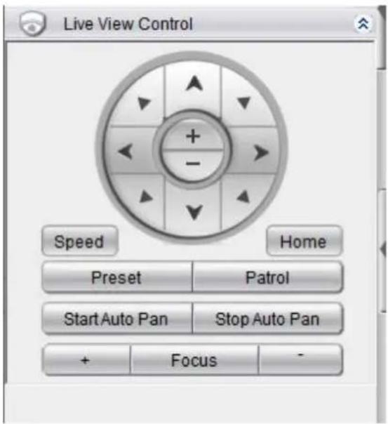
Note: (1) The camera to be controlled must be selected by highlighting it (clicking its output window) in the main view window. (2) Joystick can also be used for PTZ control. Please refer to Server Setup > General Tasks > Joysticks for more details.
8.5.1. Directional Pad
Pan and Tilt
The pan and tilt functionalities can be controlled with the directional pad.
Clicking the right or left arrow will pan the camera by one step in the direction clicked. Clicking the up or down arrow will tilt the camera by one step in the direction clicked. Clicking diagonal arrows will combine the pan and tilt action of the adjacent arrows. Clicking on the Home icon, located at the center of the pad, will re-center the camera.
Zoom
The zoom on a camera can be controlled with the + and - buttons located inside the direction pad. Pressing the + button will increase zoom distance by 1 step. Pressing the - button will decrease zoom distance by one step.
8.5.2. Functional Buttons
Speed
Auto Pan Speed - The speed which the camera will pan between the mechanical stops when the Auto Pan function is activated.
Pan Speed - The distance the camera will pan to each side.
Tilt Speed - The distance the camera will tilt up and down.
Zoom Speed - The distance the camera will zoom near or far.
Focus Speed - The amount the camera will focus forward or backward.
Home
One position can be set as the Home position. Click on Home button to go to the Home position. Clicking on the Home button will re-center the camera.
Preset
The camera may have preconfigured viewpoints, or presets configured. To switch to one of these presets, click the Preset button and select the preset.
Adding a Preset
You must first be logged into the camera to add a preset. To add a preset using the PTZ controls:
-
Pan, tilt, zoom, and focus to the desired preset position.
-
Click the Preset button and select Add Preset.
-
Type a name into the Preset Name field. Click OK to add the preset.
Deleting a Preset
You must first be logged into the camera. To delete a preset using the PTZ controls:
Click the Preset button and select Delete Preset Point.
Click the Yes button to confirm deletion.
Patrol
In cameras with PTZ functionality, one camera can be used to survey a large area. This can be done automatically using the patrol functionality.
Start Auto Pan
The camera will pan between the mechanical stops when the Auto Pan function is activated.
Stop Auto Pan
The camera will stop auto pan between the mechanical stops when the Auto Pan function is inactivated.
Focus
The focus on a camera can be controlled with the + and - buttons located beside the Focus box. Pressing the + button will increase focus distance by 1 step. Pressing the - button will decrease focus distance by one step.
Chapter 10. Alarms and Events
Alarm handling in the VMS is divided into 4 distinct phases:
- Condition: The condition is the triggering event for the alarm such as Motion/Video loss/Sensor Input/Clock Alarm, etc.
- Action: Specifies steps and actions that can be undertaken when an alarm is triggered.
- Rule: An alarm rule combines conditions with corresponding actions.
- Schedule: Allows the user to schedule the application of specific alarm rules. This is useful in cases such as applying rules to non-office hours.
This section will guide the user through the setup of VI detection and digital Inputs for detecting alarm conditions, the setup of digital outputs and alarm popups and notifications, as well as the setup of alarm rules and schedules.
10.1. Camera VI Detection Settings
10.1.1. General Motion Detection
General motion detection involves using the software to analyze the video feed and detect motion in specified areas.
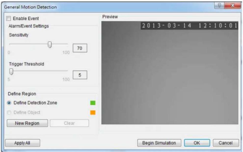
Note: General Motion Detection can also be configured by clicking Camera List > Video Analytics > General Motion Detection in the VMS Console.
Configuring and Editing Detection Windows
- Right-click the camera entry in the Device Browser, and click VI Settings > General Motion Detection.
- If a new window is desired, click the New Region button to create a new window. Up to 3 detection windows can be set for each camera. The current window will be highlighted with a red border.
- Click and drag the white dots along window border of a window to resize or reshape the window.
- Click the interior of a window to drag it to the desired position.
- Adjust the sliders: (Settings will be applied to all existing windows)
- Sensitivity - Adjusts window sensitivity from 0 (low) to 100 (high).
- Trigger Threshold - Adjusts the amount of change allowed before and event is triggered.
- Click OK to save the changes and exit the popup.
Testing Detection Windows
- Right-click the camera entry in the Device Browser, then highlight and click the VI Settings > General Motion Detection option.
- Click the Begin Simulation button enable test detection. During testing a red border will appear around any moving objects detected.
- Click End Simulation to end the simulation.
- Click OK to exit the popup.
Deleting a Detection Window
- Right-click the camera entry in the Device Browser, then highlight and click the VI Settings > General Motion Detection option.
- Highlight an existing detection window.
- Click the Clear button to delete the window.
- Click OK to save the changes and exit the popup.
Enabling or Disabling a Detection
- Right-click the camera entry in the Device Browser, then highlight and click the VI Settings > General Motion Detection option.
- Check the Enable Event box to enable detection, or uncheck the box to disable detection.
- Click OK to save the changes and exit the popup.
Opening the Help File
The help file for General Motion Detection can be attached by clicking the icon on the upper right corner of the window.
?
10.1.2. Foreign Object Detection
Foreign object detection involves using the software to analyze a video feed and detect objects that do not belong.
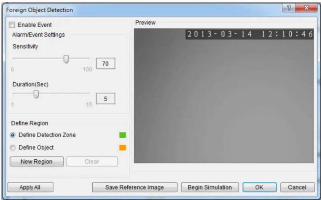
Note: Foreign Object Detection can also be configured by clicking Camera List > Video Analytics > Foreign Object Detection in the VMS Console.
Configuring and Editing Detection Windows
To configure a new detection window:
-
Right-click the camera entry in the Device Browser, and click VI Settings > Foreign Object Detection.
-
If a new window is desired, select Define Detection Zone and click the New Region button to create a new window. Up to 3 detection windows can be set for each camera. The current window will be highlighted with a red border.
-
Click and drag the white dots along window border of a window to resize or reshape the window.
-
Click the interior of a window to drag it to the desired position.
-
If an object size has not yet been defined, select Define Object and click the New Region button to create an object box.
-
Click and drag the corners of the object box to define the minimum size of objects that will be detected.
-
Adjust the sliders: (Settings will be applied to all existing windows)
Click OK to save the changes and exit the popup.
- Sensitivity - Adjusts window sensitivity from 0 (low) to 100 (high).
■ Duration - Adjusts the amount of time before an object triggers an event.
Click OK to save the changes and exit the popup.
Testing Detection Windows
To test a detection window:
- Right-click the camera entry in the Device Browser, then highlight and click the VI Settings > Foreign Object Detection option.
- Click the Begin Simulation button enable test detection. During testing a red border will appear around any foreign objects detected.
- Click End Simulation to end the simulation.
- Click OK to exit the popup.
Deleting a Detection Window
To delete a new detection window:
- Right-click the camera entry in the Device Browser, then highlight and click the VI Settings > Foreign Object Detection option.
- Highlight an existing detection window.
- Click the Clear button to delete the window.
- Click OK to save the changes and exit the popup.
Enabling or Disabling a Detection
To enable or disable the detection functions:
-
Right-click the camera entry in the Device Browser, then highlight and click the VI Settings > Foreign Object Detection option.
-
Check the Enable Event box to enable detection, or uncheck the box to disable detection.
-
Click OK to save the changes and exit the popup.
Opening the Help File
- The help file for Foreign Object Detection can be attached by clicking the icon on the upper right corner of the window.
10.1.3. Forbidden Area Detection
Forbidden area detection involves using the software to analyze the video feed and immediately detect any object in specified areas.
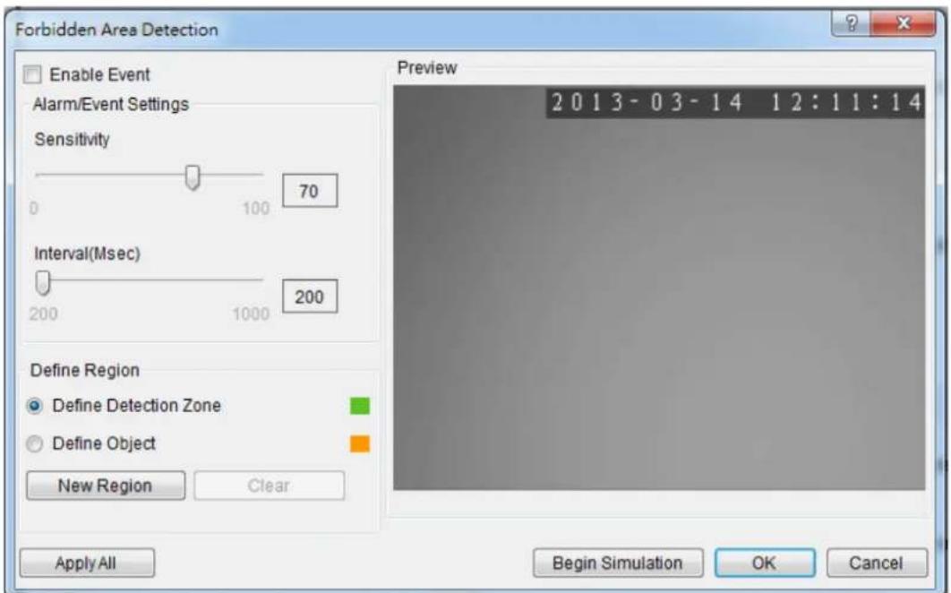
Note: Forbidden Area Detection can also be configured by clicking Camera List > Video Analytics > Forbidden Area Detection in the VMS Console.
Configuring and Editing Detection Windows
To configure a new detection window:
- Right-click the camera entry in the Device Browser, and click VI Settings > Forbidden Area Detection.
- If a new window is desired, select Define Detection Zone and click the New Region button to create a new window. Up to 3 detection windows can be set for each camera. The current window will be highlighted with a red border.
- Click and drag the white dots along window border of a window to resize or reshape the window.
- Click the interior of a window to drag it to the desired position.
-
If an object size has not yet been defined, select Define Object and click the New Region button to create an object box.
-
Click and drag the corners of the object box to define the minimum size of objects that will be detected.
-
Adjust the sliders: (Settings will be applied to all existing windows)
-
Sensitivity - Adjusts window sensitivity from 0 (low) to 100 (high).
-
Interval - Adjusts how much time between each check of the forbidden area.
-
Click OK to save the changes and exit the popup.
Testing Detection Windows
To test a detection window:
- Right-click the camera entry in the Device Browser, then highlight and click the VI Settings > Forbidden Area Detection option.
- Click the Begin Simulation button enable test detection. During testing a red border will appear around any objects detected in the forbidden area.
- Click End Simulation to end the simulation.
- Click OK to exit the popup.
Deleting a Detection Window
To delete a new detection window:
- Right-click the camera entry in the Device Browser, then highlight and click the VI Settings > Forbidden Area Detection option.
- Highlight an existing detection window.
- Click the Clear button to delete the window.
- Click OK to save the changes and exit the popup.
Enabling or Disabling a Detection
To enable or disable the detection functions:
-
Right-click the camera entry in the Device Browser, then highlight and click the VI Settings > Forbidden Area Detection option.
-
Check the Enable Event box to enable detection, or uncheck the box to disable detection.
-
Click OK to save the changes and exit the popup.
Opening the Help File
The help file for Forbidden Area Detection can be attached by clicking the icon on the upper right corner of the window.

10.1.4. Intrusion Detection
Intrusion detection involves using the software to analyze the video feed and detect intrusion larger than a certain size.
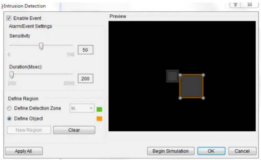
Note: Intrusion Detection can also be configured by clicking Camera List > Video Analytics > Intrusion Detection in the VMS Console.
Configuring and Editing Detection Windows
To configure a new detection window:
- Right-click the camera entry in the Device Browser, and click VI Settings > Intrusion Detection.
- If a new window is desired, select Define Detection Zone and click the New Region button to create a new window. Up to 3 detection windows can be set for each camera. The current window will be highlighted with a red border.
- Click and drag the white dots along window border of a window to resize or reshape the window.
- Click the interior of a window to drag it to the desired position.
- If an object size has not yet been defined, select Define Object and click the New Region button to create an object box.
-
Click and drag the corners of the object box to define the minimum size of the intrusion that will be detected.
-
Adjust the sliders: (Settings will be applied to all existing windows)
-
Sensitivity - Adjusts window sensitivity from 0 (low) to 100 (high).
■ Duration (Sec) - Adjusts how much time an object is missing before an event is triggered. -
Click OK to save the changes and exit the popup.
Testing Detection Windows
To test a detection window:
- Right-click the camera entry in the Device Browser, then highlight and click the VI Settings > Intrusion Detection option.
- Click the Begin Simulation button enable test detection. During testing a red border will appear if any intrusion found.
- Click End Simulation to end the simulation.
- Click OK to exit the popup.
Deleting a Detection Window
To delete a new detection window:
- Right-click the camera entry in the Device Browser, then highlight and click the VI Settings > Intrusion Detection option.
- Highlight an existing detection window.
- Click the Clear button to delete the window.
- Click OK to save the changes and exit the popup.
Enabling or Disabling a Detection
To enable or disable the detection functions:
- Right-click the camera entry in the Device Browser, then highlight and click the VI Settings > Intrusion Detection option.
- Check the Enable Event box to enable detection, or uncheck the box to disable detection.
- Click OK to save the changes and exit the popup.
Opening the Help File
The help file for Intrusion Detection can be attached by clicking the icon on the upper right corner of the window.
10.1.5. Missing Object Detection
Missing object detection involves using the software to analyze the video feed and detect missing objects larger than a certain size.
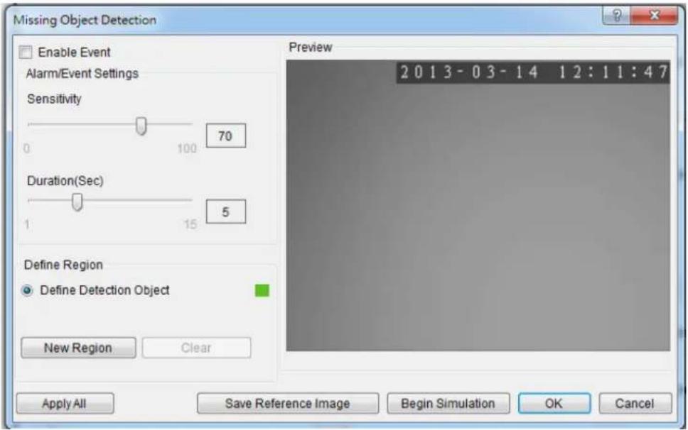
Note: Missing Object Detection can also be configured by clicking Camera List > Video Analytics > Missing Object Detection in the VMS Console.
Configuring and Editing Detection Windows
To configure a new detection window:
- Right-click the camera entry in the Device Browser, and click VI Settings > Missing Object Detection.
- If a new window is desired, select Define Detection Zone and click the New Region button to create a new window. Up to 3 detection windows can be set for each camera. The current window will be highlighted with a red border.
- Click and drag the white dots along window border of a window to resize or reshape the window.
- Click the interior of a window to drag it to the desired position.
- If an object size has not yet been defined, select Define Object and click the New Region button to create an object box.
-
Click and drag the corners of the object box to define the minimum size of the missing objects that will be detected.
-
Adjust the sliders: (Settings will be applied to all existing windows)
-
Sensitivity - Adjusts window sensitivity from 0 (low) to 100 (high).
■ Duration (Sec) - Adjusts how much time an object is missing before an event is triggered. -
Click OK to save the changes and exit the popup.
Testing Detection Windows
To test a detection window:
- Right-click the camera entry in the Device Browser, then highlight and click the VI Settings > Missing Object Detection option.
- Click the Begin Simulation button enable test detection. During testing a red border will appear if a object goes missing.
- Click End Simulation to end the simulation.
- Click OK to exit the popup.
Deleting a Detection Window
To delete a new detection window:
- Right-click the camera entry in the Device Browser, then highlight and click the VI Settings > Missing Object Detection option.
- Highlight an existing detection window.
- Click the Clear button to delete the window.
- Click OK to save the changes and exit the popup.
Enabling or Disabling a Detection
To enable or disable the detection functions:
- Right-click the camera entry in the Device Browser, then highlight and click the VI Settings > Missing Object Detection option.
-
Check the Enable Event box to enable detection, or uncheck the box to disable detection.
-
Click OK to save the changes and exit the popup.
Opening the Help File
The help file for Missing Object Detection can be attached by clicking the icon on the upper right corner of the window.

10.1.6. Tampering Detection
Tampering detection involves using the software to determine when the camera has been improperly moved or redirected.
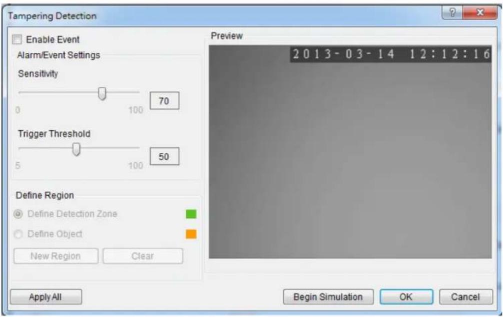
Note: Tampering Detection can also be configured by clicking Camera List > Video Analytics > Tampering Detection in the VMS Console.
Configuring Tampering Detection
To configure a new detection window:
- Right-click the camera entry in the Device Browser, and click VI Settings >Tampering Detection.
-
Adjust the sliders:
-
Sensitivity - Adjusts window sensitivity from 0 (low) to 100 (high).
-
Trigger Threshold - Adjusts the amount of change allowed before an event is triggered.
-
Click OK to save the changes and exit the popup.
Testing Tampering Detection
To test a detection window:
- Right-click the camera entry in the Device Browser, then highlight and click the VI Settings > Tampering Detection option.
- Click the Begin Simulation button enable test detection. During testing a red border if tampering is detected.
- Click End Simulation to end the simulation.
- Click OK to exit the popup.
Enabling or Disabling a Detection
To enable or disable the detection functions:
- Right-click the camera entry in the Device Browser, then highlight and click the VI Settings >Tampering Detection option.
- Check the Enable Event box to enable detection, or uncheck the box to disable detection.
- Click OK to save the changes and exit the popup.
Opening the Help File
The help file for Tampering Detection can be attached by clicking the icon on the upper right corner of the window.
10.1.7. Camera Motion Detection
Camera motion detection involves using the camera hardware to analyze the video feed and detect motion in specified areas.
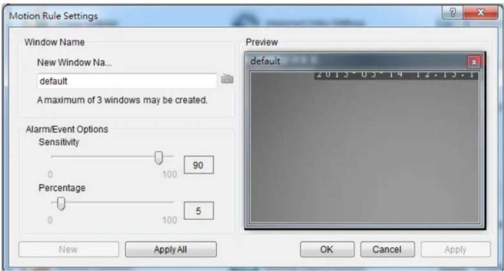
Note: Camera Motion Detection can also be configured by clicking Camera List > Video Analytics > Camera Motion Detection in the VMS Console.
Configuring and Editing Detection Windows
To configure a new detection window:
- Right click the camera entry in the Device Browser, and click VI Settings > Camera Motion Detection.
Note: You must be logged into the camera before changing settings or else the operation will fail.
-
If a new window is desired, enter a name in the New Window Name field and click the New button. Up to 3 detection windows can be set for each camera. The current window will be highlighted.
-
Click and drag the window border of a window to resize or reshape the window.
-
Click the interior of a window to drag it to the desired position.
-
Adjust the sliders: (Settings will be applied to all existing windows)
- Sensitivity - Adjusts window sensitivity from 0 (low) to 100 (high).
- Percentage - Adjusts the amount of the window that must change before an event is triggered.
- Click Apply to save the changes and OK to exit the popup.
Deleting a Detection Window
To delete a new detection window:
- Right click the camera entry in the Device Browser, then highlight and click the VI Settings > Camera Motion Detection option.
- Click the X at the top right corner of the window to delete the window.
- Click OK to save the changes and exit the popup.
Opening the Help File
The help file for Camera Motion Detection can be attached by clicking the icon on the upper right corner of the window.
?
10.1.8. Virtual Fence
Virtual fence involves using the software to create a fence-crossing detection of the demanding object.
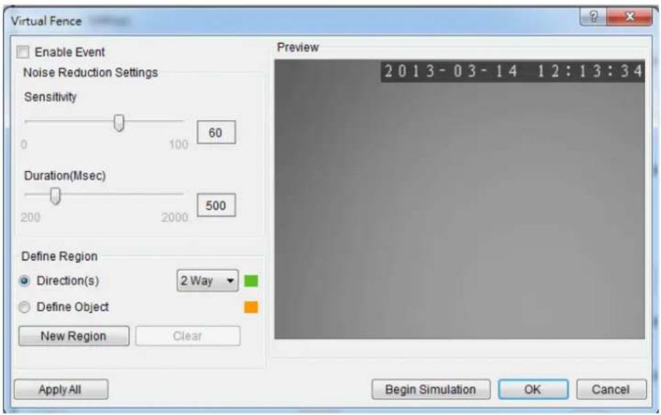
Note: Virtual Fence can also be configured by clicking Camera List > Video Analytics > Virtual Fence in the VMS Console.
Configuring and Editing Detection Windows
To configure a new detection window:
- Right-click the camera entry in the Device Browser, and click VI Settings > Virtual Fence.
- If a new window is desired, select Directions and click the New Region button to create a new window. The current window will be highlighted with a one/two-way arrow (blue means "in", green means "out").
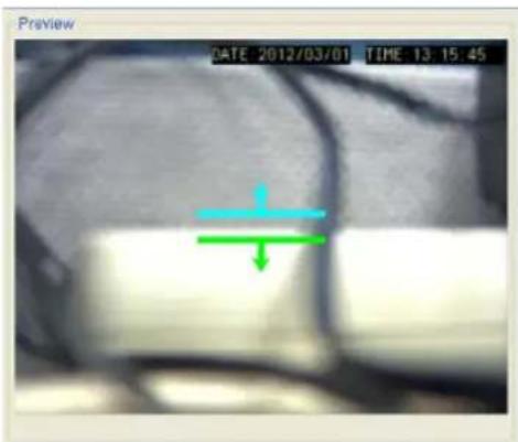
natural_image
Medical scan image showing internal anatomy with a green arrow indicating a specific region (no text or symbols present)- Click and drag the white arrows along the window border around the one/two-way arrow to resize the space between the fences/adjust the length of the fences.
- Turn the window border with the orange arrow to change the directions of the fences.
- If an object size has not yet been defined, select Define Object and click the New Region button to create an object box.
-
Click and drag the corners of the object box to define the minimum size of the fence-crossing objects that will be detected.
-
Adjust the sliders: (Settings will be applied to all existing windows)
-
Sensitivity - Adjusts window sensitivity from 0 (low) to 100 (high).
■ Duration (Sec) - Adjusts how much time between each check for the fence-crossing. -
Click OK to save the changes and exit the popup.
Testing Detection Windows
To test a detection window:
- Right-click the camera entry in the Device Browser, then highlight and click the VI Settings > Virtual Fence option.
- Click the Begin Simulation button enable test detection. During testing a red border will appear if a object goes missing.
- Click End Simulation to end the simulation.
- Click OK to exit the popup.
Deleting a Detection Window
To delete a new detection window:
- Right-click the camera entry in the Device Browser, then highlight and click the VI Settings > Virtual Fence option.
- Highlight an existing detection window.
-
Click the Clear button to delete the window.
-
Click OK to save the changes and exit the popup.
Enabling or Disabling a Detection
To enable or disable the detection functions:
- Right-click the camera entry in the Device Browser, then highlight and click the VI Settings > Virtual Fence option.
- Check the Enable Event box to enable detection, or uncheck the box to disable detection.
- Click OK to save the changes and exit the popup.
Opening the Help File
The help file for Virtual Fence can be attached by clicking the icon on the upper right corner of the window.
10.1.9. Object Counting
Object counting involves using the camera to count demanding object crossing the fences.
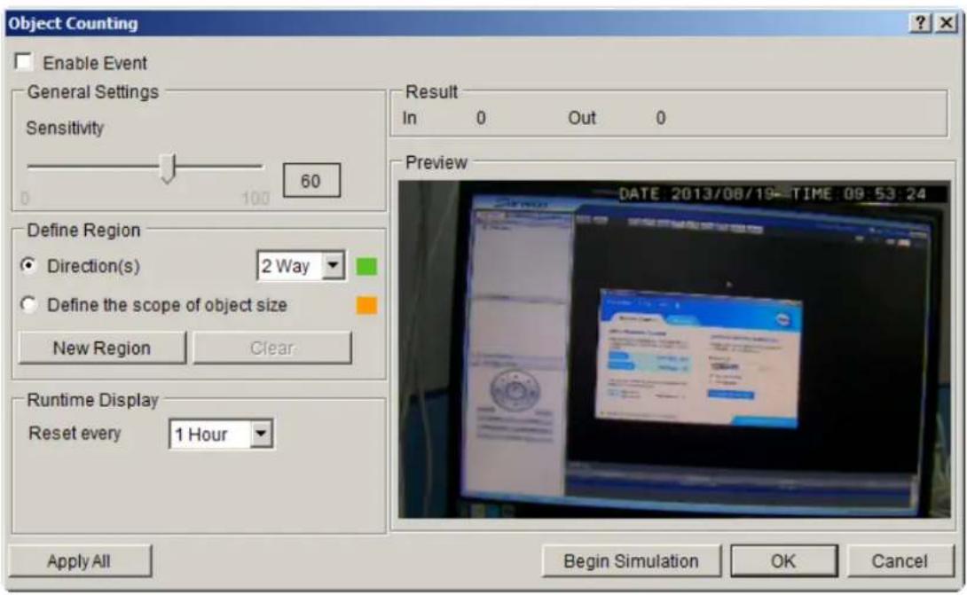
Configuring and Editing Detection Windows
To configure a new detection window:
- Right-click the camera entry in the Device Browser, and click VI Settings > Object Counting.
- If a new window is desired, select Directions and click the New Region button to create a new window. The current window will be highlighted with a one/two-way arrow (blue means "in", green means "out").
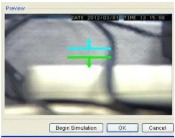
- Click and drag the white arrows along the window border around the one/two-way arrow to resize the space between the fences/adjust the length of the fences.
- Turn the window border with the orange arrow to change the directions of the fences.
- If an object size has not yet been defined, select Define Object (People Only) and click the New Region button to create an object box.
Note: (1) Only people will be counted after Define Object (People Only) is selected. (2) It is recommended that the object size is smaller than 1/4 of the live view screen.
- Click and drag the corners of the object box to define the minimum size of the fence-crossing objects that will be detected.
- Adjust the sliders: (Settings will be applied to all existing windows)
- Sensitivity - Adjusts window sensitivity from 0 (low) to 100 (high).
-
The update interval can be set as 5min, 10min, 15min, 30 min and 1 hour in Runtime Display.
-
Click OK to save the changes and exit the popup.
Testing Detection Windows
To test a detection window:
- Right-click the camera entry in the Device Browser, then highlight and click the VI Settings > Object Counting option.
- Click the Begin Simulation button enable test detection. During testing a red border will appear if a object goes missing.
- Click End Simulation to end the simulation.
- Click OK to exit the popup.
Deleting a Detection Window
To delete a new detection window:
- Right-click the camera entry in the Device Browser, then highlight and click the VI Settings > Object Counting option.
- Highlight an existing detection window.
- Click the Clear button to delete the window.
- Click OK to save the changes and exit the popup.
Enabling or Disabling a Detection
To enable or disable the detection functions:
- Right-click the camera entry in the Device Browser, then highlight and click the VI Settings > Object Counting option.
- Check the Enable Event box to enable detection, or uncheck the box to disable detection.
- Click OK to save the changes and exit the popup.
Note: (1) Object Counting can also be configured by clicking Camera List > Video Analytics > Object Counting in the VMS Console. (2) The statistical results for object counting can be seen by choosing the Counting Tab in the View Log Windows. Please refer to Log for Object Counting section for more details.
Opening the Help File
The help file for Object Counting can be attached by clicking the icon on the upper right corner of the window.
10.1.10. Going Out Detection
Going Out detection involves using the software to analyze the video feed and detect a going-out object crossing over the restricted area.
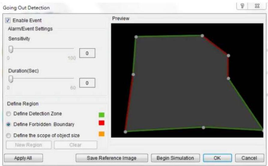
Note: Going Out Detection can also be configured by clicking Camera List > Video Analytics > Going Out Detection in the VMS Console.
Configuring and Editing Detection Windows
To configure a new detection window:
- Right-click the camera entry in the Device Browser, and click VI Settings > Going Out Detection.
- If a new window is desired, select Define Detection Zone and click the New Region button to create a new window. Only 1 detection window can be set for each camera.
- Click and drag the white dots along window border of a window to resize or reshape the window.
- Click the interior of a window to mark the restricted line; once clicked, the clicked line will turn red. The red lines are the boundaries. Up to 8 boundaries can be set.
-
If an object size has not yet been defined, select Define Object and click the New Region button to create an object box.
-
Click and drag the corners of the object box to define the minimum size of the objects that will be detected.
- Adjust the sliders: (Settings will be applied to all existing windows)
- Sensitivity – Adjusts window sensitivity from 0 (low) to 100 (high).
■ Duration (Sec) - Adjusts how much time an object is missing before an event is triggered.
- Click OK to save the changes and exit the popup.
Testing Detection Windows
To test a detection window:
- Right-click the camera entry in the Device Browser, then highlight and click the VI Settings > Going Out Detection option.
- Click the Begin Simulation button enable test detection. During testing a red border will appear if any intrusion found.
- Click End Simulation to end the simulation.
- Click OK to exit the popup.
Deleting a Detection Window
To delete a new detection window:
- Right-click the camera entry in the Device Browser, then highlight and click the VI Settings > Going Out Detection option.
- Highlight an existing detection window.
- Click the Clear button to delete the window.
- Click OK to save the changes and exit the popup.
Enabling or Disabling a Detection
To enable or disable the detection functions:
- Right-click the camera entry in the Device Browser, then highlight and click the VI Settings > Going Out Detection option.
-
Check the Enable Event box to enable detection, or uncheck the box to disable detection.
-
Click OK to save the changes and exit the popup.
Opening the Help File
The help file for Going Out Detection can be attached by clicking the icon on the upper right corner of the window.

10.1.11. Tailgating Detection
Tailgating detection involves using the software to analyze the video feed and detect a tailgating object crossing over the restricted area.
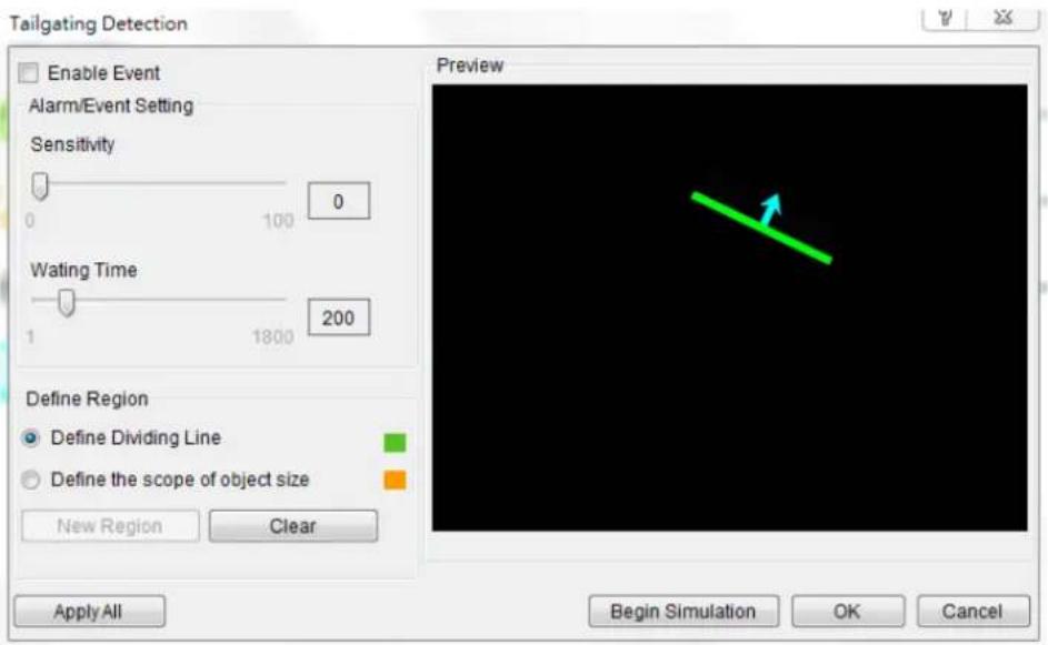
Note: Tailgating Detection can also be configured by clicking Camera List > Video Analytics > Tailgating Detection in the VMS Console.
Configuring and Editing Detection Windows
To configure a new detection window:
- Right-click the camera entry in the Device Browser, and click VI Settings > Tailgating Detection.
- If a new window is desired, select Define Dividing Line and click the New Region button to create a new dividing line. Only 1 dividing line can be set for each camera.
- Click and drag the created dividing line to the desire position and direction.
- If an object size has not yet been defined, select Define Object and click the New Region button to create an object box.
- Click and drag the corners of the object box to define the minimum size of the objects that will be detected.
-
Adjust the sliders: (Settings will be applied to all existing windows)
-
Sensitivity – Adjusts window sensitivity from 0 (low) to 100 (high).
-
Waiting Time (Sec) - Adjusts how much time an object is tailgating before an event is triggered.
-
Click OK to save the changes and exit the popup.
Testing Detection Windows
To test a detection window:
- Right-click the camera entry in the Device Browser, then highlight and click the VI Settings > Tailgating Detection option.
- Click the Begin Simulation button enable test detection. During testing a red border will appear if any intrusion found.
- Click End Simulation to end the simulation.
- Click OK to exit the popup.
Deleting a Dividing Line
To delete a new dividing line:
- Right-click the camera entry in the Device Browser, then highlight and click the VI Settings > Tailgating Detection option.
- Highlight the dividing line.
- Click the Clear button to delete the line.
- Click OK to save the changes and exit the popup.
Enabling or Disabling a Detection
To enable or disable the detection functions:
- Right-click the camera entry in the Device Browser, then highlight and click the VI Settings > Tailgating Detection option.
- Check the Enable Event box to enable detection, or uncheck the box to disable detection.
- Click OK to save the changes and exit the popup.
Opening the Help File
The help file for Tailgating Detection can be attached by clicking the icon on the upper right corner of the window.

10.2. Alarm Rules
VMS Client provides robust alarm handling features.
To access these features right-click the Server entry and then highlight and click the Alarm Rule Settings option.
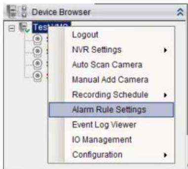
Note: Alarm Rule Settings can also be accessed by clicking Server > General Tasks > Alarm Rule Settings or Server Entry > Common Tasks > Common Server Tasks > Alarm Rule Settings in the VMS Console.
In the alarm rule settings, you can combine the alarm trigger conditions with action items such as event notification, video recording, and/or camera movements. Multiple alarm rules can be created using the following elements:
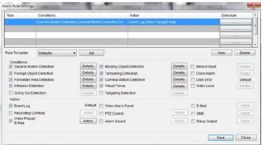
-
Rule: A short description. For example, "east -fence intrusion detection" or "front entrance access control."
-
Condition: Specifies triggering conditions such as Motion/Video loss/Sensor input/Clock Alarm, etc.
-
Action: Specifies the action to take when the alarm is triggered.
-
Schedule: Allows the user to schedule the application of specific Alarm rules. This is useful in cases such as applying rules to non-office hours.
10.2.1. Adding an Alarm Rule
-
Click the New button.
-
Enter a short description for the new rule in the Add Rule field.
-
Choose conditions and actions. Click the ..... button in the alarm field to set up a schedule for the rule. These selections are described in the following sections.
-
Click the Save button to save the rule.
Alarm Conditions
The follow alarm conditions can be set to trigger the alarm:
General Motion Detection
When configuring a camera, a detection area can be specified for General Motion Detection. After the detection area is specified, detection can be activated and an alarm handling scheme configured in this menu.
Clicking on the Detail button will pull up a menu listing all the devices with General Motion Detection active.
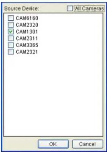
From this menu, click the checkboxes next to the cameras that have General Motion Detection configured. Optionally, check the All Cameras check box to use all the cameras available. Click the OK button to exit the menu.
Foreign Object Detection
When configuring a camera, a detection area can be specified for Foreign Object Detection. After the detection area is specified, detection can be activated and an alarm handling scheme configured in this menu.
Clicking on the Detail button will pull up a menu listing all the devices with the Foreign Object Detection active.
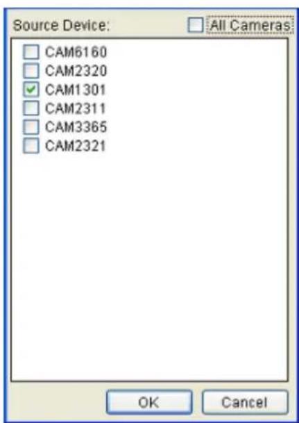
From this menu, click the checkboxes next to the cameras that have Foreign Object Detection configured. Optionally, check the All Cameras check box to use all the cameras available. Click the OK button to exit the menu.
Forbidden Area Detection
When configuring a camera, a detection area can be specified as forbidden for the Forbidden Area Detection function. After the area is specified, detection can be activated and an alarm handling scheme configured in this menu.
Clicking on the Detail button will pull up a menu listing all the devices with the Forbidden Area Detection active.
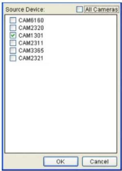
From this menu, click the checkboxes next to the cameras that have a Forbidden Area configured. Optionally, check the All Cameras check box to use all the cameras available. Click the OK button to exit the menu.
Intrusion Detection
When configuring a camera, a detection area can be specified for Intrusion Detection. After the detection area is specified, detection can be activated and an alarm handling scheme configured in this menu.
Clicking on the Detail button will pull up a menu listing all the devices with the Intrusion Detection active.
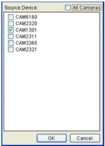
From this menu, click the checkboxes next to the cameras that have Intrusion Detection configured. Optionally, check the All Cameras check box to use all the cameras available. Click the OK button to exit the menu.
Going Out Detection
When configuring a camera, a detection area can be specified for Going Out Detection. After the detection area is specified, detection can be activated and an alarm handling scheme configured in this menu.
Clicking on the Detail button will pull up a menu listing all the devices with the Going Out Detection active.

From this menu, click the checkboxes next to the cameras that have Going Out Detection configured. Optionally, check the All Cameras check box to use all the cameras available. Click the OK button to exit the menu.
Missing Object Detection
When configuring a camera, an object can be specified for Missing Object Detection. After the object is specified, detection can be activated and an alarm handling scheme configured in this menu.
Clicking on the Detail button will pull up a menu listing all the devices with Missing Object Detection active.
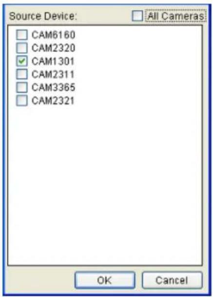
From this menu, click the checkboxes next to the cameras that have Missing Object Detection configured. Optionally, check the All Cameras check box to use all the cameras available. Click the OK button to exit the menu.
Tampering Detection
When configuring a camera, a detection sensitivity and trigger threshold can be specified for the Tampering Detection. After the detection sensitivity is specified, detection can be activated and an alarm handling scheme configured in this menu.
Clicking on the Detail button will pull up a menu listing all the devices with the Tampering Detection active.
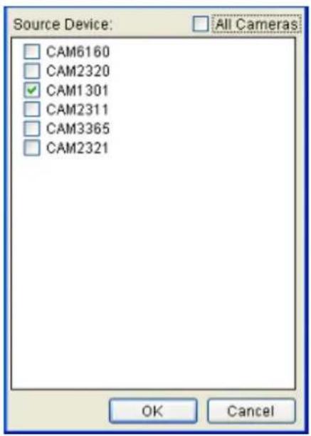
From this menu, click the checkboxes next to the cameras that have Tampering Detection configured. Optionally, check the All Cameras check box to use all the cameras available. Click the OK button to exit the menu.
Camera Motion Detection
When configuring a camera, a detection area can be specified for Camera Motion Detection. After the detection area is specified, detection can be activated and an alarm handling scheme configured in this menu.
Clicking on the Detail button will pull up a menu listing all the devices with Camera Motion Detection active.
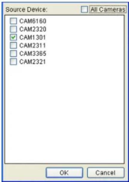
From this menu, click the checkboxes next to the cameras that have Camera Motion Detection configured. Optionally, check the All Cameras check box to use all the cameras available. Click the OK button to exit the menu.
Virtual Fence
When configuring a camera, a detection area can be specified for Virtual Fence. After the detection area is specified, detection can be activated and an alarm handling scheme configured in this menu.
Clicking on the Detail button will pull up a menu listing all the devices with Virtual Fence Detection active.

Tailgating Detection
When configuring a camera, a detection area can be specified for Tailgating Detection. After the detection area is specified, detection can be activated and an alarm handling scheme configured in this menu.
Clicking on the Detail button will pull up a menu listing all the devices with the Tailgating Detection active.
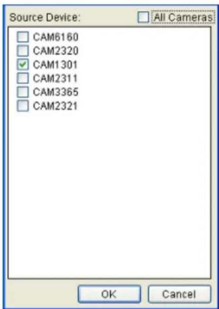
From this menu, click the checkboxes next to the cameras that have Tailgating Detection configured. Optionally, check the All Cameras check box to use all the cameras available. Click the OK button to exit the menu.
Sensor Input
The alarm is triggered by a sensor input. For example this may include doorway entry sensors that are connected to the camera system. Clicking on the Detail button will pull up the Sensor Input Settings menu, listing all the cameras. From this menu, click the checkboxes next to the cameras that will be used to trigger the Alarm. Optionally, check the All Cameras check box to use all the cameras available. Click the OK button to exit the menu.
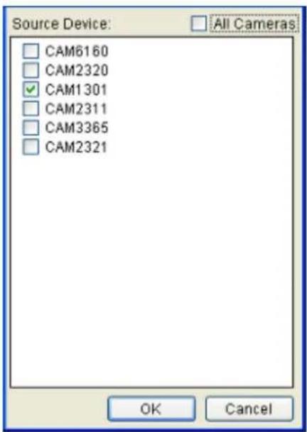
Clock Alarm
When a preset time is reached, the alarm is triggered. The Clock Alarm is triggered only on the day it is configured. Clicking on the Detail button will pull up the Clock Alarm menu.
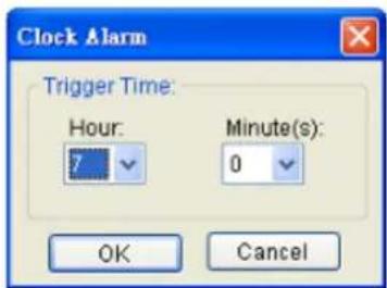
From this popup select the hour and minute the alarm will be triggered. Click the OK button to exit the menu.
Disk Error
The alarm is triggered when a disk drive failure occurs.
Video Loss
When video input is lost, the alarm is triggered. Clicking on the Details button will pull up the Video Loss Settings menu, listing all the cameras. From this menu, click the checkboxes next to the cameras that will be used to trigger the Alarm. Optionally, check the All Cameras check box to use all the cameras available. Click the OK button to exit the menu.
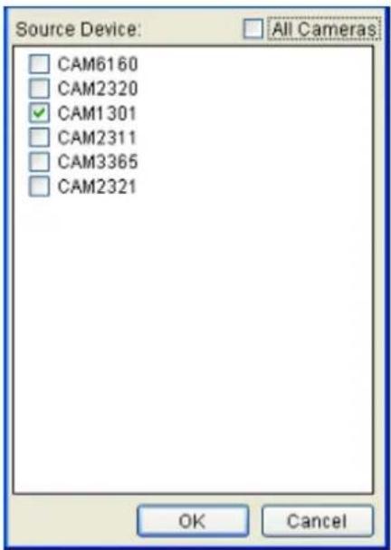
Alarm Actions
The following alarm actions can be taken when the alarm is triggered:
Event Log
The system issues event messages when the alarm is triggered.
Recording Controls / Video Popup
When the alarm is triggered, the system records video onto the storage. Clicking on the Action button will pull up the Recording Settings menu.
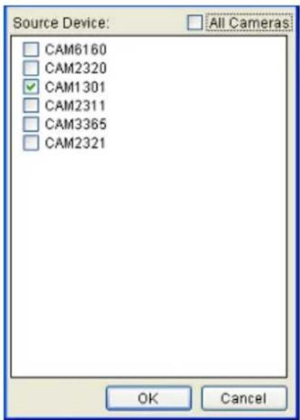
Use the checkboxes within to select cameras that will be recorded. Optionally, check the All Cameras check box to use all the cameras available. Click the OK button to exit the menu.
E-Map
When the alarm is triggered, a popup video appears on the local client.
Clicking the Action button will pull up a menu.
Video Alarm Panel
This will display the video feed thumbnail in the video alarm panel for review and playback.
PTZ Control
When the alarm is triggered, a Pan-Tilt-Zoom action can be set to slew the camera to a particular position. For example, clicking on the Action button brings up the PTZ Action Settings menu. In this menu:
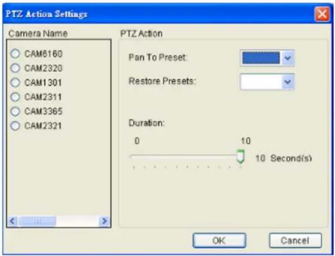
- Choose a camera from the list.
- Select a preset point from the Pan to Preset dropdown that the camera will pan to.
- Select the preset that the camera will return to from the Restore Presets dropdown.
- Specify a duration that the camera will stay at the Pan to Action preset before returning to the Restore to Preset preset using the Duration slider. Click Apply to save the settings.
- Click OK to exit the menu.
Alarm Sound
When the alarm is triggered, the system will play an audible alarm sound. Clicking on the Action button will pull up the Warning Sound menu, listing available sounds.
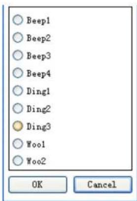
Choose a sound by clicking the radio box next to the desired sound. Click the OK button to exit the menu.
When the alarm is triggered, an E-Mail will be sent. Checking this option will bring up the E-mail Settings menu.
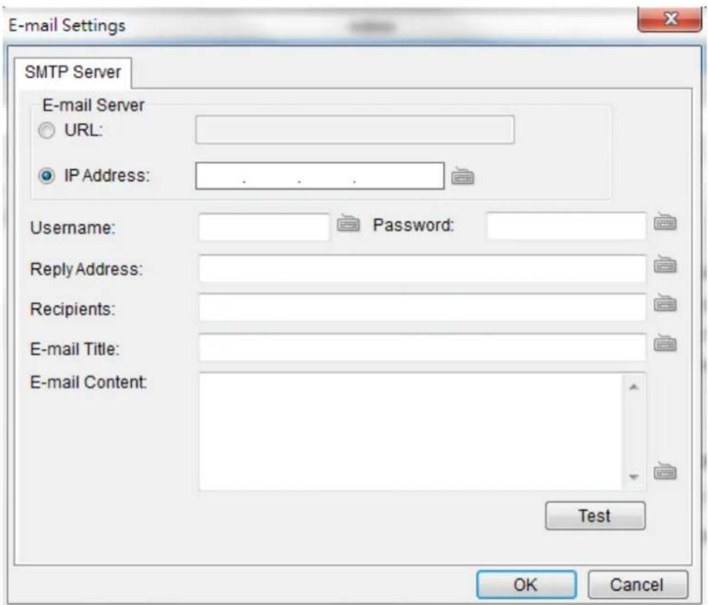
- In the SMTP Server tab, under the E-mail Server heading, you may either enter the URL (such as smtp.abc.com) or IP address of the SMTP server that the Server will use to deliver E-mail notifications. The SMTP server configured here must support Unicode Transformation Format-8 (UTF-8) encoding.
- Enter the user name for the Server email account in the Username field.
- Enter the password for the Server email account in the Password field.
-
Enter a valid E-mail address in the Reply Address field. This address will be the default sender listed in E-mails sent from the Server.
-
Enter one or more E-mail addresses in the Recipients: field. These address(es) will receive notifications from the Server. Multiple addresses can be entered by separating individual addresses with semi-colons “;”.
- Enter the subject of your notification E-mails, e.g., Server-xxxsite1notification in the E-Mail Title field.
- Enter a short message in the large field to describe the Server or a surveillance network.
- (Optional) Click Test to send a test message to the E-mail addresses listed.
- Click the OK button to exit E-mail settings.
SMS
When the alarm is triggered, an SMS message will be sent. Checking this option will bring up the SMS Settings menu.
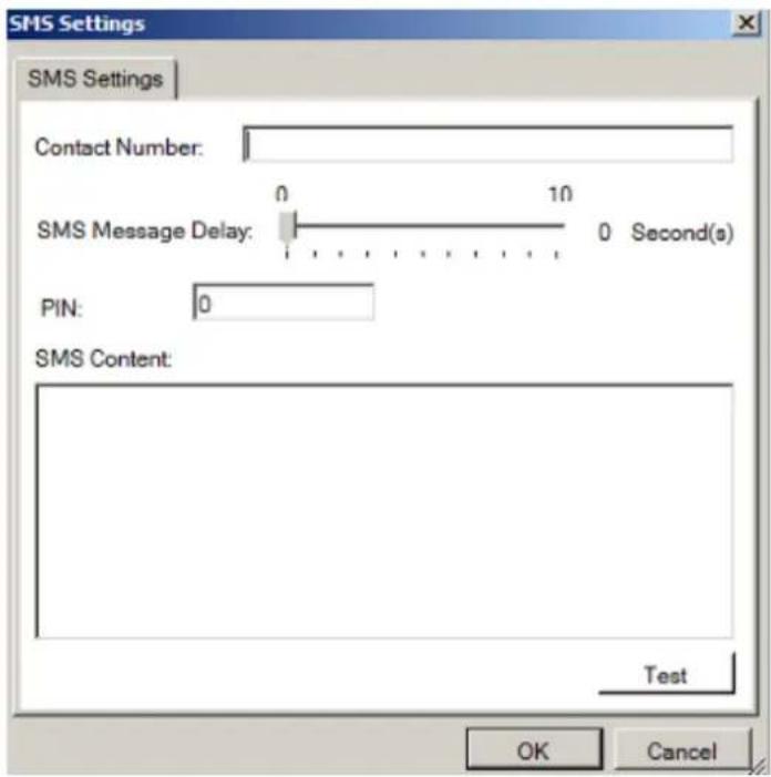
Note: Drivers for supported GSM/ GPRS modems have already been installed on the server. Currently, only the WaveCOM-M1206B is supported. Use COM1 on the Server to connect to a GSM modem.
- In the Contact Number field, enter the phone numbers that will receive SMS notifications. Be sure to include the area code, e.g., "86", in front
of phone numbers. Use commas, “,” to separate individual phone numbers.
-
Use the slider bar to select a delay between the occurrence of an event and SMS message delivery.
-
(Optional) If a SIM PIN is required, enter the PIN code in the PIN field. Note that applying incorrect PIN code may disable your SIM card.
Note: To change the PIN code, remove the SIM card from your GSM modem. Use a cell phone to change the PIN code and then re-install SIM card into the GSM modem. Changing PIN codes is not recommended because a configuration failure may disable your SIM card.
-
In the SMS Content field, type a simple description to include in the outgoing SMS messages
-
(Optional) Click Test to send a test message to the phone numbers listed.
-
Click the Apply button to apply the changes.
-
Click the OK button to exit SMS settings.
Relay Output
When the alarm is triggered, a signal will be relayed to an external source such as a light switch, siren, or other external link. Clicking on the Action button brings up the External Relay Settings menu. In this menu:
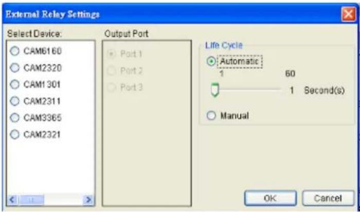
-
Choose a camera from list.
-
Select an output port to relay to.
-
Select output duration, from 0 to 60 seconds.
-
Click the OK button to exit the menu.
Alarm Scheduling
When the alarm is created, click the .....button located in the scheduling column of the alarm listing to bring up the Alarm Rule Schedule menu. This displays a table with the days of the week as the columns, and hours as the rows, allowing the user to schedule the alarm on exact hours.
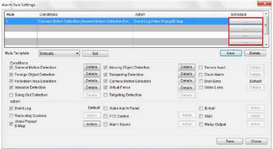
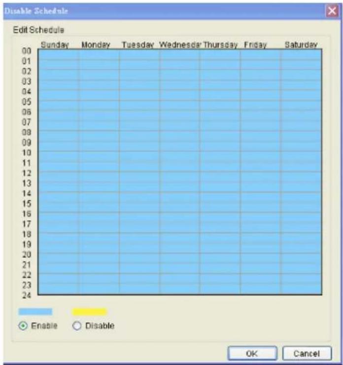
From this menu, use the following steps to schedule the alarm:
- Choose the rule that you wish to apply the schedule to.
- Click the Enable or Disable button to bring up a "paintbrush."
- Click the cursor on the table to "paint" in a schedule. You may click and drag to paint a wide area.
For example, if you wish to disable the alarm on Tuesday at 6pm, you would click the box Tuesday-18:00. Disabled time periods are highlighted in yellow.
Click the OK button to apply the changes and exit the menu.
10.3. Alarms View and Notification
There are three main ways that Alarm information is displayed when in the live view mode.
10.3.1. Live View Event Log
The first way that Alarms are displayed is in the Event Log section of the live view screen. As alarms come in, they are displayed in this area. The area can be minimized using the double arrow at the top right corner of the area.
| Event Log | |||
| Camera Name | Data/Time | Log Type | Link |
| CAV2311 | 2012-02-28 17:27:20 | Video Log | oo |
| 2012-02-28 17:21:00 | User Login | ||
The Event Log displays the camera the alarm occurred on, the date, the alarm type, and if applicable a link to the live-view feed of the camera. Clicking on the link will open the camera's live-view in a popup.
10.3.2. Alarm Popups
Alarms can be configured to display a popup window when triggered.
Up to 4 windows can be popped up at the same time. If there's a fifth alarm occurs, the VMS will close the oldest popup window and show the new popup.
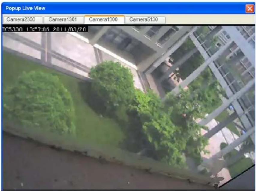
When the alarm is triggered the Open Popup Window button

will flash red. When this occurs, clicking the button will open a popup.
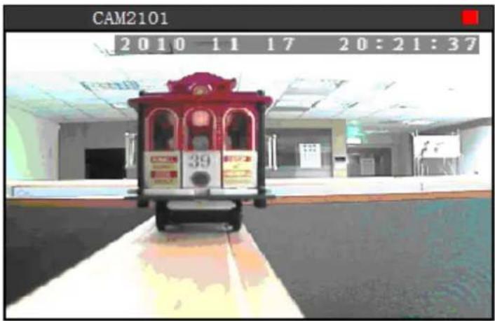


Triggering Conditions: Camera Motion Detection
Camera Name:
CAM2101
Time: 11/17/2010 6:41:11 PM
Alarm Sleep Time:
Minutes
Seconds
All Cameras

The popup will display the alarm trigger condition, the camera that triggered the alarm as well as live feed from this camera, the time of the alarm, and a custom configurable message. Any additional popups can be viewed using the left and right arrows located below the video feed.
Setting Popup Sleep Time
A skip time, in which similar alarms will not trigger a popup for the camera in question, can be configured in the Alarm Sleep Time box. Using the drop-downs, specify the number of minutes and seconds of skip time. Click Apply to save your settings.
Clicking the OK button will close the window and save the sleep settings. Clicking the Cancel button will close the window without saving the sleep settings.
10.3.3. Video Panel
Alarms can be configured to display in the Video Panel, located to the left of the main viewing area. When an alarm configured in this manner is triggered, a thumbnail of the triggering event will be displayed in the panel, and actions can be taken from this panel.
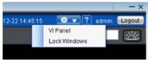
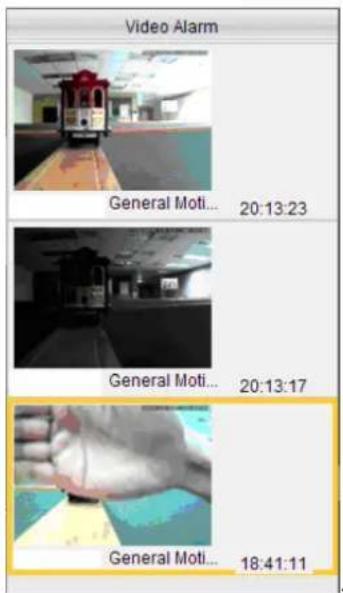
Note: VI Panel functionality can also be enabled under Server > Other Tasks > VI Panel in the VMS Console.
Playback from Video Alarm Panel
The server is configured to record up to 45 minutes of video after an alarm is triggered. To play back this video, right click the thumbnail and select Play> [Time Length]. A popup will open with the desired playback. Time lengths available are dependent on, and will not exceed the post-alarm recording time set in Pre/Post Alarm Recording Settings.
Tagging an Alarm Thumbnail
Another unique feature of alarms in the alarm panel, is that they can be tagged for future reference. To tag the alarm, right-click the thumbnail and select Mark > [Label]. Labels available are dependent on system configurations, but the default labels are Mark, Check, Clear, Suspicious.
10.4. Event Log
The event log is a comprehensive repository of all the events that occur on the system. To access the event log after logging into the system, the system log can be accessed by right-clicking the Server entry and choosing the View Log entry. The View Log window will display.
The log viewer displays events, split into three types, System events, which deal with individual modules, Camera events, which deal with cameras and Operational events which deal with users.
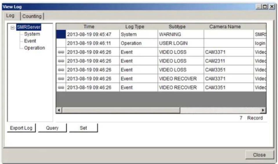
Note: Event Log can also be viewed by clicking Server Entry > Common Tasks > Common Server Tasks > View Log or Server > General Tasks > View Log in the VMS Console.
10.4.1. Exporting a Log
If log entries exist, they may be exported by clicking on the Export Log button at the bottom of the View Log screen. This will open a dialog box, which prompts the user to choose a location, and fill in a name for the saved log. Fill out the location and filename information and click OK to save the logfile.
10.4.2. Searching the Event Log
Within the View Log screen, click the Query button to bring up the Query Log dialog box.
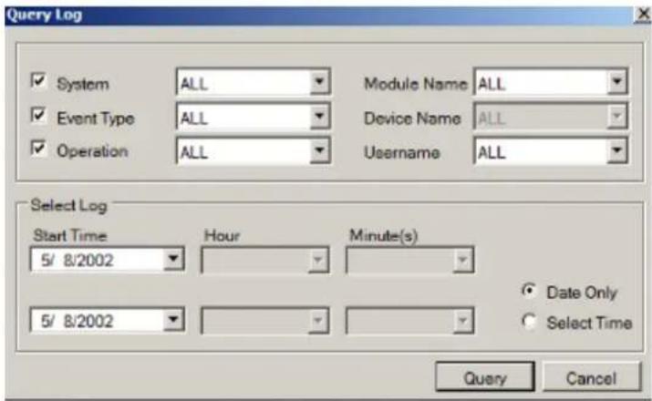
Within this dialog, the user may choose to narrow the search to the three major event types by selecting the checkbox beside the event type:
System Type
These are errors that occur within individual system modules. In the corresponding selection box, the user can specify a severity (debug, warning, error and fatal in increasing severity) of the event. The user may also choose to search all of the severities.
Module Name
The corresponding subfield for System Type is Module Name. In this selection box, the user can specify a module to search for errors on. The user may also choose to search over all modules by choosing All.
Event Type
These include errors that occur with cameras. Events include motion detection, video loss, sensor input, clock alarm, disk error and RAID failure. The user may also choose to search over all these types.
Source Device
This subfield contains a list of all the cameras installed on the system. The events can be further narrowed to focus on a single camera by choosing it, or the search can be done over all cameras by choosing All.
Operation Type
These events include the console startup and stop, system usage, and other events that occur during system operation.
User Name
Using the User Name subfield a search can be narrowed down to an individual user. This selection list contains all the users configured on the system. All the users can be included by selecting All.
Performing a Search
To perform a search of the log files:
- If desired, narrow the search by selecting an event type and subfield to search over. More than one event type can be searched.
- Choose a start date and an end date to search over using the calendar drop-downs.
- If desired, click Select time and select an hour and minute for the start and end times to further narrow the search.
- Click the Query button. The results will show in the main View Log Screen. Mousing over individual entries will display the details for that entry at the bottom of the Log Viewer.
10.4.3. Event Log Setup
The event log settings can be changed by clicking on the Set button located at the bottom of the View Log screen.
From this screen, the slider can be adjusted set the number of days that the system will store each type of log. Days range from 10 to 90 days.
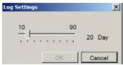
10.4.4. Log for Object Counting
Users can adjust the object counting duration and see the statistical results by choosing the Counting tab in the View Log Window.
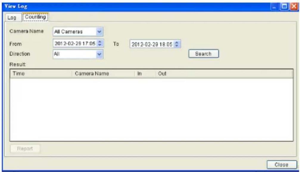
Object counting report can be exported by clicking the Report button:
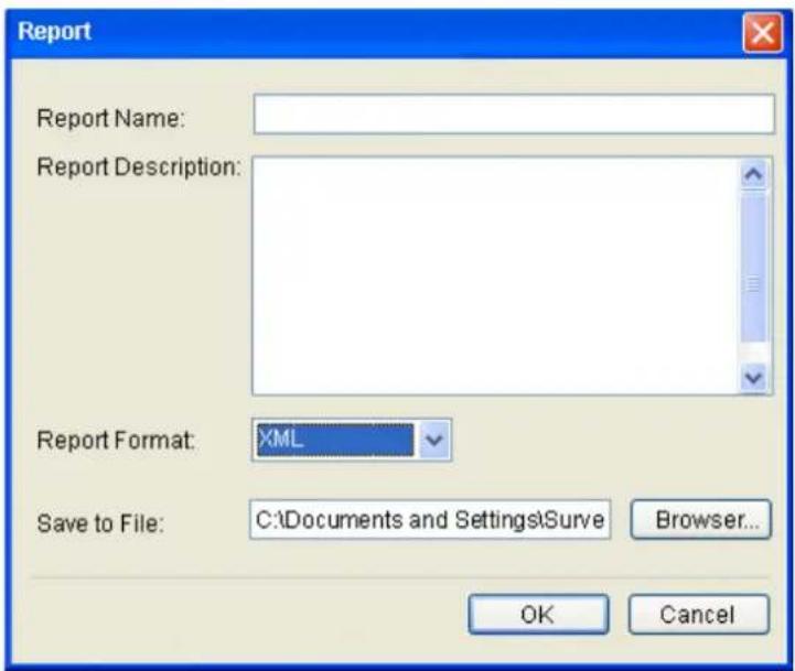
- Input the report name and report descriptions:
■ Report name: Cannot be NULL. MAX: 64 bytes.
■ Report description: MAX: 1024 bytes.
- Select the report format.
- Specify a directory for file saving.
10.4.5. System Alarm View
In addition to the event log, the system alarms will also be displayed at the bottom of the Live View screen.
Chapter 11. Search and Playback
In many cases, such as investigations or for reference purposes, it may be useful to be able to replay video streams. The Server has the ability to store video from the IP cameras, as well as playback and export this video information.
11.1. Introduction
Note: You must be logged into a server to access playback functionality.
The VMS has 3 distinct playback functions:
Time Search – Plays back according to a time period specified by the user.
VI Search – Applies a VI functionality to a recorded video stream.
Event Search – Searches the video stream for distinct events.
Note: Event Search is recommended rather than VI Search, since VI Search uses more bandwidth.
These functions may be accessed by clicking on the Playback tab located directly above the Device Browser window in the live view screen.
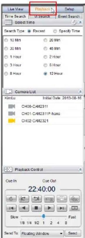
11.2. Date/Time Search
Time based playback can be accessed using the Time Search tab at the top of the screen. This search allows you to specify the time of the clip you want to view.

11.2.1. Time Selection
There are two types of time selections that can be made: Recent Time and Specified Time.
Recent Time
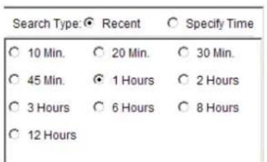
To perform a recent time search, click the Recent option in the time selection box. Choose one of the simple time choices to perform playback/search from that time period.
Specified Time
A specified time search can be selected by choosing the Specify Time option from the time selection box, and involves defining a time and date for the playback/search. Using the calendar and time boxes, specify a specific period to search/playback.
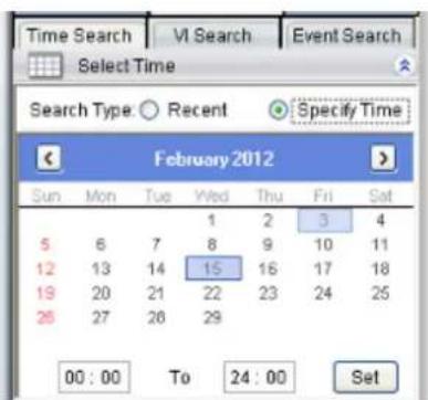
11.2.2. Use of 1x/4x Views
Users have the option of viewing up to 4 recorded video streams at once, or just one stream at a time. Either of these options can be chosen by clicking on corresponding button in the button area above the main view screen. In both cases functionality and operation is the same.
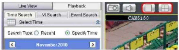
Note: 4x view is not available for SMR series.
11.2.3. Camera Selection
Once a time period has been selected, the cameras available for each period will be listed in the Camera List. These cameras can then be dragged into one the search/ playback box (es).
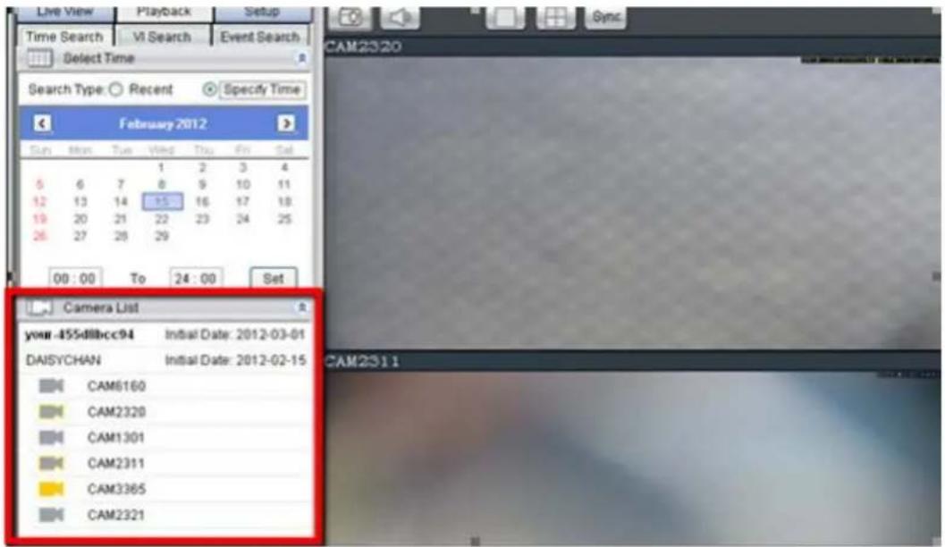
11.2.4. Timeline
After choosing the cameras to view, the timeline for the camera is displayed below the video window.
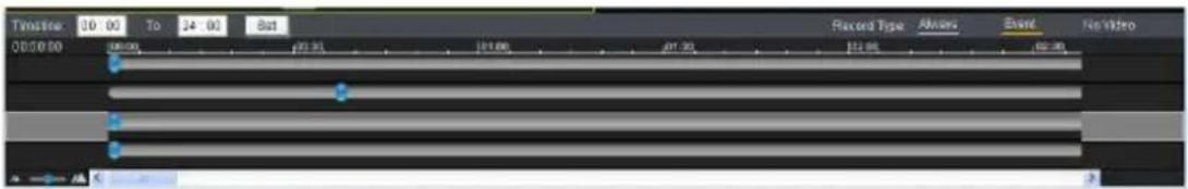
The timeline window displays a graphic representation of the video information available for the camera on the date and timeframe you have chosen in the Select Date window. You may choose to reset the timeframe to be displayed by using the dropdown at the top of the timeline.
The timeline will, at most, show a period of a little more than 3 hours. If the timeframe that you desire to view is larger than this, the remaining portion of the timeline can be viewed by using the scrollbar located beneath the timeline.
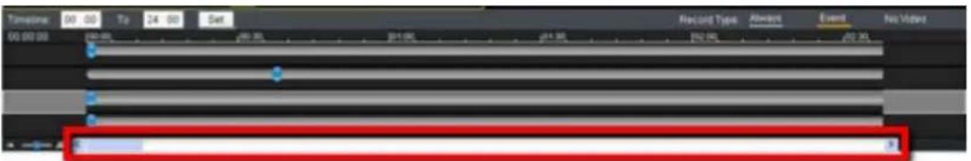
The amount of time displayed in the timeline can also be adjusted using the slider located next to the scrollbar. Sliding the indicator toward the right will cause a smaller amount of time to be displayed along the length of the timeline. In 4 camera mode, the timelines for the separate feeds will be locked to the same time period.
Once a timeline is loaded, the viewer will be able to see what kind of information is available. The timeline will be divided into 5-minute segments, with each segment colored according to what type of information it contains.
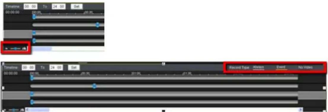
The colors are explained below:
| Color Meaning | |
| Light Grey | The camera was set to Record Always and there is video |
| Yellow Video due to an alarm trigger | |
| Dark Grey | There is no video for this segment. |
There are also two types of events that will be recorded on the timeline. These events will be displayed as vertical striping on the normal color. If a motion sensor has been triggered during a period of recording, vertical red stripes will appear, and if another type of sensor (pressure, window/door, etc) is triggered, vertical red stripes will also appear.
11.2.5. Playback
Once a timeline has been loaded, you may choose the point to begin playback. This is done by clicking the timeline. After selecting the start point you may start playback.
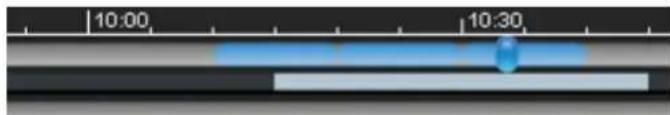
To start playback of a camera's video feed, ensure that the video is selected (the pane, timeline and camera name will be highlighted in yellow). Select feeds by clicking the corresponding pane, timeline, or camera name. Once you have selected a camera, you may use the buttons in the Playback Control Area to control the playback. Playback time is denoted above the control buttons.
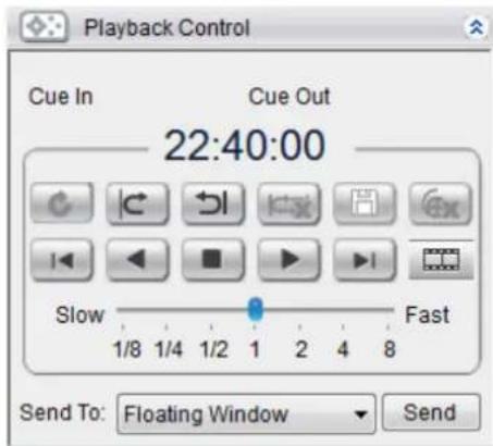
Note: The system may take a while to buffer the video before playback starts. A status line above the timeline will indicate portions that have been buffered. Jumping to unbuffered points in the video will cause the system to display an error message.
Clicking on a selected portion of the timeline will cause playback to jump to the point that you have clicked on. You must start playback separately for each feed you wish to view.
The following table explains the buttons:
 | Starts video playback. |
 | Reverses video playback. |
 | Stops video playback. |
 | Jumps to the next segment. |
 | Jumps to the previous segment. |
 | Clears the cue-in and cue-out markers. |
 | Set Cue-In marker for clip start |
 | Set Cue-Out marker for clip end |
 | Loop, continuous playback within Cue-In & Cue-Out |
 | Saves video clips/ Exports selected clips. |
 | Deletes selected clips |
 | Real time mode |
 | Frame by frame mode |
 | Just key frame mode |
Advanced Video Settings
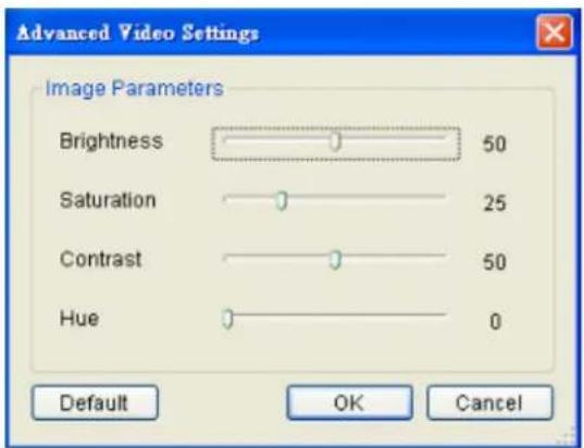
Right-clicking a panel and selecting Advanced Video Settings will bring up a menu that allows you to drag sliders and adjust the following:
■ Brightness
■ Saturation
- Contrast
■ Hue
Synchronized Playback
At most 4-channel concurrent and synchronized playback can be displayed by clicking the Sync button in the button area.
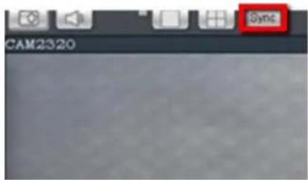
Note: 4-channel synchronized playback is not available for SMR series.
Capturing Screenshot
- Click the Capture button located in the button area.
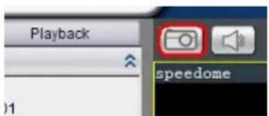
-
In the Path field enter a file path and filename for the screenshot. Alternately, you may also click Browse and select a file path.
-
(Optional) You may click Remove Mosaic and enter a valid Username and Password to remove any privacy-mask mosaicing.
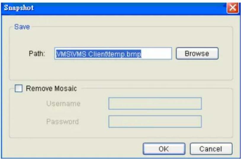
- Click OK to save the screenshot.
Capturing Video Clip
- Make sure that the video clip is playing.
- When the beginning of the segment to be captured is reached, click the Cue In button.
- When the end of the segment to be captured is reached, click the Cue Out button.
- Click the Save Video Clip button beside the Cue In and Cue Out buttons. A system popup will open prompting for a filename and location for the video clip.
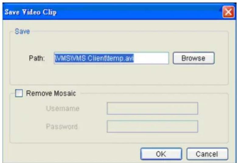
- (Optional) Change the filename and file path. If you do not change the file details, the default save location for the video clip will be your installation path.
- (Optional) You may click Remove Mosaic and enter a valid Username and Password to remove any privacy-mask mosaicing.
10.3. VI Search
A VI search involves applying VI to existing recorded video in order to locate a specific event or action. To access the VI search, click the VI Search tab in the Playback context.
10.3.1. Creating a VI Search

Time Selection
There are two types of time selections that can be made for each playback: Recent Time and Specified Time.
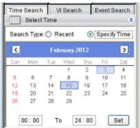
Recent Time
To perform a recent time search, click the Recent option in the time selection box. Choose one of the simple time choices to perform playback/search from that time period.
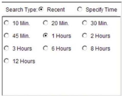
Specified Time
A specified time search can be selected by choosing the Specify Time option from the time selection box, and involves defining a time and date for the playback/ search.
Using the calendar select a date for search/ playback. Once a date is selected, clicking on the boxes will allow you to specify a specific period to search/ playback in 10 minute increments.
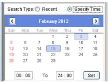
Camera Selection
Once the search time range has been specified, a list of cameras with video recorded during the period specified will appear in the Camera List.
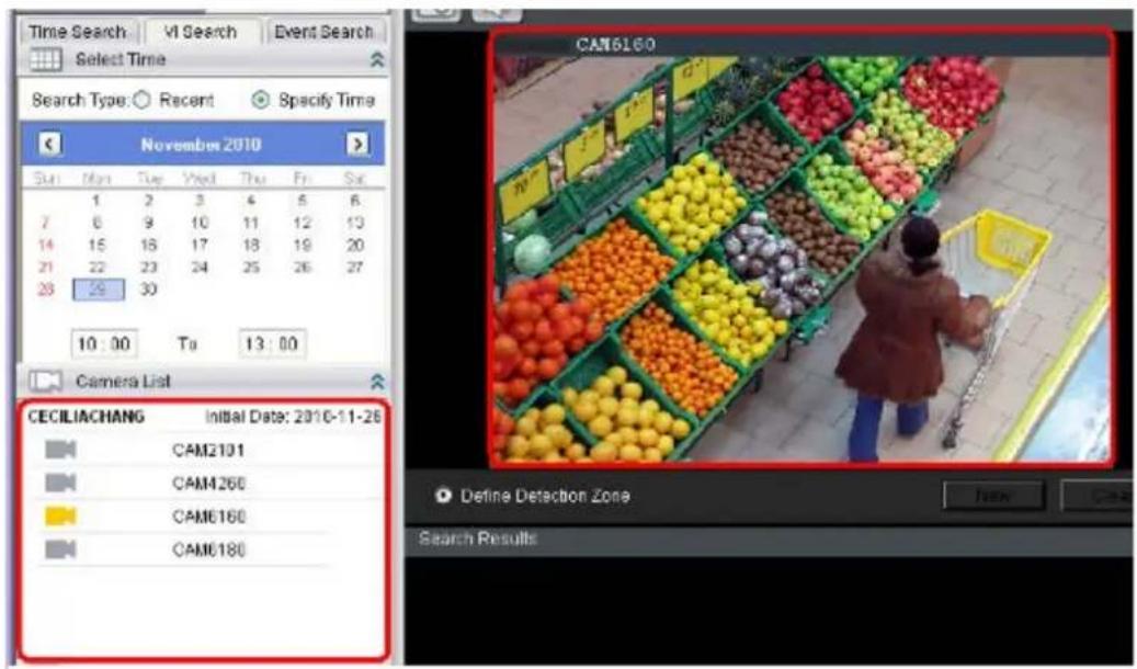
Select a camera to perform the VI search on by clicking its entry. This will display an initial thumbnail of the camera output.
Setting New Search Criteria
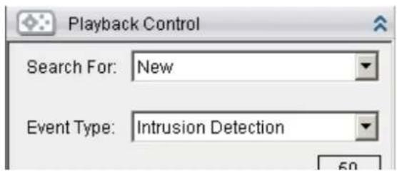
To create a New VI search:
- New in the playback control.
- Follow directions in the following sections to set up the VI search.
- Once the VI search is set up select either:
- Search All - Finds all events within the search range that trigger the VI set up.

- Search Step - Finds the first event that triggers the VI, then stops. The next event can be found by repeating the same search.
Click Search to begin the VI Search.
General Motion Detection
General motion detection involves detecting motion in specified areas. To set up General Motion Detection:
-
Select General Motion Detection from the Event Type dropdown.
-
New button to create a detection window. Up to 3 detection windows can be set for each camera. The current window will be highlighted with a red border.
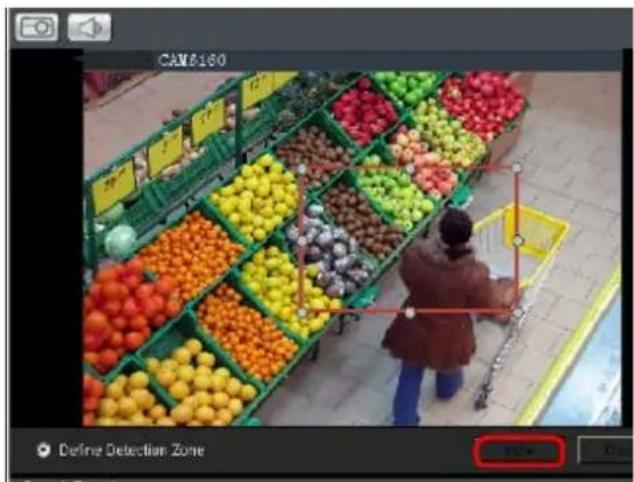
- Click and drag the white dots along window border of a window to resize or reshape the window. Click the interior of windows and hold to drag to reposition them. Move and resize windows until the area of detection is covered.

natural_image
Overhead view of a person shopping in front of a grocery store filled with colorful fruit displays (no visible text or signage)
natural_image
Overhead view of a person shopping in front of a grocery store filled with colorful fruit displays (no visible text or signage)- Adjust the sliders in the Playback Control section. (Settings will be applied to all existing windows)
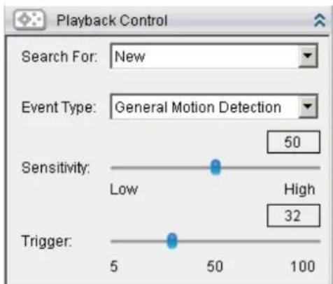
■ Sensitivity - Adjusts window sensitivity from 0 (low) to 100 (high).
- Trigger - Adjusts the amount of change allowed before and event is triggered.
Tampering Detection
Tampering detection involves using the software to determine when the camera has been improperly moved or redirected. To configure:
- Select Tampering Detection from the Event Type dropdown.
- Adjust the sliders:
■ Sensitivity - Adjusts window sensitivity from 0 (low) to 100 (high).
- Trigger - Adjusts the amount of change allowed before an event is triggered.
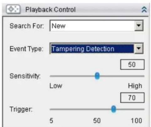
Intrusion Detection
Intrusion detection involves using the software to analyze the video feed and detect intrusion in specified areas. To configure:
- Select Intrusion Detection from the Event Type dropdown.
- Select Define Detection Zone and click the New button to create a new window. Up to 3 detection windows can be set for each camera. The current window will be highlighted with a red border.

- Click and drag the white dots along window border of a window to resize or reshape the window. Click the interior of windows and hold to drag to reposition them. Move and resize windows until the area of to be secured is covered.

natural_image
Overhead view of a person shopping in front of a grocery store filled with colorful fruit displays (no visible text or signage)
natural_image
A woman shopping in front of a grocery store filled with colorful fruit and vegetables (no visible text or signage)- Select Define Object and click the New button to create an object box.
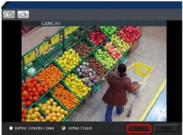
- Click and drag the white dots along the window border to resize it and define the minimum size of objects that will be detected.

natural_image
A woman shopping in front of a grocery store filled with colorful fruit and vegetables (no visible text or signage)
natural_image
Overhead view of a person shopping in front of a grocery store filled with colorful fruit displays (no visible text or signage)- Adjust the sliders in the Playback Control section. (Settings will be applied to all existing windows)
■ Sensitivity - Adjusts window sensitivity from 0 (low) to 100 (high).
- Duration (Msec) - Adjusts how much time between each check of the window for intrusions.
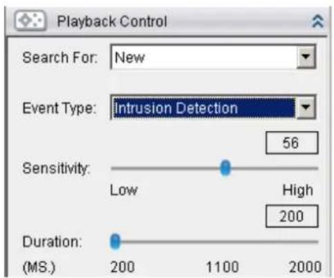
Missing Object Detection
Missing object detection involves using the software to analyze the video feed and detect missing objects larger than a certain size. To configure:
- Select Missing Object Detection from the Event Type dropdown.
- Select Define Detection Zone and click the New button to create a new window. Up to 3 detection windows can be set for each camera. The current window will be highlighted with a red border.

- Click and drag the white dots along window border of a window to resize or reshape the window. Click the interior of windows and hold to drag to reposition them. Move and resize windows until the area to be secured is covered.

natural_image
A person shopping in front of a colorful fruit market stall with green and yellow crates (no visible text or signage)
natural_image
Overhead view of a person shopping in front of a grocery store filled with colorful fruit displays (no visible text or signage)- Select Define Object and click the New button to create an object box.
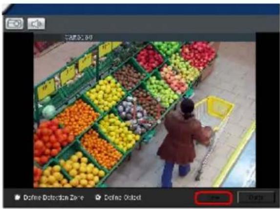
- Click and drag the white dots along the window border to resize it and define the minimum size of the object(s) that will be secured.

natural_image
A woman shopping in front of a grocery store filled with colorful fruit and vegetables (no visible text or signage)
natural_image
Overhead view of a person shopping in front of colorful fruit displays (no visible text or symbols)- Adjust the sliders in the Playback Control section. (Settings will be applied to all existing windows)
■ Sensitivity - Adjusts window sensitivity from 0 (low) to 100 (high).
- Duration (Sec) - Adjusts how much time an object is missing before an event is triggered.
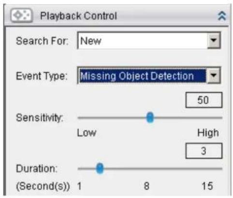
Foreign Object Detection
Foreign object detection involves using the software to analyze a video feed and detect objects that do not belong. To configure:
- Select Foreign Object Detection from the Event Type dropdown.
- Select Define Detection Zone and click the New button to create a new window. Up to 3 detection windows can be set for each camera. The current window will be highlighted with a red border.
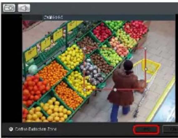
- Click and drag the white dots along window border of a window to resize or reshape the window. Click the interior of windows and hold to drag to reposition them. Move and resize windows until the area of detection is covered.

natural_image
A woman shopping in front of a supermarket filled with colorful fruit boxes (no visible text or signage)
natural_image
Overhead view of a person shopping in front of a grocery store filled with colorful fruit and vegetables (no visible text or signage)- Select Define Object and click the New button to create an object box.
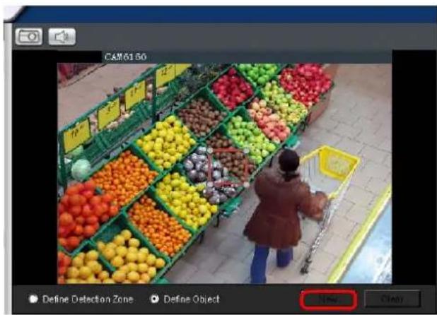
- Click and drag the white dots along the window border to resize it and define the minimum size of foreign objects that will be detected.

natural_image
A person shopping in front of a fruit market stall with colorful fruits and green baskets (no visible text or signage)
natural_image
A woman shopping in front of a fruit stall with colorful fruits and green baskets (no visible text or signage)- Adjust the sliders in the Playback Control section. (Settings will be applied to all existing windows)
■ Sensitivity - Adjusts window sensitivity from 0 (low) to 100 (high).
■ Duration (Sec) - Adjusts the amount of time before an object triggers an event.
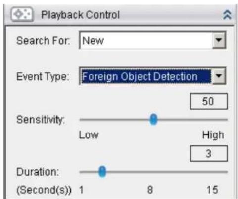
Forbidden Area Detection
Forbidden area detection involves using the software to analyze the video feed and immediately detect any object in specified areas. To configure:
-
Select Forbidden Area Detection from the Event Type dropdown.
-
Select Define Detection Zone and click the New button to create a new window. Up to 3 detection windows can be set for each camera. The current window will be highlighted with a red border.
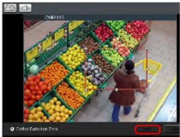
- Click and drag the white dots along window border of a window to resize or reshape the window. Click the interior of windows and hold to drag to reposition them. Move and resize windows until the forbidden area is covered.

natural_image
A woman shopping in front of a supermarket filled with colorful fruit displays (no visible text or signage)
natural_image
Person shopping in front of a fruit market stall with colorful crates (no visible text or signage)- Select Define Object and click the New button to create an object box.
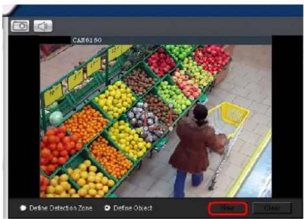
- Click and drag the white dots along the window border to resize it and define the minimum size of objects that will be detected.

natural_image
Overhead view of a person shopping in front of a grocery store filled with colorful fruit and vegetables (no visible text or signage)-
Adjust the sliders in the Playback Control section. (Settings will be applied to all existing windows)
-
Sensitivity – Adjusts window sensitivity from 0 (low) to 100 (high).
- Interval - Adjusts how much time between each check of the forbidden area.
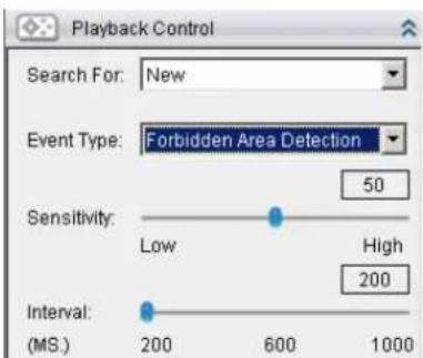
Virtual Fence
Virtual fence involves using the software to create a fence-crossing detection of the demanding object. To configure:
- Select Virtual Fence from the Event Type dropdown.
- Select Define Detection Zone and click the New button to create a new window. Up to 3 detection windows can be set for each camera. The current window will be highlighted with a one/two-way arrow (blue means "in", green means "out").
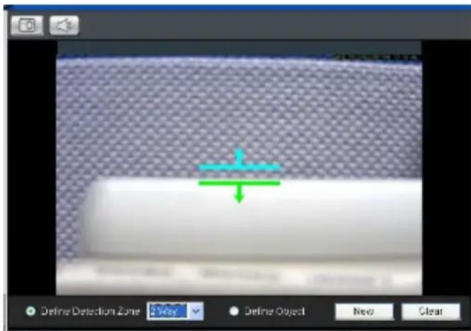
- Click and drag the white arrows along the window border around the one/two-way arrow to resize the space between the fences/adjust the length of the fences.
- Turn the window border with the orange arrow to change the directions of the fences.
- Select Define Object and click the New button to create an object box.
- Click and drag the white dots along the window border to resize it and define the minimum size of objects that will be detected.
- Adjust the sliders in the Playback Control section. (Settings will be applied to all existing windows)
■ Sensitivity - Adjusts window sensitivity from 0 (low) to 100 (high).
- Duration (Sec) – Adjusts how much time between each check for the fence-crossing.
Going Out Detection
Going Out detection involves using the software to analyze the video feed and immediately detect any object in specified areas. To configure:
-
Select Going Out Detection from the Event Type dropdown.
-
Select Define Detection Zone and click the New button to create a new window. Only 1 detection window can be set for each camera. The current window will be highlighted with a red border.
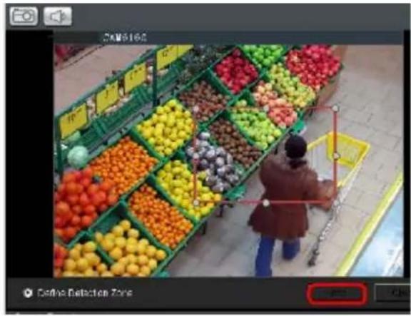
- Click and drag the white dots along window border of a window to resize or reshape the window. Click the interior of windows and hold to drag to reposition them. Move and resize windows until the Going Out boundary is done.

natural_image
A woman shopping in front of a fruit market stall with colorful fruit displays (no visible text or signage)
natural_image
Overhead view of a person shopping in front of a grocery store filled with colorful fruit displays (no visible text or signage)- Select Define Object and click the New button to create an object box.
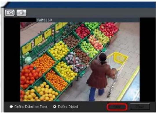
- Click and drag the white dots along the window border to resize it and define the minimum size of objects that will be detected.

natural_image
A woman shopping in front of a fruit market stall with colorful crates (no visible text or signage)
natural_image
A person shopping in front of a grocery store filled with colorful fruit and vegetables (no visible text or signage)-
Adjust the sliders in the Playback Control section. (Settings will be applied to all existing windows)
-
Sensitivity – Adjusts window sensitivity from 0 (low) to 100 (high).
- Interval - Adjusts how much time between each check of the forbidden area.
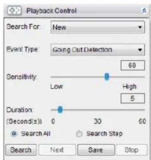
Tailgating Detection
Tailgating Detection involves using the software to create a fence-crossing detection of the demanding object. To configure:
- Select Tailgating Detection from the Event Type dropdown.
- Select Define Detection Zone and click the New button to create a new window. Only 1 detection window can be set for each camera.
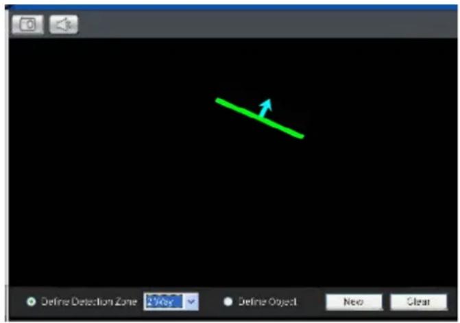
- Click and drag the arrow to adjust the position and direction.
- Select Define Object and click the New button to create an object box.
- Click and drag the white dots along the window border to resize it and define the minimum size of objects that will be detected.
-
Adjust the sliders in the Playback Control section. (Settings will be applied to all existing windows)
-
Sensitivity - Adjusts window sensitivity from 0 (low) to 100 (high).
- Duration (Sec) – Adjusts how much time between each check for the fence-crossing.
10.3.2. Saving/Retrieving a VI Search
Once the VI search is setup, you may save it by clicking the Save button. The system will prompt you for a name. Saved VI searches can also be retrieved using the Search for dropdown, or by clicking the Next button.
10.3.3. Using the Search Results
Selecting the Result
Search result thumbnail(s) will be displayed in the results box.
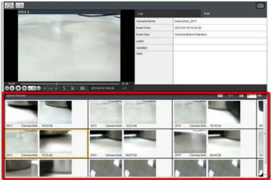
Clicking the thumbnail will select the detection instance. The following information fields are available for each instance:
| Log | Note | |
| Camera Name: | DAISYCHAN_CAM1301 | |
| Event Time: | 2012-02-20 13:43:23 | |
| Event Type: | General Motion Detection | |
| Label: | ||
| Updated: | ||
| Note: | ||
■ Camera Name - The camera used to capture the video.
Event Time - The time the event occurred.
Event Type – The type of VI detection that the event triggered.
Label - A user-defined label (optional).
- Updated - The last time the event was updated.
Note - A simple comment or note for the clip.
Result Playback
Once a result is selected by clicking on it, playback can be started by double clicking on the thumbnail. Alternatively, you may right-click the thumbnail and click Play. A ten minute clip containing the event will begin playing, with the start time synchronized with the start of the event.
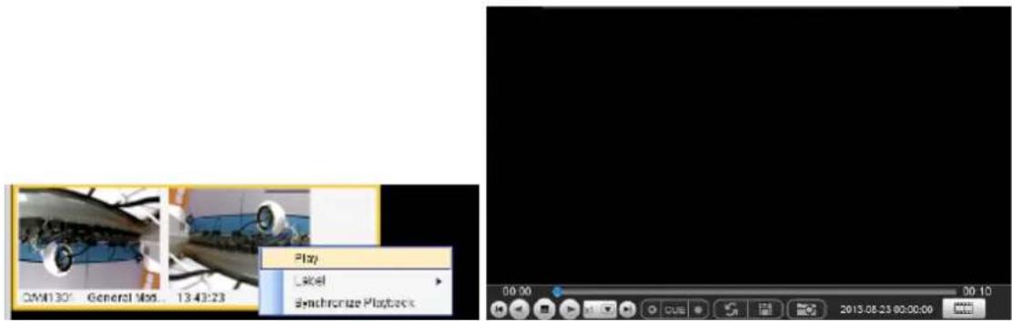
The following functions are available for playback:
 | Starts video playback. |
 | Reverses video playback. |
 | Stops video playback. |
 | Jumps to the next segment. |
 | Jumps to the previous segment. |
 | Clears the cue-in and cue-out markers. |
 | Set Cue-In marker for clip start |
 | Set Cue-Out marker for clip end |
 | Loop, continuous playback within Cue-In & Cue-Out |
 | Enable / Disenable loop. Loop to continuous playback within Cue-In & Cue-Out. |
 | Saves video clips/ Exports selected clips. |
 | Snapshot |
 | Real time mode |
 | Frame by frame mode |
 | Just key frame mode |
Playback Synchronization
Search results can be sent to the time-based playback window for comparison with other video streams using the Synchronize Playback function. This action will send the 10 minute segment containing the detected event to the time-based playback window.
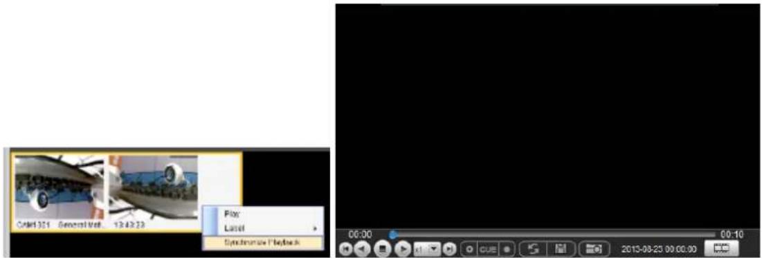
Capturing Screenshot
To capture a screenshot:
- Click the Capture button located in the button area.
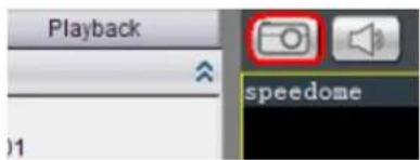
- In the Path field enter a file path and filename for the screenshot. Alternately, you may also click Browse and select a file path.
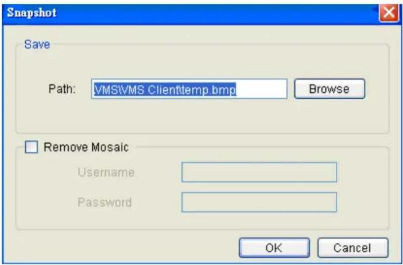
-
(Optional) You may click Remove Mosaic and enter a valid Username and Password to remove any privacy-mask mosaicing.
-
Click OK to save the screenshot.
Capturing Video Clip
To capture a video segment:
- Click the Cue In button, and place the marker at the start of the segment to be captured.
- Click the Cue Out button, and place the marker at the end of the segment to be captured.
- Click the Save Video Clip button located in the control area beside the Cue In and Cue Out buttons. A system popup will open prompting for a filename and location for the video clip.
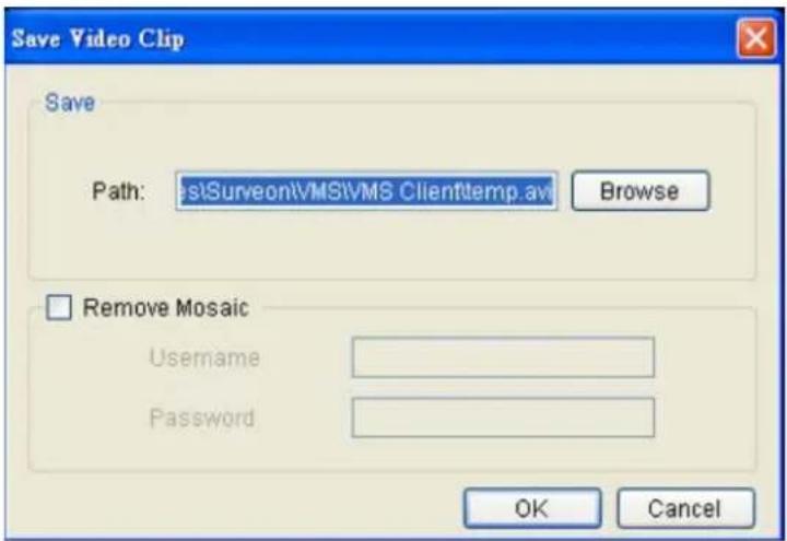
-
(Optional) Change the filename and file path. If you do not change the file details, the default save location for the video clip will be your installation path.
-
(Optional) You may click Remove Mosaic and enter a valid Username and Password to remove any privacy-mask mosaicing.
Logging and Noting
Clicking the Note tab beside the log entry will let you tag and note the search result for future references.
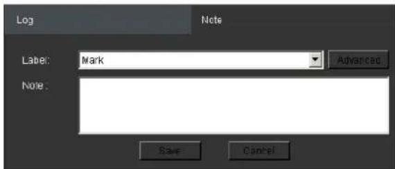
You may choose one of the following:
Label - Select one of the defined labels.
Note - A short description for the video clip.
Label Setup
Clicking Advanced from the note context will bring up the label setup menu. To add a label:
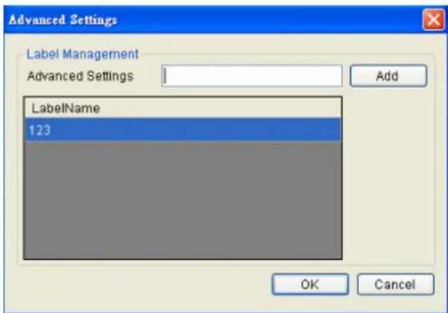
- Enter a name in the Advanced Settings field.
- Click Add. The new label will appear in the LabelName table. Future clips may be tagged with this label.
10.4. Event Search
An event search involves searching for multiple tagged events over one more cameras. To access Event search, click the Event Search tab in the Playback context.

10.4.1. Creating an Event Search
Time Selection
There are two types of time selections that can be made: Recent Time and Specified Time.
Recent Time
To perform a recent time search, click the Recent option in the time selection box. Choose one of the simple time choices to perform playback/search from that time period.
Specified Time
A specified time search can be selected by choosing the Specify Time option from the time selection box, and involves defining a time and date for the playback/ search.
Using the calendar select a date for search/ playback. For an event search, multiple dates can be selected by clicking on the calendar and dragging the cursor to select multiple dates. Multiple areas can be selected by pressing the control key and selecting additional dates.
Once a date or dates are selected, clicking on the boxes will allow you to specify a specific period to search/ playback in 10 minute increments.
Camera Selection
Once the search time range has been specified, a list of cameras with video recorded during the period specified will appear in the Camera List.
Select a camera to perform the event search on by clicking its entry. Multiple cameras can be selected for the search.
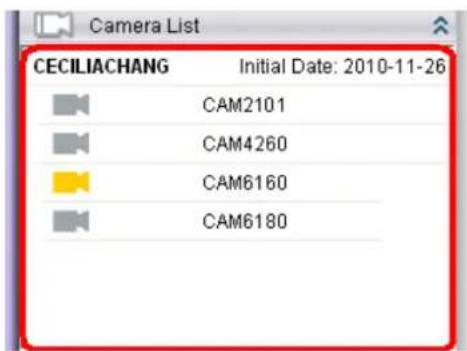
Setting Event Search Criteria
- Choose an Event Type and/or a Label to search for. Selecting Ignore will search for all labels.
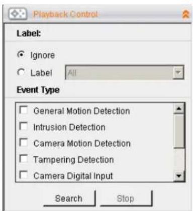
- Click Search to begin the search. Results will display in the Search Results panel.
10.4.2. Using the Search Results
Selecting the Result
Search result thumbnail(s) will be displayed in the results box.
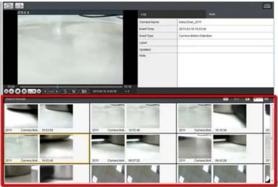
Clicking the thumbnail will select the detection instance.
The following information fields are available for each instance:
| Log | Note | |
| Camera Name: | DAISYCHAN_CAM1301 | |
| Event Time: | 2012-02-20 13:43:23 | |
| Event Type: | General Motion Detection | |
| Label: | ||
| Updated: | ||
| Note: | ||
-
Camera Name – The camera used to capture the video.
Event Time – The time the event occurred.
Event Type - The type of VI detection (if any) that the event triggered (optional).
Label - A user-defined label (optional). -
Updated - The last time the event was updated.
Note - A simple comment or note for the clip.
Result Playback
Once a result is selected by clicking on it, playback can be started by double clicking on the thumbnail. Alternatively, you may right-click the thumbnail and click Play. A ten minute clip containing the event will begin playing, with the start time synchronized with the start of the event.
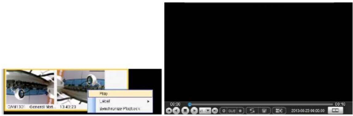
The following functions are available for playback:
 | Starts video playback. |
 | Reverses video playback. |
 | Stops video playback. |
 | Jumps to the next segment. |
 | Jumps to the previous segment. |
 | Clears the cue-in and cue-out markers. |
 | Set Cue-In marker for clip start |
 | Set Cue-Out marker for clip end |
 | Loop, continuous playback within Cue-In & Cue-Out |
 | Enable / Disenable loop. Loop to continuous playback within Cue-In & Cue-Out. |
 | Saves video clips/ Exports selected clips. |
 | Snapshot |
 | Real time mode |
 | Frame by frame mode |
 | Just key frame mode |
Playback Synchronization
Search results can be sent to the time-based playback window for comparison with other video streams using the Synchronize Playback function. This action will send the 10 minute segment containing the detected event to the time-based playback window.
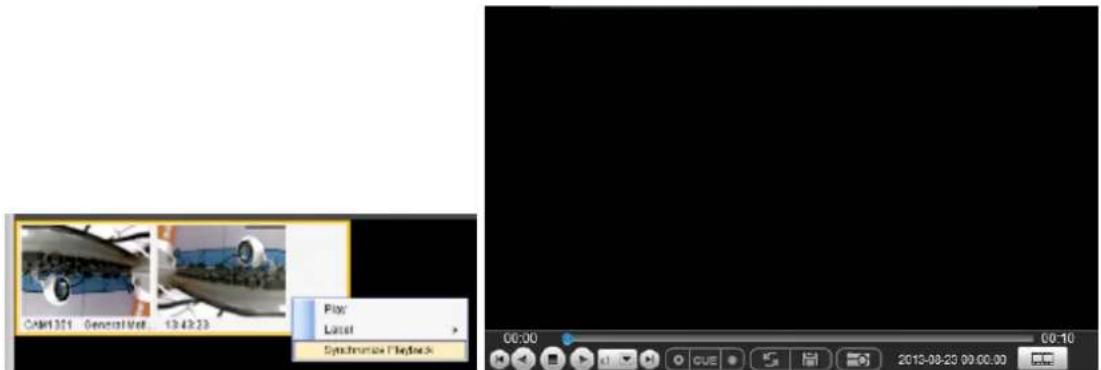
Capturing Screenshot
To capture a screenshot:
- Click the Capture button located in the button area.
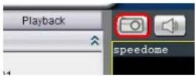
- In the Path field enter a file path and filename for the screenshot. Alternately, you may also click Browse and select a file path.
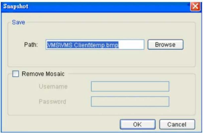
-
(Optional) You may click Remove Mosaic and enter a valid Username and Password to remove any privacy-mask mosaicing.
-
Click OK to save the screenshot.
Logging and Noting
Clicking the Note tab beside the log entry will let you tag and note the search result for future references.
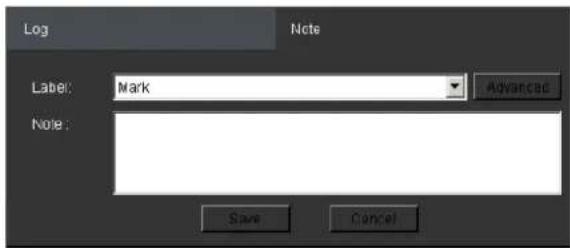
You may choose one of the following:
Label - Select one of the defined labels.
Note - A short description for the video clip.
Label Setup
Clicking Advanced from the note context will bring up the label setup menu.
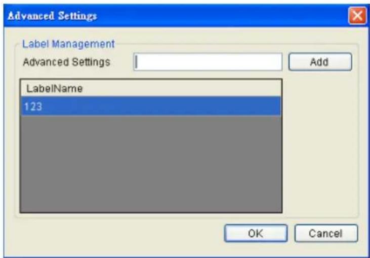
To add a label:
- Enter a name in the Advanced Settings field.
- Click Add. The new label will appear in the LabelName table. Future clips may be tagged with this label.
Chapter 12. Remote Web Client and SPhone Client for Simple Use (Optional)
For remote users, there are 3 methods for viewing.
- Remote Client: install Remote Client on remote PCs for live view and playback.
- Web Client: use the browser IE (Internet Explorer) and input the IP address of the camera for live view and playback.
- Mobile Client: install the Sphone Client app on iOS or Android mobile devices for basic live viewing.
12.1. Starting the Web Client
Launch Microsoft Internet Explorer 7.0 (or above) and enter your VMS Server IP address + "/webclient" in your web browser's URL location, e.g. http://172.18.6.9/webclient to download the Web Client application.
Note: Please check the web server settings in the VMS console first.
After the Web Client installation is done, a login window will pop up.
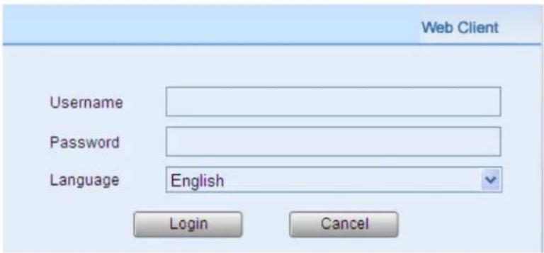
- Username - The username for the domain. Default username is admin.
- Password - The password for the domain. Default password is admin.
Language -Options for the interface languages.
Click Login after the username and password are entered.
After logging in, the live view page will be displayed on the web browser.
12.1.1. Checking the Software Version
Users can see the software version at the lower left corner of the window after logging in.
12.1.2. Use of 1x/4x views
Users have the option of viewing up to 4 recorded video streams at once, or just one stream at a time. Either of these options can be chosen by clicking on corresponding button in the button area above the main view screen. In both cases functionality and operation is the same.

12.1.3. PTZ Control
Cameras equipped with Pan-Tilt-Zoom functionality can be controlled directly within the Web Client. These controls can be found in the PTZ Control window within the live view screen.
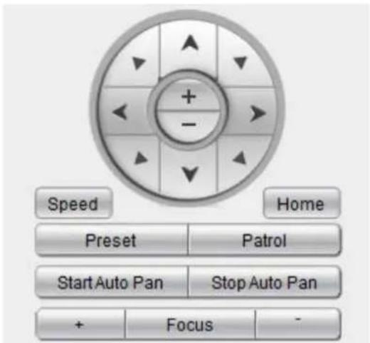
12.1.4. Playback Settings
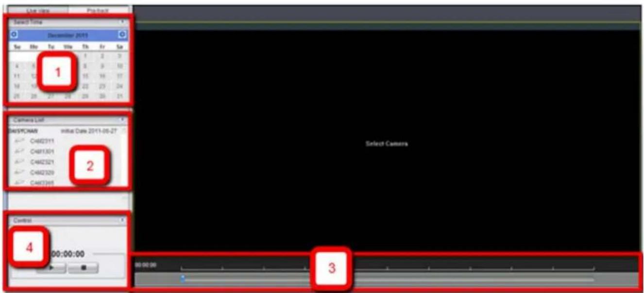
Users can select the (1) time and (2) camera, and then use the (3) time line and (4) playback control panel to do the playback.
Note: For more details of PTZ Control and Playback Control, please refer to PTZ Control and Playback sections in this chapter.
12.2. Installing and Starting the SPhone Client on iOS Devices
12.2.1. Installing the SPhone Client (Optional)
Download the SPhone Client from App Store on the iPhone desktop.
12.2.2. Starting the SPhone Client
Note: Please check the web server settings in the VMS console first.
After the SPhone Client installation is done, a login window will pop up.
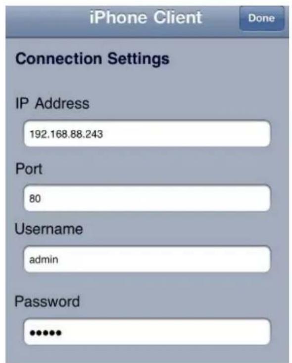
IP Address: The IP address for the VMS/ NVR Server.
Port: The login port for SPhone Client. Default port number is 80.
Note: The port number should be the same with the web server port.
- Username - The username for the domain. Default username is admin.
- Password - The password for the domain. Default password is admin.
Click Done button on the upper right corner after the port, username and password are entered.
12.2.3. Checking the Software Version
Users can see the software version at the lower right corner of the window after logging in..
12.2.4. Live View/Playback on the SPhone Client
You can use live view and playback functionalities through SPhone Client:
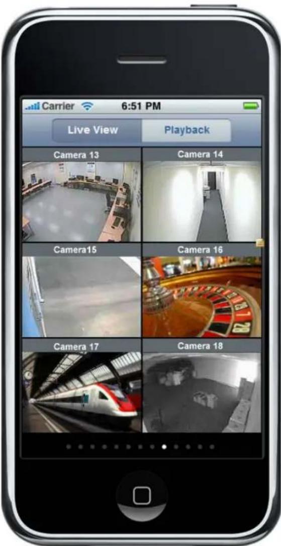
At most 6-channel live view can be displayed in the same page.
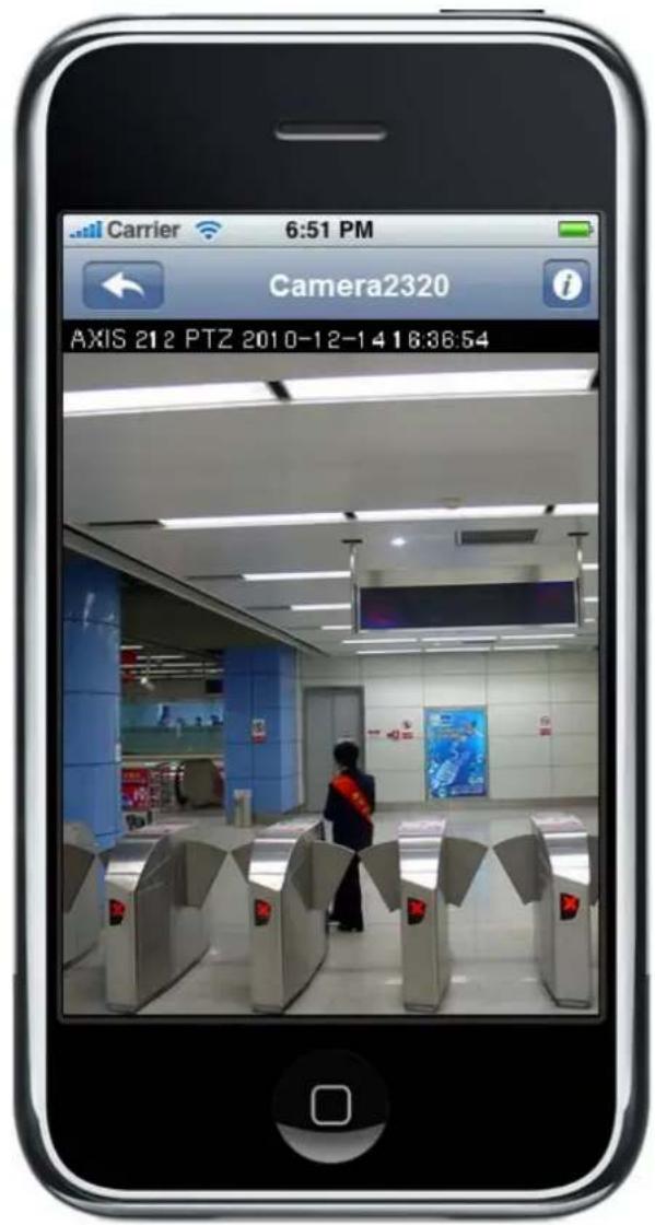
Press the icon at the upper left to jump to the previous page or press
the button on the phone to go to the next page.
The i icon beside each camera name can be used to check the detailed information of each camera as follows.
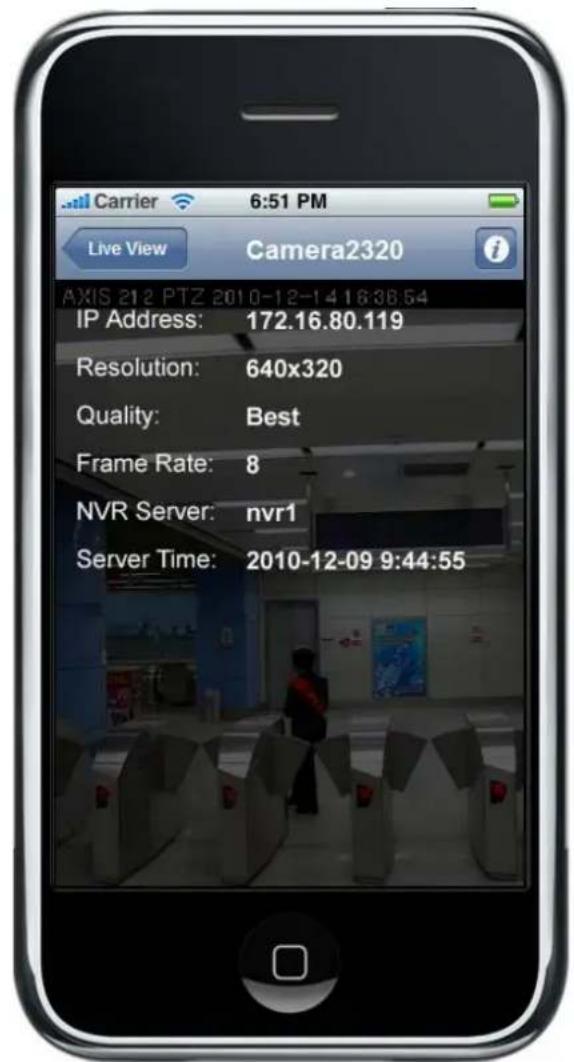
IP Address: The IP address for the VMS/ SMR Server
■ Resolution: The video resolution of the camera
Quality: The video quality of the camera
Frame Rate : The frame rate of the camera
NVR Server: The VMS/ SMR Server name
Server Time
12.3. Installing and Starting the SPhone Client on Android Devices
12.3.1. Installing the SPhone Client (Optional)
Download the SPhone Client from App Store on the Android phone desktop.
12.3.2. Starting the SPhone Client
Note: Please check the web server settings in the VMS console first.
After the SPhone Client installation is done, a login window will pop up.
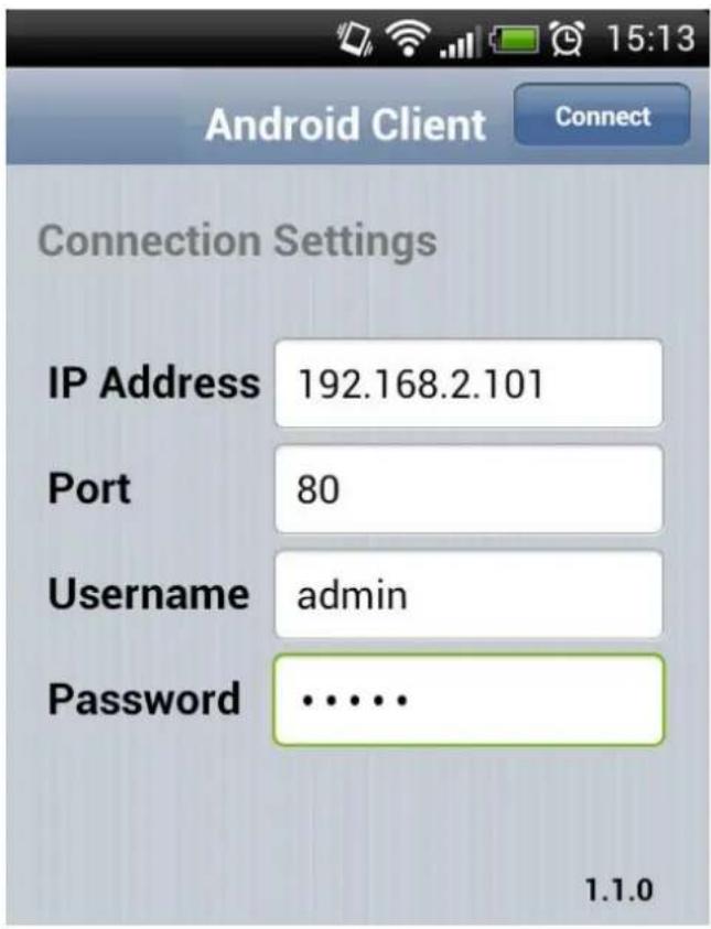
IP Address: The IP address for the VMS/ NVR Server.
Port: The login port for SPhone Client. Default port number is 80.
Note: The port number should be the same with the web server port.
- Username - The username for the domain. Default username is admin.
- Password - The password for the domain. Default password is admin.
Click Done button on the upper right corner after the port, username and password are entered.
12.3.3. Checking the Software Version
Users can see the software version at the lower right corner of the window after logging in.
12.3.4. Live View on the SPhone Client
You can use basic live view functionalities through SPhone Client:
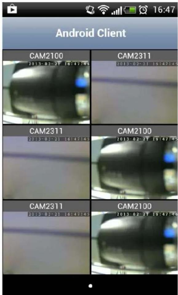
At most 6-channel live view can be displayed in the same page.
Press the 📋 icon at the upper left to jump to the previous page or press the

button on the phone to go to the next page.

The icon beside each camera name can be used to check the detailed information of each camera as follows.
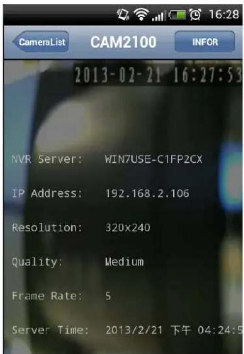
NVR Server: The VMS/ SMR Server name
IP Address: The IP address for the VMS/ SMR Server
■ Resolution: The video resolution of the camera
■ Quality: The video quality of the camera
Frame Rate : The frame rate of the camera
Server Time
Chapter 13. System Setup
13.1. Home Page
In the VMS system, the management scope is referred to as a "Domain." Managed servers are all part of a "Domain" with uniform access rules and a single configuration point. For basic local domains this configuration points are the VMS Console.
13.1.1. Entering the Home Page - VMS Server
Select Setup Button on the menu bar.
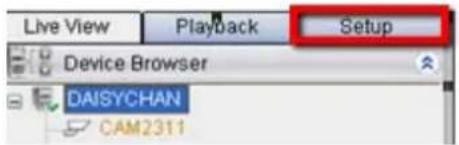
The home page appears, listing shortcuts to commonly used functionalities, system status, and recent events.
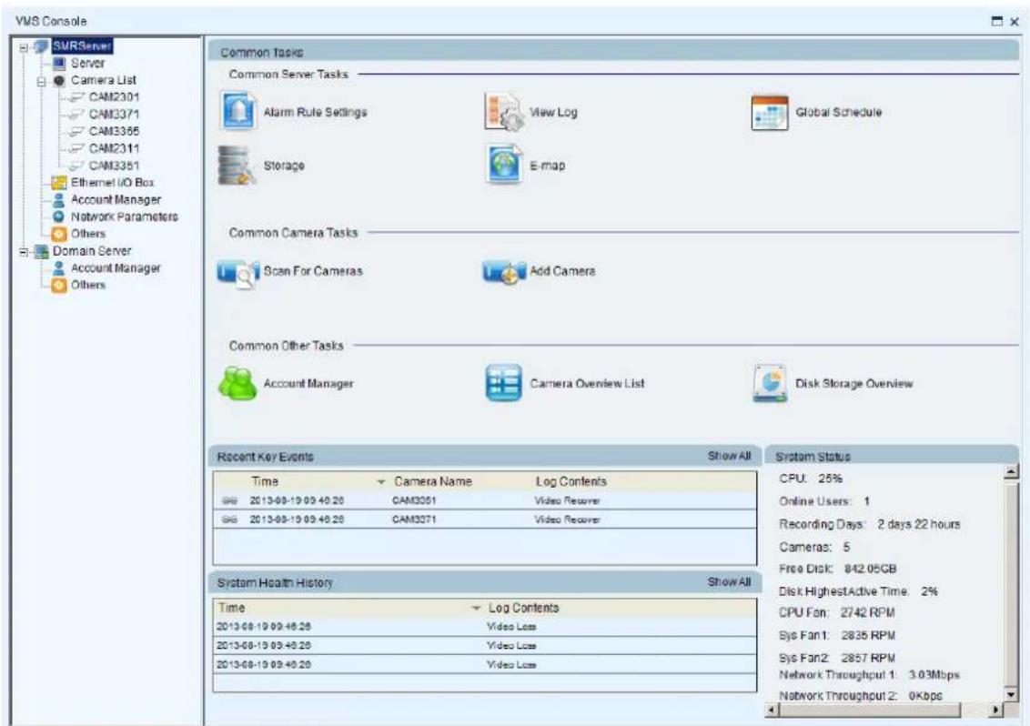
Here are the screen elements:
Common Server Tasks
Lists shortcuts to frequently accessed server functionalities.
Alarm Rule Settings
In the alarm rule settings, you can combine the alarm trigger conditions with action items such as event notification, video recording, and/or camera movements. See Alarm Rules for more details.
View Log
The Event Log displays the camera the alarm occurred on, the date, the alarm type, and if applicable a link to the live-view feed of the camera. See Alarms View and Notification > Live View Event Log for more details.
Global Schedule
A global schedule can be created to apply to an entire Server. See Scheduling Recording > Global Scheduling for more details.
Storage
Opens the Storage Manager that allows you to configure storage settings. See Server Settings > Storage Management for more details.
E-map
When alarms occur, an administrator can quickly locate where the alarms took place using an E-map. See E-Maps for more details.
Common Camera Tasks
Lists shortcuts to frequently accessed camera functionalities.
Scan for Cameras
Allows you to scan cameras automatically. See Adding Cameras > Automatic Scan for Cameras for more details.
Add Cameras
Allows you to add cameras manually. See Adding Cameras > Manually Adding Cameras for more details.
Common Other Tasks
Lists shortcuts to frequently accessed system tasks.
Account Manager
Allows you to manage user accounts. See Account Manager for more details.
Camera Overview List
Shows the cameras added and their status.
| Camera Overview List | ||||||
| Camera Name | IP Address | MAC Address | Resolution | FPS | Bit Rate (mbps) | Status |
| CAM2321 | 172.18.6 123 | 00D0236009E5 | 1080P(1920x1080) | 25 | 6 Mbps | Online |
Disk Storage Overview
Shows information about the hard disks.
| Disk Volume(GB) | Total Disk Size(GB) | Video Recordings(GB) | Other Data(GB) | Free Space(GB) | Status |
| C | 3.5 | 0 | 3.5 | 0 | Normal |
| D | 0.11 | 0 | 0.11 | 0 | Normal |
Recent Key Events
Lists recent important system events. To view all system events, click Show All at the top right corner. The Event Log will appear. See Alarms View and Notification > Live View Event Log for more details.
System Health History
Lists the summary of recent user access. To view all history, click Show All at the top right corner.
System Status
Shows the status of system components.
13.1.2. Entering the Home Page - Local Domain
Select Domain Server from the side bar. The home page appears, listing shortcuts to commonly used functionalities and system status.
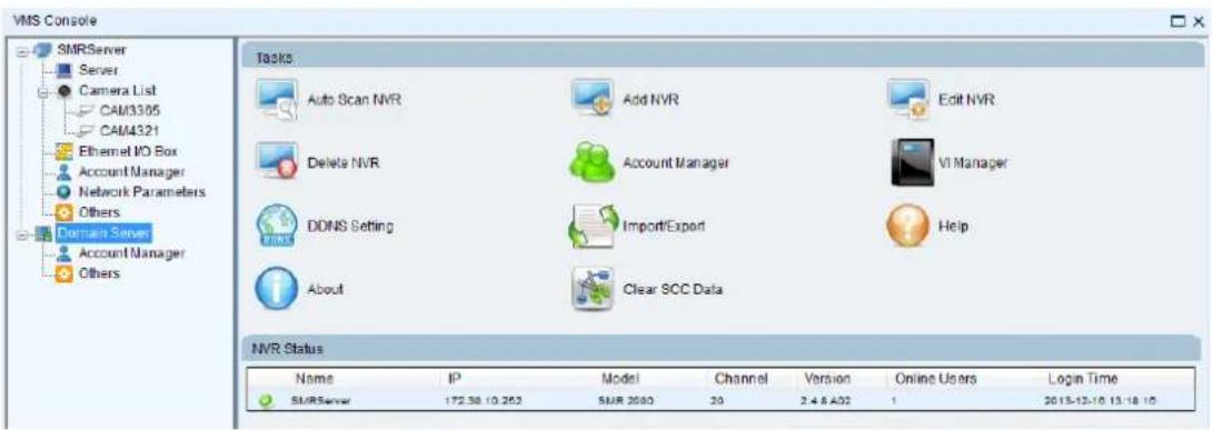
Here are the screen elements:
Tasks
Lists shortcuts to frequently accessed server functionalities.
Auto Scan NVR
Scans for the existing NVR Servers.
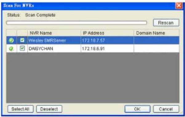
Add NVR
NVR Server can be added by entering the Server IP.
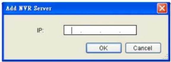
Edit NVR
Users can change both the setting of the stream port and the IP address by editing the Server.
Delete NVR
The added NVR Server can be deleted.
Account Manager
Account management for the domain can be performed under the Account Manager > Account List node. Under this dialog, you may add, delete, and edit domain users. See Account Manager for more details.
VI Manager
The VI server list can be managed in the VI Manager node in the Server. See Server Setup > Other Tasks > VI Manager for more details.
DDNS Setting
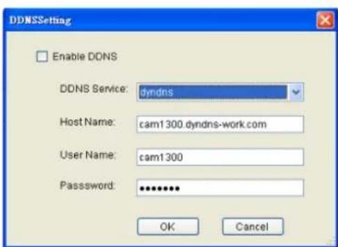
DDNS (Dynamic Domain Name Server) is a protocol that enables the camera to maintain a static connection address, even when its IP changes. Access using this feature is disabled by default.
Connecting using DDNS requires registration on third-party websites for DDNS services. Select desired DDNS service website, check the Enable DDNS option, and fill in valid user name and password. You can then access the camera through the registered domain name.
Import/ Export
Configuration/ setup files can be imported/ exported to the server. See Server Setup > Other Tasks > Import/ Export or Other Parameters > Other Tasks > Import/ Export for more details
Help
Allows you to access the VMS User Manual.
About
Allows you to view server and client information. See Server Basic Functions > Viewing Server and Client Information for more details.
Clear SCC Data
Allows you to clear the SCC / VMS data on the Domain Server.
NVR Status
Shows the status of the NVR Server.
13.2. Server Setup
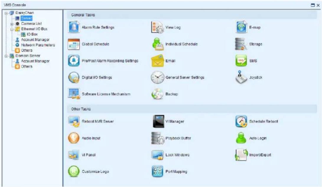
13.2.1. General Tasks
Here you can access shortcuts for general server settings.
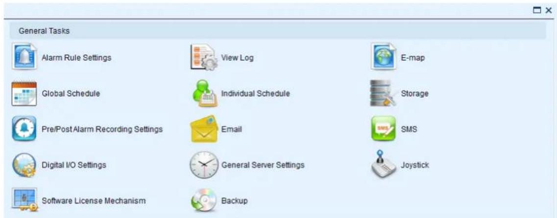
Alarm Rule Settings
In the alarm rule settings, you can combine the alarm trigger conditions with action items such as event notification, video recording, and/or camera movements. See Alarm Rules for more details.
View Log
The Event Log displays the camera the alarm occurred on, the date, the alarm type, and if applicable a link to the live-view feed of the camera. See Alarms View and Notification > Live View Event Log for more details.
E-Map
When alarms occur, an administrator can quickly locate where the alarms took place using an E-map. See E-Maps for more details.
Global Schedule
A global schedule can be created to apply to an entire Server. See Scheduling Recording > Global Scheduling for more details.
Individual Schedule
Individual schedules, which take precedence over the global schedule, can be set for each camera. See Scheduling Recording > Individual Scheduling for more details.
Storage
Opens the Storage Manager that allows you to configure storage settings. See Server Settings > Storage Management for more details.
Pre/Post Alarm Recording Settings
The Server can trace back and preserve video/images from several minutes before and after the occurrence of an alarm. See Server Settings > Pre/Post Alarm Recording Settings for more details.
When the alarm is triggered, an E-Mail will be sent. See Alarm Rules> Alarm Actions > Email for more details.
SMS
Configures the SMS setting. See Server Settings > To perform Notification Setting for more details.
Digital I/O Settings
Allows you to configure digital I/O port settings.
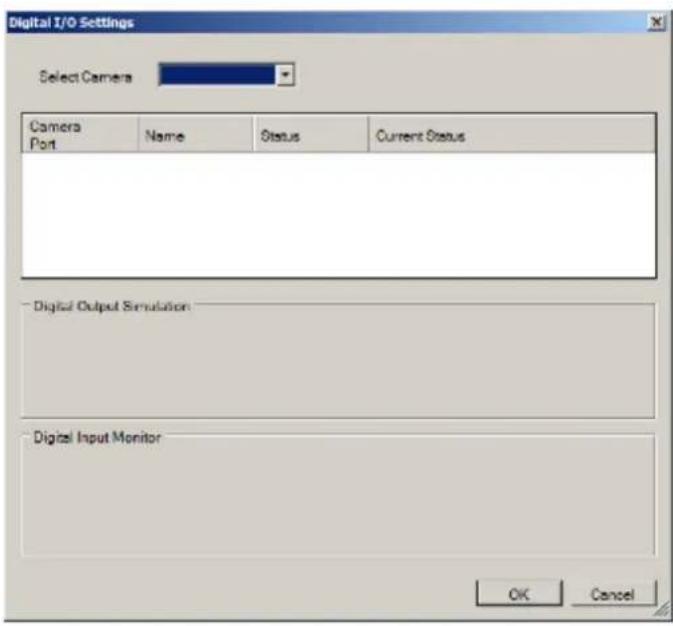
Genera Server Settings
Involves configuring both storage and server time settings. See Server Settings > General Server Settings for more details.
Joystick
CH Products IP Desktop USB Joystick is supported for PTZ camera control. Connect the joystick controller to the USB port. The Joystick Settings Window will prompt after clicking Joystick. In this window, functions of each button are listed.
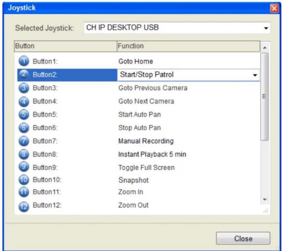
| Button Number | Function |
| 1 | Resets all the settings, including page auto-flipping and different screen divisions. |
| 2 Switches on/off | the functionality of switching between preset viewpoints. |
| 3 | Goes to the view of the previous camera. |
| 4 | Goes to the view of the next camera. |
| 5 | Starts auto pan. |
| 6. | Stops auto pan. |
| 7 | Manually records the video streams. |
| 8 | Pops up an instant playback for five minutes. |
| 9 | Brings up the full screen view. |
| 10 | Captures a snapshot. |
| 11 | Increase the zoom distance. |
| 12 | Decrease the zoom distance. |
You may reset the functions by choosing within the dropdown list.
Software License Mechanism (For Local Client Only)
Extra supported channels can be added by purchasing licenses.
- Click Browse under Information Storage Address, and enter a file name for exporting the existing channel information.
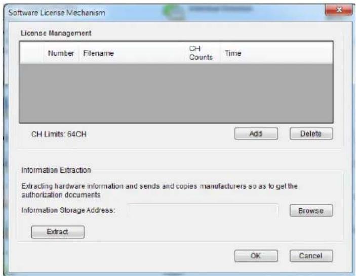
- Click Extract.
- Send the file (xxx.info) to Surveon's website
- After receiving the license file, import it by clicking Add.
- Check under the domain server to make sure if the channels are added successfully.
Backup (For Local Client Only)
- The video recording can be backed up. Set the time, select the camera, and choose the saving path for the backup files.
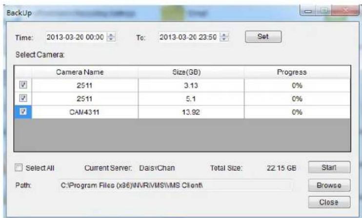
12.2.2. Other Tasks
Here you can access shortcuts for advanced server settings.
Other Tasks

Reboot NVR Server

VI Manager

Schedule Reboot

Audio Input

Playback Camera List Setting

Playback Buffer

Auto Login

VI Panel

Lock Windows

Advance View Explorer

Import/Export

Customize Logo

Port Mapping
Reboot NVR Server
The Server can be configured to perform a scheduled restart, daily or on a certain day of the week. Due to the trend of Windows performance degradation over time, we recommend that a reboot be performed at least once a week. This function can be found in the Auto Reboot node of the Server.
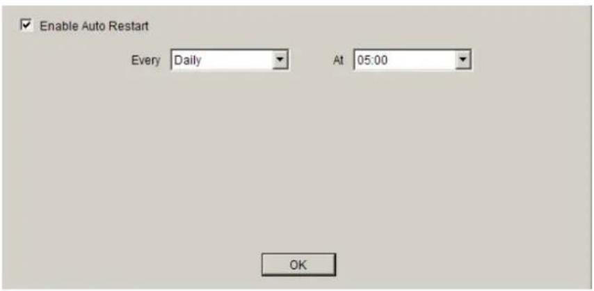
To configure an auto restart in this menu:
- Select the Enable Auto Restart checkbox.
- From the Every dropdown choose a day which you want to schedule an automatic restart. Options include weekly (Monday - Sunday) or Daily restarts.
- From the At dropdown, choose the hour which you want to perform the restart. Options include every hour of the day.
- Click the OK button to save your settings.
VI Manager
When a Video-Intelligent function is performed on the Server, the Server will contact a VI server to perform the computation for the VI function. The VI server list can be managed in the VI Manager node in the Server. In this dialog existing server IPs and ports can be viewed, and the user can choose to add or remove servers from the list.
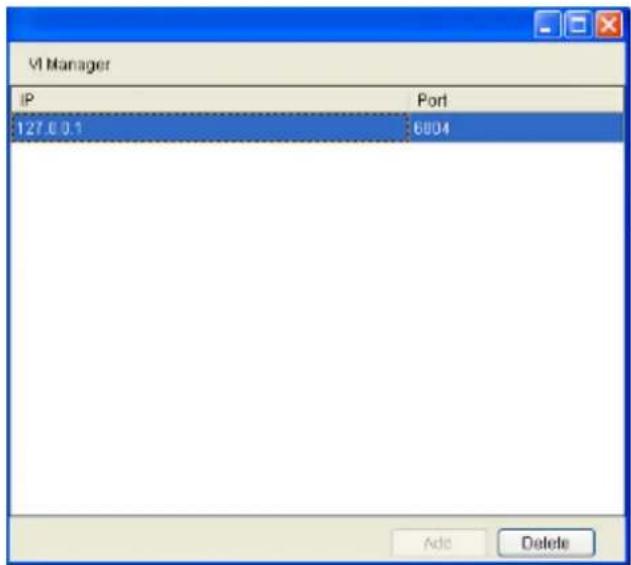
Note: At least one VI server must be configured on the system in order to successfully perform VI functions.
Adding a VI Server
To add a VI server to the server list in this dialog:
- Click the Add button, the server will respond with a VI form.
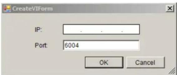
-
Fill in the IP address for the new VI server in the IP field.
-
Unless a specific port is desired and configured, leave the Port field default value, 6004.
-
Click OK to add the server. The server will be added to the VI server list.
Deleting a VI Server
To remove a VI server to the server list in this dialog:
-
Highlight the listing of the server you wish to remove.
-
Click the Delete button, the server will be removed from the server list.
Schedule Reboot
The client can be setup to automatically restart the client or the computer.
To configure the auto-reboot function:
-
From the client Schedule Reboot popup, check the Reboot box.
-
Select either Reboot Client to schedule a client restart, or System Restart? to schedule a windows restart.
-
From the Every dropdown, choose the day that you want to schedule restarts, or you may choose to restart every day.
-
From the At dropdown, choose the scheduled restart time.
Note: Auto-Login should be configured with Auto-restart or you will lose functionality until a user can be logged-in.
Audio Input
There are two choices available for audio channel selection. These two are selected using the Primary Audio Channel check box. If checked, the client will automatically use the audio feed from the selected/highlighted camera during live view.
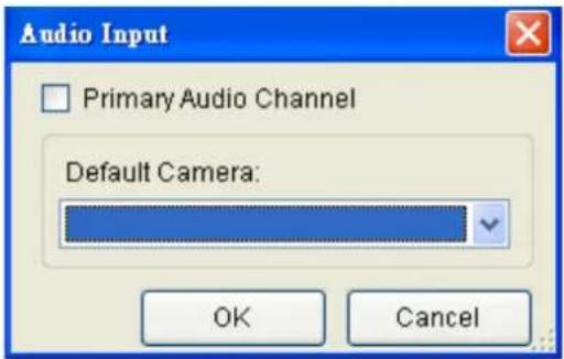
Unchecking the box will allow you to select a camera from the Default Camera drop-down. This camera will provide the audio feed no matter which channel is selected in live-view.
Playback Camera List Setting
Playback camera list can be from Live View or from the recording.
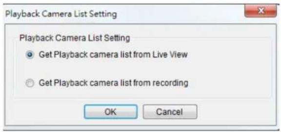
Playback Buffer
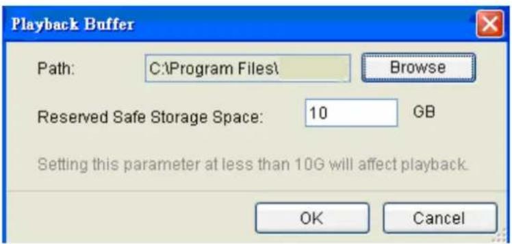
The Playback Buffer is used for downloading video recordings before the playback. The reserved safe storage space should be at least 10 GB.
Auto Login
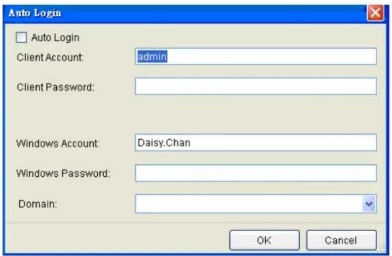
The client can be setup to automatically login after a crash or on startup.
To configure the auto-login function:
- From the client general settings popup, check the Auto Login box.
- If you want to automatically login to the client, enter the following information:
■ Client Account - The client account name.
- Client Password – The client password.
- If you want to automatically log into windows after a restart enter the following information:
Windows Account - The Windows account name.
Windows Password - The Windows password.
- Domain – The login domain.
VI Panel
The VMS can be configured to display windows in either 16:9 or 4:3 aspect ratios. To switch between these two, click VI Panel.
Lock Windows
The Video Panels can be locked in a certain configuration by clicking Lock Windows.
Import/Export
The following types of configuration/ setup files can be imported/ exported to the Server:
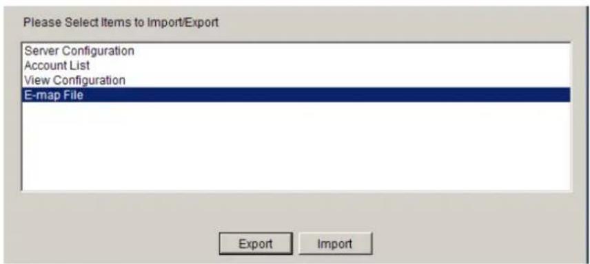
Server Configuration
Account List
View Configuration
E-map File
Importing Parameters
To import parameters into the Server:
- Select the item that you wish to import by clicking on the item type.
- Click the Import button. A windows explorer dialog will appear.
- Select the file to import from the file explorer, and click Open to import the file.
- Click OK to confirm import. The Server will require a restart before imported configurations and files are applied.
Exporting Parameters
To export parameters into the Server:
- Select the item that you wish to export by clicking on the item type.
- Click the Export button. A windows explorer dialog will appear.
- Input a filename and select the export path in the file explorer, and click Save to export the file.
Customize Logo
Allows users to change the logo of the Client by themselves.
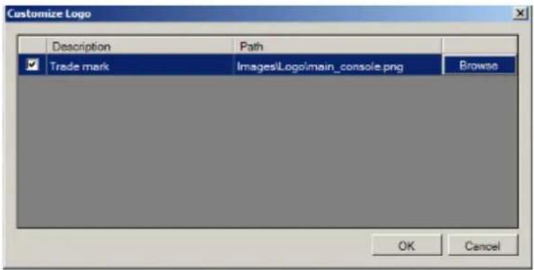
Note: The recommended size for the logo pictures is 280X52, in png format.
Router Port Mapping
Router Port Mapping for VMS/NVR Server. See Port Forwarding > Port Forwarding for Accessing VMS Server for more details.
13.3. Camera Setup
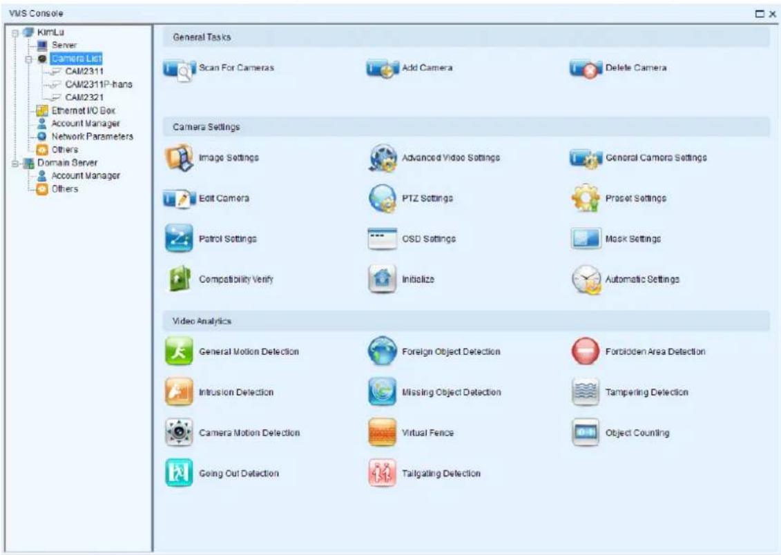
13.3.1. General Tasks
Here you can access shortcuts for general camera settings.
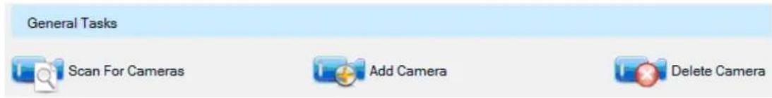
Scan for Cameras
Allows you to scan cameras automatically. See Adding Cameras > Automatic Scan for Cameras for more details.
Add Cameras
Allows you to add cameras manually. See Adding Cameras > Manually Adding Cameras for more details.
Delete Camera
Allows you to delete cameras manually. See Deleting a Camera for more details.
13.3.2. Camera Settings
Here you can access shortcuts for general camera settings.
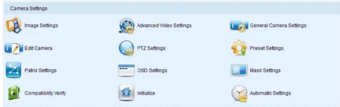
Image Settings
Allows you to adjust camera image settings. See Camera Image and Quality Settings > Camera Image Settings for more details.
Advanced Video Settings
Allows you to adjust video image parameters. See Camera Image and Quality Settings > Advanced Video Settings for more details.
General Camera Settings
Camera general settings include network connectivity settings, as well as basic camera name, description and icon settings. See Camera General Settings > General Settings for more details.
Edit Camera
In certain situations it may be necessary to change the Vendor or Model information for the camera. See Camera General Settings > Changing the Camera Model and Vendor for more details.
PTZ Settings
The PTZ settings deal with the software PTZ control panel. These settings adjust how much the camera will pan, tilt, zoom, and focus with each control panel input. See PTZ Settings > PTZ Settings for more details.
Preset Settings
Certain preset pan/tilt/zoom values can be saved in order to move the camera quickly to a point of interest. See PTZ Settings > PTZ Preset Settings for more details.
Patrol Settings
In cameras with PTZ functionality, one camera can be used to survey a large area. This can be done automatically using the patrol functionality. See PTZ Controls > Patrol for more details.
OSD Settings
On cameras with OSD capabilities, these capabilities can be configured within the server. See Camera General Settings > OSD Settings for more details.
Compatibility Verify
Check the compatibility of other connecting device.
Initialize
Restores initial settings of the camera. See Initializing a Camera for more details.
Automatic Settings
Camera time can be synchronized with the server. See Camera Settings for more details.
13.3.3. Video Analytics
Here you can access shortcuts for VI functions.
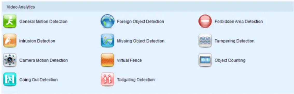
General Motion Detection
General motion detection involves using the software to analyze the video feed and detect motion in specified areas. See Camera VI Detection Settings > General Motion Detection for more details.
Foreign Object Detection
Foreign object detection involves using the software to analyze a video feed and detect objects that do not belong. See Camera VI Detection Settings > Foreign Object Detection for more details.
Forbidden Area Detection
Forbidden area detection involves using the software to analyze the video feed and immediately detect any object in specified areas. See Camera VI Detection Settings > Forbidden Area Detection for more details.
Intrusion Detection
Intrusion detection involves using the software to analyze the video feed and detect intrusion in specified areas. See Camera VI Detection Settings > Intrusion Detection for more details.
Missing Object Detection
Missing object detection involves using the software to analyze the video feed and detect missing objects larger than a certain size. See Camera VI Detection Settings > Missing Object Detection for more details.
Tampering Detection
Tampering detection involves using the software to determine when the camera has been improperly moved or redirected. See Camera VI Detection Settings >Tampering Detection for more details.
Camera Motion Detection
Camera motion detection involves using the camera hardware to analyze the video feed and detect motion in specified areas. See Camera VI Detection Settings > Camera Motion Detection for more details.
Virtual Fence
Virtual fence involves using the software to create a fence-crossing detection of the demanding object. See Camera VI Detection Settings > Virtual Fence for more details.
Object Counting
Object counting involves using the camera to count demanding object crossing the fences. See Camera VI Detection Settings > Object Counting for more details.
Going Out Detection
Camera motion detection involves using the camera hardware to analyze the video feed and detect motion in specified areas. See Camera VI Detection Settings > Going Out Detection for more details.
Tailgating Detection
Camera motion detection involves using the camera hardware to analyze the video feed and detect motion in specified areas. See Camera VI Detection Settings > Tailgating Detection for more details.
13.4. Ethernet I/O Box
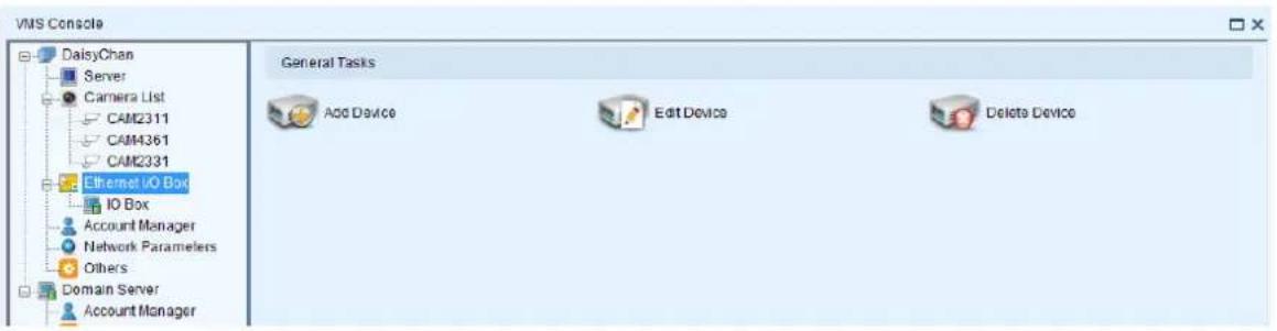
13.4.1. General Tasks
Here you can access shortcuts for general I/O box settings.
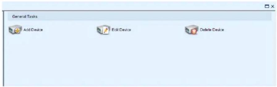
Add Device
Allows you to add Ethernet I/O box to the server.
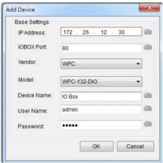
IP Address: The default IP for the I/O box, which is 192.168.0.100.
I/ O Box Port: 80.
Model: WPC-132-DIO.
■ Device Name: Enter the device name as you like.
■ User Name: Same with VMS username, which is always admin.
■ Password: Same with the password for VMS login.
After the I/O box is added successfully, it will appear on the device list.
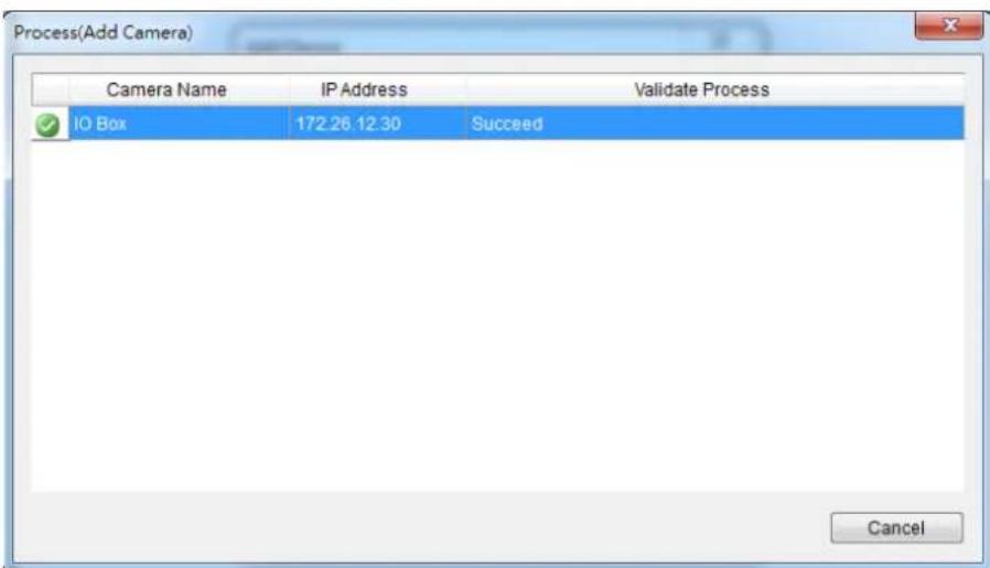
Go to Alarm Rule Setting, and set Senor Input and Relay Output.
Choose the input/output port numbers.
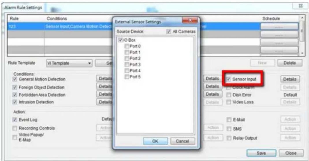
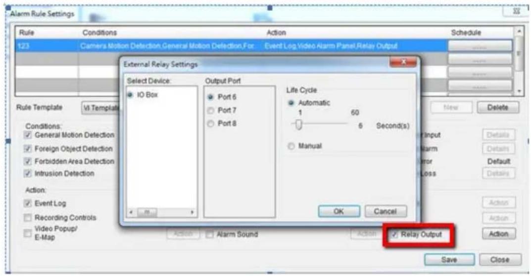
Edit Device
Allows you to edit the added I/O box.
Delete Device
Allows you to delete the added I/O box.
13.5. Account Manager
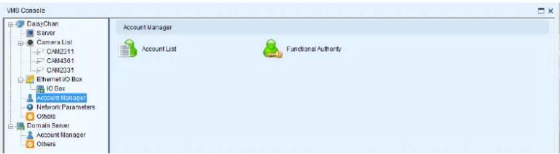
13.5.1. Account List
Account management for the domain can be performed under the Account Manager > Account List node in the VMS Console. Under this dialog, you may add, delete, and edit domain users.
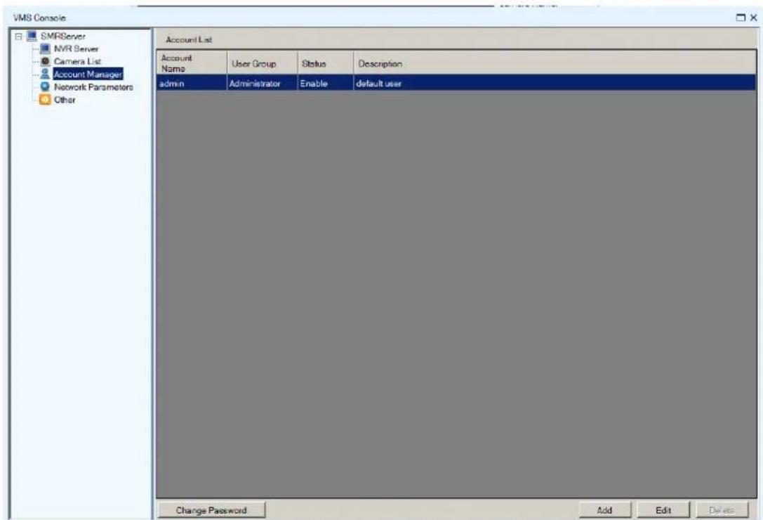
The Account List provides the following information about each account:
■ Account Name
■ User Group - Type for this user.
Status - This shows if the user is disabled or enabled.
■ Description – A simple description of the user.
Adding an Account
To add an account to the domain:
- Access the Account List node in the VMS Console.
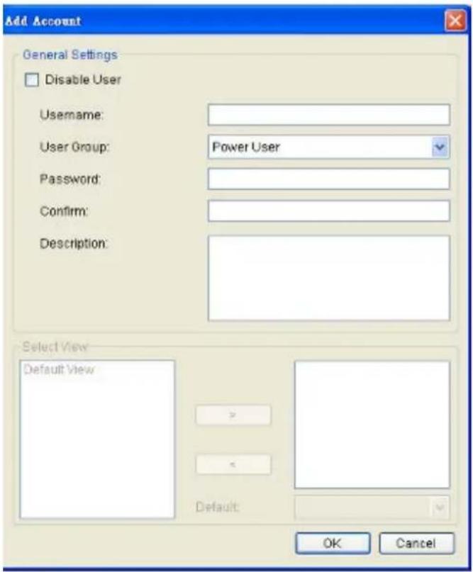
-
Click the Add button at the bottom of the Account List screen.
-
In the resulting screen fill out information for the new account:
Username
- User Group – Select a user type for this user. There are four options:
Administrator - This group has complete management privileges, including account and VMS/Server management rights.
Power User - This group has complete account management rights, but does not have many VMS/Server configuration rights. User - This group has no configuration rights and limited VMS/Server performance statistics.
Viewer - This group is limited only to viewing, and has no access to configuration or performance statistics.
-
Password / Confirm Password - The password must be typed twice for confirmation purposes.
■ Description – A simple description of the new user. -
If desired check the Disable User box to disable this account.
- Click Ok to add the new account. The account will appear in the Account List.
Editing an Account
To edit an account to the domain:
- Access the Account List node in the VMS Console.
- Select the account that you wish to edit by clicking on the account.
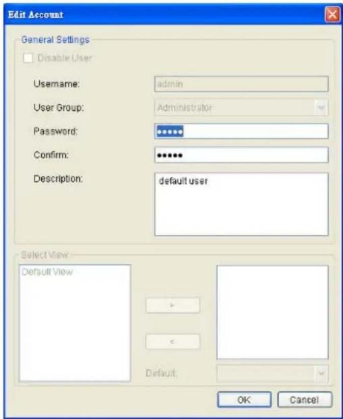
- Click the Edit button at the bottom of the Account List screen.
- In the resulting screen change any of the following account information:
■ User Group – Selects a user type for this user. There are four options:
Administrator - This group has complete management privileges, including account and VMS/ NVR Server management rights.
Power User - This group has complete account management rights, but does not have many VMS/NVR Server configuration rights.
User - This group has no configuration rights and limited VMS/ Server performance statistics.
Viewer - This group is limited only to viewing, and has no access to configuration or performance statistics.
-
Password/Confirm Password – If changed the password must be typed twice for confirmation purposes.
■ Description – A simple description of the user. -
If desired check the Disable User box to disable this account.
-
Click Ok to save the changes to the account. If the account description, user group or status changes, it will be reflected in the Account List.
Changing an Account Password
In addition to editing the password from using the Account List editing function, the password for the current account can also be changed by clicking the Change Password at the lower left corner of Account List Window.
This will display a dialog that allows you to enter and confirm a new password.
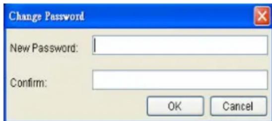
Deleting an Account
To delete an account to the domain:
- Access the Account List node in the VMS Console.
- Select the account that you wish to delete by clicking on the account.
- Click the Delete button at the bottom of the Account List screen.
- When prompted to confirm deletion click Yes to delete the account. The deletion will be reflected in the Account List.
Note: The Admin account cannot be deleted.
13.5.2. Functional Authority
Functionalities can be authorized according to different user levels.
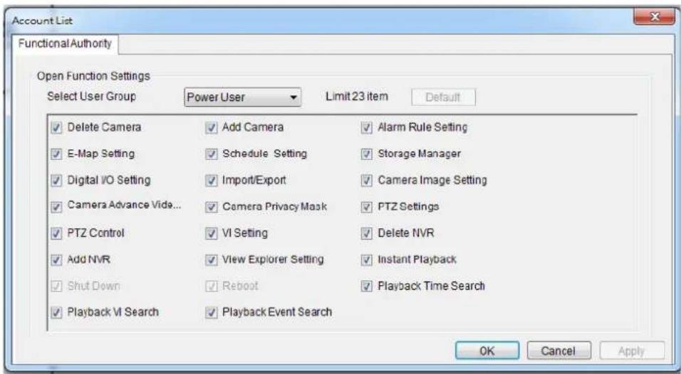
13.6. Network Parameters
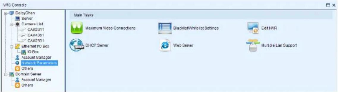
13.6.1. Main Tasks
Here you can access shortcuts for network parameter settings.
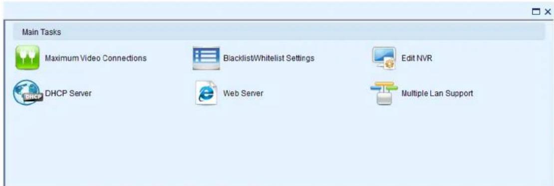
Maximum Video Connections
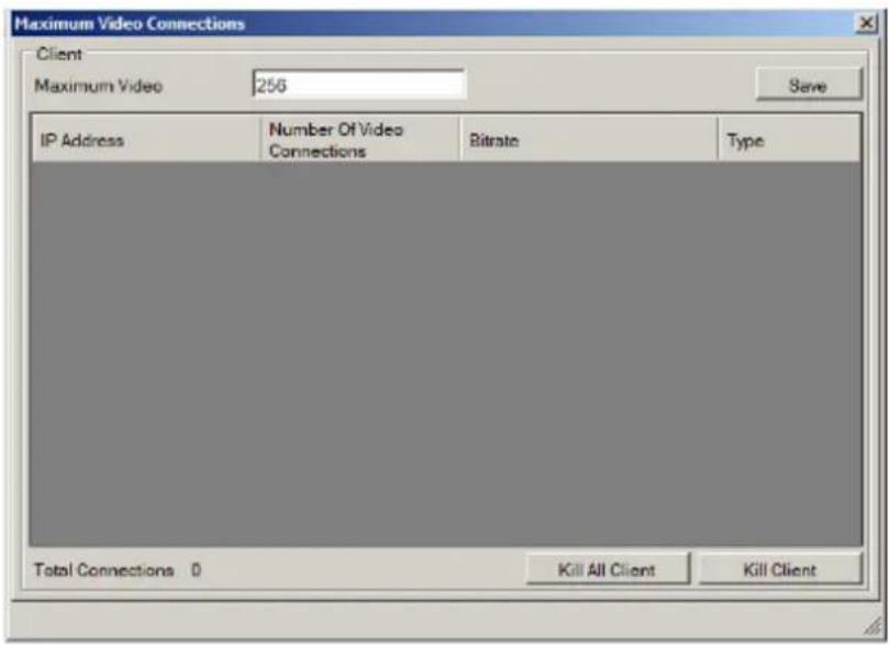
When clients are connected the following information will be displayed for each client:
IP Address
■ Number of Video Connections - The number of streams that the client is using.
- Bitrate - The total bitrate of that the client is consuming.
Type
There are also some options that can be changed in this dialog:
■ Maximum Connections - Change this number to limit the total number of video connections. Default is 256. Click Save to save the changes.
- Kill All Client - This button disconnects all clients connected on the Server.
- Kill Client – Selecting a client from the client list and clicking this button will disconnect the client from the Server.
Blacklist/Whitelist Settings
To setup a blacklist or whitelist:
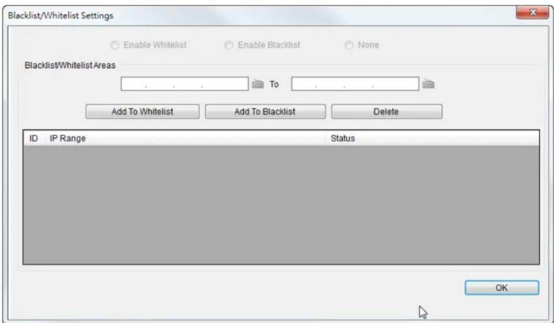
-
Enter an IP range in the two IP fields. The first IP address should be lower than the second IP address.
-
Click either Add to Whitelist or Add to Blacklist to add the IP range to the whitelist or blacklist respectively.
- Repeat the first two steps to set up the blacklist and whitelist. You can select ranges that have already been configured from the list and click Delete to delete them.
- When completed, click either Enable Whitelist to allow only the IP ranges on the whitelist to access the Server, or Enable Blacklist to block all the IP ranges on the blacklist from accessing the Server.
- Click OK to save your changes.
Edit NVR
Users can change both the setting of the stream port and the IP address by editing the Server.
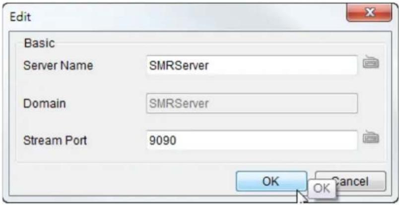
Web Server
For users who want to use the Web Client/SPhone Client, please fill in the following information for the Web Server settings.
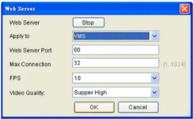
Note: (1) User may just keep the default settings in the Web Server. (2) Do not set the Web Server Port as these port numbers – 8080 (Web Stream Port), 9090 (NVR Stream Port), 2809 (NVR Server Login Port), 7735 (TV Wall Port (2.5.0)), 7734, 1024, 9010 (Domain Broadcast Port), 9030 (Domain Client Message Port), 9040 (Domain Console Message Port), 9050 (Domain Local Communication Port), 9020 (Domain Remote Communication Port), 9080 (Domain Local Log Data Download Port), 9081 (Domain Remote Log Data Download Port), 9060 (Domain Local Data Port), 9061 (Domain Remote Data Port), 15507 (Domain Local Log Message Download Port), 15503 (Domain Remote Log Message Download Port), 15501 (Domain Remote Log Upload port), 15505 (Domain Local Log Upload Port), 40000 (NVR Broadcast Port), 50000 (NVR Message Port).
Multiple LAN Support
Multiple network cards can be supported. Their information is listed as below:
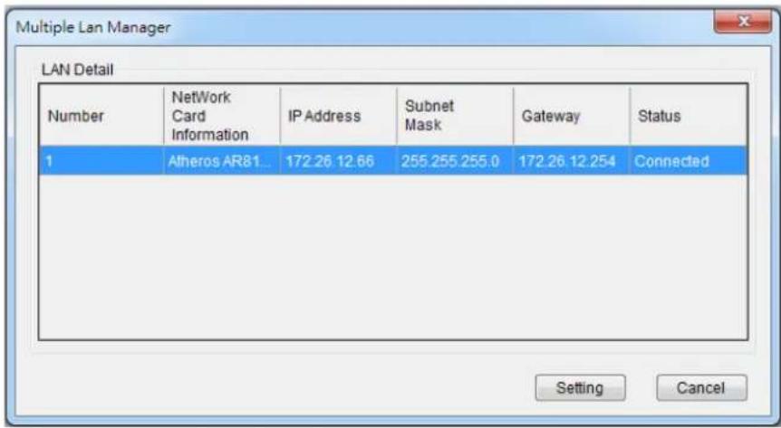
Click the "Setting" to set the Network Card to DHCP Auto-Configuration or Fixed IP Address.
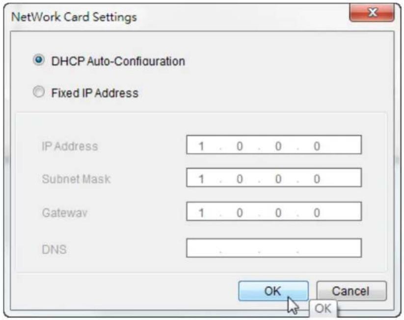
DHCP Server
The VMS has built in DHCP server functionality. Although this function is disabled by factory default, it should be turned on in the event that there is no DHCP service available. When enabled, the VMS will assume DHCP Server duties and assign addresses within the range specified.
Note: You may skip this step if you have separate DHCP service. Most routing devices will have DHCP capabilities.
- Right-click the VMS Server and select Configurations > DHCP Server option to bring up the DHCP Server dialog box.
- Fill in the following information:
IP Address Range - The range of addresses to be assigned. The first IP address should be lower than the second IP address.
Subnet Mask
Router - The router IP
Domain Name - The DNS IP
Note: DHCP service can also be configured by clicking Network Parameters > Main Tasks > DHCP Server in the VMS Console.
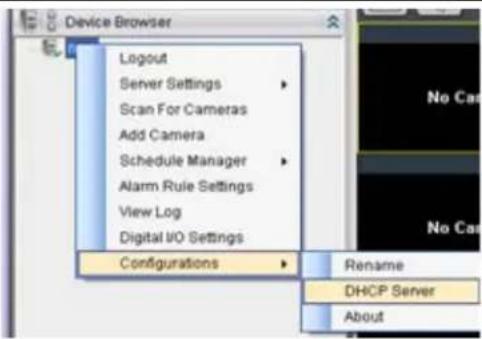
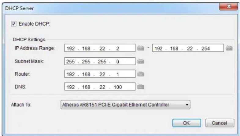
Note: The DHCP service should be attached to a network card.
13.7. Other Parameters
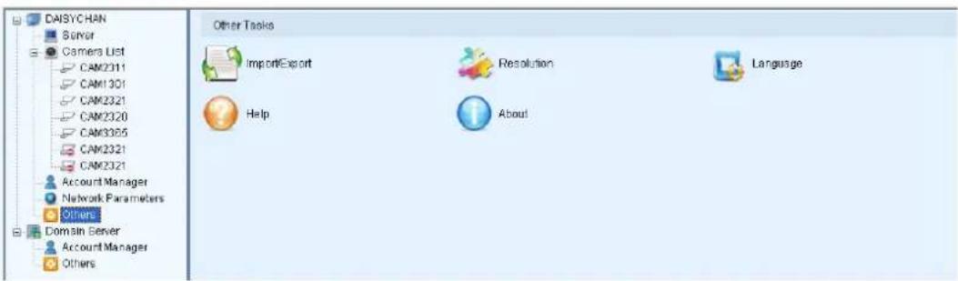
13.7.1. Other Tasks
Here you can access shortcuts for miscellaneous settings.
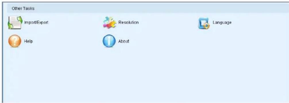
Import/Export
The following types of configuration/setup files can be imported/exported to the Server:
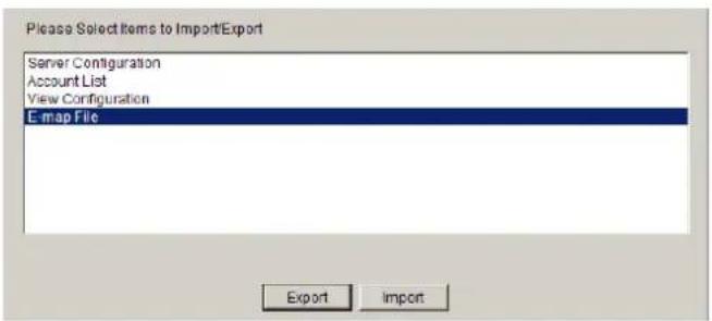
■ Server Configuration
Account List
View Configuration
E-map File
Importing Parameters
To import parameters into the Server:
- Select the item that you wish to import by clicking on the item type.
- Click the Import button. A windows explorer dialog will appear.
- Select the file to import from the file explorer, and click Open to import the file.
- Click OK to confirm import. The Server will require a restart before imported configurations and files are applied.
Exporting Parameters
To export parameters into the Server:
- Select the item that you wish to export by clicking on the item type.
- Click the Export button. A windows explorer dialog will appear.
- Input a filename and select the export path in the file explorer, and click Save to export the file.
Resolution
Shows the monitor resolution, and allows you to change its setting.
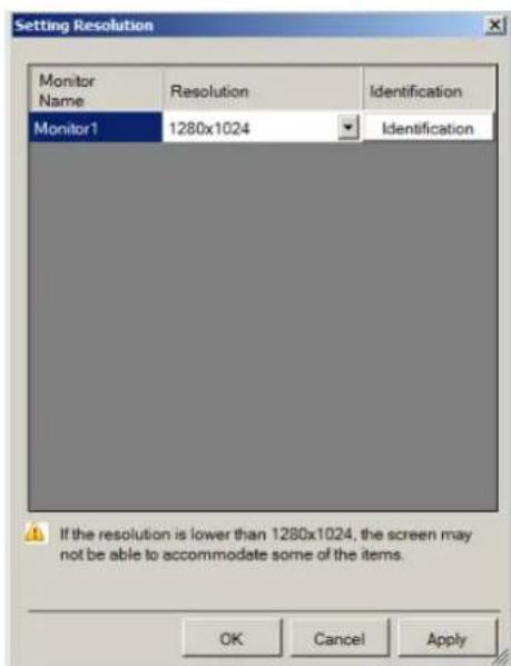
Language
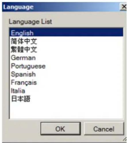
Allows you to change the interface language.
Help
Allows you to access the VMS User Manual.
About
Allows you to view server and client information. See Server Basic Functions > Viewing Server and Client Information for more details.
Chapter 14. System Maintenance
Warning: (1) Do not remove a failed component from the system until you have a replacement on hand. If you remove a failed component without replacing it, the internal airflow will be disrupted. (2) Qualified engineers who are familiar with the system should be the only ones who make component replacements.(3) When inserting a removable module, do not use excessive force. Forcing or slamming a module can damage the connector pins either on the module itself or on the backplane.
14.1. Replacing the Power Supply Module (for Rackmount Series)
Power supplies are redundant and load-sharing. PSUs are hot swappable!
Disconnect the power cord from the failed power supply. (Its LED should light static Red).
Place your thumb around the left side of the PSU ejection lever (circled in red) while hooking your index and middle finger around the PSU handles (circled in blue).
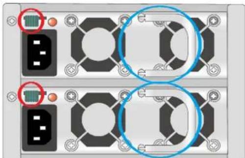
natural_image
Close-up of a mechanical or electronic component with two circular blue-circled features, no visible text or symbols.Use your thumb to push the lever in the direction of arrow (shown below) to disengage the power supply and use your index and middle finger hooked around the ejection lever to pull out the PSU.
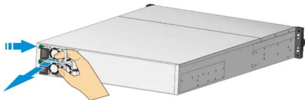
natural_image
Illustration of a server rack with a hand inserting a drive into the front panel (no text or symbols visible)To install the replacement module, make sure it is gently inserted and is pushed all the way in.
Connect the power cord, power on, and check if the LED lights static Green.
14.2. Replacing a Hard drive (for Desktop Series)
The easiest way to find out if your hard disk drive has failed is by looking at the hard drive status LED. If the power status lights up red, it indicates that that particular hard disk drive has failed. Hard drives are hot swappable, to replace it, please refer to the following procedure:
- Locate the failed hard drive with a red status LED (hard drive status LED).
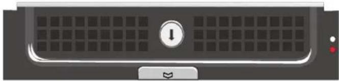
natural_image
Front view of a computer monitor with a grid and control buttons (no readable text or symbols)- Unlock the hard drive tray by turning the bezel to the unlock position.
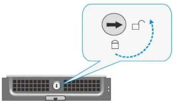
flowchart
graph TD
    A["Computer keyboard"] --> B{Interaction}
    B --> C["Arrow pointing to a circle with right arrow"]
    B --> D["Arrow pointing to a square with curved arrow"]
    B --> E["Arrow pointing to a lock icon"]
- Open the tray bezel by pushing the release button (indicated by the blue arrow) and the front bezel will automatically open.
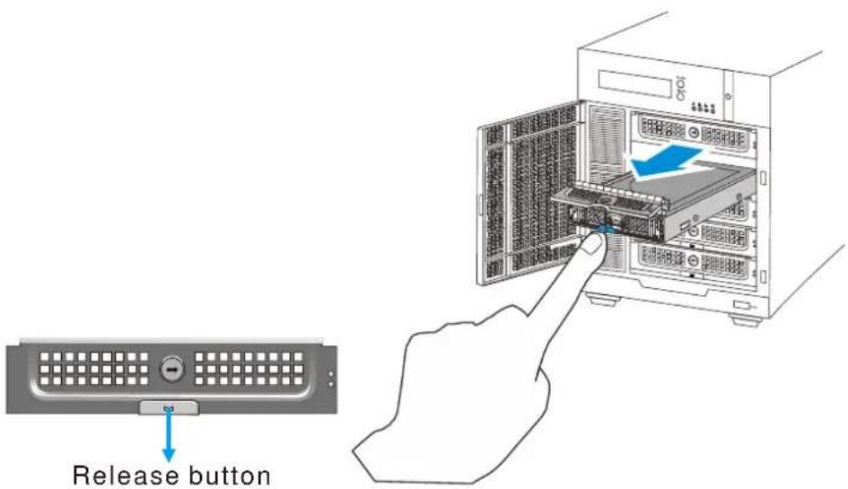
-
Remove the drive tray by pulling it one inch away from the drive bay. Wait for at least 30 seconds for the hard drive to spin-down, and then gently and carefully remove the drive tray from the chassis.
-
Remove the four retention screws that secure the hard drive from the sides of the drive tray (two on each side).
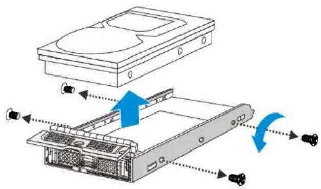
- Install the replacement hard drive as shown below and reinserted into the enclosure.
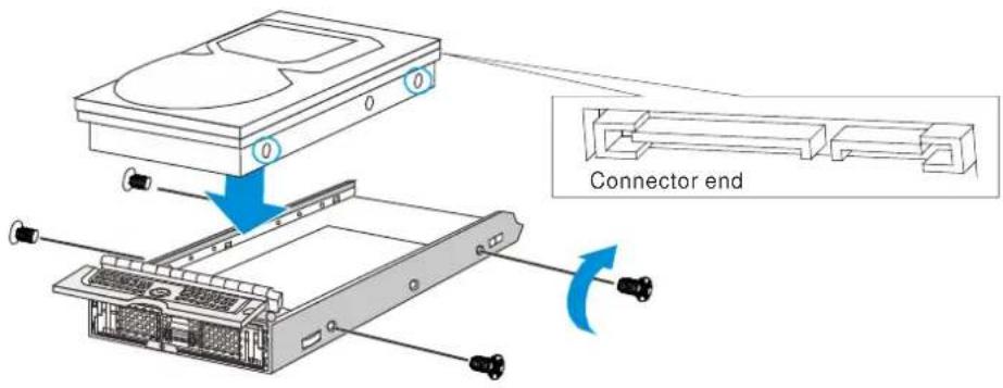
14.3. Replacing a Hard drive (for Rackmount Series)
The easiest way to find out if your hard disk drive has failed is by looking at its status LED. If the power status lights up red, it indicates that the particular hard disk drive has failed.
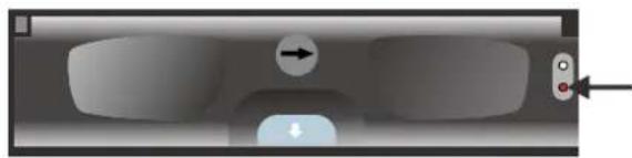
natural_image
Interior view of a vehicle dashboard with a directional arrow and control knob (no text or symbols)Hard disk drives are hot swappable and to replace the failed hard drive, use a small flathead screwdriver to rotate the bezel lock from the lock position to the unlock position.
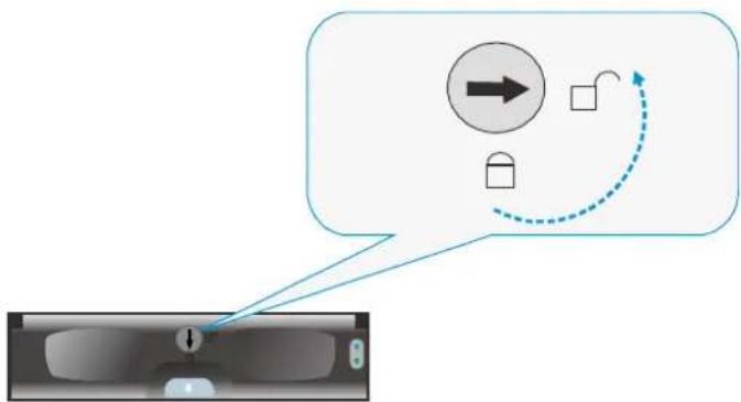
flowchart
graph TD
    A["Input"] --> B{Process}
    B -->|Yes| C["Output"]
    B -->|No| D["Feedback Loop"]
    D --> E["Arrow to Process"]
    style A fill:#f9f,stroke:#333
    style E fill:#bbf,stroke:#333
Press the release button on the tray bezel to open the bezel.
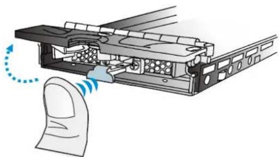
natural_image
Diagram of a computer mouse with a finger pointing to the internal structure (no text or symbols present)Remove the drive tray by pulling it one inch out of the drive bay and wait for at least 30 seconds for the disk drive to spin-down and then gently pull out the drive tray from the chassis.
Remove the four retention screws that secure the hard drive from the sides of the drive tray (two on each side).
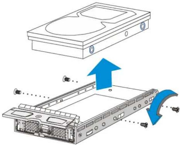
natural_image
Diagram showing a computer drive assembly with an open rear case and a blue directional arrow indicating motion (no text or symbols present)14.4. Restore Default Settings
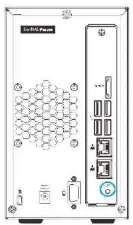
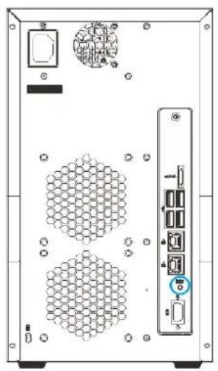
natural_image
Back view of a server rack unit with hexagonal grid patterns and labeled ports (no readable text or symbols)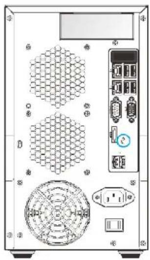
natural_image
Back view of a computer tower case with hexagonal and circular components (no visible text or labels)Use the tip of a pen to press and hold the restore button for 3\~5 seconds and release, a beep will sound to indicate that default settings have been restored:
| Restores the following settings | Retains the following settings |
| 1. NVR General Settings2. VMS Console Settings3. General Server Settings4. Notification Settings5. Pre/ Post Alarm Settings6. Schedule Manager Settings7. Alarm Rule Settings8. Digital I/O Settings9. SMR/ VMS Configurations (ex: DHCP Server...)10. Camera Settings11. Image/ Video Settings12. VI Settings13. PTZ Settings | 1. Log information2. Video recordings3. HDD RAID configuration4. Storage Manager Settings |
Chapter 15. AC Device Tool
AC Device Tool is a small but useful tool for you to have easy access control. AC Device Tool connects Access Control System and NVR, via NVR connecting to IP camera to provide live video and event associated playback. It's now compatible with the Suprema Access Control System.
15.1. Installing the Access Control Device Tool
- Click on the installer icon and begin the AC Device Tool installation.
- You need to make sure that you have administrator privilege on your system before the installation begins.
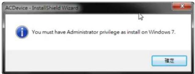
- After confirmation, an InstallShield Wizard for AC Device will guide you through all the installation steps. Click "Next" to continue.
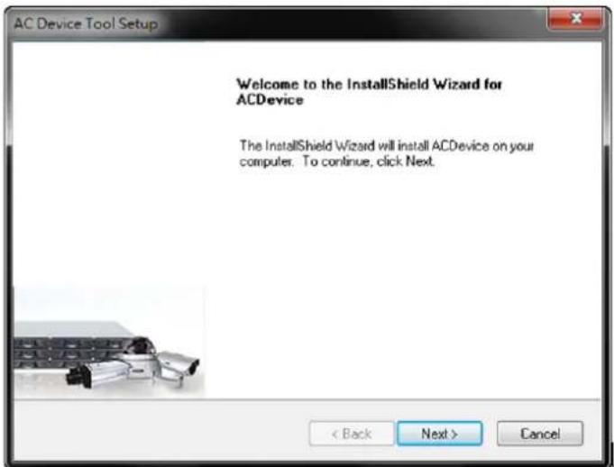
- Select "Typical" to have all in one single AC Device Tool application. Select "Advanced" to have an individual AC Device Tool installation. After selected, click "Next" to continue.
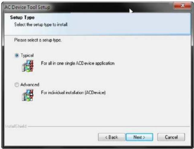
- Click "Browser" to choose a destination location for the install files. After selected, click "Next" to continue.
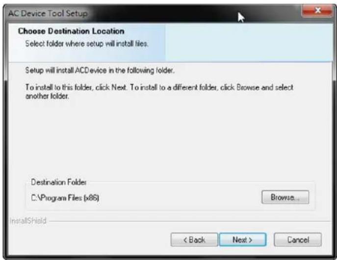
- Select the features you'd like to install. After selected, click "Next" to continue.
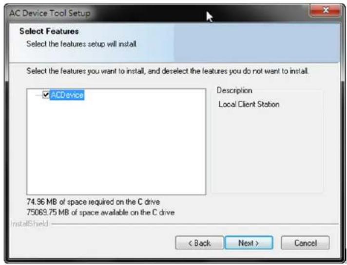
- Click "Install" to begin the installation.
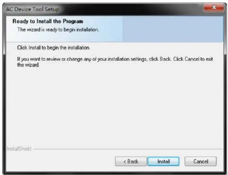
- A setup status bar will show up on the screen to indicate the progress.
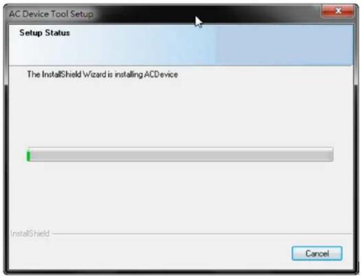
- After the AC Device Tool installation is complete, click "Finish" to exit.
- After that you'll see a new icon on your desktop. The AC Device Tool installation is now complete.
15.2. How AC Device Tool works
- Click on the AC Device Tool icon to open and add Device Mapping.
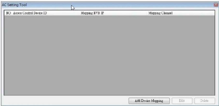
- Key in the information required to have your Access Control device mapped.
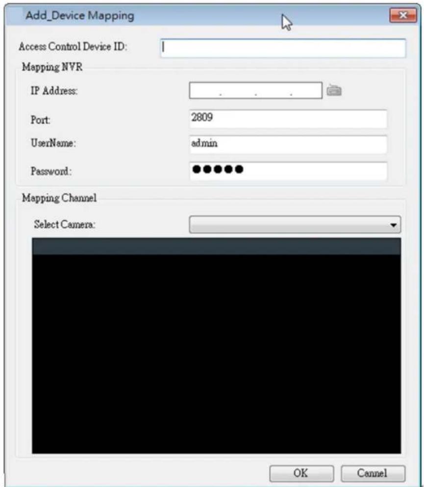
- After setup, when using the Suprema Access Control System, you can click on the camera icon on the Log List to have a 10-minutes playback images.
![Door/Zone Monitoring | Realtime Monitoring Log List Period 2011-07-01 Event Priority 0 Get Log Clear ~ 2011-07-01 User Network Log Show Image Device ID Date Device Device Event T&A Event User ID Status 2011-07-01 10:11:52 112 112[192....] Verify Success(Card Only) 9 2011-07-01 10:11:53 112 112[192....] Door Relay On 0 2011-07-01 10:11:57 112 112[192....] Verify Success(Card Only) 9 2011-07-01 10:11:58 112 112[192....] Door Relay On 0 2011-07-01 10:12:03 112 112[192....] Verify Success(Card Only) 9 2011-07-01 10:12:03 112 112[192....] Door Relay On 0](/content/2026/06/1178915/images/03dfc91deff29d5b24528e894b6728b937d16727caf891b9010a9a2a92043706.jpg)