CAM4365 - Security Camera Surveon - Free user manual and instructions
Find the device manual for free CAM4365 Surveon in PDF.

| Product Type | Security Camera |
| Brand | Surveon |
| Model | CAM4365 |
| Dimensions (W x H x D) | Approx. 70 x 180 x 70 mm |
| Weight | Approx. 0.5 kg |
| Power Supply | PoE (802.3af) or 12V DC |
| Power Consumption | Max. 7W |
| Image Sensor | 1/2.7" Progressive CMOS |
| Resolution | 5 Megapixels (2592 x 1944) |
| Frame Rate | 20fps at 5MP |
| Lens | 2.8mm fixed focal |
| Field of View | Horizontal: 90°, Vertical: 70° |
| IR Distance | Up to 30m |
| Video Compression | H.265, H.264, MJPEG |
| Day/Night Function | Yes, with ICR filter |
| Motion Detection | Yes |
| Weatherproof Rating | IP66 |
| Operating Temperature | -30°C to 60°C |
| Storage Temperature | -40°C to 70°C |
| Recommended Maintenance | Clean lens with dry soft cloth; avoid water jet |
| Safety Precautions | Disconnect power before cleaning; do not disassemble |
| Spare Parts Availability | Contact Surveon support |
| General Information | Bullet style network camera for outdoor use |
Frequently Asked Questions - CAM4365 Surveon
User questions about CAM4365 Surveon
0 question about this device. Answer the ones you know or ask your own.
Ask a new question about this device
Download the instructions for your Security Camera in PDF format for free! Find your manual CAM4365 - Surveon and take your electronic device back in hand. On this page are published all the documents necessary for the use of your device. CAM4365 by Surveon.
USER MANUAL CAM4365 Surveon
Outdoor Network Camera
User Manual
Release 1.2
All Rights Reserved © Surveon Technology 2011
Copyright Statement
No part of this publication may be reproduced, transmitted, transcribed, stored in a retrieval system, or translated into any language or computer language, in any form or by any means, electronic, mechanical, magnetic, optical, chemical, manual or otherwise, without the prior written consent of Surveon Technology Inc.
Disclaimer
Surveon Technology makes no representations or warranties with respect to the contents hereof and specifically disclaim any implied warranties of merchantability or fitness for any particular purpose. Furthermore, Surveon Technology reserves the right to revise this publication and to make changes from time to time in the content hereof without obligation to notify any person of such revisions or changes. Product specifications are also subject to change without notice.
Trademarks
Surveon and Surveon logo are trademarks of Surveon Technology Inc. All other names, brands, products or services are trademarks or registered trademarks of their respective owners
Table of Contents
Copyright Statement ...... 2
Chapter 1. Overview ......5
1.1. Network Camera Introduction ....5
1.2. Network Camera Features....5
1.3. Network Camera Specifications ....6
1.4. Network Camera Hardware Installation....8
Chapter 2. Connecting to the Network Camera....9
2.1. Connecting with a Web Browser 10
Connecting to the Network Camera with a web browser 10
Logging into the System for the First Time.... 10
Installing Active X Components in Internet Explorer.... 11
Logging Out of the System 12
Using the Help Interface 12
2.2. Connecting with an RTSP Player .... 13
Connecting with a Mobile Device RTSP Player 13
Chapter 3. Web Interface ...... 14
3.1. Interface Layout.... 14
Control Descriptions 15
3.2. Settings.... 17
General 17
Basic Settings 17
User Account.... 19
Date & Time.... 22
Network 24
Network Configuration 24
Port Settings 25
UPnP 27
Video & Audio Settings 28
Basic Settings 28
Image Appearance 29
Video Streams 34
Audio Settings.... 36
Recording.... 37
Recording Basic Settings 37
Recorded File Management 38
Event Notification.... 40
Event Server 40
Motion Detection 42
DI & DO 44
Event Settings.... 46
System 52
MicroSD Card Management.... 52
System Status 53
System log....53
Firmware Upgrade 55
Export/Import & Reboot 57
Chapter 1. Overview
1.1. Network Camera Introduction
CAM4365 is a professional IP network camera that uses Internet Protocol (IP) to transmit video streams and control signals over networks. Capable of operating over both LANs and WANs, CAM4365 provides a complete budget-conscious remote surveillance solution that is ultra clear and highly integrated. CAM4365 combines a user-friendly interface and simplified installation with a powerful feature set, to provide users an easy upgrade path to new digital surveillance system in a virtual environment. These highlights make CAM4365 an ideal choice for environments that require remote surveillance or video transmission.
1.2. Network Camera Features
■ Supports up to 10 simultaneous users.
Built-in web server to allow real-time remote surveillance and control using standard web browsers.
■ Supports dynamic IP, LAN, and the Internet (ADSL, Cable modem).
■ Supports most network protocols including: HTTP, TCP/IP, DNS, DHCP, RTSP, PPPoE.
■ Automatically adapts image compression rate to available bandwidth
■ Supports image recording and still image capture.
■ Self-recovery feature automatically re-establishes broken network connections.
IP66 Weather and Dustproof Construction.
1.3. Network Camera Specifications
| CAM4365 | |
| Image sensor 1/2.8” 3 megapixel Sony low-light CMOS | |
| Lens 3 - 10 mm motorized lens, F1.3 | |
| Viewing Angle Diagonal:122°~35° | |
| Horizontal:96°~28° | |
| Vertical:72°~21° | |
| WDR Yes | |
| Day/Night Yes | |
| IR LED Yes (15m) | |
| Min illumination | 0 lux (IR LEDs on) |
| Iris control Yes | |
| Shutter time 1/5 ~ 1/15,000 s | |
| Camera Angle Adjustment | Pan: 0° ~ 340° |
| Tilt: 30° ~ 90° | |
| Video compression | H.264 / MPEG-4 / MJPEG |
| Resolution Up to 2048x1536 | |
| Video control Auto Gain Control, Auto White Balance, Backlight Compensation, Image Adjustment | |
| Frame rate 15 fps at QXGA (2048 x 1536) | |
| 30 fps at 1080P (1920 x 1080) | |
| 30 fps at SXGA (1280 x 1024) | |
| 30 fps at HD720 (1280 x 720) | |
| 30 fps at VGA (640 x 480) | |
| 30 fps at QVGA (320 x 240) | |
| Video stream | 2 simultaneous streams at H.264, MPEG-4, and MJPEG |
| Bit rate | 32K ~ 10Mbps, VBR, CBR, controller frame rate and quality |
| Intelligent video | Motion detection, tampering detection* (blocked, redirected, defocused, or spray-painted) |
| Audio compression | 32KHz, ADPCM, G.711 |
| Audio input | 3.5mm phone jack |
| Audio output | 3.5mm phone jack |
| Alarm in | 2, terminal block |
| Alarm out 1, terminal block | |
| AUX Power Output | 12VDC 400mA |
| Video buffer 5 second pre-alarm | |
| 30 second post-alarm | |
| Event action Send snapshot or video clip by FTP or email, record to NAS, record to local storage, trigger DO | |
| Supported protocols | IPv4, ARP, TCP, UDP, ICMP, DHCP, HTTP, UPnP, RTSP, RTCP, NTP*, DDNS, SMTP*, FTP*, CIFS*, PPPoE*, 3GPP*, RTP*, Multicast* |
| Ethernet 10/100 Base-T / RJ45 | |
| Local storage microSD/SDHC x 1 (Class 4/Class 6 only) | |
| RS-485 1 (2 pins on terminal block) | |
| SDK Surveon SDK 2.0 | |
| OS Microsoft Windows XP/Vista/7 | |
| Browser Microsoft IE 6.0 or above | |
| Software Surveon VMS 2.4.1 | |
| Temperature Operation: -25°C ~ 50°C (-4°F ~ 122°F)Non-operation: -30°C ~ 60°C (-22°F ~ 140°F) | |
| Humidity 5% ~ 95% | |
| Power 12VDC 1.5A; PoE (IEEE 802.3af) with Class 3 | |
| Power consumption Max. 7.5 W (w/o Heater, no AUX power)Max. 12 W (w/ Heater, no AUX power) | |
| Dimension ø 144 mm x 116 mm (H)ø 5.67" x 4.57"(H) | |
| Weight Net: 1,260g (2.78lb.)Gross: 1,930g (4.27lb.) | |
| Certification Safety: LVDEMC: FCC, CEIP66 | |
* Supported in future releases
1.4. Network Camera Hardware Installation
Before the network camera is configured:
- Install the camera in a suitable spot. The camera should have an unobstructed view of the area to be surveyed.
- Connect the camera to a power source. CAM4365 can accept power from a power adapter or from Power over Ethernet enabled switches.
- Connect the camera to a switch using an Ethernet cable. The Ethernet port is located on the rear of the camera.
Chapter 2. Connecting to the Network Camera
This section demonstrates how to connect to the network camera through two methods:
- Web Browser - A simple web-based interface. Internet Explorer is the recommended web browser for use with Surveon network cameras, and our examples will be from this browser. Usage on other browsers will be similar.
- RTSP Player - These include common streaming media players, such as RealPlayer or Quicktime Player. These players can provide live view of the camera using the Real-Time Streaming Protocol (RTSP).
2.1. Connecting with a Web Browser
Connecting to the Network Camera with a web browser
- Launch the web browser (Microsoft ® Internet Explorer 6.0 or higher is recommended).
- Enter the IP address of the network camera in the address bar of your browser and press enter. The IP address can be obtained using the Surveon IP Utility, or if your network does not have DHCP service, the default IP address is 192.168.88.10.
Logging into the System for the First Time
If this is the first time that the network camera is being accessed, the camera will prompt you to change the administrator password after your first login.
Click OK.
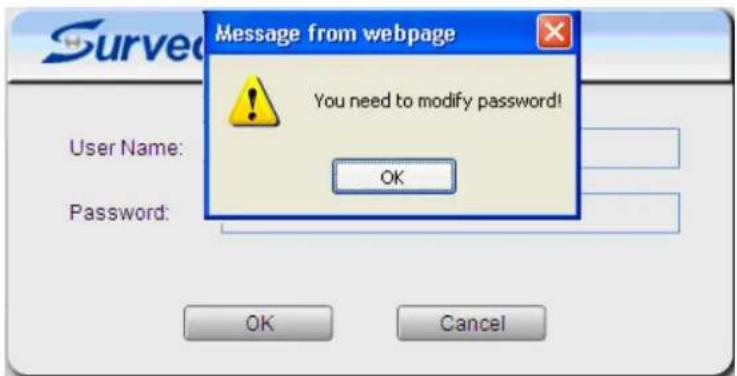
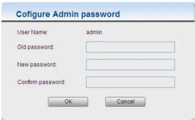
- Click OK when informed of the need to change your password. This will cause a Configure Admin Password popup to display.
- In the Old password field, fill in the old password (default is admin).
- In the New password and Confirm new password field, fill in the new password.
- Click OK to change the password. If at any time you lose this password, performing a hard reset of the camera will restore the password back to admin.
Installing Active X Components in Internet Explorer
You may be prompted to install ActiveX® components when accessing the network camera's Live View page; click Yes when prompted. You will be able to access the camera after installation is completed. Under Windows, this action may require administrator privileges.
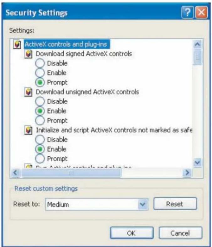
If the dialog box suggests that you are not allowed to install ActiveX components, try resolving the problem using the following steps:
- In Internet Explorer, open Tools> Internet Options> Security. Click the Custom level button.
- Search for Download signed ActiveX controls. Under this heading select Prompt and then click OK.
-
Continue installing the Active X components.
-
After installing ActiveX, go to Tools> Internet Options> Trusted Websites> Sites and add the IP Address of the camera.
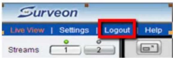
Logging Out of the System
Logging off of the camera can be performed by closing the browser window.
Users can also choose to click the Logout link located at the top of the screen.
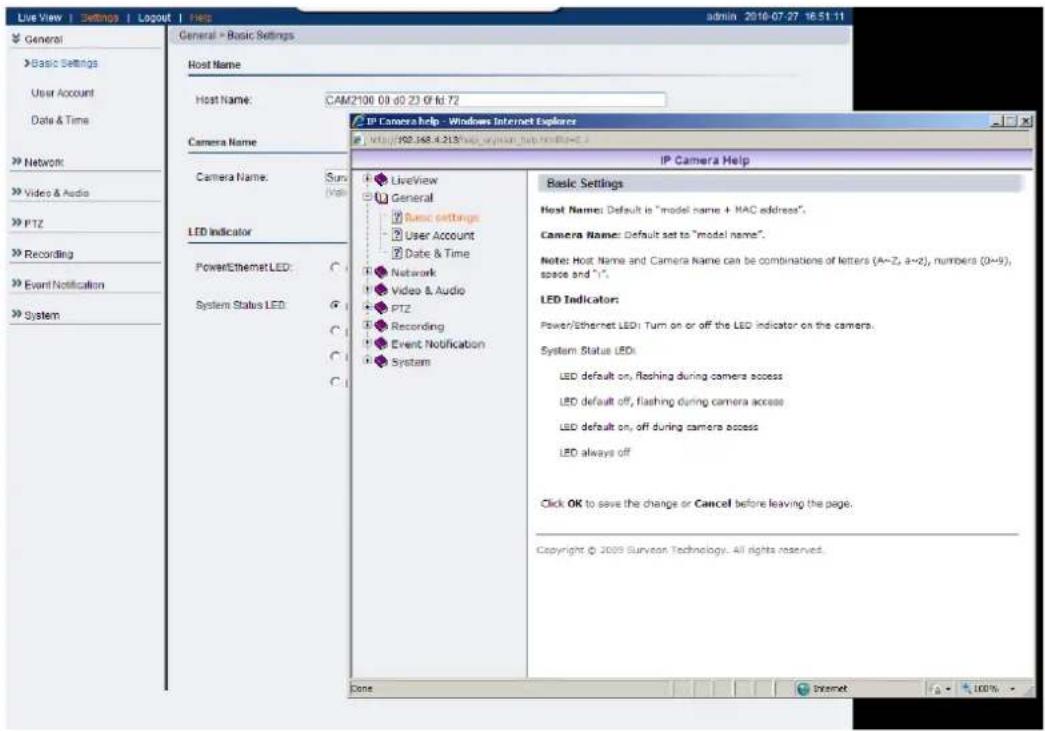
Using the Help Interface
While using the web interface, you may click on the Help link located under the title bar. This will bring up a pop-up containing the IP Camera Help manual. This provides simple explanation of the camera settings, and will automatically open to the page relevant to your current screen.
The help manual is organized so that it matches the system menus, with sections corresponding to each settings menu and the Live-view window.
2.2. Connecting with an RTSP Player
Surveon cameras support connections through RTSP Media Players such as Real Player and QuickTime Player. We will use Real Player as an example in this section.
- Launch Real Player or QuickTime Player :
- Select File> Open URL, to open a URL dialog box.
- Enter the camera URL in the address bar.
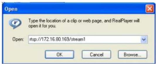
Note: The format for RTSP is: rtsp://
- Click OK, the stream should begin playing.
Connecting with a Mobile Device RTSP Player
In order to access streaming video on 3GPP mobile devices, please make sure the network camera is already online and connected to the Internet. In the IP field under the IP Address section of the window, enter the IP address of the IP camera.
- Change the settings under Settings> Video & Audio> Stream2 Setting to 3GPP Mode
- Launch the RTSP Player on the 3GPP mobile device and enter the URL address for the camera. The video should start playing.
Note: The format for RTSP is: rtsp://
Chapter 3. Web Interface
3.1. Interface Layout
This section demonstrates the layout of the network camera's main interface.
The 4 main areas on the interface are:
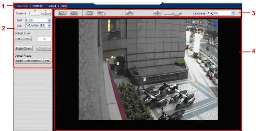
-
Menu Bar - The links on this bar allow users to toggle between live-view and settings screens, as well as logout and pull up the help menu.
-
Live View Controls - These controls allow users to configure the live view streams and camera live view functionality.
-
Button Bar - These controls allow the user to quickly access common features such as live view window resizing, video and still frame capture, interface language, and audio controls.
-
Live View Window - This portion of the screen displays the stream selected in the Live View Control section of the web interface.
Control Descriptions
| Control Description | |
Adjust Window Size: | When clicked, the display window size can be adjusted manually to fit the screen. The screen size changes back to the actual image size (resolution). |
 | Full-Screen: Goes to full-screen when clicked; press “ESC” to return to windowed view. |
Image Capture: | When clicked, captures the current screen as an image in a new pop-up window and saves it in C:\Surveon\Record. This location can be changed under Settings>Recording>Recording Basic Settings.The file name is set to “Camera Name”+yyyymmdd_hhmmss (the Camera Name can be changed under Settings>General>Basic Settings). |
 | Manual Record: When clicked, records the current live video. Stops recording when clicked again. The default location for storing the recording is C:\Surveon\Record.This location can be changed under Settings>Recording>Recording Basic Settings. |
Audio-In: | By default; clicking once allows audio to be transmitted from a local microphone to the camera. Clicking again stops audio transmission. Multiple users may access the live view page and receive audio from the camera, but only one user at once is allowed to send audio to the camera. |
| Mute:Mutes the audio | Audio captured by the camera when clicked, un-mutes the audio when clicked again. |
 | Volume: Sets to the current computer volume; Dragging the slider adjusts the volume. |
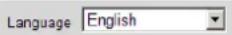 | Language: Sets the UI language. Available languages include English, Simplified Chinese, and Traditional Chinese. |
| Control Description | |
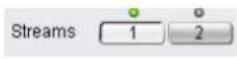 | Streams: Allows users to choose which camera stream to view. The indicator above the stream will turn light green when the stream is selected. |
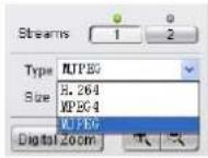 | Video Format: Sets the compression format for the current stream. Available formats are H.264, MPEG4, and MJPEG. |
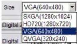 | Image size (resolution): Sets the resolution of the stream currently selected. Options are available for each stream: 1536P (2048 x 1536), 1080P (1920 x 1080), SXGA (1280 x 1024), 720P (1280 x 720), VGA (640 x 480), QVGA (320 x 240) for stream 1 and VGA (640 x 480), QVGA (320 x 240), QQVGA (160 x 120) for stream 2. |
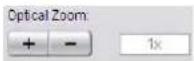 | Optical Zoom: Clicking the + button zooms in and clicking the - button zooms out. The total magnification is displayed in the box beside the buttons. |
Digital Zoom: When  | clicked, activates digital zoom in the current live-view stream. 2 options are available when clicked: Zoom InZoom Out Zoom InZoom Out |
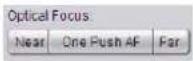 | Optical Focus: Clicking the Near button will move the focus point nearer, while clicking on the Far button will move the focus point farther. Clicking on One Push AF will automatically dial in the correct focus for the center point. |
3.2. Settings
Camera settings may be changed by clicking on the Settings link located in the title bar. This will bring up a menu list of configuration menus for all major camera settings.
General
General setting menus are found under Settings> General.
Basic Settings
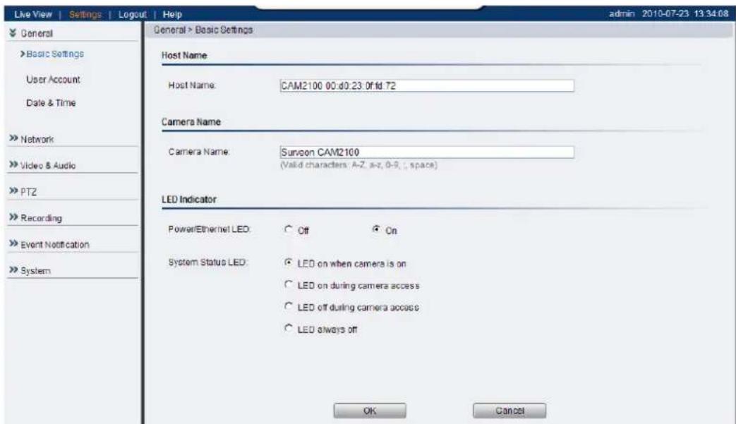
Basic settings may be accessed under General> Basic Settings. The following settings can be made:
- Host Name: by default set to "model name + MAC address"; displays on the center of the main page. Users may replace the default name with a new name consisting of alphanumeric characters, spaces and the ":" character.
- Camera Name: by default set to "Surveon + model name"; after selecting Camera Name" from Settings> Video & Audio> Basic Settings, the Camera Name will show on the display. Users may replace the default name with a new name consisting of alphanumeric characters, spaces and the ":" character.
- Power/Ethernet LED: turns on or off the power and Ethernet LEDs indicator on the rear of the camera.
- System Status LED: changes the behavior of the status LED on the front
of the camera. There are four possible behaviors:
- LED on when camera is on - LED default on, flashing during camera access.
- LED on during camera access - LED default off, flashing during camera access
- LED off during camera access - LED default on, off during camera access
- LED always off - LED always off
Click OK to save or Cancel to abort the changes before you leave the page.
User Account
The User Account section, found under General> User Account, controls the user account information and privileges.
![Live View | Settings | Logout | Help General > User Account User Account User Name User Group admin Administrator guest Operator Madnum number of administrators/operators is 10 Add Edit Remove User Login Settings Enable access without login Madnum number of simultaneous viewers limited to 10 [1..10] OK Cancel](/content/2026/05/1060361/images/a937b6e99d809121dcdc23f90dde81ac80e21d3b9e5e578ec61868d2ed591f2b.jpg)
There are two pre-configured accounts:
- admin - This is the default administration account, and cannot be deleted.
- guest - This is an account with only live view capability.
There are also two basic settings under user account settings:
- Enable access without login - Checking the checkbox will allow users to view the camera stream without having to login.
- Maximum number of simultaneous viewers limited to - Enter a number from 1 to 10 in this field to limit the number of users that can view the live view stream for this camera. This option will only be displayed once you add an account.
Click OK to save or Cancel to abort the changes before you leave the page.
Adding Accounts
In General> User Account under the User Account heading, click on "Add". Up to 10 accounts can be added to the system.
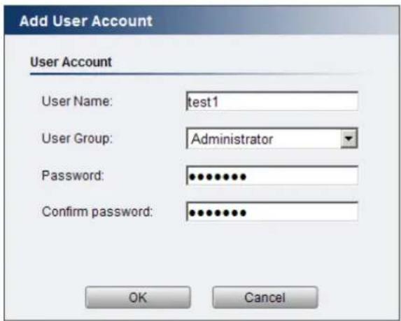
All User Names and Passwords must be combinations of alphanumeric characters, “:”, “-“, “_” between 4 and 20 characters in length, and must begin with an alphabet letter. Fill out the following fields:
- User Name - The identifier name used to login to the system.
- User Group - The system allows for 2 types of users.
○ Administrator - Administrators have full access privileges.
- Operator - Operators can only access the live view page.
- Password - A passkey used to control user access. The password must be a combination of alphanumeric characters, “:”, “-”, “_” between 4 and 20 characters in length, and must begin with an alphabet letter.
This password should be retyped in the Confirm password field, to ensure that the correct key is saved.
Click OK when finished to add the user to the system.
Editing Accounts
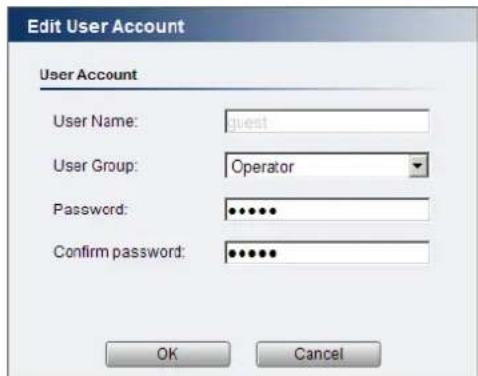
In General> User Account under the User Account heading, select an existing account by clicking on the account entry. The entry will be highlighted in yellow. Clicking Edit will allow you to change the following fields:
- User Group - The system allows for 2 types of users.
○ Administrator - Administrators have full access privileges.
- Operator - Operators can only access the live view page.
- Password - A passkey used to control user access. The password must be a combination of alphanumeric characters, “:”, “-”, “_” between 4 and 20 characters in length, and must begin with an alphabet letter. This password should be retyped in the Confirm password field, to ensure that the correct key is saved.
Click OK when finished to save any changes.
Note: Only accounts that are not currently logged-in can be edited.
Deleting Accounts
In General> User Account under the User Account heading, select an existing account by clicking on the account entry. The entry will be highlighted in yellow. Click Remove and, when prompted to confirm deletion, click OK to remove the account.
Date & Time
Date and time settings can be accessed at General> Date & Time.
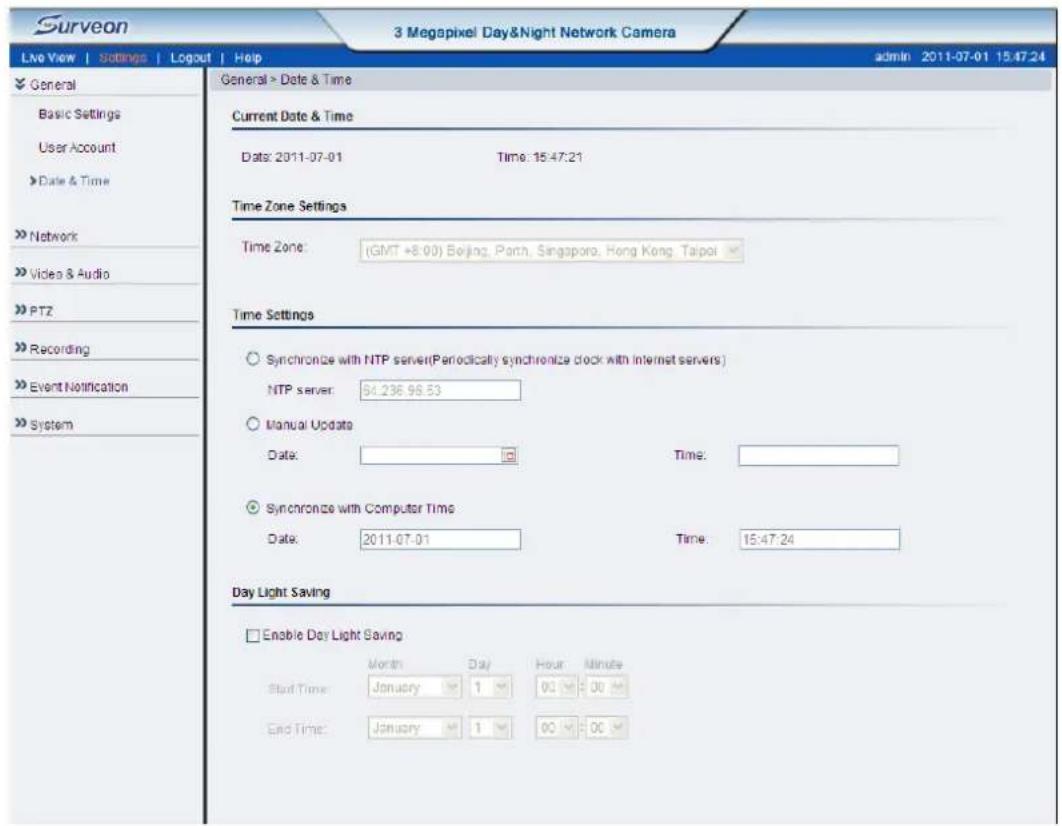
Current Date & Time displays the current system date and time.
Time Zone Settings
The time zone can be set using the dropdown menu. This menu is only applicable when selectable when Synchronize with NTP Server is chosen under Time Settings.
Time Settings
There are 3 ways to set the system time:
- Synchronize with NTP server - NTP is a protocol for synchronizing the system clock to an external server. If this option is chosen, enter the IP address of a known NTP server in the NTP Server field. You must also choose the appropriate time zone under Time Zone Settings.
- Manual update - Updates the time manually. Choose the appropriate date and enter a time for the system.
- Synchronize with computer time - Synchronizes the time with the computer's internal clock.
Day Night Saving
Users can set the Day Light Saving Time by ticking on Enable Daylight Saving.
Click OK to save or Cancel to abort the changes before you leave the page.
Network
The network settings, including network configuration, port configuration, and universal plug and play (UPnP) settings are used to configure camera connectivity. These settings are found under the Settings > Network context.
Network Configuration
These settings are used to configure basic network access for the camera. They are found under Network> Network Configuration.
Most of these settings vary with your specific hardware setup; therefore the defaults are set for common SOHO level usage. If you are using the camera in an enterprise environment, please check with your IT department to determine the correct settings for this section.
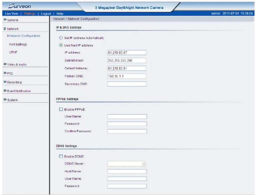
IP & DNS Settings
These settings are used to determine the IP address of the network camera.
- Get IP address automatically - Automatically acquires IP address from a DHCP service. This is the default setting
- Use fixed IP address - Sets a fixed IP address. You must also manually fill in IP address, Subnet mask, Default gateway, Primary DNS, and
Secondary DNS fields. The network camera can be connected to the network upon completion.
PPPoE Settings
This feature is disabled by default. Connecting to the network using PPPoE (Point-to-Point Protocol over Ethernet) requires a user name and password from your ISP (Internet Service Provider). Select Enable PPPoE and fill in valid user name and password to connect the camera to the Internet.
DDNS Settings
DDNS (Dynamic Domain Name Server) is a protocol that enables the camera to maintain a static connection address, even when its IP changes. Access using this feature is disabled by default.
Connecting using DDNS requires registration on third-party websites for DDNS services. Select desired DDNS service website, check the Enable DDNS option, and fill in valid user name and password. You can then access the camera through the registered domain name.
Click OK to save or Cancel to abort the changes before you leave the page.
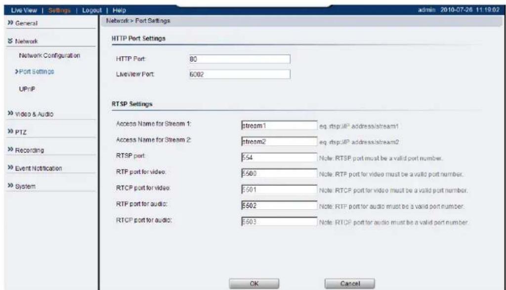
Port Settings
Ports are a software construct used to multiplex the transmission information to and from the camera. They act as separate endpoints within an IP address where software "listens" for incoming information. This section, which can be accessed under Network> Port Settings, includes HTTP Port Settings and RTSP Settings.
The default port numbers in this section are, for the most part, well-known or
commonly known values. We recommend that they not be changed unless there is a specific reason to do so.
HTTP Port Settings
The HTTP port number is used access the camera via the HTTP protocol.
TheLiveViewPortnumberisusedtotransmitlive-viewinformation.
RTSP Settings
Real-Time Streaming Protocol (RTSP) is a protocol used to establish and control media sessions between end points.
You may change the access name for stream 1, stream 2, the RTSP port number, the RTP port for video, the RTP port for audio, the RTCP port for video, and the RTCP port for audio.
Note: The RTP port number must be an even number. After entering the RTP port number, the RTCP port number will automatically be set to the RTP port number + 1.
Click OK to save or Cancel to abort the changes before you leave the page.
UPnP
![Live View | Settings | Logout | Help Network > UPnP UPnP Settings Enable UPnP Friendly Name: Surveon CAM2100 Interval: 100 [10 Sec - 300 Sec] OK Cancel General Network Network Configuration Port Settings UPnP Video & Audio PTZ Recording Event Notification System](/content/2026/05/1060361/images/db0479c6df15be400f093707e44d3fc96b51c5b5ac681f05f7444dab19035b02.jpg)
Universal plug and play (UPnP) is a protocol that simplifies the implementation of networks by allowing new hardware to connect seamlessly to a network. The settings for this feature can be found under Network>UPnP.
To enable UPnP, first check the Enable UPnP box. If you wish to change the default values, there are two fields that can be edited.
- Friendly Name - An identifier for the camera on the network.
- Interval - The time between camera-sent UPnP updates.
Click OK to activate UPnP or Cancel to abort the changes before you leave the page. Once activated, the camera will be visible to other devices on the network.
Note: If the computer does not have UPnP installed, you can add it by going to Start> Control Panel> Add or Remove Programs. In the Add or Remove Programs page, select Add/Remove Windows Components>Networking Services and click Details. Select UPnP from the popup window, and OK out to install UPnP services.
Video & Audio Settings
Video and audio are the heat of a network camera's functionality. The settings for video and audio can be found under Settings> Video & Audio. Under this section, you can access basic video and audio settings, video appearance parameters, video stream settings, as well as audio parameters.
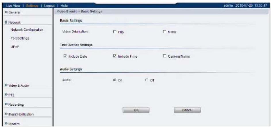
Basic Settings
Basic settings pertain to simple live-view tweaks. These parameters can be found under Video & Audio> Basic Settings.
Video Orientation
In certain mounting situations, the default video output may not be oriented correctly. This setting allows you to change the orientation of the output video.
- Flip - flips the image vertically.
- Mirror - flips the image horizontally.
Text Overlay Setting
The text overlay involves is the text displayed in the black bar at the top of the output screen. You can display multiple text messages at the same time. (Only the camera name will display if the resolution is 160 x 120).
- Include Date - Displays the current date.
- Include Time - Displays the current time.
• Camera Name - Displays the name of the camera.
Audio Settings
Select the desired button to turn audio from the camera on or off.
Click OK to save or Cancel to abort the changes before you leave the page.
Image Appearance
These settings, found under Video & Audio> Image Appearance, deal with the video output of the camera. There are two tabs, Image Attributes and Sensor Configuration, as well as Advanced Settings.
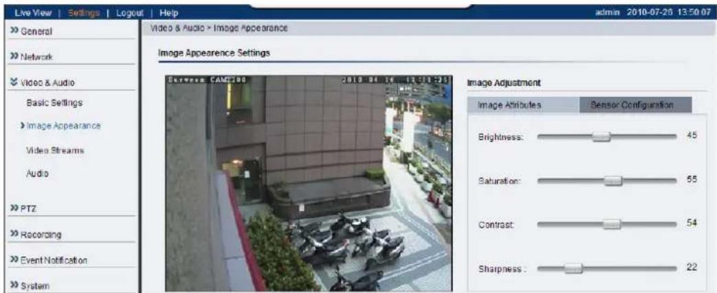
Image Attributes
These parameters deal with the image lighting and color. All parameters are values ranging from (0) to (100). Dragging the slider to the right increases the value, while dragging to the left lowers the value. The adjustments will be displayed in real-time in the window to the left of the sliders.
- Brightness - Adjusts the perceived light intensity of the image.
Note: In certain situations, the sensor may experience banding issues. In these cases, please turn raise the brightness.
- Saturation - Adjusts the colorfulness of a color relative to its own brightness.
- Contrast - Adjusts the overall difference in the light vs dark areas.
- Sharpness - Adjusts the edge contrast of the image.
Sensor Configuration
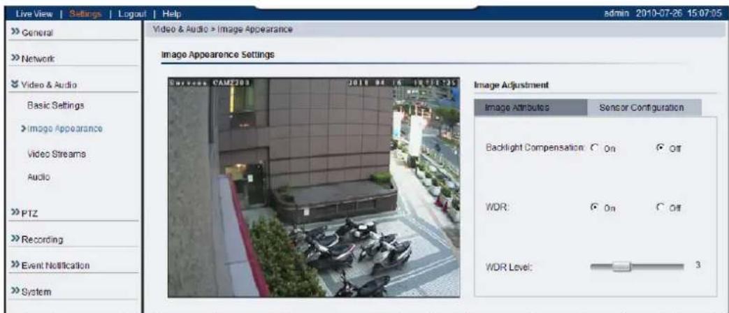
The Sensor Configuration can be accessed by clicking on the tab to the right of the Image Attributes tab. The following parameters can be changed:
- Backlight Compensation - Backlight compensation adjusts video gain to automatically correct the exposure of objects that are strongly backlit. This brightens the image, at the cost of overexposing areas of high illumination. - WDR - Specifies if the wide dynamic range (WDR) function is activated. If activated, the WDR function will attempt to preserve detail at contrast extremes.
○ WDR Level - Specifies the WDR correction level ranging from 1 (least) to 10 (most).
Advanced Settings
The Advanced Settings allow you to make changes to the following parameters:
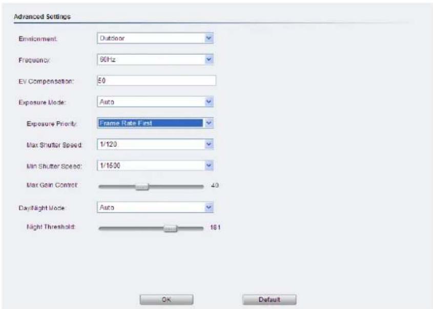
- Frequency - Reduces flickering caused by the difference in frequency of the system and the environment lighting. The user can choose to compensate for 50Hz or 60Hz lighting.
Note: In certain situations, the sensor may experience banding issues. In these cases, please turn the flickerless feature on.
- EV Compensation - Sets how much additional exposure the user wishes to adjust from the automatically calculated value: 0 to 100.
- Exposure Mode - Sets how the camera captures images. Longer shutter times allow more light into the sensor, resulting in a cleaner picture, however longer shutter times can result in motion blur.
- Auto - The camera will automatically change the shutter speed and gain to balance between image quality and frame rate when there is insufficient light to preserve both.
- Exposure Priority - The priorities for the auto exposure balancing are determined in the dropdown.
- Image Quality First - The camera lowers the shutter speed to preserve the gain level set by the Gain Control slider.
- Frame Rate First - The camera will raise the gain rate to preserve the shutter speed specified in the Shutter Speed dropdown while preserving the gain level set by the Gain Control slider.
- Max Shutter Speed - users can choose the Max Shutter Speed from 1/30, 1/60, 1/120, 1/1000 and 1/10000.
- Min Shutter Speed - users can choose the Min Shutter Speed from 1/30, 1/60, 1/120, 1/250, 1/500, 1/750, 1/1000, 1/1500, 1/2000, 1/10000 and 1/100000.
Note: (1) After selecting Frame Rate First, a new parameter - Environment will appear. In this category, Indoor/Outdoor Mode can be chosen. (2) The default setting of Environment and minimum shutter speed for 3365/4365/4360 is Outdoor (1/1000).
- Main Gain Control - The gain control slider determines the maximum amount of gain allowed.
- Manual - This setting allows users to specify a shutter speed that the camera will not go below, and gain amount that the camera will not exceed.
- Day/Night Mode - Sets the day (color) and night (black and white, IR cut filter off where applicable.) Night mode sacrifices color information to produce a clear picture with less light.
- Auto - The camera will switch automatically between modes once a certain amount of light is reached.
- Night Threshold - The threshold which the camera will switch between modes.
○ Day mode - Forces day mode.
○ Night mode - Forces night mode.
- Schedule for day mode - Allows the user to set a time for day/night transitions.
- From: - The time, in hours and minutes, when the camera will be in day mode.
- To: - The time, in hours and minutes, when the camera will switch to night mode.
Click OK to save or Cancel to abort the changes before you leave the page.
Video Streams
The configuration for video streams, including resolution, frame rate and image quality parameters can be found under Video & Audio> Video Streams.
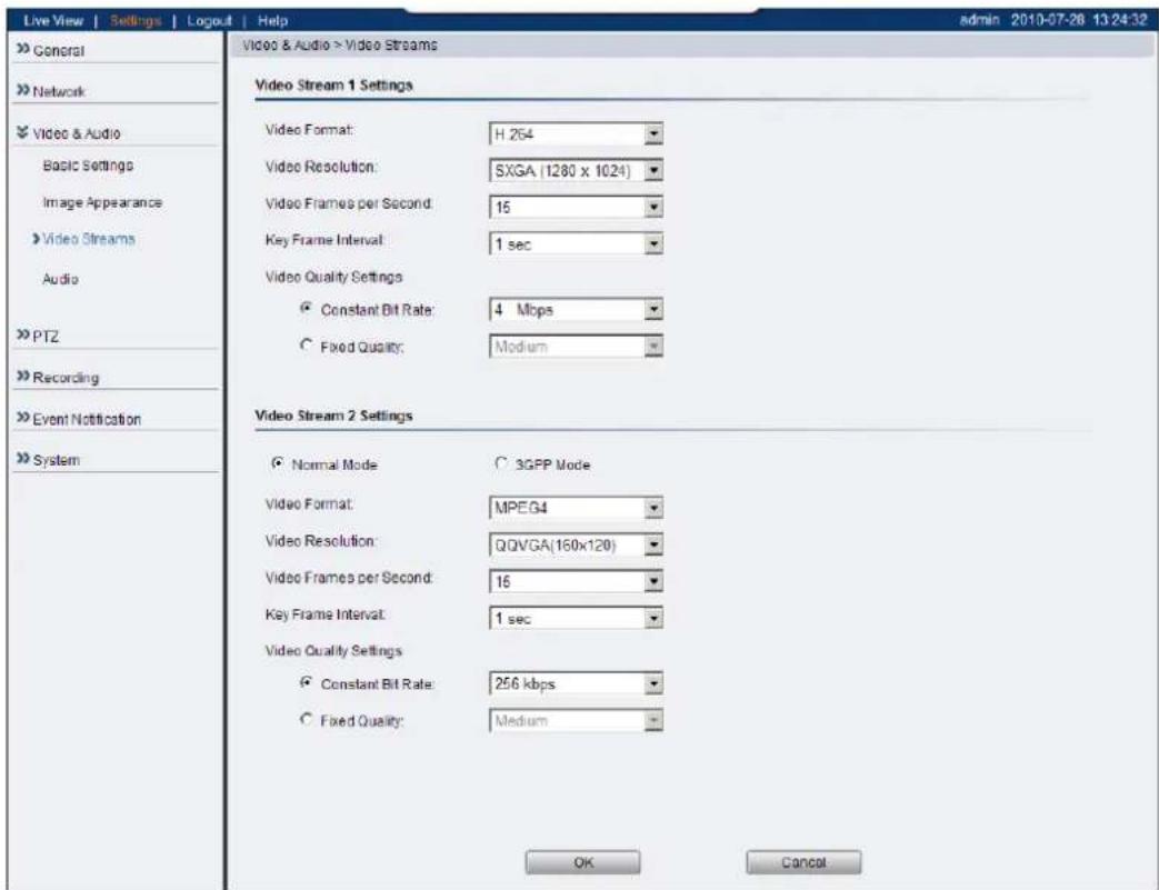
The page is split into settings for 2 streams. Common settings are:
• Video format - The compression format for the video stream.
- H.264 - Provides the best compression, and clear picture, but is processor intensive.
- MPEG4 - Provides more compression that MJPEG, but loses picture quality.
- MJPEG - Provides minimal compression, with the best picture quality. Each frame is stored as a discrete JPEG. This option is only available in Stream 1.
- Video Resolution - Sets the resolution of the video output. The following options are available: 1536P (2048 x 1536, Stream 1 only), 1080P (1920 x 1080, Stream 1 only), SXGA (1280 x 1024, Stream 1 only), 720P (1280 x 720, Stream 1 only), VGA (640x480), QVGA (320x240), QQVGA (160x120, Stream 2 and MPEG4 only).
- Video Frames per Second - Sets the number of frames per second. 1, 3, 5, 10, 15, 20, 25, 30 FPS are possible values.
- Key Frame Interval - Sets the period between minimally compressed recovery frames that don't require other video frames to decode. 1/4s, 1/2s, 1s, 2s, 3s, and 4s are possible values.
• Video Quality Settings - Sets the quality of the video image.
- Constant Bit Rate - In this mode, the camera will maintain a constant bit rate output, regardless of video quality. Bit rates available are dependent on the video resolution chosen, and range from 32 kbps to 10 Mbps.
- Fixed quality - In this mode, the camera will attempt to maintain a constant quality output, up to a maximum bandwidth of 10 Mbps.
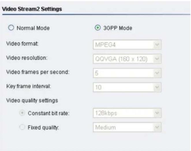
There are 2 modes in the Video Stream 2 Settings:
• Normal Mode - All parameters may be changed.
- 3GPP Mode - All parameters will default to settings that are compatible with mobile viewing. The default in this case is 5fps QQVGA video, with MPEG4 compression at 128kbps and 10 seconds between key frames. None of the parameters can be changed.
Click OK to save or Cancel to abort the changes before you leave the page.
Audio Settings
The audio settings, under Video & Audio> Audio Settings, contain parameters dealing with audio coming from the cameras built in mic, or an external microphone.
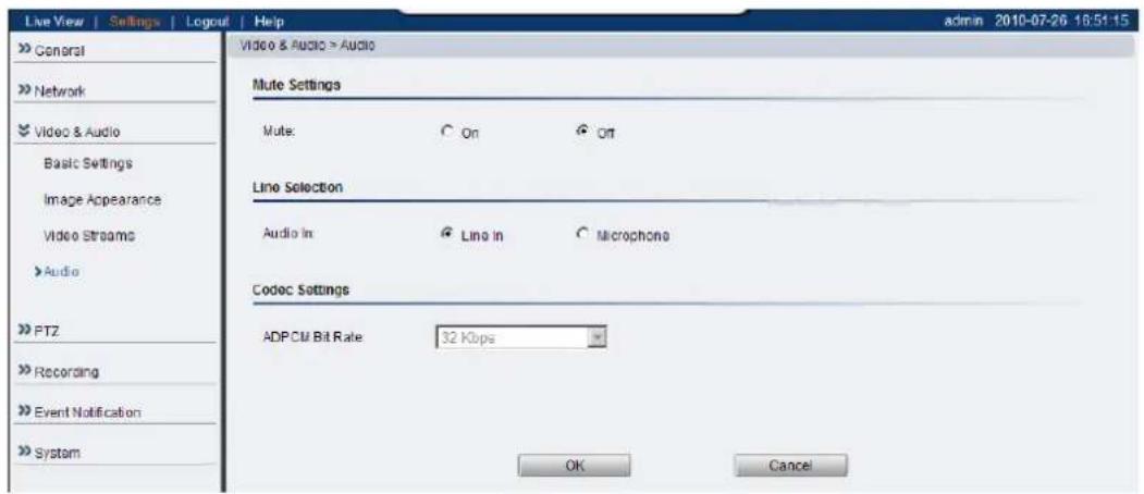
- Mute - Selects whether or not to mute the incoming audio from the camera.
- Audio In - Selects the source for the camera audio feed. Line In specifies an external source connected to the camera's line-in port, while Microphone is the camera's internal microphone.
- ADPCM Bit Rate - Adaptive differential pulse-code modulation (ADPCM) is a method for digitally encoding audio signals. Only one bit rate, 32 Kbps, is currently supported. Audio will be encoded at this bit rate.
Click OK to save or Cancel to abort the changes before you leave the page.
Note: Only Stream 1 supports audio.
Recording
The Recording menu, Settings> Recording, deals with recording settings and managing recorded video files.
Recording Basic Settings
Recording basic settings, Recording> Recording Basic Settings are parameters which deal with the recording location and scheduling.
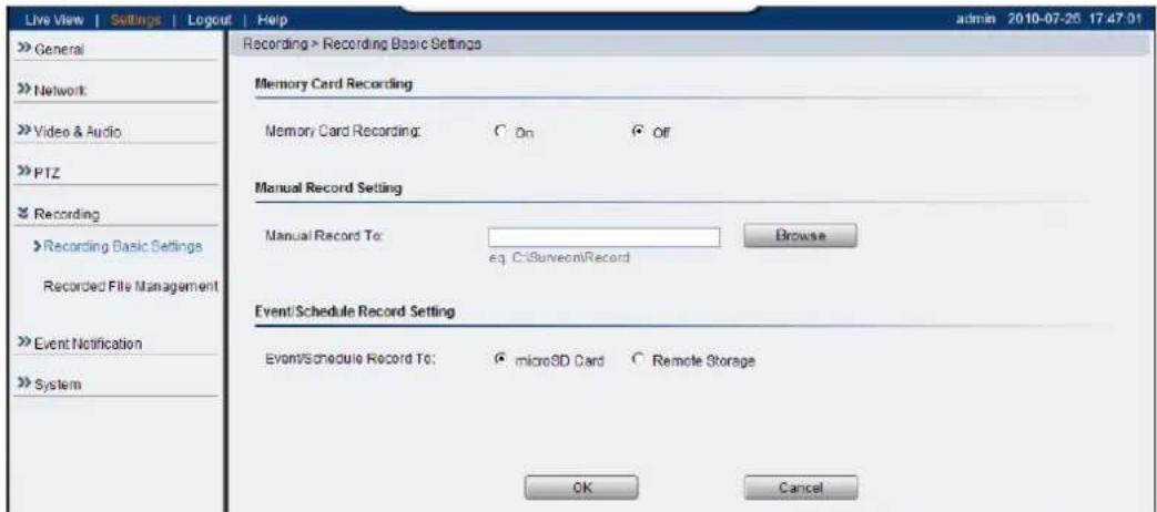
The following parameters can be configured within this menu:
- Memory Card Recording - When turned on, video will automatically be recorded onto the microSD card if the network connection is lost. When a network connection is re-established, recording will switch back to the remote destination. If this feature is turned off, there will be no recording at all when if network connection is lost.
- Manual Record To: - Defines the path for manual recording. Screenshots and user recordings will be saved in this location.
- Event/Schedule Record To: - Allows the user to set the destination for event or scheduled recording. Event and scheduled recording settings are found under Settings> Event Notification.
Click OK to save or Cancel to abort the changes before you leave the page.
Recorded File Management
This section, located at Recording> Recorded File Management allows users to manage videos recorded on the microSD cards.
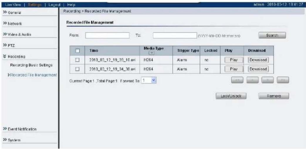
Locating Video Files
To locate video files from a specific time frame, enter a begin and end time in the From: and To: fields below, and click Search.
Each video file will have an entry containing:
- Time - The time the video was recorded, also the filename of the entry: YYYY_MM_DD_HH_MM_SS.avi
• Media Type - The encoding/compression method - Trigger Type - What type of action triggered this recording eg. if it was alarm recording or scheduled recording.
- Locked - The lock state of the alarm.
The video records located will be split into pages. The information on these
- << - Click to go to the first page of the recorded files list.
- < - Click to go to the previous page of the recorded files list.
-
- Click to go to the next page of the recorded files list.
-
- Click to go to the last page of the recorded files list.
- Forward To: - This dropdown can be used to skip to a page number.
You may also narrow the entries displayed by clicking on the Media Type column. This will give you the option of choosing All, H264, MPEG4, or MJPEG types. The system will only show video files of the format selected.
Managing Video Files
Once you have located the video files of interest you may select them by checking the box in the leftmost column of the entry. You can also select all displayed entries by checking the box in the header row.
There will be two buttons in each entry:
- Play - Plays the video file in local helper application.
- Download - Downloads video files. Select one or more video files and click Download; Choose location to save the video file(s) onto your local PC.
Other actions that you can perform:
- Lock/Unlock - Locks/Unlocks video files. Locked files cannot be removed. Select one or multiple video files and click Lock/Unlock. When a file is locked, the Locked status will display yes.
- Remove - Manually deletes stored video files. Select one or more video files and click Remove to delete the file(s).
Click OK to save or Cancel to abort the changes before you leave the page.
Note: The video files shown in Recorded File Management are files stored in the microSD card. You can also record live video by clicking the record button in the Live View screen, which will be stored directly into your local computer, and are not managed by this function. Please refer to the section on Manual Record for more information on this functionality.
Event Notification
Event Notification settings, found under Settings> Event Notification, deal with the event detection, scheduled recording, and notification abilities of the camera.
Event Server
The event server, which can be configured under Event Notification> Event Server, is the communications center of the camera. This section deals with the configuration of E-mail and FTP notifications, as well as remote recording.
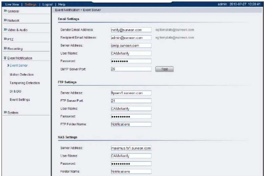
Email Settings
Email settings are used to configure e-mail notifications.
- Sender Email Address - The return e-mail address for notifications. This should be your notification address.
- Recipient email address - The e-mail address notification emails will be sent to. Only one email address can be entered.
• Server address - The IP or address of the e-mail server. - User Name - The user name of the notifications e-mail account.
- Password - The password of the e-mail account.
- SMTP Server Port - the SMTP port of the email server; Default 25.
- Test - Click this button to send a test email. E-mails will only be sent if all parameters are entered correctly.
FTP Settings
FTP settings are used to configure recording to a remote location via the file transfer protocol.
• Server Address - The address of the FTP server.
- FTP Server Port - The port number of the FTP server; Default 21.
- User Name - The user name of the FTP account.
- Password - The password of the FTP account.
- FTP Folder Name - The name of the folder on the FTP site which video files will be stored in.
NAS Settings
NAS settings are used to configure recording to network attached storage.
• Server Address - The address of the NAS server.
- User Name - The user name of the NAS account.
- Password - The password of the NAS account.
- Folder Name - The name of the CIFS account folder on the server.
Click OK to save or Cancel to abort the changes before you leave the page.
Motion Detection
The motion detection functionality of the camera can be found under Event Notification> Motion Detection.
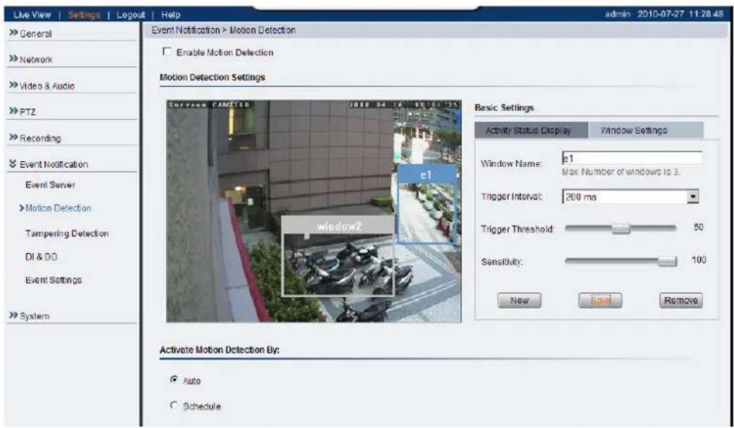
Motion Detection Window Management
To detect motion, first a detection window must be created. First click the Window Settings tab to enter the window configuration, and click New to add a new detection window. A maximum of 3 motion detection windows can be added. Each new window will be created with a default name Window N, where N is the number of the window. After creating the window, clicking it will select the window. You can drag and resize the window using your mouse. You can also change the following parameters:
- Window Name - The name of the motion detection window.
- Trigger Interval - The time interval between motion triggers. Options available are: 200 ms, 400 ms, 800 ms, and 1000 ms.
- Trigger Threshold - The percentage change in the window before a motion alarm is triggered.
- Sensitivity - The sensitivity of the motion box.
Click Save to save all settings. Settings of existing windows can also be changed by selecting the window and changing the settings. To delete a window, select a window in and click Remove.
After windows are set, you can activate motion detection by checking the Enable Motion Detection box.
Activating and Scheduling Motion Detection
Motion detection is activated by checking the Enable Motion Detection box.
Activate Motion Detection By: denotes when motion detection will be triggered as an event.
- Auto - As long as Enable Motion Detection is checked, an event is triggered.
- Schedule - Selecting this option allows to manually schedule the times
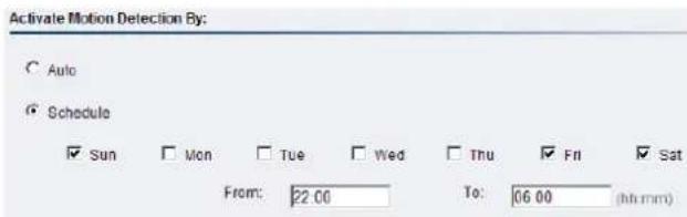
motion detection will be active. Select the days of the week that Motion Detection is active by checking the corresponding boxes, and fill in a start time and end time for motion detection in the From: and To: boxes.
Click OK to save or Cancel to abort the changes before you leave the page.
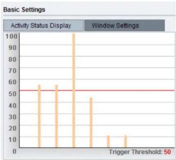
Triggering a Motion Event
The video displaying on the window is the live streaming video. The Activity Status Display tab displays the amount of motion detected in a selected window. By raising the Sensitivity of the window the motion values for a given motion, which are in shown in yellow, will be higher. When the motion value reaches or crosses the Trigger Threshold, denoted by the red line, a motion event will be triggered. Motion alarm handling and notifications can be configured under Event Settings.
bar
Basic Settings Activity Status Display Window Settings Trigger Threshold: 50 | Activity Status Display | Value | | :--- | :--- | | 1 | 57 | | 2 | 57 | | 3 | 102 | | 4 | 46 | | 5 | 14 | | 6 | 14 |DI & DO
Digital Input (DI) and Digital Output (DO) stand are used for event triggering. The camera has 1 DO and 2 DI ports. Settings for these ports can be found under Event Notification> DI & DO. Conditions for DI and DO triggering, as well as notifications for can be set under Event Settings.
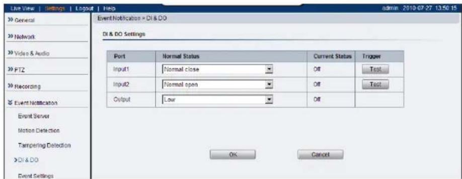
Digital Input
The two inputs are listed as Input1 and Input2 and connect to external circuits such as window break detectors. These inputs can be tested by clicking the Test button in the input entry.
Each input has a Normal Status:
- Normal Open - the DI requires a low voltage input, with the following configuration.
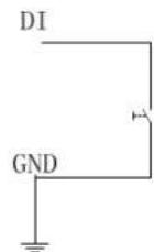
It is triggered when it does not receive this input.
- Normal Close - the DI requires a high voltage input (+12V), with the following configuration.
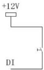
It is triggered when it does not receive this input.
- Off - DI inputs are closed at all times. The camera will not respond to any signals on this DI.
Digital Output
The camera can also be configured to send signals through the digital output.
Each output has a Normal Status:
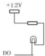
- High - DO outputs a high voltage when triggered, and is connected to the output circuit in the following manner:
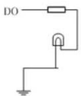
- Low - DO acts as a ground when triggered, and is connected to the output circuit in the following manner:
- Off - Closes DO output; no signals will be sent.
Click OK to save or Cancel to abort the changes before you leave the page.
Event Settings
Event settings deal with alarm handling and notification, as well as feature scheduling. These settings can be found under the Event Notification> Event Settings menu.
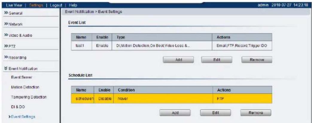
The event handler is rule based. There are lists for both two types of rules:
- Event List - Contains rules based on triggered events such as motion detection or DI triggers.
- Schedule List - Contains time-based rules.
Each rule has an action list. When the conditions for rule are met, the actions specified by the rule are carried out. Users may perform the following actions in both Event and Schedule lists:
- Add - Clicking on the Add button adds a new rule to a list.
-
Select - Clicking on an existing rule selects the rule, highlighting it in yellow.
-
Edit - A selected rule may be edited by clicking on the Edit button.
Delete - A selected rule may be deleted by clicking on the Delete button.
Adding/Editing an Event Rule
The Add and Edit screens contain the following triggering actions:
Note: If editing a rule that has not been triggered, the rule will not be triggered after until after editing is complete. If the rule is triggered, any changes will not be applied until the current trigger is resolved.
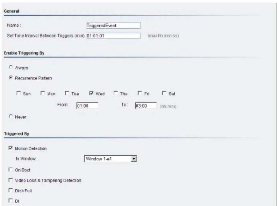
General
The following general fields should be filled in:
- Name - Specifies the name of the Event.
- Minimum time interval between triggers - The time frame in which a subsequent trigger of the same event will be ignored (maximum 23:59:59).
Enable Triggering By
The next step is to specify the frequency of trigger response. 3 options are available:
• Always - The default setting; Triggers event when conditions are met.
- Recurrence Pattern - Enables triggering only if conditions are met during a specified time period. To specify the period, select the days of the week that the trigger is active by checking the corresponding
boxes, and fill in a start time and end time for motion detection in the From: and To: boxes.

- Never - The event is never triggered.
Enable Triggering By
After the frequency is selected, triggering conditions can be set. Multiple conditions can be set at once. Available options include:
- Motion Detection - Trigger when motion is detected.
- In Window - Specifies the detection window that will trigger the event.
Please refer to the section on Motion Detection for details.
- On Boot - Trigger when camera reboots.
- Video Loss & Tampering Detection - Trigger when video signal is lost or tampering is detected. Please refer to the section on Tampering Detection for more detail.
- Disk Full - Trigger when the SD disk installed in the camera is full.
- DI - Trigger when a DI trigger occurs. For more information please refer to the section on DI & DO.
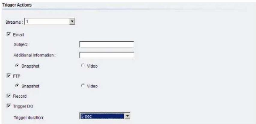
When Triggered
The actions to take when trigger conditions are met are configured here.
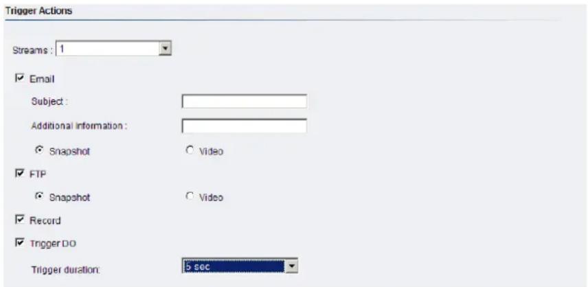
The following options are available:
- Streams - Selects the stream from which the snapshot or recording will be obtained.
-
Email - E-mails notifications to the email address specified in the Event Server settings. If this option is chosen, fill in the following:
-
Subject - The subject line of the notification e-mail.
○ Additional Information - Contents of the notification e-mail. - Snapshot/Video Clip - Choose to send a snapshot or video attachment from 5s before to 30s after the trigger.
- FTP - uploads a snapshot or video clip to a FTP location specified in the Event Server settings.
- Snapshot/Video Clip - Choose to upload a snapshot or video file from 5 seconds before to 30 seconds after the trigger. Files are sent as attachments.
- Record - Records video to the server specified in the Event Server settings and the microSD card when triggered. The video clip stored on both remote storage server and local storage is a video file 35 seconds in length (5 seconds before and 30 seconds after the trigger)
- Trigger DO - A Digital output signal is sent when triggered.
○ Trigger Duration - The length of time that the DO signal is sent. Options are 1, 2, 5, 10, 20 or 30 seconds. For more information please refer to the section on DI & DO.
Click OK to save or Cancel to abort the changes before you leave the page.
Adding/Editing a Scheduled Rule
The Add and Edit screens contain the following actions:
Note: If editing a rule that has not been triggered, the rule will not be triggered after until after editing is complete. If the rule is triggered, any changes will not be applied until the current trigger is resolved.
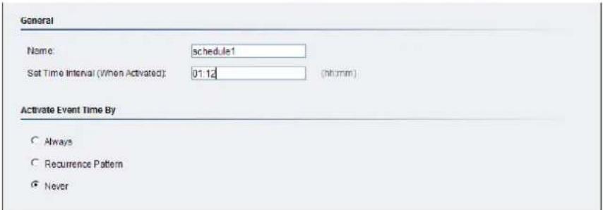
General
The following general fields should be filled in:
- Name - Specifies the name of the Event.
- Set Time Interval (When Activated) - The trigger time of the event (00:00 to 23:59).
Enable Triggering By
The next step is to specify the frequency of trigger response. 3 options are available:
• Always - The default setting; Triggers event when conditions are met.
- Recurrence Pattern - Enables triggering only if conditions are met during a specified time period. To specify the period, select the days of the week that the trigger is active by checking the corresponding boxes, and fill in a start time and end time for motion detection in the

From: and To: boxes.
- Never - The event is never triggered.
When Triggered
The actions to take when trigger conditions are met are configured here.
The following options are available:
- Streams - Selects the stream from which the snapshot or recording will be obtained.
- Email - E-mails notifications to the email address specified in the Event Server settings. If this option is chosen, fill in the following:
- Subject - The subject line of the notification e-mail.
○ Additional Information - Contents of the notification e-mail. - Snapshot/Video Clip - Choose to send a snapshot or video attachment from 5s before to 30s after the trigger.
- FTP - uploads a snapshot or video clip to a FTP location specified in the Event Server settings.
- Snapshot/Video Clip - Choose to upload a snapshot or video file from 5 seconds before to 30 seconds after the trigger. Files are sent as attachments.
- Record - Records video to the server specified in the Event Server settings and the microSD card when triggered. The video clip stored on both remote storage server and local storage is a video file 35 seconds in length (5 seconds before and 30 seconds after the trigger)
- Trigger DO - A Digital output signal is sent when triggered.
○ Trigger Duration - The length of time that the DO signal is sent. Options are 1, 2, 5, 10, 20 or 30 seconds. For more information please refer to the section on DI & DO.
Click OK to save or Cancel to abort the changes before you leave the page.
System
The system settings, which deal with hardware and firmware parameters, logs, and configuration lists, can be found under Settings> System.
MicroSD Card Management
Surveon cameras can all access MicroSD class 4/6 cards for offline video storage and upgrade purposes. MicroSD installed in the camera can be managed under System> MicroSD Card Management.
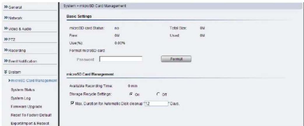
The status of the current microSD card can be obtained under Basic Settings:
- MicroSD card Status - If a readable card is present this will show ready, otherwise it will display no.
• Total Size - The size of the card.
• Free - The total space left on the card.
• Used - The occupied space on the card.
• Use(%) - The percentage of the card that has been used.
The user may also enter the administrator password if necessary and click Format to format the microSD card.
In MicroSD Card Management:
- Available Recording Time - Calculates how much recording time is available based on current settings.
- Storage Recycle Settings - Turning the function On will clear the microSD card once it is full.
- Max Duration for Automatic Disc cleanup _ days - If storage recycling is activated, the card will be cleared when this number of days has elapsed. (100 days max. Locked files will not be cleared).
Click OK to save or Cancel to abort the changes before you leave the page.
System Status
The camera status can be found under System> System Status.
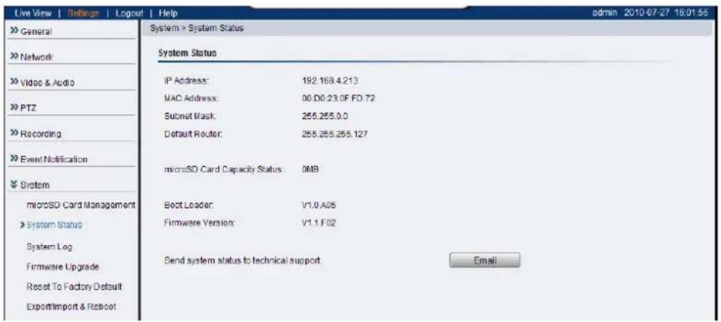
This section displays useful system information including:
• Network Configuration defined manually or obtained from DHCP
-
IP Address
○ MAC Address
○ Subnet Mask
Default Router address -
microSD Card Capacity
• Camera System Information
- Boot Loader Version
- Firmware Version
Clicking on the Email button will send the system status information out to the notification e-mail address specified in Event Server for troubleshooting or reference purposes.
System log
The system log, System> System Log, provides a log for system messages and events. The log lists important information such as login information, changes to camera settings (both successful and unsuccessful), triggered events, and error messages.
This information can be very useful in the event of a camera failure or unauthorized entry.
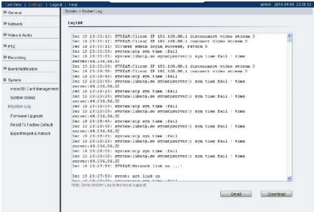
Clicking Email will send the log out as an email the notification e-mail address specified in Event Server; Clicking Download will begin the browser download process to download the log to the local PC.
Firmware Upgrade
In certain cases, improvements to the camera firmware will be made to improve the image quality or enhance the usability of the camera. These upgrades will be made available via Surveon support or our website www.surveon.com. Once you have obtained a new firmware file, firmware upgrades can be performed under System> Firmware Upgrade.
There are 2 ways to upgrade the firmware:
- Upgrading through firmware stored locally on a PC
- Upgrading through firmware stored in a microSD card
If upgrading through firmware stored locally, enter the path of the file in the provided field or click Browse to find the file.
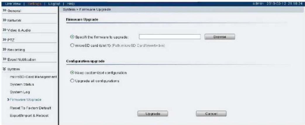
Select Keep customized configuration to keep current configuration settings, or Upgrade all configurations to clear all settings back to factory defaults.
Click Upgrade to start the upgrade. Upon completion of firmware upgrade, the camera will reboot (you will be logged off). During the firmware upgrade, the LED indicator in front of the camera will show steady amber. When the LED indicator turns green, the firmware upgrade is complete.
Click Cancel to exit without upgrading.
Micro SD card upgrades will be supported in future phases. To perform a firmware upgrade from the MicroSD card, copy the new firmware onto the MicroSD card, and reboot (cycle camera power) or reset the camera. The camera will automatically detect the firmware and perform the upgrade. Remove the MicroSD card and delete the firmware when the upgrade is complete.
Reset to Factory Default
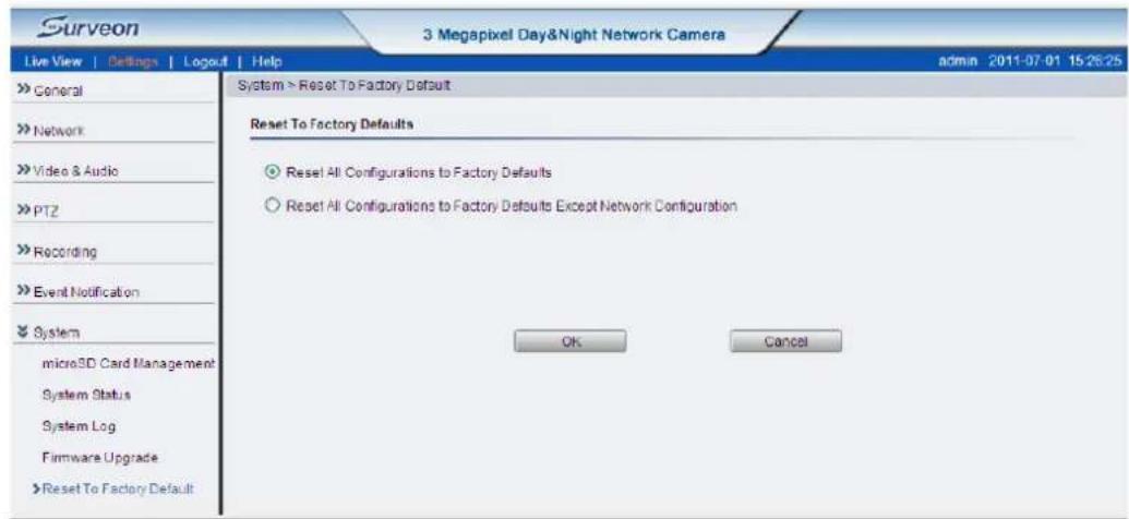
Camera resets can be performed under System> Reset To Factory Default.
There are 2 types of reset. You can either reset all settings and configurations, or you can choose to keep the Network configuration, and reset all other settings and configurations.
Click OK after choosing a reset option to perform a reset.
Alternately, you may press the “Reset” button on the bottom of the camera to perform a complete reset of the camera (no configurations retained). To reset the camera by pressing the “Reset” button on the bottom of the camera, press and hold the “Reset” button for 3 seconds. During this time, the LED indicator in front of the camera will blink in red.
Export/Import & Reboot
In certain situations it may be necessary to restart your network camera (network settings changed, DHCP added, etc). The settings under System>
Export/Import & Reboot allow you to restart the camera.
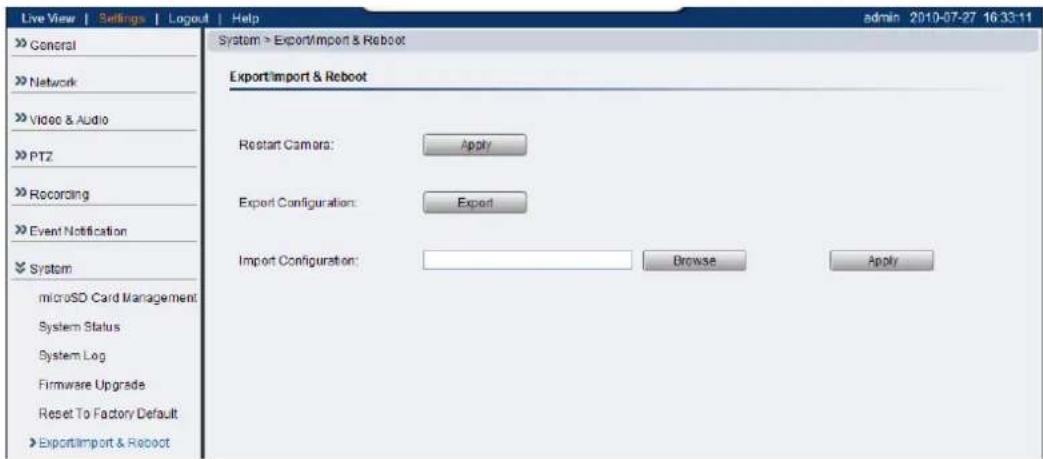
This menu also contains options to export configuration details (for backup or replication purposes), as well as import configuration details. The following options are available:
- Restart Camera - Resets the camera when Apply is clicked.
- Export Configuration - Export the camera's settings and configurations by clicking Export, this will start a browser dialogue to download the configuration.
- Import Configuration - Imports previously exported camera settings. The field should contain the path for the camera configuration file. Click Browse: to browse your PC for the configuration file. Click Apply to import the settings.