PLC-755M - Video projector SANYO - Free user manual and instructions
Find the device manual for free PLC-755M SANYO in PDF.

User questions about PLC-755M SANYO
0 question about this device. Answer the ones you know or ask your own.
Ask a new question about this device
Download the instructions for your Video projector in PDF format for free! Find your manual PLC-755M - SANYO and take your electronic device back in hand. On this page are published all the documents necessary for the use of your device. PLC-755M by SANYO.
USER MANUAL PLC-755M SANYO
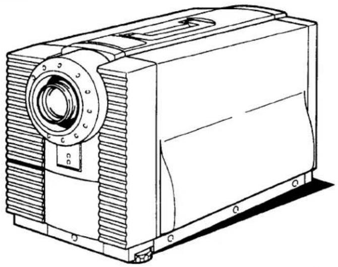
Super Brightness LCD Data-Grade Projector
MODEL PLC-750M
PLC-755M
natural_image
Technical line drawing of a mechanical device with gear and housing (no text or symbols)Owner's Manual
INFORMATION TO THE USER
NOTE: This equipment has been tested and found to comply with the limits for a Class A digital device, pursuant to Part 15 of the FCC Rules. These limits are designed to provide reasonable protection against harmful interference when the equipment is operated in a commercial environment. This equipment generates, uses, and can radiate radio frequency energy and, if not installed and used in accordance with the instruction manual, may cause harmful interference to radio communications. Operation of this equipment in a residential area is likely to cause harmful interference in which case the user will be required to correct the interference at his own expense.
TO THE OWNER
As the owner of a new Data LCD Color Projector, you are probably eager to try out your new projector. Before you do, we suggest that you spend a little time reading this manual to familiarize yourself with the operating procedures, so that you will receive maximum enjoyment from the many features included on your new projector.
This owner's manual will acquaint you with your projector's features. Reading it will help us too. Through the years, we have found that many service requests were not caused by problems with our projectors. They were caused by problems that could have been prevented, if the owner had followed the instructions in the manual.
You can often correct operating problems yourself. If your projector fails to work properly, locate the operating problem in the Helpful Hints Chart on page 25 and try the solutions marked for each problem.
SAFETY PRECAUTIONS
WARNING:
TO REDUCE THE RISK OF FIRE OR ELECTRIC SHOCK, DO NOT EXPOSE THIS APPLIANCE TO RAIN OR MOISTURE.
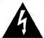
The new Data LCD Color Projector has a grounding-type AC line plug. This is a safety feature to be sure that the plug will fit into the power outlet. Do not try to defeat this safety feature.
Intense light source. Do not stare directly into the projection lens as possible eye damage could result. Be especially careful that children do not stare directly into the beam.
If the new Data LCD Color Projector will not be used for an extended time, unplug the new Data LCD Color Projector from the power outlet.
READ AND KEEP THIS OWNER'S MANUAL FOR LATER USE.
CAUTION
RISK OF ELECTRIC SHOCK DO NOT OPEN

CAUTION: TO REDUCE THE RISK OF ELECTRIC SHOCK, DO NOT REMOVE COVER (OR BACK). NO USER-SERVICEABLE PARTS INSIDE. REFER SERVICING TO QUALIFIED SERVICE PERSONNEL.

THIS SYMBOL INDICATES THAT DANGEROUS VOLTAGE CONSTITUTING A RISK OF ELECTRIC SHOCK IS PRESENT WITHIN THIS UNIT.

THIS SYMBOL INDICATES THAT THERE ARE IMPORTANT OPERATING AND MAINTENANCE INSTRUCTIONS IN THE OWNER'S MANUAL WITH THIS UNIT.
IMPORTANT SAFETY INSTRUCTIONS
All the safety and operating instructions should be read before the product is operated.
Read all of the instructions given here and retain them for later use. Unplug this projector from AC power supply before cleaning. Do not use liquid or aerosol cleaners. Use a damp cloth for cleaning.
Do not use attachments not recommended by the manufacturer as they may cause hazards.
Do not place this projector on an unstable cart, stand, or table. The projector may fall, causing serious injury to a child or adult, and serious damage to the projector. Use only with a cart or stand recommended by the manufacturer, or sold with the projector. Wall or shelf mounting should follow the manufacturer's instructions, and should use a mounting kit approved by the manufacturer.
Do not expose this unit to rain or use near water... for example, in a wet basement, near a swimming pool or the like.
Slots and openings in the cabinet and the back or bottom are provided for ventilation, to insure reliable operation of the equipment and to protect it from overheating.
The openings should never be covered with cloth or other material, and the bottom opening should not be blocked by placing the projector on a bed, sofa, rug, or other similar surface. This projector should never be placed near or over a radiator or heat register.
This projector should not be placed in a built-in installation such as a bookcase unless proper ventilation is provided.
This projector should be operated only from the type of power source indicated on the marking label. If you are not sure of the type of power supplied, consult your authorized dealer or local power company.
Do not overload wall outlets and extension cords as this can result in fire or electric shock. Do not allow anything to rest on the power cord. Do not locate this projector where the cord will be abused by persons walking on it.
Never push objects of any kind into this projector through cabinet slots as they may touch dangerous voltage points or short out parts that could result in a fire or electric shock. Never spill liquid of any kind on the projector.
Do not attempt to service this projector yourself as opening or removing covers may expose you to dangerous voltage or other hazards. Refer all servicing to qualified service personnel.
Unplug this projector from wall outlet and refer servicing to qualified service personnel under the following conditions:
a. When the power cord or plug is damaged or frayed.
b. If liquid has been spilled into the projector.
c. If the projector has been exposed to rain or water.
d. If the projector does not operate normally by following the operating instructions. Adjust only those controls that are covered by the operating instructions as improper adjustment of other controls may result in damage and will often require extensive work by a qualified technician to restore the projector to normal operation.
e. If the projector has been dropped or the cabinet has been damaged.
f. When the projector exhibits a distinct change in performance-this indicates a need for service.
When replacement parts are required, be sure the service technician has used replacement parts specified by the manufacturer that have the same characteristics as the original part. Unauthorized substitutions may result in fire, electric shock, or injury to persons.
Upon completion of any service or repairs to this projector, ask the service technician to perform routine safety checks to determine that the projector is in safe operating condition.
This projector is equipped with a grounding type AC line plug. Should you be unable to insert the plug into the outlet, contact your electrician. Do not defeat the safety purpose of this grounding type plug.
Follow all warnings and instructions marked on the projectors.
For added protection for the projector during a lightning storm, or when it is left unattended and unused for long periods of time, unplug it from the wall outlet. This will prevent damage due to lightning and powerline surges.

natural_image
Silhouette of a person pushing a ladder with boxes, enclosed in a circular frame (no text or symbols)An appliance and cart combination should be moved with care. Quick stops, excessive force, and uneven surfaces may cause the appliance and cart combination to overturn.
TABLE OF CONTENTS
PAGE
DESCRIPTION 5
CONNECTING THE PROJECTOR 6-11
SETTING-UP THE PROJECTOR....12
PICTURE ADJUSTMENTS 21-22
AIR FILTER CARE AND CLEANING 23
LAMP REPLACEMENT/TEMPERATURE INDICATORS 24
HELPFUL HINTS-Problems and Solutions 25
TECHNICAL SPECIFICATIONS 26
POWER REQUIREMENTS
Your projector uses nominal input voltages of 100-120 VAC or 200-240 VAC. The projector automatically selects the correct input voltage. The projector is designed to work with single-phase power systems having a grounded neutral conductor. To reduce the risk of electrical shock, do not plug into any other type of power system. Consult your authorized dealer or service station if you are not sure what type of power is supplied to your building.
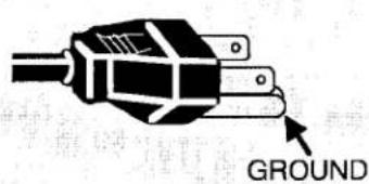
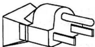
Projector side (Female)
natural_image
Line drawing of a mechanical connector or socket (no text or symbols)AC outlet side (Male)
natural_image
Pure mechanical component diagram without any text, numbers, or symbolsDESCRIPTION
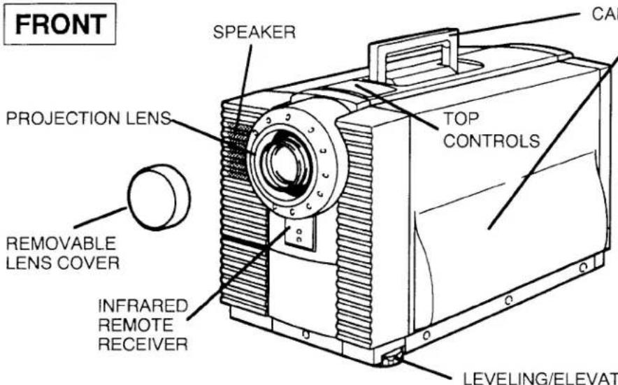
CARRY HANDLE
EXHAUST VENT
CAUTION! HOT AIR!
Air blow from the exhaust vent is hot. Observe the following when handling your projector or choosing a location to install it.
- Keep heat-sensitive objects away from the exhaust port.
- If you set the projector on top of a metallic surface, the surface will become hot because of the hot air exhaust. Be careful when handling.
- Do not touch the cabinet near to the exhaust vent, and especially screws and metallic parts. These parts will become hot while the projector is used.
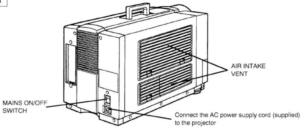
REAR
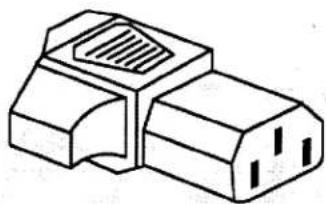
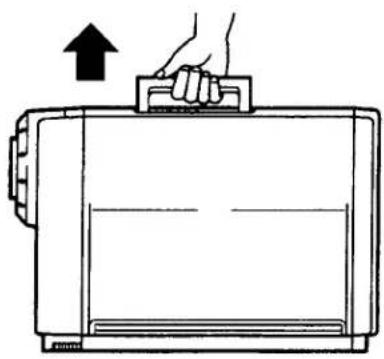
MOVING THE PROJECTOR
Use the carry handle when moving projector.
Replace the lens cover when moving the projector to prevent damage to the lens.
natural_image
Line drawing of a hand pressing down on a rectangular device with an upward arrow (no text or symbols)CONNECTING THE PROJECTOR
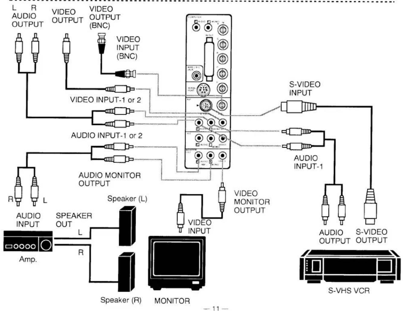
Your projector is equipped with various audio/video inputs and outputs including Computer DB25-pin terminals, Computer Separate input (BNC) and S-VHS video input.
COMPUTER MODE
This projector is compatible with many different types of personal computers: using the adapter Y cable provided, it can be connected directly to any SVGA, VGA and MAC II or compatible computers equipped with APPLE II e, FM-TOWNS (L), CGA, HGC, EGA, MAC SE, FM-TOWNS (640 × 400), FM-TOWNS (640 × 480), MAC LC (12" MONITOR), PC-9801 (640 × 400), PC-9821 (640 × 400), PC-9821 (640 × 480), AT&T, AX-286/386, GENOA 6000, and VESA VS901001. (adapter cable not provided).
NOTE: The projector may not reproduce a proper image for SVGA signal. Because SVGA (800 × 600) image is converted to VGA (640 × 480) image by partial scan, some lines and dots of the image do not appear.
CONNECTING TO THE COMPUTER INPUT/OUTPUT DB25-PIN TERMINAL
Personal computers can be connected to the DB25-pin terminal on the projector.
- Connect the computer to this terminal using the adapter cable (two type of adapter Y cables are provided).
WARNING: For projectors, adapter Y cable provided is designed to reduce RFI (Radio Frequency Interference) emissions. For regulatory compliance reasons, this cable must be used and must not be replaced by any other cable.
Specification of DB25-pin terminal
| Pin No. | Signal | Pin No. | Signal | |
| 1. | Red input (Analog) | 0.7 Vp-p/75 ohm | 14. | Ground |
| 2. | Green input (Analog) | 0.7 Vp-p/75 ohm | 15. | Ground |
| 3. | Blue input (Analog) | 0.7 Vp-p/75 ohm | 16. | Ground |
| 4. | Red output (Analog) | 0.7 Vp-p/75 ohm | 17. | Red input (TTL) |
| 5. | Green output (Analog) | 0.7 Vp-p/75 ohm | 18. | Green input (TTL) |
| 6. | Blue output (Analog) | 0.7 Vp-p/75 ohm | 19. | Blue input (TTL) |
| 7. | ID 0 | 20. | r input (TTL) | |
| 8. | ID 1 | 21. | g input (TTL), CGA Intensity | |
| 9. | ID 2 | 22. | b input (TTL) | |
| 10. | Ground | 23. | NC | |
| 11. | Ground | 24. | Ground | |
| 12. | V. Sync | 25. | Ground | |
| 13. | H. Sync |
Personal computers can be connected to the computer input (Red, Green, Blue, Horiz. Sync. and Vert. Sync.) on the projector.
- Connect the computer to these jacks.
CONNECTING TO THE COMPUTER AUDIO INPUT JACKS
- Connect audio outputs from your computer to these jacks.
- If the audio input of the audio equipment is stereo, be sure to connect the right and left channels to the respective right and left jacks.
- If the audio input of the audio equipment is monaural, connect it to the left jack.
CONNECTING TO THE DIN8 (SERIAL PORT) CONNECTOR
- If you control the projector by computer, you must connect a cable from your computer to this connector.
■ SERIAL PORT
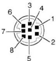
| 1 | RxD |
| 2 | ADB |
| 3 | MUX232 |
| 4 | GND |
| 5 | MUXTTL |
| 6 | TxD |
| 7 | —— |
| 8 | —— |
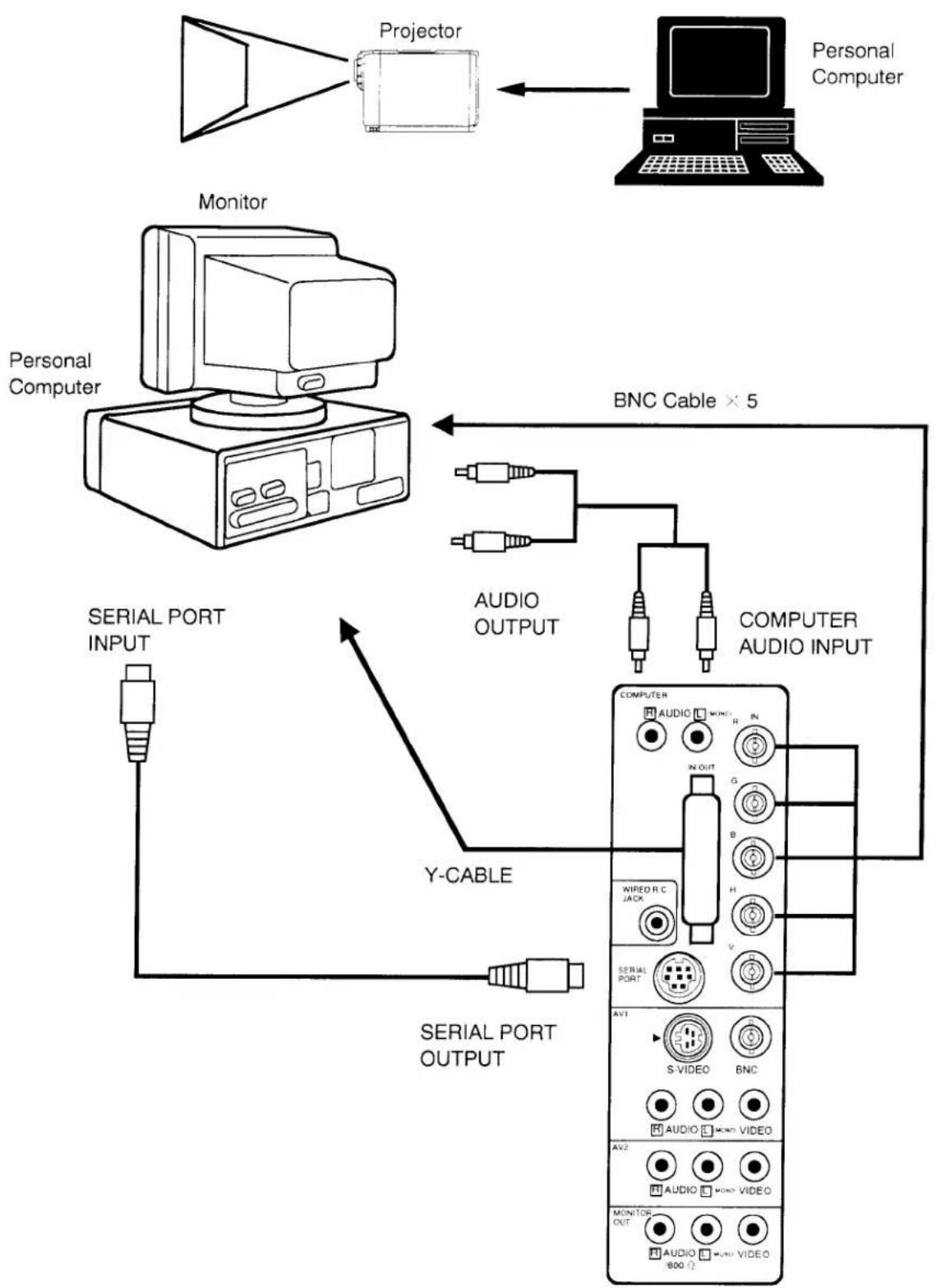
CONNECTING THE PROJECTOR TO A COMPUTER
flowchart
graph TD
    A["Personal Computer"] -->|Projector| B["Projector"]
    B --> C["Projector"]
    D["Monitor"] --> E["Monitor"]
    E --> F["Monitor"]
    F --> G["Personal Computer"]
    G --> H["Personal Computer"]
    H --> I["BNC Cable × 5"]
    I --> J["AUDIO OUTPUT"]
    I --> K["COMPUTER AUDIO INPUT"]
    J --> L["Y-CABLE"]
    K --> L
    L --> M["SERIAL PORT OUTPUT"]
    M --> N["SERIAL PORT INPUT"]
    N --> O["SERIAL PORT INPUT"]
    O --> P["SERIAL PORT OUTPUT"]
    P --> Q["SERIAL PORT INPUT"]
    Q --> R["SERIAL PORT OUTPUT"]
    R --> S["SERIAL PORT INPUT"]
    S --> T["SERIAL PORT OUTPUT"]
    T --> U["SERIAL PORT INPUT"]
    U --> V["SERIAL PORT OUTPUT"]
    V --> W["SERIAL PORT INPUT"]
    W --> X["SERIAL PORT OUTPUT"]
    X --> Y["SERIAL PORT INPUT"]
NOTE: The hook up should be done as per the above illustration. After hook up, turn on the personal computer and monitor and the POWER(LAMP) ON/OFF button to light the projection lamp. Otherwise, the monitor's image does not appear.
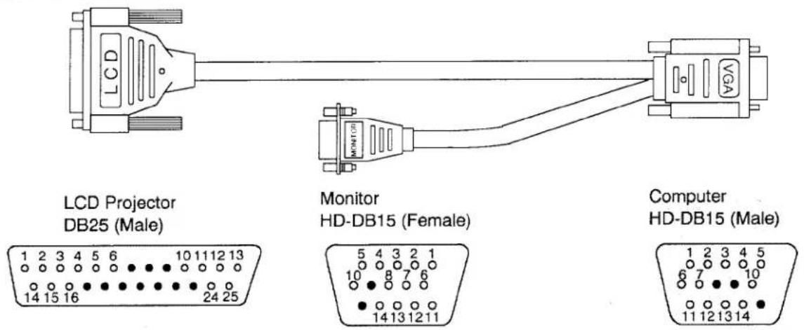
ACCESSORIES ADAPTER CABLE SPECIFICATIONS
(A) VGA Y CABLE
Pin No./Signal
1 R input
2 G input
3 B input
4 R output
5 G output
6 B output
7
8
9
10 Ground (H, V)
11 Ground (H, V)
12 V-sync.
13 H-sync.
14 R return
15 G return
16 B return
17
18
19
20
21
22
23
24 Ground
25 Ground
Pin No./Signal
1 R input
2 G input
3 B input
4 Sense 2
5 Not used
6 R Return
7 G Return
8 B Return
9
10 Ground (H,V)
11 Sense 0
12 Sense 1
13 H-sync.
14 V-sync.
15
Computer
HD-DB15 (Male)
Pin No./Signal
1 R output
2 G output
3 B output
4 Sense 2
5 Not used
6 Not used
7 Return (R, G, B)
8
9
10 Ground (H,V)
11 Sense 0
12 Sense 1
13 H-sync.
14 V-sync.
15
NOTE: Some computers scan the video output to see if a proper monitor is connected. In certain instances they will not provide an image to the projector if the monitor is not connected. In these circumstances, you will have to connect a monitor or a "monitor simulation" terminator plug into the monitor connector on the "Y" cable (the HD-DB15 shown above). The computer will then provide a proper image to the projector. A simulation terminator for the VGA monitor connector is included with the projector.
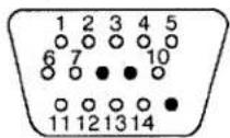
(B) MAC II Y CABLE
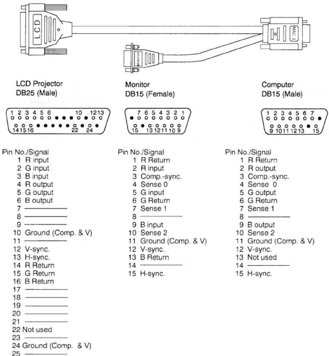
NOTE: Some Macintosh computers scan the video output to see if a proper monitor is connected. In certain instances they will not provide an image to the projector if the monitor is not connected. In these circumstances, you will have to connect a monitor or a "monitor simulation" terminator plug into the monitor connector on the "Y" cable (the DB15 shown above). The computer will then provide a proper image to the projector. A simulation terminator for the MAC monitor connector is included with the projector.
AV MODE (AV1 or AV2)
CONNECTING TO THE AV1 INPUT JACKS
Connect to the video and audio outputs of a VCR, video disc player, video camera, satellite TV tuner or other AV equipment.
- Connect video/audio outputs from external sources to these input jacks.
- If the audio signal from the AV equipment is stereo, be sure to connect the right and left channels to the respective right and left audio input jacks.
- If the external audio signal is monaural, connect it to the left jack.
- Do not connect the video sources to the AV1 (RCA) together with the BNC jack. Use one video input only for AV1.
S-VHS FORMAT VCR CONNECTION
The AV1 input includes an extra video input jack marked S-VIDEO to allow connection to an S-VHS format VCR that has separate Y/C video signals. The S-VIDEO jack has priority over the VIDEO (RCA or BNC) jack.
CONNECTING TO THE AV2 INPUT JACKS
Connect to the video and audio outputs of a VCR, video disc player, video camera, satellite TV tuner or other AV equipment.
- Connect video/audio outputs from external sources to these input jacks.
- If the audio signal from the AV equipment is stereo, be sure to connect the right and left channels to the respective right and left audio input jacks.
- If the external audio signal is monaural, connect it to the left jack.
CONNECTING TO THE MONITOR OUTPUT JACKS
These jacks will contain the audio/video information of the selected program source being viewed on the screen. If you have selected program source AV1 the audio signals connected to the AV1 jacks will be available at the monitor output jacks.
- Connect video/audio inputs from AV equipment to these output jacks.
- Whenever the S-VIDEO signal source is viewed on the screen, the video signal available at the MONITOR OUTPUT jack will be in black and white (monochrome).
■ When select "NORMAL" position by audio out function.
- If the audio input of the audio equipment is stereo, be sure to connect the right and left channels to the respective right and left jacks by RCA cable.
- If the audio input of the audio equipment is monaural, connect it to the left jack.
■ When select "600 Ω" position by audio out function.
- If the audio input of the audio equipment is 600 Ω balance (monaural), connect the projector and audio equipment as follows.
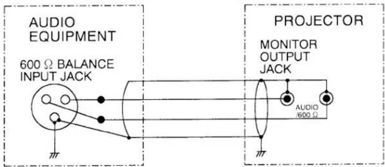
NOTE: This projector provides one line of the 600 Ω balance output only, cannot connect the external stereo audio equipment with 600 Ω balance input jack.
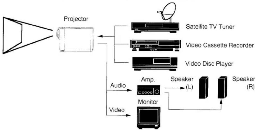
HOW TO CONNECT EXTERNAL AV EQUIPMENT
flowchart
graph TD
    A["Projector"] --> B["Satellite TV Tuner"]
    A --> C["Video Cassette Recorder"]
    A --> D["Video Disc Player"]
    B --> E["Audio"]
    C --> F["Monitor"]
    D --> G["Speaker (L)"]
    D --> H["Speaker (R)"]
    E --> I["Audio"]
    F --> J["Video"]
VIDEO EQUIPMENT

Satellite TV Tuner
flowchart
graph TD
    A["Audio INPUT"] --> B["Speaker (L)"]
    C["Audio OUTPUT"] --> D["Speaker (R)"]
    E["Audio Monitor OUTPUT"] --> F["Monitor"]
    G["Audio INPUT-1 or 2"] --> H["Audio INPUT"]
    I["Audio OUTPUT -1 or 2"] --> J["Audio INPUT"]
    K["Audio Monitor OUTPUT"] --> L["Monitor"]
    M["Audio INPUT"] --> N["Speaker (L)"]
    O["Audio OUTPUT"] --> P["Speaker (R)"]
    Q["Audio Monitor OUTPUT"] --> R["Monitor"]
    S["Audio INPUT"] --> T["Speaker (L)"]
    U["Audio OUTPUT"] --> V["Speaker (R)"]
    W["Audio Monitor OUTPUT"] --> X["Monitor"]
    Y["S-VHS VCR"] --> Z["Audio OUTPUT"]
    AA["S-VIDEO OUTPUT"] --> AB["Audio INPUT-1"]
    AC["S-VIDEO OUTPUT"] --> AD["Audio INPUT"]
SETTING-UP THE PROJECTOR
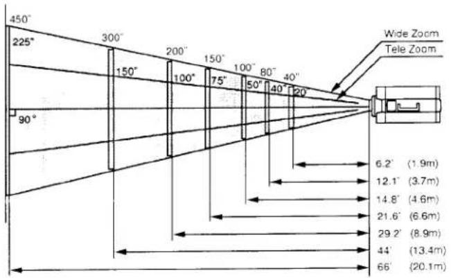
POSITIONING:
- This projector is basically designed to project on a flat projection surface.
- This projector can be focused from 3.2' (1.0m) \~ 53.8" (16.4m) (Model PLC-750M), 6.2' (1.9m) \~ 66' (20.1m) (Model PLC-755M).
- Use the illustration below as an example when positioning the projector to the screen.
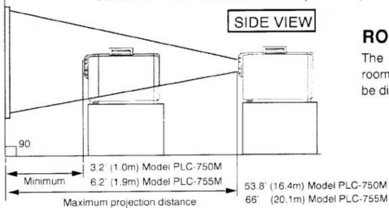
ROOM LIGHT
The projector should ideally be placed in a room with very limited light. Picture quality will be directly affected by lighting conditions.
TOP VIEW
DIAGONAL IMAGE SIZES
Model PLC-750M
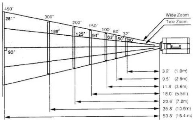
Model PLC-755M
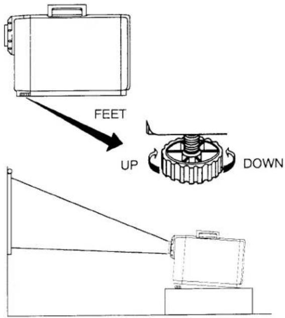
LEVELING AND ELEVATING ADJUSTMENTS
Picture adjustments can be made with the two leveling/elevating feet.
Adjustments of 5 up are possible by rotating the feet on the bottom of the projector.
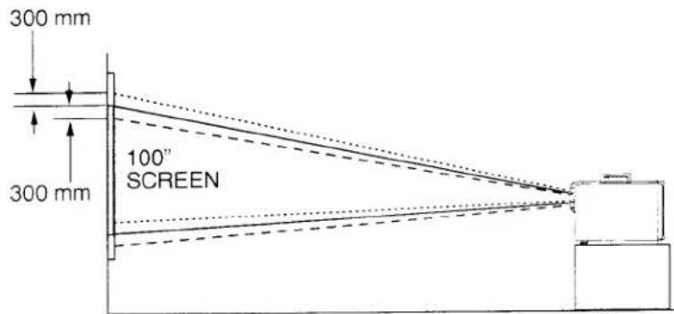
MOVE THE PROJECTED IMAGE POSITION
Adjust the projected image position ( maximum 300 mm downward or upward on the 100" screen) by using lens shift function (see other function setting on page 20.)
TOP CONTROLS
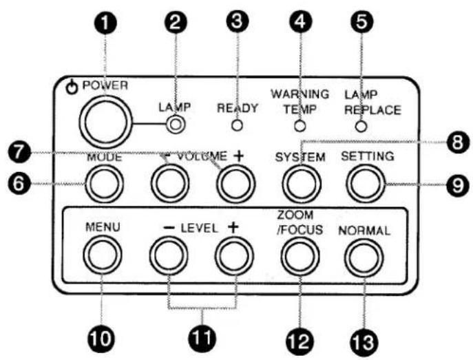
1 POWER (LAMP) ON/OFF BUTTON
Used to turn projection lamp on or off.
② POWER INDICATORS
Lights dim when the projector is on.
Lights bright when the projector is stand-by position.
3 READY INDICATORS
Lights green when projector lamp is ready to be turned on.
4 TEMPERATURE WARNING INDICATOR
Flashes red when internal projector temperature is too high.
⑤ LAMP REPLACEMENT INDICATOR
Lights orange when projection lamp is nearing end of service life.
6 MODE BUTTON
Used to select video source. (Computer Input, Video Input-1 or Video Input-2)
⑦ VOLUME BUTTONS
Used to adjust volume
8 SYSTEM BUTTON
● Computer Mode
Used to select computer system.
● AV Mode
Used to select color system.
⑨ SETTING BUTTON
Used to select on-screen adjustment displays for lens shift, display, blue background, reverse R/L and audio out.
Press repeatedly to cycle.
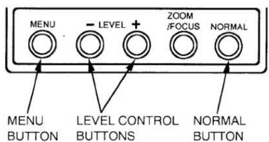
10 MENU BUTTON
● Computer Mode
Used to select on-screen adjustment displays for brightness, contrast, horizontal position, vertical position, fine sync and memory. Press repeatedly to cycle.
● AV Mode
Used to select on-screen adjustment displays for color, tint, brightness, contrast and sharpness. Press repeatedly to cycle.
11 LEVEL CONTROL BUTTONS
● Computer Mode
Used to adjust zoom, focus, brightness, contrast, horizontal position, vertical position, fine sync, memory, lens shift, display, blue background, reverse R/L and audio out by pressing + or - button.
● AV Mode
Used to adjust zoom, focus, color, tint, brightness, contrast, sharpness, lens shift, display, blue background, reverse R/L and audio out by pressing + or - button.
12 ZOOM/FOCUS BUTTON
Used to select power zoom lens or focus system.
13 NORMAL BUTTON
Used to reset to normal picture adjustment preset by factory.
BACK OF THE PROJECTOR
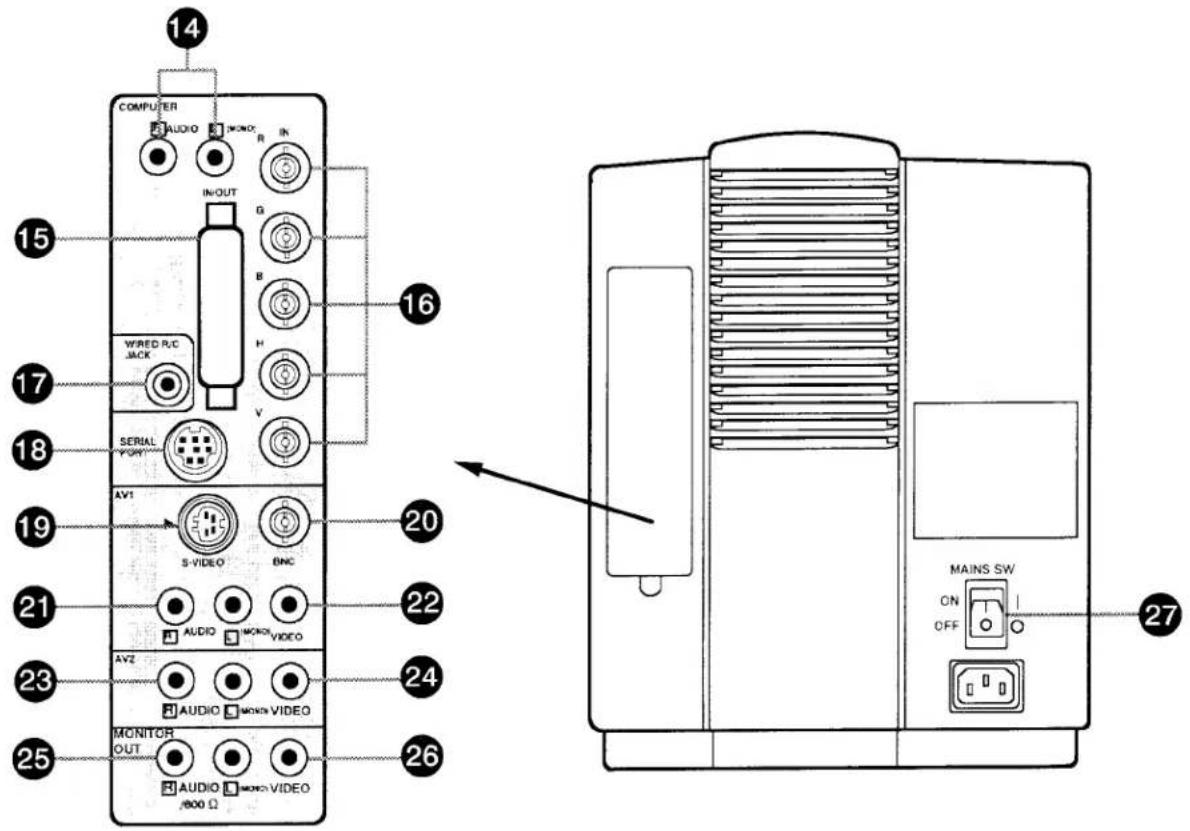
14 COMPUTER AUDIO INPUT JACKS
Used to connect a computer audio input to the projector.
15 COMPUTER INPUT/OUTPUT TERMINAL
Used to connect a computer to the projector.
16 COMPUTER INPUT JACKS (BNC) Red, Green, Blue, Horiz. Sync. and Vert. Sync.
Used to connect a computer to the projector.
17 WIRED REMOTE JACK
When using the wired remote control, connect the remote cable to this jack.
18 SERIAL PÖRT CONNECTOR
Used to connect a computer to the projector.
Used to connect a S-VHS video source to the projector.
20VIDEO INPUT-1 (BNC) JACK
Used to connect a video source to the projector.
21 AUDIO INPUT-1 JACKS
Used to connect an audio input to the projector.
22 VIDEO INPUT-1 JACK
Used to connect a video source to the projector.
23 AUDIO INPUT-2 JACKS
Used to connect an audio input to the projector.
Used to connect a video source to the projector.
25 AUDIO MONITOR OUTPUT JACKS
Permits audio connection to a monitor.
26 VIDEO MONITOR OUTPUT JACK
Permits video connection to a monitor.
27 MAINS ON/OFF SWITCH
Used to turn the projector on.
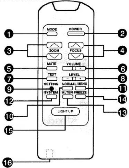
Used to turn projection lamp on or off.
③ ZOOM BUTTONS
Used to operate power zoom lens.
4 FOCUS BUTTONS
Used to operate power focus system.
5 SOUND MUTE BUTTON
Used to mute sound.
6 VOLUME BUTTONS
Used to adjust volume.
⑦ TEXT BUTTON (Computer mode only)
Used to select VGA TEXT (VGA 720 × 400) mode or VGA GRAPHIC (VGA 640 × 400) mode.
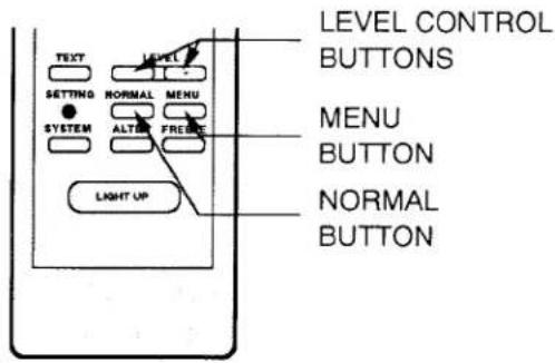
8 LEVEL CONTROL BUTTONS
● Computer Mode
Used to adjust brightness, contrast, horizontal position, vertical position, fine sync, memory, lens shift, display, blue background, reverse R/L and audio out by pressing + or - button.
● AV Mode
Used to adjust color, tint, brightness, contrast, sharpness, lens shift, display, blue background, reverse R/L and audio out by pressing + or - button.
9 SETTING BUTTON
Used to select on-screen adjustment displays for lens shift, display, blue background, reverse R/L and audio out.
10 NORMAL BUTTON
Used to reset to normal picture adjustment preset by factory.
11 MENU BUTTON
● Computer Mode
Used to select on-screen adjustment displays for brightness, contrast, horizontal position, vertical position, fine sync and memory. Press repeatedly to cycle.
● AV Mode
Used to select on-screen adjustment displays for color, tint, brightness, contrast and sharpness. Press repeatedly to cycle.
12 SYSTEM SELECT BUTTON
● Computer Mode
Used to select computer system.
● AV Mode
Used to select color system.
13 ALTER BUTTON
Used to select previous video mode.
14 FREEZE BUTTON
Use this button to hold a still picture on-screen.
15 LIGHT UP BUTTON
Press to light the back light for function buttons on the remote control unit for 5 seconds. Press any other function button during the lighting to light for another 5 seconds.
16 WIRED REMOTE JACK
When using the wired remote control, connect the remote cable to this jack.
INFRARED/WIRED REMOTE CONTROL
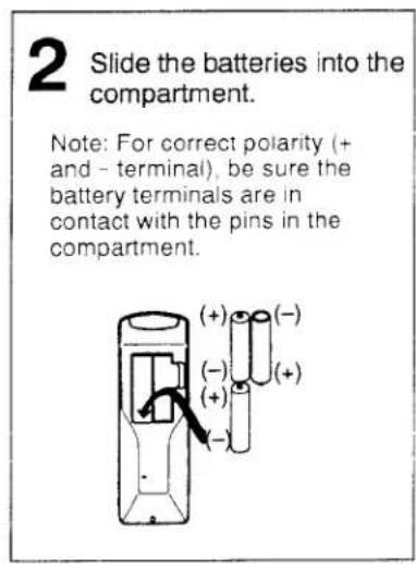
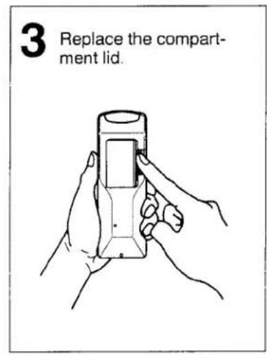
REMOTE CONTROL BATTERY INSTALLATION
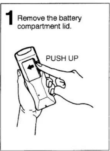
The remote control unit can be used as wireless or wired remote control.
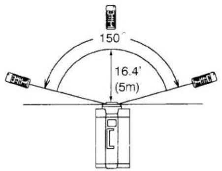
USING THE REMOTE CONTROL UNIT (wireless)
Point the remote control toward the front of the projector (Receiver window) whenever pressing the buttons. Maximum operating range for the remote control is about 16.4' (5m) and 150° from the front of the projector.
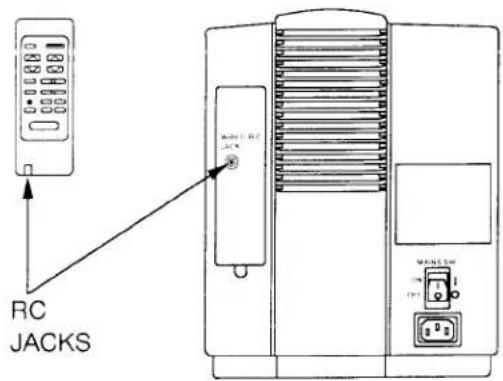
USING THE REMOTE CONTROL UNIT (wired)
Connect a remote control cable to RC jacks located on the remote control unit and the back of the projector.
To insure safe operation, please observe the following precautions:
* Use (3) AA type batteries.
* Change three batteries at the same time.
* Do not use a new battery with a used battery.
* Avoid contact with water.
* Do not drop the remote control unit.
USING THE PROJECTOR
TO TURN ON THE PROJECTOR
Connect the projector to a video source (Computer, VCR, Video Camera, Video Disc Player, etc.) using the appropriate terminals on the rear of the projector (See page 6-11).
Connect the projector's AC power cord into a wall outlet and turn the MAINS ON/OFF switch (located on the back of the projector) to ON position. The POWER indicator will light RED and the READY indicator will light GREEN.
Press the POWER (LAMP) ON/OFF button on the projector or on the remote control unit to ON. The POWER indicator will light dim and the cooling fan will operate. The wait display (A MOMENT!/UN MOMENTO! and numeral 30) appears on the screen and the count-down starts (30-29-28-...1). The signal from the video source appears after 30 seconds.
A MOMENT!/UN MOMENTO!

CAUTION:
- THIS PROJECTOR USES A METAL-HALIDE ARC LAMP. IF YOU TURN ON THE LAMP, DO NOT TURN IT OFF FOR AT LEAST 5 MINUTES SO THAT ITS LIFE WILL NOT GET SHORTER.
- DO NOT UNPLUG THE PROJECTOR OR TURN THE MAINS ON/OFF SWITCH (LOCATED ON THE BACK OF THE PROJECTOR) TO OFF UNTIL THE COOLING FAN HAS STOPPED OPERATING.
NOTE 1: After you turn off the projector using the POWER (LAMP) ON/OFF button on the projector (or on the remote control unit) you must wait one minute before you can turn the projector on again.
NOTE 2: TEMPERATURE WARNING INDICATOR flashes red, the projector will automatically turn off. Wait at least 5 minutes before turning the projector on.
If the TEMPERATURE WARNING INDICATOR continues to flash, follow the procedures below:
(1). Press POWER (LAMP) ON/OFF button to OFF.
(2). Check the air filter for dust accumulation.
(3). Remove dust with vacuum cleaner (See air filter care and cleaning on page 23.)
(4). Press POWER (LAMP) ON/OFF button to ON.
If the TEMPERATURE WARNING INDICATOR still continues to flash, call your authorized distributor or dealer for service.
TO TURN OFF THE PROJECTOR
Press the POWER (LAMP) ON/OFF button on the projector or on the remote control unit. The "☐" POWER OFF ?" appears on the screen. Press again the POWER (LAMP) ON/OFF button to OFF the projector. The POWER indicator will light bright and READY indicator will turn off. The cooling fan will operate for 1 minute after the projector is turned off. (During this "cooling down" period, the projector can not be turned on.)
After 1 minute, the READY indicator will light green again and the projector may be turned on by pressing the POWER (LAMP) ON/OFF button.

POWER OFF?
ADJUST THE PROJECTOR
VIDEO MODE SELECT
Press the MODE button (located on projector or remote control unit) to select Computer Input, Video Input-1 or Video Input-2. The "COMPUTER", "AV1" or "AV2" display will appear on the screen.
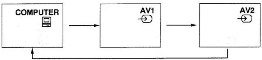
flowchart
graph LR
    A["COMPUTER"] --> B["AV1"]
    B --> C["AV2"]
    C --> A
Press the ALTER button on the remote control unit to alternate quickly between the two modes. (Current mode and Previous mode)
For example, Computer IN/OUT Terminals and AV1 are connected with personal computer and VCR respectively. Firstly project computer image on the screen. Secondly press MODE button to select AV1. And then, press ALTER button to select previous mode (Computer mode).
| CURRENT MODE | PREVIOUS MODE |
| AV1 MODE | COMPUTER MODE |
| COMPUTER MODE | AV2 MODE |
| AV2 MODE | AV1 MODE |
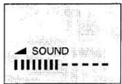
VOLUME ADJUSTMENT
Press VOLUME buttons (located on projector or remote control unit) to adjust the volume. The screen display will appear.
Pressing (+) will increase volume and the green indicator will increase to the right on the screen.
Pressing (−) will decrease volume and the green indicator will decrease to the left on the screen.
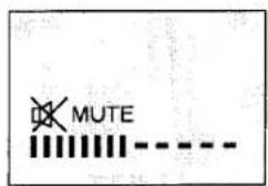
SOUND MUTE ADJUSTMENT
Pressing SOUND MUTE button on the remote control unit will mute audio. Press SOUND MUTE button again to restore audio to its previous level.
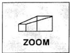
ZOOM ADJUSTMENT (Without remote control unit)
Press ZOOM/FOCUS button until zoom display appears on the screen, and press LEVEL (+) or (−) to obtain your desired picture size. (The zoom display will appear for 5 seconds.) For a larger picture, press (+) and for a smaller picture, press (−).
ZOOM ADJUSTMENT (With remote control unit)
Press ZOOM ( ) or ( ) to obtain your desired picture size. (The zoom display will appear for 5 seconds.) For a larger picture, press ( ) and for a smaller picture, press ( ).
FOCUS ADJUSTMENT (Without remote control unit)
Press ZOOM/FOCUS button until focus display appears on the screen, and press LEVEL (+) or (−) for sharper, crisper picture. (The focus display will appear for 5 seconds.)
FOCUS ADJUSTMENT (With remote control unit)
Press FOCUS ( ) or ( ) for sharper, crisper picture. (The focus display will appear for 5 seconds.)
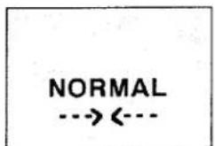
PICTURE ADJUSTMENT
The normal picture level is factory preset on the projector and can be obtained anytime by pressing the NORMAL button on the projector, or on the remote control unit. (The Normal display will appear for 5 seconds.)
Picture adjustments can be made by using the MENU and LEVEL buttons on the projector, or on the remote control unit. (See picture adjustment on page 21-22.)

SYSTEM SELECT
• COMPUTER MODE
When a computer is connected to the projector and both of the computer and the projector are turned On, the type of the connected computer system appears on the screen. (See "ON-SCREEN DISPLAY" on page 27.)
If any of the following 5 computer systems is connected to the projector and the projector cannot discriminate those systems, press the "SYSTEM" button to select the correct system of the connected computer.
- "MAC II NORMAL" and "MAC LC 13RGB"
- "CGA TEXT" and "CGA GRAPHIC"
- "APPLE II e" and "FMT 320×200
- "VGA 640*400" and "VGA 720*400"
- "VGA 640*480" and "GENOA"
For example; The display of "MAC II NORMAL" will appear on-screen when the signal comes from Mac II normal, Super Mac and/or Raster Ops.
In case of connecting Mac LC 13" RGB monitor, press SYSTEM button (located on projector or remote control unit) to select the display of "MAC LC 13RGB".

flowchart
graph LR
    A["MAC II NORMAL"] <--> B["MAC LC 13RGB"]
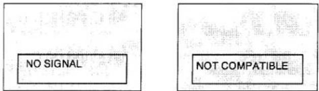
NOTE:
- If no input signal from the computer, the "NO SIGNAL" display appears on the screen.
- If the projector cannot discriminate the input signal from the computer, the "NOT COMPATIBLE" display appears on the screen.
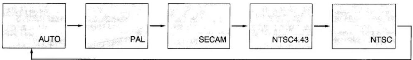
- AV MODE
Press the SYSTEM button (located on projector or remote control unit) to select AUTO, PAL, SECAM, NTSC4.43 or NTSC.
Each time the SYSTEM button is pressed, the color system changes as follows:
When the color system is set to "AUTO" position, this projector can receive color programs from one of the 4 systems (PAL, SECAM, NTSC4.43 or NTSC), automatically.
If the picture quality is poor, make sure the proper color system is selected to match the video source.
flowchart
graph LR
    A["AUTO"] --> B["PAL"]
    B --> C["SECAM"]
    C --> D["NTSC4.43"]
    D --> E["NTSC"]
    E --> F["Feedback Loop"]
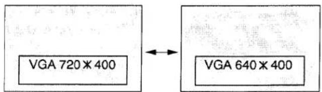
TEXT SELECT
(VGA 720 × 400 and VGA 640 × 400 used only)
Press the TEXT button on the remote control unit to select "VGA 720*400"-TEXT- or "VGA 640*400"-GRAPHIC-.
NOTE: "720×400" TEXT mode is projected to be compressed as "640 × 400".
FREEZE FUNCTION
Press the FREEZE button on the remote control unit, and then, the still picture will remain on-screen. This function is cancelled when the FREEZE button is pressed again or any other function button is pressed.
NOTE: Your computer is not affected by this function, and will continue to run.
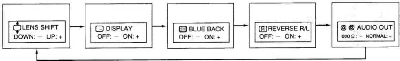
OTHER FUNCTION SETTING
This projector has other function settings; lens shift, display, blue background, reverse R/L and audio out. These setting by using SETTING and LEVEL buttons on the projector or remote control unit.
- Press SETTING button to select the function.
Each time the SETTING button is pressed, the control function changes as follows:
flowchart
graph LR
    A["LENS SHIFT DOWN: - UP: +"] --> B["DISPLAY OFF: - ON: +"]
    B --> C["BLUE BACK OFF: - ON: +"]
    C --> D["REVERSE R/L OFF: - ON: +"]
    D --> E["AUDIO OUT 600 Ω: - NORMAL: +"]
    E --> A
- Adjust the lens shift, display, blue background, reverse R/L and audio out by pressing LEVEL (- and +) buttons.
- The ON-SCREEN display will disappear automatically in 5 seconds.
LENS SHIFT
Press SETTING button (located on the projector or remote control unit) to select the lens shift function. Then press LEVEL buttons (located on the projector or remote control unit) to adjust the lens position.
Pressing (+) will shift up the lens.
Pressing (−) will shift down the lens.
The projected image position can be adjusted (maximum 300 mm, downward or upward on the 100" screen) by using this function.
DISPLAY
When this function is "ON" position, the projector to see the on-screen display of all setting and adjustment will be appeared.
When this function is "OFF" position, the projector to see the on-screen display of any setting and adjustment (related of Picture Adjustment and Other Function Setting) will be appeared.
BLUE BACK
When this function is in the "ON" position, the projector will project the blue image without video noise on the screen when the video source is unplugged or turned off.
PICTURE SCAN
When this function is in the "ON" position, versatile left/right picture reverse capability lets you project onto a rear projection screen.
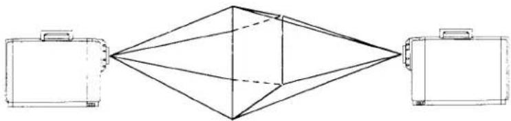
natural_image
Diagram showing three briefcases connected to a central geometric structure (no text or symbols)AUDIO OUT
When this function is in the "600 Ω" position, the audio monitor output is changed 600 Ω impedance balance output.
Connect the projector and external audio equipment with 600 Ω balance input jack, select the "600 Ω" position by this function.
PICTURE ADJUSTMENTS
TOP CONTROLS
REMOTE CONTROL UNIT
(A) COMPUTER MODE
Picture adjustments have been preset at the factory to our quality standards. The picture adjustments can be made by the MENU and LEVEL buttons on the projector or on the remote control unit.
- Press the MENU button to select the picture adjustments function.
Each time the MENU button is pressed, the control function changes as follows:
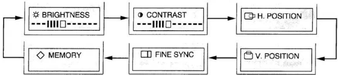
flowchart
graph TD
    A["BRIGHTNESS"] --> B["CONTRAST"]
    B --> C["H. POSITION"]
    D["MEMORY"] --> E["FINE SYNC"]
    E --> F["V. POSITION"]
    C --> F
    F --> A
-
Adjust the brightness, contrast, H. position, V. position or fine sync by pressing the LEVEL (+ and -) buttons.
-
The ON-SCREEN display will disappear automatically in 5 seconds.
| - LEVEL +← - - ■ - - →• Press the LEVEL CONTROL buttons to make adjustments.Refer to the control chart below. | |
| BRIGHTNESS | DARKER ←→ BRIGHTER |
| CONTRAST | SOFTER ←→ SHARPER |
| H. POSITION | LEFT ←→ RIGHT |
| V. POSITION | DOWNWARD ←→ UPWARD |
| FINE SYNC | Press the LEVEL CONTROL buttons ( - or +) as necessary to eliminate flicker from the display. |
NOTE: The projector may not reproduce a proper image for SVGA signal. Because SVGA (800 × 600) image is converted to VGA (640 × 480) image by partial scan, some lines and dots of the image do not appear. The flicker on this compressed SVGA image cannot be eliminated even though you try to make a FINE SYNC adjustment.
- Then press the MENU button to select the MEMORY menu. Press the LEVEL + button to save the picture adjustment levels in memory.
NOTE: The projector is equipped with a built-in memory feature that can maintain the picture adjustment levels if the projector is turned off and AC power cord is disconnected. If NORMAL button is pressed, the projector will return to factory preset level.
(B) AV1 and AV2 MODE
Picture adjustments have been preset at the factory to our quality standards. The picture adjustments can be made by the MENU and LEVEL buttons on the projector or on the remote control unit.
- Press the MENU button to select the picture adjustments function.
Each time the MENU button is pressed, the control function changes as follows:
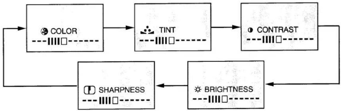
flowchart
graph TD
    A["COLOR"] --> B["TINT"]
    B --> C["CONTRAST"]
    C --> D["BRIGHTNESS"]
    D --> E["SHARPNESS"]
    E --> A
NOTE: 1. "TINT" will be skipped during in the PAL and SECAM mode.
- Adjust the color intensity, tint, contrast, brightness or sharpness by pressing the LEVEL (+ and -) buttons.
- The ON-SCREEN display will disappear automatically in 5 seconds.
| - LEVEL +← - - ■ - - → | |
| • Press the LEVEL CONTROL buttons to make adjustments.Refer to the control chart below. | |
| COLOR | DECREASES ←→ INCREASES |
| TINT | MORE GREEN ←→ MORE PURPLE |
| CONTRAST | SOFTER ←→ SHARPER |
| BRIGHTNESS | DARKER ←→ BRIGHTER |
| SHARPNESS | SOFTER ←→ SHARPER |
NOTE: The projector is equipped with a built-in memory feature that can maintain the picture adjustment levels set on AV1 and AV2 respectively even if the projector is turned off and AC power cord is disconnected. If the NORMAL button is pressed, the projector will return to factory preset level.
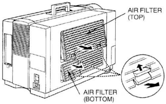
AIR FILTER CARE AND CLEANING
The removable air filter prevents dust from accumulating on the surface of the projection lens and projection mirror. Should the air filter become clogged with dust particles, it will reduce the cooling fan's effectiveness and may result in internal heat built up and reduce the life of the projection lamp.
AIR FILTER (TOP)
When the air filter is blackened, it is time to change new air filter. Request service from an authorized dealer or service station.
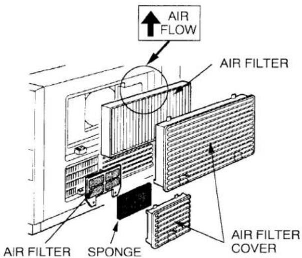
Be sure to face the air filter in the correct direction when installing inside of the filter cover. Attach the air filter with the arrow on the "AIR FLOW" label facing towards the inside of the projector.
To change the air filter, follow the procedures below:
- Turn the POWER (LAMP) ON/OFF button OFF.
- Remove the air filter cover from the side of the projector.
- Remove the air filter from the filter cover.
- Replace the air filter. Make sure that air filter cover is fully inserted.
AIR FILTER (BOTTOM)
To clean the air filter, follow the cleaning procedures below:
- Turn the POWER (LAMP) ON/OFF button OFF.
- Remove the air filter cover from the side of the projector.
- Remove the air filter and sponge from the filter cover.
- Clean the air filter and sponge with a vacuum cleaner.
- Replace the air filter and sponge. Make sure that air filter cover is fully inserted.

Do not clean with water. Doing so may damage the air filter.
Do not operate the projector with air filter removed.
RECOMMENDATION
TO ENJOY PICTURE IMAGE, USE THE PROJECTOR IN THE CLEAN ENVIRONMENT. USAGE IN THE CLEAN ENVIRONMENT IS RECOMMENDED.
When used under the dusty or smoky conditions, dust may accumulate on the liquid crystal panel and lens inside it, and may resultantly be projected on the screen together with the picture.
When the above symptoms are noticed contact the place where your purchased or the nearest service center for the cleaning.
LAMP REPLACEMENT & TEMPERATURE WARNING INDICATORS
LAMP REPLACEMENT INDICATOR
When the lamp nears the end of its service life, the picture quality and color quality will deteriorate and the lamp replacement indicator will light orange.

DO NOT ATTEMPT TO REMOVE OR CHANGE THE PROJECTION LAMP. THE LAMP CAN ONLY BE CHANGED BY QUALIFIED SERVICE PERSONNEL.
TEMPERATURE WARNING INDICATOR
The TEMPERATURE WARNING INDICATOR flashes red when the internal temperature of the projector exceeds the normal temperature.
Possible causes for the temperature warning may be:
-
Ventilation slots at the side of the projector are blocked. In such an event, reposition the projector so that ventilation slots are not obstructed.
-
Air filter is clogged with dust particles. Remove dust from the air filter by following instructions in the Air Filter Care and Cleaning section above.
If temperature warning indicator remains on after performing the checks listed above, cooling fan/internal circuits may be malfunctioning. Request service from an authorized dealer or service station.
HELPFUL HINTS-Problems and Solutions
Check the following chart before requesting service.
| Problem: | Try these Solutions: |
| No power | Plug the projector into an AC outlet.Turn the MAINS ON/OFF switch to ON.Press the POWER (LAMP) ON/OFF button to ON.Check the READY INDICATOR light ON.One minute has not passed after the projector turned OFF.NOTE: After pressing the POWER (LAMP) ON/OFF button to OFF, the projector functions as follows.The POWER and READY indicator will turn off.The cooling fan will operate for 1 minute after the projector is turned off. (During this "cooling down period, the projector can not be turned on.)After 1 minute, the READY indicator will light green again and the projector may be turned on by pressing the POWER (LAMP)ON/OFF button. |
| No sound from built-in speaker | Press the VOLUME (▲) and (▼) to (▲).Check audio cable connection from audio input source. |
| No color | Check color system. |
| Picture is reversed | Check REVERSE R/L Feature. |
| Picture blurred or color faded | Check the projection distance.Adjust the FOCUS control.NOTE: Moving the projector from a cool temperature location to a warm temperature location may result in moisture condensation on the lens. In such an event, leave the projector OFF and wait until condensation disappears. |
SERVICE
WARNING: High voltages are used to operate this projector. Do not remove the back from your unit.
You can often correct operating problems yourself. If the projector fails to work properly, locate the operating problem in the Helpful Hints Chart. To correct them, try the "Solutions."
Sanyo Service is easily obtained. If after following all operating instructions, you find that service is necessary, contact the SFS Corporation in Los Angeles, or the store where you purchased the unit. Give the model number and explain the difficulty. We will advise you how to obtain service.
TECHNICAL SPECIFICATIONS
SPECIFICATIONS
| Projector Type | LC Data-Grade Projector |
| Dimensions (W x H x D) | 13.3" (337.5 mm) × 15.5" (394 mm) × 22" (594 mm) |
| Net Weight | 53.9 lbs (23.5 kg) |
| LCD Panel System | 3.1" TFT Active Matrix type (Thin Film Transistor) × 3 |
| Number of Pixels | 921,600 (307,200 × 3) |
| Color System | 4 color system (PAL, SECAM, NTSC4.43 and NTSC) |
| Projection Image Size (Diagonal) | Adjustable from 20" to 450" |
| Contrast Ratio | 100 :1 |
| Horizontal Resolution | 550 TV lines |
| Projection Lens (Model PLC-750M) | F3.8~ 4.8, f4.57"~7.28" with Motor zoom and focus |
| Projection Lens (Model PLC-755M) | F4.2~ 4.5, f 5.31"~10.63" with Motor zoom and focus |
| Motorized Lens Shift | ± 300 mm on 100" screen |
| Lens Aperture (Model PLC-750M) | 2.44" (62 mm) |
| Lens Aperture (Model PLC-755M) | 2.64" (67 mm) |
| Throw Distance (Model PLC-750M) | 3.2' (1.0 m) ~ 53.8' (16.4m) |
| Throw Distance (Model PLC-755M) | 6.2' (1.9 m) ~ 66' (20.1m) |
| Projection Lamp | Metal Halide, 400 watt |
| Projection Mirror | Dichroic mirror system |
| AV Input jacks | RCA Type × 6 (2 Set Video, Audio R and L), BNC Type × 1 DIN 4 pin (S-Video) × 1 |
| Computer Input/Output Jack | DB25 Terminal × 1, DIN 8 Pin (SERIAL PORT) × 1 BNC Type × 5 (Red, Green, Blue, Horiz. Sync. and Vert. Sync.) |
| Computer Audio Input Jack | RCA Type × 2 (R and L) |
| Video Monitor Output Jack | RCA Type × 1 |
| Audio Monitor Output Jacks | RCA Type × 2 (R and L) |
| Built-in Speaker | INT. SP. Monaural, 3 watt RMS (T.H.D. 10%) |
| Image Elevation Adjustment | Up 5° |
| Voltage | 100 ~ 120V, 200 ~ 240V AC, 50/60 Hz |
| Power Consumption | 630 Watts, 6.5/3.0 A (Max. Ampere) |
| Operating Temperature | 5°C ~ 35°C |
| Storage Temperature | -10°C ~ 60°C |
| Remote Control Battery | (3) AA Type |
| Standard Accessories | Remote Control Unit, R/C Cable 5' (1.5m), Software Kit, AC Power Supply Cord, VGA Y Cable, MAC II Y Cable, Lens Cover, VGA Video Terminator, Macintosh Video Terminator, Owner's Instruction Manual and Protective Dust Cover |
COMPATIBLE PERSONAL COMPUTER SPECIFICATIONS
| ON-SCREEN DISPLAY | COMPATIBLE COMPUTER | DOT × LINES | fH (kHz) | 1V (LINE) | POLA. | |
| H | V | |||||
| SVGA1 | SVGA 800 × 600 | 800 × 600 | 37.97 | 628 | - | - |
| SVGA2 | SVGA 800 × 600 | 800 × 600 | 36.54 | 628 | - | - |
| SVGA3 | SVGA 800 × 600 | 800 × 600 | 35.25 | 624 | + | + |
| APPLE II e | APPLE II e | 560 × 192 | 15.70 | 262 | - | - |
| FMT 320 × 200 | FM-TOWNS (L) | 320 × 240 | 15.73 | 262 | - | - |
| CGA TEXT | CGA TEXT | 640 × 200 | 15.70 | 262 | + | + |
| CGA GRAPHIC | CGA GRAPHIC | 640 × 200 | 15.70 | 262 | + | + |
| HGC TEXT | HGC TEXT | 720 × 350 | 18.14 | 370 | + | - |
| HGC GRAPHIC | HGC GRAPHIC | 720 × 348 | 18.52 | 370 | + | - |
| EGA TEXT | EGA TEXT | 640 × 350 | 21.63 | 366 | + | - |
| EGA GRAPHIC | EGA GRAPHIC | 640 × 350 | 21.85 | 366 | + | - |
| MAC SE | MAC SE | 512 × 342 | 22.25 | 370 | + | + |
| FMT 640 × 400 | FM-TOWNS (640 × 400) | 640 × 400 | 24.37 | 440 | - | - |
| MAC LC 12 | MAC LC (12" MONITOR) | 512 × 384 | 24.48 | 407 | - | - |
| PC98 640 × 400 | PC-9801 (640 × 400) | 640 × 400 | 24.83 | 440 | - | - |
| PC-9821 (640 × 400) | 640 × 400 | 24.83 | 440 | - | - | |
| AT&T | AT&T6300 (350 LINE) | 640 × 350 | 25.86 | 432 | + | + |
| AT&T6300 (400 LINE) | 640 × 400 | 25.86 | 432 | + | + | |
| AX286/386 | AX-286/386 | 640 × 480 | 30.27 | 501 | + | - |
| VGA 640 × 400 | VGA 640 × 400 | 640 × 400 | 31.47 | 449 | - | + |
| VGA 720 × 400 | VGA 720 × 400 | 720 × 400 | 31.47 | 449 | - | + |
| VGA 640 × 350 | VGA 640 × 350 | 640 × 350 | 31.47 | 449 | + | - |
| VGA 640 × 480 | VGA 640 × 480 | 640 × 480 | 31.47 | 525 | - | - |
| PC-9821 (640 × 480) | 640 × 480 | 31.47 | 525 | - | - | |
| FM-TOWNS (640 × 480) | 640 × 480 | 31.47 | 525 | - | - | |
| MBC-P100J | 640 × 480 | 31.47 | 525 | - | - | |
| J-3100VS | 640 × 480 | 31.47 | 525 | - | - | |
| T-4500C | 640 × 480 | 31.32 | 525 | - | - | |
| GENOA | GENOA 6000 (60 Hz) | 640 × 480 | 31.47 | 525 | - | - |
| VGA 640 × 400 525 LINE | VGA 640 × 400 525 LINE | 640 × 400 | 31.47 | 525 | - | + |
| VGA 640 × 350 525 LINE | VGA 640 × 350 525 LINE | 640 × 350 | 31.47 | 525 | + | - |
| MAC II NORMAL | MAC II (NORMAL) | 640 × 480 | 35.00 | 525 | - | + |
| MAC II (SuperMac) | 640 × 480 | 35.00 | 525 | - | + | |
| MAC II (RasterOps) | 640 × 480 | 35.00 | 525 | - | + | |
| MAC LC 13RGB | MAC LC (13"RGB-MO) | 640 × 480 | 34.97 | 525 | - | - |
| VESA | VESA VS901001 | 640 × 480 | 37.86 | 520 | - | - |
| GENOA | GENOA 6000 (70 Hz) | 640 × 480 | 37.90 | 509 | - | + |
NOTE: 1. The projector may not reproduce a proper image for SVGA signal. Because SVGA (800 × 600) image is converted to VGA (640 × 480) image by partial scan, some lines and dots of the image do not appear.
- Specifications are subject to change without notice.
SANYO INDUSTRIAL VIDEO LCD PROJECTOR LIMITED WARRANTY
OBLIGATIONS
In order to obtain warranty service, the product must be delivered to and picked up from an Authorized Sanyo Service Center at the user's expense, unless specifically stated otherwise in this warranty. The names and addresses of Authorized Sanyo Service Centers may be obtained by writing to SFS Corporation, SFC's warranty administrator, at any of the addresses listed below, or by calling (toll-free) 1-800-421-5013.
New Jersey Office
210 Riser Road
Little Ferry, NJ 07643
201-641-3000
California Office
1200 W. Artesia Blvd.
Compton, CA 90220
310-537-5830
Illinois Office
900 N. Arlington Heights Road
Itasca, IL 60143 U.S.A.
708-775-1414
THIS WARRANTY IS VALID ONLY ON SANYO PRODUCTS PURCHASED OR RENTED IN THE UNITED STATES OF AMERICA, EXCLUDING HAWAII AND ALL U.S. TERRITORIES AND PROTECTORATES. THIS WARRANTY APPLIES ONLY TO THE ORIGINAL RETAIL USER. THE ORIGINAL DATED BILL OF SALE, SALES SLIP OR RENTAL AGREEMENT MUST BE SUBMITTED TO THE AUTHORIZED SANYO SERVICE CENTER AT THE TIME WARRANTY SERVICE IS REQUESTED.
Subject to the OBLIGATIONS above and EXCLUSIONS below, SANYO FISHER (USA) CORPORATION (SFC) warrants this SANYO product against defects in materials and workmanship for the periods specified below. SFC will repair or replace (at its option) the product and any of its parts which fail to conform to this warranty. The warranty period commences on the date the product was first purchased or rented at retail.
| LABOR | PARTS | LAMP |
| 1 YEAR | 1 YEAR | 90 DAYS |
EXCLUSIONS
This warranty does not cover (A) the adjustment of customer-operated controls as explained in the appropriate model's instruction manual, or (B) the repair of any product whose serial number has been altered, defaced or removed.
This warranty shall not apply to the cabinet or cosmetic parts, knobs or batteries.
This warranty does not apply to uncrating, setup, installation, removal of the product for repair or reinstallation of the product after repair.
This warranty does not apply to repairs or replacements necessitated by any cause beyond the control of SFC including, but not limited to, any malfunction, defect or failure caused by or resulting from unauthorized service or parts, improper maintenance, operation contrary to furnished instructions, shipping or transit accidents, modification or repair by the user, abuse, misuse, neglect, accident, incorrect power line voltage, fire, flood or other Acts of God, or normal wear and tear.
The foregoing is in lieu of all other expressed warranties and SFC does not assume or authorize any party to assume for it any other obligation or liability.
THE DURATION OF ANY WARRANTIES WHICH MAY BE IMPLIED BY LAW (INCLUDING THE WARRANTIES OF MERCHANTABILITY AND FITNESS) IS LIMITED TO THE TERM OF THIS WARRANTY. IN NO EVENT SHALL SFC BE LIABLE FOR SPECIAL, INCIDENTAL OR CONSEQUENTIAL DAMAGES ARISING FROM OWNERSHIP OR USE OF THIS PRODUCT, OR FOR ANY DELAY IN THE PERFORMANCE OF ITS OBLIGATIONS UNDER THIS WARRANTY DUE TO CAUSES BEYOND ITS CONTROL.
SOME STATES DO NOT ALLOW LIMITATIONS ON HOW LONG AN IMPLIED WARRANTY LASTS AND/OR DO NOT ALLOW THE EXCLUSION OR LIMITATION OF CONSEQUENTIAL DAMAGES, SO THE ABOVE LIMITATIONS AND EXCLUSIONS MAY NOT APPLY TO YOU.
THIS WARRANTY GIVES YOU SPECIFIC LEGAL RIGHTS. YOU MAY HAVE OTHER RIGHTS, WHICH VARY FROM STATE TO STATE.
ATTENTION
For your protection in the event of theft or loss of this product, please fill in the information below for your own personal records.
Model No.
Serial No.
(Located on back or bottom side of unit.)
Date of Purchase
Purchase Price
Where Purchased
Part No. 610 264 4418 (1AA6P1P1054-- M6HA)

21350 Lassen Street
Chatsworth, California 91311
Printed in Japan