
PLC-EF10N - Projector SANYO - Free user manual and instructions
Find the device manual for free PLC-EF10N SANYO in PDF.


| Product Type | Multimedia Video Projector |
| Model | PLC-EF10N |
| Brand | Sanyo |
| Display Technology | 3 x 1.8" TFT Active Matrix LCD |
| Native Resolution | 1280 x 1024 (SXGA) |
| Maximum Input Resolution | 1600 x 1200 (UXGA) |
| Number of Pixels | 3,932,160 (1,310,720 x 3) |
| Color Palette | 16.77 million colors |
| Projection Lens | F2.0 – F2.3, f=75.7 – 97.5 mm, motorized zoom and focus |
| Lens Shift | Motorized, ±760 mm on 100" screen (vertical) |
| Projection Lamp | 400 W |
| Projection Image Size | 40" to 600" diagonal |
| Throw Distance | 4.9 ft (1.5 m) to 80.7 ft (24.6 m) |
| Horizontal Resolution | 800 TV lines |
| Color Systems | PAL, SECAM, NTSC, NTSC4.43, PAL-M, PAL-N |
| Scanning Frequency | H: 15–100 kHz, V: 50–100 Hz |
| Computer Input 1 | Analog HDB15-pin, Digital MDR20-pin |
| Computer Input 2 | 5 x BNC (R,G,B,H,V) |
| Video Inputs | 2 x 3 BNC (Composite/Y/C/Component), 2 x S-Video (DIN4) |
| Audio Inputs | 2 x RCA stereo (L/R) for computer, 2 x RCA stereo (L/R) for video |
| Built-in Speaker | 3W + 3W stereo (RMS) |
| Control Ports | 2 x Multipole 12-pin, 2 x USB, 1 x Serial DB9 |
| Wired Remote Jack | Yes |
| Wireless Remote | Included (with laser pointer, class II) |
| Dimensions (W x H x D) | 15.4" x 9.2" x 22.9" (390 x 234 x 582 mm) |
| Net Weight | 39.2 lbs (17.8 kg) |
| Power Requirements | 100 – 120 V AC, 50/60 Hz |
| Power Consumption | 7.2 A max |
| Operating Temperature | 5°C – 35°C |
| Storage Temperature | -10°C – 60°C |
| Image Elevation Adjustment | Up to 4° via adjustable feet |
| Accessories Included | Owner's manual, wireless remote (2x AA), wired remote, VGA cable, VGA/MAC adapter, mouse cables (PS/2, serial, ADB), digital flat panel cable, lens cover, AC cord, graphic accelerator board, batteries, dust cover |
Frequently Asked Questions - PLC-EF10N SANYO
User questions about PLC-EF10N SANYO
0 question about this device. Answer the ones you know or ask your own.
Ask a new question about this device
Download the instructions for your Projector in PDF format for free! Find your manual PLC-EF10N - SANYO and take your electronic device back in hand. On this page are published all the documents necessary for the use of your device. PLC-EF10N by SANYO.
USER MANUAL PLC-EF10N SANYO
natural_image
Line drawing of a rectangular electronic device with a central lens and mounting feet (no text or symbols)Owner's Manual
This page left intentionally blank.
This page left intentionally blank.
This page left intentionally blank.
INTRODUCTION
- multimedia projector that combines powerful and sophisticated features with easy-to-use, intuitive controls. Built-in multimedia features include audio, a palette of 16.77 million colors and active matrix liquid crystal display (LCD) technology. The projector is ideal for high-performance business, training and imaging applications that demand exceptional color quality.
COMPATIBILITY
The projector is compatible with many different types of personal computers and video devices, including:
- IBM-compatible computers, including laptops, up to 1600 x 1200 resolution.
● Apple Macintosh and PowerBook computers up to 1600 x 1200 resolution.
● Various VCRs, video disc players, video cameras, DVD players, satellite TV tuners or other AV equipment using any of the worldwide video standards, including NTSC, NTSC4.43, PAL, PAL-M, PAL-N and SECAM.
IMAGE RESOLUTION
The resolution of the projector's projected image is 1280 x 1024. The projector displays computer images just as they appear on your computer's monitor. Screen resolutions between 1280 x 1024 and 1600 x 1200 are compressed to 1280 x 1024. The projector cannot display screen resolutions above 1600 x 1200. If your computer's screen resolution is higher than 1600 x 1200, reset it to a lower resolution before you connect the projector.
AUTOMATIC MULTISCANNING SYSTEM
This projector can detect display signals from most personal computers currently distributed. It is free from complicated adjustments to project picture images from PC.
SCREEN MODE
S. en display can be selected among;
Computer mode
Video mode
--- True, Digital zoom (Expand, Compress, Panning)
--- Regular (4:3), Wide (16:9)
MULTILANGUAGE
MENU DISPLAY is displayed with; English, German, French, Italian, Spanish and Japanese.
UNPACKING THE PROJECTOR
The projector comes with the parts listed below. Check to find all the parts are included. If any parts are missing, contact an authorized dealer or service station.
● Owner's Manual.
● Wireless Remote Control Unit.
● Remote Control Cable.
● Graphic Accelerator Board and its Software.
● VGA Cable.
● Mouse Cable for serial port.
● VGA/MAC Adapter.
● Lens Cover.
● AC Power Cord.
● Wireless/Wired Remote Control Unit.
● Batteries for Remote Control Units.
● Digital Flat Panel Cable.
● Mouse Cable for PS/2 port.
● Mouse Cable for ADB port.
● Protective Dust Cover
TRADEMARKS
● Apple, Macintosh, and PowerBook are trademarks or registered trademarks of Apple Computer, Inc.
● "PM and PS/2 are trademarks or registered trademarks of International Business Machines, Inc.
( windows is a trademarks or registered trademarks of Microsoft Corporation.
.ner trademarks are the property of their respective owners.
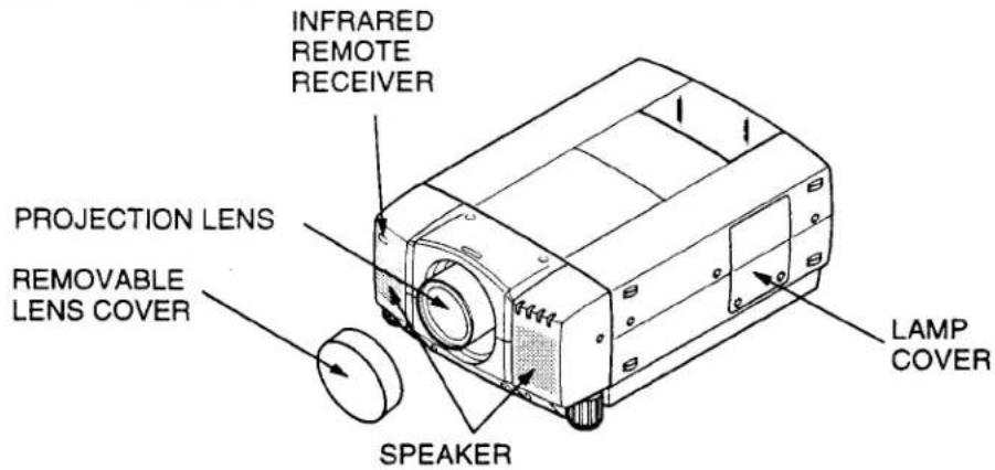
NAME OF EACH PART OF THE PROJECTOR
FRONT OF THE PROJECTOR
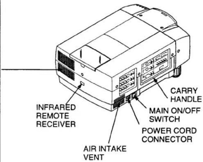
REAR OF THE PROJECTOR
EXHAUST VENT

CAUTION HOT AIR!
Air blown from the exhaust vent is hot.
Observe the following when handling your projector or choosing a location to install it.
- Keep heat-sensitive objects away from the exhaust port.
- If you set the projector on top of a metallic surface, the surface will become hot because of the hot air exhaust. Be careful when handling.
- Do not touch the cabinet near to the exhaust vent area, and especially screws and metallic parts. These parts will become hot while the projector is used.
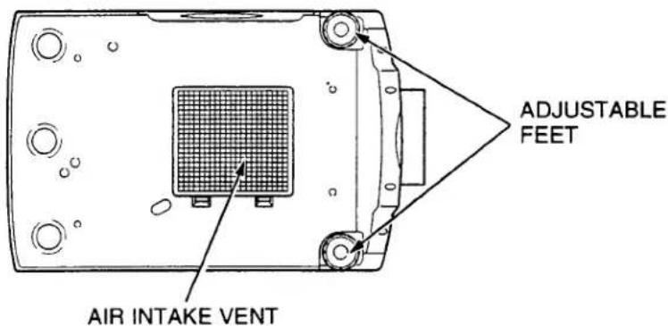
BOTTOM OF THE PROJECTOR
SETTING-UP THE PROJECTOR
POSITIONING:
● This projector is basically designed to project on a flat projection surface.
● This projector can be focused from 4.9' (1.5 m) \~ 80.7' (24.6 m).
● Refer to the figure below as an example when positioning the projector to the screen.

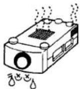
THIS PROJECTOR SHOULD BE SET IN THE WAY INDICATED. NEVER HANG THE PROJECTOR, OR FALL DOWN ON ITS SIDE. IT MAY RESULT IN FIRE HAZARD.
ROOM LIGHT
The projector should be placed in a room with limited light. Picture quality will be directly affected by lightning conditions.
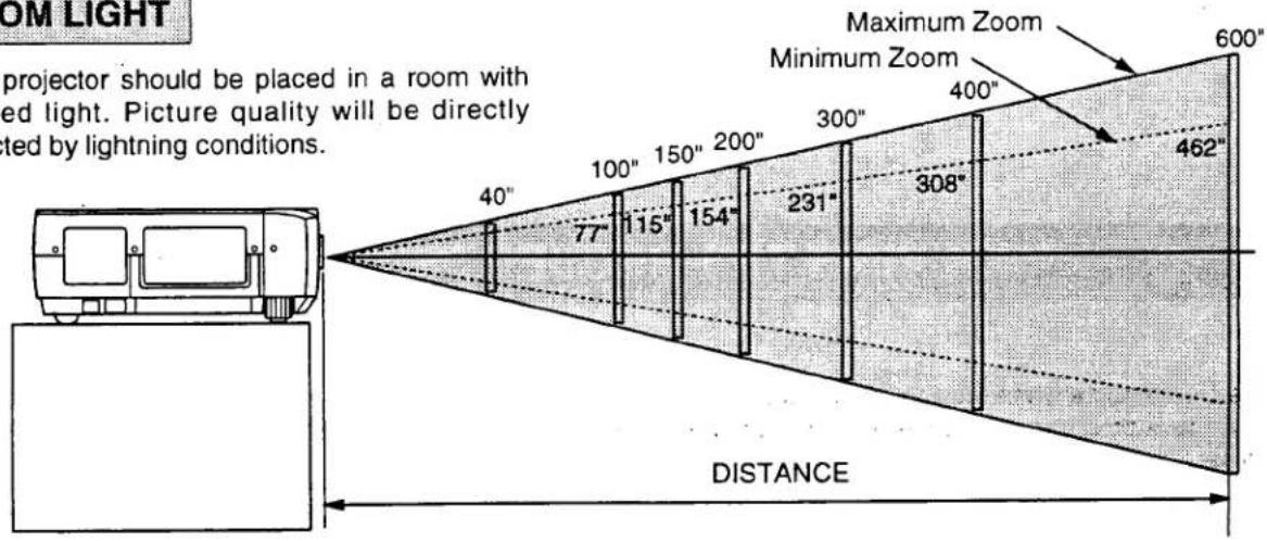
| Screen Size | Max. Zoom | 40" | 100" | 150" | 200" | 300" | 400" | 600" |
| Min. Zoom | ---- | 77" | 115" | 154" | 231" | 308" | 462" | |
| Distance | 4.9' (1.5 m) | 13.1' (4.0 m) | 20' (6.1 m) | 26.9' (8.2 m) | 40' (12.2 m) | 53.8' (16.4 m) | 80.7' (24.6 m) | |
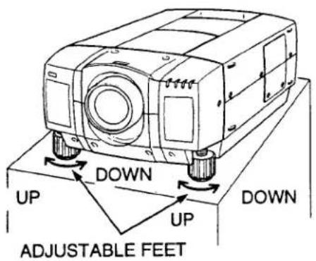
ADJUSTABLE FEET
Picture tilt and projection angle can be adjusted by twisting ADJUSTABLE FEET. Projection angle can be adjusted up to 4 degrees by rotating Adjustable Feet.
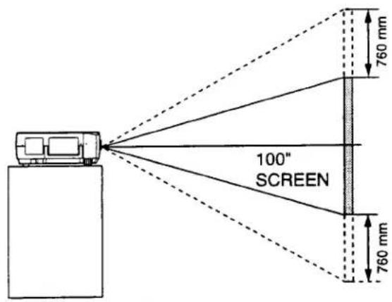
MOVE THE PROJECTED IMAGE POSITION
Adjust the projected image position (maximum 760mm downward or upward on the 100" screen) by using lens shift function. (See page 33.)
VENTILATION
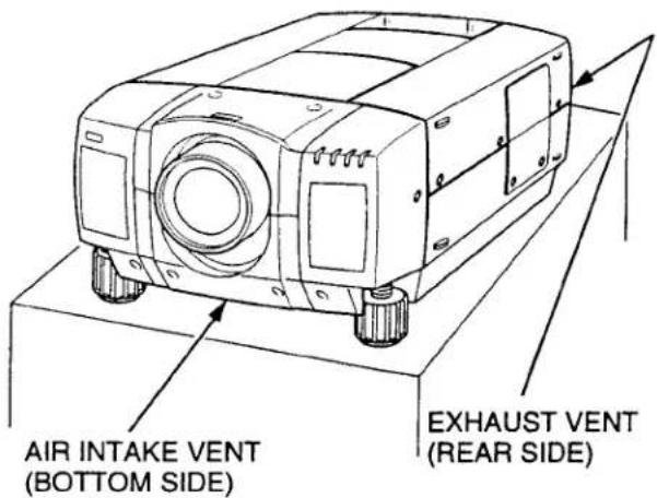
This projector is equipped with a cooling fan to protect it from overheating. Pay attention to the following to ensure the ventilation and avoid a possible risk of fire and malfunction.

● Do not cover the vents with papers or other materials.
- Keep the rear grill at least 3.3' (1m) away from any object.
● Make sure that there are no objects under the projector. An object under the projector may prevent the projector from taking the cooling air through the bottom vent.
MOVING THE PROJECTOR

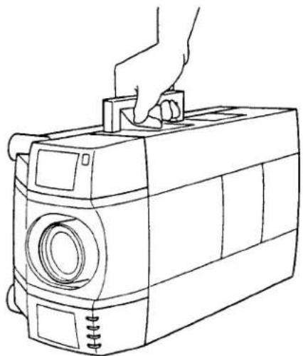
Use the carry handle when moving the projector.
Replace the lens cover and rotate the adjustable feet fully clockwise.
natural_image
Line drawing of a hand holding a camera on top, with no text or symbols presentCAUTION IN CARRYING OR TRANSPORTING THE PROJECTOR
- Do not drop or give a shock to the projector, otherwise damage or malfunction may result.
- When carrying the projector, use a Sanyo recommended Carrying Case.
- Do not transport the projector by using a courier or transport service in an unsuitable transport case. This may cause damage to the projector. To transport the projector through a courier or transport service, use a Sanyo recommended Case.
● For a carrying or transportation cases, contact a Sanyo authorized dealer.
POWER REQUIREMENTS
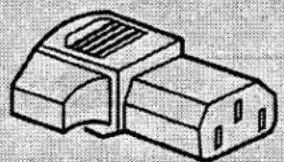
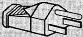
Your projector uses nominal input voltages of 100-120 VAC. The projector automatically selects the correct input voltage. The projector is designed to work with single-phase power systems having a grounded neutral conductor. To reduce the risk of electrical shock, do not plug into any other type of power system.
Consult your authorized dealer or service station if you are not sure what type of power is supplied to your building.
Projector side (Female)
natural_image
Simple line drawing of a mechanical component with no text or symbolsAC outlet side (Male)
natural_image
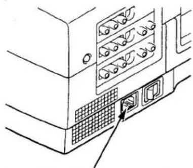
Line drawing of a server rack with multiple ports and a close-up of the next port (no text or symbols)Connect the AC power supply cord (supplied) to the projector.
The socket-outlet must be near this equipment and must be easily accessible.
TERMINAL OF THE PROJECTOR
SIDE OF THE PROJECTOR (CONNECT THE COMPUTER)
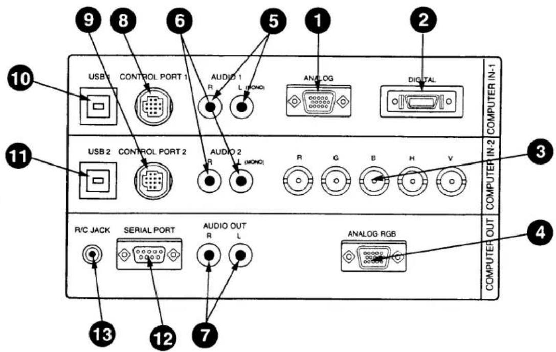
1 COMPUTER INPUT-1 TERMINAL (ANALOG HDB 15-PIN) Used to connect a computer to the projector.
2 COMPUTER INPUT-1 TERMINAL (DIGITAL MDR 20-PIN) Used to connect a computer to the projector.
3 COMPUTER INPUT-2 JACKS (BNC TYPE x 5) Used to connect a computer to the projector.
4 MONITOR OUTPUT TERMINAL (ANALOG HDB 15-PIN) Used to connect a monitor to the projector.
5 COMPUTER AUDIO INPUT-1 JACKS (R and L)
Used to connect an audio output from the computer to the projector.
6 COMPUTER AUDIO INPUT-2 JACKS (R and L)
Used to connect an audio output from the computer to the projector.
7 AUDIO MONITOR OUTPUT JACKS (R and L)
Used to connect an audio input from audio equipment to the projector.
8 CONTROL PORT-1 CONNECTOR
Used to connect a mouse cable to the projector.
9 CONTROL PORT-2 CONNECTOR
Used to connect a mouse cable to the projector.
10 USB PORT-1 CONNECTOR
Used to connect a computer to the projector.
11 USB PORT-2 CONNECTOR Used to connect a computer to the projector.
12 SERIAL PORT TERMINAL (DB9) Used to connect a computer to the projector.
13 WIRED REMOTE JACK
When using the wired remote control, connect the remote cable to this jack.
SIDE OF THE PROJECTOR (CONNECT THE VIDEO EQUIPMENT)
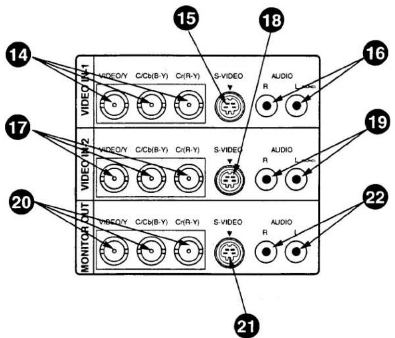
14 VIDEO INPUT JACKS-1 (BNC TYPE x 3)
Used to connect a video source to the projector.
Used to connect a S-VHS video source to the projector.
16 AUDIO INPUT JACKS-1 (R and L)
Used to connect an audio source to the projector.
17 VIDEO INPUT JACKS-2 (BNC TYPE x 3)
Used to connect a video source to the projector.
18 S-VIDEO INPUT JACK-2
Used to connect a S-VHS video source to the projector.
19 AUDIO INPUT JACKS-2 (R and L)
Used to connect an audio source to the projector.
20 VIDEO MONITOR OUTPUT JACKS (BNC TYPE x 3)
Permits video connection to a monitor.
21 VIDEO MONITOR (S-VIDEO) OUTPUT JACK
Permits S-VHS video connection to a monitor.
22 AUDIO MONITOR OUTPUT JACKS (R and L)
Permits audio connection to a monitor.
CONNECTING THE COMPUTER
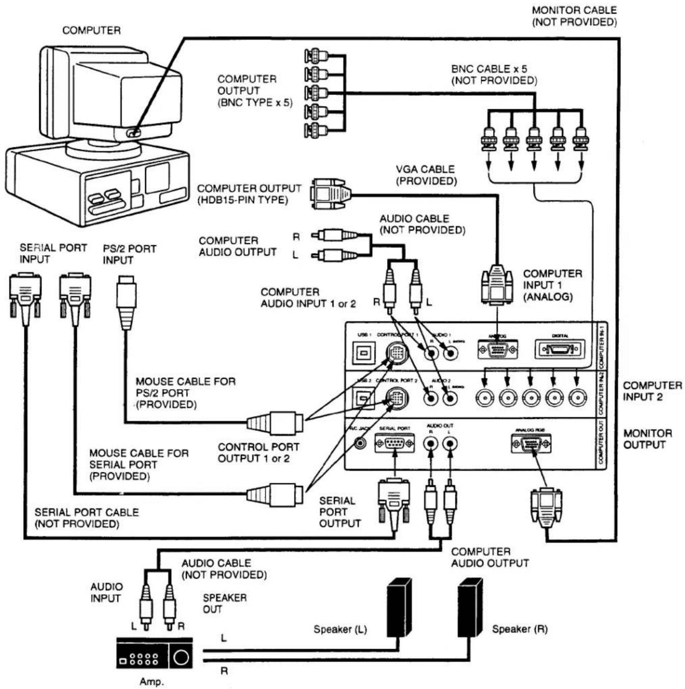
CONNECTING TO THE COMPUTER INPUT 1 TERMINAL (ANALOG HDB 15-PIN)
Personal computers can be connected to the HDB15-pin (VGA) terminal on the projector.
- Connect the computer to these terminals using the VGA cable and VGA/MAC adapter (provided).
CAUTION: For projectors, the VGA cable provided is designed to reduce RFI (Radio Frequency Interference) emissions. For regulatory compliance reasons, this cable must be used and must not be replaced by any other cable.
CONNECTING TO THE COMPUTER INPUT 1 TERMINAL (DIGITAL MDR 20-PIN)
Digital output signal from the computer can be connected to the DIGITAL terminal (MDR 20-pin). When using this input, Graphic Accelerator Board designed for this projector should be installed into your computer and set-up the computer configuration following instruction included in the Graphic Accelerator Board package. Refer to DIGITAL INPUT CONNECTION on page 15 and 17.
CONNECTING TO THE COMPUTER INPUT 2 JACKS (BNC x 5)
Personal computers can be connected to the computer input (Red, Green, Blue, Horiz. Sync. and Vert. Sync.) on the projector.
- Connect the computer to these jacks using the BNC cables (not provided).
CONNECTING TO THE COMPUTER AUDIO INPUT JACKS (1 and 2)
- Connect audio outputs from your computer to these jacks using the audio cable (not provided).
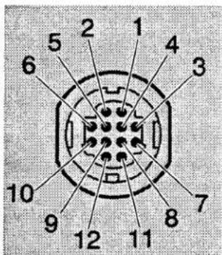
CONNECTING TO THE MULTI-POLE 12-PIN (CONTROL PORT) CONNECTORS (1 and 2,
- When the computer is operated by projector's remote control unit, connect three different type of cables (provided) between projector control port and computer mouse port or serial port.
| COMPUTER TYPE | CABLE |
| IBM Compatible computer with PS/2 mouse port. | Mouse Cable for PS/2 port. |
| IBM Compatible computer with serial port. | Mouse Cable for Serial port. |
| Apple Machintosh computer with ADB mouse port. | Mouse Cable for ADB port. |
■ CONTROL PORT
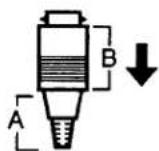
Disconnect control port cable with following steps.
-
Hold the portion (A) of the connector with one hand.
-
Pull the portion (B) arrow direction and remove connector.
CONNECTING TO THE MONITOR OUTPUT TERMINAL (ANALOG HDB 15-PIN)
This terminal output the information of the selected computer source being viewed on the screen (Computer 1 or Computer 2). When video source ("Video 1" or "Video 2") is selected, this terminal outputs Computer 1 input information.
An external monitor can be connected to the HDB15-pin (VGA) terminal on the projector.
- Connect the monitor to this terminal using the VGA cable (not provided).
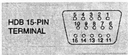
Pin No./Signal
1 Red input
2 Green input
3 Blue input
4 Sense 2
5 Ground (Horiz.sync.)
6 Ground (Red)
7 Ground (Green)
8 Ground (Blue)
9 Non Connect
10 Ground (Vert. sync.)
11 Sense 0
12 Sense 1
13 Horiz. sync
14 Vert. sync
15 Reserved
Pin No./Signal
CONNECTING TO THE AUDIO MONITOR OUTPUT (VARIABLE) JACKS
These jacks will contain the audio information of the selected program source being viewed on the screen (Computer 1, Computer 2, Video 1 or Video 2). If you have selected program source Computer 2 the audio signal connected to the Computer 2 audio input jack will be available at the audio monitor output jacks.
Use RCA type audio for connection.
- If the audio input of the audio equipment is stereo, be sure to connect the right and left channels to the respective right and left jacks.
If the audio input of the audio equipment is monaural, connect it to the left jack.
CONNECTING TO THE SERIAL PORT (DB 9-PIN) TERMINAL
- If you control the projector by computer, you must connect a cable (not provided) from your computer to this terminal.
■ SERIAL PORT
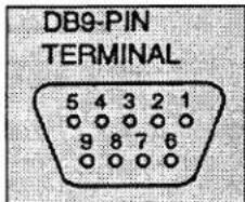
CONNECTING TO THE USB PORT CONNECTORS (1 and 2)
This Projector is designed for connecting with USB Port of the computer or peripheral equipment that is to be standard.
USB PORT
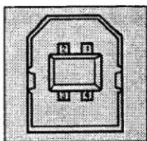
natural_image
Pure electrical circuit lines without any symbols| 1 | Vcc |
| 2 | - Data |
| 3 | + Data |
| 4 | Ground |
CONNECTING AN IBM-COMPATIBLE DESKTOP COMPUTER
flowchart
graph TD
    A["COMPUTER"] --> B["BNC CABLE x 5 (NOT PROVIDED)"]
    B --> C["VGA CABLE (PROVIDED)"]
    C --> D["COMPUTER INPUT 1 (ANALOG)"]
    D --> E["COMPUTER OUTPUT 1 or 2"]
    E --> F["MOUSER CABLE FOR PS/2 PORT (PROVIDED)"]
    F --> G["CONTROL PORT OUTPUT 1 or 2"]
    G --> H["SERIAL PORT CABLE (NOT PROVIDED)"]
    H --> I["AUDIO CABLE (NOT PROVIDED)"]
    I --> J["MONITOR CABLE (NOT PROVIDED)"]
    J --> K["COMPUTER INPUT 2"]
    K --> L["COMPUTER OUTPUT"]
    L --> M["Speaker (R)"]
    M --> N["Speaker (L)"]
    N --> O["AUDIO OUT"]
    O --> P["UNIC JACKET SERIAL PORT"]
    P --> Q["UNIC JACKET AUDIO OUT"]
    Q --> R["UNIC JACKET AUDIO CABLE (NOT PROVIDED)"]
    R --> S["SERIAL PORT OUTPUT"]
    S --> T["SERIAL PORT CABLE (NOT PROVIDED)"]
    T --> U["AUDIO CABLE (NOT PROVIDED)"]
    U --> V["LAMP"]
    V --> W["R"]
    W --> X["L"]
    X --> Y["R"]
    Y --> Z["L"]
    Z --> AA["Speaker (L)"]
    AA --> AB["Speaker (R)"]
    AB --> AC["COMPUTER AUDIO OUTPUT"]
    AC --> AD["COMPUTER OUTPUT 1"]
    AD --> AE["COMPUTER OUTPUT 2"]
NOTE: When connecting the cable, the power cords of both the projector and the external equipment should be disconnected from AC outlet. Turn the projector and peripheral equipment on before the computer is switched on.
CONNECTING AN IBM-COMPATIBLE DESKTOP COMPUTER DIGITAL INPUT CONNECTION)
NOTE:
Before using with digital connection, install (Plug in) Graphic Accelerator Board (included within projector) into PCI bus slot of the computer and set up the computer following instructions in the Graphic Accelerator Board package.
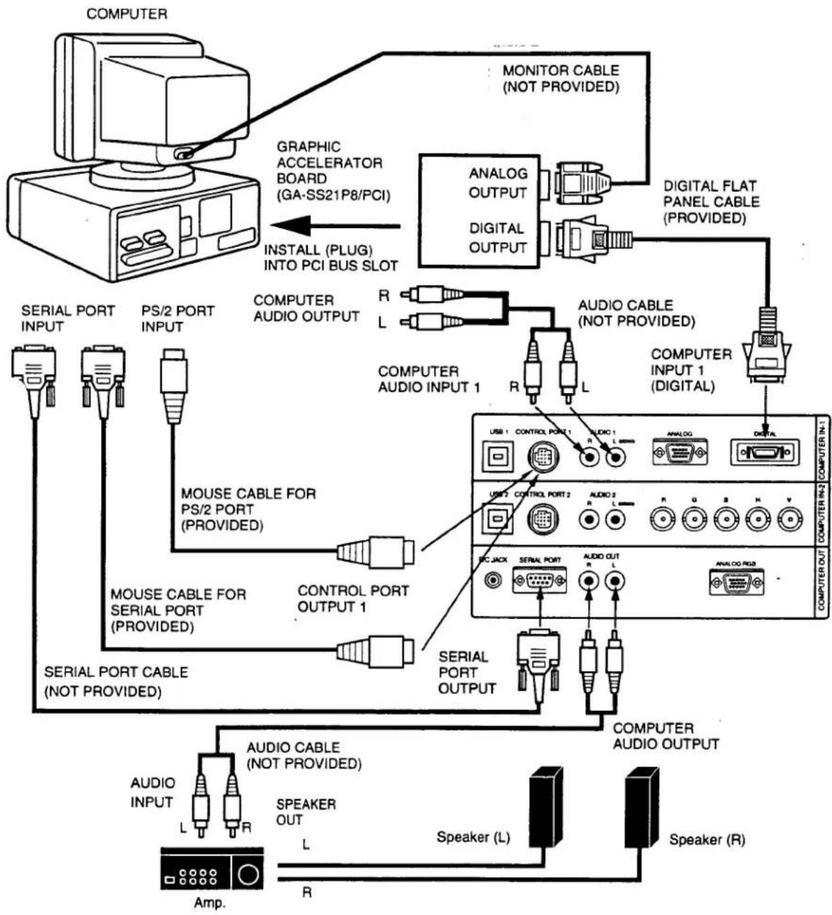
flowchart
graph TD
    A["COMPUTER"] --> B["GRAPHIC ACCELERATOR BOARD (GA-SS21P8/PCI)"]
    B --> C["INSTALL (PLUG) INTO PCI BUS SLOT"]
    C --> D["ANALOG OUTPUT"]
    C --> E["DIGITAL OUTPUT"]
    D --> F["MONITOR CABLE (NOT PROVIDED)"]
    E --> G["DIGITAL FLAT PANEL CABLE (PROVIDED)"]
    F --> H["MOUSER CABLE FOR PS/2 PORT (PROVIDED)"]
    G --> I["MOUSER CABLE FOR SERIAL PORT (PROVIDED)"]
    H --> J["CONTROL PORT OUTPUT 1"]
    I --> K["CONTROL PORT OUTPUT"]
    J --> L["SERIAL PORT CABLE (NOT PROVIDED)"]
    K --> M["SERIAL PORT CABLE"]
    L --> N["AUDIO CABLE (NOT PROVIDED)"]
    M --> O["AUDIO CABLE"]
    N --> P["AMP."]
    O --> Q["Speaker (L)"]
    P --> R["R"]
    Q --> S["Speaker (R)"]
    style A fill:#f9f,stroke:#333
    style B fill:#ccf,stroke:#333
    style C fill:#cfc,stroke:#333
    style D fill:#fcc,stroke:#333
    style E fill:#fcc,stroke:#333
    style F fill:#cff,stroke:#333
    style G fill:#cff,stroke:#333
    style H fill:#ffc,stroke:#333
    style I fill:#ffc,stroke:#333
    style J fill:#ffc,stroke:#333
    style K fill:#ffc,stroke:#333
    style L fill:#ffc,stroke:#333
    style M fill:#ffc,stroke:#333
    style N fill:#ffc,stroke:#333
    style O fill:#ffc,stroke:#333
    style P fill:#ffc,stroke:#333
    style Q fill:#ffc,stroke:#333
    style R fill:#ffc,stroke:#333
..JTE: When connecting the cable, the power cords of both the projector and the external equipment should be disconnected from AC outlet. Turn the projector and peripheral equipment on before the computer is switched on.
CONNECTING AN IBM-COMPATIBLE LAPTOP COMPUTER
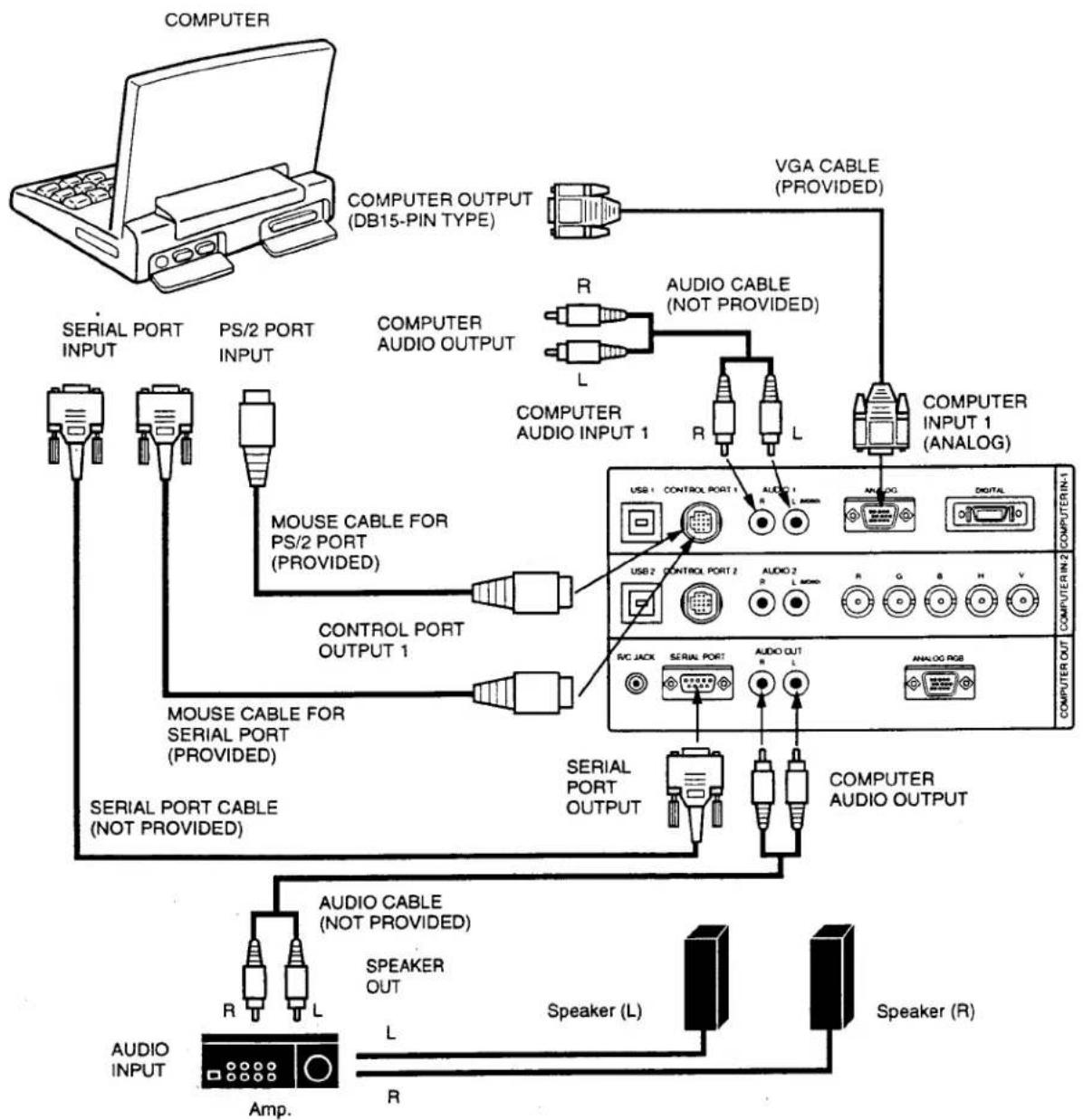
flowchart
graph TD
    A["COMPUTER"] --> B["COMPUTER OUTPUT (DB15-PIN TYPE)"]
    B --> C["VGA CABLE (PROVIDED)"]
    C --> D["COMPUTER AUDIO INPUT 1"]
    C --> E["COMPUTER AUDIO CABLE (NOT PROVIDED)"]
    D --> F["CONTROL PORT OUTPUT 1"]
    E --> G["CONTROL PORT 2"]
    F --> H["USER 1 CONTROL PORT 1"]
    G --> I["USER 2 CONTROL PORT 2"]
    H --> J["AVC JACK SERIAL PORT"]
    I --> K["AVIO OUT"]
    J --> L["ANALOG USB"]
    K --> M["ANALOG RADIO"]
    L --> N["COMPUTER AUDIO OUTPUT"]
    M --> O["COMPUTER AUDIO CABLE (NOT PROVIDED)"]
    N --> P["AUDIO CABLE (NOT PROVIDED)"]
    O --> Q["SPEAKER OUT"]
    P --> R["Speaker (L)"]
    Q --> S["AUDIO INPUT Amp."]
    R --> T["Speaker (R)"]
NOTE: When connecting the cable, the power cords of both the projector and the external equipment should be disconnected from AC outlet. Turn the projector and peripheral equipment on before the computer is switched on.
CONNECTING AN IBM-COMPATIBLE LAPTOP COMPUTER IGITAL INPUT CONNECTION)
NOTE: This connection need optionally saled Graphic Accelerator PC card (GA-SM02P2/CB). For this information, contact to your authorized dealer.
Before using with digital connection, install (Plug in) Graphic Accelerator PC card into card bus slot of the computer and set up the computer following instructions in the Graphic Accelerator PC card package.
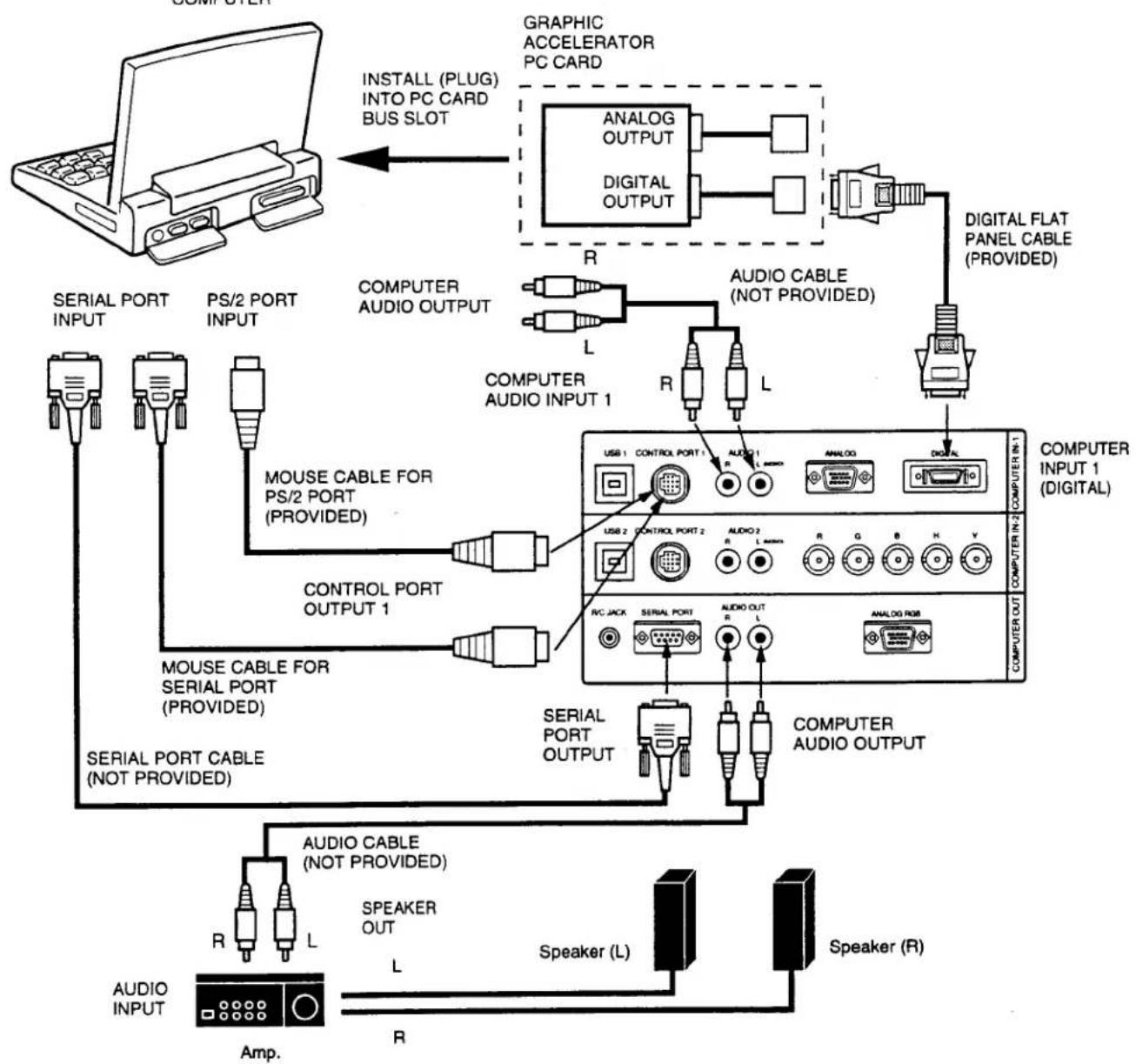
flowchart
graph TD
    A["Computer"] --> B["LOGIC Display"]
    B --> C["PS/2 PORT INPUT"]
    C --> D["MSI Portugal"]
    D --> E["MOUSE CABLE FOR PS/2 PORT (PROVIDED)"]
    E --> F["CONTROL PORT OUTPUT 1"]
    F --> G["MSI Portugal"]
    G --> H["SERIAL PORT CABLE (NOT PROVIDED)"]
    H --> I["AUDIO CABLE (NOT PROVIDED)"]
    I --> J["Speaker (L)"]
    J --> K["Audio Output"]
    K --> L["SERIAL PORT OUTPUT"]
    L --> M["COMPUTER AUDIO OUTPUT"]
    M --> N["COMPUTER IN-2 (DIGITAL)"]
    N --> O["COMPUTER INPUT 1 (DIGITAL)"]
    O --> P["Digital FLAT PANEL CABLE (PROVIDED)"]
    P --> Q["ANALOG OUTPUT"]
    Q --> R["ANALOG"]
    R --> S["ANALOG RUB"]
    S --> T["ACOLO"]
    T --> U["ACOLO 2"]
    U --> V["ACOLO 1"]
    V --> W["USB 1"]
    W --> X["CONTROL PORT 1"]
    X --> Y["AMOUNT"]
    Y --> Z["ACOLO CABLE (NOT PROVIDED)"]
    Z --> AA["Speaker (R)"]
    AA --> AB["Audio Output"]
    AB --> AC["ACOLO"]
    AC --> AD["ACOLO 2"]
    AD --> AE["ACOLO 1"]
    AE --> AF["USB 2"]
    AF --> AG["CONTROL PORT 2"]
    AG --> AH["AMOUNT"]
    AH --> AI["ACOLO CABLE (NOT PROVIDED)"]
    AI --> AJ["Speaker (L)"]
    AJ --> AK["Audio Output"]
    AK --> AL["ACOLO"]
    AL --> AM["ACOLO 2"]
    AM --> AN["ACOLO 1"]
    AN --> AO["USB 1"]
    AO --> AP["CONTROL PORT 1"]
    AP --> AQ["AMOUNT"]
    AQ --> AR["ACOLO CABLE (NOT PROVIDED)"]
    AR --> AS["Speaker (L)"]
    AS --> AT["Audio Output"]
DTE: When connecting the cable, the power cords of both the projector and the external equipment should be disconnected from AC outlet. Turn the projector and peripheral equipment on before the computer is switched on.
CONNECTING A MACINTOSH DESKTOP COMPUTER
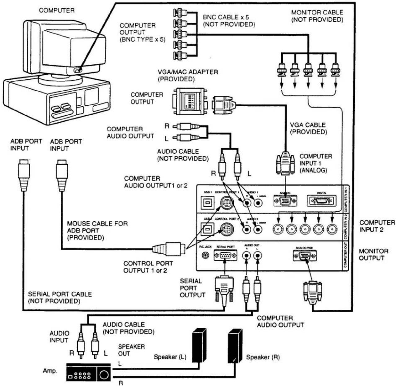
flowchart
graph TD
    A["COMPUTER"] --> B["BNC CABLE x 5 (NOT PROVIDED)"]
    A --> C["MONITOR CABLE (NOT PROVIDED)"]
    B --> D["VGA/MAC ADAPTER (PROVIDED)"]
    C --> E["VGA CABLE (PROVIDED)"]
    D --> F["COMPUTER OUTPUT"]
    D --> G["COMPUTER AUDIO OUTPUT"]
    E --> H["COMPUTER AUDIO OUTPUT1 or 2"]
    E --> I["COMPUTER INPUT 1 (ANALOG)"]
    F --> J["MOUSE CABLE FOR ADB PORT (PROVIDED)"]
    G --> K["MOUSER CABLE (NOT PROVIDED)"]
    H --> L["CONTROL PORT OUTPUT 1 or 2"]
    I --> M["CONTROL PORT OUTPUT 2"]
    J --> N["SERIAL PORT CABLE (NOT PROVIDED)"]
    K --> O["SERIAL PORT OUTPUT"]
    L --> P["SERIAL PORT CABLE (NOT PROVIDED)"]
    M --> Q["SERIAL PORT CABLE (NOT PROVIDED)"]
    N --> R["AUDIO CABLE (NOT PROVIDED)"]
    O --> S["AUDIO CABLE (NOT PROVIDED)"]
    P --> T["SPEAKER OUT L Speaker (L)"]
    Q --> U["Speaker (L)"]
    R --> V["Amp."]
    S --> W["R"]
    T --> X["Speaker (R)"]
    style A fill:#f9f,stroke:#333
    style B fill:#ccf,stroke:#333
    style C fill:#ccf,stroke:#333
    style D fill:#cfc,stroke:#333
    style E fill:#cfc,stroke:#333
    style F fill:#fcc,stroke:#333
    style G fill:#fcc,stroke:#333
    style H fill:#fcc,stroke:#333
    style I fill:#fcc,stroke:#333
    style J fill:#fcc,stroke:#333
    style K fill:#fcc,stroke:#333
    style L fill:#fcc,stroke:#333
    style M fill:#fcc,stroke:#333
    style N fill:#fcc,stroke:#333
    style O fill:#fcc,stroke:#333
    style P fill:#fcc,stroke:#333
    style Q fill:#fcc,stroke:#333
    style R fill:#fcc,stroke:#333
    style S fill:#fcc,stroke:#333
    style T fill:#fcc,stroke:#333
    style U fill:#fcc,stroke:#333
    style V fill:#fcc,stroke:#333
Set the dip switches as shown in the table below depending on the RESOLUTION MODE that you want to use before you turn on the projector and computer.
| RESOLUTION MODE | SW1 | SW2 | SW3 | SW4 | SW5 | SW6 |
| 13" MODE (640 x 480) | ON | ON | OFF | OFF | OFF | OFF |
| 16" MODE (832 x 624) | OFF | ON | OFF | ON | OFF | OFF |
| 19" MODE (1024 x 768) | OFF | ON | ON | OFF | OFF | OFF |
| 21" MODE (1152 x 870) | ON | ON | ON | ON | OFF | OFF |
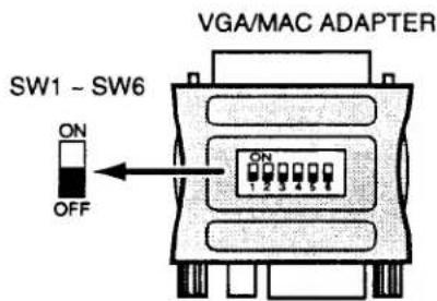
NOTE: When connecting the cable, the power cords of both the projector and the external equipment should be disconnected from AC outlet. Turn the projector and peripheral equipment on before the computer is switched on.
CONNECTING A MACINTOSH POWERBOOK COMPUTER
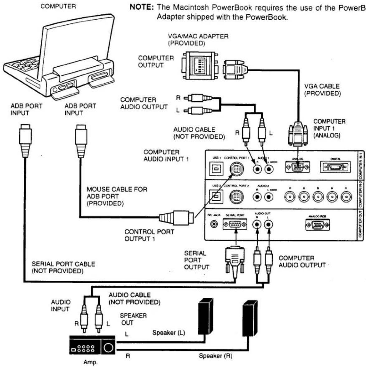
flowchart
graph TD
    A["COMPUTER"] --> B["ADB PORT INPUT"]
    A --> C["ADB PORT INPUT"]
    A --> D["COMPUTER AUDIO OUTPUT"]
    D --> E["MOUSE CABLE FOR ADB PORT (PROVIDED)"]
    D --> F["CONTROL PORT OUTPUT 1"]
    F --> G["SERIAL PORT CABLE (NOT PROVIDED)"]
    G --> H["AUDIO CABLE (NOT PROVIDED)"]
    H --> I["Speaker (L)"]
    I --> J["Speaker (R)"]
    J --> K["AMP."]
    L["VGA/MAC ADAPTER (PROVIDED)"] --> M["COMPUTER OUTPUT"]
    M --> N["R"]
    M --> O["L"]
    P["AUDIO CABLE (NOT PROVIDED)"] --> Q["CONTROL PORT OUTPUT 1"]
    R["COMPUTER AUDIO INPUT 1"] --> S["USER 1 CONTROL PORT 1"]
    T["COMPUTER AUDIO OUTPUT"] --> U["USER 2 CONTROL PORT 2"]
    V["COMPUTER AUDIO OUTPUT"] --> W["USER 3 CONTROL PORT 3"]
    X["COMPUTER AUDIO OUTPUT"] --> Y["USER 4 CONTROL PORT 4"]
    Z["COMPUTER AUDIO OUTPUT"] --> AA["USER 5 CONTROL PORT 5"]
    AB["COMPUTER AUDIO OUTPUT"] --> AC["USER 6 CONTROL PORT 6"]
    AD["COMPUTER AUDIO OUTPUT"] --> AE["USER 7 CONTROL PORT 7"]
    AF["COMPUTER AUDIO OUTPUT"] --> AG["USER 8 CONTROL PORT 8"]
    AH["COMPUTER AUDIO OUTPUT"] --> AI["USER 9 CONTROL PORT 9"]
    AJ["COMPUTER AUDIO OUTPUT"] --> AK["USER 10 CONTROL PORT 10"]
Set the dip switches as shown in the table below depending on the RESOLUTION MODE that you want to use before you turn on the projector and computer.
| RESOLUTION MODE | SW1 | SW2 | SW3 | SW4 | SW5 | SW6 |
| 13" MODE (640 x 480) | ON | ON | OFF | OFF | OFF | OFF |
| 16" MODE (832 x 624) | OFF | ON | OFF | ON | OFF | OFF |
| 19" MODE (1024 x 768) | OFF | ON | ON | OFF | OFF | OFF |
| MODE (1152 x 870) | ON | ON | ON | ON | OFF | OFF |
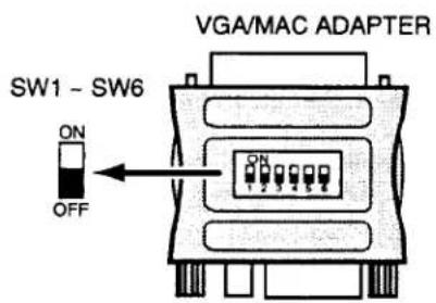
NOTE: When connecting the cable, the power cords of both the projector and the external equipment should be disconnected from AC outlet. Turn the projector and peripheral equipment on before the computer is switched on.
CONNECTING THE VIDEO EQUIPMENT
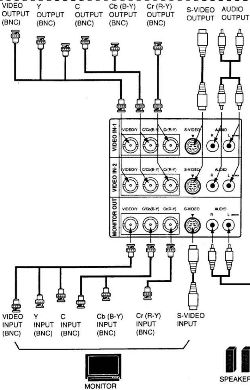
CONNECTING TO THE VIDEO INPUT JACKS (1 and 2) BNC TYPE x 3
Connect to the video outputs of a VCR, video disc player, DVD player, video camera, satellite TV tuner or other AV equipment. Connect video output from AV equipment to these jacks using the BNC cables.
The video input can be connected 3 types of signals; "COMPOSITE VIDEO", "Y/C SEPARATE VIDEO" and COMPONENT VIDEO {Y, Cb (B-Y), Cr (R-Y)}.
Set VIDEO SOURCE of each video input (VIDEO IN-1 or VIDEO IN-2) to input video matter. (Refer to "VIDEO SOURCE SELECT" operation on page 37).
CONNECTING S-VHS VIDEO INPUT JACKS (1 and 2)
The Video input includes an extra video input jack marked S-VIDEO to allow connection to an S-VHS format VCR that has separate Y/C video signals. The S-VIDEO jack has priority over the VIDEO jack.
CONNECTING TO THE AUDIO INPUT JACKS (1 and 2)
Connect to the audio outputs of a VCR, video disc player, DVD player, video camera, satellite TV tuner or other AV equipment. Use RCA type audio cable for connection.
- If the audio signal from the AV equipment is stereo, be sure to connect the right and left channels to the respective right and left audio input jacks.
- If the external audio signal is monaural, connect it to the left jack.
CONNECTING TO THE VIDEO MONITOR OUTPUT JACKS (BNC TYPE x 3)
These jacks will contain the video information of the selected program source being viewed on the screen (Video 1 or Video 2). If you have selected program source Video 2 the video signal connected to the Video 2 video input jack will be available at the video monitor output jacks. If you select program source "Computer 1" or "Computer 2, the video signal connected to the Video 1 video input jack will be available at the video monitor output jacks.
Use BNC cable for connection.
CONNECTING TO THE S-VHS VIDEO MONITOR OUTPUT JACK
The Video monitor output includes an extra video input jack marked S-VIDEO to allow connection to an S-VHS format VCR that has separate Y/C video signals. The S-VIDEO jack has priority over the VIDEO jack.
CONNECTING TO THE AUDIO MONITOR OUTPUT JACKS
These jacks will contain the audio information of the selected program source being viewed on the screen (Video 1 or Video 2). If you have selected program source Video 2 the audio signal connected to the Video 2 audio input jack will be available at the audio monitor output jacks. If you select program source "Computer 1" or "Computer 2", the audio signal connected to the Video 1 audio input jack will be available at the audio monitor output jacks.
Use RCA type audio cable for connection.
- If the audio input of the audio equipment is stereo, be sure to connect the right and left channels to the respective right and left jacks.
- If the audio input of the audio equipment is monaural, connect it to the left jack.
CONNECTING THE VIDEO EQUIPMENT
VIDEO EQUIPMENT
Video Cassette Recorder
DVD Player
Video Disc Player
Satellite
TV Tuner
Video Camera
flowchart
graph TD
    A["VIDEO OUTPUT (BNC)"] --> B["VIDEO IN-1"]
    C["Y OUTPUT (BNC)"] --> D["VIDEO IN-2"]
    E["C OUTPUT (BNC)"] --> F["VIDEO OUT"]
    G["Cb (B-Y) OUTPUT (BNC)"] --> H["MONITOR OUT"]
    I["Cr (R-Y) OUTPUT (BNC)"] --> J["MONITOR OUT"]
    K["S-VIDEO OUTPUT"] --> L["VIDEO OUT"]
    M["AUDIO OUTPUT"] --> N["MONITOR OUT"]
    O["VIDEO INPUT (BNC)"] --> P["MONITOR OUT"]
    Q["Y INPUT (BNC)"] --> R["MONITOR OUT"]
    S["C INPUT (BNC)"] --> T["MONITOR OUT"]
    U["Cb (B-Y) INPUT (BNC)"] --> V["MONITOR OUT"]
    W["Cr (R-Y) INPUT (BNC)"] --> X["MONITOR OUT"]
    Y["S-VIDEO INPUT"] --> Z["MONITOR OUT"]
    AA["S-VIDEO OUTPUT"] --> AB["MONITOR OUT"]
    AC["S-VIDEO OUTPUT"] --> AD["MONITOR OUT"]
    AE["S-VIDEO OUTPUT"] --> AF["MONITOR OUT"]
NOTE: When connecting the cable, the power cords of both the projector and the external equipment should be disconnected from AC outlet. Turn the projector on before the peripheral equipment is switched on.
CONTROLS AND INDICATORS
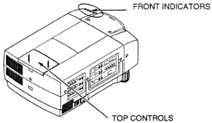
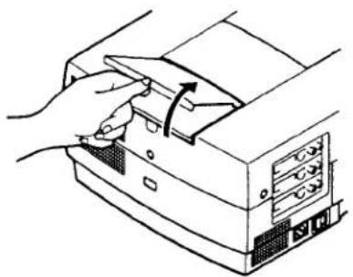
natural_image
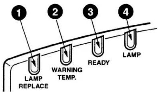
Illustration of a hand inserting a device into a computer tower (no text or symbols visible)FRONT INDICATORS
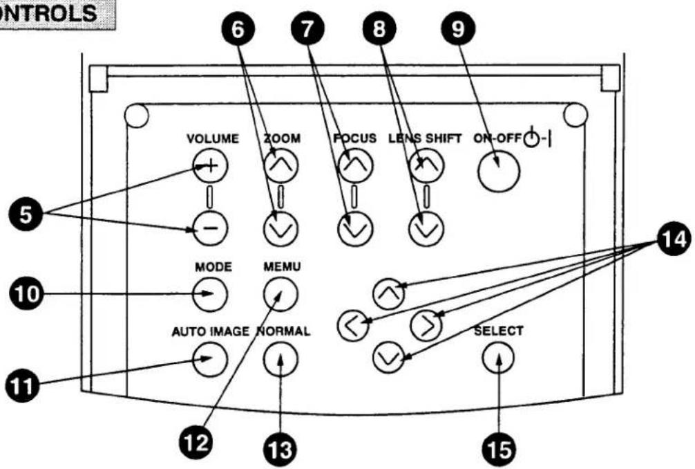
TOP CONTROLS
LAMP REPLACEMENT INDICATOR
Light is orange when the Lamp life draws to an end.
② TEMPERATURE WARNING INDICATOR
Flashes red when internal projector temperature is too high.
③ READY INDICATOR
Light is green when projector lamp is ready to be turned on.
4 LAMP POWER INDICATOR
Light is dim when the projector is on.
Light is brightened when the projector is in stand-by mode.
5 VOLUME BUTTONS
Used to adjust volume.
6 ZOOM BUTTONS
Used to operate power zoom lens.
7 FOCUS BUTTONS
Used to operate power focus system.
8 LENS SHIFT BUTTONS
Used to operate power lens shift.
9 POWER ON/OFF BUTTON
Used to turn the projector on or off.
10 MODE BUTTON
Used to select source.
(Computer 1, Computer 2, Video 1 or Video 2 Input)
AUTO IMAGE BUTTON
Used to operate the AUTO IMAGE function.
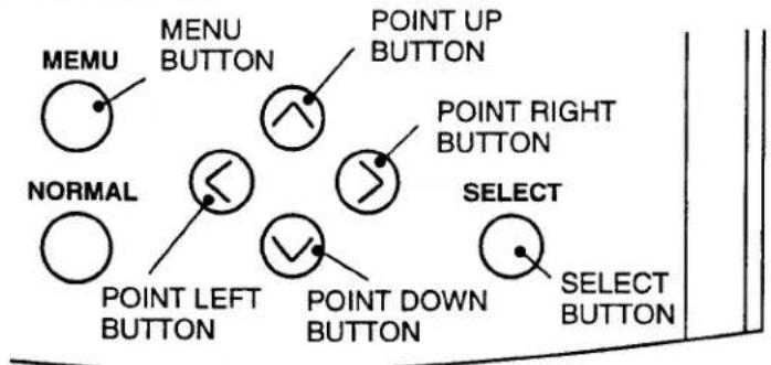
12 MENU BUTTON
This button will activate the MENU operation.
Use this button, the POINT UP/DOWN/LEFT/RIGHT buttons and the SELECT button to make adjustments to the projector's setting in MENU operation.
13 NORMAL BUTTON
Used to reset to normal picture adjustment preset by factory.
To select an item on the MENU that you want to adjust. To select an item, move the arrow by pressing these buttons (UP, DOWN, LEFT or RIGHT).
15 SELECT BUTTON
This button has different functions depending on when used. This button is used to execute the item selected, to increase or decrease the values in certain items such as CONTRAST or BRIGHTNESS.
This remote control unit is not only able to operate the projector but also usable as a wireless mouse for a PC. One pointing pad and two click buttons are used for wireless mouse operation.
Wireless mouse is usable when PC mouse pointer is displayed on the screen. When the menu or indicator of the projector is displayed on the screen instead of the PC mouse pointer, the wireless mouse cannot be used.
NOTE: To use the unit as a PC wireless mouse, connect the projector to the PC with the attached cable. Signals from the projector are transmitted to the PC, enabling the remote control unit of the projector to be used as a PC wireless mouse. (Refer to "CONNECTING THE PROJECTOR" in pages 14 to 19 for the connection.)
LASER POINTER button
This remote control emits a laser beam light as the Laser Pointer from the Laser Light Window.
When the LASER POINTER button is pressed, laser light goes on: when the button is released, light goes off.
Laser light is emitted with the RED light which tells the laser beam being emitted.
The laser emitted is a class II laser; therefore, do not look into the laser light window or shine the laser beam on yourself or other people. The three marks to the right are the caution labels for the laser beam.
CAUTION-use of controls or adjustments or performance of procedures other than those specified herein may result hazardous radiation exposure.
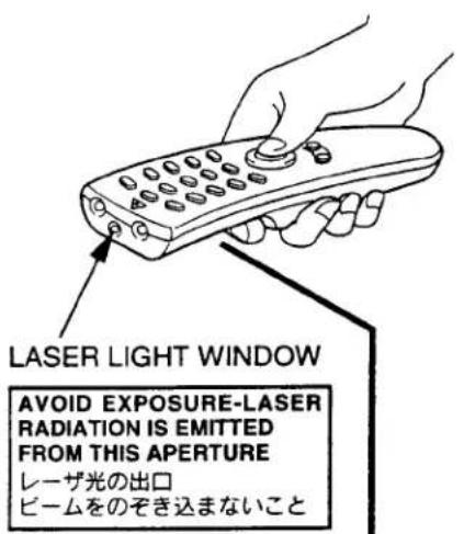
CLASS II LASER PRODUCT This product is complied with 21 CFR part 1040.10
natural_image
Technical line drawing of a mechanical component with a numbered label (19) pointing to a feature on the side (no text or symbols beyond the number)
COMPUTER SELECT BUTTON
Used to select computer mode. (Computer 1 or Computer 2 Input)

VIDEO SELECT BUTTON
Used to select video mode. (Video 1 or Video 2 Input)

POWER ON/OFF BUTTON
Used to turn the projector on or off.

VOLUME BUTTONS
Used to adjust volume.

ZOOM BUTTON
Used to select power zoom lens adjust.

P-TIMER BUTTON
Used to operate the P-TIMER function.

FOCUS BUTTON
Used to select focus adjust.

FREEZE/NO SHOW BUTTON
Used to freeze on-screen image or change the screen into black image.

SOUND MUTE BUTTON
Used to mute sound.

LENS SHIFT BUTTON
Used to select power lens shift.

CURSOR BUTTON
Used to display CURSOR on the screen.

AUTO IMAGE BUTTON
Used to operate the AUTO IMAGE function.
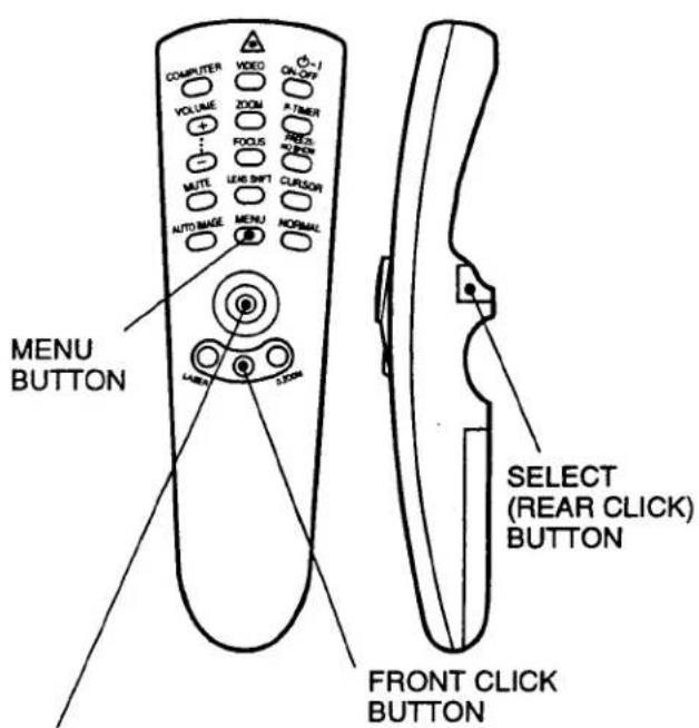
MENU BUTTON
This button will activate the MENU operation. Use this button, the POINT UP/DOWN/LEFT/RIGHT button and the SELECT (REAR CLICK) button to make adjustments to the projector's setting in MENU operation.

NORMAL BUTTON
Use to reset to normal picture adjustment preset by factory.

When in use as a remote for the projector
To select an item on the MENU that you want to adjust. To select an item, move the arrow by pressing the pad upward, downward, leftward or rightward.
Used to operate power zoom lens, power focus system or power lens shift by pressing the pad either upward or downward.
When in use as a wireless mouse
Used to move the pointer. The pointer is moved according to the direction you are pressing.

LASER BUTTON
When this button is pressed, laser light goes on; when the button is released, light goes off.

FRONT CLICK BUTTON
When in use as a remote for the projector
Used to compress the image in D.ZOOM mode.
When in use as a wireless mouse
This button has the same function as the right button in a PC mouse.

DIGITAL ZOOM BUTTON
Used to select digital zoom function.

SELECT (REAR CLICK) BUTTON
When in use as a remote for the projector.
This button has different functions depending on when used. This button is used to execute the item selected, to increase or decrease the values in certain items such as CONTRAST or BRIGHTNESS.
When in use as a wireless mouse
This button has the same function as the left button in a PC mouse.
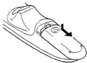
Remote Control Battery Installation
1 Remove the battery compartment lid.
natural_image
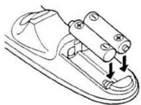
Line drawing of a shoe sole with a black arrow indicating the sole point (no text or symbols present)2 Slide the batteries into the compartment.
Note: For correct polarity (+ and - terminal), be sure the battery terminals are in contact with the pins in the compartment.
natural_image
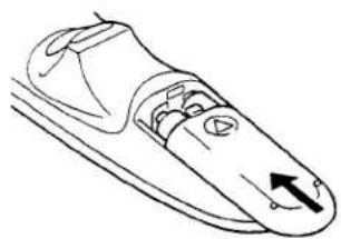
Technical line drawing of a mechanical component with two downward arrows indicating assembly or force (no text or symbols)3 Replace the compartment lid.
natural_image
Line drawing of a mechanical component with an arrow indicating direction (no text or symbols)Using the Remote Control Unit
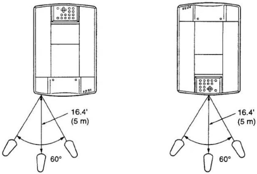
Point the remote control toward the projector (Receiver window) whenever pressing the buttons. Maximum operating range for the remote control is about 16.4' (5m) and 60° front and rear of the projector.

To insure safe operation, please observe the following precautions:
● Use (2) AA type alkaline batteries.
● Change two batteries at the same time.
● Do not use a new battery with a used battery.
● Avoid contact with water.
● Do not drop the remote control unit.
- If batteries have leaked on the remote control, carefully wipe the case clean and load new batteries.
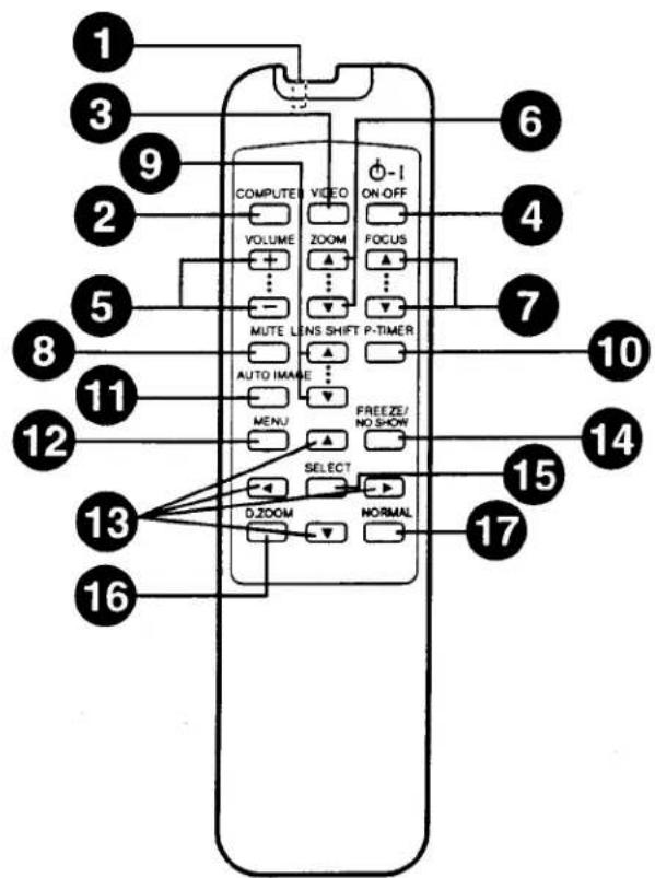
WIRELESS/WIRED REMOTE CONTROL UNIT
WIRED REMOTE JACK
When using the wired remote control, connect the remote cable to this jack.
2 COMPUTER SELECT BUTTON
Used to select computer mode. (Computer 1 or Computer 2 Input)
3 VIDEO SELECT BUTTON
Used to select video mode. (Video 1 or Video 2 Input)
4 POWER ON/OFF BUTTON
Used to turn projector on or off.
5 VOLUME BUTTONS
Used to adjust volume.
6 ZOOM BUTTONS
Used to operate power zoom lens.
7 FOCUS BUTTONS
Used to operate power focus system.
8 SOUND MUTE BUTTON
Used to mute sound.
9 LENS SHIFT BUTTONS
Used to operate power lens shift.
P-TIMER BUTTON
Used to operate the P-TIMER function.
11 AUTO IMAGE BUTTON
Used to operate the AUTO IMAGE function.
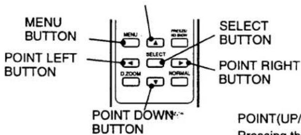
12 MENU BUTTON
This button will activate the MENU operation.
Use this button, the POINT UP/DOWN/LEFT/RIGHT buttons and the SELECT button to make adjustments to the projector's setting in MENU operation.
To select an item on the MENU that you want to adjust. To select an item, move the arrow by pressing these buttons (UP, DOWN, LEFT or RIGHT).
14 FREEZE/NO SHOW BUTTON
Used to freeze on-screen image or change the screen into black image.
15 SELECT BUTTON
This button has different functions depending on when used. This button is used to execute the item selected, to increase or decrease the values in certain items such as CONTRAST or BRIGHTNESS.
16 DIGITAL ZOOM BUTTON
Use to select digital zoom function.
17 NORMAL BUTTON
Used to reset to normal picture adjustment preset by factory.
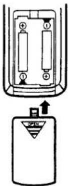
Remote Control Battery Installation
1 Remove the battery compartment lid.
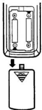
2 Slide the batteries into the compartment.
Note: For correct polarity (+ and - terminal), be sure the battery terminals are in contact with the pins in the compartment.
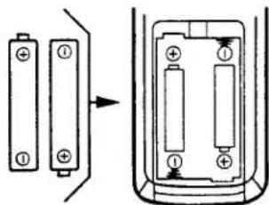
3 Replace the compartment lid.
natural_image
Diagram of a battery pack and its internal circuit with an AC input (no text or symbols)The remote control unit can be used as wireless or wired remote control.
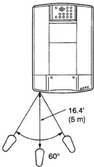
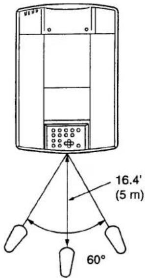
Using the Remote Control Unit (wireless)
Point the remote control toward the projector (Receiver window) whenever pressing the buttons. Maximum operating range for the remote control is about 16.4' (5m) and 60° front and rear of the projector.
Using the Remote Control Unit (wired)
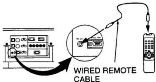
Connect a remote control cable to R/C jacks located on the wireless/wired remote control unit and the side of the projector.

To insure safe operation, please observe the following precautions:
● Use (2) AA type alkaline batteries.
● Change two batteries at the same time.
● Do not use a new battery with a used battery.
● Avoid contact with water.
● Do not drop the remote control unit.
- If batteries have leaked on the remote control, carefully wipe the case clean and load new batteries.
CONTROL THE PROJECTOR
The projector has two types of operation: DIRECT OPERATION and MENU OPERATION. DIRECT OPERATION allows you to operate the projector by using one button without showing the MENU. In MENU OPERATION mode, you display menus where you can adjust the projector's settings. Follow the instruction for each control.
DIRECT OPERATION
| ADJUST ITEM | TOP CONTROL OF THE PROJECTOR | WIRELESS/WIRED REMOTE CONTROL | WIRELESS REMOTE CONTROL |
| POWER ON/OFF | POWER ON-OFF | POWER ON-OFF | POWER ON-OFF |
| MODE SELECT | MODE | COMPUTERVIDEO | COMPUTERVIDEO |
| SOUND VOLUME | VOLUME (+) and (-) | VOLUME (+) and (-) | VOLUME (+) and (-) |
| SOUND MUTE | NOT AVAILABLE | MUTE | MUTE |
| ZOOM | ZOOM (▲) and (▼) | ZOOM (▲) and (▼) | ZOOMPOINT (UP/DOWN) |
| OCUS | FOCUS (▲) and (▼) | FOCUS (▲) and (▼) | FOCUSPOINT (UP/DOWN) |
| LENS SHIFT | LENS SHIFT (▲) and (▼) | LENS SHIFT (▲) and (▼) | LENS SHIFTPOINT (UP/DOWN) |
| DIGITAL ZOOM | NOT AVAILABLE | D. ZOOMSELECTPOINT(UP/DOWN/LEFT/RIGHT) | D. ZOOMSELECT (REAR CLICK)FRONT CLICKPOINT(UP/DOWN/LEFT/RIGHT) |
| NORMAL PICTURE | NORMAL | NORMAL | NORMAL |
| FREEZE PICTURE | NOT AVAILABLE | FREEZE/NO SHOW | FREEZE/NO SHOW |
| NO SHOW | NOT AVAILABLE | FREEZE/NO SHOW | FREEZE/NO SHOW |
| P-TIMER | NOT AVAILABLE | P-TIMER | P-TIMER |
| AUTO IMAGE | AUTO IMAGE | AUTO IMAGE | AUTO IMAGE |
| CURSOR | NOT AVAILABLE | NOT AVAILABLE | CURSOR |
MENU OPERATION
| ADJUST ITEM | TOP CONTROL OF THE PROJECTOR | WIRELESS/WIRED REMOTE CONTROL | WIRELESS REMOTE CONTROL |
| MODE SELECT | MENUPOINT LEFT/RIGHTSELECTPOINT UP/DOWNSELECT | MENUPOINT LEFT/RIGHTSELECTPOINT UP/DOWNSELECT | MENUPOINT (LEFT/RIGHT)SELECT (REAR CLICK)POINT (UP/DOWN)SELECT (REAR CLICK) |
- COMPUTER/VIDEO MODE
| ADJUST ITEM | TOP CONTROL OF THE PROJECTOR | WIRELESS/WIRED REMOTE CONTROL | WIRELESS REMOTE CONTROL |
| SOUND SOUND VOLUME TREBLE BASS BUILT-IN SP. SOUND MUTE | MENU POINT LEFT/RIGHT SELECT POINT UP/DOWN SELECT | MENU POINT LEFT/RIGHT SELECT POINT UP/DOWN SELECT | MENU POINT (LEFT/RIGHT) SELECT (REAR CLICK) POINT (UP/DOWN) SELECT (REAR CLICK) |
| LANGUAGE | |||
| SETTING BLUE BACK DISPLAY REVERSE T/B REVERSE R/L SPLIT WIPE POWER MANAGEMENT USB REMOTE CONTROL LAMP AGE | MENU POINT LEFT/RIGHT SELECT POINT UP/DOWN SELECT | MENU POINT LEFT/RIGHT SELECT POINT UP/DOWN SELECT | MENU POINT(LEFT/RIGHT) SELECT (REAR CLICK) POINT (UP/DOWN) SELECT (REAR CLICK) |
- VIDEO MODE
| ADJUST ITEM | TOP CONTROL OF THE PROJECTOR | WIRELESS/WIRED REMOTE CONTROL | WIRELESS REMOTE CONTROL |
| COLOR SYSTEM | MENUPOINT LEFT/RIGHTSELECTPOINT UP/DOWNSELECT | MENUPOINT LEFT/RIGHTSELECTPOINT UP/DOWNSELECT | MENUPOINT (LEFT/RIGHT)SELECT (REAR CLICK)POINT (UP/DOWN)SELECT (REAR CLICK) |
| VIDEO SOURCEVIDEOY, CY, Cb, Cr | |||
| PICTURE IMAGE COLOR TINTWHITE BALANCECONTRASTBRIGHTNESSSHARPNESS | MENUPOINT LEFT/RIGHTSELECTPOINT UP/DOWNSELECT | MENUPOINT LEFT/RIGHTSELECTPOINT UP/DOWNSELECT | MENUPOINT (LEFT/RIGHT)SELECT (REAR CLICK)POINT (UP/DOWN)SELECT (REAR CLICK) |
| PICTURE SCREENWIDEREGULAR |
- COMPUTER MODE
| ADJUST ITEM | TOP CONTROL OF THE PROJECTOR | WIRELESS/WIRED REMOTE CONTROL | WIRELESS REMOTE CONTROL |
| COMPUTER SYSTEM | MENUPOINT LEFT/RIGHTSELECTPOINT UP/DOWNSELECT | MENUPOINT LEFT/RIGHTSELECTPOINT UP/DOWNSELECT | MENUPOINT (LEFT/RIGHT)SELECT (REAR CLICK)POINT (UP/DOWN)SELECT (REAR CLICK) |
| AUTO IMAGEFINE SYNC TOTAL DOTS POSITION | MENUPOINT LEFT/RIGHTSELECTPOINT UP/DOWNSELECT | MENUPOINT LEFT/RIGHTSELECTPOINT UP/DOWNSELECT | MENUPOINT (LEFT/RIGHT)SELECT (REAR CLICK)POINT (UP/DOWN)SELECT (REAR CLICK) |
| PICTURE IMAGEFINE SYNC TOTAL DOTSWHITE BALANCECONTRASTBRIGHTNESS | MENUPOINT LEFT/RIGHTSELECTPOINT UP/DOWNSELECT | MENUPOINT LEFT/RIGHTSELECTPOINT UP/DOWNSELECT | MENUPOINT (LEFT/RIGHT)SELECT (REAR CLICK)POINT (UP/DOWN)SELECT (REAR CLICK) |
| PICTURE POSITION | MENUPOINT LEFT/RIGHTSELECTPOINTLEFT/RIGHT/UP/DOWNSELECT | MENUPOINT LEFT/RIGHTSELECTPOINTLEFT/RIGHT/UP/DOWNSELECT | MENUPOINT (LEFT/RIGHT)SELECT (REAR CLICK)POINT(LEFT/RIGHT/UP/DOWN)SELECT (REAR CLICK) |
| PC ADJUSTMENT | MENUPOINT LEFT/RIGHTSELECTPOINT UP/DOWNSELECT | MENUPOINT LEFT/RIGHTSELECTPOINT UP/DOWNSELECT | MENUPOINT (LEFT/RIGHT)SELECT (REAR CLICK)POINT (UP/DOWN)SELECT (REAR CLICK) |
| PICTURE SCREENTRUE DIGITAL ZOOM | MENUPOINT LEFT/RIGHTSELECTPOINT UP/DOWNSELECTPOINTLEFT/RIGHT/UP/DOWN | MENUPOINT LEFT/RIGHTSELECTPOINT UP/DOWNSELECTPOINTLEFT/RIGHT/UP/DOWN | MENUPOINT (LEFT/RIGHT)SELECT (REAR CLICK)POINT (UP/DOWN)SELECT (REAR CLICK)FRONT CLICKPOINT(LEFT/RIGHT/UP/DOWN) |
NOTES :
-
The MENU, once activated, will not disappear unless you choose MENU QUIT. If you switch to DIRECT operation by pressing a DIRECT operation button while in MENU mode, the menus will disappear and the MENU operation will end.
-
You can use the REMOTE CONTROL UNIT or the TOP CONTROL OF THE PROJECTOR to operate the MENU operation.
TURNING ON/OFF THE PROJECTOR
TO TURN ON THE PROJECTOR
Connect the projector to a source (Computer, VCR, Video Camera, Video Disc Player, etc.) using the appropriate terminals on the side of the projector (See "CONNECTING THE PROJECTOR" section on pages 10-21).
Connect the projector's AC power cord into a wall outlet and turn the MAIN ON/OFF switch (located on the side of the projector) to the ON position. The LAMP POWER indicator will light RED, the READY indicator will light GREEN.
Press the POWER ON/OFF button on the remote control unit or on the projector to ON. The LAMP POWER indicator light will dim and the cooling fans will operate. The wait display appears on the screen and the count-down starts (30-29-28-...1). The signal from the source appears after 30 seconds.
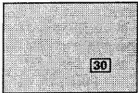

CAUTION: TO MAINTAIN THE LIFE OF THE LAMP, ONCE YOU HAVE TURNED IT ON, WAIT AT LEAST 5 MINUTES BEFORE TURNING IT OFF.
NOTE: TEMPERATURE WARNING INDICATOR flashes red, the projector will automatically turn off. Wait at least 5 minutes before turning the projector on.
If the TEMPERATURE WARNING INDICATOR continued to flash, follow the procedures below:
(1). Press POWER ON/OFF button to OFF.
(2). Check the air filter for dust accumulation.
(3). Remove dust with vacuum cleaner (See "AIR FILTER CARE AND CLEANING" section on page 53.)
(4). Press POWER ON/OFF button to ON.
If the TEMPERATURE WARNING INDICATOR still continues to flash, call your authorized dealer or service station.
TO TURN OFF THE PROJECTOR
Press the POWER ON/OFF button on the remote control unit or on the projector. The "Power off ?" appears on the screen. Press again the POWER ON/OFF button to turn OFF the projector. The LAMP POWER indicator will light bright and READY indicator will turn off. The cooling fans will operate for 1 minute after the projector is turned off. (During this "cooling down" period, the projector cannot be turned on.) The READY indicator will light green again and the projector may be turned on by pressing the POWER ON/OFF button. To power down completely, turn the MAIN ON/OFF switch (located on the side of the projector) to the OFF position.
Power off?
DIRECT OPERATION
MODE SELECT
Press the MODE button on the projector or the COMPUTER and VIDEO button on the remote control unit to select Computer 1, Computer 2, Video 1 or Video 2 Input. The "Computer 1", "Computer 2", "Video 1" or "Video 2" display will appear on the screen for a few seconds.
MODE button
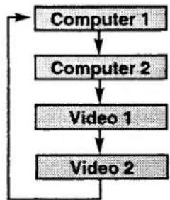
flowchart
graph TD
    A["Computer 1"] --> B["Computer 2"]
    B --> C["Video 1"]
    C --> D["Video 2"]
    D --> A
COMPUTER button
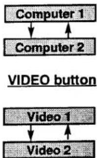
flowchart
graph TD
    A["Computer 1"] --> B["Computer 2"]
    C["VIDEO button"] --> D["Video 1"]
    E["Video 2"] --> F["Video 1"]
SOUND VOLUME ADJUSTMENT
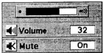
Press the VOLUME buttons on the projector or on the remote control unit to adjust the volume. The volume display will be displayed on the screen for a few seconds.
Pressing volume (+) will increase volume and increase the number on the screen.
Pressing volume (-) will decrease volume and decrease the number on the screen.
SOUND MUTE FUNCTION
Pressing the MUTE button on the remote control unit will mute audio. Press the MUTE button again to restore audio to its previous level. The mute display will be displayed on the screen for a few seconds.
LOM ADJUSTMENT
Use Top control and Wireless/Wired remote control unit.
Press the ZOOM (▲) or (▼) button to obtain your desired picture size. For a larger picture, press (▲) and for a smaller picture, press (▼).
Use Wireless remote control unit.
Press the ZOOM button and press POINT UP/DOWN button(s) to obtain your desired picture size. The Zoom display will be displayed on the screen for a few seconds. For a larger picture, press (UP) and for a smaller picture, press (DOWN).
FOCUS ADJUSTMENT
Use Top control and Wireless/Wired remote control unit.
Press the FOCUS (▲) or (▼) button for a sharper, crisper picture.
Use Wireless remote control unit.
Press the FOCUS button and press POINT UP/DOWN button(s) to obtain a sharper, crisper picture. The Focus display will be displayed on the screen for a few seconds.
LENS SHIFT FUNCTION
Use Top control and Wireless/Wired remote control unit.
Press the LENS SHIFT (▲) or (▼) button to obtain your desired screen position.
"ise Wireless remote control unit.
ess the LENS SHIFT button and press POINT UP/DOWN button(s) to obtain your desired screen position. The Lens shift display will be displayed on the screen for a few seconds.
Zoom
Focus
Lens shift
DIGITAL ZOOM FUNCTION
Press the D. ZOOM button on the wireless remote control unit. The "D.zoom" and the magnifying-glass icon is displayed to indicate Digital zoom mode. Digital zoom mode can be adjust the image size or pan the image.
To expand the image size, press SELECT (REAR CLICK) button. The image is magnified by degrees (Expand function).
To compress the image size, press FRONT CLICK button. The size of image is reduced by degrees (Compress function).
To pan the image, press POINT UP/DOWN/LEFT/RIGHT (POINTING PAD) button(s). The image move to the direction indicated (Panning function)
See the page 49 for more detail.
NORMAL PICTURE FUNCTION
The normal picture image level is factory preset on the projector and can be restored anytime by pressing the NORMAL button on the projector or on the remote control unit. The "Normal" display will be displayed on the screen for a few seconds.

FREEZE PICTURE FUNCTION
Press the FREEZE/NO SHOW button on the remote control unit, and the picture will remain on-screen. This function is cancelled when the FREEZE/NO SHOW button is pressed again or any other button is pressed.
NOTE: Your computer or video equipment is not affected by this function, and will continue to run.
NO SHOW FUNCTION
Press the FREEZE/NO SHOW button (on the remote control unit) is twice. The screen will change into black image and the "NO SHOW" is displayed on the screen for a few seconds.
This function is cancelled when the FREEZE/NO SHOW button is pressed again or any other function button is pressed.
P-TIMER FUNCTION
Press the P-TIMER button on the remote control unit. The timer display "00:00" appears on the screen and the timer starts to count the time (00:00 to 59:59). Press again the P-TIMER button to stop the timer. Then press the P-TIMER button to cancel the P-TIMER function.
AUTO IMAGE FUNCTION
Press the AUTO IMAGE button on the projector or on the remote control unit. The item(s) indicated "ON" in the AUTO IMAGE FUNCTION are adjusted automatically.
If all the items in AUTO IMAGE FUNCTION are "OFF", AUTO IMAGE SETTING display appears. If you wish to operate the AUTO IMAGE FUNCTION, perform the steps 3 - 9 of "AUTO IMAGE FUNCTION" section on page 42.
CURSOR FUNCTION
Press the CURSOR button on the wireless remote control unit. The CURSOR is displayed on the screen. Press POINT UP/DOWN/LEFT/RIGHT (POINTING PAD) button(s) to control CURSOR. The CURSOR is moved according to the direction you are pressing. Press CURSOR button again, and CURSOR disappears.
natural_image
Simple black arrow pointing right inside a rectangular frame (no text or symbols)MENU OPERATION
in MENU OPERATION mode, you can adjust the projector. You can use the TOP CONTROL OF THE PROJECTOR or the REMOTE CONTROL UNIT.
TOP CONTROL OF
THE PROJECTOR
WIRELESS/WIRED REMOTE CONTROL UNIT
POINT UP BUTTON
WIRELESS REMOTE CONTROL UNIT
POINT(UP/DOWN/LEFT/RIGHT)BUTTON
Pressing the button upward, downward, leftward or rightward.
MODE SELECT
You can select a mode from MAIN MENU display among computer 1, computer 2, video 1, video 2.
- Press the MENU BUTTON and the MAIN MENU DISPLAY dialog box will appear.
- Press the POINT LEFT/RIGHT BUTTON(s) to select Computer or Video and press the SELECT (REAR CLICK) BUTTON. Another dialog box MODE DISPLAY will appear.
- Press the POINT DOWN BUTTON and a red arrow will appear.
- Move the arrow to the mode you want (computer 1, computer 2, video 1 or video 2) to use by pressing the POINT UP/DOWN BUTTON(s) and then press the SELECT (REAR CLICK) BUTTON.
MAIN MENU DISPLAY

MAIN MENU DISPLAY

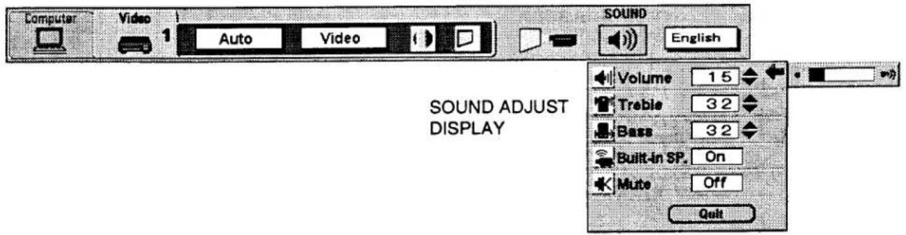
SOUND ADJUSTMENT
You can adjust the sound volume, treble, bass levels and Built-in SP., Sound Mute ON/OFF switch in the MENU display.
- Press the MENU BUTTON and the MAIN MENU DISPLAY dialog box will appear.
- Press the POINT LEFT/RIGHT BUTTON(s) to select SOUND and press the SELECT (REAR CLICK) BUTTON. Another dialog box SOUND ADJUST DISPLAY will appear.
- Press the POINT DOWN BUTTON and a red arrow will appear.
- Move the arrow to an item that you want to adjust by pressing the POINT UP/DOWN BUTTON(s).
- To increase the sound volume, treble and bass, point the arrow to ▲ and then press the SELECT (REAR CLICK) BUTTON. To decrease the sound volume, treble and bass, point the arrow to ▼ and then press the SELECT (REAR CLICK) BUTTON.
- To disconnect the built-in speaker, point the arrow to Built-in SP. and then press the SELECT (REAR CLICK) BUTTON. The display is changed Off and Internal speaker is disconnected.
- To mute the sound, point the arrow to Mute and then press the SELECT (REAR CLICK) BUTTON. The display is changed On and mute the sound.
- To quit the MENU, point to Quit and then press the SELECT (REAR CLICK) BUTTON.
MAIN MENU DISPLAY
LANGUAGE ADJUSTMENT
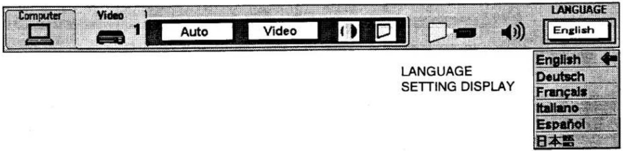
A language in the MENU display can be selected among English, German, French, Italian, Spanish and Japanese.
- Press the MENU BUTTON and the MAIN MENU DISPLAY dialog box will appear.
- Press the POINT LEFT/RIGHT BUTTON(s) to select LANGUAGE and press the SELECT (REAR CLICK) BUTTON. Another dialog box LANGUAGE SETTING DISPLAY will appear.
- Press the POINT DOWN BUTTON and a red arrow will appear.
- Move the arrow to the language you want to use by pressing the POINT UP/DOWN BUTTON(s) and then press the SELECT (REAR CLICK) BUTTON.
MAIN MENU DISPLAY
COLOR SYSTEM SELECT
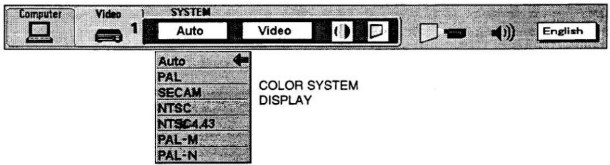
. is projector is compatible with the six major broadcast video standards: PAL, SECAM, NTSC, NTSC 4.43, PAL-M and PAL-N (COLOR SYSTEMs). When the color system is set to "Auto position", this projector can detect one of 4 systems (PAL, SECAM, NTSC or NTSC 4.43) automatically. However, if the video signal is not strong enough to detect the video format, the projector may not reproduce the proper video image. In case this happens, this projector allows you to choose a specific broadcast signal format.
- Connect the video equipment to the PROJECTOR and turn the projector on first.
- Set MODE SELECT to "VIDEO MODE".
- Press the MENU BUTTON and the MAIN MENU DISPLAY dialog box will appear.
- Press the POINT DOWN BUTTON and a red arrow will appear.
-
The setting changed remains effective until the MAIN ON/OFF switch is turned off.
-
Press the POINT LEFT/RIGHT BUTTON(s) to select SYSTEM and press the SELECT (REAR CLICK) BUTTON. Another dialog box COLOR SYSTEM DISPLAY will appear. The current COLOR SYSTEM is displayed in the system window.
-
To change the current COLOR SYSTEM, press the POINT UP/DOWN BUTTON(s) to move the arrow to a desirable system and then press the SELECT (REAR CLICK) BUTTON.
MAIN MENU DISPLAY
VIDEO SOURCE SELECT
- Connect the video equipment to the PROJECTOR and turn the projector on first.
- Set MODE SELECT to "VIDEO MODE".
- Press the MENU BUTTON and the MAIN MENU DISPLAY dialog box will appear.
- Press the POINT LEFT/RIGHT BUTTON(s) to select VIDEO SOURCE and press the SELECT (REAR CLICK) BUTTON. Another dialog box VIDEO SOURCE DISPLAY will appear. The current VIDEO SOURCE is displayed in the window.
- Press the POINT DOWN BUTTON and a red arrow will appear.
- To change the current VIDEO SOURCE, press the POINT UP/DOWN BUTTON(s) to move the arrow to a desirable video source and then press the SELECT (REAR CLICK) BUTTON.
- The setting changed remains effective until the MAIN ON/OFF switch is turned off.
MAIN MENU DISPLAY

PICTURE IMAGE ADGUSTMENT
Picture adjustments have been preset at the factory. If you want to change the setting, operate the projector as follows.
- Press MENU BUTTON and the MAIN MENU DISPLAY dialog box will appear.
- Press the POINT LEFT/RIGHT BUTTON(s) to select IMAGE and press the SELECT (REAR CLICK) BUTTON. Another dialog box IMAGE ADJUST DISPLAY will appear. This shows the current picture settings.
-
In this dialog box, you can adjust the settings by increasing or decreasing the levels shown as numbers. The items and the range of the levels that you can adjust are summarized in the table below.
-
Press the POINT DOWN BUTTON and a red arrow will appear.
-
Move the arrow to an item that you want to adjust by pressing the POINT UP/DOWN BUTTON(s).
-
To increase the level, point the arrow to ▲ and then press the SELECT (REAR CLICK) BUTTON. To decrease the level, point the arrow to ▼ and then press the SELECT (REAR CLICK) BUTTON.
-
You may want to store the settings in the memory so that you can recall them later. To store the settings, move the arrow to Stored and then press the SELECT (REAR CLICK) BUTTON. When you have stored the settings, "OK?" is displayed for confirmation.
-
Move the arrow to Yes and then press the SELECT (REAR CLICK) BUTTON. The stored settings are memorized even if the MAIN ON/OFF is switched off.
-
To quit the MENU, move the arrow to Quit and then press the SELECT (REAR CLICK) BUTTON.
-
If you do not want to store the settings, move the arrow to Quit and then press the SELECT (REAR CLICK) BUTTON. The settings changed remains effective until the MAIN ON/OFF switch is turned off.
-
To recall the settings from the memory that you have stored, move the arrow to Reset and then press the SELECT (REAR CLICK) BUTTON. When you have reset the settings, "OK ?" is displayed for confirmation. Move the arrow to Yes and then press the SELECT (REAR CLICK) BUTTON. You can adjust the settings again if needed.
NOTE : "TINT" will be skipped in the PAL, SECAM, PAL-M and PAL-N mode.
MAIN MENU DISPLAY
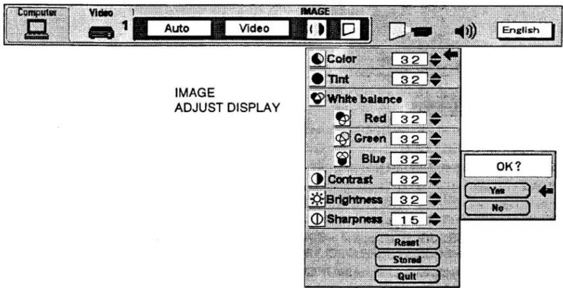
TABLE OF PICTURE IMAGE ADJUSTMENT
| COLOR | DECREASES | 0←→63 INCREASES |
| TINT | MORE PURPLE | 0←→63 MORE GREEN |
| WHITE BALANCE (R/G/B) | DECREASES | 0←→63 INCREASES |
| CONTRAST | LIGHTER | 0←→63 DEEPER |
| BRIGHTNESS | DARKER | 0←→63 BRIGHTER |
| SHARPNESS | SOFTER | 0←→31 SHARPER |
PICTURE SCREEN ADJUSTMENT
s projector has the Wide function, which enables you to view a wider video image.
WIDE function
This projector is able to project not only a normal video image (with 4 x 3 aspect ratio), but also a wider video image by compressing 4 x 3 image. This feature enable you to enjoy watching pictures like cinema images. You can switch either to WIDE or to REGULAR screen mode.
- Press the MENU BUTTON and the MAIN MENU DISPLAY dialog box will appear.
- Press the POINT LEFT/RIGHT BUTTON(s) to select SCREEN and press the SELECT (REAR CLICK) BUTTON.
Another dialog box SCREEN ADJUST DISPLAY will appear. - Press the POINT DOWN BUTTON and a red arrow will appear.
- To switch to "Wide" mode, move the arrow to Wide by pressing the POINT UP/DOWN BUTTON(s) and then press the SELECT (REAR CLICK) BUTTON.
- To switch to "Regular" mode, move the arrow to Regular by pressing the POINT UP/DOWN BUTTON(s) and then press the SELECT (REAR CLICK) BUTTON.
MAIN MENU DISPLAY

COMPUTER SYSTEM SELECT
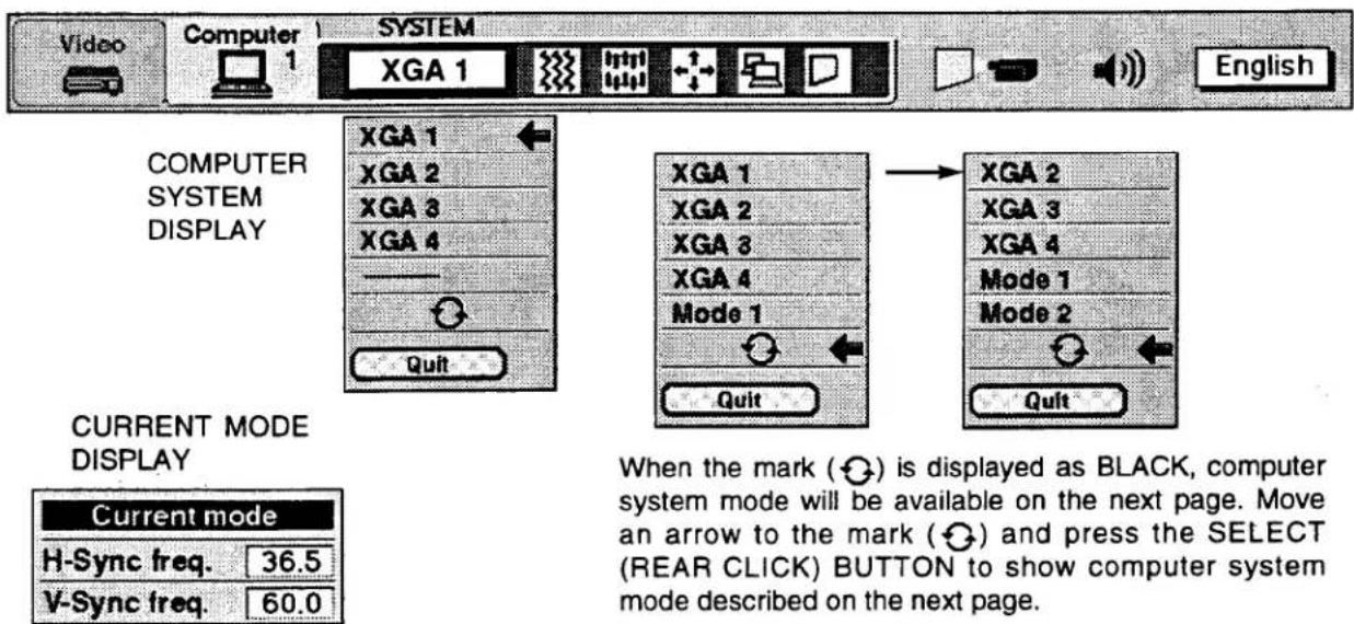
This projector is adjustable to different types of computer display signals based on VGA, SVGA, XGA, SXGA or UXGA (S "COMPATIBLE COMPUTER SPECIFICATIONS" on the next page). If you set MODE SELECT to "COMPUTER", the projector will automatically process the incoming signal and project the proper image without any special setting. Although this will work in most cases, you may be required to manually set the projector for some computer signals. If the computer image is not reproduced properly, try the following procedure and switch to the computer display mode that you want to use.
- Connect the COMPUTER to the PROJECTOR and turn the projector on first.
- Set MODE SELECT to "COMPUTER MODE (1 or 2)". This shows the current display mode initially detected by the projector in the system window. And "Current mode" display appears.
NOTE: 1. If the projector cannot discriminate or detect the input signal from the computer, the "Go PC adj." display appears.
NOTE : 2. If no input signal from the computer, the "No signal" display appears.
NOTE : 3. If the incoming signal is digital, the "D-VGA", "D-SVGA", "D-XGA", D-SXGA" or "D-UXGA" display appears.
-
Press the MENU BUTTON and the MAIN MENU DISPLAY dialog box will appear.
-
Press the POINT LEFT/RIGHT BUTTON(s) to select SYSTEM and press the SELECT (REAR CLICK) BUTTON. Another dialog box COMPUTER SYSTEM DISPLAY will appear.
-
Press the POINT DOWN BUTTON and a red arrow will appear.
-
If you want to change the current display mode, move the arrow by pressing the POINT UP/DOWN BUTTON(s) to select one of the modes.
-
Press the SELECT (REAR CLICK) BUTTON to change the display mode.
-
To quit the MENU, move the arrow to Quit and then press the SELECT (REAR CLICK) BUTTON.
MAIN MENU DISPLAY
PC ADJUSTMENT
This is a special function that may be used when a computer image is not reproduced properly. (See the pages 45 \~ 48 for more detail.)
COMPATIBLE COMPUTER SPECIFICATIONS
| ON-SCREEN DISPLAY | RESOLUTION | H-Freq. (kHz) | V-Freq. (Hz) |
| VGA1 | 640 x 480 | 31.47 | 59.88 |
| VGA2 | 720 x 400 | 31.47 | 70.09 |
| VGA3 | 640 x 400 | 31.47 | 70.09 |
| VGA4 | 640 x 480 | 37.86 | 74.38 |
| VGA5 | 640 x 480 | 37.86 | 72.81 |
| VGA6 | 640 x 480 | 37.50 | 75.00 |
| VGA7 | 640 x 480 | 43.269 | 85.00 |
| MAC LC13 | 640 x 480 | 34.97 | 66.60 |
| MAC13 | 640 x 480 | 35.00 | 66.67 |
| SVGA1 | 800 x 600 | 35.156 | 56.25 |
| SVGA2 | 800 x 600 | 37.88 | 60.32 |
| SVGA3 | 800 x 600 | 46.875 | 75.00 |
| SVGA4 | 800 x 600 | 53.674 | 85.06 |
| SVGA5 | 800 x 600 | 48.08 | 72.19 |
| SVGA6 | 800 x 600 | 37.90 | 61.03 |
| SVGA7 | 800 x 600 | 34.50 | 55.38 |
| VGA8 | 800 x 600 | 38.00 | 60.51 |
| SVGA9 | 800 x 600 | 38.60 | 60.31 |
| SVGA10 | 800 x 600 | 32.70 | 51.09 |
| SVGA11 | 800 x 600 | 38.00 | 60.51 |
| MAC16 | 832 x 624 | 49.72 | 74.55 |
| XGA1 | 1024 x 768 | 48.36 | 60.00 |
| XGA2 | 1024 x 768 | 68.677 | 84.997 |
| XGA3 | 1024 x 768 | 60.023 | 75.03 |
| XGA4 | 1024 x 768 | 56.47 | 70.07 |
| XGA5 | 1024 x 768 | 60.31 | 74.92 |
| XGA6 | 1024 x 768 | 48.50 | 60.02 |
| XGA7 | 1024 x 768 | 44.00 | 54.58 |
| XGA8 | 1024 x 768 | 63.48 | 79.35 |
| XGA9 | 1024 x 768 | 36.00 | 87.17 (Interlace) |
| XGA10 | 1024 x 768 | 62.04 | 77.07 |
| XGA11 | 1024 x 768 | 61.00 | 75.70 |
| XGA12 | 1024 x 768 | 35.522 | 86.96 (Interlace) |
| ON-SCREEN DISPLAY | RESOLUTION | H-Freq. (kHz) | V-Freq. (Hz) |
| XGA13 | 1024 x 768 | 46.90 | 58.20 |
| XGA14 | 1024 x 768 | 47.00 | 58.30 |
| XGA15 | 1024 x 768 | 58.03 | 72.00 |
| MAC19 | 1024 x 768 | 60.24 | 75.08 |
| SXGA1 | 1152 x 864 | 64.20 | 70.40 |
| SXGA2 | 1280 x 1024 | 62.50 | 58.60 |
| SXGA3 | 1280 x 1024 | 63.90 | 60.00 |
| SXGA4 | 1280 x 1024 | 63.34 | 59.98 |
| SXGA5 | 1280 x 1024 | 63.74 | 60.01 |
| SXGA6 | 1280 x 1024 | 71.69 | 67.19 |
| SXGA7 | 1280 x 1024 | 81.13 | 76.107 |
| SXGA8 | 1280 x 1024 | 63.98 | 60.02 |
| SXGA9 | 1280 x 1024 | 79.976 | 75.025 |
| SXGA10 | 1280 x 960 | 60.00 | 60.00 |
| SXGA11 | 1152 x 900 | 61.20 | 65.20 |
| SXGA12 | 1152 x 900 | 71.40 | 75.60 |
| SXGA13 | 1280 x 1024 | 50.00 | 86.00 (Interface) |
| SXGA14 | 1280 x 1024 | 50.00 | 94.00 (Interface) |
| SXGA15 | 1280 x 1024 | 63.37 | 60.01 |
| SXGA16 | 1280 x 1024 | 76.97 | 72.00 |
| SXGA17 | 1152 x 900 | 61.85 | 66.00 |
| SXGA18 | 1280 x 1024 | 46.43 | 86.70 (Interface) |
| SXGA19 | 1280 x 1024 | 63.79 | 60.18 |
| SXGA20 | 1280 x 1024 | 91.146 | 85.024 |
| MAC21 | 1152 x 870 | 68.68 | 75.06 |
| MAC | 1280 x 960 | 75.00 | 75.08 |
| MAC | 1280 x 1024 | 80.00 | 75.08 |
| UXGA1 | 1600 x 1200 | 75.00 | 60.00 |
| UXGA2 | 1600 x 1200 | 81.25 | 65.00 |
| UXGA3 | 1600 x 1200 | 87.50 | 70.00 |
| UXGA4 | 1600 x 1200 | 93.750 | 75.00 |
'fications are subject to change without notice.
NOTE: Basically this projector can accept the signal from all computers with the above mentioned V, H-Frequency and less than 200 MHz of Dot Clock.
AUTO IMAGE FUNCTION
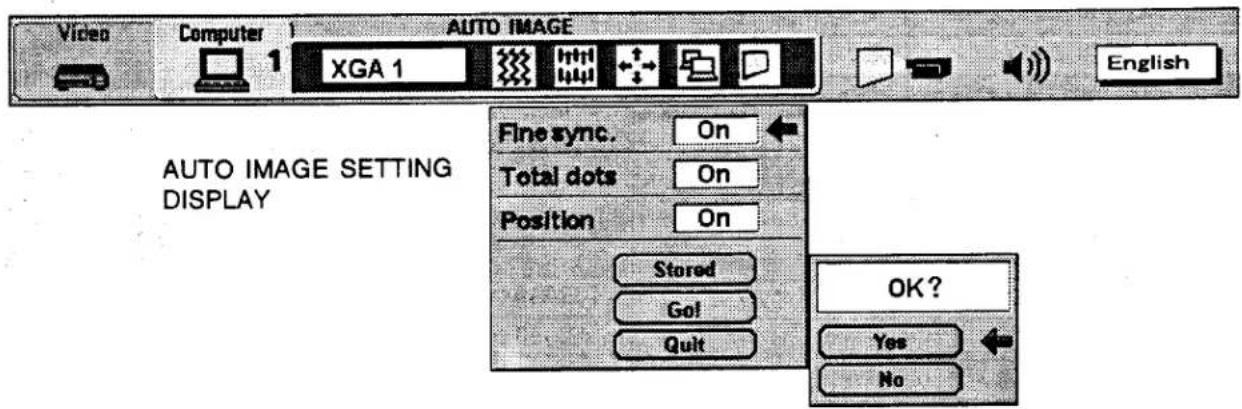
The Auto image function is provided to automatically adjust Fine sync., Total dots and Screen position for most computers.
NOTE: This auto image function will be skipped when the incoming signal is digital.
- Press the MENU BUTTON and the MAIN MENU DISPLAY dialog box will appear.
- Press the POINT LEFT/RIGHT BUTTON(s) to select AUTO IMAGE and press the SELECT (REAR CLICK) BUTTON. Another dialog box AUTO IMAGE SETTING DISPLAY will appear.
- Press the POINT DOWN BUTTON and a red arrow will appear.
- Move the arrow to an item(s) you want to adjust by pressing the POINT UP/DOWN BUTTON(s).
- Change the setting "On", press the SELECT (REAR CLICK) BUTTON.
- Move the arrow by pressing the POINT UP/DOWN BUTTON(s) to select "Go!" and then press the SELECT (REAR CLICK) BUTTON. The auto image function is started now. It will take about 10 seconds.
- To store the settings, move the arrow to Stored and then press the SELECT (REAR CLICK) BUTTON. When you have stored the settings, "OK?" is displayed for confirmation.
- Move the arrow to "Yes" and then press the SELECT (REAR CLICK) BUTTON. The stored settings are memorized even if the MAIN ON/OFF is switched off.
- To quit the MENU, point to Quit and then press the SELECT (REAR CLICK) BUTTON.
- This setting is temporarily effective until you turn off the projector or change the input signal.
NOTE: The fine sync., total dots and screen position of some computers may not be fully adjusted with the "Auto Image Function." In that case, use the "Picture Image" and/or "Picture Position" adjustments (see pages 43 \~ 44) to make fine-adjust them after the "Auto Image Function" is executed.
MAIN MENU DISPLAY
PICTURE IMAGE ADJUSTMENT
ure adjustments have been preset at the factory. If you want to change the setting, operate the projector as follows.
- Press the MENU BUTTON and the MAIN MENU DISPLAY dialog box will appear.
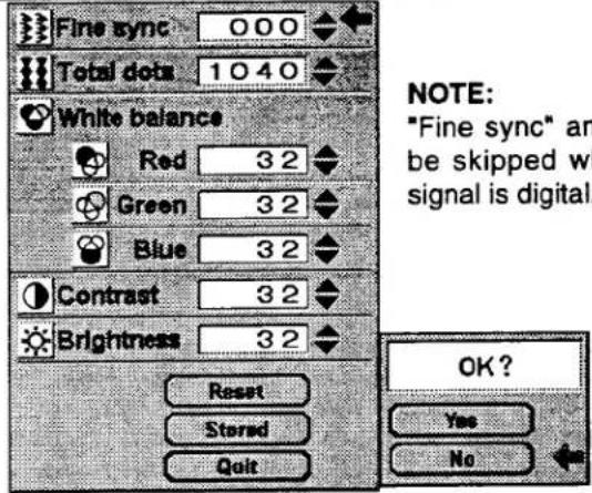
- Press the POINT LEFT/RIGHT BUTTON(s) to select IMAGE and press the SELECT (REAR CLICK) BUTTON. Another dialog box IMAGE ADJUST DISPLAY will appear. This shows the current picture settings.
-
In this dialog box, you can adjust the settings by increasing or decreasing the levels shown as numbers. The items and the range of the levels that you can adjust are summarized in the table below.
-
Press the POINT DOWN BUTTON and a red arrow will appear.
-
Move the arrow to an item that you want to adjust by pressing the POINT UP/DOWN BUTTON(s).
-
To increase the level, point the arrow to ▲ and then press the SELECT (REAR CLICK) BUTTON. To decrease the level, point the arrow to ▼ and then press the SELECT (REAR CLICK) BUTTON.
-
You may want to store the settings in the memory so that you can recall them later. To store the settings, move the arrow to Stored and then press the SELECT (REAR CLICK) BUTTON. When you have stored the settings, "OK?" is displayed for confirmation.
-
Move the arrow to Yes and then press the SELECT (REAR CLICK) BUTTON. The stored settings are memorized even if the MAIN ON/OFF is switched off.
-
To quit the MENU, move the arrow to Quit and then press the SELECT (REAR CLICK) BUTTON.
-
If you do not want to store the settings, move the arrow to Quit and then press the SELECT (REAR CLICK) BUTTON. The settings changed remains effective until the MAIN ON/OFF switch is turned off.
-
To recall the settings from the memory that you have stored, move the arrow to Reset and then press the SELECT (REAR CLICK) BUTTON. When you have reset the settings, "OK?" is displayed for confirmation. Move the arrow to Yes and then press the SELECT (REAR CLICK) BUTTON. You can adjust the settings again if needed.
MAIN MENU DISPLAY

IMAGE ADJUST DISPLAY
NOTE:
The projector may not reproduce a proper image for some UXGA signals.
Since UXGA (1600 x 1200) image is converted to SXGA (1280 x 1024) image by partial scan, some lines and dots of the image do not appear.
Some video noise of flicker on this compressed UXGA image cannot be eliminated even though you try to make a Fine sync adjustment.
NOTE:
"Fine sync" and "Total dots" will be skipped when the incoming signal is digital.
TABLE OF PICTURE IMAGE ADJUSTMENT
| FINE SYNC | Adjust the picture as necessary to eliminate flicker from the display. 0←→127 |
| TOTAL DOTS | The number of the total dots in one horizontal period. Adjust the number to match your PC image. |
| WHITE BALANCE (R/G/B) | DECREASE 0←→63 INCREASE |
| CONTRAST | LIGHTER 0←→63 DEEPER |
| BRIGHTNESS | DARKER 0←→63 BRIGHTER |
PICTURE POSITION ADJUSTMENT
- Press the MENU BUTTON and the MAIN MENU DISPLAY dialog box will appear.
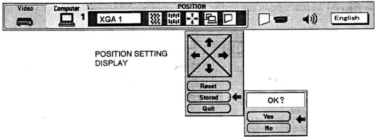
- Press the POINT LEFT/RIGHT BUTTON(s) to select POSITION and press the SELECT (REAR CLICK) BUTTON. Another dialog box POSITION SETTING DISPLAY will appear.
- Press the POINT DOWN BUTTON and a red arrow will appear.
- Move the arrow to a desirable direction (←, →, ↑ or ↓) by pressing the POINT LEFT/RIGHT/UP/DOWN BUTTON(s) and press the SELECT (REAR CLICK) BUTTON to a desirable picture position.
- You may want to store the settings to the memory so that you can recall them later. To store the settings, move the arrow to Stored and then press the SELECT (REAR CLICK) BUTTON. When you have stored the settings, "OK ?" is displayed for confirmation.
- Move the arrow to Yes and then press the SELECT (REAR CLICK) BUTTON. The stored settings are memorized even if the MAIN ON/OFF is switched off.
- To quit the MENU, move the arrow to Quit and then press the SELECT (REAR CLICK) BUTTON.
- If you do not want to store the settings, move the arrow to Quit and then press the SELECT (REAR CLICK) BUTTON. The settings changed remains effective until the MAIN ON/OFF switch is turned off.
- To recall the settings from the memory that you have stored, move the arrow to Reset and then press the SELECT (REAR CLICK) BUTTON. When you have reset the settings, "OK ?" is displayed for confirmation. Move the arrow to Yes and then press the SELECT (REAR CLICK) BUTTON. You can adjust the settings again if needed.
MAIN MENU DISPLAY
PC ADJUSTMENT
. .FE: This function will be skipped when the incoming signal is digital.
This projector can automatically detect most display signals from most personal computers currently distributed. However, some computers adopt a special signal format which is different from the standard one and the projector cannot detect it. If this happens, the projector cannot reproduce a proper image. And a flickering picture, a non-synchronized picture, a non-centered picture or a skewed picture may be projected instead.
For those non-standard formats, this projector is provided with PC ADJUST, enabling you to precisely adjust several parameters to match with the input signal format. The projector has eight independent memory areas where you can store the parameter you have set. This enables you to recall the setting for a specific computer when you need it.
- Press the MENU BUTTON and the MAIN MENU DISPLAY dialog box will appear.
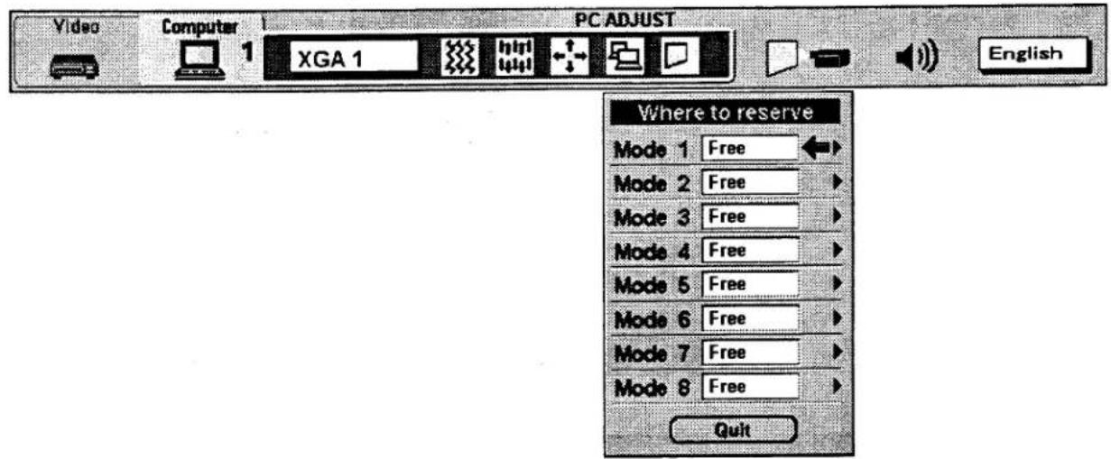
- Press the POINT LEFT/RIGHT BUTTON(s) to select PC ADJUST and press the SELECT (REAR CLICK) BUTTON. Another dialog box "Where to reserve" will appear.
- In this dialog box, you will select one of the memory areas from among "Mode 1" to "Mode 8". If parameters have been previously set and stored in the memory, the status "Stored" will appear on the corresponding row. If not, "Free" will appear.
- Press the POINT DOWN BUTTON and a red arrow will appear.
- Move the arrow to one of the "Modes" (Free position) where you want to store the parameters by pressing the POINT UP/DOWN BUTTON(s). Press the SELECT (REAR CLICK) BUTTON to select it.
NOTE: If "Stored" appears in all Modes, no new PC parameter data can be stored. In this case, clear the PC parameter data using Mode free Function.
MAIN MENU DISPLAY
- Another dialog box "PC ADJUSTMENT DISPLAY 1" will appear and the parameter data for the Mode you have selected is shown in this dialog box.
- The parameters will be filled with the data determined by the projector according to the present signal input.
- The function of the parameters and their values are summarized in the table as below.
- Move the arrow to an item that you want to adjust by pressing the POINT UP/DOWN BUTTON(s).
- To increase the level, point the arrow to ▲ and then press the SELECT (REAR CLICK) BUTTON. To decrease the level, point the arrow to ▼ and then press the SELECT (REAR CLICK) BUTTON.
- If you want to store the settings in the memory, move the arrow to Stored and press the SELECT (REAR CLICK) BUTTON. When you have stored the settings, "OK ?" is displayed for confirmation. Move the arrow to Yes and then press the SELECT (REAR CLICK) BUTTON.
- To recall the parameter data before setting, move the arrow to Reset and then press the SELECT (REAR CLICK) BUTTON. When you have reset the settings, "OK ?" is displayed for confirmation. Move the arrow to Yes and then press the SELECT (REAR CLICK) BUTTON. You can adjust the settings again if needed.
- To quit the MENU, move the arrow to Quit and then press the SELECT (REAR CLICK) BUTTON.
- If you quit the MENU without storing the settings in the memory, the parameter data you changed will not be kept.
- The stored settings are memorized even if the MAIN ON/OFF is switched off.
- Adjust the data such as a "Clamp", "Display area", "Horiz. scale" and "Vert. scale" if needed, move the arrow by pressing the POINT UP/DOWN BUTTON(s) to select (▼). Press the SELECT (REAR CLICK) BUTTON.
MAIN MENU DISPLAY
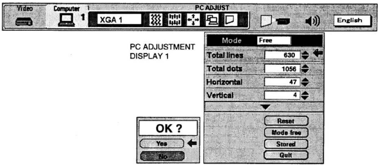
| ITEM | FUNCTION |
| TOTAL LINES | The number of the total vertical lines. Adjust the number to match your PC image. |
| TOTAL DOTS | The number of the total dots in one horizontal period. Adjust the number to match your PC image. |
| HORIZONTAL | Adjustment of the horizontal picture position. When the image is not centered on the screen, adjust this. |
| VERTICAL | Adjustment of the vertical picture position. When the image is not centered on the screen, adjust this. |
- Another dialog box "PC ADJUSTMENT DISPLAY 2" will appear and the parameter data for the Mode you have selected is shown in this dialog box.
Move the arrow to an item that you want to adjust by pressing the POINT UP/DOWN BUTTON(s).
- To increase the level, point the arrow to ▲ and then press the SELECT (REAR CLICK) BUTTON. To decrease the level, point the arrow to ▼ and then press the SELECT (REAR CLICK) BUTTON.
- If you want to store the settings in the memory, move the arrow to Stored and press the SELECT (REAR CLICK) BUTTON. When you have stored the settings, "OK ?" is displayed for confirmation. Move the arrow to Yes and then press the SELECT (REAR CLICK) BUTTON.
- To recall the parameter data before setting, move the arrow to Reset and then press the SELECT (REAR CLICK) BUTTON. When you have reset the settings, "OK ?" is displayed for confirmation. Move the arrow to Yes and then press the SELECT (REAR CLICK) BUTTON. You can adjust the settings again if needed.
- To quit the MENU, move the arrow to Quit and then press the SELECT (REAR CLICK) BUTTON.
- If you quit the MENU without storing the settings in the memory, the parameter data you changed will not be kept.
- The stored settings are memorized even if the MAIN ON/OFF is switched off.
MAIN MENU DISPLAY
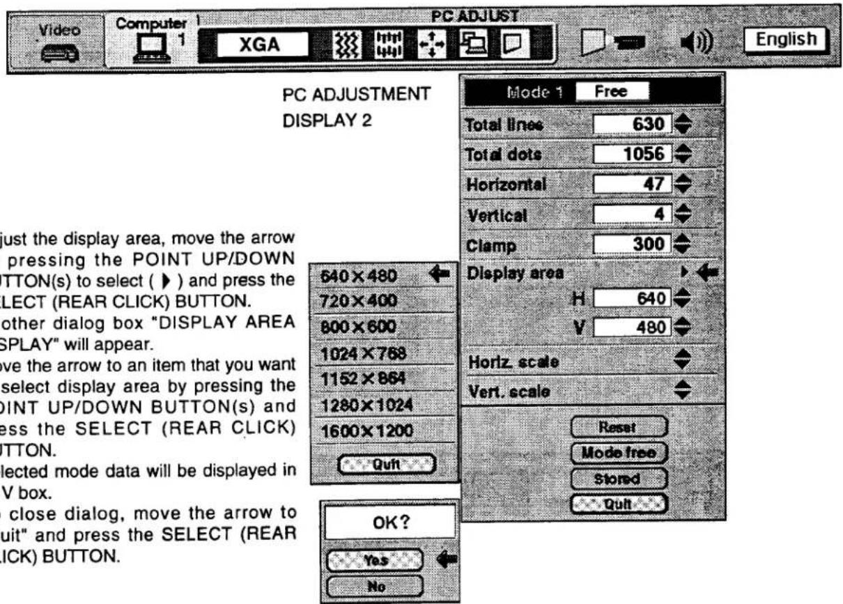
| ITEM | FUNCTION |
| CLAMP | Adjustment of the clamp level. When the image has a dark bar, try this adjustment. |
| DISPLAY AREA | Adjustment the display area to match your PC. |
| HORIZ. SCALE | Expanding or compressing level for the horizontal direction. |
| VERT. SCALE | Expanding or compressing level for the vertical direction. |
MODE FREE
The Mode free function is provided to confirm or clear the parameter data produced by PC ADJUST.
- Press the MENU BUTTON and the MAIN MENU DISPLAY dialog box will appear.
- Press the POINT LEFT/RIGHT BUTTON(s) to select PC ADJUST and press the SELECT (REAR CLICK) BUTTON. Another dialog box "Where to reserve" will appear.
- Press the POINT DOWN BUTTON and a red arrow will appear.
- Move the arrow to one of the "Modes" (Stored position) that you want to confirm by pressing the POINT UP/DOWN BUTTON(s). Press the SELECT (REAR CLICK) BUTTON. Another dialog box "PC ADJUSTMENT DISPLAY" will appear.
- To quit the MENU, point to Quit and then press the SELECT (REAR CLICK) BUTTON.
- To modify the parameter data, perform the steps 9 \~ 24 of PC ADJUSTMENT SECTION.
- To clear the parameter data, move the arrow by pressing the POINT UP/DOWN BUTTON(s) to select Mode free. Press the SELECT (REAR CLICK) BUTTON. "OK?" is displayed for confirmation.
- Move the arrow to Yes and then press the SELECT (REAR CLICK) BUTTON to clear the parameter data.
- To quit the MENU, move the arrow to Quit and then press the SELECT (REAR CLICK) BUTTON.
MAIN MENU DISPLAY
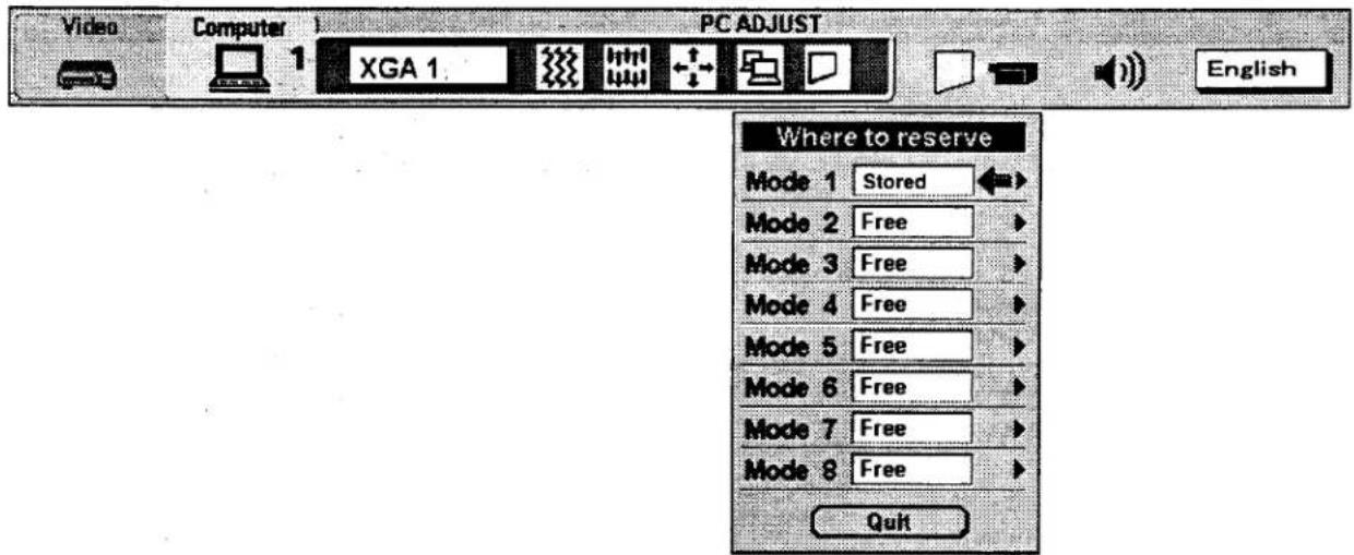
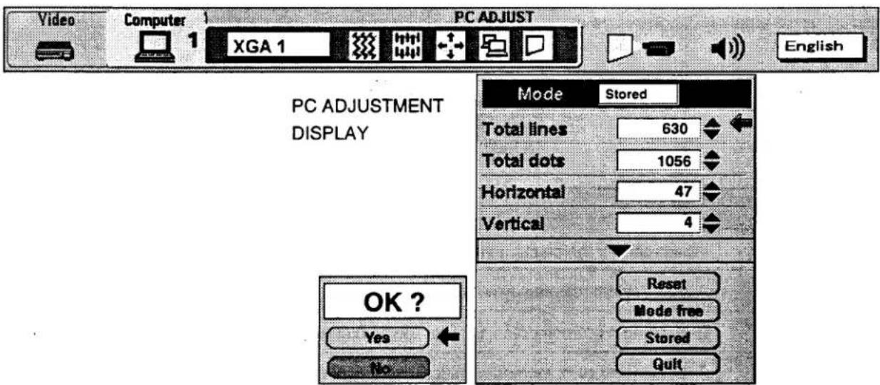
PICTURE SCREEN ADJUSTMENT
is projector can adjust the image size and pan the image with PICTURE SCREEN ADJUSTMENT.
- Press MENU BUTTON and MAIN MENU DISPLAY dialog box will appear.
- Press POINT LEFT/RIGHT BUTTON(s) to select SCREEN and press the SELECT (REAR CLICK) BUTTON. Another dialog box SCREEN ADJUST DISPLAY will appear.
- Press POINT DOWN BUTTON and a red arrow will appear.
MAIN MENU DISPLAY

- To adjust the image size or pan the image, move the arrow to Digital zoom by pressing POINT UP/DOWN BUTTON(s) and then press SELECT (REAR CLICK) BUTTON. MAIN MENU DISPLAY and SCREEN ADJUST DISPLAY will disappear. The "D.zoom" and the magnifying-glass icon is displayed to indicate Digital zoom mode.
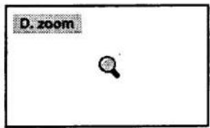
- Move the magnifying-glass icon by pressing the POINT UP/DOWN/LEFT/RIGHT (POINTING PAD) BUTTON(s).
- To expand the image, press SELECT (REAR CLICK) BUTTON. The image is magnified by degrees (Expand function). To compress the image size, press FRONT CLICK button on the remote control. The size of image is reduced by degrees (Compress function).
- To pan the image, press POINT UP/DOWN/LEFT/RIGHT (POINTING PAD) BUTTON(s) and move the magnifying-glass icon.
-
To cancel the Digital Zoom mode, press other buttons (Except NORMAL and CURSOR BUTTONS).
-
Press the NORMAL BUTTON in Digital zoom mode, the image size changed to the screen size (1280 x 1024).
-
Press the CURSOR BUTTON in Digital zoom mode, the magnifying-glass icon is disappears on the screen. However, the Digital Zoom mode is held.
-
To turn the image size to true size (1280 x 1024 in SXGA or UXGA, 1024 x 768 in XGA, 800 x 600 in SVGA and 640 x 480 in VGA), move the arrow to True by pressing POINT UP/DOWN BUTTON(s) and then press SELECT (REAR CLICK) BUTTON. The image size is turned to the true size.
-
This projector cannot display in the resolution more than 1600 × 1200 . If your computer's screen resolution is higher than 1600 × 1200 , reset the resolution to the lower.
● The image data of VGA (640 x 480), SVGA (800 x 600), XGA (1024 x 768) or UXGA (1600 x 1200) is modified to fit the screen size in the initial mode. - When the original image size is larger than the screen size (1280 x 1024), this projector becomes Digital Zoom mode automatically.
- The maximum size in expand mode is 4 times as large as the original screen size. (When original image size is smaller than the screen size (1280 x 1024).
● The maximum size in expand mode is 3.5 times as large as the screen size (1280 x 1024). (When original image size is larger than the screen size (1280 x 1024). - The minimum size in compress mode is the screen size (1280 x 1024) in SXGA or UXGA mode, 1024 x 768 in XGA mode, 800 x 600 in SVGA mode or 640 x 480 in VGA mode. Panning function can work only when the image is expanded.
● The normal "Panning Operation" may not function properly if the computer system prepared with the "PC Adjust" is used.
This projector has other functions setting: Blue back, Display, Reverse T/B, Reverse R/L, Split wipe, Power management, USB, Remote control and Lamp age.
BLUE BACK (On or Off)
When this function is in the "On" position, the projector will project a blue image without video noise on the screen when the video source is unplugged or turned off.
DISPLAY (On or Off)
When this function is in the "On" position, on-screen displays always appear when adjustments are made. Although these on-screen displays are very helpful, these may spoil the view if adjustments are made during presentations. To avoid this, you can keep back certain displays by switching this function "Off". The followings are the displays that you can hide.
● Wait Display
● Mute Display
● Normal Display
● Mode Display
● Zoom/Focus/Lens shift Display
● No show Display
● Volume Display
● D.Zoom Display
REVERSE T/B (On or Off)
When this function is in the "On" position, the top/bottom picture reverse.
REVERSE L/R (On or Off)
When this function is in the "On" position, the left/right picture reverse capability lets you project onto a rear projection screen.
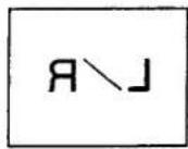
SPLIT WIPE (On or Off)
Turn SPLIT WIPE function On in the SETTING menu. The picture will change into next one by sliding black image side ways when the input source is changed.
Change the input source by MODE button. The picture is replaced by black image from side ways to the center, and the next one appears from the center to side ways like drawing the black curtains.
POWER MANAGEMENT (On or Off)
Power management will be turn the projector Lamp off when the input signal is interrupted (Picture is not displayed) over 5 minutes. This aims at saving power and Lamp life. The Lamp is automatically turned on when the signal is input.
To activate this function, turn the "Power management" in the SETTING menu "On".
USB (Mouse or Control)
This Projector is designed for connecting with USB Port of the computer or peripheral equipment that is to be standard.
When this function is in the "☐" (Mouse) position, you control the pointer of the computer used the projector's wireless remote control unit.
When this function is in the " [icon] " (Control) position, you control the projector by computer.
NOTE: Before you control the projector by computer, install USB driver (optionally sold parts) and set up the computer following instruction in the USB driver package. Contact your authorized dealer.
PEMOTE CONTROL CODE CHANGE (Mode 1 or Mode 2)
This projector can be operated with two different code, one is factory-set normal code (MODE 1) and the other one is extended code (MODE 2).
This is used to prevent the remote control operation mixture (jam) when two projector and several remote control video equipments are system-up and used together.
When you change the code MODE 2, you must change both projector and Remote Control Unit.
To change Projector code;
Set REMOTE CONTROL in SETTING menu (below figure) to "MODE 2".
To change Remote Control Unit code;
Press both "MENU" and "NORMAL" button on the Remote Control Unit for over 10 seconds.
After code changed, make sure the Remote Control operation is functioning properly. To go back to normal code (MODE 1), take same operation above.
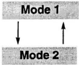
flowchart
graph TD
    A["Mode 1"] --> B["Mode 2"]
    B --> A
Setting the Blue back, Display, Reverse T/B, Reverse R/L, Split wipe, Power management, USB and Remote control
- Press the MENU BUTTON and the MAIN MENU DISPLAY dialog box will appear.
- Press the POINT LEFT/RIGHT BUTTON(s) to select SETTING and press the SELECT (REAR CLICK) BUTTON. Another dialog box SETTING DISPLAY will appear.
Press the POINT DOWN BUTTON and a red arrow will appear.
.ove the arrow to an item you want to set by pressing the POINT UP/DOWN BUTTON(s).
- If you want to change the setting, press the SELECT (REAR CLICK) BUTTON.
- To quit the MENU, point to Quit and then press the SELECT (REAR CLICK) BUTTON.
- The settings are memorized even if the MAIN ON/OFF is switched off.
MAIN MENU DISPLAY
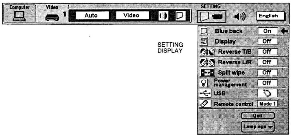
LAMP AGE
The Lamp age function is designed to reset the lamp replacement monitor timer. When replacing the lamp, reset the la replacement monitor timer by using this function.
NOTE: Do not reset the LAMP REPLACEMENT MONITOR TIMER, except after the lamp is replaced.
- Press the MENU BUTTON and the MAIN MENU DISPLAY dialog box will appear.
- Press the POINT LEFT/RIGHT BUTTON(s) to select SETTING and press the SELECT (REAR CLICK) BUTTON. Another dialog box SETTING DISPLAY will appear.
- Press the POINT DOWN BUTTON and a red arrow will appear.
- Move the arrow by pressing the POINT UP/DOWN BUTTON(s) to select Lamp age and then press the SELECT (REAR CLICK) BUTTON. When you reset the lamp replace monitor, "lamp replace monitor reset?" is displayed for confirmation.
- Move the arrow to Yes and then press the SELECT (REAR CLICK) BUTTON, "OK?" is displayed for confirmation. Move the arrow to Yes and then press the SELECT (REAR CLICK) BUTTON, the lamp replace monitor is reset.
- Move the arrow to No and then press the SELECT (REAR CLICK) BUTTON. The lamp replace monitor is not reset.
- To quit the MENU, move the arrow to Quit and then press the SELECT (REAR CLICK) BUTTON.
MAIN MENU DISPLAY
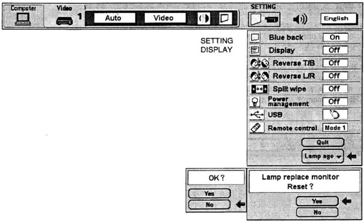
MEINTENANCE
TEMPERATURE WARNING INDICATOR
The TEMPERATURE WARNING INDICATOR flashes red when the internal temperature of the projector exceeds the normal temperature.
'possible causes for the temperature warning may be :
. Ventilation slots of the projector are blocked. In such an event, reposition the projector so that ventilation slots are not obstructed.
Air filter is clogged with dust particles. Remove dust from the air filter by following instructions in the Air Filter Care and Cleaning section above.
. If temperature warning indicator remains on after performing the checks listed above, cooling fan/internal circuits may be malfunctioning. Request service from an authorized dealer or service station.
AIR FILTER CARE AND CLEANING
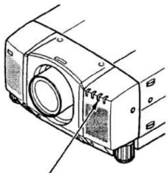
natural_image
Technical line drawing of a mechanical device with no visible text or symbolsTEMPERATURE WARNING INDICATOR
The removable air filter prevents dust from accumulating on the surface of the projection lens and projection mirror. Should the air filter become clogged with dust particles, it will reduce the cooling fan's effectiveness and may result in internal heat build up and reduce the life of the projector.
o clean the air filter, follow the cleaning procedures below: n the POWER ON/OFF button OFF.
-
Remove the air filter cover.
-
Remove the air filter and sponge from the filter cover.
Clean the air filter with a vacuum cleaner.
- Replace the air filter and sponge. Make sure that air filter cover is fully inserted.

Do not clean with water. Doing so may damage the air filter. Do not operate the projector with air filter removed.
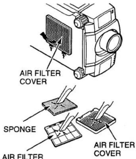
RECOMMENDATION
O ENJOY PICTURE IMAGE, USE THE PROJECTOR IN THE CLEAN ENVIRONMENT. USAGE IN THE CLEAN ENVIRONMENT IS RECOMMENDED.
When used under the dusty or smoky conditions, dust may accumulate on the liquid crystal panel and lens inside it, and may resultantly be projected on the screen together with the picture.
When the above symptoms are noticed contact the place where your authorized dealer service station for the cleaning.
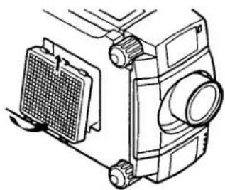
natural_image
Technical line drawing of a mechanical device with a grid component and adjustment knobs (no text or symbols)LAMP REPLACEMENT
WHEN THE PROJECTION LAMP OF THIS PROJECTOR DRAWS TO AN END, THE LAMP REPLACEMENT INDICATOR LIGHTS YELLOW AND THE WARNING MESSAGE "LAMP REPLACEMENT" APPEARS AS THE RIGHT FIGURE. WHEN THE WARNING MESSAGE IS DISPLAYED, THE PROJECTION LAMP SHOULD BE REPLACED.
To terminate the warning message.
Replace the Projection Lamp and reset the LAMP REPLACEMENT MONITOR TIMER (See "LAMP AGE" section on page 52.), and the warning message is terminated.
To erase the warning message in a moment.
To erase the warning message for a moment, move the arrow to "YES" by pressing the POINT UP/DOWN BUTTON(s) and then press the SELECT (REAR CLICK) BUTTON. This procedure is temporary measure, and the warning massage appears again when the projector is turned on next time.
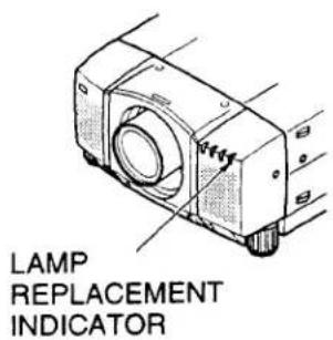
LAMP REPLACEMENT
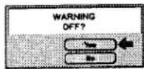

● For continued safety, replace with a lamp assembly of the same type.
- Allow the projector to cool for at least 45 minutes before you open the lamp cover. The inside of the projector can become very hot.
- Do not drop the lamp module or touch the glass bulb! The glass can shatter and cause injury.
Follow these steps to replace the lamp assembly.
- Turn off the projector and allow the projector to cool thoroughly.
- Disconnect the AC cord from the projector.
- Remove 2 screws with a screwdriver and remove the lamp cover.
- Remove 2 screws with a screwdriver and pull out the lamp assembly by grasping the handle.
- Replace the lamp assembly.
- Tighten 4 screws to secure the lamp cover to the lamp assembly.
- Connect the detachable AC cord to the projector.
- Reset the lamp replacement monitor timer.
(See "LAMP AGE" section on page 52.)
NOTE: Do not reset the LAMP REPLACEMENT MONITOR TIMER, except after the lamp is replaced.
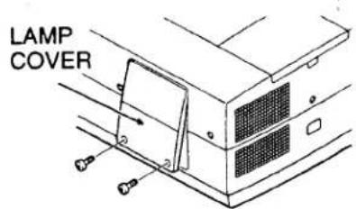
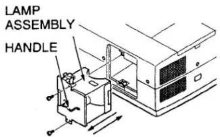
CLEANING THE LENS
Now these steps to clean the projection lens:
.. Apply a non-abrasive camera lens cleaner to a soft, dry cleaning cloth.
Avoid using an excessive amount of cleaner.
Abrasive cleaners, solvents or other harsh chemicals might scratch the lens.
... Lightly wipe the cleaning cloth over the lens.
- When you don't use the projector, replace the lens cover.
TROUBLESHOOTING
Before calling your dealer or service station for assistance, check the matters below once again.
- Make sure you have connected the projector to your equipment as described in section "CONNECTING THE PROJECTOR" on pages 14 \~ 21.
- Check cable connections. Verify that all computer, video and power cords are properly connected.
- Verify that power is switched on.
If the projector still does not display an image, re-start the computer.
If the image still does not display, unplug the projector from the computer and check the computer monitor's display. The problem may be with your graphics controller rather than with the projector. (When you reconnect the projector, remember to turn the computer and monitor off before you power up the projector. Power the equipment back up in order of: Projector and computer)
5. If the problem still exists, check the following chart.
| Problem: | Try these Solutions: |
| No power. | Plug the projector into an AC outlet.Turn the MAIN ON/OFF switch to ON.Press the POWER ON/OFF switch to ON.Be sure the READY INDICATOR light is ON.Wait one minute after the projector is turned OFF before turning the projector back on.NOTE: After pressing the POWER ON/OFF button to OFF. The projector functions as indicated.The LAMP POWER indicator will light and the READY indicator will turn off.After one minute, the READY indicator will light green again and the projector may be turned on by pressing the POWER ON/OFF button.Check temperature warning indicator. If the indicator flashes red, the projector cannot be turned on.(See "BASIC OPERATION" section on page 32).Check the projection lamp.Replace the lamp cover. (Check the interlock switch inside of the lapm cover.) |
| Image is out of focus. | Adjust the focus.Make sure the projection screen is at least 4.9' (1.5 m) from the projector.Check the projection lens to see if it needs cleaning.NOTE: Moving the projector from a cool temperature location to a warm temperature location may result in moisture condensation on the lens. In such an event, leave the projector OFF and wait until condensation disappears. |
| Picture is T/B inverted. | Check Reverse T/B feature.(See "OTHER FUNCTION SETTING" section on pages 50 ~ 51). |
| Picture is L/R Reversed. | Check Reverse L/R feature.(See "OTHER FUNCTION SETTING" section on pages 50 ~ 51). |
| Some displays are not seen during the operation. | Check Display feature.(See "OTHER FUNCTION SETTING" section on pages 50 ~ 51). |
| No sound. | ● Check audio cable connection from audio input source.● Adjust audio source.● Press the VOLUME (+) button.● Press the MUTE button. |
| Remote control unit doesn't work. | ● Check the batteries.● Make sure nothing is blocking between the remote control sensor and remote control unit.● Make sure you are not too far from the projector when using the remote control unit. {Maximum operate range 16.4' (5 m)}.● Check the transmitted signal mode from the remote control unit.(See "OTHER FUNCTION SETTING" section on pages 50 ~ 51). |
| Wireless mouse function does not work. | ● Check the cable connection between the projector and the computer.● Check the mouse setting on your computer.● Turn on the projector before you turn on the computer. |
SERVICE
WARNING: High voltages are used to operate this projector. Do not attempt to open the cabinet.
You can often correct operating problems yourself. If the projector fails to work properly, see "TROUBLESHOOTING" section on pages 55-56. To correct the failure, try the "Solutions".
Sanyo Services is easily obtained. If after following all operating instructions, you find that service is necessary, contact the SFS Corporation in Los Angeles, or the store where you purchased the unit.
Give the model number and explain the difficulty. We will advise you how to obtain service.
TECHNICAL SPECIFICATIONS
| Projector Type | Multi-media Projector |
| Dimensions (W x H x D) | 15.4" (390 mm) x 9.2" (234 mm) x 22.9" (582 mm) |
| Net Weight | 39.2 lbs (17.8 kg) |
| LCD Panel System | 1.8" TFT Active Matrix type x 3 panels |
| Number of Pixels | 3,932,160 {1,310,720 (1,280 x 1,024) x 3} |
| Color System | 6 color system (PAL, SECAM, NTSC, NTSC4.43, PAL-M and PAL-N) |
| Scanning Frequency | H-sync. 15 ~ 100 KHz, V-sync. 50 ~ 100 Hz |
| Projection Image Size (Diagonal) | Adjustable from 40" to 600" |
| Horizontal Resolution | 800 TV lines |
| Projection Lens | F2.0 ~ 2.3 lens with f=75.7 mm ~ 97.5 mm Motor zoom and focus |
| Motorized Lens Shift | ± 760 mm on 100" screen |
| Throw Distance | 4.9' (1.5 m) ~ 80.7' (24.6 m) |
| Projection Lamp | 400 watt type |
| AV Input Jacks | BNC Type {Video/Y, C/Cb (B-Y), Cr (R-Y)} x 2 sets,RCA Type (Audio R and L) x 2 sets and DIN 4 pin (S-Video) x 2 sets |
| Video Monitor Output Jack | BNC Type {Video/Y, C/Cb (B-Y),Cr (R-Y)} x 1 setand DIN 4 pin (S-Video) x 1 set |
| o Monitor Output Jacks | RCA Type (R and L) x 1 set |
| Computer Input 1 Jack | MDR 20-pin Terminal (Digital), HDB 15-pin Terminal (Analog),Multi-pole 12-pin (Control port) and USB port |
| Computer Input 2 Jack | BNC Type (R, G, B, H and V), Multi-pole 12-pin (Control port) and USB port |
| Computer Audio Input Jack | RCA Type (R and L) x 2 sets |
| Computer Output Jack | HDB 15-pin Terminal |
| Computer Audio Output Jack | RCA Type (R and L) x 1 set |
| Other Jack | Wired Remote Jack and Serial port (DB 9) |
| Built-in Speaker | INT. SP. Stereo (R and L), 3 watt RMS (T.H.D.10%) |
| Image Elevation Adjustment | Up to 4° |
| Voltage | 100 ~ 120 V AC, 50/60 Hz |
| Power Consumption | 7.2 A (Max. Ampere) |
| Operating Temperature | 5°C ~ 35°C |
| Storage Temperature | -10°C ~ 60°C |
| Remote Control Transmitters | Wireless Remote Control with Laser Beam (Class II Laser)Max. Output 1mW/Wave Length 660 ± 20nm, batteries (2) AA type. |
| Wireless/Wired Remote Control, batteries (2) AA type. |

This symbol on the nameplate means the product is Listed by Underwriters Laboratories Inc. It is designed and manufactured to meet rigid U.L. safety standards against risk of fire, casualty and electrical hazards.
This page left intentionally blank.
- INTRODUCTION
- COMPATIBILITY
- IMAGE RESOLUTION
- AUTOMATIC MULTISCANNING SYSTEM
- SCREEN MODE
- MULTILANGUAGE
- UNPACKING THE PROJECTOR
- TRADEMARKS
- NAME OF EACH PART OF THE PROJECTOR
- FRONT OF THE PROJECTOR
- REAR OF THE PROJECTOR
- EXHAUST VENT
- CAUTION HOT AIR!
- BOTTOM OF THE PROJECTOR
- SETTING-UP THE PROJECTOR
- POSITIONING:
- ROOM LIGHT
- ADJUSTABLE FEET
- MOVE THE PROJECTED IMAGE POSITION
- VENTILATION
- MOVING THE PROJECTOR
- CAUTION IN CARRYING OR TRANSPORTING THE PROJECTOR
- POWER REQUIREMENTS
- TERMINAL OF THE PROJECTOR
- SIDE OF THE PROJECTOR (CONNECT THE COMPUTER)
- CONNECTING THE COMPUTER
- CONNECTING TO THE COMPUTER INPUT 1 TERMINAL (ANALOG HDB 15-PIN)
- CONNECTING TO THE COMPUTER INPUT 1 TERMINAL (DIGITAL MDR 20-PIN)
- CONNECTING TO THE COMPUTER INPUT 2 JACKS (BNC x 5)
- CONNECTING TO THE COMPUTER AUDIO INPUT JACKS (1 and 2)
- CONNECTING TO THE MULTI-POLE 12-PIN (CONTROL PORT) CONNECTORS (1 and 2,
- CONNECTING TO THE MONITOR OUTPUT TERMINAL (ANALOG HDB 15-PIN)
- Pin No./Signal
- CONNECTING TO THE AUDIO MONITOR OUTPUT (VARIABLE) JACKS
- CONNECTING TO THE SERIAL PORT (DB 9-PIN) TERMINAL
- CONNECTING TO THE USB PORT CONNECTORS (1 and 2)
- CONNECTING AN IBM-COMPATIBLE DESKTOP COMPUTER DIGITAL INPUT CONNECTION)
- NOTE:
- CONNECTING AN IBM-COMPATIBLE LAPTOP COMPUTER
- CONNECTING AN IBM-COMPATIBLE LAPTOP COMPUTER IGITAL INPUT CONNECTION)
- CONNECTING A MACINTOSH POWERBOOK COMPUTER
- CONNECTING THE VIDEO EQUIPMENT
- CONNECTING TO THE VIDEO INPUT JACKS (1 and 2) BNC TYPE x 3
- CONNECTING S-VHS VIDEO INPUT JACKS (1 and 2)
- CONNECTING TO THE AUDIO INPUT JACKS (1 and 2)
- CONNECTING TO THE VIDEO MONITOR OUTPUT JACKS (BNC TYPE x 3)
- CONNECTING TO THE S-VHS VIDEO MONITOR OUTPUT JACK
- CONNECTING TO THE AUDIO MONITOR OUTPUT JACKS
- LASER POINTER button
- COMPUTER SELECT BUTTON
- VIDEO SELECT BUTTON
- POWER ON/OFF BUTTON
- VOLUME BUTTONS
- ZOOM BUTTON
- P-TIMER BUTTON
- FOCUS BUTTON
- FREEZE/NO SHOW BUTTON
- SOUND MUTE BUTTON
- LENS SHIFT BUTTON
- CURSOR BUTTON
- AUTO IMAGE BUTTON
- MENU BUTTON
- NORMAL BUTTON
- When in use as a remote for the projector
- When in use as a wireless mouse
- LASER BUTTON
- FRONT CLICK BUTTON
- DIGITAL ZOOM BUTTON
- SELECT (REAR CLICK) BUTTON
- When in use as a remote for the projector.
- Remote Control Battery Installation
- Remove the battery compartment lid.
- Slide the batteries into the compartment.
- Replace the compartment lid.
- Using the Remote Control Unit
- WIRELESS/WIRED REMOTE CONTROL UNIT
- WIRED REMOTE JACK
- COMPUTER SELECT BUTTON
- VIDEO SELECT BUTTON
- POWER ON/OFF BUTTON
- VOLUME BUTTONS
- ZOOM BUTTONS
- FOCUS BUTTONS
- SOUND MUTE BUTTON
- LENS SHIFT BUTTONS
- AUTO IMAGE BUTTON
- MENU BUTTON
- FREEZE/NO SHOW BUTTON
- SELECT BUTTON
- DIGITAL ZOOM BUTTON
- NORMAL BUTTON
- Using the Remote Control Unit (wireless)
- Using the Remote Control Unit (wired)
- CONTROL THE PROJECTOR
- TURNING ON/OFF THE PROJECTOR
- TO TURN ON THE PROJECTOR
- TO TURN OFF THE PROJECTOR
- DIRECT OPERATION
- MODE SELECT
- SOUND VOLUME ADJUSTMENT
- SOUND MUTE FUNCTION
- LOM ADJUSTMENT
- FOCUS ADJUSTMENT
- LENS SHIFT FUNCTION
- DIGITAL ZOOM FUNCTION
- NORMAL PICTURE FUNCTION
- FREEZE PICTURE FUNCTION
- NO SHOW FUNCTION
- P-TIMER FUNCTION
- AUTO IMAGE FUNCTION
- CURSOR FUNCTION
- MENU OPERATION
- SOUND ADJUSTMENT
- LANGUAGE ADJUSTMENT
- COLOR SYSTEM SELECT
- VIDEO SOURCE SELECT
- PICTURE IMAGE ADGUSTMENT
- PICTURE SCREEN ADJUSTMENT
- WIDE function
- COMPUTER SYSTEM SELECT
- PC ADJUSTMENT
- PICTURE IMAGE ADJUSTMENT
- PICTURE POSITION ADJUSTMENT
- MODE FREE
- BLUE BACK (On or Off)
- DISPLAY (On or Off)
- REVERSE T/B (On or Off)
- REVERSE L/R (On or Off)
- SPLIT WIPE (On or Off)
- POWER MANAGEMENT (On or Off)
- USB (Mouse or Control)
- PEMOTE CONTROL CODE CHANGE (Mode 1 or Mode 2)
- To change Projector code;
- To change Remote Control Unit code;
- Setting the Blue back, Display, Reverse T/B, Reverse R/L, Split wipe, Power management, USB and Remote control
- LAMP AGE
- MEINTENANCE
- TEMPERATURE WARNING INDICATOR
- AIR FILTER CARE AND CLEANING
- RECOMMENDATION
- LAMP REPLACEMENT
- To terminate the warning message.
- To erase the warning message in a moment.
- CLEANING THE LENS
- TROUBLESHOOTING
- SERVICE
Brand : SANYO
Model : PLC-EF10N
Category : Projector