
ARTISTILE1PCFP - Cooker CAMBRIDGE - Free user manual and instructions
Find the device manual for free ARTISTILE1PCFP CAMBRIDGE in PDF.

| Product Type | Outdoor Gas Fire Pit Table |
| Brand | Cambridge |
| Model | ARTISTILE1PCFP |
| Fuel Type | Propane (LP) or Natural Gas with conversion kit |
| BTU Rating | 40,000 Btu/hr |
| Propane Regulator Pressure | 11 inches water column |
| Ignition Type | Push-button electronic ignition (requires 1 AAA battery) |
| Clearances | Sides: 24 in (61 cm), Top: 72 in (183 cm) from combustible surfaces |
| Material | Metal frame with decorative table top |
| Burner | Single burner with lava rock cover |
| Fuel Supply | 20 lb (9 kg) propane cylinder with Type 1 connection |
| Usage | Outdoor use only in well-ventilated area |
| Assembly Required | Yes, detailed instructions provided |
| Safety Features | Thermocouple safety device, automatic shutoff if flame goes out |
| Included Accessories | Lava rocks, regulator hose, bolts, tools, battery |
| Warranty | 90-day limited warranty on burner assembly, base, and top |
| Certification | CSA certified to ANSI Z21.97•CSA 2.41-2012 |
| Storage | Store indoors with cylinder disconnected; cylinder must be stored outdoors |
Frequently Asked Questions - ARTISTILE1PCFP CAMBRIDGE
User questions about ARTISTILE1PCFP CAMBRIDGE
0 question about this device. Answer the ones you know or ask your own.
Ask a new question about this device
Download the instructions for your Cooker in PDF format for free! Find your manual ARTISTILE1PCFP - CAMBRIDGE and take your electronic device back in hand. On this page are published all the documents necessary for the use of your device. ARTISTILE1PCFP by CAMBRIDGE.
USER MANUAL ARTISTILE1PCFP CAMBRIDGE
If you have any problems with this product (missing or damaged parts, assembly issues), please
DO NOT RETURN TO THE RETAILER/STORE
where you purchased the product. Call our Customer Service Hotline at:
1-800-416-3511
Between 9:00 AM and 5:00 PM Eastern Time, Monday through Friday
Or visit our website at: www.agio-usa.com
To expedite any future warranty claims, retain the instruction sheet, warranty card, and receipt for future use. you are encouraged to register your purchase on our website at www.agio-usa.com
For additional online video support on assembly, troubleshooting, and care and maintenance of your outdoor furniture, please visit our website at: www.agio-usa.com/support
ASSEMBLY INSTRUCTIONS

natural_image
Line drawing of a square table with ornate lattice and circular top (no text or symbols)
CSA Model 99000

ARL00100
Installer: Leave these instructions with consumer.
Consumer: Keep these instructions for future reference.
TANGER
If you smell gas:
- Shut off gas to the appliance.
- Extinguish any open flame.
- If odor continues, keep away from the appliance and immediately call your gas supplier or fire department.
WARNING
Do not store or use gasoline or other flammable vapors and liquids in the vicinity of this or any other appliance.
An LP-cylinder not connected for use shall not be stored in the vicinity of this or any other appliance.
WARNING:
Improper installation, adjustment alteration, service or maintenance can cause injury or property damage. Read the installation, operating and maintenance instructions thoroughly before installing or servicing this equipment.
WARNING: For Outdoor Use Only
FOR USE WITH 20LB (9KG) PROPANE CYLINDER WITH TYPE 1 CONNECTION OR FOR USE WITH NATURAL GAS AFTER CONVERSION KIT IS INSTALLED (MUST BE PROFESSIONALLY INSTALLED) ALSO THE LP REGULATOR MUST BE SUPPLIED BY THE MANUFACTURER.
| △DANGER | CARBON MONOXIDE HAZARD |
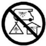 | This appliance can produce carbon monoxide which has no odor.Using it in an enclosed space can kill you.Never use this appliance in an enclosed space such as a camper, tent, car or home. |

Questions, Problems, Missing Parts? Before returning to your retailer, call our customer service department in the US and Canada at 1-800-416-3511, Monday-Friday, 9 a.m.-5 p.m. Eastern Time.
WARNING:
USE FACTORY APPROVED REPLACEMENT PARTS AND ACCESSORIES ONLY. USE OF UNAPPROVED PART OR ACCESSORIES CAN VOID THE WARRANTY ON THIS PRODUCT AND RESULT IN AHAZARDOUS CONDITION. PLEASE CONTACT US FOR INFORMATION REGARDING REPLACEMENT HOSES, THERMOCOUPLES, ELECTRODES, IGNITION MODULES, LAVAROCKS, LOG GS, FIRE ICE, ETC.
TABLE OF CONTENTS
Important Safety Information 3
Important About Propane 4
Specification 4
Parts Identification List 5-6
Installation 7-11
Batteries 11
Lighting Instructions 12
Maintenance 12-13
Troubleshooting Guide 13
Warranty 14
IMPORTANT SAFETY INFORMATION
The installation must conform with local codes or, in the absence of local codes, with the National Fuel Gas Code, ANSI Z223.1/NFPA 54; International Fuel Gas Code.; Natural Gas and Propane Installation Code, CSA B149.1; or Propane Storage and Handling Code, B149.2, as applicable.
The appliance must be isolated from the gas supply piping system by closing its equipment shutoff valve during any pressure testing of the gas supply system at test pressure equal to or less than 1/2 psi (3.5kPa).
The appliance area must be kept clear and free from combustible materials, gasoline and other flammable vapors and liquids.
Do not use this appliance if any part has been under water. Immediately call a qualified service technician to inspect the appliance and to replace any part of the control system and any gas control which has been under water.
Children and adults should be alerted to the hazards of high surface temperatures and kept at a safe distance to avoid burns or clothing ignition.
Young children should be carefully supervised when they are anywhere near the appliance.
Clothing or other flammable material should not be hung from the appliance, or placed on or near the appliance.
Any screen or guard removed for servicing an appliance must be replaced prior to operating the appliance.
Installation and repair should be done by a qualified service person. The appliance should be inspected before use and at least annually by a professional service person. More frequent cleaning may be required as necessary. It is imperative that the control compartments, burners and circulating air passageways of the appliance be kept clean.
Do NOT burn solid fuels in this gas fireplace.
CAUTION: The propane gas pressure regulator provided with this appliance must be used. This regulator is set for an outlet pressure of 11 inches water column.
This outdoor gas appliance is not intended to be installed in or on recreational vehicles and/or boats.
Before each use of this gas appliance, open the LP (Liquid Propane) Tank Drawer and inspect the LP Hose. If there is evidence of excessive abrasion or wear, or the hose is cut, it must be replaced prior to the gas appliance being put into operation. Use only the replacement hose assembly specified in this manual. Inspect the burner before each use of the appliance. The burner must be replaced prior to the appliance being put into operation if it is evident that the burner is damaged. Use only the burner listed in these instructions.
Keep the fuel supply hose away from any heated surfaces.
IMPORTANT SAFETY INFORMATION ABOUT
PROPANE (LP) GAS
A self contained LP-gas cylinder for use with this appliance must have a capacity of 20 lbs. and must be equipped with a Type 1 connector and an OPD (overfill protection device). See Figure 1.
The LP-gas supply cylinder to be used must be constructed and marked in accordance with the specification for LP-gas cylinders of the U.S. Department of Transportation (DOT) or the National Standard of Canada, CAN/CSA-B339, Cylinder, Sphere and Tubes for the Transportation of Dangerous Goods.
● The cylinder supply system must be arranged for vapor withdrawal.
● The cylinder used must include a collar to protect the cylinder valve.
● This appliance shall be used only outdoors in a well-ventilated space and shall not be used in a building, garage or any other enclosed space.
- When this appliance is not is use, the gas must be turned off at the supply cylinder.
● Storage of this appliance indoors is permissible only if the cylinder is disconnected and removed from the appliance.
- Cylinders must be stored outdoors in a well-ventilated area out of the reach of children. Disconnected cylinders must have threaded valve plugs tightly installed and must not be stored in a building, garage or any other enclosed areas.
CSA (Canadian Standards Association) certified to ANSI Z21.97•CSA 2.41-2012 “Outdoor Decorative Gas Appliances”

natural_image
Line drawing of a mechanical component with threaded fitting and attached parts (no text or symbols)F i g u r e 1
SPECIFICATIONS
| INPUT | 40,000 | Btu/hr |
| Propane Regulator Pressure 11 inches water column | ||
| Clearances to combustible surfaces | Sides 24in./61cm Top: 72 | in. / 183 cm |
PARTS IDENTIFICATION LIST
| PART | DESCRIPTION | PART# | |
| A |  | CONTROL KNOB FP1245 1 | |
| B |  | GAS VALVE FP0307 1 | |
| C |  | THERMOCOUPLE FP0004 | 1 |
| D |  | LP REGULATOR HOSE 65-FP-0181 | 1 |
| E |  | ELECTRODE 65-FP-0128 | 1 |
| F |  | ORIFICE ELBOW FP0310 1 | |
| G |  | IGNITION MODULE FP0006 1 | |
| H |  | PROPANE ORIFICE ZCF0021 | 1 |
| I |  | “AAA” BATTERY(1.5V) HW0705 | 1 |
| J |  | LAVA ROCK SET FP0002 1 | |
| K |  | FOOTCAP FC0559 | 4 |
| L |  | 1/4" X 15 MM BOLT HW0034 8 | |
| M |  | 1/4" X 20 MM BOLT HW0036 4 | |
| N |  | 1/4" X 40 MM BOLT HW0086 4 | |
| O |  | BOLT COVER HW0105 18 | |
| P |  | ∅6.5 X 1.0 MM WASHER HW0004 | 14 |
| Q |  | ∅18X∅6.5 X1.5MM WASHER HW0103 | 4 |
| R |  | NUTS HW0717 | 2 |
| S |  | HEX BOLT DRIVER HW0006 1 | |
| T |  | HEX WRENCH HW0008 1 |
| U | 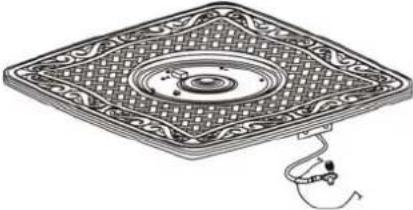 | FIREPIT TABLE TOP | 1 | ||
| V |  | BACK PANEL 1 | |||
| W | 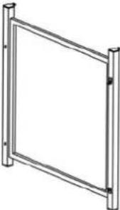 | LEFT SIDE PANEL | 1 | ||
| X |  | RIGHT SIDE PANEL | 1 | ||
| Y | 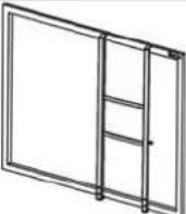 | DOOR PANEL 1 | |||
| Z | MIDDLE SUPPORT | 1 | |||
| AA | 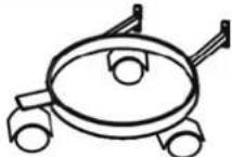 | LP SUPPORT 1 | |||
| BB | [2Y62] |  | BOTTOM/ TOP CONNECTOR | 1 | |
INSTALLATION
-
Identify parts packed in carton against the parts list. Remove all protective materials and set parts on a flat, non-abrasive surface.
-
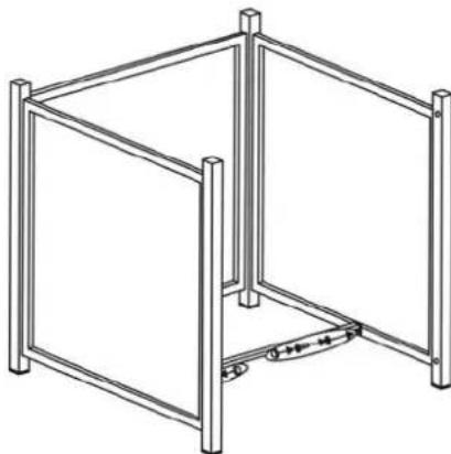
Attach the back panel to the side panels by using four 1/4"x40 mm bolts and washers as shown in Figure 2. Guide the bolts through the holes in back panel, into the pre-drilled holes in the side panels. Hand tighten only.

natural_image
Line drawing of a metal-framed storage unit with four oval-shaped compartments (no text or symbols)Figure 2
- Attach the middle support to the side panels by using four 1/4"x15 mm bolts and washers as shown in Figure 3. Guide the bolts through the holes in the middle support, into the pre-drilled holes in the side panels. Hand tighten only.
natural_image
Line drawing of a metal-framed cabinet or enclosure structure with vertical supports and a horizontal base (no text or symbols)Figure 3
- Attach the "L" connector to right side panel by using a 1/4"x15 mm bolt and washer as shown in Figure 4. Guide the bolt through the hole in the "L" connector, into the pre-drilled hole in the right side panel. Do not over tighten.
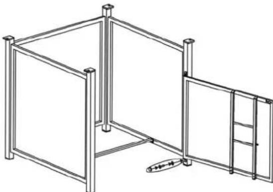
natural_image
Line drawing of a modular structure with vertical supports and a door, no text or symbols presentFigure 4
- Put the door onto the bottom connector, guide the pin in the bottom connector into the hole on the underside of the door. Then guide the pin on the top connector into the hole in the topside of the door, use a 1/4"x15 mm bolt and washer to attach this top connector to the right side panel as shown in Figure 5. Do not over tighten.

natural_image
Line drawing of a modular metal frame structure with vertical supports and a central door (no text or symbols)Figure 5
- With the help of another person, carefully place the table top onto the table base. After making any necessary adjustments to the alignment of the table top and the assembled base, use four 1/4"x20 mm bolts and washers as shown in Figure 6. Guide the bolts through the holes in the base, into the pre drilled holes in the table top. Do not tighten completely.

natural_image
Line drawing of a decorative table with ornate top and side supports (no text or symbols)Figure 6
- Attach the LP support the to door panel by using four 1/4"x15 mm bolts and washers as shown in Figure 7. Do not over tighten.

Figure 7
- Place gas tank onto the LP support as shown in Figure 8.
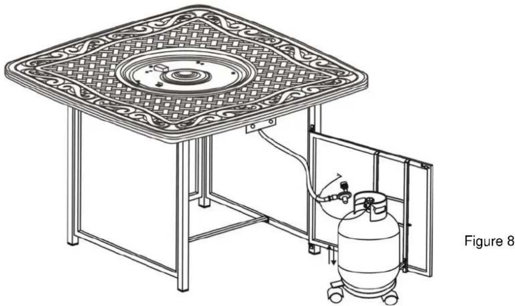
natural_image
Line drawing of a decorative table with ornate lattice patterns and a gas cylinder inside, labeled Figure 8 (no text or symbols on the diagram itself)- Attach the metal ring ( as shown in Figure 9) pre-fitted with gas hose which is connected to the table top , into the hole of the door panel, then use hex bolt driver to screw 1/4"x5mm nut , the gas tank has fixed as shown in Figure 9a. Connect the regulator as shown in Figure.10 Screw the black handle clock-wise to tighten. Turn the handle counter clock-wise to remove. The hose must point down. Check that the valve is turned all the way clockwise to the "OFF" position.
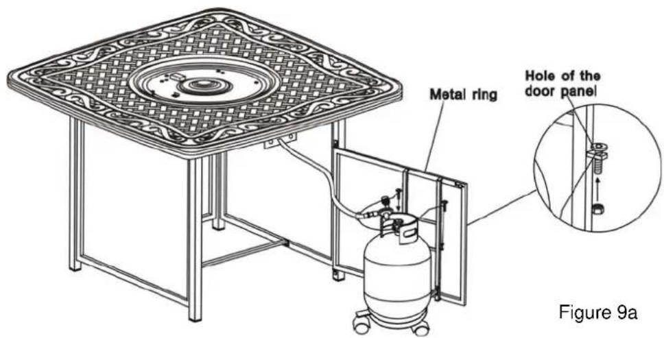
Figure 9
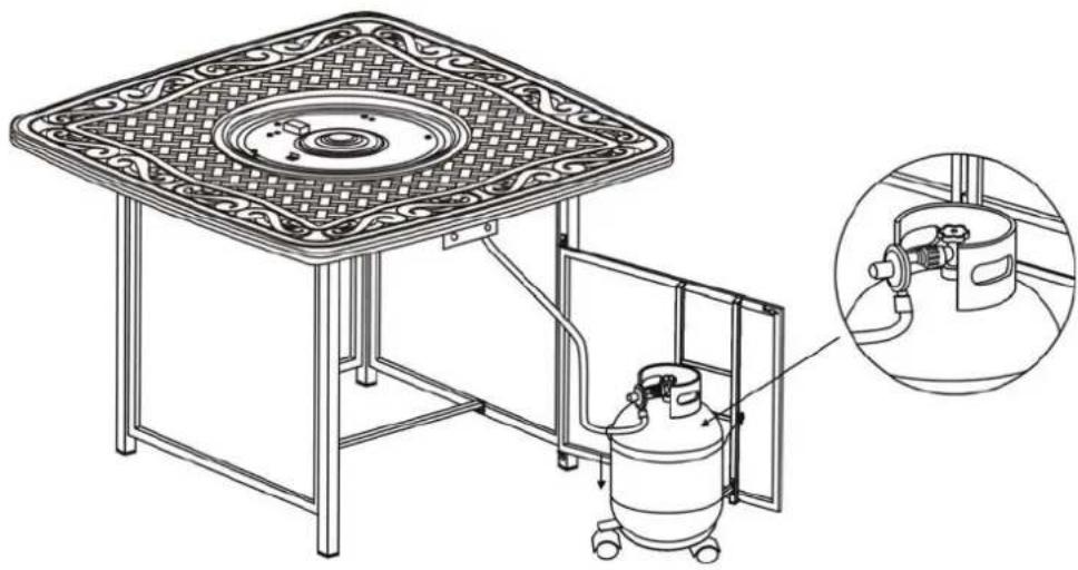
natural_image
Technical line drawing of a square table with ornate lattice patterns and a gas cylinder inside, plus an inset showing internal components (no text or symbols)Figure 10
- After making any necessary adjustments to the parts, use the hex bolt driver to tighten all bolts.
Note: each bolt must be tightened a few revolutions at a time.
Repeat until all bolts are tight. Do not over tighten. Over tightening may strip bolts. Cover all bolts with covers.
- Pour the lava rocks into the burner pan completely covering the burner. See Figure 11.
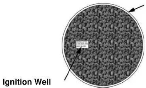
Figure 11
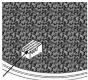
- Remove the cardboard cover from the ignition well as shown in Figure 12. Remove any lava rock or fire ice on top of ignition well.
natural_image
Isometric view of a small rectangular object on a textured surface, possibly a container or sensor array (no text or symbols visible)Cardboard Cover
Figure 12
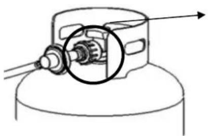
- Open the tank valve. Apply a solution of soapy water to the tank-regulator connection and to the valve-hose connection to check for leaks as shown in Figure 13. If soap bubbles continue to form, the connection has a leak. If a leak is found, close the tank valve and tighten all connections.
NOTE: NEVER USE A FLAME TO CHECK FOR LEAKS.
natural_image
Technical line drawing of a mechanical assembly with a gear and shaft (no text or symbols)Checking the tank-regulator for leaks
Figure 13
BATTERIES
Make sure the control knob is in the "OFF" position.
Unscrew the push button cap on the ignition module located on the control panel to access the battery compartment. The ignition module requires one Alkaline AAA size battery (1.5V). The negative (-) end goes in first. See Figure 14.
Dispose of battery safely. May explode or leak if charged or disposed of in fire. Make sure of the polarity. Mercury and cadmium free.
(1. 5 V.) AAA BATTERY COMPARTMENT INSTALL (-) SIDE FIRST
Warning: If these instructions are not followed exactly, a fire or explosion may result causing property damage, personal injury or loss of life.
- Make sure the control knob is in the "OFF" position. See Figure 15 Open the tank valve all the way.
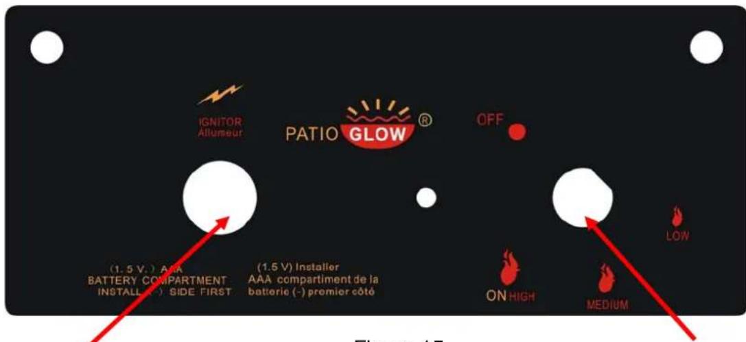
IGNITER BUTTON CONTROL KNOB
Figure 15
- Push in the igniter button. You will hear a slight clicking sound. With the igniter button pushed in, push and turn the control knob to the "ON" position. the fire should light within a few seconds. Once the flame is lit, release the igniter button and continue to hold the control knob in for 10 to 15 seconds. Release the control knob. The control knob should pop back out and then remain lit.
Note: If the fire does not light, turn the knob to the "OFF" position and wait five (5) minutes before trying again.
-
To turn down the flame, push the control knob in slightly and turn to Medium (medium or Low (small flame).
-
To shut down the fire pit, turn the control knob to the "OFF" position and turn off the tank valve.
MAINTENANCE
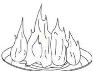
The flames should look like those in Figure 16. To clean the burner, use a soft brush after the burner has cooled completely. Never use a vacuum cleaner on the burner. It is recommended that the fire pit be stored indoors during the winter if it will be subjected to freezing temperatures. The LP cylinder must be disconnected and removed from the appliance before the appliance can be stored indoors.
natural_image
Line drawing of a flame-like object on a plate (no text or symbols)Figure 16
TROUBLESHOOTING GUIDE
| PROBLEM | CAUSE | REMEDY |
| Burner won't light | No Propane Gas at Burner | Check that gas tank valve is open. Turn control knob to “ON” and push control knob in. Make sure tank has propane gas. |
| No Spark at Electrode | Check that AAA battery is installed with negative (-) end first and has a charge. Check that the wire is connected to the ignition module. Check that the electrode is not cracked or broken. | |
| Lack of oxygen | Remove excess lava rocks or fire ices from around the ignition well. | |
| Burner won't stay lit after lighting | Thermocouple not in flame | Check that the tip of the thermocouple is even with the top of the ignition well.Remove any lava rocks from the ignition well. |
| Thermocouple connection at the main control valve is loose | Tighten the thermocouple nut at the back of the valve. | |
| No Lava Rocks on Burner | Cover the burner with lava rocks per the instructions |
90-DAYS LIMITED WARRANTY
What is Covered Under This Warranty?
The item you have purchased is warranted against defects in materials and workmanship for the following parts as outlined below only when unit is installed and operated in accordance with the instructions in this Owner's Manual and in compliance with local building and fire codes:
- Burner Assembly
- Firepit Base
- Firepit Top
How Do I Obtain Warranty Service?
To obtain warranty service, you must contact our customer service center within the relevant warranty period and provide us with a copy of your dated register receipt as proof of the purchase date. We reserve the right to request photographs and/or return of the defective item(s) and/or such other evidence relating to any claim as we shall reasonably require. Please call our customer service center at 1-800-416-3511 for additional warranty claim details and procedures.
What are the Limitations and Exclusions of this Warranty?
Warranty Limitations:
This warranty is subject to the limitation set forth above. In addition, this warranty is made to the original purchaser only and is effective only if items are purchased from one of our authorized dealers. This warranty is not transferable. For warranty replacements based on warranty claims submitted within ninety (90) days of purchase, we will not be responsible for charges associated with shipments outside continental North America at any time or for any reason.
Warranty Exclusions: This warranty is subjected to the exclusions set forth above. In addition, the following are excluded from coverage under this warranty: any item used for commercial, contract or any other non-residential purpose; clearance items, display models or items purchased "as is"; freight damage; items subject to misuse, abuse, neglect or lack of proper care or maintenance (including without limitation as provided in any "care and maintenance guide" or similar information we provide); normal wear and tear; damage caused by acts of nature, acts of force majeure, vandalism, fire or other causality, or improper assembly; hardware against corrosion or rusting; purchased or replacement parts; and all plastic parts. Also excluded are loss of use or time; inconvenience; money; travel; packaging; or incidental, special or consequential damages of any kind. Replacement of defective items or parts as provided herein shall constitute your sole and exclusive remedy for items which are not as warranted. In no event shall our responsibility exceed the purchase price of the item found to be other than as warranted. This warranty is the exclusive statement of your rights with respect to items you have purchased and supersedes any other express warranty or statement, written or oral, made in connection with the purchase and sale of such items. The term "item" when used herein in the singular refers to the specific piece found to be defective, and not to the entire set of which the item is a part.
Some states do not allow exclusion or limitation of incidental or consequential damage, so that limitation may not apply to you. This warranty gives you specific legal rights, and you may also have other rights that vary from state to state.

- DO NOT RETURN TO THE RETAILER/STORE
- ASSEMBLY INSTRUCTIONS
- TANGER
- WARNING
- WARNING:
- WARNING: For Outdoor Use Only
- TABLE OF CONTENTS
- IMPORTANT SAFETY INFORMATION
- IMPORTANT SAFETY INFORMATION ABOUT
- PROPANE (LP) GAS
- SPECIFICATIONS
- INSTALLATION
- BATTERIES
- MAINTENANCE
- 90-DAYS LIMITED WARRANTY
- What is Covered Under This Warranty?
- How Do I Obtain Warranty Service?
- What are the Limitations and Exclusions of this Warranty?
- Warranty Limitations:
Brand : CAMBRIDGE
Model : ARTISTILE1PCFP
Category : Cooker