SHL-989XT - Blood pressure monitor HealthyLine - Free user manual and instructions
Find the device manual for free SHL-989XT HealthyLine in PDF.

User questions about SHL-989XT HealthyLine
0 question about this device. Answer the ones you know or ask your own.
Ask a new question about this device
Download the instructions for your Blood pressure monitor in PDF format for free! Find your manual SHL-989XT - HealthyLine and take your electronic device back in hand. On this page are published all the documents necessary for the use of your device. SHL-989XT by HealthyLine.
USER MANUAL SHL-989XT HealthyLine
natural_image
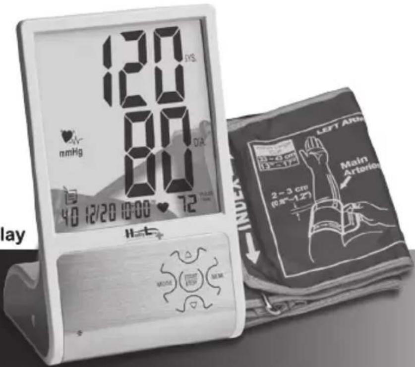
Abstract 3D spiral shape with gradient shading, no text or symbols presentxcrystal™
Innovative See-through Display

SOLUȚII PENTRU O SĂNĂTATE PERFECTĂ
CUPRINS
Atentionari 02
natural_image
Top-down schematic of a device layout with no visible text or symbols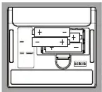
natural_image
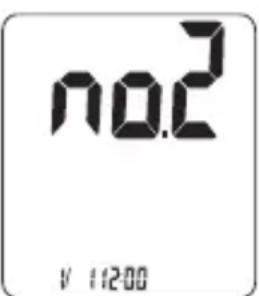
Diagram of a battery pack with multiple compartments and polarity indicators (no text or labels)Atentie!
natural_image
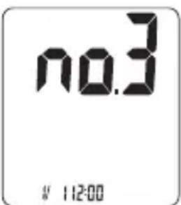
Line drawing of a person using a blood pressure monitor (no text or symbols present)MĂSURAREA TENSIUNII
NOTĂ!
NOTĂ!
Importer: S.C. Deck Computers Int. S.R.L.
Consumator:
This blood pressure monitor complies with the EC Directive and bears the CE mark "CE0197". This blood pressure monitor also complies with mainly following standards (included but not limited):
Safety standard:
EN 60601-1 Medical electrical equipment part 1: General requirements for safety
EMC standard:
EN 60601-1-2 Medical electrical equipment part 1-2: General requirements for safety- Collateral standard: Electromagnetic compatibility- Requirements and tests
Performance standards:
EN 1060-1 Non-invasive sphygmomanometers - General requirements
EN 1060-3 Non-invasive sphygmomanometers - Supplementary requirements for electromechanical blood pressure measuring systems.
EN 1060-4 Non-invasive sphygmomanometers - Test procedures to determine the overall system accuracy of automated non-invasive sphygmomanometers.
Important/Caution/Note!
Read the operating instructions.

Consult instructions thoroughly before use.
NOTE

Classification:
- Internally powered equipment
- BF type applied part
- IPX0
- Not suitable for use in presence of flammable anesthetic mixture with air or with Oxygen or nitrous oxide
- Continuous operation with short-time loading
To avoid inaccurate results caused by electromagnetic interference between electrical and electronic equipments, do not use the device near a mobile phone or microwave oven.
Discard the used product to the recycling collection point according to local regulations.
EC REP
EMERGO EUROPE
Molenstraat 15, 2513 BH, The Hague, The Netherlands
Phone: +31.70.345.8570
Fax: +31.70.346.7299
Appendix
| Guidance and manufacturer's declaration – electromagnetic emissions | ||
| The device is intended for use in the electromagnetic environments listed below, and should only be used in such environments: | ||
| Emissions test | Compliance | Electromagnetic environment – guidance |
| RF emissions CISPR 11 | Group 1 | The device uses RF energy only for its internal function. Therefore, its RF emissions are very low and are not likely to cause any interference in nearby electronic equipment. |
| RF emissions CISPR 11 | Class B | The device is suitable for use in all establishments, including domestic establishments and those directly connected to the public low-voltage power supply network that supplies buildings used for domestic purposes. |
| Harmonic emissions IEC 61000-3-2 | Class A | |
| Voltage fluctuations/flicker emissions IEC 61000-3-3 | Complies | |
| Guidance and manufacturer's declaration – electromagnetic immunity |
| The device is intended for use in the electromagnetic environments listed below, and should only be used in such environments: |
Appendix
| Immunity test | IEC 60601 test level | Compliance level | Electromagnetic environment –guidance |
| Electrostatic discharge (ESD)IEC 61000-4-2 | ±6 kV contact±8 kV air | ±6 kV contact±8 kV air | Floors should be wood, concrete or ceramic tile. If floors are covered with synthetic material, the relative humidity should be at least 30 %. |
| Electrical fast transient/burstIEC 61000-4-4 | ±2 kV for power supply lines±1 kV for input/output lines | ±2 kV for power supply lines±1 kV for input/output lines | Mains power quality should be that of a typical commercial or hospital environment. |
| SurgeIEC 61000-4-5 | ±1 kV line(s) to line(s)±2 kV line(s) to earth | ±1 kV line(s) to line(s)±2 kV line(s) to earth | Mains power quality should be that of a typical commercial or hospital environment. |
| interruptions and voltage variations on power supply input linesIEC 61000-4-11 | <5 % UT(>95 % dip in UT)for 0,5 cycle | <5 % UT(>95 % dip in UT)for 0,5 cycle | Mains power quality should be that of a typical commercial or hospital environment. If the user of the device] requires continued operation during power mains interruptions, it is recommended that the device be powered from an uninterruptible power supply or a battery. |
| 40 % UT(60 % dip in UT)for 5 cycles | 40 % UT(60 % dip in UT)for 5 cycles | ||
| 70 % UT(30 % dip in UT)for 25 cycles | 70 % UT(30 % dip in UT)for 25 cycles | ||
| <5 % UT(>95 % dip in UT)for 5 sec | <5 % UT(>95 % dip in UT)for 5 sec | ||
| Power frequency(50/60 Hz)magnetic fieldIEC 61000-4-8 | 3 A/m | 3 A/m | Power frequency magnetic fields should be at levels characteristic of a typical location in a typical commercial or hospital environment. |
Appendix
| Guidance and manufacturer's declaration – electromagnetic immunity | |||
| The device is intended for use in the electromagnetic environments listed below, and should only be used in such environments: | |||
| Immunity test | IEC 60601 test level | Compliance level | Electromagnetic environment – guidance |
| Conducted RF IEC 61000-4-6Radiated RF IEC 61000-4-3 | 3 Vrms150 kHz to 80 MHz3 V/m80 MHz to 2,5 GHz | 3 Vrms3 V/m | Portable and mobile RF communications equipment should be used no closer to any part of the device, including cables, than the recommended separation distance calculated from the equation applicable to the frequency of the transmitter.Recommended separation distance d = 1,2 d = 1,2 80 MHz to 800 MHz d = 2,3 800 MHz to 2,5 GHzwhere P is the maximum output power rating of the transmitter in watts (W) according to the transmitter manufacturer and d is the recommended separation distance in metres (m)Field strengths from fixed RF transmitters, as determined by an electromagnetic site surveys, should be less than the compliance level in each frequency range.Interference may occur in the vicinity of equipment marked  with the following symbol:_ with the following symbol:_ |
| NOTE 1 At 80 MHz and 800 MHz, the higher frequency range applies.NOTE 2 These guidelines may not apply in all situations. Electromagnetic propa is affected by absorption and reflection from structures, objects and people. | |||
Appendix
a Field strengths from fixed transmitters, such as base stations for radio (cellular/cordless) telephones and land mobile radios, amateur radio, AM and FM radio broadcast and TV broadcast cannot be predicted theoretically with accuracy. To assess the electromagnetic environment due to fixed RF transmitters, an electromagnetic site survey should be considered. If the measured field strength in the location in which the device is used exceeds the applicable RF compliance level above, the device should be observed to verify normal operation. If abnormal performance is observed, additional measures may be necessary, such as reorienting or relocating the device. b Over the frequency range 150 kHz to 80 MHz, field strengths should be less than 3 V/m.
Recommended separation distances between portable and mobile RF communication equipment and the device.
The device is intended for use in an electromagnetic environment where radiated RF disturbances are under control. User can help prevent electromagnetic interference by keeping the device at a minimum distance from portable and mobile RF communications equipment (transmitters). Below table details the maximum output power of transmitter:
| Rated maximum output power of transmitter W | Separation distance according to frequency of transmitter m | ||
| 150 kHz to 80 MHz d = 1,2 | 80 MHz to 800 MHz d = 1,2 | 800 MHz to 2,5 GHz d = 2,3 | |
| 0,01 | 0,12 | 0,12 | 0,23 |
| 0,1 | 0,38 | 0,38 | 0,73 |
| 1 | 1,2 | 1,2 | 2,3 |
| 10 | 3,8 | 3,8 | 7,3 |
| 100 | 12 | 12 | 23 |
For transmitters rated at a maximum output power not listed above, the recommended separation distance d in metres (m) can be estimated using the equation applicable to the frequency of the transmitter, where P is the maximum output power rating of the transmitter in watts (W) according to the transmitter manufacturer.
NOTE 1 At 80 MHz and 800 MHz, the separation distance for the higher frequency range applies.
NOTE 2 These guidelines may not apply in all situations. Electromagnetic propagation is affected by absorption and reflection from structures, objects and people.
JURNAL DATE MĂSURATE
DATA ORA
SISTOLICA/DIASTOLICA PULS
| / | |||
| / | |||
| / | |||
| / | |||
| / | |||
| / | |||
| / | |||
| / | |||
| / | |||
| / | |||
| / | |||
| / | |||
| / | |||
| / | |||
| / | |||
| / | |||
| / | |||
| / | |||
| / | |||
| / | |||
| / |
JURNAL DATE MĂSURATE
DATA ORA
SISTOLICA/DIASTOLICA PULS
| / | |||
| / | |||
| / | |||
| / | |||
| / | |||
| / | |||
| / | |||
| / | |||
| / | |||
| / | |||
| / | |||
| / | |||
| / | |||
| / | |||
| / | |||
| / | |||
| / | |||
| / | |||
| / | |||
| / | |||
| / |

CE _0197 RoHS
CertifiedbyTUVRheinland, Germany