G100S - Uncategorized Fanvil - Free user manual and instructions
Find the device manual for free G100S Fanvil in PDF.

User questions about G100S Fanvil
0 question about this device. Answer the ones you know or ask your own.
Ask a new question about this device
Download the instructions for your Uncategorized in PDF format for free! Find your manual G100S - Fanvil and take your electronic device back in hand. On this page are published all the documents necessary for the use of your device. G100S by Fanvil.
USER MANUAL G100S Fanvil
G100S VoIP Gateway User Manual

natural_image
Black rectangular electronic device with five control buttons and a display screen (no visible text or symbols)| Document VER Firmware VER Explanation Time | |||
| V1.0 rc2.1.1136 Initial issue 20160808 | |||
| V1.1 1.4.1505 | Alter the router mode to LAN PortFixed the functional parametersAdd the shortcut keys note | 20170908 | |
Table of Content
1 Safety Instruction....5
2 About Device ....6
2.1 Product description....6
2.2 Device Appearance....6
2.2.1 Interface and Buttons Description 6
2.2.2 Indicator Lights Description ....7
3 Getting Started 8
3.1 Connecting the Power and the Network ....8
3.1.1 Connecting the Network....8
3.1.2 Connecting the Power....8
4 Basic Phone Operation....9
4.1 Call Transfer....9
4.2 Call Hold 9
4.3 Shortcut key....10
5 Web Configuration....11
5.1 Ways to Configure 11
5.2 Password Configuration .... 11
5.3 Browser Configuration....11
5.4 WEB Pages Function Explanation....12
5.4.1 Status....12
5.4.1.1 Overview....12
5.4.1.2 Routes 14
5.4.1.3 System Log 14
5.4.2 System....15
5.4.2.1 System....15
5.4.2.1.1 General Settings....15
5.4.2.1.2 Logging 15
5.4.2.1.3 Language....16
5.4.2.2 Administration 16
5.4.2.3 Time Synchronization 17
5.4.2.4 Backup/Flash Firmware 17
5.4.2.5 Auto Provision 18
5.4.2.6 Reboot 20
5.4.2.7 Auto-Reboot 20
5.4.3 Network....21
5.4.3.1 WAN 21
5.4.3.2 LAN 22
5.4.3.3 Static Routes....23
5.4.3.4 Diagnostics 23
5.4.3.4.1 Diagnostics 23
5.4.3.4.2 Network Packets Capture 25
5.4.3.5 Check-WAN 25
5.4.3.6 QoS 26
5.4.4 VoIP 27
5.4.4.1 Line1 & Line2 27
5.4.4.2 Common....32
5.4.4.3 Dial Peer 33
5.4.4.4 Debug 33
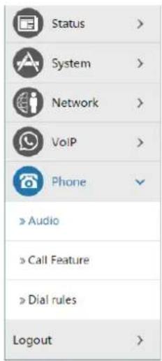
5.4.5 Phone....34
5.4.5.1 Audio....34
5.4.5.2 Call Feature 35
5.4.5.3 Dial rules 37
5.4.5.3.1 Dial Rules 38
5.4.5.3.2 Digital Rule Table....38
5.4.6 Logout....39
6 Trouble Shooting 40
6.1 Reboot Device....40
6.2 Reset Device to Factory Default 40
6.3 Network Packets Capture....40
6.4 Common Problems....41
1 Safety Instruction
Please use the external power supply that is included in the package. Other power supply may cause damage to the device, affect the behavior.
- Before using the external power supply in the package, please check the home power voltage. Inaccurate power voltage may cause fire and damage.
- Please do not damage the power cord. If power cord or plug is impaired, do not use it, it may cause fire or electric shock.
● Do not drop, knock or shake the phone. Rough handling can break internal circuit boards.
- This device is design for indoor use. Do not install the device in places where there is direct sunlight. Also do not put the device on carpets or cushions. It may cause fire or breakdown.
- Avoid exposure the device to high temperature or below 0°C or high humidity.
● Avoid wetting the unit with any liquid.
- Do not attempt to open it. Non-expert handling of the device could damage it. Consult your authorized dealer for help, or else it may cause fire, electric shock and breakdown.
- Do not use harsh chemicals, cleaning solvents, or strong detergents to clean it. Wipe it with a soft cloth that has been slightly dampened in a mild soap and water solution.
- When lightning, do not touch power plug, it may cause an electric shock.
- Do not install this device in an ill-ventilated place. You are in a situation that could cause bodily injury. Before you work on any equipment, be aware of the hazards involved with electrical circuitry and be familiar with standard practices for preventing accidents.
2 About Device
2.1 Product description
G100S is a new VoIP gateway, its core part is a proven solution for VOIP, and so the performance is stable and reliable. Compact appearance, intelligent software and simple interface, making IP gateway no longer limited to enterprise applications, but also for ordinary home users.
2.2 Device Appearance

natural_image
Black rectangular electronic device with control panel and display screen (no visible text or symbols)2.2.1 Interface and Buttons Description
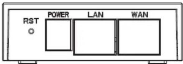
text_image
RST POWER LAN WAN
text_image
2 1| Description Function | |
| RST | Restore Default button. When the device is working properly, if you press this button with a sharp object (such as a pencil) until the CPU fast twinkling (about 5 seconds).Restore function will take effect after you release it. |
| POWER PORT | Connecting to a power source. |
| LAN PORT | Connecting to a computer or a PBX and so on. |
| WAN PORT | Connecting to the network. |
| FXS 1 | Connecting to the analog phone. |
| FXS 2 | N/A |
2.2.2 Indicator Lights Description

flowchart
graph TD
    A["Central Device"] --> B["Analog phone WAN"]
    A --> C["LAN"]
    A --> D["Registered"]
    A --> E["PowerOff"]
After you insert the 12V DC power adapter to this device, power light starts to work, analog phone light comes on, then off! Registered light twinkles for a moment, WAN light and LAN light will be twinkling and then enter standby mode, when you pick up the analog phone, the analog phone light will keep on, when you hang up, the light off!
| Indicator lights | Description Function | |
 | Power Light | off Power is invalid. |
| on Power supply is normal. | ||
 | SIP Registered Light | off SIP is not registered. |
| twinkle SIP registration is failed. | ||
| on SIP registration is successful. | ||
 | LAN Light | off LAN port is not connected. |
| twinkle LAN port is transmitting data. | ||
| on LAN port connection is normal. | ||
 | WAN Light | off WAN port is not connected. |
| Twinkle WAN port is transmitting data. | ||
| on WAN port connection is normal. | ||
 | Analog Phone Light | off |
| on Phone is being off hook. | ||
3 Getting Started
Before you start using the device, please make the following installation:
3.1 Connecting the Power and the Network
3.1.1 Connecting the Network
Before this step, please make sure your environment can satisfy the requirement of broadband network access.
Please connect one end of the network cable to the device's WAN port and the other end connect to your broadband router's LAN port. Now you have completed the network hardware connection. In most of the cases, you need to set your device's network as the DHCP mode. (The default mode of the device is DHCP)

flowchart
graph LR
    A["Internet"] --> B["ADSL / Cable Modem"]
    B --> C["Broadband Router"]
    C --> D["G100S"]
3.1.2 Connecting the Power
Before proceeding with this step, please make sure your power connector and electrical outlet for the agreement, at the same time, the voltage and current are also conform to what the device need.
a) Put the DC port connect to the power port that on the back of the device.
b) Put the AC adapter plug connect to an electrical outlet, the device starts to boot.
c) At this point, all of your indicator lights (except the power light) will twinkle together. After the boot is completed, the indicator lights will be on according to your current configuration. (If your lights is unnormal, we need to further configure your network online mode)
d) If the device has landed on the server, you can start a call right now.
4 Basic Phone Operation
4.1 Call Transfer
a. Blind Transfer:
During a conversation, you press FLASH (Flash) button, enter * and the number you want to transfer, then press [#] key to confirm, you can transfer the current call to the third party. (In order to use the feature, you must enable the gateway Call Waiting function and Call Transfer function)
b. Attended Transfer:
During a conversation, you press FLASH (Flash) button, enter the number you want to transfer ,wait until telephone connected, hang up directly, you can transfer success. (In order to use the feature, you must enable the gateway Call Waiting function and Call Transfer function)
Notes:
- Call Transfer function is implemented under certain condition: there is one way of the two calls is in idle state.
The call between Gateway (transfer side) and phone A is established, then the gateway and the phone C start another call, now you hang up the phone A, the gateway still can initiate a transfer.
Only your network phone traffic service providers support the (RFC3515), can this function work properly
4.2 Call Hold
a. Call Hold and Set Aside
During a conversation, you can press FLASH button, then enter the number to dial and the [#] key to confirm. You can keep your current call and build the third party at the same time. If you press the FLASH (flash) button again, you can switch back. You can only talk with one side while other parties cannot hear your conversation or talk with you. During a conversation, if you press the [*] button, the device will enter the three-party call mode. (To use this feature, you must enable the Call Waiting function of the gateway. To achieve the three-way calling mode, you must enable the Gateway Three Way Call function)
b. Call Hold and Accept Call Waiting
During a normal conversation, if there is third-party dial-in, the handset will be heard beep \~ beep \~ tips, you can use FLASH (flash) button to accept the call waiting. If you press this button
again, you can switch back. You can only talk with one side while other parties cannot hear your conversation or talk with you. (To use this feature, you must enable the Call Waiting function of the gateway)
4.3 Shortcut key
The device can call the corresponding shortcut key through the RJ11 connected analog telephone to realize the related operation.
After the network related operation has been modified, it will need to be restarted before it becomes effective.
-
****: Reboot
-
*100: Switch to static IP mode
-
*101: Switch to DHCP mode
-
*102: Switch to PPPOE mode
-
*103: Switch to bridge mode
-
*104: Off to bridge mode
-
*111: Query IP of WAN port
-
*222: Read phone number
-
*50: Set IP of WAN port
-
*51: Set Gateway of WAN port
-
*52: Set DNS of WAN port
-
*53: Set Subnet Mask of WAN port
-
*90: Cancel the to call transfer
-
*91: Call transfer of busy
-
*92: Call transfer of unconditional
-
*93: Call transfer of no answer
5 Web Configuration
5.1 Ways to Configure
Device offers two different configure ways to different users:
- Use web browser: the computer users who are familiar with the operation of computers. (Recommended use)
- Use the telnet tool: command line users.
5.2 Password Configuration
The setting of the device's browser and command-line can be divided into two login modes: user mode and supervisor mode, under the manager mode, you can view and edit all of the options; while the
When a tip: 'Please enter your password' appeared on the device, you enter different information will into different modes:
- User mode:
◆ Username: admin
◆ Password: admin
- Manager mode:
◆ Username: root
◆ Password: admin
5.3 Browser Configuration
When the device and computer are connected to the network successfully, you enter the device WAN port IP address in the browser (gateway IP address can be get by dialing * 111 #) http://xxx.xxx.xxx.xxx / to see the web management interface login page (as shown below). Enter username and password, click
Username:
Password:


If you have not save your settings, the settings will be restored to the previous state unchanged when you boot phone next time. In order to save your settings, please click the
Note: LAN port IP address (192.168.10.1).
5.4 WEB Pages Function Explanation
5.4.1 Status
5.4.1.1 Overview
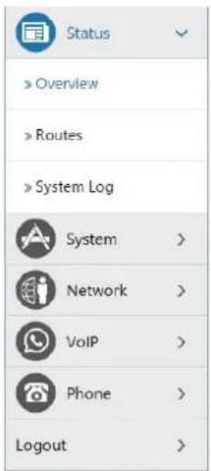
text_image
Status Overview Routes System Log System > Network > VoIP > Phone > Logout >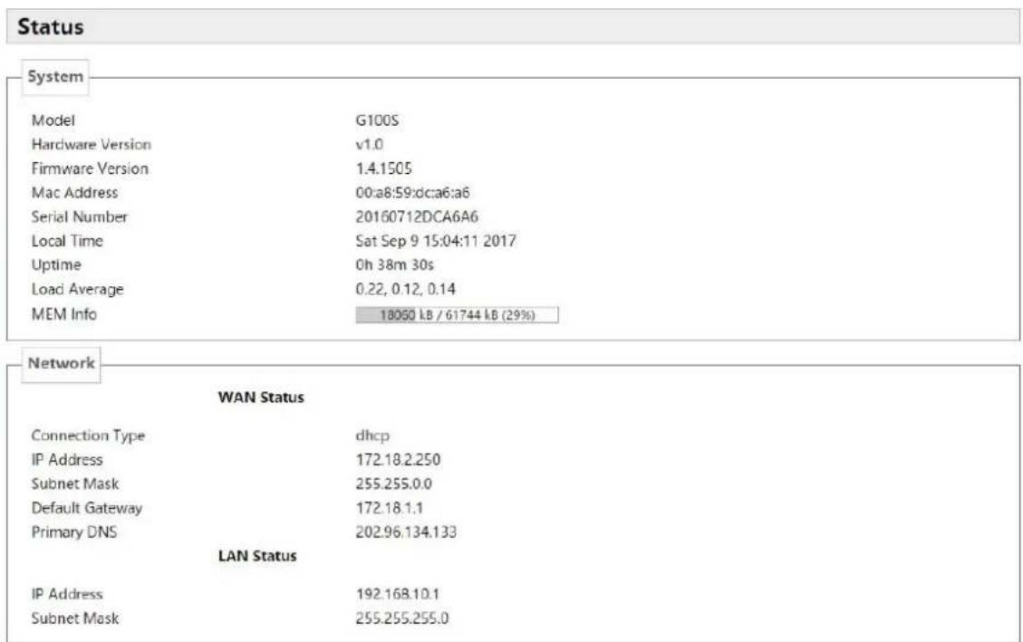
text_image
Status System Model G100S Hardware Version v1.0 Firmware Version 1.4.1505 Mac Address 00:a8:59:dca6:a6 Serial Number 20160712DCA6A6 Local Time Sat Sep 9 15:04:11 2017 Uptime 0h 38m 30s Load Average 0.22, 0.12, 0.14 MEM Info 18050 LB / 61744 LB (29%) Network WAN Status Connection Type dhcp IP Address 172.18.2.250 Subnet Mask 255.255.0.0 Default Gateway 172.18.1.1 Primary DNS 202.96.134.133 LAN Status IP Address 192.168.10.1 Subnet Mask 255.255.255.0Line Status
Line 1
Account
N/A
Server
N/A
Line 2
Account
N/A
Server
N/A
Port 1
OFF
DND
DHCP Leases
Hostname
IPv4-Address
MAC-Address
Leasetime remaining
There are no active leases.
Check-WAN Status
| Name Explanation | |
| System | |
| Model Displays device model. | |
| Hardware Version | Displays device hardware version. |
| Firmware Version | Displays device software firmware version number. |
| MAC Address | Displays the current MAC address. |
| Serial Name | Displays device serial number. |
| Local Time | Displays the current system time |
| Uptime | Displays device runtime |
| Load Average | Displays the current average load value |
| MEM Info | Displays the current memory status |
| Network (WAN Status) | |
| Connection Type | Displays the current networking way. |
| IP Address | Displays the current IP address. |
| Subnet Mask | Displays the current subnet mask. |
| Default Gateway | Displays the default gateway. |
| Primary DNS | Displays the primary DNS. |
| Line status | |
| Displays the current SIP line 1-2 registries number, server and status. | |
| DND | Open this option, any dial-in call will be blocked, the caller will be prompted that the device cannot be used, but you can establish a call with the device. |
| DHCP Leases | Displays host information that has been assigned IP parameters by DHCP |
5.4.1.2 Routes
With this function, you can see the ARP table in the routes. The hosts IP MAC information that had connected with the device recently will be stored in the ARP list.
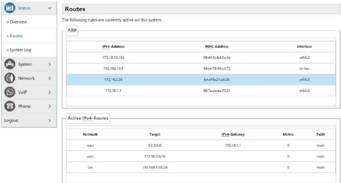
text_image
Status Overview Routes System Log System > Network > VoIP > Phone > Logout > Routes The following rules are currently active on this system. ARP IPv4-Address MAC-Address Interface 172.18.13.102 08.d4.0:c:b8.0:a:6a eth0.2 192.168.10.5 54:ee:75:90:x1:72 bri-lan 172.18.2.26 b4:ef:fa:21:a6:2b eth0.2 172.18.1.1 48.7a:d:e:ea:70:21 eth0.2 Active IPv4-Routes Network也有Target IPv4-Gateway Mctric Table wan 0.0.0.0/0 172.18.1.1 0 main wan 172.18.0.0/16 0 main lan 192.168.10.0/24 0 main5.4.1.3 System Log
It displays activity information of the system.
5.4.2 System
5.4.2.1 System
5.4.2.1.1 General Settings

text_image
System Here you can configure the basic aspects of your device like its hostname or the timezone. System Properties General settings Logging Language Local Time Sat Sep 9 15:07:06 2017 Sync with browser Hostname VoIP Timezone Asia/Shanghai Reset Save & Apply Auto Provision Reboot Auto-Reboot Network >| Name Explanation | |
| General Settings | |
| Local Time Displays the current system time | |
| Hostname | Name of the device, similar to the computer’ name. The default is VoIP, you can modify it by yourself. |
| Timezone Set the time zone of the area where you are. | |
5.4.2.1.2 Logging

text_image
System Here you can configure the basic aspects of your device like its hostname or the timezone. System Properties General settings Logging Language System log buffer size 16 kiB External system log server 0.0.0 External system log server port 514 Log output level Debug Cron Log Level Normal Reboot Reset Save & Apply| Name Explanation | |
| Logging | |
| System log buffer size Set the log buffer size. | |
| External log system server | Set the address of the external log server. |
| External Log server port | Set the port of the external log server. |
| Log output level Set the level of log output. | |
| Cron log level Set the level of Cron log. | |
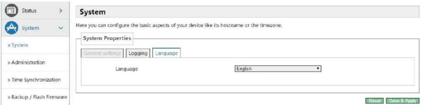
5.4.2.1.3 Language
In this page, you can configure the language that the device currently uses.
text_image
System Here you can configure the basic aspects of your device like its hostname or the timezone. System Properties General settings Logging Language Language English Reset Save & Apply5.4.2.2 Administration
In this page, you can modify the current user's password.
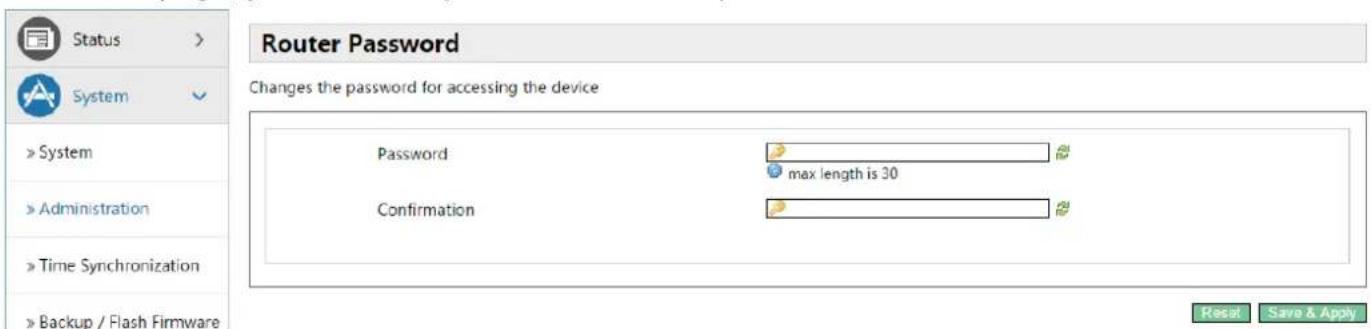
text_image
Router Password Changes the password for accessing the device Password max length is 30 Confirmation Reset Save & Apply5.4.2.3 Time Synchronization
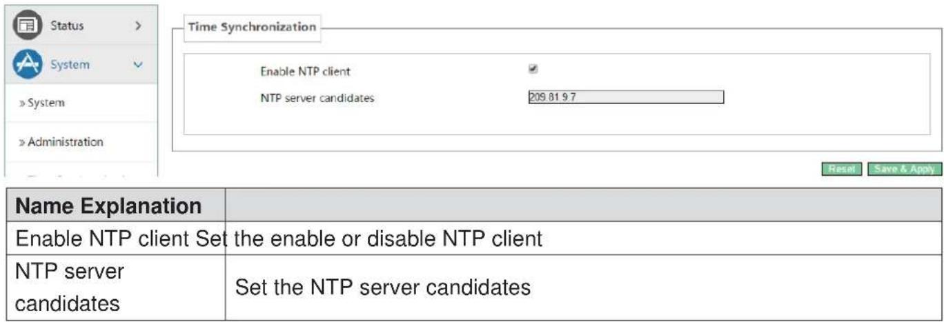
text_image
Status > System » System » Administration Time Synchronization Enable NTP client ✓ NTP server candidates 209.81.9.7 Name Explanation Enable NTP client Set the enable or disable NTP client NTP server candidates Set the NTP server candidates Reset Save & Apply5.4.2.4 Backup/Flash Firmware

text_image
Status System > System > Administration > Time Synchronization > Backup / Flash Firmware > Auto Provision > Reboot > Auto-Reboot Network VoIP Flash operations Actions Configuration Backup / Restore Click "Generate archive" to download a tar archive of the current configuration files. To reset the firmware to its initial state, click "Perform reset" (only possible with squashfs images). Download backup: Generate archive Reset to defaults: Perform reset To restore configuration files, you can upload a previously generated backup archive here. Restore backup: 选择文件 未选择任何文件 Upload archive Flash new firmware image Upload a sysupgrade-compatible image here to replace the running firmware. Check "Keep settings" to retain the current configuration (requires an OpenWrt compatible firmware image). Keep settings: ✓ Image: 选择文件 未选择任何文件 Flash image...| Name Explanation | |
| Backup/Restore | |
| Backup / Restore the current system configuration file or reset PandoraBox. (Squashfs only valid firmware) | |
| Flash new firmware image | |
| Keep settings P | Preserving configuration that currently set. If the option is not selected, thedevice will automatically restore to factory configuration after upgrade. |
| Image | Selects the firmware you need to update, then click<Flash image...>.It is set up. |
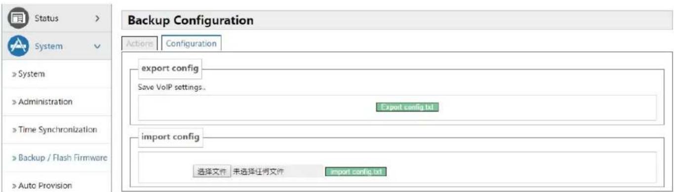
text_image
Status > System > System > Administration > Time Synchronization > Backup / Flash Firmware > Auto Provision Backup Configuration Actions Configuration export config Save VoIP settings.. Export config.txt import config 选择文件 未选择任何文件 import config.txt| Name Explanation |
| Export config |
| Export current device configuration file. |
| Import config |
| Select the profile you need, then clicklt is set up. |
5.4.2.5 Auto Provision

text_image
Common Settings Configuration File Version 2.0002 Server Address 0.0.0.0 Username User Password **** Configuration File Name Encryption Key Protocol Type FTP Update Interval 1 Hour Update Type Disable Check Digest Enable DHCP Option 66 Auto-Reboot System > System > Administration > Time Synchronization > Backup / Flash Firmware > Auto Provision > Reboot > Auto-Reboot| Common Setting | |
| Name Explanation | |
| Configuration File Version | Displays the version number of current system configuration file, if the Terminal founds the CFG configuration file that has downloaded same with configuration file that are running, the device will not run it. Or if the terminal matchesconfiguration file via Digest verification way, as long as the configuration on the server has been modified, or the terminal configure do not match with the configuration on the server, the terminal will to download and update. |
| Server Address | Configures the FTP server address. The server address can be a IP form, such as 192.168.1.1, it may in the form of domain names also, such as ftp.domain.com. And the system also supports server setting subdirectory function, such as the system can configure server address as 192.168.1.1/ftp/Config/form or ftp.domain.com/ftp/config form .It means, the server address to access is 192.168.1.1 or ftp.domain.com, the file storage path is / ftp / Config /. Subdirectory can end without "/". |
| Username | Configures username of FTP server; TFTP protocol need not configuration; if you are using ftp protocol download mode, here is no need to fill, the default is the default user anonymous FTP. |
| Password Configures FTP server user's password. | |
| Configuration File Name | Configures the name of these configuration file need to upgrade; if you use the automatic upgrade feature , this project configuration is empty generally, so our equipment will use its own MAC address as the file name to get the file on the server. |
| Encryption Key | If the configuration file need to update has been encrypted, you need to enter the encryption password in this configuration. |
| Protocol Type Selects the server type. There are three types: FTP, TFTP and HTTP | |
| Update Interval | Configures the interval upgrade time in hours. |
| Update Type | Automatic Update Types:1. Update after rebooting.2. Deactivated.3. Updated regularly.(How often interval updated) |
| Check Digest Configure whether to use Digest mode. | |
| Enable DHCP OPTION 66 | Enable/Disable DHCP option 66 |
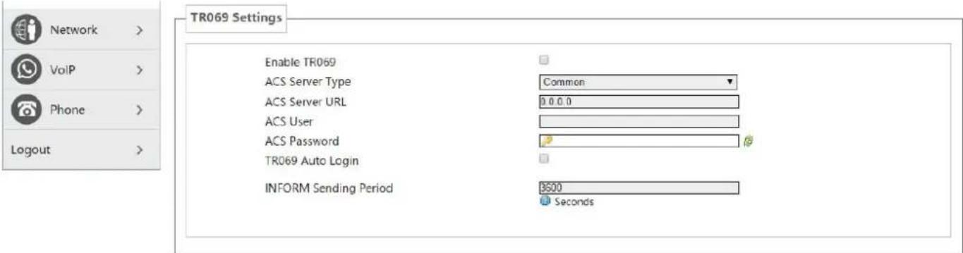
text_image
TR069 Settings Enable TR069 ACS Server Type Common ACS Server URL 0 0 0 0 ACS User ACS Password TR069 Auto Login INFORM Sending Period 3500 SecondsReset Save & Apply
| Name Explanation | |
| Enable TR069 Enable/Disable TR069 | |
| ACS Server type | Used for choosing ACS server type, the terminal supports telecommunications and the general two kinds ACS server currently. |
| ACS Server URL | Enter the ACS server address. |
| ACS User Enter | the ACS server verification username. |
| ACS Password | Enter the ACS server verification user password. |
| TR069 Auto login | If you selected the automatic login, after rebooting the phone, you will not be prompted to enter username and password, but the correct username and password you entered before link to the ACS server. |
| INFORM Sending Period | Check the system every 6 minutes by default. |
5.4.2.6 Reboot
Clicking the
Rebooting will not lost the saved configuration, in the process of rebooting, the network connection will be interrupted temporarily.
Note: During the rebooting, please ensure stable power supply, avoid forced interruption.
5.4.2.7 Auto-Reboot
Config AutoReboot to restart gateway at specific time every day.
5.4.3 Network
5.4.3.1 WAN
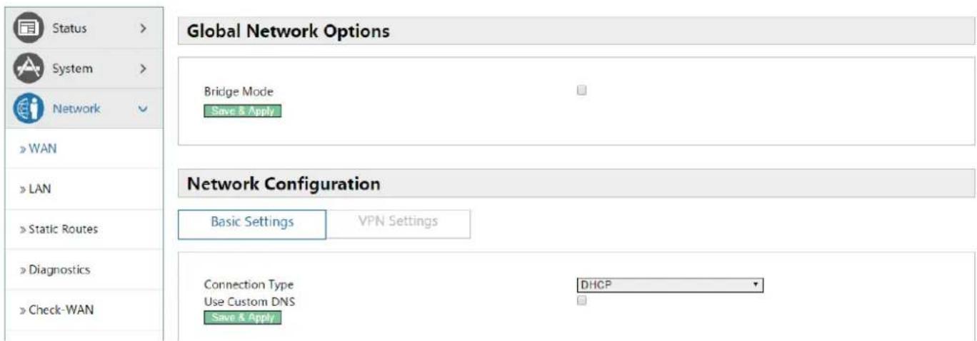
text_image
Global Network Options Bridge Mode Save & Apply Network Configuration Basic Settings VPN Settings Connection Type DHCP Use Custom DNS Save & Apply| Name Explanation | |
| Global Network Configuration | |
| Bridge Mode | Use the bridge mode (transparent mode): Bridge mode will make the device no longer set the IP address for achieving the LAN port, LAN port and WAN port will be connected to the same network. |
| Network Configuration (Basic Settings) | |
| The mode of device connects to the network .According to the network environment, you need to select the appropriate network mode. The device offers three modes: | |
| Static IP | If your ISP server provides a fixed IP address, you can select this mode. After selecting, you must fill in a static table: Static IP address / Subnet Mask / Gateway / DNS and other related information. If you do not know this information, contact your ISP provider or network administrator for assistance. |
| DHCP | When you select this mode, the network-related information will be automatically obtained from the DHCP server, you do not need to manually enter these fields. |
| PPPoE When you select this mode, you must input your ADSL account and password | |
| Use Custom DNS | When you select this mode, you must enter the DNS server address. If you have not, the device will get the DNS server address automatically. |
text_image
Status > System > Network » WAN » LAN » Static Routes » Diagnostics » Check-WAN » QoS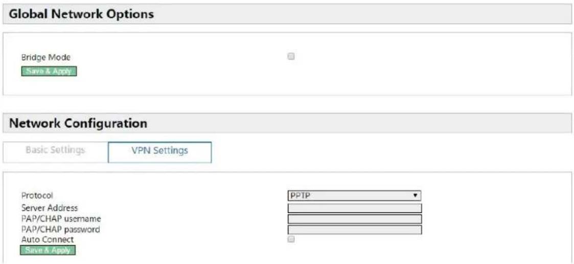
text_image
Global Network Options Bridge Mode Save & Apply Network Configuration Basic Settings VPN Settings Protocol PPTP Server Address PAP/CHAP username PAP/CHAP password Auto Connect Save & Apply| Name Explanation | |
| Network configuration (VPN Settings) | |
| Protocol | Choose the PPTP type, the L2T represents the VPN L2TP, and the PPTP represents VPN PPTP, you must only choose one of them as the current state. |
| Server Address Configures the VPN server address. | |
| PAP/CHAPUsername | Configures the VPN server username. |
| PAP/CHAP Password | Configures the VPN server password. |
| Bring Up on Boot Configures VPN settings auto start after rebooting. | |
5.4.3.2 LAN
| Name Explanation | |
| Common Configuration | |
| IPv4 address Set the IP address to LAN por. Default is 192.168.10.1 | |
| IPv4 netmask Set the netmask to LAN port. Default is 255.255.255.0 | |
| DHCP Server | |
| Ignore interface | Disable DHCP for this interface. |
| Start | Set the IP address Start of DHCP Server. Default is 100 (192.168.10.100). |
| Limit Set the IP address max of DHCP Server. Default is 150 | |
| Leasetime Set the DHCP Leasetime | |
| Static Leases | |
| Static leases are used to assign fixed IP addresses and symbolic hostnames to DHCP clients.They are also required for non-dynamic interface configurations where only hosts with a | |
corresponding lease are served.
5.4.3.3 Static Routes
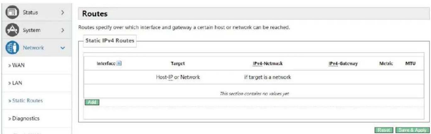
text_image
Routes Routes specify over which interface and gateway a certain host or network can be reached. Static IPv4 Routes Interface Target IPv4-Nctmask IPv4-Gateway Metric MTU Host-IP or Network if target is a network This section contains no values yet Add Reset Save & Apply| Name Explanation | |
| Interface Configures the interfaces sent out by packets. | |
| Target Configures the destination IP address that packets needs to reach | |
| IPv4-Netmask Configures the subnet mask of target IP address | |
| IPv4-Gateway | When you Specify an IP address, the device will next transmit the data packets meet the requirements to this address. |
| Metric The maximum steps number send by packets. | |
| MTU The maximum bytes number send by packets. | |
5.4.3.4 Diagnostics
5.4.3.4.1 Diagnostics
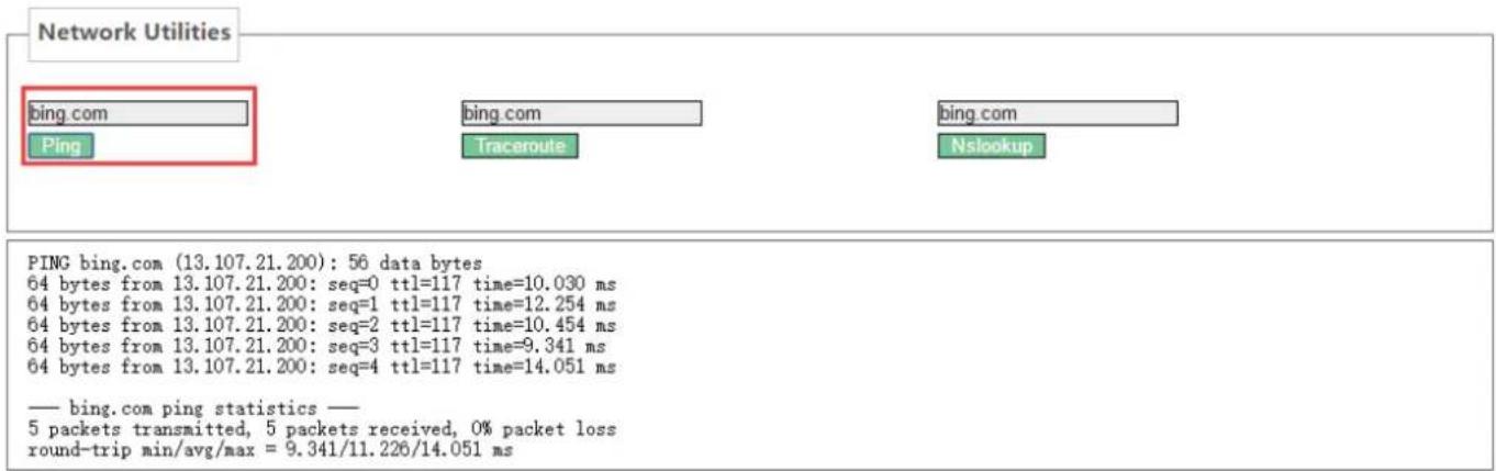
5.4.3.4.1.1 Ping Communication Test
Enter the destination address, which can be a legitimate IP address or a legitimate domain. Click the
text_image
Network Utilities bing.com bing.com bing.com Ping Traceroute Nslookup PING bing.com (13.107.21.200): 56 data bytes 64 bytes from 13.107.21.200: seq=0 ttl=117 time=10.030 ms 64 bytes from 13.107.21.200: seq=1 ttl=117 time=12.254 ms 64 bytes from 13.107.21.200: seq=2 ttl=117 time=10.454 ms 64 bytes from 13.107.21.200: seq=3 ttl=117 time=9.341 ms 64 bytes from 13.107.21.200: seq=4 ttl=117 time=14.051 ms — bing.com ping statistics — 5 packets transmitted, 5 packets received, 0% packet loss round-trip min/avg/max = 9.341/11.226/14.051 msEnter the destination address, which can be a legitimate IP address or a legitimate domain. Click

text_image
Network Utilities bing.com bing com bing com Ping Traceroute Nslookup traceroute to bing.com (204.79.197.200), 30 hops max, 38 byte packets 1 172.18.1.1 1.012 ms 2 113.110.224.1 4.926 ms 3 121.34.244.209 2.223 ms 4 183.56.64.129 2.995 ms 5 183.56.65.10 7.090 ms 6 202.97.35.246 6.800 ms 7 202.97.60.46 11.267 ms 8 202.97.91.86 10.726 ms 9 202.97.121.126 12.051 ms 10 104.44.212.12 10.623 ms 11 * 12 * 13 *Enter the destination address, which can be a legitimate IP address or a legitimate domain. Click
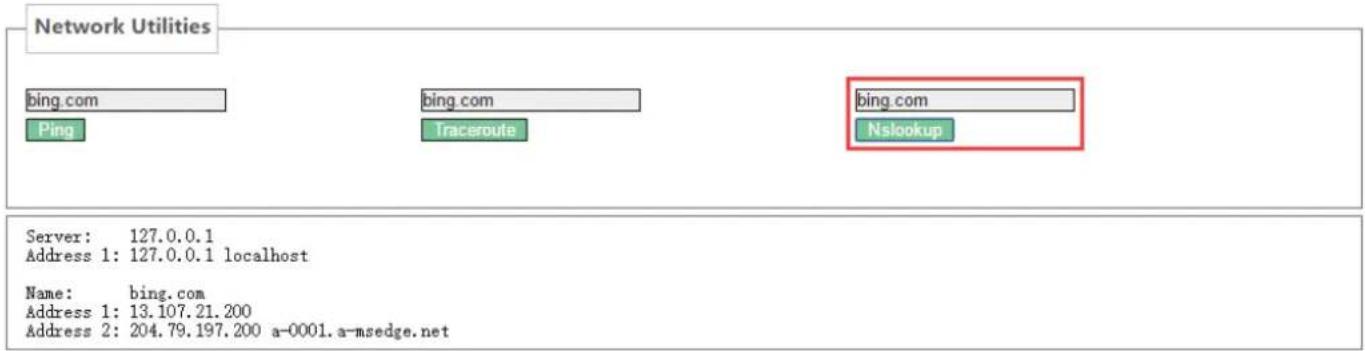
text_image
Network Utilities bing.com ping.com Traceroute bing.com Nslookup Server: 127.0.0.1 Address 1: 127.0.0.1 localhost Name: bing.com Address 1: 13.107.21.200 Address 2: 204.79.197.200 a-0001.a-msedge.net5.4.3.4.2 Network Packets Capture
When you need to catch the packets that through the device wan port, click
| Network Packets Capture |
| start |
5.4.3.5 Check-WAN
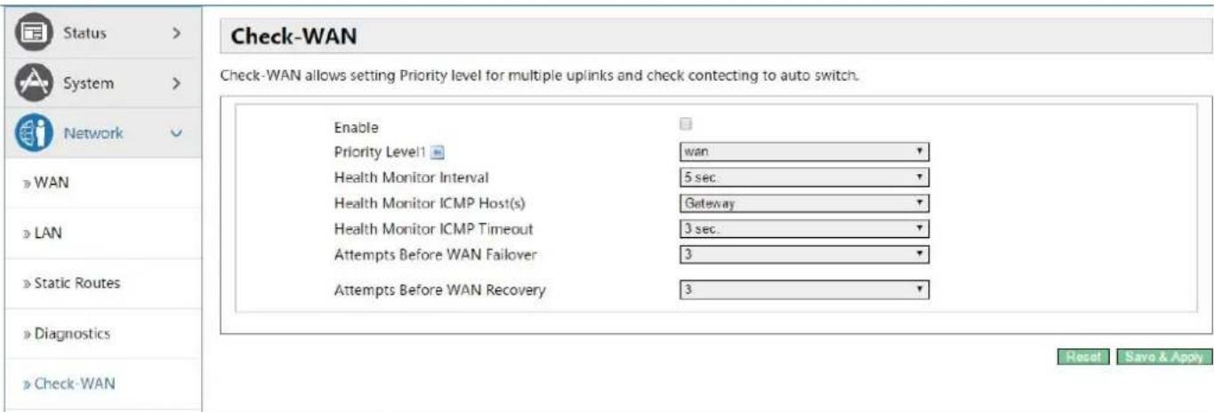
text_image
Check-WAN Check-WAN allows setting Priority level for multiple uplinks and check contacting to auto switch. Enable Priority Level1 ■ wan Health Monitor Interval 5 sec. Health Monitor ICMP Host(s) Gateway Health Monitor ICMP Timeout 3 sec. Attempts Before WAN Failover 3 Attempts Before WAN Recovery 3 Reset Save & Apply| Name Explanation | |
| Enable Select on or off online detection | |
| Priority Level1 Select detection interface | |
| Health Monitor Interval Set the detection interval | |
| Health Monitor ICMP Host(s) Set the ICMP host type (PING detection or DNS detection) | |
| Health Monitor ICMP Timeout Set the ICMP host timeout | |
| Attempts Before WAN Failover Number of attempts before configuring failover | |
Attempts Before WAN Recovery Number of attempts before configuration failure recovery
5.4.3.6 QoS
text_image
Quality of Service With QoS you can prioritize network traffic selected by addresses, ports or services. Interfaces WAN Enable Calculate overhead Half-duplex Download speed (kbit/s) 1024 Upload speed (kbit/s) 128 Add Classification Rules Target Source host Destination host Service Protocol Ports Number of bytes Comment Sort All All All All All 22.53 All All All All TC 20,21,26,8 All All All All all 5190 Add Delete ssh, dns Delete ftp, crntp, htt Delete AOL, iChat DeleteReset Save & Apply
| Name Explanation | |
| Interfaces (WAN) | |
| Enable Set if the current interface to enable QoS service | |
| Classification Group Selects the interface classification group | |
| Calculate Overhead | Set whether to enable the calculation of overhead functions for calculating packets, reduce upload and download rates to avoid link saturation |
| Half-duplex Set whether to enable half duplex mode. | |
| Download Speed Set download speed of the interface, units (kbit / s) | |
| Classification Rules | |
| Target Selects the target priority | |
| Source Host Selects a specific IP as the source host | |
| Destination Host Selects a specific IP as the destination host | |
| Service Selects the application service of what the category groups need . | |
| Protocol The protocol | can be selected as :all optional , TCP, UDP, IGMP, etc. |
| Ports The port number | can be selected as all or a custom specified port. |
| Number of Bytes Fills | the data need to be limited. |
| Comment Fills comment information. | |
| Sort | Set the taxonomic groups sorting , when the targets have same level, the device will prefer to use the preceding rules |
5.4.4 VoIP
5.4.4.1 Line1 & Line2
Here, you can configure the SIP server of SIP 1 and SIP 2.

text_image
Line Settings Status Registered Settings Basic Settings Advanced Settings Server Address 172 18 1 88 Server Port 5060 Authentication User 8207 Authentication Password ****** max length is 60 Phone Number 8207 Display Name 8207 Realm Enable Registration ✓ Status > System > Network > VoIP » Line1 » Line2 » Common » Dial Peer » Debug Phone >| Name Explanation | |
| Status | |
| SIP registration status display: if the registration is successful, it will display ‘Registered’, while not successful will display ‘FAILED’. | |
| Settings(Basic Settings) | |
| Server Address | Configures Your SIP registration server address, supports these address in the form of domain name. |
| Server Port Configures SIP registration server signaling ports. | |
| Authentication User | Configures SIP registration account. |
| Authentication | Configures SIP registration password. |
| Password | |
| Phone Number | Configures the number registered to the SIP server, if it is empty, will not initiate registration. |
| Display Name | Configures the display name, when you make a call, the called party (did not give you a name) can display the configuration parameters that be allowed to input the English alphabet. |
| Realm | Configures SIP local domain name. If the server does not require local domain SIP terminal is the specified domain, local domain can be configured with the address or domain name that same with server. To simplify user input , users can do not enter the domain name, the system will automatically get the server address to fill it as ‘domain realm’. |
| Enable registration | Configures enable/disable registration. |
text_image
Status > System > Network > VoIP » Line1 » Line2 » Common » Dial Peer » Debug Phone > Logout >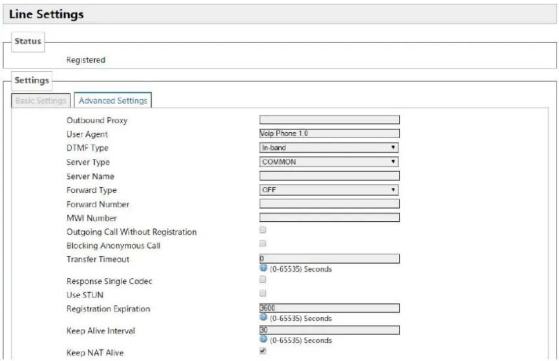
text_image
Line Settings Status Registered Settings Basic Settings Advanced Settings Outbound Proxy User Agent Voip Phone 1.0 DTMF Type In-band Server Type COMMON Server Name Forward Type OFF Forward Number MWI Number Outgoing Call Without Registration Blocking Anonymous Call Transfer Timeout 0 Response Single Codec (0-65535) Seconds Use STUN Registration Expiration 8600 Keep Alive Interval 90 Keep NAT Alive (0-65535) Seconds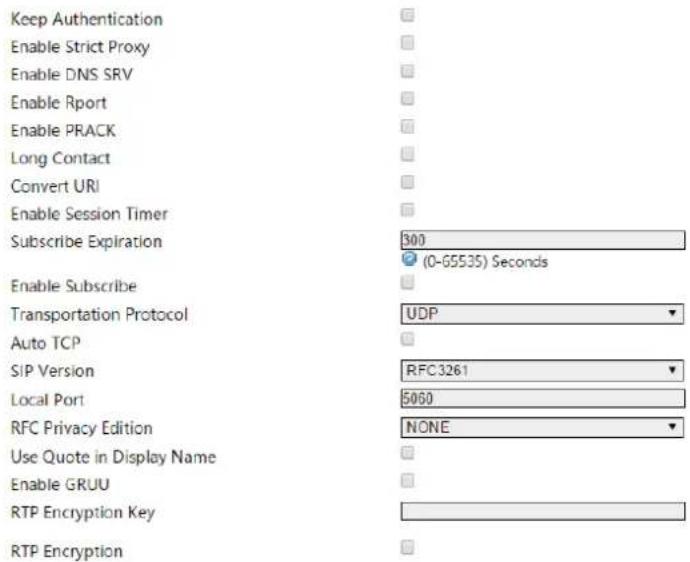
text_image
Keep Authentication Enable Strict Proxy Enable DNS SRV Enable Rport Enable PRACK Long Contact Convert URI Enable Session Timer Subscribe Expiration 300 (0-65535) Seconds Enable Subscribe Transportation Protocol UDP Auto TCP SIP Version RFC3261 Local Port 5060 RFC Privacy Edition NONE Use Quote in Display Name Enable GRUU RTP Encryption Key RTP EncryptionReset Save & Apply
| Name Explanation | |
| Settings (Advanced Settings) | |
| Outbound Proxy | Enter the IP or FQDN address of outbound proxy server provided by the service provider. |
| User Agent User Agent Terminal | |
| DTMF Type | Set DTMF transmit mode, there three types totally : The default is In-bandIn-bandRFC2833SIP_INFODifferent service providers may offer different modes. |
| Server Type Selects | signaling encryption type or special server type |
| Server Name Names | the server. |
| Forward Type | Selects call forward mode. Call Forward (off by default)Off: close call forwardUnconditional: inbound calls will be forwarded to the specified numberBusy: inbound calls will be forwarded to the specified number when the device is buys.No answer: Inbound calls have not been answered after specified time, will be forwarded to the assigned number, during the this proceed, the device will prompt a call. |
| Forward Number Configures the forward number. | |
| MWI Number | Configures the MWI number, achieve Listen to achieve sip voicemail notification and listening . |
| Outgoing Call Without Registration | If you configure this item, you can also call through a proxy server without registration. |
| Blocking Anonymous Call | Configures blocking anonymous call. |
| Transfer Timeout | In order to adapt a platform, when you make the attended transfer and hang up, the session will end after the expire time , the device will send 'bye' initiative; the default is 0 (when you hang up ,the device will send a BYE to end the session immediately ). |
| Response Single Codec | As the called, only in response to the supported Codec. |
| Use STUN Configures enable/disable the SIP STUN. | |
| Registration Expiration | Configures the SIP server registration expiration time, defaults 3600 seconds. If the server requires registration expiration time is more than or less than the device configuration time, the device can be automatically changed as the server recommendation expiration time and re-register. |
| Keep Alive Interval | Configures the server detection time interval, if the gateway opens SIP detection server function, the gateway will detect whether the server responds every configured time. |
| Keep NAT Alive | Configures automatic detection server. Some servers prohibit the registration time is too short, but there have not packet (maintain the device terminal NAT actively) to send, you can open this function and set the interval to send this package is less than NAT duration of time. |
| Keep Authentication | Enable/Disable Keep Authentication System will take the last authentication field which is passed the authentication by server to the request packet. It will decrease the server's repeat authorization work, if it is enable. |
| Enable Strict Proxy | Matches with a special server (when the return message ,the device will use the other party source address ,no longer use the address in via field) |
| Enable DNS SRV | When you open it ,the device will support RFC2782 |
| Enable Rport | Configures if the device support RFC3581,rport mechanism is used in the Intranet, need be supported by SIP server for maintaining the NAT connection of Intranet devices and Extranet devices |
| Enable PRACK | Configures whether let the device support the SIP PRACK function (mostly used for ring tones), we recommend you to use the default configuration |
| Long Contact | Configures Contact field carries more parameters; the item is used with SEM server. |
| Convert URI Convert | # to %23 when URI is sending massage. |
| Enable Session Timer | Configures whether the device support rfc4028 function and refresh the SIP sessions function. |
| Subscribe Expiration | Configures the effective time of subscription |
| Enable Subscribe | After successful registration, subscription information can subscribe to others state or voice mail, etc. |
| Transportation Protocol | Configures the using transport protocol, TCP or UDP, the default is UDP |
| Auto TCP | When the message body exceeds 1300 bytes ,the device will automatically use the TCP transport protocol to guarantee the availability of transport |
| SIP Version | Configures the protocol version. When the device needs to communicate with the gateway like CISCO5300 which uses SIP1.0, you need to configure this item into RFC2543, so it can communicate normally. The default is RFC3261. |
| Local Port Configures | individual port of each line. |
| RFC Privacy Edition | Configures whether you use anonymous security call out, it supports RFC3323 and RFC3325 . |
| Use Quote in Display Name | When the device sending signaling, whether add the quotes before the display name. |
| Enable GRUU Configures | supporting GRUU |
| RTP Encryption Key | Configures voice encryption key |
| RTP Encryption Configures | whether to support voice encryption |
5.4.4.2 Common

text_image
Status > System > Network > VoIP STUN Status False STUN Settings Server Address Server Port 3478 Binding Period 60 Seconds SIP Settings Registration Failure Retry Interval 30 Seconds Sip Invite Restrict ✓ Receive Call Only from UA ✓ Phone > Logout >Reset Save & Apply
| Name Explanation | |
| STUN Status | |
| Displays STUN penetrate judgment, true means STUN is penetrable, false means impenetrable. | |
| STUN Settings | |
| Server Address | Configures SIP STUN Server Address. |
| Server Port Configures | SIP STUN server Port. |
| Binding Period | The interval that STUN detects NAT type ; When NAT finds a connection have no activity over a period of time, it will close the map, so you must send a packet out at intervals to ensure keep alive. |
| SIP Settings | |
| RegistrationFailure RetryInterval | Configures how often the device initiate registration again after registration failure. |
| SIP InviteRestrict | Whether match Invite field strictly. If you selected this item, the SIP message via field that the device received must begin with z9hG4k, or the device will not respond to the SIP message received.NOTE: This configuration will take effect in all SIP accounts. |
| Receive CallOnly from UA | Configures whether match UA strictly. |
5.4.4.3 Dial Peer

text_image
Dial Peer Table Number Destination Port Alias Suffix Deleted Length 5060 no suffix 0 Delete Add Status > System > Network > VoIP » Line1 » Line2 Reset Save & Apply5.4.4.4 Debug

text_image
VoIP Log Set CM Log Level Info SIP Log Level Info Reset Save & Apply| Name Explanation | |
| CM Log Level | Configures the MGR Log Level. |
| SIP Log Level | Configures the SIP Log Level. |
5.4.5 Phone
5.4.5.1 Audio
text_image
Status > System > Network > VoIP > Phone Audio Call Feature Dial rules Logout >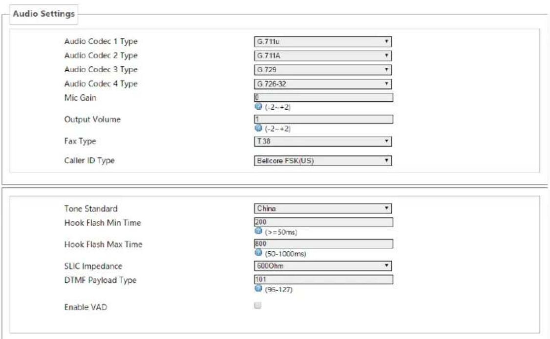
text_image
Audio Settings Audio Codec 1 Type G 711u Audio Codec 2 Type G 711A Audio Codec 3 Type G 729 Audio Codec 4 Type G 726-32 Mic Gain 0 (-2~+2) Output Volume 1 (-2~+2) Fax Type T 38 Caller ID Type Bellcore FSK(US) Tone Standard China Hook Flash Min Time 200 (>=50ms) Hook Flash Max Time 800 (50-1000ms) SLIC Impedance 600Ohm DTMF Payload Type 101 (96-127) Enable VAD| Name Explanation | |
| Audio Settings | |
| Audio Codec 1 Type | Selects DSP the first priority speech coding algorithm: G.711A/u,G.726-32, G.729 |
| Audio Codec 2 Type | Selects DSP the second priority speech coding algorithm: G.711A/u,G.726-32, G.729 |
| Audio Codec 3 Type | Selects DSP the third priority speech coding algorithm: G.711A/u,G.726-32, G.729 |
| Audio Codec 4 Type | Selects DSP the fourth priority speech coding algorithm: G.711A/u,G.726-32, G.729 |
| MIC Gain Set the microphone volume level. | |
| Handset volume Set the handset volume level. | |
| Fax Type Set the fax type. | |
| Caller ID Type | Set the PSTN phones that only support transferring Caller ID under DTMF mode. |
| Tone Standard Selects tone standard. | |
| Hook Flash Min Time | Set the minimum time of inserted spring detection. |
| Hook Flash Max Time | Set the maximum time of inserted spring detection. |
| SLIC Impedance Set | subscriber line interface circuit impedance, the default is 600 ohms. |
| DTMF Payload Type | Effective load of dual-tone multifrequency. |
| Enable VND | Silence detection; if it is enabled VAD, G.729 payload length cannot be set higher than 20ms |
5.4.5.2 Call Feature
On this page, you can set the hotline, call transfer, call waiting, three way call, black list, Blocking list and so on.
text_image
Status > System > Network > VoIP > Phone »Audio »Call Feature »Dial rules Logout >
text_image
Call Feature Hotline number Warm Line Timeout No Answer Time Do Not Disturb(DND) Blocking Outgoing Call Enable Three Way Call Enable Call Waiting Enable Call Transfer P2P IP Prefix Accept Any Call
text_image
Black List This section contains no values yet Add Blocking List This section contains no values yet AddReset Save & Apply
| Name Explanation | |
| Call Feature | |
| Hotline Number | Set the Hotline Number. If you set this number, as long as you goes off-hook, the device will automatically dial the hotline number and you cannot dial any other number. |
| Warm Line Timeout | Set automatically dial the hotline number time after off-hook .If you set this item as 0, device will call the hotline number immediately after you off-hook. |
| No Answer Time | Set the no answer time. |
| Do Not Disturb | If you selected this item, the device will reject any incoming calls, the caller will be prompted that the other side gateway is unavailable; your device can dial out without any effect. |
| Blocking Outgoing Call | When it is enable, the device will send buys tone and prompt you to hang up when you off-hook and then dial. |
| Enable Three Way Call | Enable three way call. |
| Enable Call Waiting | Enable call waiting |
| P2P IP Prefix | Set point-to-point IP call prefix, such as the other side IP is 192.168.1.119, then you defined here as 192.168.1., just dial # 119, can make a point-to-point IP call. |
| Accept Any Call | When you selected this option, as long as the other side call you, the device will allow to make a conversation regardless of the number correctness. |
| Enable Call Set | whether to enable call Transfer. |
| Transfer | |
| Black List | |
| Add / Delete blacklist. If you do not want to answer a certain number ,can add the number to this list, when the number in black list call your device, the device will reject it;It supports x format, that is, match to any one digit, such as 4xx represents these three digits number begin with 4 will be forbidden dial in;Supported .formats, that is match to any length, including the null; Such as 6. represents the number more one digit and begin with 6 will be forbidden dial in; | |
| Blocking List | |
| Call limit, set the number prefix form : if 010 as configured number prefix, you will hear busy tone and be prompted to hang up when you dial 010,so you cannot continue dial: if 0 as configured number prefix, you will cannot dial all numbers begin with 0;It supports x form, that is, match any one digit, such as 4xx represents all three digit number begin with 4 will be forbidden to dial out;It supports . form ,that is match to any length, including the null; such as 6. Represents all number begin with 6 will be forbidden to dial out . | |
| Note: Black List and Blocking List can match 10 records maximumly. If more than 10, it will prompt the list is full. | |
5.4.5.3 Dial rules

text_image
Status > System > Network > VoIP > Phone » Audio » Call Feature » Dial rules Logout > Dial rules Press # to invoke dialing Use Fixed Length Fixed Length 11 1-30 Invoke Calling after Timeout Timeout 5 (3-30)Seconds Digital Rule table Rules This section contains no values yet AddReset Save & Apply
5.4.5.3.1 Dial Rules
| Name Explanation | |
| Press # to invoke dialing | Set the gateway to press the # key to finish receiving number. |
| Use Fixed Length | Set enable\disable use fixed length to dial. |
| Fixed Length | Set the gateway to receive a fixed length number; for example, if you set it as 11, when you finished dialing 11 digits number, the gateway automatically dial the 11 digits number. |
| Invoke Calling After Timeout | Enable/disable calling after timeout. |
| Timeout | Set the timeout calling length in seconds. Gateway default is 5 seconds, that is , when the gateway received a number, it will deem that you have finished dialing the number after you have not continue dialing a number in 5 seconds ,and it will dial the received number. |
5.4.5.3.2 Digital Rule Table
The following is user-defined number-receiving rule table:
- [] is defining the number range. It can be a range, can be separated by a comma, it can also be a digit of list;
- x means can math to any one digit;
● . means can match to any length, including the null; - Tn means the device will stop receiving number after n seconds. n is mandatory, the range is 0-9 seconds. Tn must be the last two digits setting. If Tn is not specified, it will be assumed as T0, the receiving number will end immediately.
As shown below:
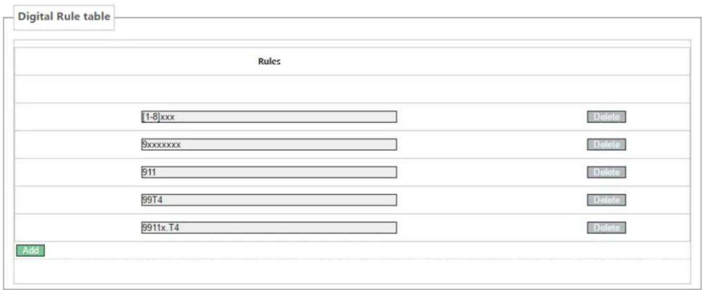
text_image
Digital Rule table Rules [1-8]xxx 9xxxxxxx 911 99T4 9911x.T4 Delete Delete Delete Delete Delete Add- [1-8]xxx, means all the four digits number(1000-8999) will be sent out immediately after receiving four digits number.
- 9xxxxxxx, means all number begin with 9 will be send out immediately after receiving eight digits number.
● 911, means the 911 number will be sent immediately after dialing.
● 99T4, means when you finish dialing 99, the number will be send out after 4 seconds. - 9911x.T4, means when you finish dialing a number begin with 9911, 5 digits at least, it will be sent out after 4 seconds.
● Other ways is unchanged.
Note: Press # to invoke dialing, Use fixed length, Invoke Calling after Timeout, Digital Rules table can be used simultaneously, as long as when you finish dialing a number, the number satisfies any of these judgments, the device will end receiving number and send the number out.
5.4.6 Logout
Click
6 Trouble Shooting
When the device does not work properly, users may try the following methods to recover the device or gather relative information and send an issue report to support.
6.1 Reboot Device
Users may reboot the device from power switch. Or, simply remove the power supply and restore it again.
6.2 Reset Device to Factory Default
Reset Device to Factory Default will erase all user's configuration, preference, database and profiles on the device and restore the device back to the state as factory default.
To perform a factory default reset, Press the RST button for 3\~5 seconds and then release. The device will be rebooted into a clean factory default state.
6.3 Network Packets Capture
Sometimes it is helpful to dump the network packets of the device for issue identification. To get the packets dump of the device, user needs to log in the device web portal, open page [Network] -> [Diagnostics] and click [Start] in “Network Packets Capture” section. A pop-up message will be prompt to ask user to save the capture file. User then should perform relevant operations such as activate/deactivate line or making phone calls and click [Stop] button in the web page when operation finished. The network packets of the device during the period have been dumped to the saved file. User may examine the packets with a packet analyzer or send it to support.
6.4 Common Problems
| Symptom Solution | |
| POWER light is not on | 1. Check if the power switch is open.2. Check if the power connection is correct.3. Check if the power adapter is suited. |
| WAN/LAN link light is not on | 1. Check if the cable connection is valid, check if the PC network card indicator light is on.2. Check if the network card is working properly, the specific approach is to see if there is the device with "?" Or "!" under the Network Adapter" of the PC. If so, please delete the device and reinstall. Otherwise, put the network card in another slot, if not yet, change the network card. |
| Can not access the network | Such as the common access modes(your PC have already installed dial-up software):1. Make sure the front problem does not exist.2. Make sure the dial-up software is properly installed and set.3. Make sure you entered correct username and password .4. If you call successfully dial, but cannot access the network, please make sure if the IE browser's proxy server is set correctly.5. Please try to log more websites to confirm if it is because of a Web server failure. |
| Device could not register to a service provider | 1. Please check if device is well connected to the network. The network Ethernet cable should be connected to the [Network] port NOT the [PC] port.2. Please check if the device has an IP address. If the device does not have an IP address. Please check if the network configurations is correct.3. If network connection is fine, please check again your line configurations. If all configurations are correct, please kindly contact your service provider to get support, or follow the instructions in “6.3 Network Packet Capture” to get the network packet capture of registration process and send it to support to analyze the issue. |