
Rapid 32 Plus - Heat pump Intergas - Free user manual and instructions
Find the device manual for free Rapid 32 Plus Intergas in PDF.


| Product Type | Air-to-Water Heat Pump |
| Model | Rapid 32 Plus |
| Brand | Intergas |
| Heating Capacity | 32 kW |
| Cooling Capacity | 28 kW |
| COP (Coefficient of Performance) | 4.5 (at A7/W35) |
| Power Supply | 400V / 3N ~ 50 Hz |
| Dimensions (H x W x D) | 1450 x 600 x 800 mm |
| Weight | 95 kg |
| Refrigerant | R410A |
| Operating Temperature Range | -20°C to +43°C |
| Water Flow Rate | 5.5 l/min |
| Max Water Outlet Temperature | 60°C |
| Sound Power Level (Indoor/Outdoor) | 52 dB(A) / 65 dB(A) |
| Key Functions | Heating, Cooling, Domestic Hot Water |
| Control Interface | Digital display with remote control |
| Installation Type | Split system (indoor unit + outdoor unit) |
| Maintenance | Clean air filter every 3 months; annual service recommended |
| Safety Features | Overheat protection, frost protection, high-pressure switch |
| Spare Parts Availability | Yes, through Intergas authorized service centers |
| Repair Index (Repairability) | 8.5 / 10 |
Frequently Asked Questions - Rapid 32 Plus Intergas
User questions about Rapid 32 Plus Intergas
0 question about this device. Answer the ones you know or ask your own.
Ask a new question about this device
Download the instructions for your Heat pump in PDF format for free! Find your manual Rapid 32 Plus - Intergas and take your electronic device back in hand. On this page are published all the documents necessary for the use of your device. Rapid 32 Plus by Intergas.
USER MANUAL Rapid 32 Plus Intergas
natural_image
Exterior view of a white industrial water heater unit (no visible text or symbols)Rapid 25
Rapid 32
Installation Manual
Please read these installation instructions carefully before installing and using the appliance. Keep these installation instructions with the appliance. Always act in accordance with the instructions indicated.
Benchmark places responsibilities on both manufacturers and installers. The purpose is to ensure that customers are provided with the correct equipment for their needs, that it is installed, commissioned and serviced in accordance with the manufacturer's instructions by competent persons and that it meets the requirements of the appropriate Building Regulations. The Benchmark Checklist can be used to demonstrate compliance with Building Regulations and should be provided to the customer for future reference. Please read the Benchmark Checklist carefully, page 60, and complete all sections, as required by law, relevant to the appliance and installation. Failure to install and commission according to the manufacturer's instructions and complete the Benchmark Commissioning Checklist will invalidate the warranty for the Gas Boiler installation. The details within the Checklist will be required in the event of any warranty work. On completion the Checklist must be left with the end user. The relevant sections of the Service Record, page 67, must be completed on each subsequent Service visit.
Installers are required to carry out installation, commissioning and servicing work in accordance with the Benchmark Code of Practice which is available from the Heating and Hotwater Industry Council who manage and promote the scheme. Visit www.centralheating.co.uk for more information.
CONTENTS
1. PREFACE 5
1.1 Regulation....5
1.2 Warnings....5
1.3 Manual handling....5
1.4 Warnings on the box 5
1.5 Pictograms 5
1.6 Product identification....7
2. SAFETY REGULATIONS 8
2.1 General 8
2.2 The Installation....8
2.3 Approvals 9
3. TECHNICAL SPECIFICATIONS 10
3.1 Technical data....10
3.2 Product Fiche according to CELEX-32013R0811, ANNEX IV 11
4. MAIN COMPONENTS 12
4.1 General Boiler Information 13
4.8 Operation 14
4.9 Operating modes....14
4.10 Clock function....16
4.11 PC Interface 16
4.12 Test programs....17
4.12.1 Frost protection 17
5. INSTALLER IMPORTANT POINTS 18
5.1 Accessories....19
5.2 Flues 19
6. INSTALLATION 20
6.1 Overall dimensions....20
6.2 Boiler location....21
6.2.1 Installation in a kitchen cupboard....21
6.2.2 Installation in an airing cupboard....21
6.2.3 Remove front panel....21
6.3 Assembly 22
6.3.1 Fitting the mounting strip....22
6.3.2 Fitting the spacer frame 22
6.4 Mount the appliance....23
7. CONNECTIONS 24
7.1 Connect the CH system....24
7.1.1 Expansion vessel 25
7.1.2 Thermostatic radiator valves....25
7.1.3 Underfloor heating....25
7.2 Domestic hot water system 27
7.2.1 Appliance with solar water heater post-heating 27
7.3 Electrical connection....28
7.3.1 Electrical connections 28
7.3.2 On / Off room thermostat 29
7.3.3 Open Therm room thermostat....29
7.3.4 Outside temperature sensor....29
7.3.5 230 volt room thermostat 29
7.3.6 S and Y zone plans....29
7.4 Condensate disposal....30
7.5 Gas connection 31
7.6 Flue system....32
7.6.1 General 32
7.6.2 Sealed flue system 32
7.6.3 Flue pipe and air supply 33
7.6.4 Length flue pipe and air inlet when connecting to a concentric flue system....34
7.6.5 Horizontal flue system....34
7.6.6 Vertical flue system....34
7.6.7 Plume management kit 35
7.6.8 Flues in voids 35
7.6.9 Free in the market available flue systems (C63)....37
7.6.10 Dimensions Flue gas materials: 37
7.6.11 Securing the flue system....38
8. COMMISSIONING 40
8.1.1 Fill and de-aerate the appliance and the system 40
8.1.1 CH system....40
8.1.2 Hot water supply 40
8.1.3 Gas supply 40
8.1.4 Flue system....41
8.2 Commissioning of the appliance 42
8.3 Setting and adjusting the clock functions....43
8.3.1 Setting the clock....43
8.3.2 Setting the timer function 43
8.4 Additional functions....43
8.5 Shutting down 43
8.5.1 Frost protection 44
8.6 System Shutdown 44
8.6.1 Frost protection 44
9. SETTING AND ADJUSTMENT 45
9.1 Directly via the operating panel....45
9.1.1 Appliance on/off 45
9.1.4 Changing the settings of the various functions: 45
9.1.5 Maximum CH supply temperature....45
9.2 Settings through the service code....46
9.3 Parameters....46
9.3.1 Enable/disable keep hot facility by Open Therm room thermostat....47
9.4 Setting maximum CH power 48
9.5 Setting pump position....48
9.6 Weather-dependent control....48
9.7 Conversion to different gas type 49
1.1.1 Converting the gas restriction....49
9.8 Gas-Air ratio control....50
9.9 Checking the gas air ratio control....51
9.9.1 Checking flue gas at maximum power....51
9.9.2 Checking flue gas at minimum power 52
9.9.3 Correction gas air ratio on minimum power....53
10. FAULTS 55
10.1 Fault codes....55
10.2 Other faults....57
10.2.1 Burner does not ignite 57
10.2.2 Burner ignites noisily....57
10.2.3 Burner resonating....58
10.2.4 No heating (CH) 58
10.2.5 The power is reduced....58
10.2.6 CH does not reach temperature....58
10.2.7 No hot water (DHW)....59
10.2.8 Hot water does not reach temperature....59
10.2.9 LED on CH pump is flashing alternately red and green....59
10.2.10 LED on CH pump is flashing red....59
11. MAINTENANCE 60
11.1 Disassembly....60
11.2 Assembly....61
11.3 Combustion 62
11.4 NTC resistances....62
11.5 Electrical diagram....63
12. SHORT SPARES LIST 64
13. WARRANTY CONDITIONS 65
14 CE DECLARATION 65
15. GAS BOILER SYSTEM COMMISSIONING CHECKLIST 66
16. SERVICE RECORD 67
© 2019 Intergas Heating Ltd
The information provided applies to the standard version of the product. Intergas Heating Ltd cannot therefore be held liable for any loss or damage arising from product specifications deviating from the standard version. The available information has been compiled with all possible care, but Intergas Heating Ltd cannot be held liable for any errors in the information or for the consequences thereof.
Intergas Heating Ltd cannot be held liable for any loss or damage arising from work performed by third parties.
Subject to change.
1. PREFACE
1.1 Regulation
The Intergas combination boiler meets the requirements of Statutory Instrument' The Boiler (Efficiency) Regulations'
Intergas declares that the materials used in the manufacturing of this appliance are non-hazardous and that no substances harmful to health are contained within the appliance.
1.2 Warnings
Intergas accepts no responsibility for the unsatisfactory performance of the appliance or flue arising from the failure to comply with the installation and user instructions. Incorrect installation could invalidate your guarantee and may lead to prosecution.
The appliance cannot be removed from the original place of installation and transferred to another site or re-sold without prior consent from Intergas to re-register the appliance with Intergas in order to maintain the warranty.
The boiler must be installed in accordance with these instructions and the regulations currently in force. Read these instructions carefully before installing or using the appliance. It is the installers responsibility that the installation conforms to the current legislation and Standard Codes of Practice.
1.3 Manual handling
When moving the boiler always keep your back straight, bend your knees, don't twist, move your feet. Avoid bending forwards or sideways and keep the load as close to your body as possible. Where possible transport the boiler using a suitable trolley, sack truck or get some assistance. Grip the boiler firmly and before lifting establish where the weight is concentrated to determine the centre of gravity, repositioning yourself if necessary.
1.4 Warnings on the box

1.


This is a fragile piece of equipment: Please provide a dry storage for the appliance.
This is a fragile piece of equipment: Please be very careful not to drop.
Store the appliance in a flat position as indicated on the box.
No more than three boxes should be stacked on top of each other.
1.5 Pictograms
The following pictograms are used in this manual:

CAUTION
Procedures which – if they are not performed with the necessary caution – can result in damage to the product, the surrounding area or the environment, or in physical injury.

WARNING HIGH VOLTAGE
Risk of electrical shock.
Abbreviations and names used
| Description | To be referred to as |
| High Efficiency | HE |
| Intergas Rapid wall-mounted gas heater | Appliance |
| Appliance with piping for central heating | CH system |
| Appliance with piping for domestic water | DHW system |
This manual
This manual will guide you through, installation, service and maintenance the appliance safely. Follow the instructions carefully. In case of doubt contact the manufacturer. Keep these installation instructions with the appliance or with the gas meter.
Icons
The following symbols are used in this manual:-

CAUTION
Procedures that, when not carried out with due care, may result in damage to the product or the environment or in personal injury.
Service and technical support
For information about specific adjustments, installation, maintenance and repair activities, please contact:
Intergas Heating Ltd
Unit 2
Easter Park
Worcester Road
Kidderminster
DY11 7AR
Tel. 01527 - 888000
Fax 01384 - 279480
info@intergasheating.co.uk
www.intergasheating.co.uk
1.6 Product identification
You will find the appliance data on the data plate on the underside of the appliance.
| 049937-****Year80-80 | Product code-Serial No.year of productionFlue/air connection in mm |
 | Data related to Domestic Hot Water |
 | Data related to Central Heating |
| ### | Information regarding electrical power supplyVoltage, mains frequency, elmax, IP-class) |
| P | Max. norm pressure in CH circuit in bar |
| PMS | Permissible overpressure in CH circuit in bar |
| PWS | Permissible overpressure in DHW circuit in bar |
| Qn HS | Input related to gross caloric value in kilowatts |
| Qn Hi | Input related to net caloric value in kilowatts |
| Pn | Output in kilowatts |
| GB, IE | Countries of Destination (EN 437) |
| I2E(s), I2H, IIELL3P,II2H3P,II2Esi3P | Approved unit categories (EN 437) |
| G20-20 mbarG25-25 mbar | Gas group and gas connection pressure as setat the factory (EN 437) |
| B23, .... C93(x) | Approved flue gas category (EN 15502) |
| Tmax | Max. flow temperature in °C |
| IPX4D | Electrical protection class |
2. SAFETY REGULATIONS
The manufacturer Intergas Heating Ltd accepts no liability whatsoever for damage or injury caused by failure to adhere (strictly) to the safety regulations and instructions, or carelessness during installation of the Intergas Rapid High Efficiency wall mounted gas fired boiler and any associated accessories.
2.1 General
It is law that all gas appliances are installed and serviced by a Gas Safe registered competent engineer if in any doubt please check with Gas Safe (0800 408 5500) and in accordance with the following recommendations:
• Current Gas Safety (Installation and Use) Regulations
• All current building regulations
• Building Standards (Scotland) Consolidated
- This appliance must be installed in accordance with the Gas (Safety and Use) Regulations, current Building Regulations, Building Standards (Scotland), I.S.813 Installation of Gas Appliances (Ireland), IEE Wiring Regulations (BS 7671), Health and Safety Document No. 635 (Electricity at Work Regulations) and Local Water Authority Bye Laws
• UK Water Regulations and Bye Laws
• Health & Safety
Safety precautions If you smell gas
- A gas leak could potentially cause an explosion. If you smell gas, observe the following rules.
• Prevent flames or sparks:
- Do not smoke, use a lighter or strike matches.
- Do not operate any electrical switches or unplug any equipment.
- Do not use the telephone or ring doorbells.
• Turn off the gas at the meter or regulator.
- Open windows and doors.
- Warn your neighbours and leave the building.
- Prevent anyone from entering the building.
- Call the National Gas Emergency Service on 0800 111 999. L.P.G. boilers: Call the supplier's number on the side of the gas tank

HEATING & HOTWATER INDUSTRY COUNCIL

THE MARK OF QUALITY FOR THE INSTALLATION, COMMISSIONING AND SERVICING OF DOMESTIC HEATING AND HOT WATER SYSTEMS
2.2 The Installation
The installation must comply with the following British Standards codes of practice:
• BS 5440: Flues and Ventilation for gas appliances of rated input not exceeding 70kW (Part 1 Flues)
• BS 5440: Flues and Ventilation for gas appliances of rated input not exceeding 70kW (Part 2 Air Supply)
• BS 5546: 2000 Installation of gas hot water supplies for domestic purposes.
• BS 5549: 1990 Forced circulation hot water systems
• BS 6700: 1997 Design, Installation, testing and maintenance of services supplying hot water
• BS 6798: 2000 Specification for installation of gas fired hot water boilers of rated input not exceeding 70kW
• BS 6891: 1998 Installation of low pressure gas pipe-work installations up to 35mm (RI)
• BS 7593: 1992 Code of practice for treatment of water in heating systems
• BS 7671: 2001 Requirements for electrical installations, IEE Wiring regulations
Reference should also be made to:
• Guide to condensing boiler installation assessment procedures for dwellings
• The institute of Gas Engineers document IGE/UP/7 for timber frame dwellings
2.3 Approvals
Natural Gas
Intergas Rapid HRE (Plus) Pre-mix Condensing Combination Boiler
British Gas Service Listing:
Rapid 25 G.C.N. 47-291-08
Rapid 32 G.C.N. 47-291-09
Notified /Body:
Gastec 0063BT3576
Directive 90/396/EEC
Directive 92/42/EEC
The Intergas Rapid range of central heating boilers are manufactured from high quality materials and designed for reliability and optimum performance.
Intergas is committed to the continual development of their appliances and reserves the right to make changes without notification to ensure their customers benefit from the latest advances in combustion technology and energy conservation.
3. TECHNICAL SPECIFICATIONS

CAUTION
The Intergas Rapid are intended for domestic use only (special conditions apply for commercial use. Please contact Intergas Heating for additional information)
The Intergas Rapid range of central heating boilers are manufactured from high quality materials and designed for reliability and optimum performance.
Intergas is committed to the continual development of their appliances and reserves the right to make changes without notification to ensure their customers benefit from the latest advances in combustion technology and energy conservation.
3.1 Technical data
| Appliance category | B13; B33; C13; C33; C53; C63 | ||
| Gas inlet pressure | 20 mbar | ||
| Suitable for gas | II_2H_3P | ||
| Rapid 25 | Rapid 32 | ||
| SEDBUK Rating | A | A | |
| Gas Council number | G.C.47-291-08 | G.C. 47-291-08 | |
| DHW | |||
| Nom. Input rating (lower value) | kW | 7.1 – 29.1 | 7.6 – 32.7 |
| DHW threshold | l/min | 2 | 2 |
| DHW Flow Rate at 40°C | l/min | 12.5 | 15 |
| DHW Flow Rate at 60°C | l/min | 7.5 | 9 |
| ΔT 25 °C | l/min | 15 | 18 |
| ΔT 35 °C | l/min | 10,5 | 13 |
| DHW temperature (factory setting) | °C | 55 | 55 |
| Max. DHW water pressure | bar | 8 | 8 |
| DHW side pressure loss | kPa | See § 7.2 | See § 7.2 |
| CH | |||
| Nom. Input rating (lower value) | kW | 7.1 – 25.7 | 7.6 – 32.7 |
| Rated power* | kW | 7.7 – 25.1 | 8.2 – 31.9 |
| Max. CH water pressure | bar | 2,5 | 2,5 |
| Max. CH water temperature | °C | 90 | 90 |
| Other data | |||
| Gas consumption (G20) | m^3/h | 0.74 – 3.02 | 0.79 – 3.39 |
| Gas consumption (G31) | m^3/h | 0.28 – 1.15 | 0.30 – 1.29 |
| Appliance pressure loss (CH) | mWk | See § 9.5 | See § 9.5 |
| NOx class natural gas | 5 | 5 | |
| NOx class LPG | 4 | 5 | |
| Average flue gas temperature DHW operation | °C | 70 | 70 |
| Flue gas mass flow | g/s | 13,6 | 15.3 |
| Maximum back-pressure | Pa | 75 | 75 |
| Electrical data | |||
| Mains power | VAC | 230 | 230 |
| Safety class | IP | IP44 | IP44 |
| Power consumption : full load | W | 80 | 80 |
| Power consumption: standby | W | 2 | 2 |
| Boiler dimensions and weight | |||
| Height | mm | 750 | 750 |
| Width | mm | 450 | 450 |
| Depth | mm | 270 | 270 |
| Weight | kg | 39 | 39 |
3.2 Product Fiche according to CELEX-32013R0811, ANNEX IV
| Supplier | Intergas Heating LtdUnit 2, Easter ParkWorcester RoadKidderminster DY11 7AR | |||
| Type designation | Symbol | Unit | Rapid | |
| 25 | 32 | |||
| Seasonal space heating energy efficiency class | - | - | A | A |
| Heat rated output (power) | Prated | kW | 25 | 32 |
| Seasonal space heating energy efficiency | ηs | % | 93 | 93 |
| Annual energy consumption | QHE | GJ | 75 | 96 |
| Sound power level | LWA | dB | 50 | 50 |
| Maximum load profile | - | - | XL | XL |
| Water heating energy efficiency class | - | - | A | A |
| Water heating energy efficiency | ηWH | % | 87 | 87 |
| Annual electricity consumption | AEC | kWh | 20 | 21 |
| Annual fuel consumption | AFC | kWh | 4965 | 4976 |
CAUTION Please read all instructions before fitting this appliance.This appliance is not intended for use of persons (including children) with diminished physical, sensory or mental ability, or lack of experience and knowledge, unless supervised by, or instruction about the use of the appliance by a person who is responsible for their safety.The appliance and installation should every year be inspected by a qualified installer and cleaned when necessary. See annual cleaning § 11.The appliance can be cleaned with a damp cloth. Don't use aggressive or abrasive cleaning- or solvent products. Please read all instructions before fitting this appliance.This appliance is not intended for use of persons (including children) with diminished physical, sensory or mental ability, or lack of experience and knowledge, unless supervised by, or instruction about the use of the appliance by a person who is responsible for their safety.The appliance and installation should every year be inspected by a qualified installer and cleaned when necessary. See annual cleaning § 11.The appliance can be cleaned with a damp cloth. Don't use aggressive or abrasive cleaning- or solvent products. | ||||
4. MAIN COMPONENTS

| A | CH pump | M | Flue discharge |
| B | Gas valve | N | Connecting block / terminal list X |
| C | Burner controller with operating panel | O | Condensate discharge |
| D | Supply sensor S1 | P | Hot water sensor S3 |
| E | Return sensor S2 | Q | Siphon cup |
| F | Fan | R | Heat exchanger |
| G | Flow switch | S | Operating panel and display |
| H | Pressure gauge | T | Ionisation/ignition probe |
| I | 1m connecting cable 230 V ~ | U | Position type plate |
| J | Manual air vent | V | Expansion vessel (shown in broken lines) |
| K | Sight glass and mirror | W | Pressure relief safety valve, 3 bar |
| L | Air supply |
4.1 General Boiler Information
The Intergas Rapid wall mounted, gas fired boiler is a closed appliance. The appliance is intended to deliver heat to the water in a CH system and the DHW installation.
The air supply and combustion gas flue connection is as standard prepared for a concentric 60/100 horizontal flue system.
Depending on preference, the appliance may be connected to a mounting bracket, a rear piping frame with top connection. These are supplied separately.
The Intergas Rapid wall mounted gas fired boilers carry the CE label and electrical protection class P44
The Intergas Rapid 25 is suitable for supplying at least 10.5 litres of water per minute at 35°C temperature arise. The Intergas Rapid 32 is suitable for supplying at least 13 litres of water per minute.
It is possible to use the appliance solely for hot water or solely for heating. The unused system does not have to be connected. (See section 9.3)
The appliance is supplied as standard for natural gas (G20) by the manufacturer. For usage of LPG gas (G31) the boiler can be converted by changing the gas restrictor. A gas conversion kit can be ordered at Intergas Heating Ltd.
Note
Modification of the boiler can only be done by a qualified competent person.
4.2 Boiler controller
An electronic control unit, consisting of a boiler controller and separate ignition module which is placed on the gas valve, provides direct burner ignition and flame supervision along with continuous modulation of the burner's gas supply.
4.3 Parameter list
All boiler adjustments are accessible through the parameter list in the software.
4.4 Heat transfer
Heat transfer to the boiler's heating and DHW circuit is obtained via a primary, gas to water heat exchanger within a hermetically sealed combustion chamber. A modulated speed fan blows the gas/air mixture into the combustion chamber and expels the products of combustion to outside air via an associated flue system.
4.5 Central heating system
An integral pump located in the boilers hydraulic circuit circulates water through the heat exchanger to the central heating circuit. During DHW demand the pump stops functioning, so all the heat is directly transferred to the integrated DHW circuit and no transfer losses occur. In the event of reduced or interrupted water circulation in the central heating circuit, an automatic system by-pass should be fitted as far away from the boiler as possible.
Note
It is no longer permissible to utilize a non-thermostatic controlled radiator as a bypass.
4.6 Room temperature control
Room temperature can be controlled by the use of an external room thermostat and thermostatic radiator valves.
Note
Connection of the room thermostat is dependant on the operating voltage of the thermostat.

natural_image
Line drawing of a rectangular electronic device with two circular ports and a base plate (no text or symbols)4.7 Integrated clock
The boiler incorporates an integrated clock, which allows the setting of central heating periods (See the User Instructions, 'Operation and display read-out' for details) and the boiler's control panel incorporates an LED display, which indicates the state of operation and fault defect codes.
4.8 Operation
The Intergas Rapid is a wall-mounted modulating high efficiency boiler. This means that the power is adjusted to the heat demand.
In the aluminium heat exchanger two separate copper circuits have been integrated.
Because of the separated circuits for central heating and hot water, the heating and the hot water supply can operate independently of each other. The hot water supply has priority over the heating. They cannot work simultaneously.
The appliance has been provided with an electronic burner controller that controls the fan with the heat demand from the heating system or the hot water supply, opens the gas valve and ignites the burner and continuously monitors the flame and controls it dependent on the power required.
4.9 Operating modes
A code on the service display of the operating panel indicates the appliance's operating mode.
- Off
The appliance is out of operation but is supplied with electrical power. No response occurs to calls for DHW or CH. The appliance frost protection is active. This means that the pump operates and the exchanger is heated up if the temperature of the water present in it falls too far.
If the frost protection is actuated, code 7 is displayed (heating exchanger). In this operating mode the pressure in the CH installation (in Bar) can also be read on the temperature display.
□ Waiting mode
The LED at the ① button is lit and possibly one of the LEDs for the DHW comfort function. The appliance is ready to respond to a request for CH of DHW.
Running on of CH
After the end of CH operation the pump continues to run. The running on time is factory set at he value in accordance with section 9.3, page:46. This setting can be changed.
In addition, the pump runs automatically for 10 seconds once every 24 hours in order to prevent seizing. This automatic switching on of the pump occurs at the time of the last call for heat.
7 Desired temperature reached
The burner manager can temporarily block the request for heat. The burner is then stopped. Blocking occurs because the requested temperature has been reached. When the temperature has fallen sufficiently the blocking is cancelled.
2 Self-test
he connected sensors are checked regularly by the burner manager. During the check the manager does not perform any other tasks.

3 Ventilation
When the appliance is started the fan is first brought to starting speed. When the starting speed has been reached the burner is lit. Code 3 is also visible when post-ventilation is taking place after the burner has stopped.
4 Ignition
When the fan has reached the starting speed, the burner is ignited by means of electrical sparks. During ignition the code 4 is visible. If the burner does not ignite, a new ignition attempt occurs after approximately 15 seconds. If after 4 ignition attempts the burner is not yet burning, the burner manager goes into fault mode. (See section 10).
5 CH operation
An of/off thermostat, an OpenTherm thermostat, an external sensor or a combination of the latter can be connected to the burner manager. (See section 11.5)
When a request for heat is received from a thermostat, the fan is started (code 3), followed by ignition(code 4) and CH operating mode(code 5)
During CH operation the fan speed and hence the appliance power are controlled by the burner manager so that the CH water temperature reaches the desired CH supply temperature.
If an on/off thermostat is connected, this is the CH supply temperature set on the display. In the case of an OpenTherm thermostat the desired CH supply temperature is determined by the thermostat.
In the case of an external sensor the desired CH supply temperature is determined by the heating line programmed in the burner manager. For the latter two, however, the maximum is the temperature set on the display.
The CH operation the requested CH supply temperature is indicated on the operating panel.
The CH supply temperature set to 75°C and can be adjusted between 30°C and 80°C. If, under circumstances a flow temperature is needed up to 90°C the value of parameter 5. (max. value for flow temperature in display) needs to be adjusted. (See section 9.1).
The actual CH supply temperature can be read by pressing the service button during CH operation.
When the DHW comfort function is switched on (See code 7) any OpenTherm request for heat of less than 40°C is ignored.
6 DHW operation
The hot water supply takes priority over the heating. If the flow switch detects a need for more than 2 l/min of DHW, any demand for CH will be interrupted. After the fan has reached speed (code 3) and ignition has taken place (code 4) the manager goes to DHW mode (code 6).
During DHW operation the fan speed, and hence the power of the appliance, are controlled by the burner manager so that the DHW water temperature reaches the DHW temperature setting.
The water temperature can be set between 40^ C and 65^ C (See section 9.1) and is displayed on the operating panel during DHW operation.
The actual DHW temperature can be read by pressing the service button during DHW operation.

7 Pre heating exchanger
To enable fast delivery of domestic hot water the burner manager is equipped with the DHW comfort function. This function maintains the temperature of the heat exchanger to an adjustable temperature (See section 9.1.). The DHW comfort function has the following settings:
- On: (① LED on) The appliance's DHW comfort function is switched on continuously. The appliance always delivers hot water immediately.
- Eco: (LED on) The appliance's DHW comfort function is self learning. The appliance will adapt to the pattern of use of the hot water tap. As a result, the temperature of the heat exchanger will not be maintained during the night or in the case of longer period of absence.
It is possible to control the comfort mode by means of an Open Therm room thermostat. - Off: (Both LEDs off) The temperature of the heat exchanger is not maintained, as a result of which the delivery of domestic hot water takes a little time. If there is no need for fast delivery of hot water, the DHW comfort function can be switched off.
4.10 Clock function
The boiler is equipped with a digital clock and offers the possibility to program 4 points in time to switch from CH off or CH on.
During the “clock active” periods the boiler will respond on CH demands from the room thermostat. During the “clock inactive” periods the boiler will not respond on CH demands.
Additionally the following special modes can be chosen:
- t-on (temporary on). The boiler will respond to every CH demand from the room thermostat or external controls until the next switch moment.
- c-on (continuous on). The boiler will respond to every CH demand from the room thermostat or external controls without any time limit.
- OFF. The boiler will not respond to any CH demand from the room thermostat or external controls.
Note
For setting and adjusting the clock see § 9.3 Setting and adjusting the clock functions
4.11 PC Interface
The burner manager is equipped with an interface for a PC, which can be connected by means of a special cable and associated software. This facility allows the behaviour of the burner manager, the appliance and the heating installation to be monitored over a longer period.
4.12 Test programs
The burner manager has a facility for placing the appliance in test mode.
Activation of a test program will result in the appliance starting operation at a fixed fan speed, without the control functions being actuated.
The safety functions do remain active.
The test program is ended by pressing the + and - simultaneously.
Test programs
| Program description | Button combinations | Display reading |
| Burner on at minimum CH power | and | “L” |
| Burner on with maximum CH power setting (See section 9.3, parameter 3) | and +(1x) | “h” |
| Burner on with maximum DHW power (See section 9.3, parameter 4) | and +(2x) | “H” |
| Switch off test program | + and | Standard situation |
Additional readings :
During test mode the following data can be read :
- By pressing the + button continuously in the display the ionisation current is shown.
4.12.1 Frost protection

- To prevent freezing of the appliance it is equipped with appliance frost protection. If the heat exchanger temperature falls to low, the burner switches on and the pump runs until the heat exchanger temperature is sufficient. When the appliance frost protection is actuated code 7 is displayed (pre heating exchanger).
- If the installation (or a part of it) can freeze, an (external) frost thermostat must be fitted to the return line at the coldest location. This must be connected in accordance with the wiring diagram. (See section 11.5.)
Note
When the appliance is out of action (☐ on the service display), the appliance frost protection is still active. However, there will be no response to heat demand from an (external) frost thermostat.
5. INSTALLER IMPORTANT POINTS
Please read all instructions before fitting this appliance
- The installer shall instruct the user on the operation of the boiler, safety devices contained within the boiler and on the location of the filling loop and how to re-pressurize the system if the water pressure falls.
- The installer should hand over the installation and user instructions upon completion with the completed Benchmark Commissioning Checklist.
- The service engineer must complete the service record on the Benchmark Checklist after each service.
- It is required under Gas Safe Regulations for the installation to be notified to and registered with Gas Safe, Intergas and Building Control (Gas Safe Notification).
- During servicing the boiler the condensate trap and trap under the heat exchange needs to be cleaned.
- Before proceeding to commission the boiler check the gas inlet pressure is 20mbar (NG) or 37mbar for LPG.
- Combustion analysis with a correctly calibrated and certificated analyzer is essential for safe commissioning of the boiler.
- A pressure reducing valve set to 3.5 bar must be fitted if supply mains pressure is above 4 bar.
- In hard water areas where the PH is 200ppm or above, appropriate protection actions must be taken in accordance with BS 7593 in line with building regulations Part L. (See T&C)
- The user should be instructed to keep the instructions in a safe place for servicing and future reference.
- It is important to keep the boiler clear of dust during the installation. In particular, do not allow debris to enter the flue connection at the top.
- Before fitting the boiler ensure that the pipe work that you are installing is connected to the appropriate connections on the boiler. It is important to thoroughly flush the water circuits, after isolating the boiler, in order to remove any fluxes, debris and all cleansing chemicals from the system. This should be done particularly where boilers are being fitted to existing radiator circuits (please refer to current Standard Codes of Practice).
- Intergas recommend water treatment in accordance with the Benchmark Guidance on Water Treatment in Central Heating Systems, we recommend the use of FERNOX, SENTINEL or ADEY inhibitors. It is most important that correct concentration of water treatment is maintained for the life of the boiler, a water sample is required on installation and to be verified by the aforementioned manufacturers should we attend a warranty call a water sample may be required to keep the warranty valid. (BS 7593:2006)
- This boiler has been factory set but adjustment may be required to the heating input in order to match the individual heating demand. This can be done by changing parameter 3 (= max. power CH) or parameter 4 (= max. power domestic water).
- Please do not use the pressure relief valve as a means of flushing the system.
- Remember that after hot water draw of a possible delay may occur before the heating system will fire up.
- All fluxes, residues and cleaner must be flushed from pipe-work and radiators prior to commissioning.
- External expansion vessels are best connected water side downwards to allow correct draining/cleaning of system and to prolong the life of the vessel diaphragm.
- Note: an anti-cycle delay time can be set up to a maximum of 15 minutes by adjusting parameter P as described in § 10.3.
- If you experience any problems please refer to the installation and commissioning guidelines within the boiler instruction manual. If necessary, please contact Intergas Heating Ltd (See § 1.8)
5.1 Accessories
| Description | |
| Conversion set to LPG (G31) for Rapid 25 | 076067 |
| Conversion set to LPG (G31) for Rapid 32 | 076077 |
| Rear spacer frame | 093797 |
| Rapid valve set | 950417 |
5.2 Flues
| Description | |
| Rapid vertical roof terminal 60/100 (*) | 086838 |
| Rapid vertical adaptor | 086807 |
| Horizontal straight non telescopic wall terminal kit 100/60 (incl. bend and wall cuff) | 083412 |
| Rapid flue extension 60/100 (1000) | 086649 |
| Rapid concentric elbow 43-45° 60/100 | 087616 |
| Rapid concentric elbow 87-90° 60/100 | 087617 |
| Weather slate (flat roof) | 087372 |
| Weather slate (pitched roof) | 087910 |
| Rapid PMK set | 083448 |
6. INSTALLATION
6.1 Overall dimensions


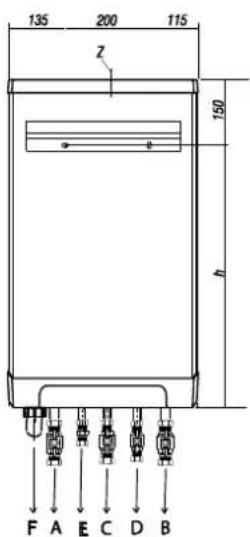
Appliance directly to the wall incl.
| A = | Flow CH | ∅22 (male) |
| B = | Return CH | ∅22 (male) |
| C = | Gas | ∅22 (male) |
| D = | DHW cold | ∅15 (male) |
| E = | DHW | ∅15 (male) |
| F = | Condensate | Condensate hose ∅25 flex |
| h = | 640mm | Rapid 25 |
| 700mm | Rapid 32 | |
| Z = | Flue gas outlet | ∅80 (seal) |
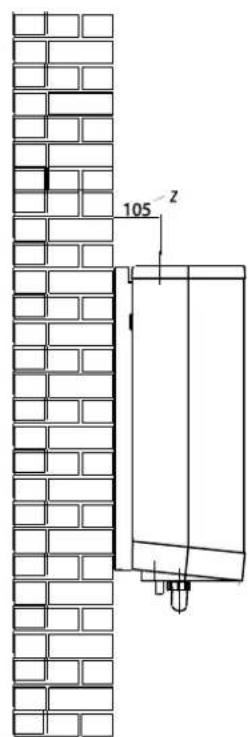
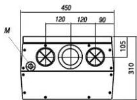

Appliance on wall mounting frame
| A = | Flow CH | ∅22 (male) |
| B = | Return CH | ∅22 (male) |
| C = | Gas | ∅22 (male) |
| D = | DHW cold | ∅15 (male) |
| E = | DHW | ∅15 (male) |
| F = | Condensate | Condensate hose ∅25 flex |
| h = | 640mm | Rapid 25 |
| 700mm | Rapid 32 | |
| Z = | Flue gas outlet | ∅80 (seal) |
6.2 Boiler location
The appliance can be fitted to a mounting frame. The assembly or just the appliance should be mounted to a wall with sufficient bearing strength. In case of light wall constructions, resonance sounds may occur.
If the boiler is to be installed in any room or compartment, it does not require any purpose made ventilation for combustion air. If sited in a room containing a bath or shower then particular reference is drawn to the current I.E.E.
Wiring Regulations, local Building Regulations or any other local regulations currently in service.
The boiler is not suitable for external installation unless protected by a purpose made building such as a boiler house.
The following clearances are recommended for installation purposes: 200 mm above, 300 mm below and 10 mm at each side. 500 mm is required at the front but this may be realized by opening a cupboard door.
Flammable fluids and materials must be stored at least 1 metre away from the boiler.
There must be an earthed electrical supply within a distance of 1 m from the appliance.
In order to avoid freezing of the condensate discharge, the appliance should be installed in a frost-free room.
Keep 5 cm free space above the appliance in order to be able to remove the front panel from the casing.
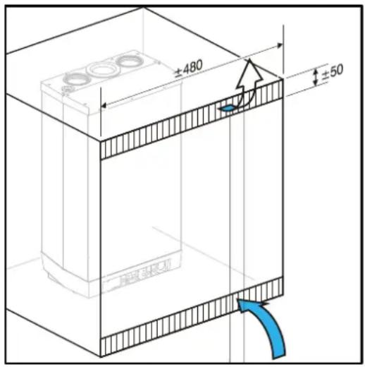
6.2.1 Installation in a kitchen cupboard
Make sure there is sufficient ventilation above and below the appliance. When the appliance is placed in a small cupboard, ventilation openings of at least 50 cm ^2 must be created at the top and bottom of appliance to ensure free flow of air.
6.2.2 Installation in an airing cupboard
Compartment ventilation is not required for a standard airing cupboard (eg 0.6 x 0.6 x 2.3m high).
6.2.3 Remove front panel
Remove the optional pipework cover and the front panel for carrying out work on the appliance as follows:-
- Remove the pipework cover (A), if used, forwards.
- Unscrew both screws (B) at the bottom of the appliance.
- Lift the front panel (C) and remove it forwards.

6.3 Assembly
Depending on the installation you can mount the boiler with either mounting bracket (included inside the boiler box) or the spacer frame (rear piping kit). Isolation valves pack included in the boiler box.
6.3.1 Fitting the mounting strip
- Fix the mounting bracket horizontally to the wall.
- Make sure the mounting bracket is level and secure before hanging the boiler.

natural_image
Technical line drawing of a metal bracket with screws and holes, no text or symbols present6.3.2 Fitting the spacer frame
When installing the boiler with a horizontal flue, you will need to use the spacer frame (rear piping kit) when the flue goes directly out the back of the boiler. This prevents the flue joint being in the wall.
- Fix the spacer frame vertically to the wall, using the fixings provided.
- Make sure the frame is level and secure before hanging the boiler.
Important:
The appliance is wider than the frame.

natural_image
Technical line drawing of a metal frame structure with mounting holes and bolts (no text or symbols)6.4 Mount the appliance
-
Unpack the appliance.
-
Check the content of the packaging. This consists of:-
-
Appliance (A)
- Mounting strip (B)
- Siphon cup (C)
- Flexible hose (D)
- Isolation valves
• Installation instructions -
Warranty card
-
Check the appliance for any damage: report damage to the supplier immediately.
-
Check when using a connection kit whether the compression rings are straight in the connectors.
-
Place the appliance: slide it top-down over the mounting strip.
-
The flexible tube from the condensate siphon should be inserted into an open waste pipe of not less than 32 mm diameter. If connected to a soil pipe or waste system, the waste pipe must include a trap (similar to arrangement for washing machine).
-
Tighten the compression fittings.
-
Mount the air supply and the flue discharge.
-
Mount the siphon cup (C) to the siphon connection at the bottom side of the boiler. Make sure the O-ring is placed correctly in the cup.
-
When needed the condensate outlet (behind the cup) can be extended using the flexible hose that has been delivered together with the boiler.
-
Fill the internal siphon by removing the hose coming from the PRV. Make sure the hose is placed again afterwards.

7. CONNECTIONS
7.1 Connect the CH system
- Flush the CH system thoroughly.
- Fit the flow (B) and return (A) pipes together with the shut-off valves to the boiler.
All pipes must be mounted tension-free in order to avoid ticking of the pipes. Existing connections inside the boiler must not be twisted in order to avoid leakages.
The CH system should be provided with:-
- A filling/draining tap in the return pipe immediately below the appliance.
- A drain tap at the lowest point(s) of the installation.

NOTE
The boiler is equipped with an internal pressure relieve valve
- A check valve, if pipes run upwards at a short distance from the appliance. This avoids the occurrence of thermosiphon effect during DHW operation mode.

7.1.1 Expansion vessel
The appliance is fitted with a expansion vessel adequate for a system with a water volume not exceeding 100 litres, typically 8 radiators. For larger volume systems, an additional expansion vessel must be fitted. Contact Intergas for advice in these cases.
7.1.2 Thermostatic radiator valves
If all radiators are equipped with thermostatic or regular radiator valves, a bypass must be fitted in order to guarantee minimum water circulation. The bypass must be at a distance of at least 6 m from the appliance in order to prevent overheating of the appliance.
7.1.3 Underfloor heating
For a good operation of the domestic hot water supply, there must be no undesired circulation through the appliance caused by a second pump of the CH circuit.
Connect underfloor heating with an electric shut-off valve (two-way valve) to prevent circulation through the appliance when there is no demand for central heating.
A. Boiler
B. Pump
C. Thermostatic control valve
D. Spring-operated non-return valve
E. Electrical shut-off valve 230 V \~
F. Radiators
G. Room/clock thermostat
H. Maximum thermostat
7.1.4 Weather compensation and heating DHW cylinder on hot water priority or W system
When connecting a Rapid to an indirectly heated DHW storage cylinder the following parts can be ordered:
• DHW storage cylinder sensor (art. nr. 065.117)
• Diverter valve 230V (art. nr. 092.647)
Connect the DHW storage cylinder and diverter valve according to the diagram. Remove the loop in 9 – 10 to connector X4. Connect the diverter valve to connector X2 and connect the DHW storage cylinder sensor or thermostat to connector X4 according to the electrical diagram (See chapter 13).
Electrical diagram indirectly heated DHW storage cylinder
C. Boiler
D. DHW storage cylinder
E. Radiator
F. Expansion vessel
G. Pressure relief valve 3 Bar
H. Diverter valve
I. DHW storage cylinder sensor or thermostat

flowchart
graph TD
    A["Component A"] -->|Flow| B["Valve B"]
    B --> C["Component C"]
    C --> D["Actuator F"]
    D --> E["Return Line"]
    E --> F["Feedback to A"]
    G["Control Unit G"] --> A
    H["Component H"] --> B
    I["Component I"] --> B
    J["Component J"] --> B
    K["Component K"] --> B
    L["Component L"] --> B
    M["Component M"] --> B
    N["Component N"] --> B
    O["Component O"] --> B
    P["Component P"] --> B
    Q["Component Q"] --> B
    R["Component R"] --> B
    S["Component S"] --> B
    T["Component T"] --> B
    U["Component U"] --> B
    V["Component V"] --> B
    W["Component W"] --> B
    X["Component X"] --> B
    Y["Component Y"] --> B
    Z["Component Z"] --> B
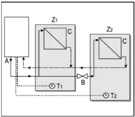
Appliance with zone control.
If there is, next to the CH system an other heating source (as for example a stove or a fireplace) in the living room often the problem occurs that the other rooms cool down.
This can be solved by splitting up the CH system into two separate zones.
The zone regulation can only be used when there is no external DHW tank present (in case of a system boiler)
Schedule zone-regulation
A. Appliance
B. Electrical Shut-off valve 230 V \~
C. Radiators
T1. Room thermostat zone 1
T2. Room thermostat zone 2
Z1. Zone 1
Z2. Zone 2
Operating principle
The zone regulation contains 2 room thermostats and a shut off valve. When the room thermostat of zone 2 generates a heat demand, the shut off valve opens and the complete CH system heats up (zone 1 and 2). When the heat demand of zone 2 is not or no longer present, room thermostat 1 controls the room temperature in zone 1.
Installation
- Place the shut-off valve into the heating system according to the schedule.
- Connect the room thermostat of zone 1 on to connector X4-6/7.
- Connect the room thermostat of zone 1 on to connector X4 - 11/12.
- Modify parameter A in the parameter list. (See § 9.3)
Note : The room thermostat for zone 1 must be an on/off type. The room thermostat for zone 2 can be either on/off or "Open Therm".
flowchart
graph TD
    A["Port A"] --> Z1["Zone Z1"]
    Z1 --> C["Zone C"]
    C --> T1["T1"]
    T1 --> B["Control Valve B"]
    B --> Z2["Zone Z2"]
    Z2 --> C["Zone C"]
    C --> T2["T2"]
    T2 --> B
    style Z1 fill:#f9f,stroke:#333
    style Z2 fill:#f9f,stroke:#333
7.2 Domestic hot water system
A. Flush the installation thoroughly to clean (please refer to current Standard Codes of Practice).
B. Fit the cold (A) and hot water (B) pipes together with the shut off valve and the press connection to the boiler.
Existing connections inside the boiler must not be twisted, in order to avoid leakages.
Make sure the compression fittings are tightened thoroughly to prevent leakage.
Notes
- If the appliance is only used for the provision of hot water, the heating function can be switched off by entering the service menu and change parameter 1.
The CH installation does not then have to be connected or filled.
- If the appliance is taken out of operation during the winter and disconnected from the mains supply, the DHW water must be drained in order to prevent freezing. For this purpose the DHW connections below the appliance must be removed.
Flow Resistance graph for appliance DHW circuit
A. Not applicable
B. Rapid 25
C. Rapid 32
X. pressure in bar
7.2.1 Appliance with solar water heater post-heating
The appliance carries the NZ label: suitable for "solar water heater post-heating". A special connection kit is applicable for this purpose.
Connection diagram for solar heater post -heating
A. Boiler
B. Storage tank Solar water heater
C. Cold water inlet
D. Inlet assembly
E. T max 85°C
F. Hot water outlet
G. Thermostatic mixing valve 40° - 90°C (set to approx. 55°C)
H. Mixed water outlet
Note
When combined with a solar power system a thermostatic mixing valve must always be fitted after the appliance and set to approx. 55°C.


line
| X | A | B | C | | ---- | --- | --- | --- | | 0.0 | 1 | 1 | 1 | | 0.2 | 3 | 4 | 4 | | 0.4 | 5 | 6 | 6 | | 0.6 | 7 | 8 | 8 | | 0.8 | 8 | 9 | 9 | | 1.0 | 8 | 10 | 10 | | 1.2 | 8 | 11 | 11 | | 1.4 | 8 | 12 | 12 | | 1.6 | 8 | 13 | 13 | | 1.8 | 8 | 14 | 14 | | 2.0 | 8 | 15 | 15 |
7.3 Electrical connection

CAUTION
An earthed wall socket must be located no more than 1 metre from the appliance.
The wall socket must be easily accessible.
For installation in damp rooms a fixed connection is obligatory.
When working on the electrical circuit always isolate the fuse spur and remove fuse.
If the mains lead has to be replaced, this should be carried out by the manufacturer
A. Unscrew screw (A) to gain access to the burner manager (B).
B. Pull the burner manager unit forwards; the burner manager will tip downwards to provide access.
C. Consult sections 7.3.1 and 11.5 for the making the connections.
D. After making the desired connections plug the appliance into an earthed wall socket.
7.3.1 Electrical connections
| Temperature control | Connector X4 | Notes |
| Room thermostat | 6 – 7 | Voltage free room thermostat.Remove link 6-7 |
| Outside temperature sensor | 8 – 9 | - |
| Frost protection thermostat | 6 – 7 | Parallel to room thermostat |
| Open Therm (OT) | 11 – 12 | Remove link 6-7 |
| Temperature control | Connector X2 | Notes |
| Room thermostat 230 V or external control 230 V | 1 – 3 | Remove link 6 – 7 (connector X4) |
| Frost thermostat 230 V | 1 – 3 | Remove link 6 – 7 (connector X4) |

7.3.2 On / Off room thermostat
To be connected to contacts 6 and 7 of connector X4.
This is a 24 volt connection and no mains power must be applied to these terminals.
See chapter 13, electrical diagram.
Note
When a 24 volt thermostat is connected to contacts 6 and 7, the loop in 6–7 must be removed
- The on/off room thermostat has to be connected to the contacts 6 and 7 of connector X4.
- The allowed maximum electrical resistance of the room thermostat and wiring is 15 Ohm.
7.3.3 Open Therm room thermostat
Open therm is a protocol that enables the boiler and the room thermostat to communicate. Based on the information from the room thermostat the flow temperature of the boiler is adjusted to the most optimal value.
The Open Therm (OT) room thermostat has to be connected to the contacts 11 and 12 of connector X4 (see chapter 13, electrical diagram).

CAUTION
Connecting the Open Therm room thermostat to other contacts than 11 – 12 may damage the room thermostat!

NOTE
When an Open Therm thermostat is connected to contacts 11 and 12, the loop in 6–7 must be removed.
7.3.4 Outside temperature sensor
The appliance is equipped with a connection for an outside temperature sensor. The outside temperature sensor can be used in combination with an on/off room thermostat or an OpenTherm thermostat.
Connect the outside temperature sensor (See § 8.3.1).
For the heating line setting, see weather-dependent regulation (See § 10.6). The sensor should be fitted where possible on a north facing wall.
7.3.5 230 volt room thermostat
To be connected to contacts 1 and 3 of connector X2.
See electrical diagram.

NOTE
When a 230V thermostat is connected, link in 6 - 7 of connector X4 must be removed
7.3.6 S and Y zone plans
Any combination of external controls for time /temperature and heating of external DHW cylinders or CH zones can be connected to the boiler.
All controls/ zones should be connected in an external wiring centre and a switched live connected to 1 on X2. Set in-built timer to C-ON.
Always remove link between 6-7 on X4 when fitting external temperature controls or the boiler will run constantly

Warning High Voltage
Isolate the appliance from the electrical supply before connecting the thermostat.
7.4 Condensate disposal
The appliance is provided with a 25 mm flexible pipe from its condensate trap. Connect the flexible tube from the condensate trap to the drain via an open connection.

CAUTION
Always fill the condensate trap with water and place it on the boiler before powering up the boiler.
For filling the condensate trap the hose between de trap and the PRV has to be removed (trap side). Make sure the hose is re-mounted after filling the condensate trap.
Not placing or filling up the condensate trap may cause flue gases to come into the installation room and can lead to dangerous situations!
The condensate discharge system, pipework and fittings must be made of plastic. No other materials may be used. The discharge duct must have a gradient of 5 – 20 mm/m throughout its length. Condensate discharge via the gutter is not allowed given the risk of frost and the possible damage to materials
a. Internal stack pipe (see diagram)
b. Gully
c. Condensate discharge from boiler
d. Serviceable waste trap
e. 5 - 20 mm/meter
f. > 100 mm
g. > 110 mm
h. > 450 mm
If an externally-run condensate drainage pipe is used the following measures should be adopted to prevent freezing:
- the pipe should be run internally as far as possible before going externally, the pipe diameter should be increased to a minimum of 30mm ID (typically 32mm OD) before it passes though the wall;
- the external run should be kept as short as possible, taking the most vertical route possible to the discharge point, with no horizontal sections in which condensate might collect;
- the external pipe should be insulated using suitable waterproof and weatherproof insulation ("Class O" pipe insulation is suitable for this purpose);
- the use of fittings, elbows etc should be kept to a minimum as any internal "burrs" on cut pipework should be removed so that the internal pipe section is as smooth as possible.
For more information about preventive measures against freezing please visit the HHIC website http://www.centralheating.co.uk/checklists/frozen-condensate-pipes.


7.5 Gas connection
- Fit the gas isolation valve (A) between the gas supply and the appliance.
- Fit the connection from the gas tap preferably directly into the 12 "connection at the mounting bracket.
- Install a gas filter mesh in the connection for the appliance if the gas may be contaminated.
- Connect the appliance to the gas supply.
- Check the gas carrying parts for leakage.

natural_image
Technical diagram of a mechanical assembly with multiple pressure vessels and a blue component labeled 'A' (no text or symbols beyond label)7.6 Flue system
7.6.1 General
- The boiler is prepared to be connected to a concentric flue system 60/100.
- The flue system must be connected to the flue adapter of the boiler. The internal seals ensure the air tightness of the connection.
- By replacing the standard adapter for a flue adapter 80mm and removing the plastic cap from the air inlet in the top of the boiler, the boiler can be made suitable for connecting to a 80/80 twin flue system
Explanation flue system category
| Category | Explanation |
| C13 | The terminal is located in the façade; the inlet for the air supply duct is located in the same pressure area as the terminal.Example: combined wall terminal |
| C33 | The terminal is located above the roof; the inlet for the air supply duct is located in the same pressure area as the terminal of the flue piping. |
| C53 | Closed unit, connected to separate air supply duct and flue pipes, terminated in various pressure zones. |
Draft, materials and insulation
| Flue type | Diameter | Material |
| Concentric | 60/100 | Aluminium, Stainless steel of PP (T120) |
| Air inlet | 80 mm | According to (local) regulations of the fire department and/or energy supply company.Approved material incl. seals- Aluminium- Plate steel (galvanised)- Stainless steel- Plastic.N.B. Rain water drainage pipes are not allowed |
| Flue gas | 80 mm | - Aluminium in accordance to EN 1856-1 of EN 1856-2- Plastic in accordance to EN 14471N.B. Temperature class T120 |
| Insulation | - | 10 mm vapour-tight insolation material.Applicable when risk on condensation on the outside is present. |
7.6.2 Sealed flue system.
Concentric connection.
A. Mount the concentric flue pipe in the flue adapter of the boiler. The integrated seal will secure an air-tight connection.
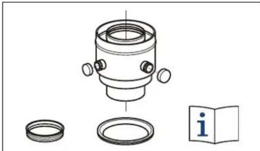
7.6.3 Flue pipe and air supply
For connecting the boiler to a concentric flue system a special concentric flue adapter has to be used. An adapter for connecting to a 60/100 flue system can be ordered at Intergas Heating Ltd. See chapter 5.2, Flues.
Note
Only use approved Intergas flue products with this boiler, which can be sourced from the supplier of your boiler or Intergas stocklist.
natural_image
Technical line drawing of a mechanical assembly with no visible text or symbols| Terminal Position | Min. distance | |
| A | Directly below an open able window or other opening e.g. air brick | 300 mm |
| B | Below gutters, soil pipes or drain pipes can be reduced to 25mm, as long as the flue terminal is extended to clear any overhang. External flue joints must be sealed with suitable silicon seal. | 25 mm |
| C | Below eaves | 200 mm |
| D | Below balconies or car front roofs | 200 mm |
| E | From vertical drain pipes and soil pip | 25 mm |
| F | From internal or external corners | 300 mm |
| G | Above ground, roof or balcony level, Terminal guards must be fitted if less than 2 metres from the ground. | 300 mm |
| H | From a surface facing a terminal | 600 mm |
| I | From a terminal discharging towards another terminal | 1200 mm |
| J | From an opening in a car port (e.g. door, window) into a dwelling | 1200 mm |
| K | Vertically from a terminal on the same wall | 1500 mm |
| L | Horizontally from a terminal on the same wall | 300 mm |
| M | Above an opening, air brick, opening windows, etc. | 300 mm |
| N | Horizontally to an opening, air brick, opening windows, etc. | 300 mm |
| P | Above roof level (to base of terminal) | 300 mm |
| Q | From adjacent wall to flue | 300 mm |
| R | From an adjacent opening window | 1000 mm |
| S | From another roof terminal | 600 mm |
| - | From an external boundary. Note: if the terminal is facing a boundary it is recommended that an anti-plume kit be fitted. | 600 mm |
| T | Terminals adjacent to windows or openings on pitched and flat roofs: The flue should not penetrate this area. | 2000 mm |
| T1 | 600 mm | |
| T2 |


Note
Intergas cannot be held responsible for atmospheric conditions when siting flue terminals

CAUTION
Once the flue has been installed and the appliance commissioned, installer should observe the plume direction.
Particular attention should be drawn to plume vapour re-entering the boiler via the air intake. If this occurs, it is highly possible the flue is fitted within a negative pressure area and therefore a plume management kit (PMK) must be fitted.
7.6.4 Length flue pipe and air inlet when connecting to a concentric flue system
Concentric ∅60/100
| C13 | C33 | |
| Intergas Rapid 25 | 10 m | 11 m |
| Intergas Rapid 32 | 10 m | 10 m |
Replacement lengths
| Curve 90° | R/D=1 | 2 m |
| Curve 45° | R/D=1 | 1 m |
| Knee 90° | R/D=0,5 | 4 m |
| Knee 45° | R/D=0,5 | 2 m |
7.6.5 Horizontal flue system
The 60/100 mm horizontal flue system may be extended up to a maximum length as mentioned in the table above.
The wall terminal must be installed horizontally.
CAUTION

Only an Intergas approved flue is to be used with this product. Failure to comply with this requirement will invalidate your guarantee and may lead to a dangerous situation!
The horizontal wall terminal must be installed level as the flue terminal already has a 3 degree rise built in. If the use of flue extensions are needed then they must be fitted with a 3 degree fall back to the boiler and have a bracket fitted ever meter to support the flue. Best recommended position of the bracket is just before the joint.
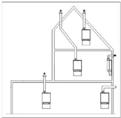
7.6.6 Vertical flue system
The 60/100 mm vertical flue system may be extended up to a maximum length as mentioned in the table above. The vertical flue system contains a flue adapter concentric 60/100 to replace the standard adapter on the boiler.
Please note that the terminal is suitable for a flat or pitched roof and only approved Intergas flue products can be used with this boiler.
natural_image
Pure schematic diagram of a multi-level industrial or hydraulic system with no text, numbers, or symbols
natural_image
Pure electrical circuit lines without any symbols
natural_image
Technical line drawing of a mechanical component with no visible text or symbols
natural_image
Technical line drawing of a mechanical component with no visible text or symbols
CAUTION
Only an Intergas approved flue is to be used with this product. Failure to comply with this requirement will invalidate your warranty and may lead to a dangerous situation!
7.6.7 Plume management kit
The plume management kit comprises of a 710 mm horizontal section with elbow to connect the 1m vertical condensing tube, which has a horizontal or vertical terminal dependent on your requirements. The maximum length of horizontal flue including the terminal but excluding the initial elbow from the boiler and 1 metres vertical condensing tube is 7 metres.
Note
For each additional 90^ elbow used the maximum flue length must be reduced by 1.5 metres, whilst the use of 2 × 45^ bends warrants a reduction of 2 metres.
The horizontal part of the flue must be installed under a 3^ fall towards the boiler (50 mm per metres) and must be supported with a minimum of 1 bracket at each meter length. Best recommended position of the bracket is just before the joint.

CAUTION
- Sealing rings should only be moisturized with water before use. Do not use soap or other detergents.
- When installing flues in voids make sure they are connected and fixed correctly. If in an existing situation a visual inspection is not possible the boiler must not be commissioned and remain disconnected from the gas supply until suitable access has been realised.
- Make sure to follow the manufacturer's instructions regarding maximum length of the flue system, the appropriate flue material, correct jointing methods and the maximum distance between flue support.
- Ensure that all joints and seams are gastight and watertight.
- Ensure the flue system has a uniform gradient back to the boiler.
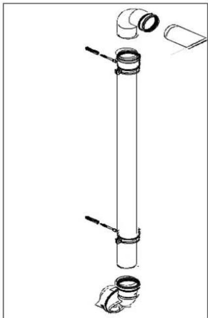
7.6.8 Flues in voids
The flue system must be connected in accordance with the manufacturers instructions BEFORE firing the boiler.
The term void includes ceiling voids, floor voids, purpose built enclosures, service risers, roof spaces or any other enclosure that will restrict access to inspect the flue.
To allow visual inspection, without reliance on devices such as endoscopes, cameras and mirrors, inspection hatches must be provided along the entire length of the flue.
Hatches must be a minimum of 300mm x 300mm and positioned with the edge of the inspection hatch to 1.5m of any joint and at changes of direction. Bends should be viewable from both directions where the inspection hatch cannot be positioned at the bend.
Where suitable access is not provided the appliance MUST NOT be commissioned and must be disconnected from the gas supply.
Additionally the entire flue and all flue seals must be installed in accordance with the requirements of BS5440:
- Check condensate trap is filled with water and correctly connected to boiler.
- All flue joints are correctly made, unstressed and adequately supported.
- All parts of the flue can be visually inspected -ensure suitable access where flue is positioned within voids-
natural_image
Technical line drawing of a vertical pipe assembly with multiple components (no text or labels)Concealed Flue Joints:
Acceptable Installations:
Telescopic Flue & terminal: The telescopic overlap in Intergas horizontal flue is not considered as a flue joint. The flue section must be adjusted to the correct length then the telescopic joint must be secured and sealed with the screw and tape provided in line with manufacturers instructions. It is acceptable for this secured, sealed overlapping connection to be sited within the building fabric.
Non-acceptable Installations
Flue Extensions & Elbows: Flue joints between flue extensions & elbows must not be sited within the building fabric. Where necessary flue extensions should be cut to suit to avoid this.
Flue Integrity:
The flue should be inspected under its annual service and at the initial commissioning of the appliance to confirm:
• All joints in the flue system are sound and correctly assembled according to manufacturers instructions.
• The flue is continuous without any breaks.
• All flue joints should be visible for visual inspection.
• Checked by means of sampling the air intake at the flue air intake sample point with a calibrated flue gas analyser.
• All voids containing concealed flues should have inspection hatch measuring no less 300mm square.
(Ref TB 008Ed3)
7.6.9 Free in the market available flue systems (C63)
The properties of the gas combustion of the appliance determine the choice of the air inlet and flue material: temperature, pressure, chemical composition, condensation and the presence of soot.
The standards NBN EN 1443 and NBN EN 1856-1 provide for the classification of the air inlet and flue material according to their resistance to these elements due to different class indications. This marking of the flue gas discharge channels is shown in the form of a code on the flue gas discharge and clarified in the NBN B61-002.
These classes, supplemented with information about the minimum wall thickness, offer the maximum permitted leak rate and the requirements regarding fire safety, the possibility to make the right choice for the connections to be used flue material in the function of the type of gas appliance and in function of the application.
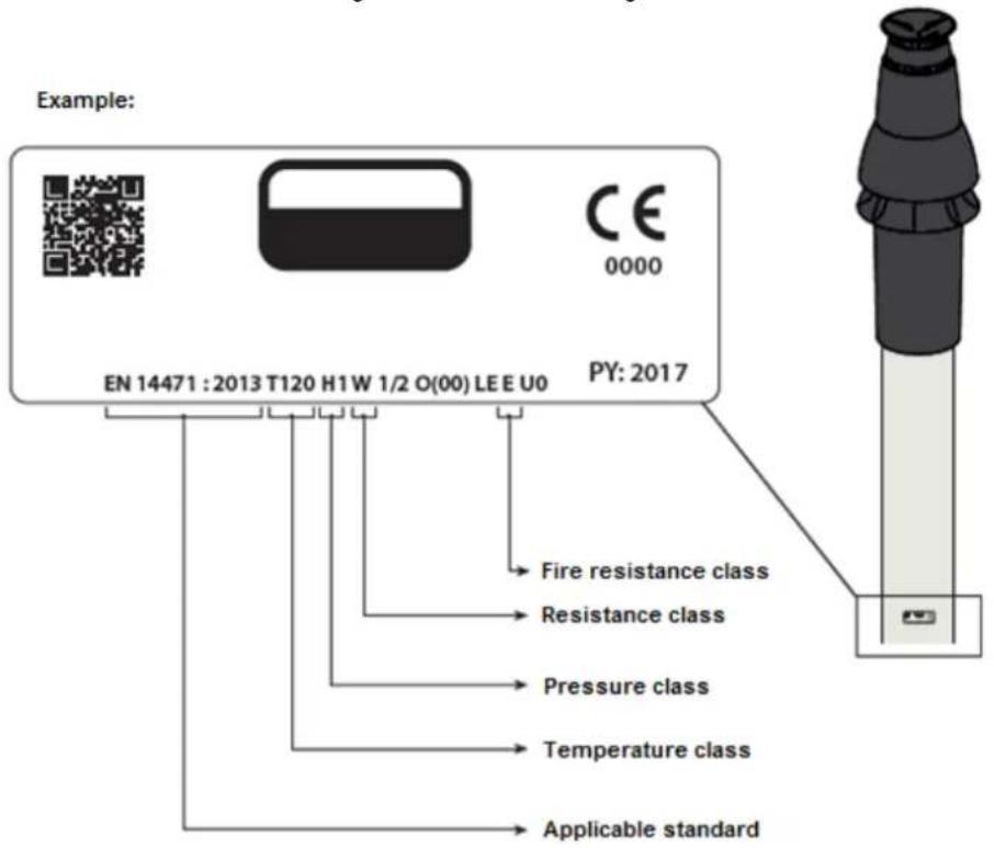
Flue gas materials connected to the boiler models need to comply to the following minimal demands (shown in the marking)
- CE marking:
• The for the material applicable standard: - Temperature class:
- Pressure class:
• Resistance class of condensate
• Euro-fire resistance class according to EN 13501-1:
With the exception of wall terminals. For wall terminals category C13 applies For aluminium and stainless steel EN 1856-2 applies, For plastic the standard EN 14471 applies.
T120 for plastic flue material.
Overpressure (P) or high overpressure (H).
W (wet condensates)
E or higher
7.6.10 Dimensions Flue gas materials:
| Parallel | Concentric 80/125 | Concentric 60/100 | |||
| Flue pipe | Air inlet | Flue pipe | Air inlet | ||
| 80 | +0,3-0,7 | 80 | +0,3-0,7 | 60 | +0,3-0,7 |

IMPORTANT
Flue parts of different producers are not to be combined!
7.6.11 Securing the flue system

IMPORTANT
- These regulations are typical for both concentric and Twin flue flue systems.
• The flue system must be secured to a solid structure. - The flue system should have a continuous fall back to the boiler (1.5° to 3°). N.B. Wall terminals must be installed leveled..
- Only use accompanying brackets.
- Every elbow must be secured by using the bracket. Exception at connecting on boiler: If the length of the pipes before and after the first elbow, are no more than 250 mm, the second element after the first elbow has to contain a bracket. Note: The bracket must be positioned on the elbow!
- Every extension must be secured per metre with a bracket. This bracket must not be clamped around the pipe ensuring free movement of the pipe..
- Make sure bracket is locked into the correct position depending on the position of the bracket on the pipe or elbow:
- Do not mix flue parts or clamps of different suppliers.

Max. distance between clamps
| Vertical | Others |
| 2000 mm | 1000 mm |
• Divide the lengths between the brackets evenly.
- Every system must contain at least 1 bracket.
- Position the first clam at a maximum of 500 mm from the boiler.


First clamp after second elbow
8. COMMISSIONING
8.1.1 Fill and de-aerate the appliance and the system

WARNING
Connect the appliance to the mains voltage only after filling and de-aerating!
8.1.1 CH system

WARNING
When an additive is added to the CH water, this should be suitable for the materials used in the appliance, such as copper, brass, stainless steel, steel, plastic and rubber.
- Fill the system to a maximum pressure of 1 to 2 bar with a cold system.
- Vent the appliance with the manual air vent (A).
- Vent the system with the manual air vents on the radiators.
- Fill up the CH system when the pressure has dropped too low as a result of the de-aerating.
- Check all joints for leaks.
- Fill the siphon with water. See § 7.4 for the filling procedure.

natural_image
Technical line drawing of a mechanical assembly with a blue bolt and concentric rings (no text or symbols)8.1.2 Hot water supply
- Open the main tap in order to pressurise the hot water part.
- De-aerate the heat exchanger and the pipe system by opening a hot water tap. Leave the tap open until all the air has left the system.
- Check all joints for leaks.
8.1.3 Gas supply
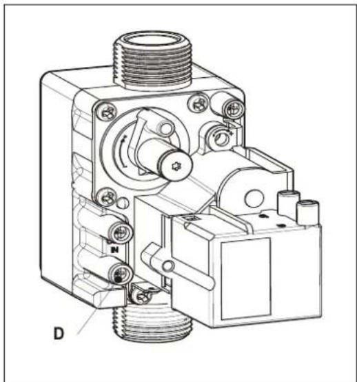
A. Gas supply purged of air via test point D on gas valve (see illustration)
B. Connect a suitable gauge to test point D.
Static or standing pressure must be 20mBar.
If 20mBar is not obtained DO NOT proceed with commissioning until supply is rectified.
C. If static pressure is correct fire the boiler and allow to reach working temperature.
D. Test working pressure by selecting test program "H". See section 10.8, High Setting. Working pressure must be 20 mBar + or- 1 mBar. If working pressure is less than 19mBar the appliance heat output will be reduced and correct combustion readings may not be obtained. Do not adjust the air/gas ratio. Correct gas supply to obtain sufficient working pressure.
Note. The inlet working pressure must be obtained with all other gas appliances at the property working.

NOTE
The inlet working pressure must be obtained with all other gas appliances at the property working.
A. Please refer to the Benchmark commissioning Checklist on page 66

natural_image
Technical line drawing of a mechanical device with threaded shaft and mounting base (no text or symbols)Combustion
The combustion for this appliance has been checked, adjusted and preset at the factory for operation on the gas type defined on the appliance data plate. Do not adjust the air/gas ratio valve. Having checked:
- That the boiler has been installed in accordance with these instructions;
- The integrity of the flue system and the flue seal, as described in § 5 and the British Standards codes of practices, specifically BS 5440;
-
The integrity of the boiler combustion circuit and the relevant seals, as described in § 0 eg with a flue spillage mirror; proceed to put the boiler into operation as follows:
-
Set up the boiler to operate at maximum rate as described in
- With the boiler operating in the maximum rate condition check that the CO₂ value measured at the sampling point off the flue adapter complies with the requirements as described in the § 9.8
Ensure that this inlet pressure can be obtained with all other gas appliances in the property working.
8.1.4 Flue system
The flue system must be connected correctly to the appliance in accordance with the manufacturer's instructions. The flue termination should also be checked. Where suitable access for a visual inspection of an existing flue system has not been provided the appliance must not be commissioned and it must be disconnected from the gas supply.
8.2 Commissioning of the appliance

Read-out
1 On / off
2 CH operation or setting maximum CH temperature
3 DHW operation or setting DHW temperature
4 Desired temperature of CH or DHW in °C / Ch water pressure (bar) / Fault code/ Time
5 Clock "on" CH enabled
6 Clock "off" CH disabled
7 DHW comfort function eco
8 DHW comfort function on (continuous)
9 Operating code
10 Flashes to indicate fault
Operation
A On / Off button
B DHW / CH button, for setting desired temperature
C - button
D + button
E Clock function setting
F DHW comfort function off / eco / on
G Service button
H Reset button
2.
Once the preceding actions have been carried out, the appliance may be started up.
- Press the Ⓐ button, to start the appliance.
The heat exchanger is heated up and the service ✏ display will show 3, 4 and 5 (depending on the status of the DHW disabling switch and/or Open Therm regulation).
- Adjust the pump setting depending on the maximum power set and the resistance in the CH installation. For the water head of the pump and the pressure loss of the appliance see § 10.5.
- Set the room thermostat higher than the room temperature. The appliance will now switch to CH operation: 5 will show on the display.
- Heat the installation and the appliance to approximately 80°C.
- Check the temperature difference between the supply and return for the appliance and the radiators. This must be approximately 20^ C. For this purpose set the maximum power on the service panel. See setting maximum power. If necessary adjust the pump setting and/or the radiator valves. For the minimum flow see § 10.5.
- Switch the appliance off.
- Bleed the appliance and the installation after cooling (if necessary top up).
- Check correct operation of the heating and hot water supply.
- Instruct the user on filling, bleeding and the operation of the clock, heating and hot water supply. For setting the clock see § 9.3.
Notes
- The appliance is equipped with an electronic boiler controller, which ignites the burner and continuously monitors the flame during each request for heat from the heating or from the hot water supply.
- The circulation pump starts running in response to every request for heat. The pump continues running for 1 minute after heating. This post purge period can be changed if desired (See § 10.3).
- The pump runs automatically for 10 seconds every 24 hours in order to prevent seizing. This will occur at the time of the last request for heat. To change this time the room thermostat should be turned up briefly at the desired time.
• The pump does not run during DHW operation.
8.3 Setting and adjusting the clock functions
8.3.1 Setting the clock
- Press the ⏻ button for less than 1 second and repeat this until “24hr clock” appears. For adjusting the clock to the correct time press the [+] or [-] button. Note: Holding the button for more than 1 second will make the clock run fast.
8.3.2 Setting the timer function
- On pressing the ⏻ button for more than 2 seconds the clock display will flash.
• The time for each on/off shows in the clock display and the service display shows which on 1 and 3 OR off 2 and 4 time is being set. - Pressing the ⏻ button again will change between the different on/off switching periods.
The pre-set times are as follows:
Display : [06:00] and [1] → Start first period CH on.
[09:00] and [2] → End first period CH off.
[16:00] and [3] → Start second period CH on.
[22:00] and [4] → End second period CH off.
- By pressing the ↻ button the new times will be stored in the boiler controller. In the service display [P] appears.
- When the clock is in period [1] or [3] (CH ON) the clock symbol LED is on.
- When the clock is in period [2] or [4] (CH not active) the ① LED is on.
- By pressing the ⏻ button over 5 seconds the default setting for the switch moments will be restored.
In the service display "F-set" appears.
- By pressing the ① button the boiler controller will return to the normal situation without storing any changes.
8.4 Additional functions
- Pressing the Ⓧ button for less than 1 second the following additional functions can be activated: - t-on (temporary on).
The boiler will respond on every CH demand from the room thermostat until the next switch moment.
- c-on (continuous on).
The boiler will respond on every CH demand from the room thermostat without any time limit.
- OFF
The boiler will not respond on any CH demand from the room thermostat.
8.5 Shutting down

CAUTION
Drain the appliance and the installation if mains power has been interrupted and there is a possibility of freezing.
- Drain the appliance at the drain tap.
- Drain the installation at the lowest point.
- Close the main cock for the water supply to the DHW section.
- Drain the appliance by removing the DHW couplings below the appliance.
8.5.1 Frost protection
- To avoid freezing of the condensate drain pipe the appliance must be installed in a frost-free area.
- To avoid freezing of the appliance it is equipped with frost protection. If the temperature of the heat exchanger becomes too low, the burner switches on until the temperature of the heat exchanger is sufficient. If there is a possibility of the installation (or part of it) freezing, an (external) frost thermostat must be installed at the coldest point of the return pipe. This must be connected in accordance with the wiring diagram (See chapter 13).
Note
If an (external) frost thermostat has been fitted to the installation and connected to the appliance, this will not be active when the appliance is switched off at the operating panel (- on service display).
8.6 System Shutdown
CAUTION
Drain the appliance and the system when the mains voltage has been disconnected and there is a chance of freezing.
- Drain the appliance using the filling/drain tap.
- Drain the system at the lowest point.
- Close the main valve for the cold water supply to the boiler.
- Drain the appliance by disconnecting the domestic hot water connections underneath the appliance or opening hot water taps.
8.6.1 Frost protection
- In order to avoid freezing of the condensate discharge pipe, the appliance should be installed in a frost-free room.
- In order to avoid freezing of the appliance (heat exchanger), it has an appliance frost protection. When the temperature of the heat exchanger drops to 5°C, the burner will be activated and the pump will start running until the temperature of the heat exchanger reaches 10°C.
- When the system (or a part thereof) can freeze, a frost thermostat should be installed in the area to be protected. Connect this according to the wiring diagram. See § 11.5.
Note!
The external frost thermostat is not active when the appliance has been switched off at the operating panel or when the mains voltage has been interrupted.
9. SETTING AND ADJUSTMENT
The functioning of the appliance is determined primarily by the (parameter) settings in the boiler controller. Part of this can be set directly via the operating panel; another part can only be adjusted using the installer code.
9.1 Directly via the operating panel
The following functions can be operated directly:
9.1.1 Appliance on/off
The appliance is started using the Ⓛkey.
When the appliance is in operation the green LED above the ⓚkey will light up. When the appliance is off a single dash lights up on the service display (☐-) to indicate that supply voltage is present. In this mode the pressure in the CH installation (in bar) can also be read on the main display.
9.1.2 DHW comfort
The 'DHW comfort function' can be operated with the DHW comfort key and has the following settings:
On: (① LED on) The appliance's DHW comfort function is switched on continuously. In this mode the heat exchanger will be kept on temperature to assure instant delivery of hot water.
- Eco: (LED on) The standard setting of the appliance's DHW comfort function is self-learning. The appliance will adapt to the pattern of use of hot tap water. As a result, the temperature of the heat exchanger will not be maintained during the night or in the case of long absence.
The number of Eco days can be set with parameter o. See also chapter 9.3 It is also possible to control the keep hot facility by using a mechanical switch of by the Open Therm room thermostat. See chapter 9.3.1
- Off: (Both LEDs off) The temperature of the heat exchanger is not maintained, as a result of which the delivery of hot tap water takes a little time. If there is no need for hot tap water or its immediate delivery, the DHW comfort function can be switched off.
9.1.3 Resetting
When a lock-out is indicated by means of a flashing LED above the ☑ key and a code on the main display, the appliance can be restarted by pressing the ☑ key. Check the nature of the fault on the basis of the fault codes in § 11.1 and resolve the cause of the fault if possible before resetting the appliance.
9.1.4 Changing the settings of the various functions:
Holding the ⚫ key pressed in for 2 seconds takes you to the user settings menu(LED at 📄 and the figure display start to flash). Pressing the ⚫ key repeatedly results in a different function LED flashing each time. When the LED is flashing the indicated function can be set with the + and — key . The value set is shown on the ⚫ display.
The ① on/off key closes the settings menu without storing the changes.
The reset ↩ key closes the settings menu and the changes are stored.
If no key is pressed during a period of 30 seconds, the settings menu is closed automatically and the changes are stored.
9.1.5 Maximum CH supply temperature
Press the 🔒 key until the LED at starts to flash.
With the + and — key s set the temperature between 30^ C and 90^ C (default value 80^ C).
Press the ⚠ key until the LED at ⚡ starts to flash.
With the + and - keys set the temperature between 40°C and 65°C (default value 55°C).

9.2 Settings through the service code
The burner controller of the appliance has been set in the factory according to the parameters of §
9.3. These parameters can only be changed with the service code. Proceed as follows to activate the program memory:-
-
Set the appliance in the off mode using the On/Off key ( - on the service display).
-
Simultaneously press the Service and Reset keys, until a ☐ appears on the service and the temperature displays.
-
Using the “+” and “-” keys, set 15 (service code) on the temperature display.
-
Press the "Service" key to confirm the code and enter the desired parameter.
-
Set using the "Service" key the parameter to be set on the service display.
-
Set using the "+" and "-" keys the parameter to the required value on the temperature display.
-
After having entered all required changes, press the "Reset" key until P appears on the service display.
-
Switch on the appliance again using the "On/Off" key.
The burner controller has now been reprogrammed.
9.3 Parameters
| Parameter | Setting | Factory setting | Description | |
| Rapid 25 | Rapid 32 | |||
| 0 | Service code [15] | - | - | Access to installer settings. The service code must be entered (=15). |
| 1 | System type | 0 | 0 | 0 = standard1 = heating only operation + indirect hot water tank2 = hot water only operation3 = heating only operation |
| 2 | CH pump continuous | 0 | 0 | 0 = pump overrun only1 = pump continuously active2 = n/a |
| 3 | Setting CH power | 70 | 70 | Setting maximum CH loadSetting range : value par. c - 90 % (Rapid 25)Value par. c - 100 % (Rapid 32) |
| 3. | Max. power for modulating pump | 80 | 80 | Setting range : value of parameter c. until 100 |
| 4 | Setting DHW power | 99 | 99 | Setting maximum DHW power |
| 5 | Min. supply temperature of the heating curve | 25 | 25 | Setting range 10°C to 25°C (Weather-dependent control) |
| 5. | Max. value for the flow temperature to be set in the display | 80 | 80 | Setting range 30 - 90 °C |
| 6 | Min. outside temperature of the heating curve | -7 | -7 | Setting range -9°C to 10°C (Weather-dependent control) |
| 7 | Max. outside temperature of the heating curve | 25 | 25 | Setting range 15°C to 30°C (Weather-dependent control) |
| 8 | CH pump overrun time after CH operation | 1 | 1 | Setting range 0 - 15 minutes |
| 9 | CH pump overrun time after heating external DHW tank | 1 | 1 | Setting range 0 - 15 minutes (n/a) |
| A | Position 3-way or 2-way valve | 0 | 0 | 0 = confirmed during CH operation (n/a)1 = confirmed during hw operation (n/a)2 and higher = not applicable |
| b | Booster | 0 | 0 | Not applicable. |
| C | Step modulation | 1 | 1 | 0 = step modulation off during CH operation1 = step modulation on during CH operation2 = CH Output controlled by OT controller |
| c | Minimum speed/output CH | 25 | 25 | Setting range 25 to 40% |
| c. | Minimum power modulating pump | 40 | 40 | Setting range : 15 - value of parameter 3. |
| d | Minimum speed/ output DHW | 25 | 25 | Setting range 25 to 40% |
| E | Min. supply temperature during OT demand(OT = OpenTherm stat) | 40 | 40 | Setting range 10°C to 60°C. If the OT thermostat demands a supply temperature that is below this set value, the heat demand cannot be met. |
| E. | OT reaction | 1 | 1 | 0 = Ignore OT demand if the setpoint for the flow temperature (value send by controller) is below the value of par E1 = Accept OT demand if the setpoint for the flow temperature is below the value of par E.The setpoint for the flow temperature is the value of par. E2 = Disable OT (heat demands will be accepted with a flow temperature as set in the display) |
| F | Starting speed CH | 60 | 50 | Setting range 50 to 99% |
| F. | Starting speed DHW | 60 | 50 | Setting range 50 to 99% |
| H | Max. fan speed | 45 | 45 | Setting range 40 to 50 (40 = 4000 rpm, 50 = 5000 rpm) The absolute maximum speed can be set through this parameter. |
| L | Legionella prevention(only applicable when using external tank and W-plan) | 0 | 0 | 0 = Legionella prevention disabled.1 = Legionella prevention weekly2 = Legionella prevention daily |
| n | Flow temperature during heating DHW cylinder | 85 | 85 | Setting range 60°C to 90°C |
| n. | Eco/Comfort DHW temperature(keep hot facility) | 0 | 0 | Setting range 0, 40 – 65 °C0 = temperature is equal to DHW temperature setting40 – 65 = absolute temperature |
| O. | Delay time CH | 0 | 0 | Setting range 0 = 15 minutes |
| o | Delay time CH after DHW | 0 | 0 | Setting range 0 – 15 minutes. |
| o. | Eco Days | 3 | 3 | Setting range : 0 – 100 = Keep hot facility controlled by Open therm room thermostat1 – 10 eco days. |
| P | Minimum switch off time during CH operation | 5 | 5 | Setting range 0 to 10 minutes (anti cycling function) |
| P. | DHW coefficient | 30 | 36 | Setting range 0, 24, 30, 300 = Applicable for combi boilers with flow switch24 = not applicable30 = Rapid 2536 = Rapid 32 |
| q | Summer mode | 0 | 0 | Not applicable |
| r | Heating curve coefficient | 0 | 0 | Not applicable. |
9.3.1 Enable/disable keep hot facility by Open Therm room thermostat.
It is possible to enable and disable the keep hot facility of the boiler by using an Open Therm room thermostat. For this the boiler needs to be set in Eco mode: ( ⊙ LED on).
Also the parameter o. needs to be set to 0. In this setting the adaptive behaviour of the boiler (see § 9.1.2) is disabled.
The Open Therm room thermostat will now enable or disable the keep hot facility (provided that the room thermostat supports this function)
9.4 Setting maximum CH power
The maximum CH power is set to 70% in the factory. When the CH system requires more or less power, the maximum CH power can be changed by adjusting the fan speed. See table: Setting CH power.
This table gives the relation between the fan speed and the appliance power.
Setting CH power
| Required CH power (approx. in kW) | Setting on service display (% of the maximum speed) | |
| Rapid 25 | Rapid 32 | |
| 22.6 | 26.2 | ± 83 |
| 19.1 | 22.0 | 70 |
| 16.4 | 19.0 | 60 |
| 13.7 | 15.9 | 50 |
| 11.0 | 12.7 | 40 |
| 8.3 | 9.6 | 30 |
| 6.9 | 7.0 | 25 |
Caution
The power slowly increases while burning (modulation by time) and decreases as soon as the set supply temperature is reached.
9.5 Setting pump position
- Adjust the pump setting dependent on the maximum power set and the water resistance of the installation by setting the parameters 3. (3 dot) and c. (c dot).
The pump speed will now modulate between the minimum and maximum value proportional to the fan speed.
- Check the temperature difference between the appliance supply and return: this must be approximately 20^ C.
Make sure the flow does not undershoot the values mentioned in the table below.
| The minimum flow-through | Set power |
| 200 l/h | 7.0 kW |
| 750 l/h | 26.2 kW |
A. Not applicable
B. Rapid 25
C. Rapid 32
X Flow-through in litres/hr
Y Pressure loss / pump lift in metres head
9.6 Weather-dependent control
When the outside sensor is connected, the supply temperature is automatically controlled dependent on the outside temperature in accordance with the set control line.
The T set CH (= CH supply temperature) is set via the temperature display. If required, the control line can be adjusted by the service code. See § 9.3.
X. T outside °C A Factory setting
Y. T supply °C B Example

natural_image
Technical line drawing of a mechanical device with threaded ports and a control panel (no text or symbols)Press loss/pump lift (m head)

Flow (litres/hr)

line
| X | Y | |---|---| | -10 | 80 | | -10 | 60 | | 25 | 25 | | 30 | 25 |9.7 Conversion to different gas type

CAUTION
Work on gas carrying parts may only be carried out by a qualified competent person.
If a different type of gas is connected to the appliance than that for which the appliance has been set by the manufacturer, the gas metering ring should be replaced. Conversion sets for other types of gas are available to order.
1.1.1 Converting the gas restriction.
E. Switch the boiler off and isolate the boiler from the mains power.
F. Close the gas isolation valve.
G. Remove the front panel from the appliance.
H. Unscrew the coupling (A) above the gas valve and twist the gas mixing tube towards the rear (B).
I. Replace the O-ring (C) and the gas restriction (D) with the rings from the conversion set.
J. Re-assemble in reverse sequence.
K. Open the gas isolation valve.
L. Check the gas connections before the gas valve for gas-tightness.
M. Switch on the mains power.
N. Check the gas connections after the gas valve for gas-tightness (during operation).
O. Now check the setting of the CO_2 percentage at high setting (H in display) and low setting (L in display).

CAUTION
It is not possible to adjust the CO_2 percentage at high setting. When the CO_2 percentage at high setting is not within the prescribed tolerance band please contact your suppliers.
For adjusting CO_2 percentage at low setting see § 9.9.
Place a sticker for the gas type set over the existing sticker next to the gas valve. Place a sticker for the gas type set next to the identification plate.

9.8 Gas-Air ratio control.
The gas air ration control of the boiler is set to the correct value in the factory and does not need to be adjusted. The gas type of the boiler on which the boiler has been set is noted on the data plate. The boiler is only to be used in combination with this gas type.
When necessary the boiler can be converted to another gas type using the appropriate conversion set. See the table below for the correct gas ring.
Table 1, inserts and associated gas rings per boiler type.
| Model | Insert number | Gas category | |
| Natural gas20 mBar | LPGG3130 mBar | ||
| Gas ring | |||
| Rapid 25 | 406 | 600 | 480 |
| Rapid 32 | 362 | 655 | 525 |
The correct setting of the Gas-Air ratio can be checked by measuring the flue gases using a calibrated O_2 measuring device. The measurement must be performed first at maximum power and thereafter on the minimum power (see § 9.9.1 and § 9.9.2)
For reference reasons the tables below contain O_2 and CO_2 values.
When the CO_2 or O_2 value is incorrect only the setting on minimum power can be adjusted (see § 9.9.3) by changing the setting of the gas valve.

Important
- During the CO 2 or O 2 check the front casing of the boiler needs to be removed.
- The deviation of the O2 analyser must be restricted to +/- 0.3%
- A reliable measurement is only guaranteed when no extreme vacuum in the flue pipe is present (i.e. draft due to hard wind).
- A deviation at maximum power can not be adjusted with the gas valve setting. When the value measured at maximum power is without the prescribed range the boiler has to be checked on gas tightness and usage of the correct components, in particular the gas ring and the fan.
- When replacing parts or converting the boiler to another gas type the correct functioning of the gas air ratio always has to be checked.

natural_image
Technical line drawing of a mechanical device with labeled component A (no text or symbols beyond label)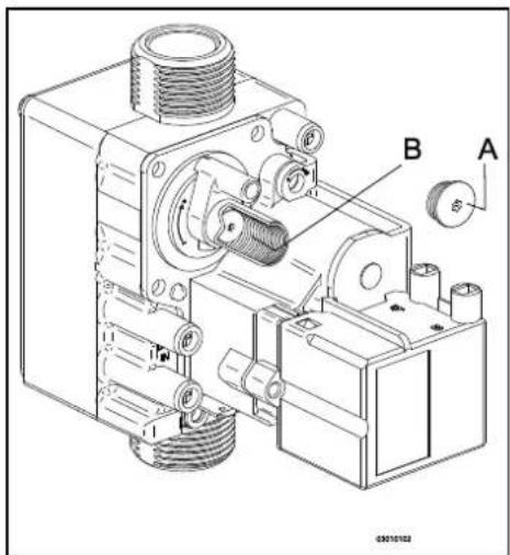
9.9 Checking the gas air ratio control
9.9.1 Checking flue gas at maximum power.
- Switch the appliance off with the Ⓐ button.
[-] will appear in service display.
- Remove the front panel by untightening the 2 screws.
- Remove the cap X of the flue gas sampling point on the adapter.
- Position the measuring probe or the flue gas analyser into the sampling point.
Important

- Ensure yourself that the analyser start up procedure has been finalized before placing the probe.
- The probe needs to close the sampling point fully to ensure an accurate measurement
-
The end (tip) of the probe must be completely in the flue gasses (in the middle of the flue pipe)
-
Switch the appliance on with the Ⓐbutton .
- Activate the test program for maximum output by simultaneously pressing the buttons
and twice. A capital H appears in service display.
Important
- Make sure a capital H is shown in the display to ensure the appliance to run at maximum power.

- Wait until the reading of the flue gas analyser is stable (minimal 3 minutes)
- Note the measured value O_2(H) or CO_2(H)
O2(H) = measured Q value at maximum power
CO_2(H) = Measured CO _2 value at maximum power
- Check if the measured value is in accordance with the data noted in table 2a or 2b.
Table 2a: Limits O₂(H) at maximum power (open casing)
| Limits | Gas category | |
| Natural gasG 20 | LPGG31 | |
| O_2 [%] | O_2 [%] | |
| Maximum value | 5.60 | 6.05 |
| Minimum value | 3.85 | 4.50 |
Table 2b: Limits CO₂(H) at maximum power (open casing)
| Limits | Gas category | |
| Natural gasG 20 | LPGG31 | |
| CO_2 [%] | CO_2 [%] | |
| Maximum value | 9.6 | 10.8 |
| Minimum value | 8.6 | 9.8 |

Important
- A deviation at maximum power can not be adjusted with the gas valve setting. When the value measured at maximum power is without the prescribed range the boiler has to be checked on gas tightness and usage of the correct components, in particular the gas ring, the insert and the fan.
- Proceed performing the measurement on minimum output (see § 9.9.2).

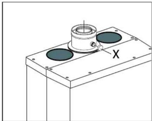
natural_image
Technical line drawing of a mechanical component with two circular holes and a central cylindrical feature, labeled 'X' (no text or symbols beyond the label)9.9.2 Checking flue gas at minimum power
Before measuring the flue gasses at minimum output the measurement of the maximum output must be completed. The measured O2 or CO2 value at maximum output is important for determining the correct value for the measurement at minimum output. See § 9.9.1 for measuring at maximum output
- Activate the test program for maximum output by simultaneously pressing the buttons and —. A capital L appears in service display.
- Wait until the reading of the analyser is stable (min. 3 minutes)
- Note the measured value O_2(L) or CO_2(L) . O_2(L) = is the measured value of O_2 at minimum power CO_2(L) = is the measured value of CO_2 at minimum power
- Check if the measured value is in accordance to the data in table 3a or 3b

The O2 lower limit is the value of O2(H) noted during the measurement at maximum output. The CO2 upper limit is the value of CO2(H) noted during the measurement at maximum output. (See § 9.9.1)
Table 3a: limits O₂(L) at minimum output (open casing)
| Limits | Gas category | |
| Natural gasG20 | LPGG31 | |
| O_2 [%] | O_2 [%] | |
| Maximum value | 6.00 | 6.65 |
| Minimum value | O_2 (H) | O_2(H) + 0.5 |
Table 3b: limits CO2(L) at minimum output (open casing)
| Limits | Gas category | |
| Natural gasG20 | LPGG31 | |
| CO_2 [%] | CO_2 [%] | |
| Maximum value | CO_2(H) | CO_2(H) - 0.3 |
| Minimum value | 8.4 | 9.4 |

Important
- The gas-air ratio is set correctly when the measured value at minimum output is within the upper and lower limit. Adjusting the gas-air ratio is not advised.
- The gas-air ratio needs to be adjusted in accordance to § 9.9.3 when the measured value at minimum output is not within the upper and lower limit.

For example (Natural gas G20)
During maximum output a O2(H) value of 4.0 % has been measured. In that case the O2(L) value at minimum output must be in-between 4 % (= value O2(H) and 6.05% as stated in the table. When during minimum output a value out of this range is measured the gas-air ratio must be adjusted..
- Proceed, in case of a deviating value by adjusting the gas valve in accordance to § 9.9.3. In case of a correct setting continue with point 6.
- Fit the front panel to the appliance and tighten the 2 screws. Check the values for CO at minimum output (= max. 160 ppm)
- Activate the test program for maximum output by simultaneously pressing the button and twice.
A capital H appears in service display.
Check the values for CO at maximum output (= max. 160 ppm)
Switch the appliance off with the button.
- Remove the measuring probe of the flue gas analyser and replace the cap on the sampling point.
- Check the tightness of the sampling point
- Switch the appliance off with the Ⓐ button and check that the appliance is functioning well.
9.9.3 Correction gas air ratio on minimum power
Before the correction of the gas air ratio on minimum output the measurement of the maximum output must be completed. The measured O2 or CO2 value at maximum output is important for determining the correct value for the measurement at minimum output. See § 9.9.1 and § 9.9.2 for measuring at maximum output.
-
Remove the cover cap (A) on the gas valve so setting screw B will become attainable.
-
Activate the test program for maximum output by simultaneously pressing the buttons ↗ and —. A capital L appears in service display.
- Wait until the reading of the analyser is stable (min. 3 minutes).
- Measure the O2(L) or CO2(L) value
- Set, using adjustment screw B de correct value for O2(L) or CO2(L).
See table 5a or 5b for the correct value

- Choose the correct table (4a and 5a is for natural gas, 4b and 5b is for Propane).
- The value measured at maximum output as noted during the measurement on maximum output (CO2(H) or O2(H)) Turning clockwise of the adjustment screw will raise the CO2 value and lower the O2 value. Turing anti clockwise will raise the O2 value and lower the CO2 value.
- Change the setting in small steps and wait until the reading is stable before continue.

Table 4a: Determining the correct setting of O_2 at minimum output for natural gas G20 (open casing)
| Natural gas G20 (20 mBar) | |
| Measured value am maxim power(See § 9.9.1 ) | Prescribed value at minimum power(= 0.5 x O_2(H) + 3.0) |
| O_2(H) [%] | O_2(L) [%] |
| 5.60 | 5.80 ±0.2 |
| 5.30 | 5.65 ±0.2 |
| 5.00 | 5.50 ±0.2 |
| 4.70 | 5.35 ±0.2 |
| 4.40 | 5.20 ±0.2 |
| 4.10 | 5.05 ±0.2 |
| 3.85 | 4.90 ±0.2 |
Table 4b: Determining the correct setting of O_2 at minimum output for propane G31 (open casing)
| Propane 3P G31 (30 & 50 mBar) | |
| Measured value am maxim power(See § 9.9.1 ) | Prescribed value at minimum power(= O_2(H) + 0.5 ) |
| O_2(H) [%] | O_2(L) [%] |
| 6.05 | 6.55 ±0.2 |
| 5.70 | 6.20 ±0.2 |
| 5.40 | 5.90 ±0.2 |
| 5.10 | 5.60 ±0.2 |
| 4.80 | 5.30 ±0.2 |
| 4.50 | 5.00 ±0.2 |
Table 5a: Determining the correct setting of CO_2 at minimum output for natural gas G20 (open casing)
| Natural gas G20 (20 mBar) | |
| Measured value am maxim power(See § 9.9.1 ) | Prescribed value at minimum power(= 0.5 x CO2(H) + 4.2) |
| CO2(H) [%] | CO2(L) [%] |
| 9.6 | 9.0 ±0.1 |
| 9.4 | 8.9 ±0.1 |
| 9.2 | 8.8 ±0.1 |
| 9.0 | 8.7 ±0.1 |
| 8.8 | 8.6 ±0.1 |
| 8.6 | 8.5 ±0.1 |
Table 5b: Determining the correct setting of CO_2 at minimum output for LPG G31 (open casing)
| LPG G31 (30 & 50 mBar) | |
| Measured value am maximim power(See § See § 9.9.1) | Prescribed value at minimum power(= CO2(H) - 0.3) |
| CO2(H) [%] | CO2(L) [%] |
| 10.8 | 10.5 ±0.1 |
| 10.6 | 10.3 ±0.1 |
| 10.4 | 10.1 ±0.1 |
| 10.2 | 9.9 ±0.1 |
| 10.0 | 9.7 ±0.1 |
| 9.8 | 9.5 ±0.1 |


Example (when using natural gas G20)
During the measurement at maximum output the value of O2(H) was 4.1 %.
The setting for O2(L) at minimum output will then be 5.05 ± 0.2 %
- Replace the cap A of the adjustment screw B for protection
- Repeat the measurement at maximum and minimum output (see § 9.9.1 and § 9.9.2) to ensure the correct operation of the boiler.

Important
Work on gas carrying parts may only be carried out by a qualified competent person.
Please refer to the Benchmark commissioning Checklist on page 60

10. FAULTS
10.1 Fault codes
When the service display or the operating panel is flashing, the burner controller has detected a fault. In case of several faults, the temperature display shows an additional code.
After the fault has been remedied, the burner controller can be restarted by pressing the reset button on the operating panel.
The following faults are detected and displayed:-
| Temperature display | Description | Possible cause/remedy |
| 10, 11, 12, 13, 14 | Sensor fault S1 | • Boiler needs venting (manual air vent top left of boiler)• Check the wires for breaks• Replace S1 |
| 20, 21. 22, 23, 24 | Sensor fault S2 | • Check the wires for breaks• Replace S2 |
| 0 | Sensor fault after self-check | • Check the wires for breaks• Replace boiler sensor S1 and/or S2 |
| 0.0 | Pressure sensor fault | • Repressurise central heating circuit via filling loop• Blocked pressure sensor |
| 1 | Temperature too high | • Air in system• Pump does not run• Too little circulation in system, radiators closed, pump setting too low• Isolation valve closed |
| 2 | Exchange S1 and S2 | • Check the cable loom• Replace S1 or S2 |
| 4 | No flame signal after 4 ignition attempts | • Gas isolation valve closed, or No gas at meter• Incorrect ignition distance• Faulty burner• Check earth fault• Gas inlet pressure too low, faulty governor at gas meter• Gas valve or ignition not powered• Boiler controller (PCB) |
| 5 | No flame signal after 4 restart attempts | • Condensate discharge blocked• Check setting of gas valve• Check earth |
| 6 | Flame detection fault | • Replace ignition cable + spark probe• Replace ignition unit• Burner control• Replace burner controller |
| 8 | Fan speed incorrect | • Fan rubs against casing• Wiring between fan and casing• Check the wires for poor contact (tacho signal)• Replace fan |
| 27 | Shortcut outside sensor | • Replace the outside sensor |
| 29, 30 | Relay gas valve defect | • Replace burner controller |

CAUTION
Always use original Intergas spare parts when replacing components.
Failure to fit the sensors S1 and/or S2, or to fit them correctly can result in serious damage.

CAUTION
* The boiler is equipped with a non-return valve (A), positioned above the fan. Ensure the non-return valve is repositioned correctly when replacing the fan.
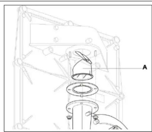
natural_image
Technical line drawing of a mechanical assembly with no visible text or symbols10.2 Other faults
10.2.1 Burner does not ignite
Possible causes:
Gas tap is closed.
No ↓
Air in the gas pipe.
No ↓
Gas supply pressure too low.
No ↓
No ignition.
No ↓
No spark. Ignition unit on gas valve faulty.
No ↓
Gas/air adjustment not correctly set.
No ↓
Fan faulty.
No ↓
Fan dirty.
No ↓
Gas valve faulty.
Solution:
→
Open gas tap.
→
Remove air form gas pipe.
→
Contact the gas supply company.
→
Replace ignition electrode.
→
Check the cabling. Check the spark plug cap. Replace the ignition unit.
→
Check adjustment. See gas/air adjustment.
→
Check the wiring. Check the fuse, if necessary, replace the fan.
→
Clean the fan.
→
Replace the gas valve. Re-adjust the gas valve, see gas/air adjustment
10.2.2 Burner ignites noisily
Possible causes:
Gas supply pressure too high.
No ↓
Incorrect ignition gap.
No ↓
Gas/air adjustment not correctly set.
No ↓
Weak spark.
Solution:
→
The house pressure switch may be faulty. Contact the gas company.
→
Replace the ignition pin.
Check the ignition electrode gap.
→
Check the setting. See gas/air adjustment.
→
Check the ignition gap.
Replace the ignition electrode.
Replace the ignition unit on the gas valve.
Checking ignition pin position using test tool

natural_image
Technical line drawing of a mechanical assembly with no visible text or symbolsPin must touch test tool
Pin must not touch test tool
Art. #: 899767.03
10.2.3 Burner resonating
Possible causes:
Gas supply pressure too low.
No ↓
Recirculation of combustion gasses.
No ↓
Gas/air adjustment not correctly set.
Solution:
The house pressure switch may be faulty. Contact the gas company.
→ Check the gas flue and the air supply.
→ Check the setting, see gas/air adjustment.
10.2.4 No heating (CH)
Possible causes:
Room thermostat / weather-dependent adjustment not closed or faulty.
No ↓
No current (24 V).
No ↓
Pump not running.
No ↓
Burner not firing on CH: sensor S1 or S2 faulty.
No ↓
Burner does not ignite.
Solution:
Check the wiring. Replace the thermostat. Replace the weather-dependant adjustment.
→ Check the wiring against the diagram. Check the connector X4. Replace the faulty manager.
→ Check the power supply. Check connector X2. Replace faulty pump.
→ Replace sensor S1 or S2. See fault code.
→ See burner does not ignite.
10.2.5 The power is reduced
Possible causes:
At high rpm the power has fallen by more than 5%.
Solution:
→ Check appliance and flue system for fouling. Clean the appliance and flue system.
10.2.6 CH does not reach temperature
Possible causes:
Room thermostat setting incorrect.
No ↓
Temperature is too low.
No ↓
Pump not running correctly. Pump setting is too low.
No ↓
No circulation in the installation.
No ↓
The boiler power has not been correctly set for the installation.
No ↓
No heat transfer as a result of lime scale or fouling in the heat exchanger.
Solution:
→ Check the setting and if necessary adjust.
→ Increase the CH temperature. See Operating CH. Check outside sensor for short-circuiting. Rectify.
→ Increase pump setting, or replace the pump.
→ Check whether there is circulation: at least 2 or 3 radiators must be open.
Adjust the power. See setting maximum CH power.
→ De-scale or flush the heat exchanger on the CH side.
10.2.7 No hot water (DHW)
Possible causes:
Flow sensor not functioning.
No ↓
No voltage at the flow sensor (5V DC).
No ↓
Burner not firing on DHW: S3 faulty.
No ↓
Burner does not ignite.
Solution:
→
Replace the flow sensor.
→
Check the wiring according to the diagram.
→
Replace S3.
→
See burner does not ignite.
10.2.8 Hot water does not reach temperature
Possible causes:
DHW flow to high.
No ↓
Temperature setting for water circuit too low.
No ↓
No heat transfer as a result of lime scale or fouling in the heat exchanger DHW side.
No ↓
Cold water temperature <10^ .
Solution:
→
Adjust the inlet assembly.
→
Set the hot water circuit, depending on the desired temperature.
→
Descale or flush the exchanger DHW side.
10.2.9 LED on CH pump is flashing alternately red and green.
Possible causes:
Mains voltage to high or to low.
No ↓
Temperature of the pump is to high
Solution:
→
Check the mains.
→
Check the water and environment temperature.
10.2.10 LED on CH pump is flashing red.
Possible causes:
Pump is not running
Solution:
Reset the pump by shutting of the boiler (stand-by or powerless) for at least 20 seconds.
Note: If the pump is set on "continuously active" (parameter 2 = 1) the boiler must be made powerless for at least 20 seconds.
11. MAINTENANCE
The appliance and the installation should be checked and if necessary cleaned every year by a registered expert.
For assembly and disassembly the following tools can be used:
- Cross head screwdriver
- Allen key 6 mm
- Fork spanner 30 mm
After servicing you must complete the Benchmark Service Record section located on page 60 of this document.

CAUTION
Work on gas carrying parts may only be carried out by an authorised installer.
When the appliance has just been operating parts may be hot. Domestic use only. Service intervals may need to be increased depending on commercial usage. This includes seals being replaced more frequently. For additional information please contact Intergas Heating Ltd.

CAUTION
The integrated insolation and burner seal contain ceramic fibres.
11.1 Disassembly
- Switch off the appliance using the On/Off key on the operating panel.
- Switch off the electrical supply to the appliance.
- Close the gas tap.
- Unscrew the two sunken screws left and right at the front underneath the appliance and lift/remove the front panel.
- Wait until the appliance and the burner have cooled down.
- Remove the connectors from the gas valve and the fan.
- Disconnect the coupling beneath the gas valve.
- Unscrew the 10 shoulder bolts from the front cover and remove this forwards complete with gas valve and fan.
While removing the front cover do not hold this at the gas valve and/or the fan. Be careful not to damage the burner and the fan while removing the front plate.
- The burner does not need any maintenance.
- Never clean the burner with a brush or compressed air. This causes damage to the metal fibre.
- Clean the bottom side of the heat exchanger and the condensate discharge at the bottom of the flue discharge behind the heat exchanger.
- The condensate must be thoroughly cleaned from the heat exchanger
- Remove the cup of the internal siphon at the bottom side of the boiler.

CAUTION
The amount of condensate water in the internal siphon exceeds the content of the cup. Please make sure a bucket is held under the cup when removing it.
- Clean the siphon cup and the condensate discharge pipe.
- After cleaning, fill the siphon with water by removing the hose that comes from the PRV. After filling the siphon make sure the hose is placed back
Note
A regular inspection of the build in expansion vessel pressure is advisable. Access to re-pressurise the expansion vessel is at the rear back of the vessel.

CAUTION
The boiler is equipped with a non-return valve (A), positioned above the fan. Check that the valve is still in good condition and ensure the valve is repositioned correctly when replacing the fan.
11.2 Assembly

CAUTION
When fitting the various seals check for damage, hardening, tears or hairline tears and/or discoloration. Where necessary fit a new seal. Also check whether seals are still correctly positioned.
Warranty will be void by not correctly replacing removed parts!
- Check if there is a small layer of ceramic grease on the contact surface between the shoulder bolt and the front plate. If necessary extra ceramic grease must be applied. See picture at the right.
- Make sure that the silicon gasket is well placed around the front cover.
- Mount the front cover to the heat exchanger and attach this with the shoulder bolts. Crosswise tighten the socket screws evenly by hand. The torque required for the front plate bolts is 10 - 12 Nm.
- Mount the gas coupling below the gas valve.
- Check the sealing ring for damage and replace if necessary.
- Fit the connectors on the gas valve and the fan.
- Open the gas tap and check the gas couplings below the gas valve and on the mounting bracket for leaks.
- Check the CH and the water pipes for leakage.
- Switch on the electrical supply to the appliance
- Put the appliance into operation.
- Check the front cover and the connection of the fan to the front cover for leaks.
- Check the combustion (see § 11.3)
- Fit the cover and screw it left and right at the bottom of the appliance.
- Check the heating system and the hot water supply.
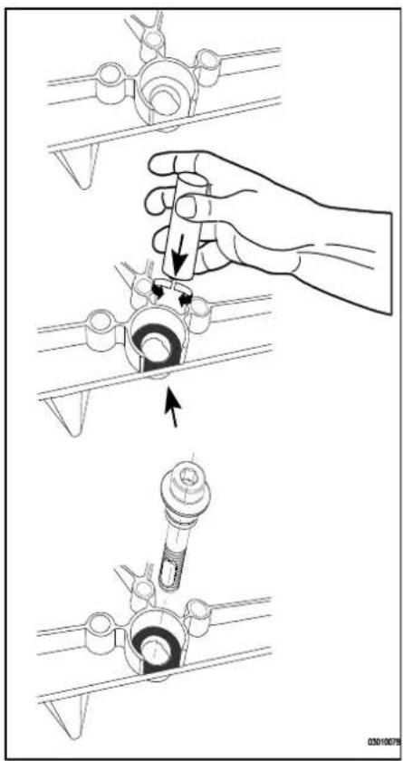
11.3 Combustion
During routine servicing, and after any maintenance or change of part of the combustion circuit the following must be checked:
- The integrity of the flue system and the flue seals, as described in § 8.5 and the British Standards codes of practices, specifically BS 5440.
- The integrity of the boiler combustion circuit and the relevant seals, as described in § 12.3.
The operational (working) gas inlet pressure at maximum rate, as described in § 10.7.
• The combustion performance, as described in § 10.7 and § 10.8.
BS 6798: 2009 Specification for installation and maintenance of gas-fired boilers of rated input not exceeding 70 kW net advises that:
- The person carrying out a combustion measurement should have been assessed as competent in the use of a flue gas analyser and the interpretation of the results;
- The flue gas analyser used should be one meeting the requirements of BS7927 or BS-EN50379-3 and be calibrated in accordance with the analyser manufacturers' requirements, and
- Competence can be demonstrated by satisfactory completion of the CPA1 ACS assessment, which covers the use of electronic portable combustion gas analysers in accordance with BS7967, Parts 1 to 4.
Connect the flue gas analyser to the flue gas sampling point (X) and check combustion as described in § 10.7. If the CO_2 percentage reading of the combustion gases at low setting falls into the bandwidth stated in § 10.8, the combustion setting is correct and no further adjustment is needed. If the combustion reading falls outside the prescribed tolerance band and the integrity of the complete flue system and combustion circuit seals have been verified as well as the inlet gas pressure proceed to adjust the gas/air ratio as described in § 10.8. When the CO_2 percentage at high setting is not within the prescribed tolerance band please contact Intergas Heating.
11.4 NTC resistances
| NTC 12 kOhm | |||||||||||
| T [°C] | R[ohm] | T [°C] | R[ohm] | T [°C] | R[ohm] | T [°C] | R[ohm] | ||||
| -15 | 76020 | 10 | 22800 | 35 | 8055 | 60 | 3253 | ||||
| -10 | 58880 | 15 | 18300 | 40 | 6653 | 65 | 2752 | ||||
| -5 | 45950 | 20 | 14770 | 45 | 5522 | 70 | 2337 | ||||
| 0 | 36130 | 25 | 12000 | 50 | 4609 | 75 | 1994 | ||||
| 5 | 28600 | 30 | 9805 | 55 | 3863 | 80 | 1707 | ||||
11.5 Electrical diagram
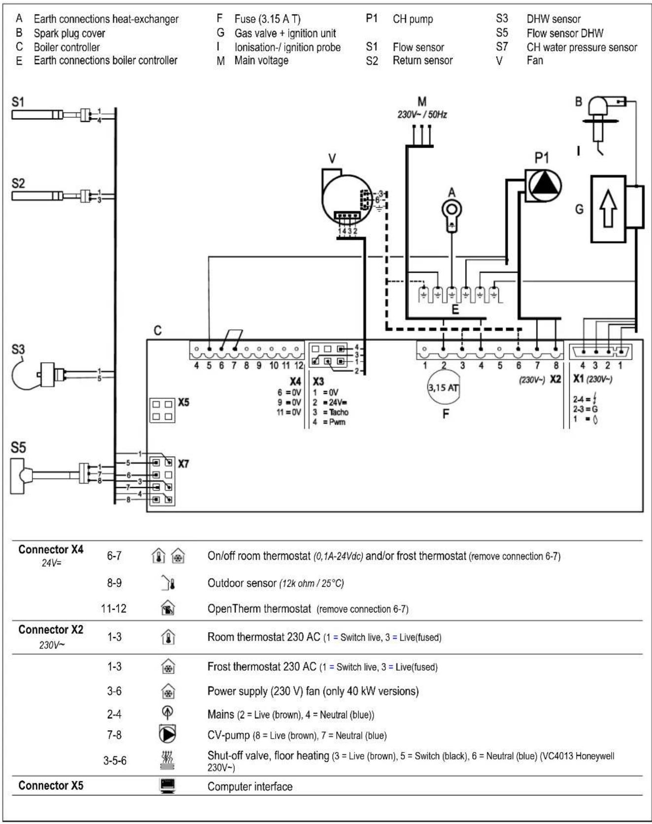
12. SHORT SPARES LIST
| Description | Article number |
| Boiler controller | 074857 |
| Fan 24 V | 074507 |
| Temperature sensor (heat exchanger) | 200117 |
| Temperature sensor (DHW) | 200177 |
| Modulating CH Pump | 210337 |
| Ignition / Ionisation electrode service set | 074337 |
| Ignition cable | 221467 |
| Gas valve Siemens Smart | 801597 |
| Ignition module Siemens TQG43 | 801537 |
| Condensate cup | 845597 |
| Flow sensor (DHW) | 844797 |
| Pressure gauge (CH) | 864137 |
| Seal gas valve (inlet) | 875757 |
| O-ring gas restriction ring | 875827 |
| O-ring front plate Rapid 25, 32 | 620274 |
| Seal ring condensate collector (heat exchanger connection) | 878147 |
| PRV | 844097 |
13. WARRANTY CONDITIONS
- The installer must be registered with Gas Safe, installer must complete the Benchmark Commissioning Checklist in full at the time the boiler is installed. The Benchmark must be made available and can be found at the back of the installation instructions. The Benchmark Commissioning Checklist must be retained on site by the owner/occupier for inspection during an engineers visit.
- The boiler warranty must be registered with Intergas by either the installer or you the householder, within 30 days of the boiler being installed. For the new build properties, this must be done within 30 days of the sale being completed. If these conditions are not met, the warranty will not be valid.
The product must be registered via the internet at www.intergasheating.co.uk or on the Intergas MiREG website www.myintergasregistration.co.uk or by returning the warranty card.
- The boiler must be serviced annually by a registered Gas Safe Engineer in accordance with manufacturer's instructions.
- Service details must be recorded in the Benchmark Checklist or provide proof of service which must be available for inspection.
- The cost of the annual service is not included in the warranty.
If the above conditions are not meet this warranty will be limited to 12 months from the date of installation or date of Manufacture, as recorded on the Benchmark commissioning checklist.

Important
Warranty terms mentioned above are based on domestic use only. Any non-domestic applications will be covered by a 12 months warranty. Service intervals may need to be increased depending on commercial usage. For additional information please contact Intergas Heating Ltd..
- Only boiler component failures are covered by the warranty. The warranty does not cover any connected system or accessories such as time switches, thermostats, motorised valves, external pumps and so on.
- Any repair carried out under the terms of this warranty does not extend the warranty beyond its original period.
- If the boiler breaks down, Intergas may ask you* (Homeowner or Installer) to pay a deposit before we visit to complete the repair. We will return the deposit in full if we find a fault that is covered by the warranty. We may keep the deposit if we cannot access the property at the time we have arranged with you to visit or we find other conditions of this warranty have not been met.
- The system must be flushed and cleansed in accordance with BS7593.
- If any failure is caused by contaminated water in the system the engineer visit becomes chargeable.
- All installation, non boiler or external system faults calls will be charged to the home owner/occupier.
- Roof space installation BS6798 2009 Require a permanently fixed access ladder must service installations in lofts or attics. Adequate lighting and permanently fixed flooring must also be available.
- Engineers will not carry out repairs if they think accessing the boiler would be a risk to Health and Safety. A responsible adult must be at the property to give our engineer access to the boiler.
-
If your boiler is in a cupboard, there must be enough room for the engineer to work (the minimum area as set out in the
-
In hard water areas of 200ppm or above, appropriate protection actions must be taken in accordance with BS 7593 in line with building regulations Part L1. (Above 200ppm we recommend Combimate*, Adey Electroscale or Hydroflow HS38 should be installed. 300ppm and above we recommend a Combimate* or Water softener* should be installed.) (*serviceable item)
- The central heating system must be maintained in accordance with the Benchmark Guidance on Water Treatment in Central Heating Systems & BS7593, we recommend the use of FERNOX, or ADEY inhibitors and Filters. It is important that correct concentration of water treatment is maintained for the life of the boiler, should we attend a warranty call we have the right to take a water sample. Should this fail the warranty will not be valid and will become chargeable. (BS 7593:2006)
- If the boiler suffers a breakdown you should contact Intergas on 01527 888000 selecting option 2. Our normal working hours, excluding Bank Holidays are: 8.00am – 5.00pm Monday to Friday and 8.00am – 12.00pm Saturday mornings.

Installers are required to carry out installation, commissioning and servicing work in accordance with the Benchmark Code of Practice which is available from the Heating and Hotwater Industry Council who manage and promote the scheme. Visit www.centralheating.co.uk for more information.
14 CE DECLARATION
Manufacturer Address
Intergas Heating Limited Unit 2 Easter Park Worcester Road Kidderminster DY11 7AR
Hereby declares that the CH appliances:
Rapid 25 Rapid 32
meets the provisions of the following directives:
• Low Voltage Directive (2014/35/EC)
• Gas Appliances Regulation (2016/426/EC)
- Boiler Efficiency Directive for new oil- and gas-fired central heating boilers (92/42/EC)
• EMC Directive (2014/30/EC)
• Ecodesign (2009/125/EG)
• Energy labelling 2010/30/EU

natural_image
Abstract line drawing with overlapping curved shapes (no text or symbols)Stephen Zouch, March 2019
15. GAS BOILER SYSTEM COMMISSIONING CHECKLIST
GAS BOILER SYSTEM COMMISSIONING CHECKLIST
This Commissioning Checklist is to be completed in full by the competent person who commissioned the boiler as a means of demonstrating compliance with the appropriate Building Regulations and then handed to the customer to keep for future reference.
Failure to install and commission according to the manufacturer's instructions and complete this Benchmark Commissioning Checklist will invalidate the warranty. This does not affect the customer's statutory rights.
| Customer name: | Telephone number: | ||||||||||||||||||||||
| Address: | |||||||||||||||||||||||
| Boiler make and model: | |||||||||||||||||||||||
| Boiler serial number: | |||||||||||||||||||||||
| Commissioned by (PRINT NAME): | Gas Safe register number: | ||||||||||||||||||||||
| Company name: | Telephone number: | ||||||||||||||||||||||
| Company address: | |||||||||||||||||||||||
| Commissioning date: | |||||||||||||||||||||||
| To be completed by the customer on receipt of a Building Regulations Compliance Certificate*Building Regulations Notification Number (if applicable): | |||||||||||||||||||||||
| CONTROLS (tick the appropriate boxes) | |||||||||||||||||||||||
| Time and temperature control to heating Room thermostat and programmer/timerLoad/weather compensation | Programmable room thermostat | ||||||||||||||||||||||
| Optimum start control | |||||||||||||||||||||||
| Time and temperature control to hot water Cylinder thermostat and programmer/timer | Combination Boiler | ||||||||||||||||||||||
| Heating zone valves Fitted | Not required | ||||||||||||||||||||||
| Hot water zone valves Fitted | Not required | ||||||||||||||||||||||
| Thermostatic radiator valves Fitted | Not required | ||||||||||||||||||||||
| Automatic bypass to system Fitted | Not required | ||||||||||||||||||||||
| Boiler interlock Provided | |||||||||||||||||||||||
| ALL SYSTEMS | |||||||||||||||||||||||
| The system has been flushed and cleaned in accordance with BS7593 and boiler manufacturer's instructions Yes | |||||||||||||||||||||||
| What system cleaner was used? | |||||||||||||||||||||||
| What inhibitor was used? Quantity litresHas a primary water system filter been installed? Yes No | |||||||||||||||||||||||
| CENTRAL HEATING MODE measure and record: | |||||||||||||||||||||||
| Gas rate | m3/hr | OR | ft3/hr | ||||||||||||||||||||
| Burner operating pressure (if applicable) | mbar | OR Gas inlet pressure | mbar | ||||||||||||||||||||
| Central heating flow temperature °C | |||||||||||||||||||||||
| Central heating return temperature °C | |||||||||||||||||||||||
| COMBINATION BOILERS ONLY | |||||||||||||||||||||||
| Is the installation in a hard water area (above 200ppm)? Yes NoIf yes, has a water scale reducer been fitted? Yes No | No | ||||||||||||||||||||||
| What type of scale reducer has been fitted? | No | ||||||||||||||||||||||
| DOMESTIC HOT WATER MODE Measure and Record: | |||||||||||||||||||||||
| Gas rate | m3/hr | OR | ft3/hr | ||||||||||||||||||||
| Burner operating pressure (at maximum rate) mbar OR Gas inlet pressure at maximum rate mbarCold water inlet temperature °CHot water has been checked at all outlets Yes Temperature °CWater flow rate l/min | mbar OR Gas inlet pressure at maximum rate mbarYes Temperature °CWater flow rate l/min | ||||||||||||||||||||||
| CONDENSING BOILERS ONLY | |||||||||||||||||||||||
| The condensate drain has been installed in accordance with the manufacturer's instructions and/or BS5546/BS6798 Yes | |||||||||||||||||||||||
| ALL INSTALLATIONS | |||||||||||||||||||||||
| Record the following: | At max. rate: CO ppm AND CO/CO2 RatioAt min. rate: (where possible) CO ppm AND CO/CO2 RatioMandatory Requirement CO2 @Max Rate % CO2 @Min Rate %The heating and hot water system complies with the appropriate Building Regulations YesThe boiler and associated products have been installed and commissioned in accordance with the manufacturer's instructions YesThe operation of the boiler and system controls have been demonstrated to and understood by the customer YesThe manufacturer's literature, including Benchmark Checklist and Service Record, has been explained and left with the customer YesCommissioning Engineer's SignatureCustomer's Signature(To confirm satisfactory demonstration and receipt of manufacturer's literature) | ||||||||||||||||||||||
All installations in England and Wales must be notified to Local Authority Building Control (LABC) either directly or through a Competent Persons Scheme. A Building Regulations Compliance Certificate will then be issued to the customer.
© Heating and Hotwater Industry Council (HHIC)

www.centralheating.co.uk
16. SERVICE RECORD
SERVICE INTERVAL RECORD
It is necessary that your heating system is serviced annually to validate your warranty and that the appropriate Service Interval Record is completed.
Service Provider
Before completing the appropriate Service Record below, please ensure you have carried out the service as described in the manufacturer's
instructions. Always use the manufacturer's specified spares when replacing parts.
| SERVICE 01 | Date: | ||||
| Engineer name: | |||||
| Company name: | |||||
| Telephone No: | |||||
| Gas safe register No: | |||||
| Record: | Al max. rate: CO ppm | AND | CO2% | ||
| At min. rate: CO ppm | AND | CO2% | |||
| CO/CO2Ratio min. rate max rate | |||||
| Comments: | |||||
| Signature | |||||
| SERVICE 03 | Date: | |||||
| Engineer name: | ||||||
| Company name: | ||||||
| Telephone No: | ||||||
| Gas safe register No: | ||||||
| Record: | At max. rate: | CO ppm | AND | CO2% | ||
| At min. rate: | CO ppm | AND | CO2% | |||
| CO/CO2 Ratio min. rate max rate | ||||||
| Comments: | ||||||
| Signature | ||||||
| SERVICE 05 | Date: | |||||
| Engineer name: | ||||||
| Company name: | ||||||
| Telephone No: | ||||||
| Gas safe register No: | ||||||
| Record: | Al max. rate: | CO ppm | AND | CO2% | ||
| Al min. rate: | CO ppm | AND | CO2% | |||
| CO/CO2 Ratio min. rate max rate | ||||||
| Comments: | ||||||
| Signature | ||||||
| SERVICE 07 | Date: | |||||
| Engineer name: | ||||||
| Company name: | ||||||
| Telephone No: | ||||||
| Gas safe register No: | ||||||
| Record: | At max. rate: | CO ppm | AND | CO2% | ||
| At min. rate: | CO ppm | AND | CO2% | |||
| CO/CO2Ratio | min. rate | max rate | ||||
| Comments: | ||||||
| Signature | ||||||
| SERVICE 09 | Date: | |||||
| Engineer name: | ||||||
| Company name: | ||||||
| Telephone No: | ||||||
| Gas safe regisler No: | ||||||
| Record: | At max. rate: | CO ppm | AND | CO2% | ||
| At min. rate: | CO ppm | AND | CO2% | |||
| CO/CO2 Ratio min. rate max rate | ||||||
| Comments: | ||||||
| Signature | ||||||
| SERVICE 02 | Date: | ||||
| Engineer name: | |||||
| Company name: | |||||
| Telephone No: | |||||
| Gas safe register No: | |||||
| Record: | At max. rate: CO ppm | AND | CO2% | ||
| At min. rate: CO ppm | AND | CO2% | |||
| CO/CO2 Ratio min. rate max rate | |||||
| Comments: | |||||
| Signature | |||||
| SERVICE 04 | Date: | ||||
| Engineer name: | |||||
| Company name: | |||||
| Telephone No: | |||||
| Gas safe register No: | |||||
| Record: | At max. rate: | CO | ppm | AND | CO2% |
| At min. rate: | CO | ppm | AND | CO2% | |
| CO/CO2Ratio min. rate | max rate | ||||
| Comments: | |||||
| Signature | |||||
| SERVICE 06 | Date: | |||||
| Engineer name: | ||||||
| Company name: | ||||||
| Telephone No: | ||||||
| Gas safe register No: | ||||||
| Record: | At max. rate: | CO ppm | AND | CO2% | ||
| At min. rate: | CO ppm | AND | CO2% | |||
| CO/CO2 Ratio min. rate max rate | ||||||
| Comments: | ||||||
| Signature | ||||||
| SERVICE 08 | Date: | ||||
| Engineer name: | |||||
| Company name: | |||||
| Telephone No: | |||||
| Gas safe register No: | |||||
| Record: | At max. rate: | CO ppm | AND | CO2% | |
| At min. rate: | CO ppm | AND | CO2% | ||
| CO/CO2Ratio min. rate | max rate | ||||
| Comments: | |||||
| Signature | |||||
| SERVICE 10 | Date: | |||
| Engineer name: | ||||
| Company name: | ||||
| Telephone No: | ||||
| Gas safe register No: | ||||
| Record: | At max. rate: CO ppm | AND | CO2% | |
| At min. rate: CO ppm | AND | CO2% | ||
| CO/CO2Ratio min. rate | max rate | |||
| Comments: | ||||
| Signature | ||||
*All installations in England and Wales must be notified to Local Authority Building Control (LABC) either directly or through a Competent Persons Scheme. A Building Regulations Compliance Certificate will then be issued to the customer.
© Heating and Hotwater Industry Council (HHIC)

www.centralheating.co.uk
Intergas Heating Ltd
Intergas Heating Limited
Unit 2, Easter Park
Worcester Road
Kidderminster
DY11 7AR
Telephone
: 01527 888000
Fax : 01384 279480
info@intergasheating.co.uk
www.intergasheating.co.uk

88923806

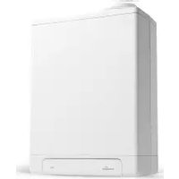
- Rapid 25
- Rapid 32
- Installation Manual
- CONTENTS
- PREFACE 5
- SAFETY REGULATIONS 8
- TECHNICAL SPECIFICATIONS 10
- MAIN COMPONENTS 12
- INSTALLER IMPORTANT POINTS 18
- INSTALLATION 20
- CONNECTIONS 24
- COMMISSIONING 40
- SETTING AND ADJUSTMENT 45
- FAULTS 55
- MAINTENANCE 60
- SHORT SPARES LIST 64
- WARRANTY CONDITIONS 65
- CE DECLARATION 65
- GAS BOILER SYSTEM COMMISSIONING CHECKLIST 66
- SERVICE RECORD 67
- PREFACE
- Regulation
- Warnings
- Manual handling
- Warnings on the box
- Pictograms
- CAUTION
- WARNING HIGH VOLTAGE
- This manual
- Icons
- Service and technical support
- Product identification
- SAFETY REGULATIONS
- General
- Safety precautions If you smell gas
- The Installation
- Reference should also be made to:
- Approvals
- TECHNICAL SPECIFICATIONS
- Technical data
- Product Fiche according to CELEX-32013R0811, ANNEX IV
- MAIN COMPONENTS
- General Boiler Information
- Note
- Boiler controller
- Parameter list
- Heat transfer
- Central heating system
- Room temperature control
- Integrated clock
- Operation
- Operating modes
- Ventilation
- Ignition
- CH operation
- DHW operation
- Pre heating exchanger
- Clock function
- PC Interface
- Test programs
- Additional readings :
- Frost protection
- INSTALLER IMPORTANT POINTS
- Please read all instructions before fitting this appliance
- Accessories
- Flues
- INSTALLATION
- Overall dimensions
- Boiler location
- Installation in a kitchen cupboard
- Installation in an airing cupboard
- Remove front panel
- Assembly
- Fitting the mounting strip
- Fitting the spacer frame
- Mount the appliance
- CONNECTIONS
- Connect the CH system
- The CH system should be provided with:-
- Expansion vessel
- Thermostatic radiator valves
- Underfloor heating
- Weather compensation and heating DHW cylinder on hot water priority or W system
- Electrical diagram indirectly heated DHW storage cylinder
- Appliance with zone control.
- Schedule zone-regulation
- Operating principle
- Installation
- Domestic hot water system
- Notes
- Flow Resistance graph for appliance DHW circuit
- Appliance with solar water heater post-heating
- Connection diagram for solar heater post -heating
- Electrical connection
- On / Off room thermostat
- Open Therm room thermostat
- Outside temperature sensor
- 230 volt room thermostat
- S and Y zone plans
- Condensate disposal
- Gas connection
- Flue system
- General
- Sealed flue system.
- Concentric connection.
- Flue pipe and air supply
- Length flue pipe and air inlet when connecting to a concentric flue system
- Horizontal flue system
- Vertical flue system
- Plume management kit
- Flues in voids
- Free in the market available flue systems (C63)
- IMPORTANT
- Securing the flue system
- COMMISSIONING
- Fill and de-aerate the appliance and the system
- WARNING
- CH system
- Hot water supply
- Gas supply
- Combustion
- Flue system
- Commissioning of the appliance
- Read-out
- Operation
- Setting and adjusting the clock functions
- Setting the clock
- Setting the timer function
- Additional functions
- Shutting down
- Frost protection
- System Shutdown
- Frost protection
- Note!
- SETTING AND ADJUSTMENT
- Directly via the operating panel
- Appliance on/off
- DHW comfort
- Resetting
- Changing the settings of the various functions:
- Maximum CH supply temperature
- Settings through the service code
- Parameters
- Enable/disable keep hot facility by Open Therm room thermostat.
- Setting maximum CH power
- Setting pump position
- Weather-dependent control
- Conversion to different gas type
- Converting the gas restriction.
- Gas-Air ratio control.
- Checking the gas air ratio control
- Checking flue gas at maximum power.
- Checking flue gas at minimum power
- For example (Natural gas G20)
- Correction gas air ratio on minimum power
- Example (when using natural gas G20)
- FAULTS
- Fault codes
- Other faults
- Burner does not ignite
- Burner ignites noisily
- Burner resonating
- No heating (CH)
- The power is reduced
- CH does not reach temperature
- No hot water (DHW)
- Hot water does not reach temperature
- LED on CH pump is flashing alternately red and green.
- LED on CH pump is flashing red.
- MAINTENANCE
- Disassembly
- Assembly
- Combustion
- Electrical diagram
- SHORT SPARES LIST
- WARRANTY CONDITIONS
- CE DECLARATION
- GAS BOILER SYSTEM COMMISSIONING CHECKLIST
- GAS BOILER SYSTEM COMMISSIONING CHECKLIST
- SERVICE RECORD
- SERVICE INTERVAL RECORD
- Intergas Heating Ltd
Brand : Intergas
Model : Rapid 32 Plus
Category : Heat pump