
Superflow 45 - Boiler Intergas - Free user manual and instructions
Find the device manual for free Superflow 45 Intergas in PDF.


| Product Type | Boiler |
| Brand | Intergas |
| Model | Superflow 45 |
| Energy Source | Gas (natural or LPG) |
| Heat Output (kW) | 45 kW |
| Efficiency | Up to 94% (condensing) |
| Water Capacity (liters) | 10 liters (expansion vessel) |
| Dimensions (H x W x D) | 700 x 400 x 300 mm |
| Weight | 35 kg |
| Flue Type | Room sealed (concentric) |
| Ignition | Electronic |
| Main Functions | Central heating and domestic hot water (if combi), or heating only |
| Control Panel | Digital display with push buttons |
| Safety Features | Overheat protection, flame failure, frost protection, low water pressure cut-off |
| Compatibility | Compatible with most thermostat brands (OpenTherm) |
| Maintenance | Annual service recommended by qualified engineer |
| Cleaning | External surfaces wipe with damp cloth; no abrasive cleaners |
| Spare Parts Availability | Genuine Intergas parts available through authorized dealers |
| Repairability Index | High (modular design, easy access to key components) |
| Noise Level (dB) | ~50 dB (at 1m) |
| Certification | CE, UKCA |
Frequently Asked Questions - Superflow 45 Intergas
User questions about Superflow 45 Intergas
0 question about this device. Answer the ones you know or ask your own.
Ask a new question about this device
Download the instructions for your Boiler in PDF format for free! Find your manual Superflow 45 - Intergas and take your electronic device back in hand. On this page are published all the documents necessary for the use of your device. Superflow 45 by Intergas.
USER MANUAL Superflow 45 Intergas
INSTALLATION MANUAL
HIGH EFFICIENCY GAS FIRED INSTANTANEOUS WATER HEATER
Read this installation manual thoroughly before the installation and use of the water heater. Follow all indicated instructions. This installation manual must remain with the water heater.
Benchmark places responsibilities on both manufacturers and installers. The purpose is to ensure that customers are provided with the correct equipment for their needs, that it is installed, commissioned and serviced in accordance with the manufacturer's instructions by competent persons and that it meets the requirements of the appropriate Building Regulations. The Benchmark Checklist can be used to demonstrate compliance with Building Regulations and should be provided to the customer for future reference. Please read the Benchmark Checklist carefully, page 87, and complete all sections, as required by law, relevant to the appliance and installation. Failure to install and commission according to the manufacturer's instructions and complete the Benchmark Commissioning Checklist will invalidate the warranty for the Gas Appliance installation. The details within the Checklist will be required in the event of any warranty work. On completion the Checklist must be left with the end user. The relevant sections of the Service Record, page 88, 89 & 90, must be completed on each subsequent Service visit.
Installers are required to carry out installation, commissioning and servicing work in accordance with the Benchmark Code of Practice which is available from the Heating and Hotwater Industry Council who manage and promote the scheme. Visit www.centralheating.co.uk for more information.
CONTENTS
| 1 | Preface | 4 |
| 1.1 | Regulation | 4 |
| 1.2 | Warnings | 4 |
| 1.3 | Manual handling | 4 |
| 1.4 | Pictograms | 5 |
| 1.5 | Warnings on the box | 5 |
| 1.6 | Abbreviations | 5 |
2 Safety regulations 6
2.1 General 6
2.2 The installation 6
3 General appliance information 7
3.1 General....7
3.1.1 UKCA label....7
3.1.2 Gas category....7
3.2 Operation 8
3.3 Data plate 8
3.4 Control panel 9
3.5 Operational modes....9
4 Main components 10
4.1 Standard scope of delivery....11
4.2 Accessories....12
5 Installation 14
5.1 Overall dimensions....14
5.2 Installation location....15
5.2.2 Removing/installing the front panel 16
5.3 Installing the appliance....17
6 Connection 18
6.1 Domestic hot water connection....18
6.1.1 Domestic hot water circuit resistance graph....18
6.2 Electrical connection....19
6.3 Gas connection 19
6.4 Cascade function....20
6.5 Flue and air supply duct 23
6.5.1 Draft, materials and insulation 23
6.6 Pipeline lengths....24
6.6.1 Replacement lengths....24
6.6.2 Example calculation....24
6.7 General layout of the flue 25
6.7.1 Wall terminal with twin-pipe horizontal terminal C13 26
6.7.2 Flue terminal positions 60/100mm 27
6.7.3 PMK terminal positions 60mm 28
6.7.4 Roof terminal with combi-pipe vertical terminal C33....29
6.7.5 Roof terminal and air supply duct from the façade C53 30
6.7.6 Clamping the flue system (twin and concentric) 31
6.7.7 Twin flue terminal positions 33
7 Operation 34
7.1 Using the control panel....34
7.2 Appliance preparation....34
7.2.1 Domestic hot water facility....34
7.2.3 Gas supply 34
7.3 Commissioning procedure....35
7.4 Shutting down the appliance 35
8 Settings and adjustments 36
8.1 Navigate the settings 36
8.1.1 Main menu 36
8.1.2 Domestic hot water menu 37
8.1.3 Service menu 38
8.1.4 Parameters 39
8.1.5 Info menu 40
8.1.6 Cascade menu 41
8.2 Conversion to another gas type 42
8.3 Gas/air control 43
8.4 Inspection of gas air control....44
8.4.1 Measuring flue gas at high fire....44
8.4.2 Measuring flue gas at low fire....45
8.4.3 Minimum output correction....47
9 Faults 48
9.1 Fault codes 48
9.2 Other faults....50
9.2.1 No domestic hot water (DHW) 50
9.2.2 Domestic hot water does not reach the correct temperature....50
9.2.3 Burner ignites loudly 50
9.2.4 Burner resonates....51
9.3 Notifications....51
9.4 Deviating from household use 52
10 Maintenance 53
10.1 Annual service A....54
10.1.1 Appliance check-up 54
10.1.2 Preparations....54
10.1.3 Cleaning....54
10.1.4 Syphon maintenance....55
10.1.5 Service B 57
10.1.6 Service C 57
10.1.7 Assembly 58
10.1.8 Commissioning and end control 58
11 Technical specifications 60
11.1 Electrical schematic....61
11.2 Product card according to CELEX-32013R0811, Appendix IV 63
11.3 NTC resistances....63
12 Guarantee provisions and CE declaration 64
1 PREFACE
The manufacturer Intergas Heating Ltd accepts no liability whatsoever for damage or injury caused by failure to adhere (strictly) to the safety regulations and instructions, or carelessness during installation of the Intergas wall mounted gas fired boiler and any associated accessories
Intergas Heating Ltd are continuously developing ways to guarantee the quality of its products and to improve them where necessary. In so doing we (Intergas Heating Ltd.) reserve the right to modify at any time the features named within this document.
Read and observe all safety instructions within this instruction manual to prevent unsafe situations, fire, explosion, damage to property or personal injury.
1.1 Regulation
The Intergas appliance meets the requirements of Statutory Instrument 'The Appliance (Efficiency) Regulations' and is deemed to meet the requirements of:
▶ Low Voltage Directive (2014/35/EU)
Gas Appliances Regulation (EU) 2016/426
▶ Appliance Efficiency Directive (92/42/EEC)
▶ EMC Directive (2014/30/EU)
▶ RED Directive (2014/53/EU)
▶ Ecodesign (2009/125/EC)
▶ Energy labelling Regulation (EU) 2017/1369
1.2 Warnings
Intergas accepts no responsibility for the unsatisfactory performance of the appliance or flue arising from the failure to comply with this installation manual. Incorrect installation could invalidate your guarantee and may lead to prosecution.
The appliance cannot be removed from the original place of installation and transferred to another site or re-sold without prior consent from Intergas. You must re-register the appliance with Intergas in order to maintain any remaining warranty.
The boiler must be installed by a competent Gas Safe registered engineer and in accordance with these instructions, It is the installers responsibility to ensure that the installation conforms to the current legislation and Standard Codes of Practice.
Please read these instructions carefully before installing or using the appliance.
1.3 Manual handling
When moving the boiler always keep your back straight, bend your knees, don't twist, move your feet. Avoid bending forwards or sideways and keep the load as close to your body as possible. Where possible transport the boiler using a suitable trolley, sack truck or get some assistance. Grip the boiler firmly and before lifting establish where the weight is concentrated to determine the centre of gravity, repositioning yourself if necessary.
1.4 Pictograms
The following pictograms are used in this installation manual:

CAREFUL / IMPORTANT
Procedures which, if these are not performed with the required caution, can damage the product, the surrounding or the environment or may result in personal injury.

COMMENT
Procedures and/or instructions which, if they are not followed, can negatively affect the operation of the appliance.

SEE
Reference to other manuals
1.5 Warnings on the box

INSTRUCTION (THIS SIDE UP)
Store the appliance upright as indicated on the box.

INSTRUCTION (FRAGILE)
This is a fragile piece of equipment: Please be very careful not to drop.

INSTRUCTION (FRAGILE)
This is a fragile piece of equipment: Please provide a dry storage for the appliance.

INSTRUCTIE (STACK)
No more than three boxes should be stacked on top of each other.
1.6 Abbreviations
▶ DHW: Domestic hot water
▶ CW: Comfort domestic hot water
▶ HE: High efficiency
▶ PHS: Pre Heated Solar water.
▶ PC: Personal computer

Sensor (Negative temperature coefficient)
▶ PP: Polypropylene
▶ CCS: Concentric Chimney System
( Combination air supply duct and combustible gas flue system)
Safety precautions If you smell gas

A gas leak could potentially cause an explosion. If you smell gas, observe the following rules:
▶ Prevent flames or sparks:
- Do not smoke, use a lighter or strike matches.
- Do not operate any electrical switches or unplug any equipment.
- Do not use the telephone or ring doorbells.
▶ Turn off the gas at the meter or regulator.
▶ Open windows and doors.
▶ Warn your neighbours and leave the building
▶ Prevent anyone from entering the building.
▶ Call the National Gas Emergency Service on 0800 111 999.
L.P.G. appliances: Call the supplier's number on the side of the gas tank

HEATING & HOTWATER INDUSTRY COUNCIL
2.1 General
Depending on the year of construction, an Intergas HR appliance may contain part(s) in which ceramic fibers are used. Always use the recommended personal protective equipment when working with ceramic fibers.
It is law that all gas appliances are installed and serviced by a Gas Safe registered competent engineer, if in any doubt please check with Gas Safe (0800 408 5500) and in accordance with the following recommendations:
▶ Current Gas Safety (Installation and Use) Regulations
▶ All current building regulations
▶ Building Standards (Scotland) Consolidated
I.S.813 Installation of Gas Appliances (Ireland)
▶ IET Wiring Regulations (BS 7671)
▶ Health and Safety Document (Electricity at Work Regulations)
UK Water fittings Regulations and Byelaws
▶ Health & Safety Regulations
2.2 The installation
The installation must comply with the following British Standards codes of practice:
BS 5440: Flueing and Ventilation for gas appliances of rated input not exceeding 70kW (Part 1 Flues)
BS 5440: Flueing and Ventilation for gas appliances of rated input not exceeding 70kW (Part 2 Air Supply)
BS 5546: 2010 Specification for installation and maintenance of gas-fired water-heating appliances of a rated input not exceeding 70Kw net.
BS EN 12828:2012+A1:2014 Heating systems in buildings. Design for water-based heating systems
BS EN 806-1:2000 Specifications for installations inside buildings conveying water for human consumption. General (802-2 Design, 806-3 Pipe sizing, 806-4 Installation, 806-5 Operation and maintenance).
BS 6798: 2014 Specification for selection, installation, inspection, commissioning, servicing and maintenance of gas-fired boilers of rated input not exceeding 70kW net
BS 6891: 2015+A1:2019 Specification for the Installation and maintenance of low pressure gas installation pipework of up to 35mm (R1 1/4) on premises
BS 7593: 2019 Code of practice for the preparation, commissioning and maintenance of domestic central heating and cooling water in systems
BS 7671: 2018 Requirements for electrical installations, IET Wiring regulations
BS 5955-8:2001 Plastic pipework (thermoplastics materials). Specification for the installation of thermoplastic pipes and associated fittings for use in domestic hot and cold services and heating systems in buildings.
Reference should also be made to:
▶ Guide to condensing boiler installation assessment procedures for dwellings (SBSA)
The institute of Gas Engineers document & managers IGE/UP/7 Gas installations in timber frame and light steel framed buildings.
3.1 General
The Intergas Superflow is a Tankless Water Heater. The appliance is solely intended for supplying heat for the water in a domestic hot water installation for household use.
The appliance serves to provide hot water to one or more tap points, for example washbasins, showers and bathtubs.
Household use means that the appliance consumes a maximum of 2000 m 3 of natural gas per year. When the appliance is used in a non-household application, the warranty provisions and maintenance instructions stated in this document no longer apply. Please contact Intergas Heating Ltd. for appropriate advice.
The Intergas Superflow meets the directives and additional national regulations of the United Kingdom that are indicated by UKCA marking. The associated conformity declaration can be requested from Intergas Heating Ltd (also see §12).
The Intergas Superflow meets the electrical protection class IPX4D.
Note: The appliance is equipped with software that measures the intensity of use. If the gas consumption deviates strongly from the use suitable for domestic use, after the maximum gas quantity has been exceeded, a notification (n120 - n121 - n122) will appear on the display, the output will be reduced and eventually the heat demand will be blocked.
After carrying out maintenance, this message can be reset by the installer. Also see §9.4.
3.1.1 UKCA label
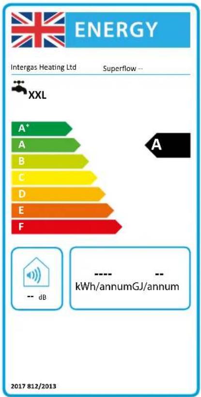
Based on the UKCA marking all newly produced gas fired appliances have to meet minimum standards regarding energy performance. The Intergas Superflow carries an UKCA energy label containing specific information regarding energy efficiency class, noise level and maximum power.
The Intergas Superflow carries label A for domestic hot water. In addition, the Intergas Superflow meets XXL capacity profile for domestic hot water.
The extensive product fiche can be found in §11.2.
3.1.2 Gas category
| Gas category Gas type Gas inlet pressure (mbar) | |
| II2H3P | Natural gas (G20) 20 |
| LPG (G31) 37 | |
The Intergas Superflow 45 and 60 are factory set for H-gas, G20. The appliance may optionally be converted to another gas type using a conversion set (see §8.2).

3.2 Operation
The Intergas Superflow is a modulating high efficiency domestic hot water heater. This means that the appliance has an electronically controlled power adjustment which ensures that the amount of gas is adjusted continuously, depending on the amount of water used. This ensures that a constant temperature of the domestic hot water is realized, regardless of the domestic hot water flow.
The Intergas Superflow works according to the flow principle. The domestic hot water is only heated when there is a heat demand, and a copper circuit is integrated in the aluminium heat exchanger for this purpose.
The appliance has a Appliance Memory Module (BMM). All appliance-specific settings, including serial number, time meter, and faults, are or will be stored in this module. The module must remain in the appliance at all times; it ensures that the burner controller operates correctly.

CAREFUL
Placing the BMM in a appliance other than that in which it is delivered can lead to dangerous situations.

3.3 Data plate
Identification of the product
You will find the unit details on the data plate on the bottom of the appliance. The data plate contains, important information and the appliance specification (appliance type and model name), and the serial number:
| ****-yymm**** | Production code - Serial numberYY = year of production,mm = month of production | |
| PIN | Product Information Number | |
 | Data related to Domestic Hot Water | |
| Information regarding electrical power supply(Voltage, mains frequency, elmax, IP-class) | ||
| P | Permissible overpressure in DHW circuit in bar | |
| Qn HS | Input related to gross caloric value in kilowatts | |
| Qn Hi | Input related to net caloric value in kilowatts | |
| Pn | Output in kilowatts | |
| GB | Countries of Destination (EN 437) | |
| II2H3P | Approved unit categories (EN 437) | |
| G20-20 mbarG31-37 mbar | Gas group and gas connection pressure as setat the factory (EN 437) | |
| B23,......C93(x) | Approved flue gas category (EN 15502) | |
| NOx class | Emission class 6 | |
| Tmax | Maximum flow temperature in °C | |
| IPX4D | Electrical protection class | |
3.4 Control panel
The appliance has a fully integrated touch screen control panel that also displays information about the operational status, temperature settings, demand symbols and fault codes.
The display has multiple functions and options please refer to section §8 for further detail.

COMMENT
The touch screen is very sensitive only use a finger tip and not any sharp objects.

3.5 Operational modes
The appliance has a number of operational modes:
The appliance is switched off.
The appliance is switched off but is connected to the mains voltage. In this mode, the display view is characterised by:
▶ Showing the power LED [].
▶ Showing a line on the right display:

Appliance is switched off (mains voltage is present, however)
The appliance is switched on.
The appliance is switched on and is ready to respond to a request for domestic hot water. In this mode, the display view is characterised by:
▶ Showing the power LED []. All other symbols and values are not displayed.

Appliance is switched on
The appliance is in operation.
The appliance is in operation and is supplying domestic hot water to one or more tap points. The display view is characterised by:

Appliance is in operation
▶ Showing the power LED [].
▶ Showing the flame. The burner is switched on [].

4.1 Standard scope of delivery

Check whether the package is undamaged. Unpack the boiler and check whether all components are present. Also check for any damages to the boiler or accessories and, if present, immediately notify the supplier.
 |  |  |
| Appliance Wall bracket Flexible hose | ||
 |  |  |
| Installation and operation instruction | Guarantee card | Connection set, consists of:Cold water inlet isolation valve(1x)Threaded adapter hot water outlet (1x)Gas isolation valve (1x)Gasket gas valve (blue, 1x)Gasket water side (green, 2x) |
4.2 Accessories
Original Intergas accessories can be ordered separately at your local stockist. Instructions about the correct way to assemble and use these accessories are provided with the product ordered and are therefore not included within this installation manual.
 |  |  |  |
| Item no 081286Extension L=100 incl. wall bracket (for plume management kit) | Item no 084661Bend 45° | Item no 084660Bend 90° | Item no 089975Extension L=100incl. wall bracket |
 |  |  | 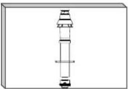 |
| Item no 081295Deflector kit | Item no 087910Weather slate (steep roof) | Item no 087372Weather slate (flat roof) | Item no 0821973Vertical roof terminal(incl. appliance adapter 60/100) |
 |  |  | 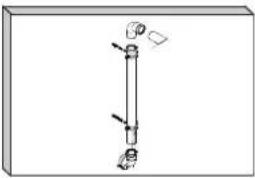 |
| Item no 081298Horizontal telescopic offset wall terminal1 | Item no 082980Horizontal straight wall terminal extended1 | Item no 081297Horizontal telescopic wall terminal1 | Item no 081294Plume management kit |
 |  |  |  |
| Item no 081284Elbow 90° (for plume management kit) | Item no 081285Elbow 60° (for plume management kit) | Item no 086004 (SF 45)Item no 086754 (SF 60)Maintenance kit A | Item no 086154Maintenance kit B |
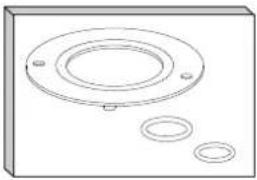 | |||
| Item no 086774Maintenance kit C | |||
INSTALLER IMPORTANT POINTS
Please read all instructions before fitting this appliance
The installer must instruct the user on the operation of the appliance, fault code diagnosis and how to reset the appliance.
The installer must hand over these installation and user instructions ensuring the Benchmark Commissioning Checklist has been completed correctly.
The attending engineer must complete the service record on the Benchmark Checklist after each service and/or replacing any parts within the appliance.
It is required under Gas Safe Regulations for the installation to be notified and to register the installation with Gas Safe, and Building Control (Gas Safe Notification).
▶ You must register the appliance with Intergas heating ltd within 30 days of the installation to validate any warranty supplied with the appliance, via post, website or MiReg if you are the installer.
When commissioning the appliance, check the gas inlet working pressure is 20mbar (NG) or 37mbar for (LPG) on P1 of the appliance gas valve. min 17mb (NG) 30mb (LPG) with all connected appliances operating at full rate)
Combustion analysis with a correctly calibrated and certificated electronic analyser is essential for safe commissioning of the appliance, this must be documented within the Benchmark commissioning checklist.
▶ A pressure reducing valve set to 3.5 bar must be fitted if the mains water supply pressure is above 5 bar, this should be located no closer than 3 metres proximity to the appliance for expansion purposes.
In areas where the water hardness is 200ppm or above, appropriate protection must be taken in accordance with BS 7593 & in line with building regulations Part L. (See Warranty Provisions on page 88, point 15).
Intergas recommend Hydroflow HS38a wired into the appliance or HS38b which can be powered separately.
The end user / home owner should be advised to keep this installation manual in a safe place, preferably near the appliance for servicing and future reference, it is a legal requirement that any attending engineer can check the validity of the Benchmark commissioning checklist (Benchmark certificate).
It is important to protect the appliance during the installation. In particular, do not allow any dust or debris to enter the flue connection at the top of the appliance.
Before operating the appliance please ensure that the copper pipework you are installing is connected to the appropriate tappings on the appliance. (Plastic pipework where appropriate must be a minimum distance of 1000mm away from the appliance connections as per BS 5955-2008).
▶ If you experience any problems please refer to the installation and commissioning guidelines within the appliance instruction manual. (If necessary, please contact Intergas Heating Ltd).
5.1 Overall dimensions

| Connections | ||
| A = Domestic cold water ∅22 (press connection) | ||
| B = Domestic hot water ∅22 (press connection) | ||
| C = Gas flow 3⁄4” ext. | ||
| D = Condensation drain ∅dn25 | ||
| w = 80 | mm Superflow 45 | |
| 105 mm Superflow 60 | ||
| W = 40 | 0 mm Superflow 45 | |
| 450 mm Superflow 60 | ||
| d = 260 | 0 mm Superflow 45 | |
| 277 mm Superflow 60 | ||
| x = 145 | mm Superflow 45 | |
| 170 mm Superflow 60 | ||
| Z = Flue / Air supply duct ∅60/100 | (concentric wall terminal) | |
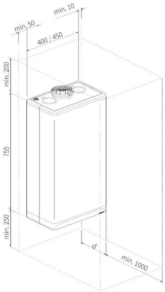
5.2 Installation location
The appliance must be installed on a solid brick wall that has sufficient strength to be able to withstand the weight of the appliance when filled with water (see Technical data).
The appliance must be connected to a 3 amp fused spur within one (1) meter of the appliance. The condense discharge from the appliance must be connected to an internal drain or waste system where possible to prevent freezing during any adverse weather conditions.
Any unheated area's i.e. a loft space or garage must be treated as external and therefore adequate frost protection measures must be taken for the appliance and any pipework etc. (see §5.3).
Make sure the appliance is easily accessible by ensuring that the adjacent clearances are adhered to.
5.2.2 Removing/installing the front panel
The front cover of the boiler must be removed to perform various maintenance activities however you must be a competent Gas Safe registered engineer before carrying out the following procedure!
Loosen both screws (1) under the boiler by using a 5 mm allen key. (They are captive and therefore will not drop out of the lower housing).
▶ Slide the front cover (2) upward and then remove it by pulling it towards you.
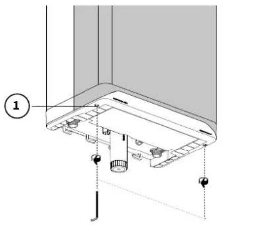

Replacing the room sealed front cover.
To replace the front panel, proceed as follows:
▶ Position the front panel (3) against the appliance and slide it downwards until it is correctly connected to the lower fascia panel.
▶ Hand tighten screws under the appliance using a 5 mm allen key (do not over tighten).

CAREFUL
This is a room sealed cover and therefore extremely important that it is fitted correctly, failure to do so could lead to products of combustion entering the room / environment where it is situated.

5.3 Installing the appliance
- Attach the wall bracket.
- Lift the appliance (2 person lift) and slide it down onto the wall bracket.
- Remove the syphon cup.
- Make sure the syphon cup is filled with water to the minimum fill level before installation.
- Replace the cup and install the supplied black flexible hose onto appliance outlet union.
- Connect the flexible hose to a 22 mm O.D solvent weld pipe. To minimize the risk of freezing the condensate pipe should be connected internally and terminate to an internal soil stack, (ref.: TB115 Gas Safe & HHIC).
- Install the flue system (see §6.4).
- Install the required pipework as per the following sections.
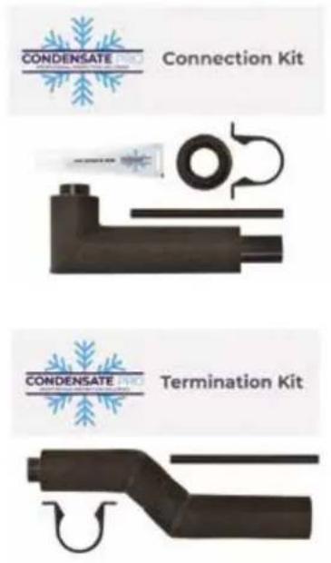
- Should the condensate be terminated to an external soil pipe, drain, rainwater system or soakaway then we only recommend the Condensate PRO system which is available from Intergas Heating Ltd via your normal stockists or heating supplies. https://condensatepro.co.uk

COMMENT
The Intergas Superflow is equipped with a appliance-specific syphon cup. Ensure that the proper version is ordered upon replacement. (Item no. 148334).

- Mount the wall bracket (ensure its level)

- Hang the appliance onto the wall bracket

- Twist and pull to remove the condense syphon cup

- Fill the condense syphon cup 5. Replace the condense syphon cup and attach the supplied flexible hose
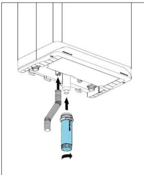


- Connect the flexible hose to the waste system via a tundish or similar.
6.1 Domestic hot water connection
▶ Flush the system clean thoroughly.
▶ Install the cold water pipe to the appliance using the supplied cold water inlet isolation valve.
▶ Install the domestic hot water pipe to the appliance using the supplied DHW outlet adapter.

6.1.1 Domestic hot water circuit resistance graph
A. Superflow 45
B. Superflow 60
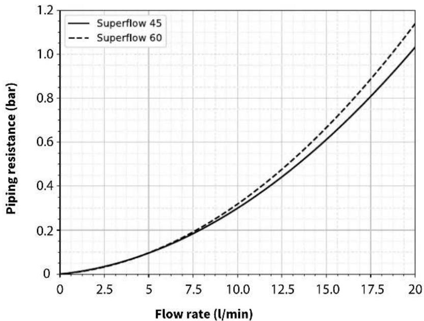
6.2 Electrical connection

CAREFUL
▶ A fused spur must be located no more than 1 metre from the appliance.
For installation within a moisture bound area i.e a bathroom or kitchen then please consult the current electrical regulations for safe separation distances.
▶ When working on the electrical circuit always isolate the 230v supply.
Should the mains power cord be replaced, this must be ordered directly from Intergas.
To gain access to the electrical connections or PCB:
Remove the front panel (see §5.2.2) and pull the PCB housing forward; then tilt it downwards.
▶ Consult the electrical schematic in §11.1 for all appliance connections.

CAREFUL
The Superflow complies with IPX4D water ingress protection. Any cables routed through the PCB housing must have grommets or glands fitted to ensure this integrity is maintained.
After the desired connections have been made, slide the PCB housing back into the appliance (until the left and right safety clips are locked) then replace the front room sealed cover on the appliance; see §5.2.2.
▶ After making the desired connections re-establish the power supply to the appliance.


6.3 Gas connection
Using the supplied gas isolation valve & fibre washer connect the preformed gas pipe to the installation supply pipework and fully tighten.
▶ Ensure that the gas pipework is correctly supported with wrap over type clips.
▶ Open the main gas valve and appliance isolation valve then purge the system of air.
Carry out a full tightness test checking all connections for any leakage (any leaks must be rectified before proceeding).
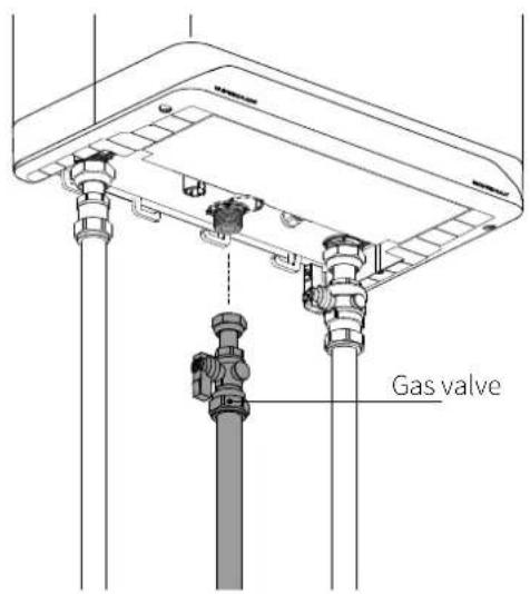

CAREFUL
Before starting any work on the appliance, always close the gas isolation valve.
The appliance is intended exclusively to be installed on a domestic gas supply with a meter that includes an ECV and pressure governor.
When pollution in the gas is to be expected a gas filter must be placed in the gas installation pipework to the appliance.
6.4 Cascade function
The cascade function allows up to 8 Tankless Water Heaters operate together to satisfy a common demand. The Leader of the cascade system will enable, disable, and modulate Followers as necessary to maintain temperature as efficiently as possible. Cascade system benefits include:
▶ Wireless communication for simplified setup.
▶ Redundancy allows for easy service and maintenance of cascaded units.
Tankless Water Heater cascade system
Tankless Water Heater cascade systems are only able to satisfy domestic hot water demands. The Leader of the cascade system will enable, disable, and modulate Followers as necessary to provide domestic hot water. Reference following table for required cascade settings.
| Parameter | Leader F | lower #1 | Follower #2 |
| Cascade Unit (C Id) 1 2 3 | |||
| Cascade Members (Clrs) 3 | -- | ||
| Cascade Function (P130) 1 1 1 |
Tankless Water Heater cascade systems should utilize an appropriately sized common header as shown. Reference the following table for minimum common domestic hot water header sizing.
| Type | Minimum Recommended DHW Header Size | ||||||
| Cold/warm water dimensions | |||||||
| 2 Units 3 Units | 4 Units 5 Units | 6 Units 7 Units | 8 Units | ||||
| Superflow 45 DN20/DN15 DN | 20/DN15 DN25/DN20 DN25/ | DN20 DN32/DN | 25 DN32/DN25 DN32/DN25 | ||||
| Superflow 60 DN20/DN15 DN | 25/DN20 DN25/DN20 DN32/ | DN25 DN32/DN | 25 DN32/DN25 DN32/DN32 | ||||
![graph TD A["Superflow (Leader)"] --> B["Cold Hot"] C["Superflow (Follower)"] --> D["Cold Hot"] E["Superflow (Follower)"] --> F["Cold Hot"] G["Red Path"] --> H["Domestic Water"] I["Blue Path"] --> J["Domestic Water"]](/content/2026/06/1399193/images/f324f43713384ee67981f2dcc4e732e18267c6542622bedf93c3099b56df2d3f.jpg)
Low Voltage Wiring
Tankless Water Heater cascade systems do not require low voltage wiring for domestic hot water operation.
Line Voltage Wiring
Electrical wiring to the unit (including grounding) must conform to local electrical codes.
Connect each unit to the grid power using the supplied appliance plug to a fused circuit with on/off switch within sight of the unit.
Cascade configuration
Cascade system configuration requires setting the cascade parameters then enabling the cascade function on each unit that will be in the cascade system. See §8.1.6 to make the following changes.
- Assign cascade unit ID (C Id) – Each unit in the cascade system must be assigned a unique cascade unit ID. The cascade unit ID of the Leader must be set to 1. The cascade unit ID of each Follower must be set to 2, 3, etc.
- Assign cascade system ID (CCA1, CCA2, CCA3) – Each cascade system must be assigned a unique cascade system ID. The cascade system ID only needs to be changed from the default setting when multiple cascade systems are present at the same location. The cascade system ID is broken up into 3 parameters, CCA1, CCA2, CCA3. The cascade system ID is CCA1 followed by CCA2 then CCA3. All units in the cascade system must be assigned the same cascade system ID number.
- Set number of cascade members (CCnt) – This parameter must be set on the Leader to the number of cascade system members.
See §8.1.6 to make the following changes.
- Enable cascade function (P130) – Enable the cascade function of each unit according to the cascade system type. The cascade function of Tankless Water Heaters can only be enabled for DHW (P130 = 1).
Cascade communication
Wireless communication can be verified in each cascade member's Information Menu. See §8.1.5 to view information item "r":
Information item "r" on the Leader will display X:YL
☐ X = Number of members connected
☐ Y = Number of configured members (CCnt)
□ L = Leader
● Information item "r" on a Follower will display:
□ C F = Follower is connected to the Leader
□ dC F = Follower is disconnected from the Leader.
Cascade adjustments
The following parameters can be used to adjust the cascade system operation after a cascade system has been configured. See §8.1.4 (Code C020) to make the following adjustments.
Rotation Frequency (P131) – Sets how often to rotate the lead stage during an extended call. If a call lasts longer than this setting, the next available stage will become the lead stage.
Firing Order (P132) – Sets the basis for calculating the firing order. The Leader will enable the unit with the least amount of usage when adding a stage. The Leader will disable the unit with the most amount of usage when disabling a stage. Usage calculation options are:
● 0 = Firing order is based on the hours of operation
● 1 = Firing order is based on fuel consumption
- 2 = Firing order is based on fuel consumption and number of ignitions
Coarse Gain (P133) – Increasing the Coarse Gain setting will cause the cascade system to ramp up faster when far below the setpoint. The cascade system will reach the setpoint quicker but is more prone to overshooting the setpoint. Decreasing the Coarse Gain setting will cause the cascade system to ramp up slower when far below the setpoint. The cascade system will take longer to reach the setpoint but is less likely to overshooting the setpoint.
Fine Gain (P134) - Increasing the Fine Gain setting will cause the cascade system to ramp up slower when near the setpoint. The cascade system may not be able to reach and maintain setpoint if the Fine Gain setting is too high. Decreasing the Fine Gain setting will cause the cascade system to ramp up faster when near the setpoint. The cascade system may oscillate above and below the setpoint if the Fine Gain setting is set too low.
DHW Staging Delay (P136) – When the Leader determines that another stage needs to be enabled to meet the DHW demand, this delay will occur before the stage is enabled.
Water side
In cascade configuration two components must be mounted in the hot water manifold: a pressure relief valve and a expansion vessel, both suited for application in domestic hot water systems.
6.5 Flue and air supply duct

For the installation of the flue and air supply duct material, see the manual included with the materials. Further technical information and specific assembly instructions are available upon request.
▶ Only stainless steel or plastic PP flue material is allowed.

▶ Make sure that the socket connections of the flue and air supply duct materials are correctly sealed. Incorrect connection of the flue and the air supply duct can lead to hazardous situations or result in personal injury. Check all flue components for tightness.
▶ Do not use screws or nails to mount the flue system as leakage can occur only use the correct support brackets at the recommended distances.
▶ Do not use any sort of grease when connecting the flue system. Use water instead. The sealing rubbers can be adversely affected when grease is applied and can also become disconnected.
Do not mix any components, materials or ways of connecting from different manufacturers as they must be approved by Intergas Heating Ltd.
6.5.1 Draft, materials and insulation
Flue materials
| Execution Diameter Material Remark | |||
| Rigid Concentric ∅100/60 mm ▶ | Stainless Steel ▶ Plastic T120 | Plastic; Approved material with lip ring sealing. | |
| Rigid single wall ∅80 mm ▶ Stain | less Steel ▶ Plastic T120 | Plastic; Approved material with lip ring sealing. | |
Air supply materials
| Execution Diameter | Material Remark | ||
| Rigid single wall ∅80 | mm ▶ Stain | less Steel ▶ Plastic T120 | Plastic; Approved material with lip ring sealing. |
6.6 Pipeline lengths
As the resistance of the flue and air supply duct pipes increases, the capacity of the appliance will decrease. The allowed decrease in capacity is a maximum of 5%.
The resistance of the air supply duct and the flue depends on the length and diameter of the piping system and all associated components. For each appliance category, the total allowed pipeline length of the air supply duct and flue is given.
The specification of the pipeline length in meters assumes ∅80 mm piping.
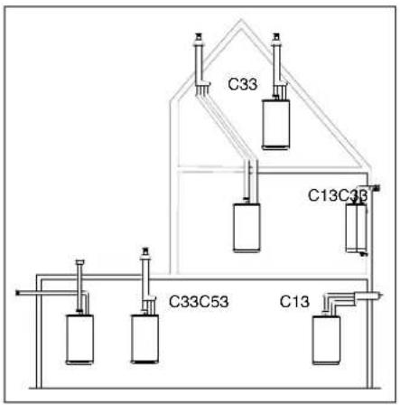
6.6.1 Replacement lengths
| Elbow of 90° R/D=0.54 m | ||
| Bend of 45° R/D=0.52 m |
Contact Intergas Heating Ltd. For further information.
6.6.2 Example calculation
| Piping Pipeline | length Total pipeline length |
| FlueAir supply duct | L1+L2+L3+(2x2m) 12 m |
Comments
The total pipeline length is: The sum of the straight pipeline lengths + the sum of all the bends which equates to a total of 12 meters as per the adjacent drawing.
▶ If the equivalent length of the air supply duct and flue gas duct combined are less than the maximum permissible quoted then the twin flue system meets the requirements at this point.
Twin Flue General assembly guide
Flue gas section assembly
▶ Connect the 80mm vertical adaptor 090767 to the appliance (optional extra).
▶ Slide the combustion outlet pipe into the adaptor on the appliance.
▶ Working from the appliance, slide each extension spigot into the previous socket and continue with each extension or bend.
The flue must be bracketed every metre and every change in direction.
▶ Each bend should have a bracket fitted either side.
▶ Connect the final section to the chosen terminal outlet.
The flue gas section must be installed with a fall of 5mm/mtr back towards the appliance.
Air supply section assembly
Remove either of the air induction caps by lifting the tab and rotating it anticlockwise by 90°.
▶ Slide the first air inlet pipe section into the appliance induction socket.
▶ Working from the appliance, slide each extension spigot into the previous socket and continue with each extension and bend.
The air duct must be bracketed every metre and every change of direction.
▶ Each bend should have a bracket fitted either side. ▶ Connect the final section to the chosen terminal outlet.
The air supply section must be installed with a fall away from the appliance*. (*Not applicable to vertical flue/air sections)


6.7 General layout of the flue
The following drawing shows possible situations schematically.

COMMENT
The following schematic drawings serve as examples and the details may differ from the actual situation.
![graph TD A["Valve"] --> B["C13"] A --> C["C33"] B --> D["C53"] C --> E["C33"] D --> F["Valve"] E --> G["Valve"] style A fill:#f9f,stroke:#333 style B fill:#ccf,stroke:#333 style C fill:#ccf,stroke:#333 style D fill:#cfc,stroke:#333 style E fill:#cfc,stroke:#333 style F fill:#fcc,stroke:#333 style G…](/content/2026/06/1399193/images/6961ac2856928bc19163f802c365f6a075474398dfa2f8d9d3d0d39e786042a9.jpg)
| Note for flue systems | ||
| Cat. Note according to CE Materials | ||
| C13 The terminal is located in the façade; the inlet for the air supply duct is located in the same pressure area as the terminal. Example: combined façade terminal | Terminal | |
| Other components | ||
| C33 The terminal is located above the roof; the inlet for the air supply duct is located in the same pressure area as the terminal of the flue piping. | Terminal | |
| Terminal at the prefab chimney | ||
| Other components | ||
| C53 Closed unit, connected to separate air supply duct and flue channels, terminated in various pressure zones. See the installation manual for the possibilities. | Intake grille | |
| Other components and exhaust cap | ||
6.7.1 Wall terminal with twin-pipe horizontal terminal C13

COMMENT
▶ PP Pipes for the connection of the air supply duct and the flue from the appliance to the wall terminal 076355 must have a diameter of ∅80 mm.
The individual flue pipe (Ø80) and/ or the internal pipe of the combi-pipe wall terminal / extension pipe must be approved by Intergas heating Ltd.
Allowed pipeline length
▶ Twin-pipe
Air supply duct and flue pipe together, excluding the length of the combi-pipe wall terminal.
| Appliance Length | |
| Intergas Superflow 45 60 m | |
| Intergas Superflow 60 40 m |
▶ Concentric
Air supply duct and combustible gas exhaust pipe together, excluding the length of the combi-pipe wall terminal.
| Appliance C13 | ||
| ∅60/100 | Intergas Superflow 45 24 m | |
| Intergas Superflow 60 14 m |


Assembly of combi-pipe horizontal terminal
▶ Create an opening of ∅130 mm at the location of the terminal.
▶ Shorten the wall terminal to the required length.
▶ Assemble the concentric flue system.
▶ Slide the wall terminal in through the opening and attach to the concentric flue.
Seal the flue through the wall with sand & cement and fit the supplied decorative covers to the opening both inside & out.
The terminal should be positioned level however any further extensions must slope back to the appliance 5mm/mtr.
The balcony kit option 086890 can be used to extend the terminal away from under the walkway, to install twist and remove the 60mm flue outlet from the existing 60/100mm terminal and discard, now install the new PMK outlet into the 60/100mm terminal, then insert the 1000mm long extension (can be cut to length) use the supplied bracket to support the PMK add then insert the new terminal end.

6.7.2 Flue terminal positions 60/100mm
Concentric Flue 60/100
The appliance utilises a special concentric flue adapter which can only be used with the elbow that is part of the horizontal flue kits.
The flue is not supplied with the appliance and should be purchased separately from your supplier. This flue may be routed to the rear, left or right of the appliance by means of the 900 degree bend, which is supplied in the flue kit.
Note
Only use a approved Intergas flue products with this appliance, which can be sourced from your appliance or Intergas stockist, with C33 type applications a vertical flue adapter will be required to connect to the appliance.
Flue Terminal position
| Terminal Position | Min.distance | |
| A | Directly below an openable window or other opening e.g. air brick | 300mm |
| B | Below gutters, soil pipes or drain pipes can be reduced to 25mm, as long as the flue terminal is ectended to clear any overhang. External flue joints must be sealed with suitable silicon seal. | 25mm |
| C | Below eaves | 200mm |
| D | Below balconies or car front roofs | 200mm |
| E | From vertical drain pipes and soil pip | 25mm |
| F | From internal or external corners | 300mm |
| G | Above ground, roof or balcony level, Terminal guards must be fitted if less than 2 metres from the ground. | 300mm |
| H | From a surface facing a terminal | 600mm |
| I | From a terminal discharging towards another terminal | 1200mm |
| J | From an opening in a carport (e.g. door, window) into a dwelling | 1200mm |
| K | Vertically from a terminal on the same wall | 1500mm |
| L | Horizontally from a terminal on the same wall | 300mm |
| M | Above an opening, air brick, opening windows, etc. | 300mm |
| N | Horizontally to an opening, air brick, opening windows, etc. | 300mm |
| P | Above roof level (to base of terminal) | 300mm |
| Q | From adjacent wall to flue | 300mm |
| R | From an adjacent opening window | 1000mm |
| S | From another roof terminal | 600mm |
| - | Distance to a boundary, unless it will cause a nuisance.BS 5440:Part1 recommends that care should be taken in sitting terminal in relation to boundary lines. A PMK or Deflector may be fitted. | 600mm |
| T | Terminals adjacent to windows or openings on pitched and flat roofs:The flue should not penetrate this area. | 2000mm |
| T1 | 600mm | |
| T2 |

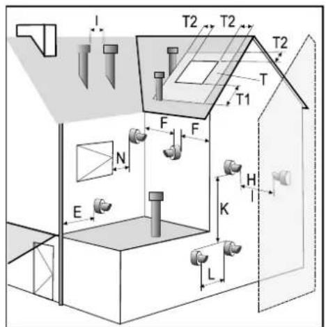
Note
Intergas cannot be held responsible for atmospheric conditions when siting flue terminals it is the installers responsibility to ensure products of combustion cannot enter the building under adverse or normal weather conditions.

CAUTION
Once the flue has been installed and the appliance commissioned, the installer should observe the plume direction. Particular attention should be drawn to plume vapour re-entering the appliance via the air intake. If this occurs, it is highly possible the flue is fitted within a negative pressure area and therefore a plume management kit (PMK) must be fitted.
To reduce the telescopic flue length further:
Separate the telescopic flue, with the terminal end, mark the length required (min. 130mm) for the terminal and cut square, taking care not to damage the tubes.
Remove any burrs and chamfer the outer edge of the tubes to assist ease of connection and prevent seal damage. The aluminum tape is not required when reducing the terminal to a single section.
6.7.3 PMK terminal positions 60mm

| Terminal Position | Min. distance | |
| 1 | 600mm distance to a boundary or surface facing a boundary, unless it will cause a nuisance. BS5440:Part1 recommends that care is taken when siting terminals in relation to boundaries.Adjacent to a boundary line. | 600mm300mm |
| 2 | Internal/external corners. The air intake clearance can be reduced to 150 mm providing the flue exhaust outlet has a 300 mm clearance. | (Air) 150mm(Exhaust) 300mm |
| 3 | The flue cannot be lower than 1,000 mm from the top of the light well due to the build up of combustion products. | 1000mm |
| 4 | 200 mm between air intake and facing terminal. | 1200mm |
| 5 | Clearance no less than 200 mm from the lowest point of the balcony or overhang. | 200mm |
| 6 | 200 mm from an opening in a car port on the same wall i.e. door or window leading into dwelling. | 300mm |
| 7 | Balcony kit option.Using a Plume Management Kit the air intake measurement can be reduced to 150 mm providing the flue exhaust outlet has a 300 mm clearance. Plume kits running horizontally must have a 10° fall back to the appliance for proper disposal of condensate.For details on specific lengths see relevant applianceTechnical & Specification information. | (Air) 150mm(Exhaust) 300mm |
| 300 mm minimum clearances to a opening e.g. window.However the minimum clearance to an opening in direction that the plume management is facing, must be increased to 1,500 mm.Where the flue is less than 150 mm to a drain pipe and plume re direction is used the deflector should not be directe-d towards the drainpipe. |

Installations in car ports are not recommended
6.7.4 Roof terminal with combi-pipe vertical terminal C33

IMPORTANT
PP Pipes for the connection of the air supply and the flue ducts from the appliance to the vertical Terminal must have a diameter of ∅80 mm.
▶ All the flue pipe components and any terminal used must must be approved by Intergas heating Ltd.
▶ Intergas Twin-pipe vertical terminal (086883)
Permissible equivalent pipeline length
▶ Twin-pipe
Air supply duct and flue pipe combined, excluding the length of the Twin-pipe wall terminal or the twin-pipe wall terminal.
| Appliance Length | |
| Intergas Superflow 45 60 m | |
| Intergas Superflow 60 40 m |
▶ Concentric
Air supply duct and combustible gas exhaust pipe, excluding the length of the Twin-pipe wall terminal.
| Appliance C33 | ||
| ∅60/100 | Intergas Superflow 45 24 m | |
| Intergas Superflow 60 14 m |
Assembly of twin-pipe vertical terminal
On a sloping roof, install a pitched weather slate (art no. 087910) then slide the terminal through the slate and adjust to vertical. Seal around the storm collar and adjusting section onto the slate with a suitable clear silicone sealant, that is specifically designed for external conditions (not supplied).
On a flat roof, install a flat roof weather slate (art no. 087372) then slide the terminal through the slate and ensure it is vertical. Seal around the storm collar using a suitable clear silicone sealant, that is specifically designed for external conditions (not supplied).
▶ Install the 80/80 twin pipe manifold onto the bottom of the vertical terminal and secure everything in place with the supplied bracket.


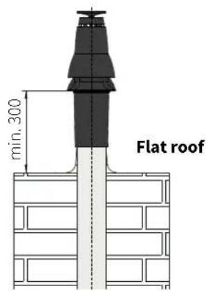
6.7.5 Roof terminal and air supply duct from the façade C53

IMPORTANT
The air supply duct in the facade must have an Intergas intake grille (part number 082856).
All the flue pipe components and any terminal used must must be approved by Intergas heating Ltd.
Permissible equivalent pipeline length
Air supply duct and flue pipe combined, excluding the length of the terminal section.
| Appliance Length | |
| Intergas Superflow 45 60 m | |
| Intergas Superflow 60 40 m |
Assembly of horizontal air supply duct
The air supply can be made in an arbitrary location in the façade.
▶ At the location of the supply, core an opening of ∅90 mm.
▶ Shorten the air supply duct pipe to the desired length out of the wall so the cover plate can sit flush.
▶ Attach the Intergas air intake terminal to the wall using the 4 x screws and plugs provided
▶ Slide the air supply onto the terminal and attach the decorative plate to the internal plaster wall face.
The air supply duct MUST BE angled away from the appliance to prevent rain entering the appliance during adverse weather conditions.
Assembly of vertical flue terminal
On a sloping roof, install a pitched weather slate (part number 087909) then slide the terminal through the slate and adjust to vertical. Seal around the storm collar and adjusting section onto the slate with a suitable clear silicone sealant, that is specifically designed for external conditions (not supplied).
On a flat roof, install a flat roof weather slate (part number 075333) then slide the terminal through the slate and ensure it is vertical. Seal around the storm collar using a suitable clear silicone sealant, that is specifically designed for external conditions (not supplied).
The terminal must be at least 500 mm above the roof surface secure everything in place with the supplied bracket.

6.7.6 Clamping the flue system (twin and concentric)

IMPORTANT
These regulations are typical for both concentric and twin flue systems.
The flue system must be secured to a solid structure.
The flue system should have a continuous fall back to the appliance.
▶ Only use Intergas approved brackets.
▶ Every bend or change of direction must be secured by using the approved bracket (excluding the appliance bend). If the length of the pipes before and after the first elbow, are no more than 250mm, a support bracket must be used and positioned on the elbow! (See illustration D)
▶ Every extension must be secured per metre with a bracket.
This bracket must be clamped around the pipe ensuring free movement for expansion and contraction purposes.
▶ Make sure bracket is locked correctly depending on its location i.e. position "A" = pipe location position "B" = elbow location.
A = bracket on pipe
B = bracket on elbow

Maximum distance between brackets
| Flue system\Orientation | Horizontal/non-vertical | Vertical |
| Safe-PP 1000 mm 2000 mm | ||
| Concentric 1000 mm 2000 mm |
▶ Distribute the length between brackets evenly.
▶ Each flue system has to contain at least 1 bracket.
The distance between the appliance and the first bracket must not be more than 500 mm.

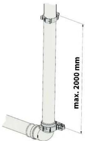


COMMENT
These examples are typical for both twin and concentric flue bracket positioning.


6.7.7 Twin flue terminal positions
Flue Terminal positions


| Terminal Position | Flue Min. Distance | Air Min. Distance | |
| A | Directly below to an openable window or other opening e.g. air brick | 300mm 50mm | |
| B | Directly above an opening | 300mm 50mm | |
| C | Horizontally to an opening 300mm 50mm | ||
| D | Below gutters, soil pipes or drain pipes | 75mm 75mm | |
| E | Below eaves | 200mm 50mm | |
| F | Below balcony or car port roof, Terminal guards must be fitted if less than 2 metres from the ground | 200mm 50mm | |
| G | Above ground or balcony or roof, Terminal guards must be fitted if less than 2 metres from the ground. | 150mm 25mm | |
| H | From internal or external corners or to boundary | 300mm 50mm | |
| I | Above ground or balcony or roof, Terminal guards must be fitted if less than 2 metres from the ground. | 300mm 50mm | |
| J | From a surface or boundary facing a terminal 600mm 100mm | ||
| K | From a terminal discharging towards another terminal | 1200mm 100mm | |
| L | From an opening in a car port (e.g. door, window) into a dwelling | 1200mm 100mm | |
| M | Vertically from a terminal on the same wall | 1500mm 1500mm | |
| N | Horizontally from a terminal on the same wall | 300mm 300mm |
7.1 Using the control panel
Gently touch and release the white power LED symbol

Power on / power off mode.
Gently touch and hold the white power LED symbol for 2 seconds

7.2Appliancepreparation
7.2.1 Domestic hot water facility
▶ Put the plug of the appliance in a wall outlet. The appliance is recognisable in its switched-off setting by the display of the white power LED and a [-] on the right display.
▶ Open the cold water main isolation valve under the appliance.
▶ Vent the heat exchanger and the pipework by opening all domestic hot water outlets.
Leave the outlets open until all the air has dispersed from the system then close each one in turn.
▶ Check all connections and pipework for any leaks, repair any found as required.
With the appliance switched on run a domestic hot water outlet and check the appliance is operating correctly (Only after the Gas supply has been commissioned correctly).
7.2.3 Gas supply
▶ Purge the gas installation pipework to ensure no air remains.
▶ Complete a full tightness test any leaks must be repaired and retested prior to operating the appliance.
▶ Check the inlet working pressure via P1 at maximum output (H) which must be ≥ 17mB with all other appliances at full rate and gas-air control at minimum output to ensure the correct CO 2 levels (see §8.3).


(P1) Inlet pressure measurement test point
7.3 Commissioning procedure
After the preparations are completed successfully, the appliance can be commissioned by following the below procedure for this:
▶ Switch on the appliance by touching just above the power LED and holding this for 2 seconds.
▶ If desired, set the domestic hot water temperature and/or DHW comfort function; see §8.1.2.
▶ Check the domestic hot water facility for correct operation by opening an hot water tap.
▶ Instruct the end user about filling and venting and the operation of the heating and the domestic hot water.
▶ Hand the installation instructions and warranty registration card to the customer / end user.
The combustion readings must be checked at high rate & low rate to ensure they are within tolerance (they must only be adjusted at low rate if required) see §9.9.


7.4 Shutting down the appliance

CAREFUL
▶ Only drain the appliance and the system if the mains voltage has been interrupted and there is a chance of freezing.
▶ Switch the power off to the appliance.
▶ Remove the 3 amp fuse from the wall spur.
▶ Turn off the gas isolation valve under the appliance.
▶ Drain the appliance completely.
▶ Turn off the mains cold water supply isolation valve under the appliance.
Drain the appliance by disconnecting the domestic hot water connections under the appliance and the pipework at the lowest point.

The operation of the appliance can be influenced by the various
(parameter) settings within the PCB. Access of these menus, can be made and modified via the touch screen display.
NOTE. Some of the settings are only accessible after entering the installer's code(see §8.1.3 and §8.1.4).

The appliance has a touch screen display panel. Symbols will illuminate when they are operable and they will be extinguished when they are no longer available.

▶ 8.8.8.8: Left display / Desired temperature in °C / Fault code / Time / Information menu
▶ : - (Minus) button
+: + (Plus) button
Appliance operating (burner is switched on)
Power LED
: DHW demand / DHW comfort setting / Adjusting domestic hot water setting
▶ : Service button
: Enter button
▶ 8.: Right display / operational code
NB: The values shown on the various displays in this installation manual serve as an example and may differ from the current situation.
8.1 Navigate the settings
There are several menus to navigate through that are accessible via the touch screen panel.
The following menus are available:
▶ Main menu
First line menu from which all other menus are accessible.
▶ Domestic hot water menu
Menu in which the domestic hot water-related settings can be modified or set.
▶ Service menu
Menu in which the test programs can be activated and the (installer's) parameters can be modified (installer's code required).
Info menu
Menu in which the current appliance characteristics can be obtained.
8.1.1 Main menu
The main menu is accessible by gently tapping just above the power LED. The main menu can be viewed with the appliance switched on or switched off on the fascia (230v power must be switched on). The main menu will be displayed for 1 minute, without intervention, it will then return to its original status.
The following symbols will light up:
The domestic hot water symbol
The Service symbol
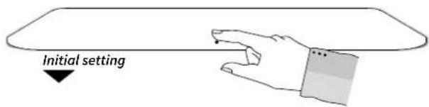

Main menu
8.1.2 Domestic hot water menu
The domestic hot water menu has 2 settings and is accessible by gently tapping on the Domestic Hot Water symbol from the main menu.
Within the domestic hot water menu:
The domestic hot water temperature can be adjusted
The DHW comfort function can be altered
The following symbols will illuminate:
The Minus symbol
The Plus symbol
The Enter symbol
The left section will illuminate and will display the current preset domestic hot water temperature.
By tapping on the domestic hot water symbol once you enter the temperature adjustment menu, by tapping on the DHW symbol again, you enter the comfort setting menu.
To adjust the domestic hot water temperature setting:
- Tap the Domestic Hot Water symbol 🔒. The default temperature (55°C) is displayed on the left side of the fascia.
- Using the Plus and Minus buttons, set the desired temperature (for example, 60°C).
- Tap the Enter button ↩ to confirm (or wait 30 seconds). A P appears on the right display (all other symbols are extinguished), which means the setting has been stored.
- The display returns to the main menu.
For the quick supply of domestic hot water, the appliance is equipped with a DHW comfort function. This has the following settings:
On:
The DHW comfort function is permanently on. The heat exchanger will continuously maintain the preset temperature.
Eco:
The DHW comfort function of the appliance will self learn. The appliance will adapt itself to the pattern of usage for domestic hot water. This means that the heat exchanger will not maintain temperature during the night or with long absences.
▶ Off:
The heat exchanger is not preheated, the appliance will now act as a normal appliance and only operate when there is a demand for DHW. If there is no need for a quick supply of domestic hot water, the DHW comfort function can be switched off.
To adjust the DHW comfort function:
- Tap the Domestic Hot Water button 2x 🔒. The preset comfort setting is displayed on the left of the fascia.
- Using the Plus and Minus symbols, set the desired comfort setting (for example, P-On).
- Tap the Enter button ↗ to confirm (or wait 30 seconds). A P appears on the right display (all other symbols are extinguished), this confirms the chosen setting has been stored.
- The display returns to the main menu.


8.1.3 Service menu
The service menu is accessible by first touching the display just above the power symbol then press and hold the service symbol for 2 seconds.
Within the service menu:
▶ the test programs can be activated
▶ access to the (installer's) parameters
▶ access to the info menu
▶ acces to the casade menu
The following symbols will illuminate:
The Minus symbol
The Plus symbol
The Enter symbol
The Domestic Hot Water symbol will be extinguished.
Test programs
The appliance has a test mode facility within the PCB. By activating a test program, the appliance will operate with a fixed fan speed without any of the control functions intervening however, the safety functions remain active.

The test programs can only be activated if there is a demand for domestic hot water, with sufficient flow to allow for the provision of the amount of heat generated.
The following test programs are available:
| Program ‘L’Burner on at minimum output.Press and together once. |
| Program ‘H’Burner on at maximum output.Press and twice. |
| Switching off test programPress + and together once. |
To activate the 'L' test program:
- Press the Service symbol 🔊 and the Minus button once at the same time. The symbol 'L' will appear on the right of the display.
- Tap the Minus button and the Plus button at the same time to terminate the program.
To activate the 'H' test program:
- Press the Service symbol and the Plus symbol twice at the same time. The symbol 'H' will appear on the right of the display.
- Tap the Minus symbol and the Plus symbol at the same time to terminate the program.
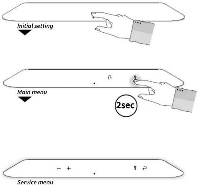


8.1.4 Parameters
| Parametre | Setting | Setvalue Description/Setting range |
| POTPO70 | Set maximum DHW capacity 100 20% to 100% | |
| POTHPOT | Number ECO days 7 0 to 10 days |
(Installer's) parameters
The (installer's) parameters of the burner controller are factory-set according to the above table.
These parameters can only be modified using the installer's code.
The installer's code is shown on the left display and is preceded by the letter .
The parameters are also shown on the left display and are preceded by the letter P.
To modify a parameter:
(for example, modify parameter 74 from 7 to 3)
- Tap the Service button and the Enter button at the same time. The Enter button is extinguished and all other buttons remain on. The code C000 appears in the left display.
- Using the Plus button + and the Minus button -, set the installer's code (C015) and tap on the Service button 🔊. Parameter P070 will now be shown on the left display.
- Using the Plus button + and the Minus button -, set the desired parameter (in this example, P074) and tap on the Service button 🔒. The set value of the relevant parameter will be shown on the left display (in this example, "7").
- Using the Plus button + and the Minus button -, set the desired value of the parameter (in this example, 3).
- Tap the Service button . Repeat Steps 3 and 4 to set any additional parameters.
- Tap the Enter button ➕ to confirm. A P appears on the right display (all other buttons are extinguished), which means the settings have been stored.
- The display returns to the initial setting and is ready for any heat demand.

By tapping just above the power LED during a parameter modification, the modification procedure is ended without the parameter modification being saved. The display returns to the initial setting and is ready for any heat demand.
![graph TD A["Service menu"] --> B["C000 - + . 1"] B --> C["C015 - + . 1"] C --> D["P070 - + . 1 2"] D --> E["P074 - + . 1 2"] E --> F["7 - + . 1 2"] F --> G["3 - + . 1 2"]](/content/2026/06/1399193/images/b4ab2d24452a0501e73c1ba26e11e1d8a56c2484cdc47b1993ce56f5c979d1e4.jpg)
8.1.5Infomenu
The info menu is accessible by touching the Service symbol from the service menu and holding it for 2 seconds.
(Note if you are not in the service menu you will need to touch the service symbol and hold it for 2 x 2 seconds).
Via the info menu certain appliance operational statistics can be viewed.
The following symbols will illuminate:
The minus symbol
The plus symbol
Respectively the right and left display will display the relevant infocode and its corresponding value.
By tapping the plus symbol and the minus symbol the following characteristics are displayed in succession:
Left display Right display
▶ Ionisation current in µ A
▶ Domestic hot water flow in litres/minute b
▶ Appliance output in kW F
▶ Pump RPM in % (N/A)
▶ Last fault code
▶ Current PCB Firmware version =
▶ Current Firmware version DSP processor
▶ Temperature sensor S0 (Heat exchanger)
▶ Temperature sensor S1 (N/A)
▶ Temperature sensor S2 (N/A)
▶ Temperature sensor S3 (DHW hot)
▶ Temperature sensor S4 (DHW cold)
▶ Temperature sensor S5 (Flue gas) 5
▶ Temperature sensor S6 (N/A) 6
▶ Temperature sensor S7 (Cylinder sensor option)

Info menu
Ionisation current
Info menu
DHW flow
Info menu
Appliance output
Info menu
Last fault code
Info menu
Current PCB firmware version
Info menu
Current Firmware version DSP processor
Info menu
Temperature sensor S0 (Heat exchanger)
Info menu
Temperature sensor S3 (DHW hot)
Info menu
Temperature sensor S3 (DHW cold)
Info menu
Temperature sensor S5 (Flue gas)
Info menu
Temperature sensor S7 (Cylinder sensor option)
8.1.6 Cascade menu
The cascade menu is accessible by tapping the Service button and the Enter button at the same time from the service menu.
To access the cascade parameters:
- Using the Plus button and the Minus button, set the installer's cascade code (C035) and tap on the Service button. Parameter C Id will now be shown on the left display.
- Using the Plus button and the Minus button to cycle through the parameters.
- Tap on the Service button to adjust the selected parameter.
- Using the Plus button and the Minus button, set the desired value of the parameter.
- Tap the Service button . Repeat Steps 3 and 4 to set any additional parameters.
- Tap the Enter button ➕ to confirm. A P appears on the right display (all other buttons are extinguished), which means the settings have been stored.
- The display returns to the initial setting and is ready for any heat demand.
![graph TD A["Service menu"] --> B["C000 - + 1"] B --> C["C035 - + ."] C --> D["C1d - + 1 2"] D --> E["CCnt - + ."] E --> F["4 - + 1 2"] F --> G["4 - + ."] G --> H["C1d - + . 1 2"]](/content/2026/06/1399193/images/c87855b93f2eac694554389489becdef53064db3c8c0e56b07efac2b4e7fbc58.jpg)
Cascade parameters - Access code C035
| Parameter | Description Default Range/Options | ||
| CId Cascade | Unit ID 1 1 - 8 | ||
| CCA1 | Cascade Systems ID | 255 | 0 - 255 |
| CCA2 | Cascade Systems ID | 255 | 0 - 255 |
| CCA3 | Cascade Systems ID | 255 | 0 - 255 |
| CCnt | Cascade Members | 1 1 - 8 | |
8.2 Conversion to another gas type

IMPORTANT
▶ Only qualified competent gas safe registered engineers may work on the appliance and Intergas training is recommended before undertaking the following procedure.
If the appliance is connected to a different gas type than originally
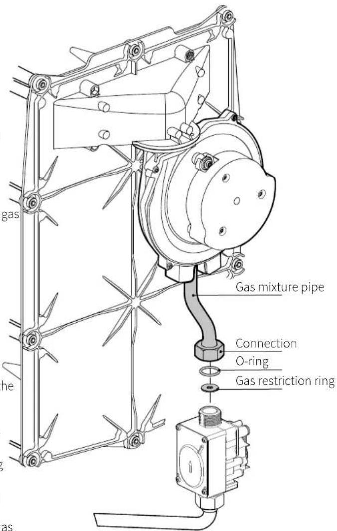
set by the manufacturer, then the gas restriction ring must be replaced. Conversion kits for other gas types are available to order.
Changing / replacing the gas restriction ring
▶ Switch off the appliance and isolate the power supply.
▶ Close the gas isolation valve supplied with the appliance and test to ensure there is no let-by (the valve must be replaced if faulty or letting by before continuing with the conversion).
▶ Remove the room sealed front casing of the appliance.
▶ Disconnect the union above the gas valve and rotate the gas mixture pipe clear of the gas valve.
▶ Replace the O-ring seal and gas restriction ring with the ones supplied in the new conversion kit (ensuring they are the correct type for the gas category being supplied to the appliance).
▶ Reassemble in reverse order.
▶ Open the appliance gas isolation valve.
▶ Check the gas connections prior to the gas valve for tightness.
▶ Reestablish the power to the appliance.
▶ Briefly operate the appliance checking all unions above the gas valve for tightness with a calibrated electronic gas leak detector or leak detection fluid.
Now check the adjustment of the gas/air proportion (see §8.4 to §8.4.3).
Place the supplied, fuel category sticker, over the existing one on the gas valve.
▶ Place the second supplied, fuel category sticker near the data plate under the appliance.
After adjusting the mixture correctly and completing all gas safety checks, as per regulation 26(9), then replace the room sealed front cover to check the flue integrity at full gas rate ("H" in the display).

IMPORTANT
▶ Only qualified competent gas safe registered engineers may perform adjustments to the gas/ air ratio control on the gas valve.
The gas/air control valve is factory set to optimise combustion for the gas type used. The gas type (Natural Gas or LPG) is detailed on the data plate situated under the appliance. The appliance must only be operated with the gas category specified on the aforementioned data plate.
The appliance may optionally be converted to another gas type using a conversion set. See §8.2.
For the correct gas restriction ring, see the table below.
Table 1: Gas restriction rings
| Intergas Superflow appliance type | Insert number | Gas category | |
| Natural gas G20 20 mbar | LPG G31 30 & 50 mbar | ||
| 45 456 550 440 | |||
| 60 375 660 535 | |||
A proper operation of the gas air control can be established by measuring the flue gases directly above the appliance using an analyser probe of a flue gas analyser. The measurement takes place at high and low fire (for this, see §8.4.1 and §8.4.2). Any deviation can be corrected solely at low fire by setting the gas valve anew (see §8.4.3).
IMPORTANT

▶ Inspection of the gas/air control valve must be carried out with room sealed casing opened.
The measurement must be performed based on O2 ; in other words, the flue gas analyser must have an O2 sensor.
The deviation of the flue gas analyser may be a maximum of ±0.3% (based on O2 ).
▶ Any extreme weather conditions i.e. high winds can influence the results of the test.
▶ Any readings that are out of tolerance during maximum output cannot be corrected by adjusting the gas valve. The appliance must be meticulously inspected for gas quality / type, correct components used (especially the gas restriction ring and the fan including venturi).
When replacing components and/or converting to another gas type, the operation of the gas air control valve must always be checked.
8.4 Inspection of gas air control
8.4.1 Measuring flue gas at high fire
A. Switch off the appliance.
A dash – will appear on the right display and the central heating pressure will be visible on the left display.
B. Remove the room sealed cover of the appliance by loosening the 2x 5mm Allen key screws (1) and then sliding it up and forward (2).
C. Remove the cap of the flue gas sampling test point (3) on the appliance connector on top of the appliance.
D. Place the sampling probe of the calibrated electronic flue gas

IMPORTANT
▶ Make sure that the flue gas analyser is calibrated. The start-up procedure of the flue gas analyser must be completed before the analyser probe is placed in the flue gas measurement point.
The analyser probe must completely seal off the flue gas measurement point to provide a reliable measurement.
The end of the analyser probe must be located entirely in the flue gases (middle of the flue gas pipe).
analyser into the flue gas sampling point (3).
E. Switch on the appliance by touching above the power light for 2 seconds.
F. Switch on the appliance to maximum output. To do this, hold the Service symbol 🎨 and at the same time tap the Plus symbol + twice until the capital letter H appears on the right display.

IMPORTANT
▶ Make sure that the capital letter H appears on the right display. This provides assurance that the appliance is operating as maximum load.
G. Wait until the readout of the flue gas analyser is stable (at least 10 minutes).
H. Note the measured CQ(H) value. CO2(H) = measured maximum output CO2 value
1. Check according to Table 2 whether the measured maximum output CO₂(H) % is between the indicated upper and lower limits.
J. The flue gas performance measurement must also be checked at minimum output (see §8.4.2).


Table 2: Allowed CO₂(H) limits at maximum output (open casing)
| Value limits | Gas category | |
| Natural gasG20 | LPGG31 | |
| CO2 [%] CO | 2 [%] | |
| Upper limit 9.6 10.8 | ||
| Lower limit 8.6 9.8 | ||

IMPORTANT
▶ Any readings that are out of tolerance during maximum output cannot be corrected by adjusting the gas valve. The appliance must be meticulously inspected for gas quality / type, correct components used (especially the gas restriction ring and the fan including venturi).
8.4.2 Measuring flue gas at low fire
Before measuring the flue gases at minimum output, the measurement at maximum output must be completed.
See §8.4.1.
The measured CO2 (H) % at maximum output is important to determine equilibrium, this must be completed before checking the minimum output %.
A. Switch on the appliance at minimum output. To do this, tap simultaneously the Service symbol and the Minus symbol — until the capital letter L appears on the right display.
B. Wait until the readout of the flue gas analyser is stable (at least 10 minutes).
C. Note the measured CO2(L) value. CO2(L)= measured minimum output CO2 value
D. Check according to Table 3 whether the measured minimum output CO₂(L) value is between the indicated upper and lower limits.
E. If the minimum output measurement falls outside the limits given in Table 3a or 3b, continue at §8.4.3 to adjust the gas valve. If the setting is correct, continue to Step F.

The C2 opper limit is the CO2(H) value that was noted during the maximum output measurement. (See §8.4.1)
Table 3: Allowed CO₂(L) limits at minimum output (open casing)
| Value limits | Gas category | |
| Natural gasG20 | LPGG31 | |
| CO2 [%] CO | 2 [%] | |
| Upper limit | CO2(H) | CO2(H) - 0.3 |
| Lower limit 8.4 9.4 | ||


IMPORTANT
The gas air control is correctly set if the measured value at minimum output falls within the indicated upper and lower limits. Adjustment of the gas air control is not necessary in this case. The setting at minimum output must be adjusted using the method described in §9.10.3 if the measured value is outside the indicated limits.

Example (Natural gas G20)
During maximum output a C2(H) value of 9.0 % has been measured. In this case the CO2(L) value at minimum output must be 8.7 ± 0.1% (= 0.5x CO2(H) + 4.2) as stated in the table 4 and 5. When measuring the gas-air ratio at minimum output (L) and the value is out of this range then it must be adjusted, as described in §9.10.3.
A. Reattach the room sealed cover and tighten the 2 x 5mm Allen screws by hand (do not overtighten).
Check the CO value at minimum output. The maximum allowed CO measurement value is 160 ppm.
B. Switch the appliance to maximum output. To do this, hold the Service symbol and at the same time tap the Plus symbol twice + until the capital letter H appears on the right display. Check the CO value at maximum output. The maximum allowed CO measurement value is 160 ppm.
C. Switch off the appliance.
D. Remove the probe of the flue gas analyser from the flue gas sampling point and carefully replace the cap on the adapter above the appliance.
E. Switch on the appliance again.
F. Check the gas integrity of the flue gas sampling point.
G. Carry out a flue integrity test via the air sampling point on the appliance adaptor or bend (the appliance must be set to a maximum output NH).
O2 readings must be between 20.6 & 20.9% otherwise check the flue system and flue seals for damage.
8.4.3 Minimum output correction
Before the minimum output correction is performed, the maximum output and minimum output measurements must be completed. The measured CO2(H) value at maximum output is important for determining the correct value for the setting at minimum output (see §8.4.1 and §8.4.2).
A. Remove the dust cap of the gas valve so that the adjustment screw is accessible.
B. Switch on the appliance at minimum output. To do this, tap simultaneously the Service button 🔒 and the Minus button — until the capital letter L appears on the right display.
C. Wait until the readout of the flue gas analyser is stable (at least 3 minutes).
D. Measure the CO2(L) value.
E. Using the adjustment screw B, set the correct CO₂(L) value. For the correct CO₂(L) setting value, see Tables 4a, or 4b.
F. Re-attach the cover screw of the gas valve so that the adjustment screw is sealed.
G. Check the measurements at both maximum output and minimum output noted in §8.4.1 and §8.4.2 (start with Step F in §8.4.1) to ensure the correct flue gas emission levels are obtained.
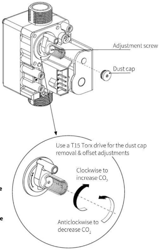

▶ Select the correct table depending on the applicable gas category:
4a: natural gas (G20) 4b: LPG 3P (G31)
The maximum output measurement value is important for a correct adjustment. This measurement value was noted during the maximum output measurement CO 2 (H) (see §9.10.1).
▶ Turning the adjustment screw to the right increases CO2 .
Turning to the left decreases CO2 .
▶ Turn the adjustment screw with small steps and wait after each turn until the measurement stabilises.
Table 4a: Checking CO₂(L) levels for Natural gas (open casing)
| Natural Gas G20 (20 mbar) | |
| Measured value at maximum output(see §9.10.1) | Setting value minimum output |
| CO2(H) [%] CO | 2(L) [%] |
| 9.6 9.0 ± 0.1 | → |
| 9.4 8.9 ± 0.1 | → |
| 9.2 8.8 ± 0.1 | → |
| **9.0 8.7 ± 0.1 | → |
| 8.8 8.6 ± 0.1 | → |
| 8.6 8.5 ± 0.1 | → |
Table 4b: Checking CO₂(L) levels for LPG (open casing)
| LPG G31 (37 mbar) | |
| Measured value at maximum output(see §9.10.1) | Setting value minimum output |
| CO2(H) [%] CO | 2(L) [%] |
| 10.8 10.5 ± 0.1→ | |
| 10.6 10.3 ± 0.1→ | |
| 10.4 10.1 ± 0.1→ | |
| 10.2 9.9 ± 0.1→ | |
| 10.0 9.7 ± 0.1→ | |
| 9.8 9.5 ± 0.1→ | |

**Example (when using natural gas G20)
During maximum output, a C2(H) level of 9.0% is measured. In this instance a minimum output CO2 value must be 8.7 ± 0.1% .
9.1 Fault codes
Viewing fault codes
If the appliances PCB detects a fault, this is indicated by a flashing service symbol 📋 on the display. A fault code, such as F004, is illuminated on the left display.
The service symbol remains flashing until the appliance has reset or where required the faulty component has been replaced.
Resetting the appliance
The appliance can be reset by touching the flashing Service button ⚙ and holding it for 2 seconds. If the fault code reoccurs an Intergas trained engineer should be requested.

Using the fault code table below to establish the cause of the issue before attempting to reset the appliance. NOTE: A reset is not possible when a component is outside its tolerance values.
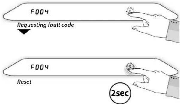
The following fault codes can be established:
| Fault code Description Possible cause / solution | ||
| F000F000 | Sensor S0 is defective. | ► Replace heat exchanger sensor S0. |
| F002F002 | Temperature too high during DHW demand. | ► Check domestic hot water sensor wiring S3 for breakage/shutdown.► Check whether the domestic hot water sensor S3 has been properly connected.► Check for the correct operation of domestic hot water sensor S3.► Replace domestic hot water sensor S3. |
| F003F003 | Flue gas temperature is too high. | ► Check heat exchanger for contamination.► Check the heat exchanger for wear and tear. |
| F004F004 | No flame during start-up. | ► Gas valve is faulty or no power from PCB (24v dc pins 1 & 5).► Gas inlet working pressure below 17mbar (20mbar recommend)► Condensation drain is blocked or frozen.► Check ignition module, ignition pin, lead or spark gap.► No power to Ignition unit.► Poor earth to appliance or ionisation pin. |
| F005F005 | Flame failure during normal operation. | ► Condensation drain is blocked or frozen.► Gas inlet working pressure below 17mbar (20 mbar recommend)► Check ignition module, ignition pin, lead or spark gap.► Check adjustment of gas valve (See §9.10.1).► Check the flue integrity for possible re-circulation or blockages► Poor earth to appliance or ionisation pin. |
| F006F006 | Flame simulation. | ► Replace faulty gas valve.► Replace faulty PCB. |
| F007F007 | No or insufficient ionisation current. | ► Check ionisation/ignition pin is clean and correctly located.► Check ionisation/ignition pin wiring is connected not damaged.► Replace ionisation/ignition pin. |
| F008F008 | Incorrect fan speed detected | ► Check fan wiring.► Check and/or replace fan assembly.► Replace PCB. |
| F009F009 | Internal fault in burner controller. | ► Replace burner controller. |
| F009F009 | Internal PCB fault. ▶ Replace PCB. | |
| F010, F011F010, F011 | Heat exchanger Sensor S0 fault. | ▶ Check wiring to heat exchanger sensor S0 (ensure its connected and not damaged).▶ Check heat exchanger sensor S0 resistance values are correct.▶ Check for the correct location of heat exchanger sensor S0.▶ Replace heat exchanger sensor S0. |
| F012F012 | Flue gas sensor fault S5. | ▶ Check wiring to flue gas sensor S5 (ensure its connected).▶ Check flue gas sensor S5 resistance values are correct.▶ Check for the correct location of flue gas sensor S5.▶ Replace flue gas sensor S5. |
| F014F014 | Heat exchanger sensor S0 mounting fault. | ▶ Heat exchanger sensor S0 is not mounted correctly. Attach the sensor correctly. |
| F015F015 | DHW sensor S3 mounting fault. | ▶ Domestic hot water sensor S3 is not mounted correctly. Attach the sensor correctly. |
| F017F017 | Bypass valve fault. | ▶ Check the wiring of bypass valve for breakage/shutdown.▶ Disconnect the appliance from electricity (plug out of the wall socket). Plug the plug back into the wall socket and restart the appliance▶ Replace bypass valve. |
| F018F018 | Flue and/or air supply duct is blocked/restricted. | ▶ Check the flue and the air supply duct including seals or gaskets.▶ Clean the flue and/or the air supply duct. |
| F019F019 | Appliance memory module fault. | ▶ Check BMM wiring or connector for damage.▶ Replace BMM. |
| F021F021 | Short circuit of outdoor weather compensation sensor S6. | ▶ Check wiring to outdoor sensor and ensure its connected correct and not damaged.▶ Check the outdoor sensor resistance values are correct.▶ Replace the outdoor sensor. |
| F023F023 | Reset error. | ▶ Check the reset button for unintentional operation (e.g. cleaning of control panel).▶ Replace the PCB. |
| F025F025 | Gas valve fault. | ▶ Check the gas valve wiring, coil resistances.▶ Replace the PCB. |
| F030F030 | DHW sensor fault S3. | ▶ Check wiring to DHW sensor S3 (ensure its connected).▶ Check DHW sensor S3 resistance values are correct.▶ Check for the correct location of DHW sensor S3.▶ Replace DHW sensor S3. |

IMPORTANT
▶ Any replacement components must be original Intergas parts.
Using 3rd party components or installing them incorrectly can lead to serious consequences, with a risk to health, occupants or buildings.
9.2 Other faults
9.2.1 No domestic hot water (DHW)
| Possible causes Analysis Solution | ||
| The power LED is not illuminated. → Yes↓ No | → Check the power supply.Check the fuse; see Electrical schematic §10.1. | |
| Flow turbine does not work. | → Yes↓ No | → Replace the flow turbine. |
| Domestic hot water flow < 2 l/min. → Yes↓ No | → Increase the domestic hot water flow. | |
| Domestic hot water sensor S3 is defective. | → Yes↓ No | → Replace domestic hot water sensor S3. |
| No electricity on the flow turbine (5V DC). | → Yes → Check the wiring according to the schematic. | |
9.2.2 Domestic hot water does not reach the correct temperature
| Possible causes Analysis Solution | ||
| Domestic hot water flow is too high. →Yes↓ No | →Reduce the domestic hot water flow. | |
| Setting for domestic hot water temperature is too low. | →Yes↓ No | →Increase the domestic hot water temperature; see §8.1.2. |
| Insufficient heat transfer due to lime scale or contamination within the DHW water circuit. | →Yes↓ No | →De-scale or flush the domestic hot water circuit within the appliance heat exchanger. |
| Central heating pressure is too low. →Yes↓ No | →Top up the central heating system via the appliance filling loop until the pressure is between 1 to 1.5bar.. | |
| The flue is blocked. →Yes →Check the flue. | ||
9.2.3 Burner ignites loudly
| Possible causes Analysis Solution | ||
| Inlet Gas pressure is too high. | →Yes↓No | →The Gas meter governor may be defective. In this case, contact the energy company 0800 111999. |
| Ignition spark gap is incorrect. | →Yes↓No | →Replace the ignition pin complete with cable. |
| Gas-air control is not correctly adjusted. | →Yes↓No | →Check the adjustment; see§8.3and§8.4. |
| The spark is weak | →Yes | →Check the ignition cable is connected to the ignition module correctly.Replace the ignition module mounted within the top cover.Replace the ignition pin. |
| Burner is defective →Yes →Replace the burner. | ||
9.2.4 Burner resonates
| Possible causes Analysis Solution | ||
| Gas inlet pressure lower than 20 mbar or sometimes lower. | →Yes↓No | →The Gas meter governor may be defective. In this case, contact the energy company 0800 111999. |
| There is recirculation of flue gases. | →Yes↓No | →Check the flue and air supply ducts and seals . |
| Gas-air control is not correctly adjusted. | →Yes↓No | →Check the adjustment; see §8.3 and §8.4. |
| Burner seal is defective. →Yes | ↓No | →Replace the burner seal. |
| Burner is defective. →Yes | →Replace the burner. |
9.3 Notifications
In addition to error codes, the burner control can also show notifications on the display. Notifications are displayed if an anomaly occurs somewhere in the system that does not affect the vital functioning of the system. Notifications disappear if the system can fix the abnormality. Intergas Heating should be consulted if a notification returns repeatedly.
The following notifications are distinguished:
| Notification Description Possible cause / solution | ||
| N030 | DHW demand is blocked. | ▶ Check if parameter P001 is set correctly.▶ Check wiring of domestic hot water sensor S3 for damage and ensure its connected correctly.▶ Ensure the DHW sensor resistance values are correct.▶ Check for the correct operation of domestic hot water sensor S3.▶ Replace domestic hot water sensor S3. |
| N152 | Power reduction due to flue gas sensor faulty. | ▶ Check whether flue gas sensor S5 is present and install it if necessary.▶ Check whether it has been mounted correctly.▶ Check the wiring for break / short circuit.▶ Replace flue gas sensor S5. |
| N202 | Burner switched off due to flue gas temperature limitation. | ▶ Flue gas temperature higher as to be expected. Check the fins of the heat exchanger for wear. Replace the heat exchanger if necessary. |
| N245 | Fan speed adapted to CCS (concentric chimney system) protection. | ▶ Backflow of flue gasses detected. Fan on low speed to prevent recirculation of flue gasses. Check the flue gas non-return valve. |
9.4 Deviating from household use
The appliance is equipped with software that measures the intensity of use. If the gas consumption exceeds predetermined values within a period of 2 years, a successive notification will appear on the display, after which the capacity will be halved and eventually the heat demand will be blocked. During this period, the messages below (Notifications) will be visible on the left display. The service symbol 🔍 flashes on the right display. The notification disappears after 30 seconds, but the service symbol 🔍 continues to flash. The notification can be displayed again by briefly tapping the service symbol 🔍
| Notification | Description Gas consumption | (%) | Possible cause / solution |
| N120 | Maximum gas consumption approaches (>4000 m3). Maintenance required. | 80 | ▶ Perform maintenance. |
| N121 | Maximum gas consumption reached (>5.000 m3). Output is reduced (50 %). Maintenance necessary. | 100 | |
| N122 | Maximum gas consumption exceeded (>6000 m3). DHW hot water supply is blocked (frost protection remains active). Maintenance is enforced. | 120 |

IMPORTANT
The gas consumption measurement must not be reset until appropriate maintenance has been carried out.
To reset the gas consumption measurement:
- With the appliance in standby or operating gently tap just above the power LED to access the main menu.
- Tapthe Service symbol and hold it for 2 seconds to access the service menu.
- Tap the Service symbol and the Enter symbol at the same time. The Enter symbol is extinguished and all other buttons remain on. 'C000' appears in the left display.
- Using the Plus symbol and the Minus symbol, set the installer's code "C090" and tap on the Service symbol. The current percentage of gas consumption will now be shown on the left display.
- Tap the Service symbol . This resets the counter and returns to 0 (zero).
- Tap the Enter symbol → to confirm. A P appears on the right display (all other symbols are extinguished), which means the settings have been stored.
- The display returns to the initial setting and is ready for any heat demand.

▶ Each reset of the gas consumption measurement is stored in the burner control unit of the appliance and can be read out by Intergas for warranty purposes.
![graph TD A["n 122"] --> B["Notification"] C["n 122"] --> D["Main menu"] D --> E["Service menu"] E --> F["C000"] F --> G["C090"] G --> H["Percentage gas consumption"] H --> I["Reset gas consumption"]](/content/2026/06/1399193/images/5407997bf9f4322067fb674d0e9d6edb1d2a227bf3cf98aea4493817bce34e80.jpg)
The appliance and the installation must be checked periodically by a certified installer and cleaned if necessary, provided that different agreements have been made with the manufacturer. The annual service interval is based on an expected operating time of approx. 1500 heating hours per year.
For non household applications, maintenance must take place more often, depending on the intensity of use, see also §9.4.
The front plate seal must be replaced during maintenance.

IMPORTANT
▶ Work on gas-fired installations may only be carried out by a certified installer.
▶ Check all gas and flue gas connections for tightness.
▶ If the appliance has just been operating, some parts may be hot.

BELANGRIJK
The Intergas Superflow appliances have a 1, 2 and 3 annual service interval (A, B and C respectively). Additional work must be carried out during the 2nd and 3rd annual service. Note: During service work, the parts must be replaced as indicated in the table below.
These service intervals can be deviated from in consultation between a certified installer or maintenance company and Intergas. A written agreement must be submitted for this.
| Parts replacement table | |||||||||||||||||
| Appliance Superflow 45 – Superflow 60 | |||||||||||||||||
| Number of years after commissioning → | 1 2 | 3 4 5 | 6 7 8 | 9 10 | 11 1 | 12 13 | 14 15 | 16 | |||||||||
| Service Interval | A | ✓ | ✓ | ✓ | ✓ | ✓ | ✓ | ✓ | ✓ | ✓ | ✓ | ✓ | ✓ | ✓ | ✓ | ✓ | ✓ |
| B | ✓ | ✓ | ✓ | ✓ | ✓ | ✓ | ✓ | ✓ | |||||||||
| C | ✓ | ✓ | ✓ | ✓ | ✓ | ||||||||||||
| Front plate seal | ✓ | ✓ | ✓ | ✓ | ✓ | ✓ | ✓ | ✓ | ✓ | ✓ | ✓ | ✓ | ✓ | ✓ | ✓ | ✓ | |
| Gas valve lower seal | ✓ | ✓ | ✓ | ✓ | ✓ | ✓ | ✓ | ✓ | ✓ | ✓ | ✓ | ✓ | ✓ | ✓ | ✓ | ✓ | |
| O-ring ∅37x3 EPDM (syphon cup) | ✓ | ✓ | ✓ | ✓ | ✓ | ✓ | ✓ | ✓ | |||||||||
| O-ring ∅26,65x2,62 EPDM (flue pipe) | ✓ | ✓ | ✓ | ✓ | ✓ | ✓ | ✓ | ✓ | |||||||||
| Fan seal | ✓ | ✓ | ✓ | ✓ | ✓ | ||||||||||||
| O-ring ∅19x2 (gas restrictor disc) | ✓ | ✓ | ✓ | ✓ | ✓ | ||||||||||||
| O-ring ∅15x2 nbr 70s (gas mixture) | ✓ | ✓ | ✓ | ✓ | ✓ | ||||||||||||
For service packages see §4.2.
10.1 Annual service A
10.1.1 Appliance check-up
▶ Switch off the appliance and isolate the power supply at the fuse spur, make safe the appliance before continuing (Ref TB118).
▶ Close the appliance gas isolation valve (test for let-by).
Remove the room sealed cover of the appliance by loosening the two Allen screws (A) and then lifting the panel up and forward (B) see §8.4.1
▶ Wait until the appliance has cooled down. This can be done by opening a domestic hot water tap (with the power switched off)
▶ Check the flue and air supply duct.
10.1.2 Preparations
▶ Disconnect the electrical connector to the fan assembly.
▶ Loosen both unions and the electrical connector then remove the gas valve.
Unscrew the 6mm Allen key shoulder bolts of the front plate and remove it along with the fan (Being careful not to damage any components). Lay the removed front plate face down onto its foot supports, this is best achieved on a flat heatproof surface. Cover the open gas pipe, for example with one of the shoulder bolts, to prevent contamination.
The burner and the integrated insulation panel do not require cleaning only inspecting. Therefore, never use a brush or compressed air to clean these components (dust hazard)

IMPORTANT
The front plate may be placed with its foot supports horizontal on a flat surface if it is suitable for this.

CAREFUL
The integrated insulation panel and burner seal do not need to be serviced (do not need to be cleaned) Therefore, never use a brush or compressed air to clean these parts.

10.1.3 Cleaning
▶ Clean the slats of the heat exchanger from top to bottom with a brush or Intergas comb (use a vacuum cleaner to remove debris).
▶ Clean the underside of the heat exchanger.
Remove the front plate seal and clean the sealing chamber all around. Clean the underside and inner edge of the front plate.
▶ Clean the aluminum insulation tray on the inside of the front plate.

VOORZICHTIG
The integrated insulation panel and burner seal contain ceramic fibres use the appropriate P.P.E. dust mask & gloves.
10.1.4 Syphon maintenance
▶ Unsrew the syphon cup (1) by rotating it a quarter turn to the left (anticlockwise) and then pulling it out downwards.
▶ Remove the flexible hose (2) from the syphon base and the sewage connection.
▶ Empty the syphon cup (3).
▶ Detach the syphon base (3) by pressing the three securing clips in, while simultaneously pushing the syphon base downwards (4).
▶ Remove the circlip and the plastic ball from the syphon base (5).
▶ Clean the following components with water:
● the inside of syphon base
● plastic ball
circlip
syphon cup
● opening of the exhaust manifold
▶ Return the plastic ball to the syphon base and attach the circlip.
▶ Check that the ball and circlip have been installed correctly (6). Make sure that the top of the circlip is about 6 cm below the edge of the syphon base.
▶ Replace the O-ring (art. no. 086154) at the bottom of the exhaust manifold.
▶ Attach the syphon base to the bottom by pushing it high enough so that the securing clips click over the lip (7).

IMPORTANT
▶ Make sure that the syphon base is returned to its original position, firmly locked into the bottom with no gaps. Incorrectly attaching the syphon base (or not attaching it at all) will result in products of combustion leaking into the room creating a dangerous situation.
▶ Make sure that the syphon cup is filled with water to the minimum fill level (8) before placing it back. Wet the o-ring at the top of the cup with water and slide it into the syphon base and rotate it a quarter turn to the right (clockwise) so that it is correctly secured (9).
▶ Slide the ribbed hose onto the syphon base and into the waste connection.
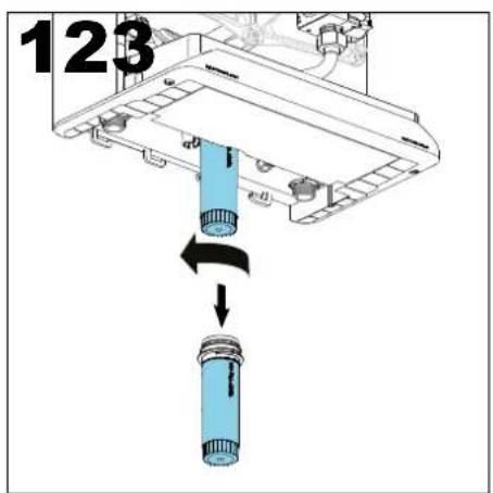


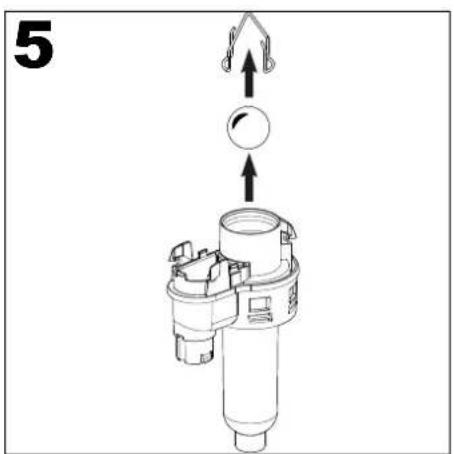


10.1.5 Service B
▶ Replace the flue pipe's O-ring (620314).
▶ Replace syphon cup's O-ring (875664).
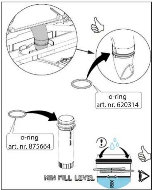
10.1.6 Service C
▶ Loosen the upper nut of the gas valve and remove the gas restrictor disc.
▶ Replace the O-ring on the gas restrictor disc and then reinstall it.
Then tighten by hand the upper nut of the gas valve again.
▶ Remove the fan from the front plate (2 nuts M4) and remove the gasket.
Remove the flue gas valve from the inlet opening of the front plate and check whether it still works properly. To do this, check that the silicone "flap" is not cracked or otherwise damaged.
Then place it back in the front plate. Make sure that the flue gas valve is put back in the correct position.
Remove the circlip from the gas mixing tube/fan connection and pull the gas mixing tube out of the gas-air module of the fan.
▶ Clean the inside of the fan tunnel and the gas-air module and slide it back into the tunnel.
▶ Replace the O-ring on the gas mixing tube and put it back in the fan. Reinstall the circlip.
Place a new fan seal and reassemble the fan to the front plate.
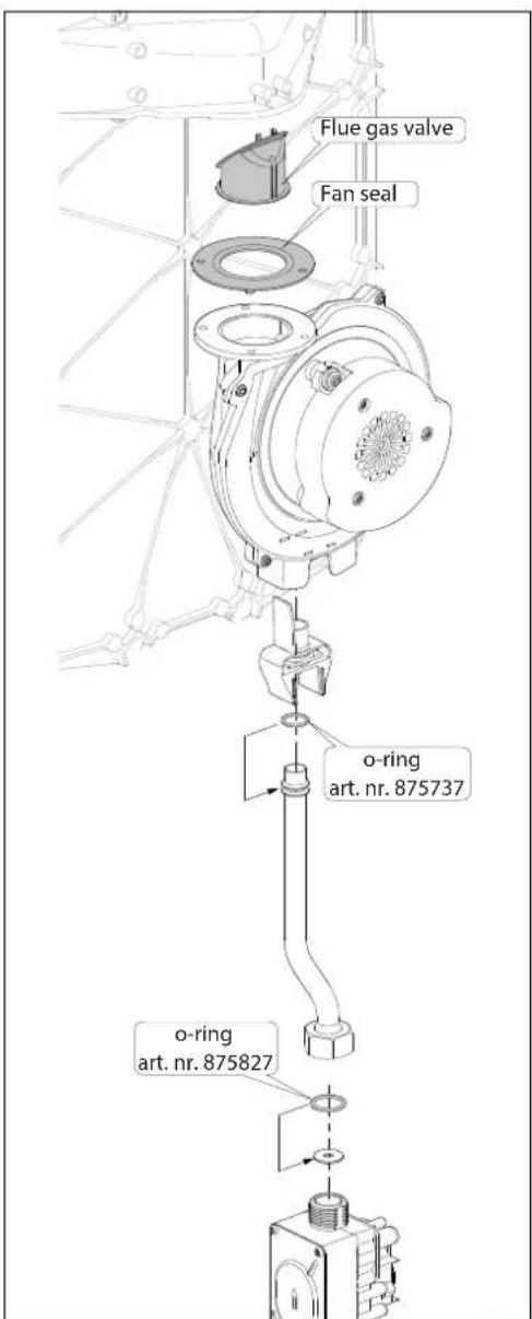
10.1.7 Assembly
▶ Check the position of the ignition pin using the control tool (art.no.074617).
▶ Replace the Viton front plate seal. Ensure the seal is pushed fully into the O-ring chamber around the whole front plate.
Note: avoid stretching during assembly. Make sure that the seal remains in place when placing the front plate.
▶ Replace the seal between the gas supply tube and gas valve. Ensure the seal is pushed fully into the O-ring chamber.


IMPORTANT
▶ Incorrect positioning of the front plate seal ring can lead to damage to the ring, condensation and flue gas leakage.
▶ Check whether there is a thin layer of ceramic grease both sides of the front plate where the shoulder bolts protrude especially between the flange of the shoulder bolts and the front plate itself.
If there is insufficient grease present, extra must be applied using the foam application tool (A) within the kit (ceramic grease kit available to order, part number 090587).
Place the front panel back on the heat exchanger and attach it with the 6mm Allen key shoulder bolts. Tighten the shoulder bolts (torque ± 11 Nm)* by hand, working diagonally. The order of tightening is shown in the diagram. Check the seal in the front plate again.
▶ Fit the gas supply tube to the gas valve, place it in the correct position and tighten it sufficiently. Then tighten the upper connection.
▶ Tighten the burner bolts diagonally by hand.
▶ Reinstate the electrical connector to the gas valve and fan.
* Do not overtighten
Clicking noise (expansion) during operation is normally due to overtightening of the front panel bolts or lack of ceramic grease.
Please check sufficient ceramic grease has been applied and the correct torque setting applied before calling the Intergas service team.

10.1.8 Commissioning and end control
▶ Open the gas isolation valve and check both of the gas unions for tightness.
▶ Check and repair any water leaks within the appliance.
▶ Check the static gas inlet pressure.
▶ Commission the appliance.
▶ Switch the appliance to maximum output. To do this, hold the Service symbol and at the same time tap the Plus symbol twice + until the capital letter H appears on the right display. Check the dynamic gas inlet pressure.
▶ Check the Due at maximum en minimal output as described in §8.4.
▶ Check the flue integrity of the heat exchanger and the flue connections of the syphon and the flue gas pipe. Use a cooled mirror for this, for example.
▶ Check the front plate, the connection of the fan on the front plate and the flue gas parts for leakage.
Tap the Minus symbol — and the Plus symbol + at the same time to terminate the program, replace the room sealed cover back in its position, Hand tighten screws under the appliance using a 5 mm allen key (do not over tighten).
▶ Check the tightness and locking of the siphon.


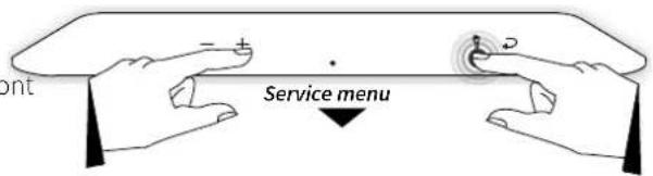

Testprogramma "H"
▶ In case of concentric flue gas systems.
- Switch the appliance to maximum output again (service program H). Check that the air supplied for combustion does not contain flue gases (recirculation from the collective duct). To do this, remove the silicone sealing cap on the side of the adapter. Place a silicone hose or similar in this that sufficiently seals the hole. Then place the measuring probe in this hose. Measured values must be equal to outdoor air values (BRL 6000-25). After a successful measurement, remove the hose and place the silicone sealing cap back into the adapter.
▶ Check the domestic hot water facility for correct operation.
11 TECHNICAL SPECIFICATIONS
| Appliance category C13; C33; C53 | |
| Gas inlet pressure G20: 20 mbar, G31: 37 mbar | |
| Suitable for gas II | 2E3P |
| Technical data | Intergas Superflow | |
| Type 45 Type 60 | ||
| Domestic hot water | |||
| Nom. load upper value | kW | 6.8 - 47.2 | 8.3 - 58.3 |
| Nom. load lower value | kW | 6.1 - 42.5 | 7.5 - 52.6 |
| Nom. output kW 41.9 52.3 | |||
| Tap threshold | l/min | 1.5 | |
| Domestic hot water flow 40°C | l/min | 20 | 25 |
| Domestic hot water flow 60°C | l/min | 12 | 15 |
| Domestic hot water temperature (standard setting) | °C | 60 | 60 |
| Domestic hot water temperature range | °C | 40 - 65 | |
| Other data | |||
| Gas consumption (G20) m | 3/h | 0.65 - 4.50 0.79 - 5.57 | |
| Gas consumption (G31) m | 3/h | 0.25 - 1.74 0.31 - 2.15 | |
| Average flue temperature °C | 75 | ||
| Flue gas mass flow (minimum-maximum) kg/h | 10.0 - 70.3 12.4 - 87.1 | ||
| Maximum counter-pressure Pa | 250 | ||
| Electric data | |||
| Mains voltage V | 230 | ||
| Safety class IP | IPX4D | ||
| Recorded output: full load W | 115 120 | ||
| Recorded output: standby W | 2 | 2 | |
| Overall dimensions and weight | |||
| Height mm 755 755 | |||
| Width | mm | 400 450 | |
| Depth | mm | 260 277 | |
| Weight | kg | 27.5 | 30 |
11.1 Electrical schematic

| 230V~ component | |||
| Connector | Connections Designation Description | ||
| X1 | 1-2-3-4-5-6 |  | Fan |
| X5 1-2 | [54W0] | Power mains cord (stripped) 230V~ 50Hz(1=L (brown), 2=N (blue), ± = ground (green/yellow)) | |
| X8 1-2 | -3-4-5 |  | Ignition unit |
| 24V = component | |||
| Connector | Connections Designation Description | ||
| X9 | 1-2-3-4-5-6-7-8 |  | Electronic bypass valve |
| X14 |  | PC Interface | |
| X15 | 1-2 |  | Gas valve |
| 3-4-5-6 |  | BMM (Appliance Memory Module) | |
| 7-11 |  | Flue gas sensor (S5) | |
| 7-10-13 |  | Heat exchanger sensor (S0) | |
| 7-12 |  | Cold water sensor (S4) | |
| 7-16 |  | Domestic hot water sensor (S3) | |
| 7-9-17 |  | Flow sensor | |
11.2 Product card according to CELEX-32013R0811, Appendix IV
| Supplier | Intergas Verwarming BVEuropark Allee 27742 NA Coevorden, The Netherlands | |||
| Type designation Symbol Unit | Superflow | |||
| 45 60 | ||||
| Sound power level L | WA | dB 62 | 60 | |
| Declared load profile DHW | - | - | XXL | XXL |
| Energy efficiency class for water heating | - | - | A | A |
| Domestic hot water efficiency η | WH | % | 85 | 86 |
| Annual electricity use | AEC | kWh | 18 | 13 |
| Annual fuel use | AFC | GJ | 23 | 22 |

IMPORTANT
Before installation, read the installation manual and the operation instructions.
This appliance is not intended for use by individuals (including children) with reduced physical, sensory or mental capacities, or lack of experience and knowledge, unless supervision of or instruction about the use of the appliance is given by a person who is responsible for their safety.
The appliance and system must be inspected periodically by an authorised installer and cleaned if necessary. See §10.
The appliance can be cleaned with a damp cloth. Do not use aggressive or scrubbing cleaning agents or solvents.
11.3 NTC resistances
| NTC 12 kOhm | |||||||
| T [°C] | R [Ω] | T [°C] | R [Ω] | T [°C] | R [Ω] | T [°C] | R [Ω] |
| -15 76020 15 1 | 8300 45 5522 75 1994 | ||||||
| -10 58880 20 1 | 4770 50 4609 80 1717 | ||||||
| -5 45950 25 12 | 000 55 3863 85 1467 | ||||||
| 0 36130 30 9805 | 60 3253 90 1266 | ||||||
| 5 28600 35 8055 | 65 2752 95 1096 | ||||||
| 10 22800 40 6653 | 70 2337 100 952 | ||||||
12 GUARANTEE PROVISIONS AND CE DECLARATION
- The installer must be registered with Gas Safe, installer must complete the Benchmark Commissioning Checklist in full at the time the boiler is installed. The Benchmark must be made available and can be found at the back of the installation instructions. The Benchmark Commissioning Checklist must be retained on site by the owner/occupier for inspection during an engineer's visit.
- The boiler and Intergas system filter* must both be registered for warranty with Intergas by either the installer or you the householder, within 30 days of the boiler being installed. For the new build properties, this must be done within 30 days of the sale being completed. if these conditions are not met, the warranty will not be valid. (*Intergas system filter must be installed on the same date as the boiler and registered for warranty at the same time).
The product must be registered via the internet at www.intergasheating.co.uk or on the Intergas MiREG website www.myintergasregistration.co.uk or by returning the warranty card.
- The boiler must be serviced annually by a registered Gas Safe Engineer in accordance with manufacturer's instructions.
- Service details must be recorded in the Benchmark Checklist or provide proof of service which must be available for inspection.
- The cost of the annual service is not included in the warranty.
If the above conditions are not meet this warranty will be limited to 12 months from the date of installation or date of Manufacture, as recorded on the Benchmark commissioning checklist.
- Only boiler component failures are covered by the warranty. The warranty does not cover any connected system or accessories such as time switches, thermostats, motorised valves, external pumps and so on.
- Any repair carried out under the terms of this warranty does not extend the warranty beyond its original period.
- If the boiler breaks down, Intergas may ask you* (Homeowner or Installer) to pay a deposit before we visit to complete the repair. We will return the deposit in full if we find a fault that is covered by the warranty. We may keep the deposit if we cannot access the property at the time we have arranged with you to visit or we find other conditions of this warranty have not been met.
- The system must be flushed and cleansed in accordance with BS7593:2019.
- If any failure is caused by contaminated water in the system the engineer visit becomes chargeable.
- All installation, non boiler or external system faults calls will be charged to the home owner/occupier.
- Roof space installation BS6798:2014 Require a permanently fixed access ladder must service installations in lofts or attics. Adequate lighting and permanently fixed flooring must also be available.
- Engineers will not carry out repairs if they think accessing the boiler would be a risk to Health and Safety. A responsible adult must be at the property to give our engineer access to the boiler.
- If your boiler is in a cupboard, there must be enough room for the engineer to work (the minimum area as set out in the installation instructions). We are not responsible for removing cupboards, kitchen units, trims etc to gain access for repairs.
- In hard water areas of 200ppm or above, appropriate
protection actions must be taken in accordance with BS 7593:2019 in line with building regulations Part L1. (Above 200ppm we recommend Combimate*, Adey Electroscale or Hydroflow HS38 should be installed. 300ppm and above we recommend a Combimate*, Water softener* or HS38 should be installed.) (*serviceable item)
- The central heating system must be maintained in accordance with the Benchmark Guidance on water Treatment in Central Heating Systems & BS7593:2019, we recommend the use of Fernox, Sentinel or Adey products, Inhibitors & filters. It is important that the correct concentration of water treatment is maintained for the life of the boiler, should we attend a warranty call Intergas reserve the right to take system water samples and should they fail the aforementioned requirements then the warranty will be void and the call will become chargeable. (Intergas system filter must be installed & registered at the same time as the boiler for enhanced warranty period).
- If the boiler suffers a breakdown you should contact Intergas on 01527 888000 selecting option 2. Our normal working hours, excluding Bank Holidays are: 8.00am – 5.00pm Monday to Friday and 8.00am – 12.00pm Saturday mornings.

CE DECLARATION
Manufacturer Intergas Heating Limited Address Unit 2
| Easter | Park |
| Worcester | Road |
| Kidderminster | |
| DY11 | 7AR |
hereby declares that CH appliance: INTERGAS, Type:
▶ Superflow 45
▶ Superflow 60
Meets the provisions of the following directives:
▶ Low Voltage Directive (2014/35/EC)
▶ Gas Appliance Regulation (2016/426/EC)
▶ Directive regarding efficiency requirements for new oil and gas-burning central heating boilers (92/42/EC)
▶ EMC Directive (2014/30/EC)
▶ RED Directive (2014/53/EC)*
▶ Ecodesign (2009/125/EG)
▶ Energy labelling (2010/30/EU)
* The conformity declaration can be requested from Intergas.
CE
gary wdd
G. Rudd February 2024
Intergas Heating Ltd
Intergas Heating Limited Unit 2
Easter Park
Worcester Road
Kidderminster
DY11 7AR
Tel: 01527 888000
Fax: 01384 279480
info@intergasheating.co.uk
www.intergasheating.co.uk
2024 Intergas Heating Ltd.

All rights reserved.
The information provided applies to the standard version of the product. Intergas Heating Ltd can therefore not be held liable for any damage ensuing from specifications that deviate from the standard version of the product. Although the available information has been composed with all possible care, Intergas Heating Ltd cannot be held liable for any errors in the information or for the consequences of such.
Intergas Heating Ltd cannot be held liable for damage ensuing from activities that are performed by third parties.
This document is subject to modifications without prior notice.

84150401
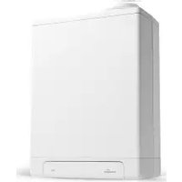

- INSTALLATION MANUAL
- CONTENTS
- 2 SAFETY REGULATIONS 6
- 3 GENERAL APPLIANCE INFORMATION 7
- 4 MAIN COMPONENTS 10
- 5 INSTALLATION 14
- 6 CONNECTION 18
- 7 OPERATION 34
- 8 SETTINGS AND ADJUSTMENTS 36
- 9 FAULTS 48
- 10 MAINTENANCE 53
- 11 TECHNICAL SPECIFICATIONS 60
- 12 GUARANTEE PROVISIONS AND CE DECLARATION 64
- 1 PREFACE
- 1.1 REGULATION
- 1.2 WARNINGS
- 1.3 MANUAL HANDLING
- 1.4 PICTOGRAMS
- CAREFUL / IMPORTANT
- COMMENT
- SEE
- 1.5 WARNINGS ON THE BOX
- INSTRUCTION (THIS SIDE UP)
- INSTRUCTION (FRAGILE)
- INSTRUCTIE (STACK)
- 1.6 ABBREVIATIONS
- SAFETY PRECAUTIONS IF YOU SMELL GAS
- A GAS LEAK COULD POTENTIALLY CAUSE AN EXPLOSION. IF YOU SMELL GAS, OBSERVE THE FOLLOWING RULES
- 2.1 GENERAL
- 2.2 THE INSTALLATION
- 3.1 GENERAL
- 3.1.1 UKCA LABEL
- 3.1.2 GAS CATEGORY
- 3.2 OPERATION
- CAREFUL
- 3.3 DATA PLATE
- IDENTIFICATION OF THE PRODUCT
- 3.4 CONTROL PANEL
- 3.5 OPERATIONAL MODES
- THE APPLIANCE IS SWITCHED OFF
- THE APPLIANCE IS SWITCHED ON
- THE APPLIANCE IS IN OPERATION
- 4.1 STANDARD SCOPE OF DELIVERY
- 4.2 ACCESSORIES
- INSTALLER IMPORTANT POINTS
- PLEASE READ ALL INSTRUCTIONS BEFORE FITTING THIS APPLIANCE
- 5.1 OVERALL DIMENSIONS
- 5.2 INSTALLATION LOCATION
- 5.2.2 REMOVING/INSTALLING THE FRONT PANEL
- REPLACING THE ROOM SEALED FRONT COVER
- 5.3 INSTALLING THE APPLIANCE
- 6.1 DOMESTIC HOT WATER CONNECTION
- 6.1.1 DOMESTIC HOT WATER CIRCUIT RESISTANCE GRAPH
- 6.2 ELECTRICAL CONNECTION
- TO GAIN ACCESS TO THE ELECTRICAL CONNECTIONS OR PCB
- 6.3 GAS CONNECTION
- 6.4 CASCADE FUNCTION
- TANKLESS WATER HEATER CASCADE SYSTEM
- LOW VOLTAGE WIRING
- LINE VOLTAGE WIRING
- CASCADE CONFIGURATION
- CASCADE COMMUNICATION
- CASCADE ADJUSTMENTS
- WATER SIDE
- 6.5 FLUE AND AIR SUPPLY DUCT
- 6.5.1 DRAFT, MATERIALS AND INSULATION
- 6.6 PIPELINE LENGTHS
- 6.6.1 REPLACEMENT LENGTHS
- 6.6.2 EXAMPLE CALCULATION
- COMMENTS
- TWIN FLUE GENERAL ASSEMBLY GUIDE
- FLUE GAS SECTION ASSEMBLY
- AIR SUPPLY SECTION ASSEMBLY
- 6.7 GENERAL LAYOUT OF THE FLUE
- 6.7.1 WALL TERMINAL WITH TWIN-PIPE HORIZONTAL TERMINAL C13
- ALLOWED PIPELINE LENGTH
- TWIN-PIPE
- CONCENTRIC
- ASSEMBLY OF COMBI-PIPE HORIZONTAL TERMINAL
- 6.7.2 FLUE TERMINAL POSITIONS 60/100MM
- CONCENTRIC FLUE 60/100
- NOTE
- CAUTION
- TO REDUCE THE TELESCOPIC FLUE LENGTH FURTHER
- 6.7.3 PMK TERMINAL POSITIONS 60MM
- 6.7.4 ROOF TERMINAL WITH COMBI-PIPE VERTICAL TERMINAL C33
- IMPORTANT
- PERMISSIBLE EQUIVALENT PIPELINE LENGTH
- ASSEMBLY OF TWIN-PIPE VERTICAL TERMINAL
- 6.7.5 ROOF TERMINAL AND AIR SUPPLY DUCT FROM THE FAÇADE C53
- ASSEMBLY OF HORIZONTAL AIR SUPPLY DUCT
- ASSEMBLY OF VERTICAL FLUE TERMINAL
- 6.7.6 CLAMPING THE FLUE SYSTEM (TWIN AND CONCENTRIC)
- 6.7.7 TWIN FLUE TERMINAL POSITIONS
- 7.1 USING THE CONTROL PANEL
- 7.2APPLIANCEPREPARATION
- 7.2.1 DOMESTIC HOT WATER FACILITY
- 7.2.3 GAS SUPPLY
- 7.3 COMMISSIONING PROCEDURE
- 7.4 SHUTTING DOWN THE APPLIANCE
- 8.1 NAVIGATE THE SETTINGS
- 8.1.1 MAIN MENU
- 8.1.2 DOMESTIC HOT WATER MENU
- TO ADJUST THE DOMESTIC HOT WATER TEMPERATURE SETTING
- ON
- ECO
- OFF
- TO ADJUST THE DHW COMFORT FUNCTION
- 8.1.3 SERVICE MENU
- TEST PROGRAMS
- TO ACTIVATE THE 'L' TEST PROGRAM
- TO ACTIVATE THE 'H' TEST PROGRAM
- 8.1.4 PARAMETERS
- (INSTALLER'S) PARAMETERS
- TO MODIFY A PARAMETER
- (FOR EXAMPLE, MODIFY PARAMETER 74 FROM 7 TO 3)
- 8.1.5INFOMENU
- LEFT DISPLAY RIGHT DISPLAY
- 8.1.6 CASCADE MENU
- TO ACCESS THE CASCADE PARAMETERS
- 8.2 CONVERSION TO ANOTHER GAS TYPE
- CHANGING / REPLACING THE GAS RESTRICTION RING
- 8.4 INSPECTION OF GAS AIR CONTROL
- 8.4.1 MEASURING FLUE GAS AT HIGH FIRE
- 8.4.2 MEASURING FLUE GAS AT LOW FIRE
- EXAMPLE (NATURAL GAS G20)
- 8.4.3 MINIMUM OUTPUT CORRECTION
- 9.1 FAULT CODES
- VIEWING FAULT CODES
- RESETTING THE APPLIANCE
- 9.2 OTHER FAULTS
- 9.2.1 NO DOMESTIC HOT WATER (DHW)
- 9.2.2 DOMESTIC HOT WATER DOES NOT REACH THE CORRECT TEMPERATURE
- 9.2.3 BURNER IGNITES LOUDLY
- 9.2.4 BURNER RESONATES
- 9.3 NOTIFICATIONS
- 9.4 DEVIATING FROM HOUSEHOLD USE
- TO RESET THE GAS CONSUMPTION MEASUREMENT
- BELANGRIJK
- 10.1 ANNUAL SERVICE A
- 10.1.1 APPLIANCE CHECK-UP
- 10.1.2 PREPARATIONS
- 10.1.3 CLEANING
- VOORZICHTIG
- 10.1.4 SYPHON MAINTENANCE
- 10.1.5 SERVICE B
- 10.1.6 SERVICE C
- 10.1.7 ASSEMBLY
- DO NOT OVERTIGHTEN
- 10.1.8 COMMISSIONING AND END CONTROL
- 11.2 PRODUCT CARD ACCORDING TO CELEX-32013R0811, APPENDIX IV
- 11.3 NTC RESISTANCES
- 12 GUARANTEE PROVISIONS AND CE DECLARATION
- THE PRODUCT MUST BE REGISTERED VIA THE INTERNET AT WWW.INTERGASHEATING.CO.UK OR ON THE INTERGAS MIREG WEBSITE WWW.MYINTERGASREGISTRATION.CO.UK OR BY RETURNING THE WARRANTY CARD
- IF THE ABOVE CONDITIONS ARE NOT MEET THIS WARRANTY WILL BE LIMITED TO 12 MONTHS FROM THE DATE OF INSTALLATION OR DATE OF MANUFACTURE, AS RECORDED ON THE BENCHMARK COMMISSIONING CHECKLIST
- CE DECLARATION
- INTERGAS HEATING LTD
Brand : Intergas
Model : Superflow 45
Category : Boiler