Xtend Split - Water pump Intergas - Free user manual and instructions
Find the device manual for free Xtend Split Intergas in PDF.


| Product Type | Water Pump |
| Brand | Intergas |
| Model | Xtend Split |
| Application | Circulation for heating systems |
| Power Supply | 230V / 50Hz |
| Power Consumption | 60 W |
| Maximum Flow Rate | 2.5 m³/h |
| Maximum Head | 6 m |
| Dimensions (H x W x D) | 180 x 150 x 130 mm |
| Weight | 2.3 kg |
| Material | Stainless steel and cast iron |
| Protection Rating | IP44 |
| Insulation Class | F |
| Noise Level | < 35 dB(A) |
| Operating Temperature Range | -10 °C to +60 °C |
| Maximum Liquid Temperature | 110 °C |
| Connection Size | 1" (BSP) |
| Control Type | Manual speed selection |
| Maintenance | Sealed bearing, no maintenance required |
| Safety Features | Thermal overload protection |
| Warranty | 2 years |
Frequently Asked Questions - Xtend Split Intergas
User questions about Xtend Split Intergas
0 question about this device. Answer the ones you know or ask your own.
Ask a new question about this device
Download the instructions for your Water pump in PDF format for free! Find your manual Xtend Split - Intergas and take your electronic device back in hand. On this page are published all the documents necessary for the use of your device. Xtend Split by Intergas.
USER MANUAL Xtend Split Intergas
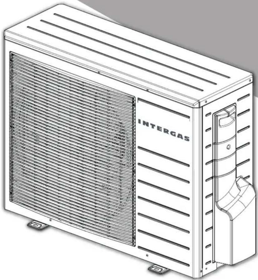
INSTALLATION INSTRUCTIONS
Hybrid air-water heat pump system
Please read these installation instructions carefully before installing and using the system. Keep these installation instructions in a safe place. Always act in accordance with the indicated instructions.
CONTENTS
1 Explanatory notes and safety instructions 6
1.1 General explanation....6
1.1.1 Icons within the installation instructions....6
1.1.2 Symbols on the rating plate....6
1.1.3 Symbols on the packaging....7
1.1.4 Abbreviations....7
1.1.5 Information about the text 7
1.2 General safety instructions....8
1.3 Points of attention for installation....9
1.4 Points of attention for maintenance.... 10
1.5 Regulations, standards and safety requirements 11
2 Scope of delivery 12
3 Required components and accessories 13
3.1 Required components.... 13
3.2 Accessories....14
4 General 15
4.1 General principle.... 16
4.2 Energy label Xtend hybrid heat pump system 16
5 Specifications 17
5.1 Indoor unit 17
5.2 Outdoor unit 17
5.3 Common specifications 17
5.3.1 Heating mode: L7/W35 measured in accordance with EN 14511-2 18
5.3.2 Heating mode: L2/W35 measured in accordance with EN 14511-2 18
5.3.3 Heating mode: L7/W45 measured in accordance with EN 14511-2 18
5.3.4 Technical parameters in accordance with EN 14825....18
6 Indoor unit 20
6.1 Function....20
6.2 Operation 20
6.3 Rating plate indoor unit 21
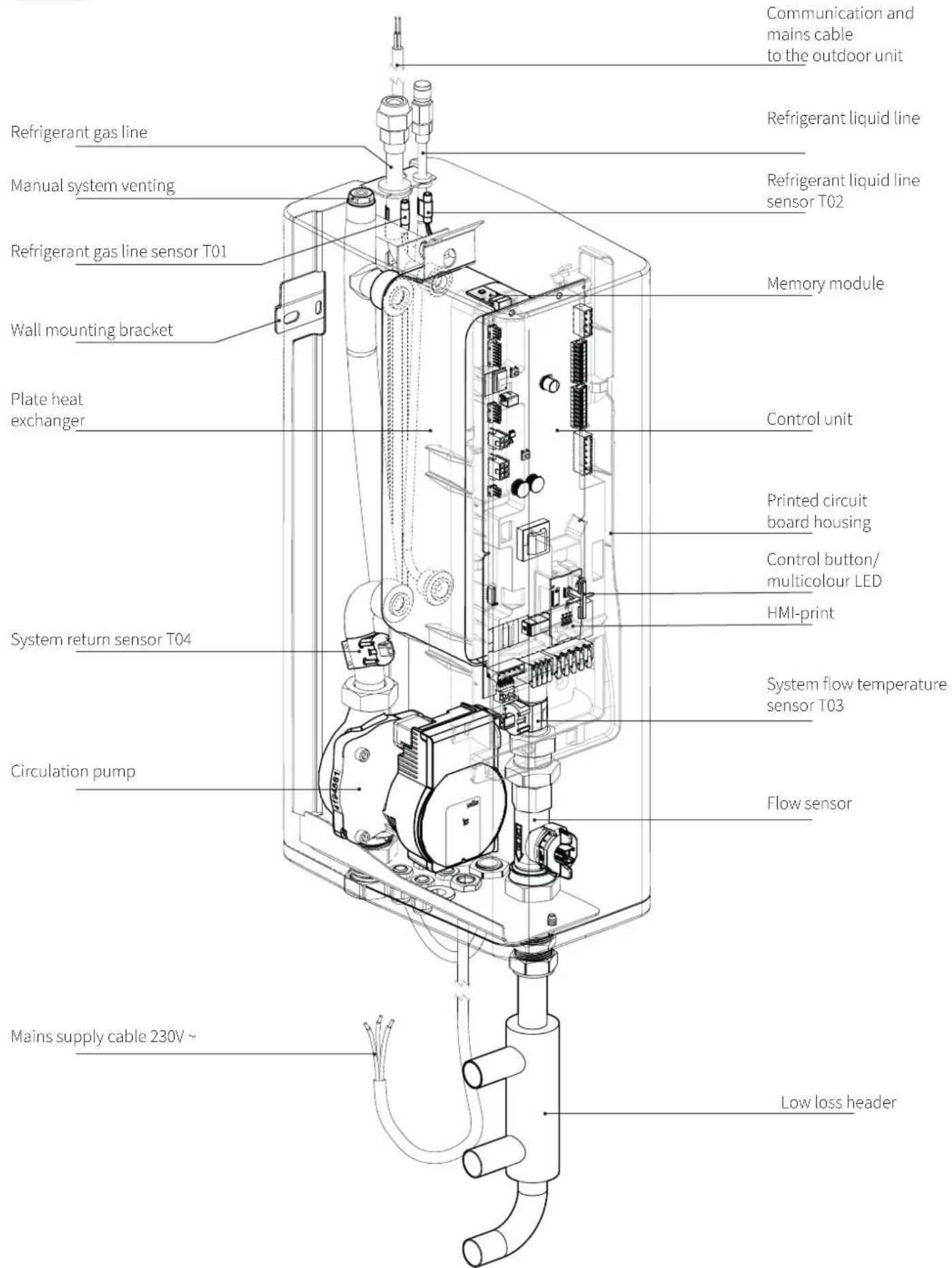
6.4 Main components indoor unit 22
6.5 Dimensions and connections of the indoor unit 23
7 Outdoor unit 24
7.1 Function....24
7.2 Main components outdoor unit 24
7.3 Dimensions and connections outdoor unit 25
7.4 Rating plate outdoor unit 25
8 System installation 26
8.1 Installation overview 26
8.2 Distance between the indoor and outdoor units 28
8.3 Installing the indoor unit 29
8.3.1 Installation location....29
8.3.2 Mounting the indoor unit 29
8.3.3 Removing and replacing the front cover 30
8.4 Water-side connection 31
8.4.1 Connecting the indoor unit and the boiler using the low loss header 32
8.5 Setting up the outdoor unit 33
8.5.1 Points of attention for location.... 33
8.5.2 Transport....33
8.5.3 Installing the outdoor unit 34
8.6 Refrigerant connections 35
8.6.1 Points of attention for refrigerant lines.... 35
8.6.2 Making refrigerant connections to the indoor unit 36
8.6.3 Making refrigerant connections to the outdoor unit 37
8.6.4 Strength test and Tightness testing.... 37
8.6.5 Creating a vacuum in the refrigerant lines....38
8.6.6 Refrigerant actions....38
8.6.7 Insulating the refrigerant lines 39
8.6.8 Emptying the meter set....39
8.6.9 Checking the refrigerant actions....40
8.7 Making electrical connections....40
8.7.1 Points of attention for electrical installation....40
8.7.2 Electrical installation overview 41
8.7.3 Electrical schematic (indoor unit) 42
8.7.4 Electrical diagram outdoor unit 44
8.8 Routing and connecting cables 45
8.8.1 Wiring the outdoor unit to the indoor unit 45
8.8.2 Connector plug information 46
8.8.3 Wiring the boiler to the indoor unit 47
8.8.4 Wiring the indoor unit to an existing boiler 47
8.8.5 Connecting the room thermostat to the indoor unit 48
8.8.6 Wiring the outdoor sensor to the indoor unit (optional) 49
8.8.7 Wiring a T43 NTC temperature sensor to the indoor unit (optional) 49
8.8.8 Installing and using the Comfort Touch room thermostat 50
8.8.9 Comfort Touch app 50
8.8.10 Connecting a secondary pump....51
9 Commissioning the system 52
9.1 Preparatory work 52
9.2 Filling, cleaning and venting the central heating system 52
9.2.1 Cleaning and flushing the central heating system 52
9.2.2 Filling and venting the central heating system....52
9.2.3 Checking the heating circuit 53
9.3 Configuration procedure 54
10 Operation and readout 55
10.1 Multicolour LED description 55
10.2 Connectivity procedure WiFi control screen....55
10.2.1 Quick guide (quick connection via QR-codes) 55
10.2.2 Manual connection 56
10.3 Wi-Fi control screen description....57
10.3.1 Overview (main page) 57
10.3.2 Connections 57
10.3.3 Settings (for the end user as well as the installer) 57
10.3.4 Service (specifically for installer) 57
11 Settings and adjustments 58
11.1 Settings (Wi-Fi control screen) 58
11.1.1 Discription day programs....58
11.1.2 Time settings 60
11.1.3 Hybrid mode....60
11.2 Service menu (specifically for the installer)....61
11.2.1 Access to the service menu 61
11.2.2 Installation wizard 61
11.2.3 Tools....61
11.2.4 Parameters (adjustment) 62
11.2.5 Statistics 62
11.2.6 Firmware (update) 62
11.3 Adjusting the hybrid work mode 63
11.3.1 Setting the hybrid mode....63
11.4 Settings for activating the boiler....64
11.4.1 Setting a reduced temperature....64
11.5 Room heating settings (CH mode) 65
11.6 Parameter list.... 66
12 Faults/Notifications 72
12.1 Fault codes 72
12.2 Notification codes....73
12.3 Other malfunctions....74
12.3.1 Malfunction within the indoor unit 74
12.3.2 CH does not get up to temperature....74
12.3.3 CH installation stays too hot 74
12.3.4 Malfunction of the outdoor unit 75
13
Maintenance
76
13.1 Cleaning the filter 76
13.2 Indoor unit maintenance work....76
13.3 Outdoor unit maintenance work 77
13.4 Decommissioning the system 78
13.4.1 Removing and recycling 78
13.4.2 Collecting refrigerant 78
13.4.3 Label 78
14 Product Fiche (Commission Delegated Regulation (EU) 811/2013) 79
15 Spares short list (Indoor unit) 80
16 Spares short list (Outdoor unit) 81
17 Warranty provisions 82
18 Hybrid system commissioning checklist and warranty validation record 83
19 Service & interim heat pump work record 84
1 EXPLANATORY NOTES AND SAFETY INSTRUCTIONS
Intergas Heating Ltd accepts no liability whatsoever for damage or injury caused by failure to (strictly) observe the safety regulations and instructions, or by negligence during the installation of the Intergas appliance and any accessories.
This appliance should only be operated by persons who are competent to do so and have read and fully understand the the user instructions.
Cleaning of the indoor unit casing can be achieved using a damp cloth only and no solvent based products.
Cleaning of the outdoor unit must only be undertaken by an F-Gas / REFCOM registered and Intergas trained engineer.
Maintenance of both indoor and outdoor units must only be performed by an F-Gas / REFCOM registered and Intergas trained engineer.
Intergas Heating Ltd is constantly looking for ways to guarantee the quality of its products and to improve them where necessary. As a result, it reserves the right to modify the features mentioned within this document at any time.
Read and observe all safety instructions within this manual to prevent unsafe situations, fire, explosion, property damage or personal injury. When in doubt or if you have questions, contact Intergas Heating Ltd.
1.1 General explanation
1.1.1 Icons within the installation instructions

CAUTION / IMPORTANT
Procedures which, if not carried out with care, may damage the product, its surroundings or the environment, or may result in personal injury.

NOTE
Procedures and/or instructions which, if not followed, could negatively affect the operation of the system.

WARNING
Dangerous voltage or electric shock hazard
1.1.2 Symbols on the rating plate

INSTRUCTIONS
Read the included manual.

INSTRUCTIONS
See the operating instructions.

INSTRUCTIONS
Read the technical manual.

CE DECLARATION
Legal requirements for consumer products marketed within the EU relating to safety, health and the environment.

FLAMMABLE REFRIGERANT
The device contains flammable refrigerant.

RECYCLING
Take discarded products to a designated collection and recycling location.
1.1.3 Symbols on the packaging

INSTRUCTIONS (THIS SIDE UP)
The arrow is pointing up to indicate that the contents must be transported and stored upright.

INSTRUCTIONS (FRAGILE)
This symbol indicates that the contents of the box are fragile. Handle the contents carefully.

INSTRUCTIONS (KEEP DRY)
This symbol indicates that the contents of the box must be kept dry.

INSTRUCTIONS (MAXIMUM STACKING HEIGHT)
This symbol indicates how many of these boxes can be stacked.

INSTRUCTIONS (NO STANDING)
This symbol indicates that you cannot stand on the contents of the box.

INSTRUCTIONS (DO NOT USE HOOKS)
This symbol indicates that a hook cannot be used to hoist the product.

INSTRUCTIONS (NO TILTING)
This symbol indicates that the contents of the box cannot be tilted.

INSTRUCTIONS (DO NOT STACK ON SIDE)
This symbol indicates that the product cannot be stacked on its side.

REFRIGERANT TYPE (R32)
R32 is an A2L refrigerant, which has low flammability and low toxicity.
1.1.4 Abbreviations
▶ CH: Central heating
▶ DHW: Domestic hot water
IDU: Indoor unit
▶ ODU: Outdoor unit
▶ WDC: Weather-dependent control
1.1.5 Information about the text
The dimensions within the installation instructions are in millimetres unless otherwise specified.
1.2 General safety instructions

IMPORTANT
▶ Read the installation and operating instructions before installation.
Installing the system incorrectly can result in serious or life-threatening injuries.
▶ A qualified installer must install the Intergas hybrid heat pump system, as incorrect installation can lead to leakage, electric shock or fire.
▶ Ensure that the system and the electrical connections are connected and earthed correctly to prevent parts and housing from becoming live. Electrical work may only be carried out by a qualified electrician; see §8.2.
Do not insert fingers or objects into the outdoor unit's fan or the ribs of its evaporator. This can lead to serious injuries.
To prevent short circuiting or fire, shut down the system immediately if it is not functioning correctly or if 'unusual' air is detected.
If parts of the heat pump system need to be replaced or removed, this must be carried out by a qualified engineer.**
▶ Repairs and restoration work may only be carried out by a qualified or Intergas engineer. Improper repair or restoration work may result in water damage, short circuiting, personal injury or fire.
This product contains fluorinated greenhouse gases. Do not allow these gases to escape into the atmosphere.
The refrigerant (R32) is flammable. If this refrigerant comes into contact with a heat source, it can lead to fire or the formation of hazardous gas.
**
City and Guilds
1 Giltspur Street
London EC1A 9DD
Telephone 0844 543 0033
Building Engineering Services Association (BESA)
Lincoln House
137-143 Hammersmith Road
London
W14 0QL
Telephone 020 7313 4900
LCL Awards
Unit 1 Belvue Business Park
Belvue Road
Northolt
Middlesex
UB5 5QQ
Telephone 020 8839 2439

IMPORTANT
During the installation, the main Regulations that apply:
• Health and Safety at Work Act (HSWA)
• Workplace (Health, Safety and Welfare) Regulations
- Manual Handling Operations Regulations
• Regulatory Reform (Fire Safety) Order
• Electricity At Work Regulations
• Control of Substances Hazardous to Health (COSHH) Regulations
The system must not be positioned near flammable substances. This can lead to a fire hazard.
The indoor unit must always be positioned upright.
▶ Ensure that the wall on which the indoor unit is mounted is strong enough to support the system. Additional reinforcement is required if the system is installed on plasterboard stud walls.
The CH system must be filled and ventilated.
The water pressure in the CH system must be at least 1.0 to 1.5 bar when cold. Do not use the CH system if it is not full and vented.
▶ Ensure that the outdoor unit is placed on a foundation that is stable and level enough to prevent it from tipping over. Ensure that condensed water can be drained.
▶ Check whether the correct circuit breaker (B16) has been fitted to the electrical consumer unit. If the circuit breaker is too high, unsuitable or missing it can lead to short-circuiting or fire.
▶ Check whether the electrical supply circuit(s) to which the installation will be connected is/are suitable for the required capacity.
▶ Ensure that a three-pole isolator switch (see §8.7.3 and §8.8.1) is placed near the outdoor unit, it must be IPX rated and designed to carry the required electrical loading.
The extra fittings specified within these installation instructions (filter, non-return valve and wiring etc.) must be supplied and fitted by the installer. Damages and consequences resulting from not applying the specified fittings are not covered by the Intergas warranty and will be the responsibility of the installer/user.
Before installing any type of low temperature heating system it is essential a full room by room heat loss calculation is completed of the property, this should be fully explained to the home owner, especially regarding the different operational aspects, temperature of the emitters, duration of operation, electricity usage etc. It is recommended that the level of thermal insulation for the property walls, floor and roof are increased (where possible) to the maximum to help lower the U-values (The lower the U-value, the slower the heat escapes from the property).
1.4 Points of attention for maintenance

IMPORTANT
The indoor unit and outdoor unit can be cleaned with a damp cloth. Do not use aggressive or abrasive cleaning agents or solvents.
During maintenance, check that the base/foundation of the outdoor unit is strong and stable. Damage to or abnormalities in the base/foundation may lead to the outdoor unit tipping, possibly resulting in injury and/or material damage.
When performing maintenance, ensure that the entire system is not live. The isolator switch must be able to cut off all electric current to the outdoor unit. The isolator switch will be located near the outdoor unit. (see §8.2 and §8.8.1).
▶ Disabling/overriding any safety devices in the system (mechanical or electrical) for any reason is prohibited.
▶ Dry nitrogen is the only substance permitted for tracking leaks and pressure testing.
▶ Cleaning the outdoor unit with flammable or combustible substances is not permitted as it can pose a possible fire hazard.

IMPORTANT
▶ Incorrect installation, commissioning or maintenance work may cause damage or injury to humans, animals, the environment or objects for which the manufacturer is not responsible.
1.5 Regulations, standards and safety requirements
The Intergas hybrid heat pump device meets the requirements of the following European regulations and standards:
Regulations:
▶ Low Voltage Directive 2014/35/EU, with regard to offering electrical equipment on the market that is intended for use within specific voltage limits.
▶ EMC directive 2014/30/EU, with regard to electromagnetic compatibility.
RE Directive 2014/53/EU, with regard to offering radio equipment on the market.
▶ Ecodesign Directive 2009/125/EC, with regard to ecological design for energyrelated products.
▶ Energy labelling (EU) 2017/1369, with regard to establishing a framework for energy labelling.
▶ F-gases regulation (EU) 517/2014, with regard to fluorinated greenhouse gases and ozone-depleting substances.
Pressure Equipment Directive 2014/68/EU, with regard to offering pressure equipment on the market.
Relevant standards:
▶ NEN-EN-IEC 60335: Household and similar electrical appliances - safety, Part 2 - 40.
▶ NEN 1010: Low-voltage electrical installations.
▶ NEN-EN 378: Refrigeration systems and heat pumps – safety and environmental requirements.
▶ NEN-EN 14511: Air conditioner equipment, liquid cooling units and heat pumps with electrically driven compressors for heating and cooling a room.
The installation:
The installation of the Xtend Hybrid must comply with the following British standards and codes of practice.
For the installation of the gas boiler that will be used in conjunction with the Xtend Hybrid system please adhere to the installation instructions supplied with that appliance where you will find the relevant British standards and current regulations that must be adhered to.
▶ European regulations and standards.
BS EN 378 Safety and environmental requirements for heat pumps.
BS EN 14511 requirements for heat pumps, space heating and cooling.
BS EN 14276-2:2007 Pressure equipment for refrigerating systems & heat pumps.
BS EN 14324:2004 Brazing, Guidance on the application of brazed joints.
BS EN 12735-1:2010 Copper and copper alloys, copper tubes used for air conditioning & refrigeration.
▶ European Parliament Regulation (EC) 842/2006 on Certain Fluorinated Greenhouse Gases.
▶ Building Regulations
▶ Building Regulations (Scotland) (Consolidation).
▶ Local power supply regulations for the relevant utility company.
BS 7593:2019 Treatment of water in domestic hot water central heating systems.
Further requirements:
The Health and Safety at Work Act 1974.
The Management of Health and Safety at Work Regulations 1999.
The Construction (Health, Safety and Welfare) Regulations 1996.
The Construction (Design and Management) Regulations 1994.
The Lifting Operations and Lifting Equipment Regulations 1998.


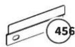
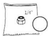
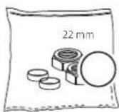
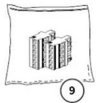


| 1 | Indoor unit | 7 | Insulation material (for refrigerant lines indoor unit) |
| 2 | Outdoor unit | 8 | Field charge sticker |
| 3 | Low loss header | 9 | Plug-in connectors (5 pole for X13 and 6 pole X2) |
| 4 | Indoor unit wall hanging bracket | 10 | Installation- and user manuals |
| 5 | Flare nut 1/4" (refrigerant liquid line) | 11 | Warranty card |
| 6 | Compression nut and 22mm olive (2x) |
3.1 Required components
The number of components required for installing the hybrid heat pump system depends on the installation situation. In addition to the standard items included, an overview of the general required components is provided below:
| Hydronic | ||
| Intergas magnetic system filter | 22 mm | In the return system water pipework to the indoor unit (required) |
| Spring loaded non-return valve (full bore) | 22 mm | In the heating return pipework to the boiler (required) |
| Electrical | ||
| Three-pole isolator switch | For isolating the 230V AC power to the outdoor unit. The three-pole isolator switch to be used must have the following:► Contactor opening distances of at least 3 mm. | |
| 4-wire cable (N, L, 3, ⊕) 4 x 1.5 mm2 | Power and switched live cable from the indoor unit to the outdoor unit. The cable to be used must have the following properties:► Cannot be smaller in diameter than those specified adjacent (in accordance the electrical regulations BS7671).► Must be suitable for outdoor use with a core thickness of least 1.5 mm and a maximum diameter of 14.5 mm. | |
| 2-wire low-current signal cable | 2 x 0.8 mm2 For the connection of the indoor unit to the room thermostat | |
| 2-wire low-current signal cable | 2 x 0.8 mm2 For the connection between the indoor unit and the existing boiler | |
3.2 Accessories
Original Intergas accessories can be ordered separately at your local stockist. Instruction about the correct way to assemble and use these accessories are provided with the product ordered and therefore have not been included within this installation manual.
 |  |  |  |
| Art. no. 090064Outdoor sensor set | Art. no. 032034 (white)Art. no. 032044 (black)Comfort Touch thermostat+ Gateway | Art. no. 030104 (white)Art. no. 030114 (black)Comfort Touch thermostat | Art. no. 032114Gateway |
 |  |  |  |
| Art. no. 090897System Filter incl. spigotisolation valve | Art. no. 066034Flow sensor type 200service set | Art. no. 066074Copper low loss headermanifold 22mm | Art. no. 066024Wilo pump replacementset |
 | 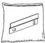 | 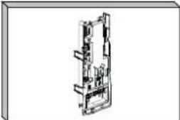 | 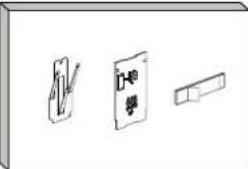 |
| Art. no. 090024Non return valve setX-serie | Art. no. 066084Wall hanging bracket | Art. no. 066004PCB Controllerreplacement set | Art. no. 066014HMI-PCBreplacement set |
 | 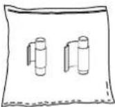 | ||
| Art. no. 066044NTC Temperature sensorclip on 22 mm (x2) | Art. no. 066054NTC Refrigeration sensorset clip on 6mm/12mmincluding wiring loom toX6 connector |
This manual contains the necessary information for the installation, troubleshooting and maintenance of the Intergas hybrid heat pump system. Read this manual carefully before installing, opening or performing maintenance work on the unit.
Intergas shall not be held liable for any consequences resulting from the following, if not performed in accordance with this manual: incorrect installation, improper troubleshooting, changes without permission from Intergas, incorrect operation or unnecessary maintenance work.
To prevent unsafe situations and to avoid possible claims, all instructions within this manual must be followed at all times.
Maintenance must be carried out at the time and frequency specified in §13. Use original parts only for replacement.
The Intergas hybrid heat pump system is an energy-saving and environmentally friendly system, intended for the heating and supply of hot water for the CH system. The system generates energy from the outside air and consists of:
▶ the indoor unit
▶ the outdoor unit
The Intergas hybrid heat pump system complies with the European directives and additional national regulations as indicated by the CE markings. The corresponding declaration of conformity can be requested from Intergas Heating Ltd.
The system includes the following features:
- Advanced control: this control is built into the indoor unit it controls and communicates with the outdoor unit as well as the boiler. It controls and monitors the system using various settings for heating of the CH system. The settings are configured by the installer and the user via the Wi-Fi control panel or the Intergas app.
- High-quality, efficient compressor.
- Working range of -15°C to +25°C .
4.1 General principle
![graph TD A["Boiler"] --> B["LrP modulating pump"] B --> C["Built-in filter expansion vessel"] C --> D["Indoor unit"] D --> E["Thermostat"] E --> F["Outdoor unit"] F --> G["Condensator drain"] D --> H["Remote expansion vessel option"] H --> I["Non-return valve (required)"] I --> J["Low loss header"]…](/content/2026/06/1395408/images/c535f9d050bc6b198ac535eca94a78f0c6f6671f739ce503b40e39d434fec313.jpg)
- Components marked with an (*) are offered as optional accessories; see §3.2.
- Components marked with an (+) are mandatory items which can be found in accessories; see §3.2.
- The indoor unit can be installed to either the right or left of the boiler.
4.2 Energy label Xtend hybrid heat pump system
In accordance with European ErP Directive (Energy-related Products), all new hybrid heat pump room heaters must meet minimum energy performance requirements.
There is an European energy label on the Xtend hybrid heat pump system that contains specific information about the energy efficiency class (of the CH), its noise level and capacity.
The Xtend hybrid heat pump system has an A ++ label for low temperature (35°C).
The comprehensive product sheet can be found in §14.

5.1 Indoor unit
| Technical information Unit | Xtend-HB-CUSP05 | |
| Operating temperature range °C | +7 °C to +40 °C | |
| Water in heating mode °C | +7 °C to +70 °C | |
| Maximum flow volume l/min | 30 | |
| Dimensions (H x W x D) mm | 557 x 163.5 x 275 | |
| Weight | kg | 10 (empty weight) |
| Protection category | IPX1 | |
5.2 Outdoor unit
| Technical information Unit Xtend-HB-AWHPSP05 | ||
| Operating temperature range (heating) °C -15 °C to +25 °C | ||
| Dimensions (H x W x D) mm 689 x 968 x 367 | ||
| Weight (net) kg 43 | ||
| Protection category IPX4 | ||
5.3 Common specifications
| Technical information Unit Value | ||
| Connection voltage/Frequency | VAC/Hz | 230/50 |
| Maximum electrical power consumption | kW | 1.8 |
| Maximum amperage | A | 7.8 |
| Refrigerant type | R32 | |
| Refrigerant GWP/ CO2 equivalent | 675/0.574 | |
| Refrigerant fill level weight | kg | 0.85 |
5.3.1 Heating mode: L7/W35 measured in accordance with EN 14511-2
| Technical information Unit Value | ||
| Nominal heat output kW 5.04 | ||
| Coefficient of Performance (COP) 4.68 | ||
| Electrical power consumption kWe 1.08 | ||
| Nominal water flow rate ( ΔT = 5K ) | m3/h | 0.89 |
5.3.2 Heating mode: L2/W35 measured in accordance with EN 14511-2
| Technical information Unit Value | ||
| Nominal heat output kW 3.31 | ||
| Coefficient of Performance (COP) 3.00 | ||
| Electrical power consumption kWe 1.10 |
5.3.3 Heating mode: L7/W45 measured in accordance with EN 14511-2
| Technical information Unit Value | ||
| Nominal heat output kW 5.01 | ||
| Coefficient of Performance (COP) 3.56 | ||
| Electrical power consumption kWe 1.41 |
5.3.4 Technical parameters in accordance with EN 14825
| Technical information Symbol Unit Value | |||
| Supplier | Intergas Heating LtdUnit 2Easter ParkWorcester RoadKidderminsterDY11 7AR | ||
| Model Xtend 5 | |||
| Air-water heat pump Yes | |||
| Water-water heat pump No | |||
| Brine-water heat pump No | |||
| Low-temperature heat pump Yes | |||
| Equipped with an additional heating unit Yes | |||
| Heat pump combination | No | ||
| Nominal heat output (*) | Proted | kW | 5 |
| Declared heating capacity for part load, at an indoor temperature of 20 °C and outdoor temperature Tj | |||
| Tj = -7 °C | Pdh | kW | 3.1 |
| Tj = +2 °C | Pdh | kW | 2.6 |
| Tj = +7 °C | Pdh | kW | 2.0 |
| Tj = +12 °C | Pdh kW 2.4 | |
| Tj = bivalent temperature | Pdh kW 3.3 | |
| Tj = extreme operating temperature | Pdh kW 3.0 | |
| Bivalent temperature | Tbiv °C | -2 |
| Technical information Symbol Unit Value | |||
| Cycling interval capacity for heating Pcych kW n/a | |||
| Loss coefficient (**) Cdh °C 0.9 | |||
| Seasonally dependent energy efficiency for space heating η | 5 | % | 160 |
| Declared Coefficient of Performance (COP) for part load, at an indoor temperature of 20 °C and outdoor temperature Tj | |||
| Tj = -7 °C COPd - 2.69 | |||
| Tj = +2 °C COPd - 3.45 | |||
| Tj = +7 °C COPd - 6.66 | |||
| Tj = +12 °C COPd - 8.96 | |||
| Tj = bivalent temperature | COPd - | 3.09 | |
| Tj = extreme outdoor temperature | COPd - | 2.53 | |
| Cycling interval efficiency | COPcyc - | n/a | |
| Extreme operating temperature for air-water heat pumps | TOL | °C | -10 |
| Extreme operating temperature of water for heating | WTOL | °C | 45 |
| Energy consumption in statuses other than active mode | |||
| Off mode | POFF kW | 0.011 | |
| Thermostat off mode | PTO kW | 0.011 | |
| Stand-by mode | PSB kW | 0.011 | |
| Crankcase heater mode | PCK kW | 0.000 | |
| Other items | |||
| Output control | Variable | ||
| Sound output level (indoor/outdoor) | LWA | dB(A) | 32/49 |
| Annual energy consumption | QIR | kWh | 2438 |
| Nominal airflow (outdoor) | m3/h | 1783 | |
(*) For space heating devices with a heat pump and combination heating devices with a heat pump, the nominal Prated heat output is equal to the design load for heating Pdesignh, and the nominal heat output of an additional heating device Psup is equal to the additional heating capacity sup(Tj).
** If Cdh is not determined via measurement, the standard loss coefficient Cdh = 0.9
The indoor unit is designed for installation within the property and must not be subjected to external elements, it must be connected to an ErP classified combination boiler, also situated internally.
The indoor unit is the heart of the hybrid heat pump system. It acts as a distribution station, connecting and controlling the outdoor unit and the combination boiler during a heating demand.
The indoor unit complies with electrical protection class IPX1.
6.1 Function
The indoor unit is the distribution and control station for the entire hybrid heat pump system. This means that all of the controls in the system run through this device. The indoor unit is equipped with an electronically modulating circulation pump, a plate heat exchanger and the control unit.
In conjunction with the outdoor unit (and if necessary the combination boiler, the indoor unit ensures that the desired heating water temperature can be achieved.
During extremely low outdoor temperatures if the indoor unit cannot achieve sufficient output to satisfy the heating demand, the combination boiler will receive a signal from the indoor unit and start generating additional heat to reach the desired water temperature.

6.2 Operation
The indoor unit is equipped with a multicolour LED strip and a control button. The LED lighting indicates the status of the system using different colours; see §10.1.
One of the control button functions is to establish a Wi-Fi connection, to link a smartphone or tablet to the device. This allows you to track the behaviour of the hybrid heat pump system. This control screen also provides access to various functions, malfunction information and user history; see §10.2 and §10.3.

6.3 Rating plate indoor unit
The rating plate is located on the underside of the appliance and includes the following information:
Product type
Serial number
QR-code
Electrical mains supply
Electrical power
Electrical current
IP Rating
▶ Operating pressure
Weight
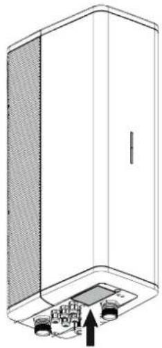

The serial number will be displayed in 2 sections seperated by (-). The first part is the country code or part number, made up of 6 digits. The second part is the unique serial number, made up of 10 digits.
| Air-to-water heat pump Xtend-HB-CUSP05 | XXXXXXXX-XXXXXXXXXX 20xx |  |
| Power supply / frequency | 230V~/50Hz | |
| Maximum input power | 1,8 kW | |
| Maximum input current | 7,8 A | |
| Protection rating | IPX1 | |
| Maximum allowable water pressure | 3 bar | |
| Netto weight | 10 kg | |
| Intergas Heating Ltd. Unit 2, Easter Park Worcester Road Kidderminster, DY11 7AR |  Made in the Netherlands Made in the Netherlands |

The view below shows the interior of the indoor unit without its usual insulation.
6.5 Dimensions and connections of the indoor unit

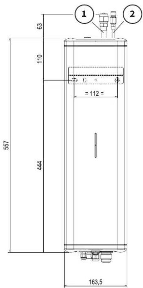

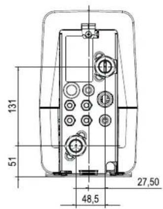
| Connections | ||
| 1 Refrigerant gas line 1/2" | ||
| 2 Refrigerant liquid line 1/4" | ||
| 3 | Mains supply and communication cable to outdoor unit | M20 (gland) |
| 4 | Hot system water flow line from the indoor unit to the CH circuit | ∅22 mm (compression) |
| 5 | Cold system water return line from the CH circuit to the indoor unit | ∅22 mm (compression) |
| 6 Indoor unit mains supply cable M16 (gland) | ||
7.1 Function
The outdoor unit is designed for installation outside of the property and must be connected to and used in conjunction with the indoor unit detailed in §6.0
The outdoor unit complies with electrical protection class IPX4.
The outdoor unit extracts energy from the external air and transfers it to the indoor unit.
The compressor speed varies to ensure that the correct amount of energy is delivered. The fan is also speed controlled, modulating its speed to meet the heating demand. This ensures the energy consumption is as low as possible for maximum efficiency.

7.2 Main components outdoor unit

The view below shows the interior of the outdoor unit without the casing.

7.3 Dimensions and connections outdoor unit

| Connections | ||
| 1 | Refrigerant gas line 1/2" | |
| 2 | Refrigerant liquid line 1/4" | |
| 3 | Mains supply and switched line connection (from the indoor unit) | N, L, 3, ⊕ |
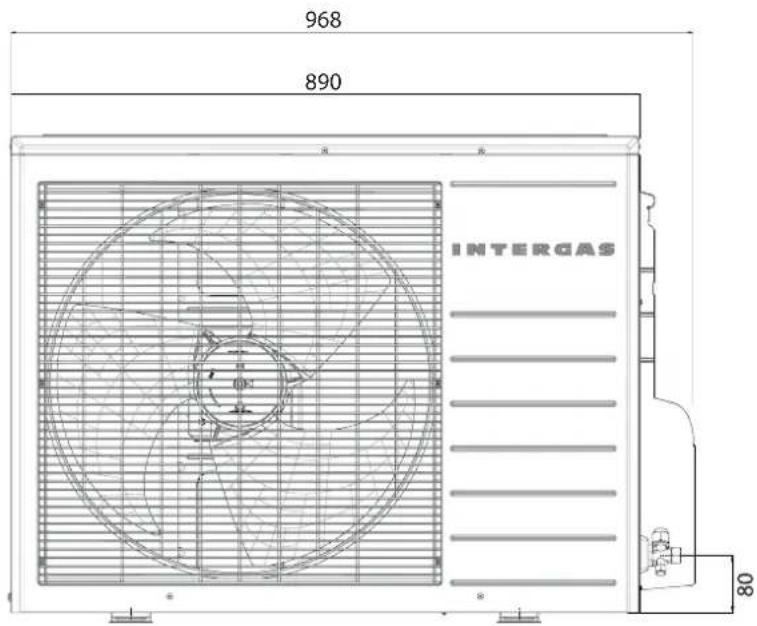

7.4 Rating plate outdoor unit
The rating plate is located on the right side of the unit and includes the following information:
Product type
▶ Operating pressure
▶ Refrigerant type
▶ Refrigerant quantity
Electrical mains supply
Electrical power
IP Rating
Weight
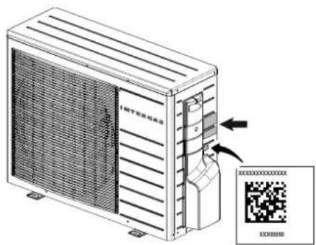
| Air-to-water heat pump Xtend-HB-AWHPSP05 | ||||
| Power supply/frequency | 230V~ / 50Hz | |||
| Maximum input power | 1,8 kW | |||
| Maximum input current | 7,8 A | |||
| Protection rating | IPX4 | |||
| Refrigerant type | R32 | |||
| Refrigerant GWP / CO2 equivalent | 675 / 0,574 | |||
| Refrigerant charge | 0,85 kg | |||
| Maximum allowable pressure (H/L) | 4,2 MPa | |||
| Net weight | 43 kg | |||
 |  |  |  |  |
| Heating | A7/W35 | A7/W45 | A2/W35 |
| Capacity [kW] | 5,04 | 5,01 | 3,31 |
| Current [A] | 4,7 | 6,1 | 4,8 |
| Power input [kW] | 1,08 | 1,41 | 1,10 |
| COP | 4,68 | 3,56 | 3,00 |
| Test conditions according to EN 14511-2:2018 | [7000] | ||
| Made in IndiaContains Fluorinated greenhouse gases covered by the Kyoto protocol.Hermetically sealed refrigerant System. | |||
8.1 Installation overview
![graph TD A["Boiler"] --> B["Indoor unit"] B --> C["Thermostat"] C --> D["Outdoor unit"] D --> E["Intergas fan"] subgraph Boiler F["RL1"] --> G["RL2"] H["RL3"] --> I["RL4"] J["RL5"] --> K["RL6"] L["RL7"] --> M["RL8"] N["RL9"] --> O["RL10"] P["RL11"] --> Q["RL12"] end subgraph Indoor unit R["L01"] -->…](/content/2026/06/1395408/images/3c70f52065c7ab3ec408bd618151a281e32c3da083bd81d15df683e4db283229.jpg)
- Components marked with an (*) are offered as optional accessories; see §3.2.
- Components marked with an (+) are mandatory items which can be found in accessories; see §3.2.
The system must have a minimum volume of heating water. The standard flow is 15 l/min. It is advisable to install a central heating buffer tank to comply with the minimum flow, to prevent the outdoor unit from switching on and off too often and to ensure that there is sufficient energy to complete the defrost cycle of the outdoor unit when required.
Below are two possible installation options:
Buffer tank (install parallel)
When using a buffer tank:
▶ Has a minimum capacity of 40 litres.
▶ Install a CH-pump after the separation from the buffer tank, see option A. (Connect the wiring to connector X13 (contacts 4 and 5) on the indoor unit and set parameter
P068 to "10". Also see §8.8.10
Intermediate vessel (install in series)
It is advisable to install an insulated intermediate vessel with a minimum volume of 20 litres, see option B.
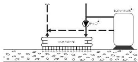
Option A
![graph TD A["Intermediate vessel"] --> B["Chirculation"] B --> C["CH circuit"] C --> D["Heating oil layer"] D --> E["Heating Oil Tank"] E --> F["Heating Oil Tank"] F --> G["Heating Oil Tank"] G --> H["Heating Oil Tank"] H --> I["Heating Oil Tank"] I --> J["Heating Oil Tank"] J --> K["Heating Oil Tank…](/content/2026/06/1395408/images/c1d117af21fc034374d8dd8b81333585ac74805074ca3b103f59247b647529d9.jpg)
Option B
| Lines | ||
| Tag | Description | Notes (minimum diameters) |
| L01 | Cold system water return line from the CH circuit to the indoor unit 2 | 2 mm (compression) |
| L02 | Hot system water flow line from the indoor unit to the CH circuit | 22 mm (compression) |
| L03 | Low loss header return line to the boiler | 22 mm (compression) |
| L04 | Boiler flow line to the low loss header | 22 mm (compression) |
| L05 | Refrigerant line (gas) | 1/2 inch, flared joint union (must be insulated) |
| L06 | Refrigerant line (liquid) | 1/4 inch, flared joint union (must be insulated) |
| Fittings - Instrumentation | ||
| Tag Description Signal | ||
| T01 NTC (clip-on 1/2") T (°C) Refrigerant line (gas) | ||
| T02 NTC (clip-on 1/4") T (°C) Refrigerant line (liquid) | ||
| T03 NTC (clip-on 22mm) T (°C) Indoor unit flow | ||
| T04 NTC (clip-on 22mm) T (°C) Indoor unit return | ||
| T05 NTC (clip-on 22mm S1 flow integral to boiler) T (°C) Boiler heating flow to low loss header | ||
| T42 Outdoor sensor and housing (optional) | T (°C) outdoor | |
| T43 Remote flow temperature sensor (optional) T (°C) Heating system flow | ||
| P01 System pressure sensor (integral to boiler) | ||
| Fittings - Process | ||
| Tag Description Notes | ||
| LLH01 Open distributor (Low loss header) | ||
| V01 Venting Manual air vent top left of the indoor unit | ||
| V02 System filter (required) Positioned in the CH system return line to the indoor unit | unit | |
| V03 Non return valve (required) | Positioned in the boiler return line (L03) from the low loss header to the boiler. Ensure no non-return valve has already been installed (i.e. to prevent thermo-syphoning). | |
| V04 Venting Manual venting top left of the boiler | ||
| V05 Pressure relief valve | Built into the boiler, the discharge pipework must be routed and terminated as stated within the installation manual or BS 6798 | |
| V06 Filling valve connection For filling the system / CH water | ||
| V07 | Full-flow ball type isolation valve (optional) | To assist when cleaning or flushing the system filter |
| V08 | Gas line isolation valve 1/2" flared joint union (service connection point) | Service point for refrigerant actions |
| V09 Liquid line isolation valve 1/4" flared joint union | ||
| Pm01 Indoor unit CH pump ErP modulating | Primary pump for the CH system installation | |
| Pm02 Boiler CH pump ErP modulating | Secondary pump for the CH system installation | |
| Pm03 External pump for a buffer vessel (optional) | ||
| HE01 | Indoor unit plate heat exchanger | |
| HE02 | Boiler heat exchanger | |
8.2 Distance between the indoor and outdoor units

NOTES
▶ Observe the recommended connection lengths between the indoor and outdoor units in order to ensure the system functions correctly.
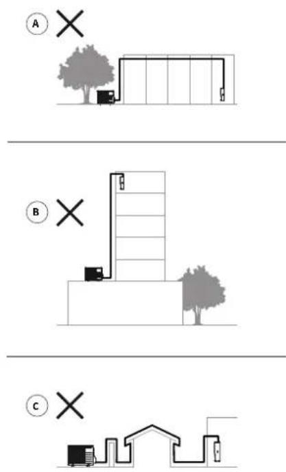
A Minimum/maximum length of refrigerant lines
B Maximum height difference between horizontal lines.
C Maximum number of 90° bends, this applies to the entire pipework (including oil syphon) and not per pipe.
| ABC | ||
| 3 to 25 m 10 m x 10 |
Oil return measures
Use an S-shaped oil syphon in the gas pipe to the outdoor unit if it is more than 5 meters higher than the indoor unit, see the adjacent illustration.
Avoid long, complicated routes between the indoor unit and outdoor unit, see the adjacent illustration.
A Too long
B Too high
C Too many bends

8.3 Installing the indoor unit
8.3.1 Installation location
The indoor unit must be mounted level on a wall with sufficient load-bearing capacity to support the appliance when it is filled with water.
If the wall construction is not solid i.e. brick or block, the sound of the unit may resonate.
A switched fused spur must be located within 2 metres of the device.
The indoor unit should be placed near the boiler. Take this into account when planning the installation and pipework.
To prevent the indoor unit from freezing, it must be installed in a frost-free environment this would include any loft spaces etc.
Ensure that the indoor unit is easily accessible by maintaining the adjacent minimum clearances.
| Further dimensions | |
| D* 600 mm | |
8.3.2 Mounting the indoor unit
- Secure the mounting bracket to the wall horizontally using appropriate fastening equipment (not included). Please ensure it is level.
- Lift the indoor unit over the mounting bracket and slide it down, ensuring it is correctly located.


- Mount the wall bracket

- Installing the indoor unit
8.3.3 Removing and replacing the front cover
Before carrying out various types of work on the appliance, the front cover must be removed. The front cover is removed as follows:
▶ Loosen the screw (1) under the device using a Pozi screwdriver.
▶ Gently pull the front cover (2) forwards at the bottom, and then slide upwards.

Replacing the front cover
The front cover is replaced as follows:
▶ Return the front cover (3) to its original position by lowering onto the top of the indoor unit and then gently pushing the bottom backwards until it locates correctly.
▶ Tighten the screw under the device using a Pozi type screwdriver.

8.4 Water-side connection

NOTES
For a complete overview of the system, see §8.1.
▶ Connect the indoor unit to an ErP compliant boiler.
▶ Open vent conversions are not suitable for connecting to the Xtend.
The indoor unit, outdoor unit and existing boiler must be positioned as close together as possible.
The pipework distance between the indoor unit and the boiler must be kept as short as possible.
The pipework must be drained down before installation to prevent spillages and damage to the surroundings.
There must be a 400 µm filter installed in the return heating line to the indoor unit, the Intergas system filter is preferred.
▶ Install shut-off valves between the indoor unit and the heating circuit in order to allow for maintenance work and other interventions.
▶ Install a full flow non-return valve in the return pipe to the boiler.
The entire system must be equipped with an expansion vessel. (Some boiler models incorporate a vessel, however the capacity should be checked against the system volume)
The boiler incorporates a suitable 3bar PRV.

8.4.1 Connecting the indoor unit and the boiler using the low loss header

NOTES
The indoor unit should be installed as close as possible to the boiler. Below are two installation examples.
Indoor unit right Indoor unit left


- Drain the heating system to eliminate spillages and damages.
- Determine the position of the pipework and connections.
- Connect the return pipe CH-water (L01) to the indoor unit using the supplied ∅22mm compression connection and install the Intergas system filter (V02) incl. spigot isolation valve (V07).
- If required, install an additional isolation valve (V08) in the pipework above the filter to enable maintenance work (optional).
- Install the low loss header (LLH01) vertically under the indoor unit using the supplied compression connector.
- Install the return pipework (L03) from the upper side connection of the low loss header to the boiler, which must include a full flow non-return valve (V03).

IMPORTANT
▶ Ensure the full flow non-return valve (V03) is in the correct directional flow.
- Install the flow pipework (L04) from the lower side connection of the low loss header to the boiler.
- Connect the central heating pipework (L02) from the bottom connection of the low loss header to the heating system flow.
- Fill the system, check the pipework and the connections for leaks.
The following set is available:
• Filter set; art. no. 090897
| Key Description | |
| L01 | Return pipe CH-water |
| L02 | Flow pipe CH water |
| L03 | Return pipe Boiler |
| L04 | Flow pipe Boiler |
| V02 | System filter (required) |
| V03 | Full flow non-return valve(required) |
| V07 | Isolation valve (required) |
| V08 | Isolation valve (optional) |
| LLH01 | Low loss header |

Intergas system filter (V02)
Spigot isolation valve (V08)
Drain/Dosing valve
8.5 Setting up the outdoor unit
8.5.1 Points of attention for location
The outdoor unit must be installed outdoors and on a permanent load bearing surface that is suitable for the weight of the unit.
The unit must be mounted on anti-vibration feet (sold separately).
▶ The unit location must be away from any external sources of heat radiation or open flames.
▶ If possible place the outdoor unit in a shady location away from direct sunlight.
There must not be any obstacles/barriers in front of or near the inlet and outlet side of the unit.
Adverse weather conditions such as high wind, rain, snow or even fallen leaves can effect the efficiency or operation of the outdoor unit, so care should be taken when siting it, open areas should be avoided if at all possible.
During defrost mode it must be possible to drain condensate water away from the unit base without it freezing, the water should be piped to a suitable drain or soakaway where it will not present a slip hazard from freezing.
When choosing a suitable location for the outdoor unit please ensure that there is sufficient clearance around the unit housing; see §8.5.3. When doing so please ensure that there is clear access to complete the installation and also any further maintenance work (1).
The side panel and any removed covers must be correctly reinstalled after the work has been completed. Incorrect replacement can result in ingress from rain, spray water, vermin etc. wich can lead to faults or irreparable damage to the outdoor unit.
8.5.2 Transport

IMPORTANT
▶ Do not touch the outdoor evaporator fins with fingers, hands or objects. This may damage the exchanger and/or cause injury.
Leave the transportation packaging around the outdoor unit in place for as long as possible to prevent external damage. If it is necessary to hoist the unit, this must be done before the transportation packaging is removed. An approved hoisting strap suitable for the weight to be lifted is required for hoisting. To prevent damage, soft protective material must be placed between the straps and the corners of the outdoor unit. A hook cannot be used for hoisting the indoor unit.
Please note: the gross weight of the outdoor unit is 46 kg.
8.5.3 Installing the outdoor unit
▶ Provide sufficient space around the outdoor unit for maintenance and repair work to be carried out safely.
▶ Ensure that the distance between ground level and the underside of the outdoor unit is at least 150 mm, to prevent the unit from sucking in splash water, snow drifts or street dirt.
There should be no less than 150 mm of free space from the back of the outdoor unit.

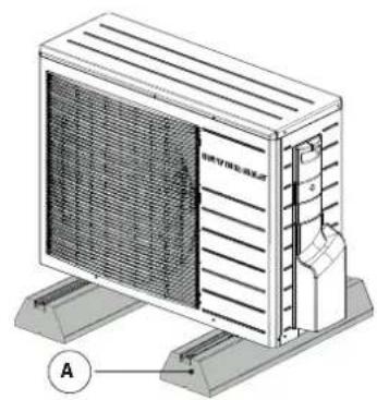
For noise reduction purposes, the outdoor unit must be level and placed on suitable anti vibration footrests (A).
▶ Preferably place the outdoor unit on a gravel bed, equipped with an soakaway pit for draining off condensation water. The condensation drain hose or pipework must be insulated with a UV colorant pipe lagging to prevent freezing.

IMPORTANT
Placing the outdoor unit on a solid base or flat roof can lead to its underside or the outlet side of the fan freezing, especially during the winter months.
▶ If the outdoor unit is mounted on a flat roof, we recommend using longer anti vibration footrests to prevent it from blowing over.
On a wall
If the outdoor unit is being secured to the facade, do the following:
▶ Make sure that the wall is sturdy enough to bear the weight of the outdoor unit.
▶ Choose a wall with enough mass to dampen any vibrations.
▶ Ensure that the outdoor unit is easily and safely accessible for maintenance work, if base is above 1000 mm then a purpose made permanent platform must be present.
▶ Make sure that there is enough space around the outdoor unit, so that it can move air without any restrictions. There should be no less than 150 mm of free space from the back of the outdoor unit.
▶ Condensation water must drain correctly, use the supplied drain connection elbow (A) and flexible hose (B) to help facilitate the connection to a soakaway or drain.
Connecting the drain plug:
- Clip the drain plug into the opening at the bottom of the outdoor unit.
- Connect the flexible drain hose onto the drain plug.
NOTE: If the outdoor unit is placed directly over a gravel bed type soakaway then the drain connection (A) can be omitted allowing the condensate water to drip directly out the housing onto the gravel.

8.6 Refrigerant connections
8.6.1 Points of attention for refrigerant lines

IMPORTANT
▶ Refrigerant work can only be performed by a registered F-gas or REFCOM installer.
All F-gas actions must be performed according to the F-gases regulation (EU) 517/2014.
The outdoor unit is charged with 0.85 kg of R32 refrigerant before leaving the production facility.

IMPORTANT
▶ Make sure that the refrigerant lines have minimal hydraulic resistance.
The distances of the liquid and gas lines running between the outdoor unit and indoor unit must be kept as short as possible (between 3 metres and 25 metres), the external section of the pipework must be kept to a minimum.
The inside of the refrigerant lines must not be contaminated. Ensure that the lines have been cleaned before the final connection.
The lines must be protected from physical damage using a proprietary pipe cover.
▶ Use rubber lined support clamps or spacers to keep the lines from coming into contact with any surfaces.
▶ All of the lines must be well insulated with Class 0 rubber or similar quality insulation (pre-insulated coils available).
The lines must be accessible for maintenance work.
If work using heat sources must be performed, then suitable a hot works permit must be completed and issued prior to commencing. A suitable fire-extinguishing must be on site during these works.
▶ No ignition sources are permitted for use near exposed refrigerant gas lines. This poses a risk of fire or explosion.
▶ Use the correct tools for cooling connections: connections made incorrectly will have to be remade.
▶ Check the cooling connections for leaks with a leak detector whilst pressure testing with Oxygen free Nitrogen. Conduct a second leak test after the system has been filled with refrigerant using a suitable leak detection fluid or calibrated electronic sniffer (R32).


8.6.2 Making refrigerant connections to the indoor unit

IMPORTANT
▶ Prevent internal connection lines from twisting by using a suitable spanner to secure the refrigerant coupler.
- Cut the refrigerant lines to the correct lenght using a pipe cutter (not a hacksaw) then fully deburr the edges.
Liquid line (see example):
- Unscrew and remove the cap from the schrader valve to the 1/4 " liquid line 1/4 " (A).
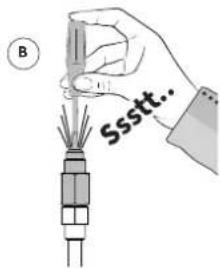
- Check to ensure that the indoor unit is leak tight. Carefully insert a screwdriver or pointed tool into the schrader valve. You should hear a hissing sound when you do this which indicates that the unit is leak tight; see (B). (The unit is pre-charged with Oxygen free Nitrogen which is inert and not a greenhouse gas).
- Remove the schrader valve and the copper seal ring, then dispose of them responsibly (C).
- Remove the flare nut for the liquid line from the accessory bag supplied with the unit (D).
- Place the nut onto the 1/4 " liquid line and then flare the end using a proprietary flaring tool (E).
▶ Instead of flaring the line yourself, a flare press-fit or flare solder adapter can be used.
- Apply a smear of compressor oil or sealing fluid to the surface of the flare adapter to be sealed as this will improve the seal.
- Connect the liquid line to the indoor unit via the flare connection.
- Secure the connections by tightening them to the required torque setting.
- ¼" nut: 14-18 Nm
Gas line:
- Remove the flare nut from the 1/2 " gas line. Save the nut and dispose of the copper sealing ring.
- Place the nut onto the 1/2 " gas line and then flare the end using a proprietary flaring tool (F).
▶ Instead of flaring the line yourself, a flare press-fit or flare solder adapter can be used.
- Apply a smear of compressor oil or sealing fluid to the surface of the flare adapter to be sealed as this will improve the seal.
- Connect the gas line to the indoor unit via the flare connection.
- Secure the connections by tightening them to the required torque setting.
- ½" nut: 49-61 Nm

IMPORTANT
Place the included insulation material around the lines beforehand so that it can later be pushed down over the refrigerant connectors; see (G) but also §8.6.7.

![graph TD A["Step A"] --> B["Recycle Bin"] B --> C["Component"] C --> D["Recycle Bin"]](/content/2026/06/1395408/images/4a74c50011b0a9d3cfb08e26a637fe3bb3253995c98121edcc92949d1c7a342b.jpg)
![graph TD A["Top Component"] --> B["Bottom Component"] B --> C["Recirculation of Waste Bin"] C --> D["Recirculation of Waste Bin"]](/content/2026/06/1395408/images/7129e19a5089117a6d8031dd80a11fc28da3b24b76487a6fe3496d94dba17f07.jpg)


8.6.3 Making refrigerant connections to the outdoor unit
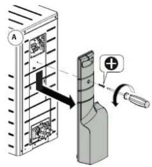
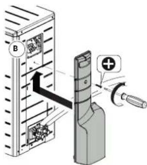
- Remove the side panel from the outdoor unit (A).
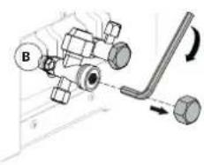
- Remove the 19 mm lockshield caps from the service valves and check that they are closed using a 5 mm Allen key (B).
- Unscrew the 1/2" and 1/4" flare nuts from both service valves (C).
- Cut the now installed refrigerant lines running from the indoor unit to the desired length using a pipe cutter and deburr them.
- Place the nuts onto the refrigerant lines and then flare the lines.
▶ Instead of flaring the line yourself, a flare press-fit or flare solder adapter can be used.
-
Apply a smear of compressor oil or sealing fluid to the surface of the flare adapter to be sealed as this will improve the seal.
-
Connect both of the refrigerant lines via the flare connections.
-
Secure the connections by tightening them to the required torque setting.
- ¼" nut: 14-18 Nm
- ½" nut: 49-61 Nm

IMPORTANT
▶ Prevent internal connection lines from twisting.

8.6.4 Strength test and Tightness testing
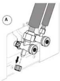
- Using a 5 mm Allen key check that the service valves are fully closed, then remove the 14 mm sealing cap from the Schrader valve on the 1/2 " gas line service valve (A)
2. Appropriate PPE must be worn at this stage.
-
Using a certified removal tool remove the schrader valve and keep safe in a dust free environment, then using OFN (Oxygen free Nitrogen) connected via a pressure regulator slowly raise the pressure to 42 bar in increments of 5 bar (B) checking for leaks (listen for hissing sound) or use leak detection fluid that is suitable for use on refrigeration, (repair if required). Hold the pressure for 2 minutes then gently lower the pressure to 10 bar by slowly venting the Nitrogen to a well ventilated area (C).
-
Check that the connections on the indoor and outdoor unit are leak tight.
▶ Check that the pressure on the meter set is not going down
▶ Use leak-detecting spray that is suitable for hydrocarbon gases.
▶ Any leaks must be repaired and re-tested before continuing.
- Once complete and tightness proved slowly releasethe notrogen to a well ventilated area.

IMPORTANT
For safety reasons when carrying out the strength and tightness tests to BS EN 378 appropriate PPE must be worn. Venting of Nitrogen must be done in a well ventilated place, away from any area where the vented gas could produce flying dust or objects. In poorly ventilated areas Nitrogen can displace the air, leading to an Oxygen deficient atmosphere where asphyxiation could occur.


8.6.5 Creating a vacuum in the refrigerant lines
- Connect the vacuum pump to the vacuum gauge on the service valve using the certified puller as a connection set, ensure that both service valves are still closed (A).
- Create a vacuum in the refrigerant lines below 500 microns.
- Close the valve to the vacuum pump, and switch the pump off read the pressure on the vacuum gauge.
- The vacuum gauge must not rise above 2500 microns (2.5 Torr) within 30 minutes.
- Repeat steps 2 and 3 if the pressure rises above 2500 microns.
- If the test fails again break the vacuum with nitrogen then complete a further tightness test at 10 bar to find the leak and repair, then repeat steps 1 to 4.
- Using a certified removal tool replace the schrader core as removed in §8.6.4.(3).
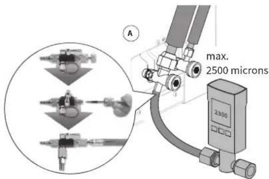
Using the certified core removal tool connect it to the service valve outlet, this allows connection of the vacuum gauge and service.
8.6.6 Refrigerant actions
- Open the service valve on the liquid line using a 5mm Allen key turning it anti-clockwise until you encounter firm resistance (A) (the system will start to fill with refrigerant).
- Replace the 19mm lockshield cap, tighten to 14-18 Nm torque.
- Open the service valve on the gas line using a 5mm Allen key by turning it anti-clockwise until you encounter firm resistance (A).
- Replace the 19mm lockshield cap, tighten to 14-18 Nm torque.
- Depending on the length of the refrigerant lines, it may be necessary to add more refrigerant. The minimum pipe length is 3 metres. The pre-filled refrigerant quantity in the outdoor unit is 850 grams. Follow the table below for longer refrigerant lines of 7 metres or more:
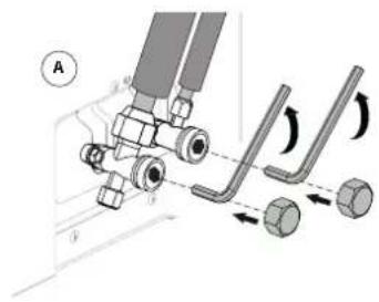
Ensure the service valves are back stopped before replacing the lockshield caps.
| Meters of pipe 1/2'' × 1/4'' | Additional filling(grams) | Total filling(grams) | Tons of C02equivalent |
| 3 0 850 0,574 | |||
| 4 0 850 0,574 | |||
| 5 0 850 0,574 | |||
| 6 0 850 0,574 | |||
| 7 25 875 0,591 | |||
| 8 50 900 0,608 | |||
| 9 75 925 0,624 | |||
| 10 90 940 0,635 | |||
| 11 105 955 0,645 | |||
| 12 120 970 0,655 | |||
| 13 135 985 0,665 | |||
| 14 150 1000 0,675 | |||
| 15 165 1015 0,685 | |||
| 16 180 1030 0,695 | |||
| 17 195 1045 0,705 | |||
| 18 210 1060 0,716 | |||
| 19 225 1075 0,726 | |||
| 20 240 1090 0,736 | |||
| 21 255 1105 0,746 | |||
| 22 270 1120 0,756 | |||
| 23 285 1135 0,766 | |||
| 24 300 1150 0,776 | |||
| 25 315 1165 0,786 |
Example adding refrigerant:
For pipes of 12 meters, 120 grams of refrigerant must be added. The total filling is then 970 grams. Pipe lenght is measured from the outdoor unit to the indoor unit as a pair and not individually
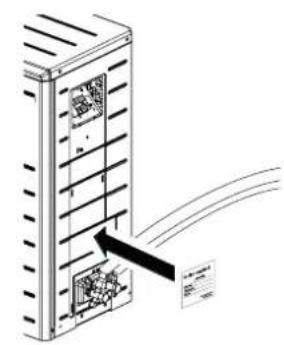
- Using a ball point pen complete the included field charge label.
- Attach the field charge label to the side panel of the outdoor unit as shown in the figure. This ensures the label is accessible for any attending engineers as per the F-Gas regulations.

NOTES
The field charge label should only be completed and attached if refrigerant has been added.

8.6.7 Insulating the refrigerant lines
- Fold or push the included insulation material (A) around each refrigerant line above the indoor unit. The lines must be insulated separately
- Secure the insulation material using insulation tape.

8.6.8 Emptying the meter set
The pump draining function (pumping out refrigerant, see §11.2.3.) can be used to empty the meter set. The following steps describe how the pump draining function works with regard to emptying the meter set within the outdoor unit, assuming that the liquid and gas lines have been connected from the outdoor to indoor unit and commissioned correctly.
When doing this, ensure that you are connected to the Wi-Fi control screen, §10.2.1.
- Close the service valve on the liquid line using a 5mm Allen key by turning it clockwise (A).
Please note: the gas line service valve must remains open to carry out the draining function task. - Connect a meter set to the gas line service valve using a Schrader core removal tool, having removed the core prior.
- Turn on the pump draining function using the control screen within the app.
▶ Via the service menu:
Click on 'Tools'
▶ Click on 'Pump out refrigerant'
▶ Select 'Start'
The system will now create a vacuum and move the refrigerant back into the outdoor unit.
-
Check the meter set to ensure the pressure is dropping at a pressure of 0 bar, all the refrigerant will have moved back into the outdoor unit.
-
Select 'Stop' on the Wi-Fi control screen.
-
Close the service valve on the gas line using a 5mm Allen key by turning it clockwise.
-
Replace the 19mm lockshield cap, tighten to 14-18 Nm torque.
-
Replace the Schrader core using the core removal tool and remove the meter ser replacing the 14mm sealing cap (A).
-
When completed replace the 19mm lockshield caps and the side panel on the outdoor unit (B).

Connect the meter set to the gas line service valve connection having removed the Schrader core prior.
8.6.9 Checking the refrigerant actions

IMPORTANT
▶ Keep the refrigerant lines as short as possible (min. 3 metres and max. 25 metres), §8.6.6.
▶ Correct system operation may be affected if too much refrigerant has been added.
▶ Excessive refrigerant must be recovered and recorded correctly.
The field charge label must be completed and attached to the outdoor unit when refrigerant has been added (for refrigerant lines of 7 metres or more), see §8.6.6.
▶ Conduct a second tightness test before leaving the location.
▶ Replace the side panel on the outdoor unit.
8.7 Making electrical connections
8.7.1 Points of attention for electrical installation

IMPORTANT
▶ Work on electrical connections must never be performed when the system is live and the safe isolation procedure must be completed.
For a complete overview of the electrical system, see §8.7.2.
▶ Always observe BS 7671 when carrying out any electrical work.
Electrical work may only be carried out by a qualified and registered electrician.
▶ After completing the safe isolation checks and before working on the appliance, please check the electrical cables for any wear, strain UV or rodent damage etc.
▶ Correct polarities must be observed when making 230v\~ electrical connections.
Electrical work on the outdoor unit must not be attempted whenever there is a possibility of precipitation, or water ingress of any kind.
8.7.2 Electrical installation overview
![graph TD A["HVAC Unit"] --> B["1"] B --> C["2"] C --> D["3"] D --> E["45"] E --> F["6"] F --> G["7"] G --> H["98"] H --> I["Remote Flow Temperature Sensor 141 (optional)"] I --> J["Gateway*"] J --> K["Thermostat*"] K --> L["Outdoor Temperature Sensor 142 (optional)"] L --> M["3 pole Isolator switch"…](/content/2026/06/1395408/images/c31ad652f476cb46c32df52dc907ba0cab69c8a8136e553e9cebd7b491f5242e.jpg)
Components marked with an (*) are offered as optional accessories; see §3.2.
| Wiring | |||
| No. Type Function Notes | |||
| 001 4 | x 1.5 mm2 - Mains and switch live cable | Mains power and switched live to the outdoor unit | Must be a 3 pole safe isolation switch near to the outdoor unit.See specification §3.1 |
| 002 2 | x 0.8 mm2 - Signal cable External outdoor sensor T42 | Optional for use with a weather-dependent control setting. See §8.8.6 and §11.5 | |
| 003 2 | x 0.8 mm2 - Signal cable Indoor temperature setpoint | Polarity not important when using OpenTherm connectivity | |
| 004 2 | x 0.8 mm2 - Signal cable | Remote flow temperature sensor T43 | Optional for use with a weather-dependent control setting. See §8.8.7 and §11.5 |
| 005 3 | x 1.5 mm2 - Mains cable Indoor unit power supply | 10 amp rated fuse 230V~ / 50Hz | |
| 006 2 | x 0.8 mm2 - Signal cable Communication with boiler | OpenTherm connectivity | |
| 007 3 | x 0.75 mm2 - Mains cable Boiler power 3 amp | rated fuse 230V~ / 50Hz | |
| 008 3 | amp switched fused spur Power supply to boiler | 230V~ / 50Hz | |
| 009 10 | amp switched fused spur | Power supply to Indoor and outdoor units | 230V~ / 50Hz |
8.7.3 Electrical schematic (indoor unit)
![graph TD A["CONTROL UNIT"] --> B["Refrigerant liquid sensor T02"] A --> C["Refrigerant gas sensor T01"] A --> D["Memory module"] A --> E["Return temperature sensor T04"] A --> F["Flow temperature sensor T03"] A --> G["CH Pump"] A --> H["PWM signal"] A --> I["Power"] A --> J["Control panel"] A --> K[…](/content/2026/06/1395408/images/e258172bdefaf33e8fc696383d0ad06173815907d35bd293ce3de0ba3548540e.jpg)
| Connector | Connections Designation Description | ||
| X0 , | [IMAGE] |  | Earth connections. |
| X1 L, N, | N, L', 3 | [IMAGE] | Power connections. To indoor unit + indoor to outdoor unit supply + S/L. |
| X2 | 1 - 2 |  | OpenTherm boiler. |
| 3 - 4 | - | Optional for second thermostat. | |
| 5 - 6 |  | OpenTherm or ON/OFF thermostat. | |
| X3 7 - 8 |  | ON/OFF boiler. | |
| X4 1 - 9 | - | Not applicable. | |
| X5 | 1 - 2 |  | T42 (°C) Outdoor temperature sensor (12k Ω / 25°C) (optional). |
| 3 - 4 |  | T43 (°C) Remote temperature sensor (optional). | |
| X6 | 1 - 2 |  | T02 Refrigerant liquid sensor. |
| 3 - 4 |  | T01 Refrigerant gas sensor. | |
| X7 | 1 - 2 - 3 | [27YC] | Memory module |
| 4 - 5 |  | T04 (°C) Return temperature sensor. | |
| 6 - 7 |  | T03 (°C) Flow temperature sensor. | |
| X8 4 - 5 - 6 |  | Flow sensor. | |
| X9 |  | PC - Intergas Diagnostic Software (IDS) (optional). | |
| X10 | RS-485 | Not applicable. | |
| X11 1 - 2 - 3 |  | CH pump, PWM signal | |
| X12 |  | Control panel power/multicolour LED signal. | |
| X13 | 1 - 2 | - | AUX2 relais (230V~, max. 1A / 100W), see §8.8.10 |
| 3 | - | Permanent mains voltage (230V~, max. 1A / 100W), see §8.8.10 | |
| 4 - 5 |  | AUX1 relais (230V~, max. 1A / 100W), see §8.8.10 | |
| X14 L, N, | [IMAGE] |  | CH pump, power. |
8.7.4 Electrical diagram outdoor unit

NOTES
The wiring diagram below is for clarification only. The actual shape of the components may differ.
Control unit
![graph TD A["Indoor unit"] --> B["3 pole isolator switch"] B --> C["ODU TERMINAL BLOCK"] C --> D["BLUE BROWN"] C --> E["BROWN"] C --> F["BLACK"] C --> G["Y/G"] C --> H["N"] C --> I["ORANGE"] C --> J["Y/G"] D --> K["LINE P1 BROWN"] E --> L["FUSE 250V/20A"] F --> M["NEUTRAL P2 BLUE"] G --> N["SIGNAL P9…](/content/2026/06/1395408/images/22c97411abbfa581ee80baee979fb1e11288699c146ba78f9194514b72fea823.jpg)
| Key Discription | |
| CMC Capacitor | |
| COMP Compressor | |
| —— | Factory wiring |
| --- | Field wiring |
| ● | Wire terminals |
| ### | Engaged conductors connectors(male - female contacts) |
8.8 Routing and connecting cables
8.8.1 Wiring the outdoor unit to the indoor unit

IMPORTANT
▶ Ensure you use the correct cable, type and specification, see §3.1.
Electrical work should never be performed when the system is supplied with power.
The outdoor unit's power and switched supply must be taken from the indoor unit via connection block X1, see §8.7.3.
Connecting the outdoor unit
- Install a three-pole isolator switch between the indoor and outdoor units, to allow safe isolation when completing service work or in the event of an emergency. This must be external to the property and placed within 1 meter of the outdoor unit. Ensure correct separation of the (L) Live, (N) Neutral and (S3) Switched wire. The Earth connection must have the correct continuity at all times.
Please note:
▶ Do not place the isolator switch anywhere on the outdoor unit casing.
- Remove the side panel from the outdoor unit.
- Attach the strain relief around 4 core cable to the outdoor unit.
- Connect the wires to the terminal strip as shown in the adjacent diagram.
- Connect the cable from the outdoor unit to the 3 pole isolator switch.
Connecting the indoor unit
- Route the cable from the isolator switch to the indoor unit.
- Feed the cable through the cable tray at the back of the indoor unit (from top to bottom); see illustration.
- The cable must be pulled through to 60 cm below the indoor unit.
- Remove up to 30 cm of the outer insulation on the cable.
- Feed the cable through the M20 cable gland.
Please note:
▶ Depending on the thickness of the cable used, it may be preferable to feed the cable through a different gland.
Outdoor unit terminal strip
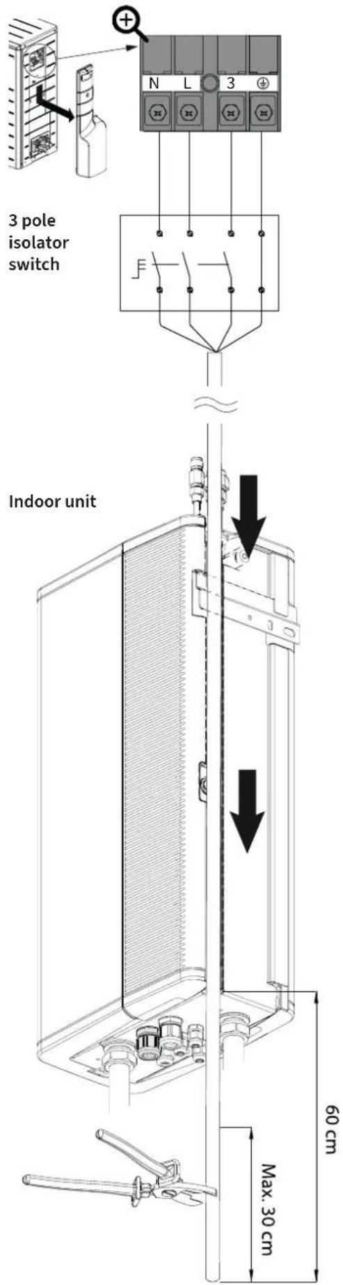
- Cut the (N), (L) and (3*) wires to length noting that the (wire must be 4 cm longer; see diagram (A).
- Remove 1 cm of insulation from all the wires.
- Connect the wires to the terminal strip X1 and Earth to X0 on the indoor unit; see diagram (B).
(3+) = Switched live supply from the indoor to outdoor unit.

8.8.2 Connector plug information

IMPORTANT
For electrical safety please ensure the supplied green connector plugs are fitted correctly to X13 and X2 even if they are not to be used.
- Isolate the power to the indoor unit by switching off the fused spur and removing the 10amp fuse.
- The included 5- and 6-pole plug-in connectors must be attached to the power connectors; see (A) and (B) in the adjacent illustration.
- Use the cable tray on the housing of the printed circuit board to guide the external wiring to the relevant connector(s), see (C).

8.8.3 Wiring the boiler to the indoor unit
For the most efficient operation, the indoor unit should be connected to a boiler that supports OpenTherm communication. Standard on/off potential free switching is also possible.
1. Connecting an OpenTherm boiler.
Using the included 6-pole green connector, wire the boiler OpenTherm connections to screw terminals 1 and 2 and then push this into position X2 of the indoor unit, as shown in the adjacent illustration (1).
(The OpenTherm connections are not polarity specific)
Additional info for boiler settings via OpenTherm:
▶ Set the maximum target temperature of the boiler to 80° C.
If underfloor heating is used, with no mixing valve then set the maximum target temperature of the boiler 20°C higher than the maximum target temperature of the Xtend (see §11.6 (P120 and P194).
▶ Set the boiler maximum output to calculated heat loss required (for example: 10kW)
▶ Set both the minimum and maximum pump capacity of the boiler to 50%.
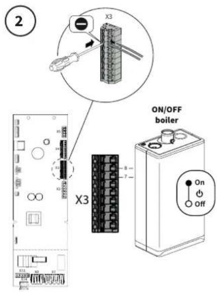
2. Connecting an ON/OFF boiler.
Using the 9-pole green connector X3 wire the boiler ON/OFF connections to the push tabs 7 and 8 of the indoor unit, as shown in the adjacent illustration (2).
The connection must be potential-free failure to comply will result in irreparable damage being caused.
When doing this set P066 to '4' (ON/OFF control) and P121 to '3' (Relay output). See §11.6.
Additional info for boiler settings via ON/OFF:
▶ Set the maximum target temperature of the boiler 10°C higher than the maximum target temperature of the Xtend see §11.6. (P194).
▶ Set the boiler maximum output to calculated heat loss required (for example: 10kW)
▶ Set both the minimum and maximum pump capacity of the boiler to 50%.
8.8.4 Wiring the indoor unit to an existing boiler
Connecting the wires to the correct boiler terminals depends on the make and model of the boiler that the hybrid system is being combined with.
- Remove the original thermostat wiring from the existing combination boiler.
- Now connect the indoor unit wiring to the resulting connection within the boiler. (previously the thermostat; see point 1 or point 2)
- If necessary, consult the installation instructions for the boiler in question.

NOTES
When removing the wiring from the OpenTherm or ON/OFF thermostat terminals within the boiler you then create a pathway for the indoor unit connections.
(ON/OFF boiler connections must be potential-free)

8.8.5 Connecting the room thermostat to the indoor unit
Using the indoor units OpenTherm connection X2 allows any modulating OpenTherm thermostat to communicate in accordance with the OpenTherm communication protocol.
The key function of the OpenTherm thermostat is to calculate the output and flow temperature required for the desired room temperature in order to achieve maximum efficiency.
The OpenTherm room thermostat becomes master and the indoor unit becomes the slave.
With the OpenTherm thermostat:
▶ the current room temperature is displayed.
▶ the required room temperature can be adjusted and set.
If the existing system is equipped with an OpenTherm or ON/OFF thermostat, this must be removed from the boiler connector; see §8.8.3 and §8.8.4.
Option 1 (preferred)
1. Connecting an OpenTherm room thermostat.
Using the included 6-pole green connector, wire the boiler OpenTherm connections to screw terminals 5 and 6 and then push this into position X2 of the indoor unit, as shown in the adjacent illustration (1).
(The OpenTherm connections are not polarity specific)

Option 2
2. Connecting an ON/OFF room thermostat.
Using the included 6-pole green connector, wire the boiler ON/OFF connections to screw terminals 5 and 6 and then push this into position X2 of the indoor unit, as shown in the adjacent illustration (2).
The connection must be potential-free failure to comply will result in irreparable damage being caused.
Choose option "ON/OFF thermostat (with hysteresis) or "ON/OFF thermostat (proportional)" via the installation web-ui wizard or set parameter P064 to "1".
Set parameter P107 to the desired value and make sure it is not set to "0".
For thermostats with hysteresis:
Set parameter P187 to "0".
For proportional band thermostats:
Set parameter P187 to the number of operations per hour. (e.g. 6x per hour, depending on the type of thermostat)
In order to ensure optimal performance and efficiency, only use Intergas Comfort Touch thermostats that were manufactured after September 2022.
These are available under article numbers:
• White; art. no. 030104
• Black; art. no. 030114


8.8.6 Wiring the outdoor sensor to the indoor unit (optional)

NOTES
▶ If the hybrid system is controlled based on a heating curve, it is important for the external sensor T42 to be connected.
▶ Please note: The external sensor is not part of the standard package and is available as a set. Article number: 090064
The 2 x 0.8 mm 2 cable for the external sensor is not part of the standard package.
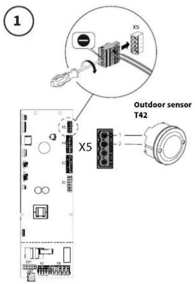
1. Connecting the outdoor sensor T42
Using the 4-pole green connector, included with the kit, wire the connections to screw terminals 1 and 2 and then push this into position X5 of the indoor unit, as shown in the adjacent illustration (1).
Set Parameter P006 to '1'.
For optimal function of the external sensor:
▶ Do not place it in the sun (preferably it should face North) or North-West;
Do not place it where it may be influenced by other heat sources, for example near an external extraction vent or boiler flue terminal.
When it is not possible to install the external sensor, the system can function without it, by setting parameter P006 to '0'.
8.8.7 Wiring a T43 NTC temperature sensor to the indoor unit (optional)

NOTES
If the hybrid system is controlled based on a heating curve or is connected to an ON/OFF boiler (see §11.5, it is important for the external temperature sensor T43 to be connected.
▶ Please note: The temperature sensor is not part of the standard package and is available as a set. Article number: 090064
▶ Always use the included NTC sensor and cable to ensure correct operation of the system.
2. Connecting the external temperature sensor T43.
Using the 4-pole green connector, included with the kit, wire the connections to screw terminals 3 and 4 and then push this into position X5 of the indoor unit, as shown in the adjacent illustration (2).
Set Parameter P123 to '1'.

The temperature sensor T43 must be clipped to the heating flow under the low loss header.
Ensure that the sensor is firmly attached, so that it is in good contact with the pipework at all times.
To ensure the correct operation of the system, the original supplied cables and temperature sensors supplied by Intergas must be used. Place the cables in a suitable duct or conduit to prevent damage.

8.8.8 Installing and using the Comfort Touch room thermostat
Installation
▶ Isolate the indoor unit from the mains power and remove the fuse.
▶ Determine the best internal location ensuring:
- it is not mounted on an exterior wall
- it is not subject to any draughts
- it is not in direct sunlight
- it is not above any type of heat source
▶ Please read the supplied installation manual supplied with the room thermostat, it should be mounted at a height of approximately
1.5 metres from the floor surface. The back plate can be directly attached to a single wall pattres / back box if required using the supplied M3 bolts.
▶ Connect the wires to the terminal block within the thermostat. The wires push 'click' into place.
▶ Place the thermostat body over the top of the back panel and then hinge it down.
▶ Click the housing into place at the bottom.
▶ Replace the fuse and reestablish the power to the indoor unit.
The thermostat will start up automatically.

NOTES
▶ Please read the user instructions to operate the Intergas Comfort Touch.
8.8.9 Comfort Touch app
To enable remote management, the indoor unit must be paired with the Intergas Gateway.
This consists of a LAN2RF gateway and connection equipment. The Intergas Gateway connects the appliance to an internet router, after which an installer can monitor and manage the appliance remotely (via a web server) using the Service Dashboard. The end user must first give permission to the installer to do so, after the installer has invited the end user to the Service Dashboard.
When the Intergas Gateway is used, the end user can also use the Comfort Touch app, which is a thermostat app. The Comfort Touch app can be downloaded from both the Google Play Store and the Apple Appstore.
For setting up the Comfort Touch app and a more detailed description of the app, visit this link: https://www.intergasheating.co.uk/homeowner/products/comfort-touch-app/



8.8.10 Connecting a secondary pump

WARNING
▶ A permanent mains voltage is present at pin 3 of connector X13
Connector X13 is an additional 230V\~ normally open (NO)-contact and can be used for connecting a secondary pump, valve etc.
Use AUX1 to connect a secondary pump:
▶ Using the included 5-pole green connector, wire the pump connections to screw terminals 4 and 5 and then push this into position X13 of the indoor unit, as shown in the adjacent illustration.
▶ Earth to terminal X0.
▶ Set Parameter P068 to "10".
Use AUX2 as an additional (NO)-contact:
▶ Using the included 5-pole green connector, wire the pump connections to screw terminals 1 and 2 and then push this into position X13
Earth to terminal X0.
▶ Set Parameter P069 to the desired value.
See §11.6 Parameters for a full value list for P068 and P069.

9.1 Preparatorywork
▶ Using the diagram "Installation overview" §8.1 ensure the pipework is connected and phased correctly.
▶ Using the diagram "Electrical diagram indoor unit" §8.7.3 Ensure the wiring is connected correctly to each unit or component.
9.2 Filling, cleaning and venting the central heating system
9.2.1 Cleaning and flushing the central heating system
When filling new systems, it is important to remove all residue such as oil, flux solder etc:
▶ Chemically clean the system thoroughly as per BS 7593:2019 Intergas Heating recommend Fernox F3 cleaner is used.
Thoroughly flush the system and treat with the recommended dose levels of Inhibitor: Intergas Heating recommend Fernox F1 combined with Fernox F7 Biocide for low temperature or underfloor systems.
▶ A magnetic system filter must be installed as per BS 7593:2019 positioned in the return pipework to the indoor unit §8.4.1
When filling existing systems, it is important to remove magnetite and corrosion debris:
▶ Chemically clean the system thoroughly as per BS 7593:2019 Intergas Heating recommend Fernox F3 cleaner is used or F8 where heavily contaminated.
Thoroughly flush the system and treat with the recommended dose levels of Inhibitor: Intergas Heating recommend Fernox F1 combined with Fernox F7 Biocide for low temperature or underfloor systems.
▶ A magnetic system filter must be installed as per BS 7593:2019 positioned in the return pipework to the indoor unit §8.4.1
9.2.2 Filling and venting the central heating system
Using the filling valve under or near the boiler, fill the system to a pressure of 1.5bar, then purge the air out via all vent points within the system. Check the system pressure and top-up where required.
- Ensure that the heating system pressure can be read, this will only be possible, in most cases, when the power is switched on to the boiler but it is left in standby (small (--) on the display.
- All isolation valves including radiator lockshields must be open.
- Open the fill valve on the heating return side.
- Slowly open the fill valve on the cold water inlet side until the system pressure is approximately 1.5bar when cold.
- Vent the system using the manual vent on top of the indoor unit (dry any water spills); see (A).
- Vent the boiler using the manual vent on top of the boiler casing (dry any water spills); see (B).
- Vent all the radiators or underfloor manifolds within the heating system; see (C).
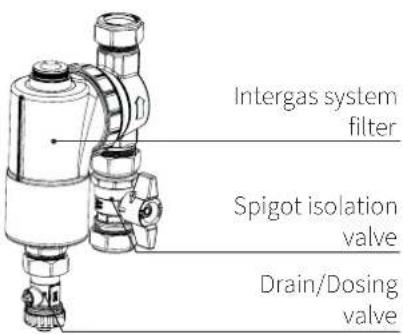

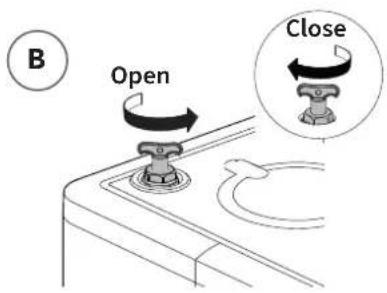

- Check the system for any leaks, rectify where required.
- Top-up the system pressure when required due to venting.
- Close off both filling valves after check the correct pressure has been established.
- Power up the indoor unit and boiler.
- Switch the isolator for the outdoor unit to on.
9.2.3 Checking the heating circuit

NOTES
▶ Check the pressure (1.5 to 2 bar)
▶ Check the inhibitor levels within the heating system
▶ Check the water-side connections to ensure they are leak-tight.
▶ Check if the system has been correctly vented.
▶ Check the system filter for debris and clean if required.
▶ Check all system valves, including the boiler isolation valves, radiator lockshield & TRV's etc. are open.
9.3 Configuration procedure

NOTES
The hybrid heating system must be commissioned by a qualified installer.
To configure and commission the system correctly it is best to use the Web-Ui facility to connect with the Xtend indoor unit control screen (via Wi-Fi), this will walk you through the configuration. process see §10.2.
After the preparatory work has been carried out and completed, the hybrid heat pump system can be configured by following the below procedure:

| Commissioning procedure Notes | |||
| 1 | Insert the fuse into the spur and switch on the power. | The multicolour LED will turn white and flash on & off. | |
| 2 | Press the control button on the indoor unit for 2 seconds to initiate the venting program. | The multicolour LED will turn green and flash on & off indicating that an internal action is being performed.The pump will start running. During this process, make sure that the manual air vents on top of the indoor unit, the boiler and the radiators are correctly vented.1. If the system detects a stable flow, the venting program will end. The multicolour LED will turn white and remain continuously lit.2. If the flow is too low, the LED will turn red. (Notification n023 will appear, see §12.2.) Reset the and repeat step 2. | |
| 3 | Repeat the venting/filling steps if nessesary. | It is important for the venting program to run its entire course. | |
| 4 | Connect to the Xtend Wi-Fi control screen. See the connectivity procedure §10.2. | ||
| 5 | Enter service code 15 and go through the installation wizard to complete the configuration. | If the wizard is not completed, it will reappear when a new connection is made to the operating screen. The installation wizard can also be accessed via the service menu. | |
| 6 | Test the system operation by turning up the room thermostat to create a heating demand. | Use the statistics page to check if the system is functioning well. Menu > Service > View statistics > Live data. §11.2.5. | |
| 7 | Check if there are any notifications or faults present and resolve them as required. | Notification or fault codes are displayed on the main page of the control screen.See chapter 12 for all fault/notification codes. | |
| 8 | Instruct the end user on how to fill, vent and operate the complete system. | ||
| 9 | Give the operating instructions and warranty card "for the customer" to the end user. The completed warranty card must be recieved by Intergas Heating Ltd within 30 days of the installation being finished. Any Intergas system filter being used must also be registered with Intergas at the same time as the Xtend indoor and outdoor units, (for enhanced warranty package). |  | |
10 OPERATION AND READOUT
10.1 Multicolour LED description
The following colours will apply:
Primary colors:
▶ White (short flash) = Device is turned off
▶ White (continuous) = Device is in stand-by mode (Device on, but with no external demand).
▶ Green (continuous) = Device is heating (A heating demand is present).
▶ Green (flashing) = Internal action in progress.
▶ Red (continuous) = Notification active (Device requires attention, but is still functioning). §12.2
▶ Red (fast flashing) = Internal. (Contact Intergas Heating Ltd).
▶ Red (flashing) = Critical/blocking error (Device running emergency program using the boiler) §12
Secondary color:
▶ Purple (fast flashing) = Searching for an Intergas Gateway for up to 5 seconds.
▶ Purple (flashing) = Wi-Fi access point active or a connection to a smartphone or tablet has been established.
The purple colour can be alternated with one of the primary colours above. (for example: purple/green = answers a heat demand and the WiFi module is active)
10.2 Connectivity procedure WiFi control screen
Follow one of the procedures below to connect to the WiFi control screen:
▶ Quick guide (quick connection via QR-codes), see §10.2.1
▶ Manual connection, see §10.2.2
10.2.1 Quick guide (quick connection via QR-codes)
-
Activate the WiFi access point on the Xtend by briefly pressing the LED button on the front of the device. The LED will flash purple.
-
Scan the 1st QR-code A sticker on the front of the device or in point (2) of the WiFi instruction card supplied with the unit. A WiFi connection is now established with the Xtend.
NOTE: this 1st QR-code is unique and must not be destroyed!
- Scan the 2nd QR-code as shown on the right or on the Wifi activation card (point 3). (This makes it easy to open the web browser, with direct access to the WiFi control screen.


10.2.2 Manual connection
- Activate the WiFi access point on the Xtend by briefly pressing the LED button on the front of the device. The LED will flash purple.
- Go to the WiFi settings on the smartphone, tablet or laptop and search for the network "Xtend_
", for example Xtend_2209z01234. - Select network Xtend and enter the password which can be read on the QR code sticker under WPA2 (on the front of the device or in point (2) of the WiFi activation card)
- Open a web browser on the smartphone, tablet or laptop.
- Enter "mydevice.intergasheating.co.uk" as URL in the search bar of the web browser and press "go/enter". If the page of "mydevice.intergasheating.co.uk" is not available, type "10.20.30.1" and press "go/enter".
You can now access the WiFi control screen.
The LED will flash for 15 minutes. As soon as the LED stops flashing, the WiFi connection will no longer be active.

10.3 Wi-Fi control screen description
The Wi-Fi control screen has been designed for both the end user (resident) and the installer. Using a local web server, the current data from the hybrid heat pump system, such as the energy consumption, notifications and malfunctions, can be exported and viewed. Settings (parameters) can be controlled and managed via the control screen. The following menus are available:
▶ Overview
▶ Connections
▶ Settings
Service

10.3.1 Overview (main page)
- Malfunctions are presented via fault codes. These are displayed at the top of the page. The 'reset' button provides the option to reset* a fault code.
- Notifications and fault codes are shown at the top of the page as well. The system will attempt to resolve notifications on its own. If a notification persists, other options will have to be considered.
- The most important statuses and statistics regarding the hybrid heat pump system are shown here.
* A fault code indicates an issue that may not always be resolved without a qualified engineers intervention.
10.3.2 Connections
- This menu provides an overview of all the related devices that are connected. You can also connect to the Intergas Gateway here (if available). The LED will flash fast for 5 seconds.
10.3.3 Settings (for the end user as well as the installer)
- For setting and adjusting daily programs.
- For setting and adjusting the desired Hybrid mode.
- For setting and adjusting the time and date.
10.3.4 Service (specifically for installer)
- Installation wizard for system configuration.
- Tools for use during work or maintenance
- Parameters for making system adjustments.
- Statistics for consulting live data.
- Firmware (update), if available.
Various (parameter) settings on the Wi-Fi control screen are used to influence how the system functions.
Some of these settings can be changed by the end user as well as the installer. Other settings can only be changed within the service menu using the service code 15; see §11.2.1.
The following menus on the Wi-Fi control screen are important for this:
▶ Settings
▶ Service (specifically for the installer)
11.1 Settings (Wi-Fi control screen)
11.1.1 Discription day programs
▶ Silent Mode
▶ Heat pump blockage
Silent Mode

▶ Use this function only when there is a noise issue (i.e. night time operation).
▶ Observe local noise level regulations.
The Silent Mode can lead to less comfort and/or higher energy costs.
The system is equipped with an option to operate in Silent mode (e.g. during the night). This mode can be activated/deactivated using the parameter P172. When this mode is activated, the speed (rpm) of both the compressor and the fan is adjusted to reduce the noise level of the outdoor unit. Set the parameter P167 to the desired capacity reduction (compressor reduction percentage).
By following the steps below, 2 time periods (1 to 2 and 3 to 4) can be programmed on the control screen for when Silent mode is active.
This mode is automatically deactivated when the outdoor temperature is too low. This is done to ensure that the system will still operate at the capacity required to heat the residence or avoid an excessive drop in temperature as a result of Silent mode operation. The minimum external temperature before Silent mode is deactivated can be set using the parameter P171.
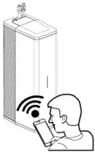
Setting Silent mode:
In this example, Silent mode is set by using a time period From 23:00 to 07:00. During this time period, the noise level of the outdoor unit will be reduced. Silent mode always requires an 'On' and 'Off' time period.
- Go to 'Settings' on the Wi-Fi control screen.
- Select'editprograms'.
- Select 'Silent mode'.
- Edit a time period by clicking on the 'edit' icon, or add a time.
- Select a time. Use the arrows to set the desired time (e.g. 23:00).
- Select an action ('On').
- Click on 'change'.
- Select a second time period.
- Select a time. Use the arrows to set the desired time (e.g. 07:00).
- Select an action ('Off').
- Click on 'Close' to leave the program.
- The settings have been saved.
Heat pump blockage Mode
Using a separate day program (independent of Silent mode), the heat pump can be blocked for a period of time. Using P128, this timed program can be activated or deactivated:
'0' = Timed program off; heat pump not blocked '1' = Timed program on; heat pump blocked
Setting the heat pump blockage:
In this example, the heat pump blocker time program is set by using a time period (00:00 to 06:00). During this time period, the heat pump will be deactivated. All demands for heat will then be forwarded to the boiler.
The heat pump blocker program always requires an ‘On’ and ‘Off’ time period.
- Go to 'Settings' on the Wi-Fi control screen.
- Select'editprograms'.
- Select 'Heat pump blocker'.
- Edit a time period by clicking on the 'edit' icon, or add a time.
- Select a time. Use the arrows to set the desired time (e.g. 00:00).
- Select an action ('On').
- Click on 'change'.
- Select a second time period.
- Select a time. Use the arrows to set the desired time (e.g. 06:00).
- Select an action ('Off').
- Click on 'Close' to leave the program.
- The settings have been saved.
11.1.2 Time settings
- Use the arrows to set the desired time and day, or select 'current time' to import the time and day from your smartphone or tablet.
- Click 'Save the time'.
11.1.3 Hybrid mode

▶ Please note: The hybrid mode can be further adjusted by changing the parameters in the service menu; see §11.2.4. and §11.6
For setting the desired Hybrid mode. The front panel is removed as follows:
- Select one of the desired modes.
▶ Standard COP setting
▶ Ecological (based on CO 2 emission)
▶ Economical (based on rates)
-
Use the arrows to set the desired value.
-
Press 'Save'.
11.2 Service menu (specifically for the installer)
11.2.1 Access to the service menu
- Select the service menu.
- Enter service code 15.
- Click on 'confirm'.
- The menu will now be available.
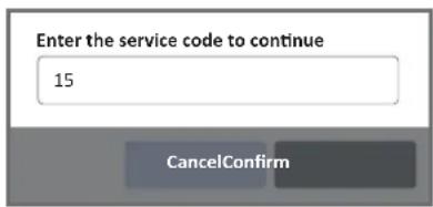
11.2.2 Installation wizard

NOTES
The installation wizard takes several minutes and can be accessed at any time via the service menu.
The installation wizard has been specifically designed to assist in commissioning and configuring the parameters.
The wizard will start on its own when you connect to the Wi-Fi control screen for the first time.
- Connect to the Wi-Fi control screen.
- Enter the service code.
- Follow the installation wizard instructions.
11.2.3 Tools
The following tool functions can be used to commission other system elements or if work or maintenance is required on the system. There is a 'start' and 'stop' button for all programs.
▶ Pump venting
During this program, the pump will operate slowly and stop at brief intervals, so that any air within the system can easily be vented. This process will repeat itself until the system detects a stable flow. During this process, please ensure that the manual air vents on top of the indoor unit, the boiler and the radiators are correctly vented, (§9.3 - point 2)
▶ Activating the system pump
During this program, the pump will operate continuously. Use the arrows to set the desired flow rate (l/min).
▶ Manual defrosting
During this program, the heat pump evaporator will be defrosted.
▶ Heat pump service mode (minimum)
During this program, the pump will operate at minimum output.
▶ Heat pump service mode (maximum)
During this program, the pump will operate at maximum output.
▶ Boiler service mode
During this program, the boiler will be activated.
▶ Pumping out refrigerant
The pump draining function can be used to commission the system, such as by emptying the meter set, for maintenance work or decommissioning the system. During this process, the refrigerant will be moved back into the outdoor unit, §8.6.8
11.2.4 Parameters (adjustment)
The search function on the WiFi control screen can be used to find a parameter. Parameter settings must always be saved using the 'Save' button.
The complete parameter list is explained in §11.6.
11.2.5 Statistics
The statistics page provides a complete overview of the system's energy consumption. This page can also be used to monitor the system.
Select 'Live data' to review the current system data.
11.2.6 Firmware (update)
Consult Intergas Heating Ltd.
11.3 Adjusting the hybrid work mode
The hybrid system consists of heat pump (ODU = outdoor unit), the boiler (B) and the indoor unit (IDU). The 3 units work together to optimise efficiency based upon the catagories that are input and the average COP (coefficient of performance), using the lowest possible cost price and/or CO₂ emission.
There are three categories for space heating:
- Heat pump only
- Heat pump + boiler assistance
- Boiler only
Using P102, the external temperature can be set to a value above which the boiler is prevented from being activated. By lowering this value, the system is forced to operate the heat pump for longer without involving the boiler.
Using P103, the system can be forced to switch over to the boiler, even if the heat pump COP is still above the COP threshold value.
- Typically, the heat pump is used for as long as possible.
- If the heat pump cannot achieve the desired heat level (within the set time frame), the boiler will assist the heat recovery process.
- Switching to the boiler will only occur if:
• There is a heat pump malfunction.
- The heat pump is unable to achieve the requested target temperature.
- The average COP is lower than the current COP threshold value P101.
- The external temperature is below the value set for P103.
- The current return temperature is higher than the value set for P104.


ODU (Outdoor unit)
+

B (Combination boiler)
+
IDU (Indoor unit)
11.3.1 Setting the hybrid mode
The P100 parameter can be used to influence how the boiler and heat pump interact. This is also called bivalent mode. The following settings are possible: P100:
0 = Entirely electric (boiler not activated).
In this mode, the boiler is not activated, not even when defrosting.
1 = Standard COP setting
If the heat pump is set below a specific COP, this mode switches over to the boiler. The lower the COP set, the longer the heat pump will run. The COP threshold value can be set using P101. The standard value is 2.0. Operation is not affected by the rate settings (as in point 3).
2 = Ecological (based on CO₂ emission)
Using P143, the CO2 emission for kWh of electricity is set (grams of CO2 per kWh). This value is weighted against the CO2 emission from natural gas. This emission value can be found in your energy bill or from your energy supplier.
3 = Economical (based on rates)
In this mode, the COP threshold is determined based on the gas and electricity rates. A low and high rate can be provided for electricity:
▶ P140: High electricity rate (£ sterling per kWh)
▶ P142: Low electricity rate (£ sterling per kWh)
▶ P144: Natural gas rate (£ sterling per m 3 )
4 = Maximum heat pump use
In this mode, the heat pump is used as much as possible, however the boiler can be activated as well but only if the heat pump cannot achieve the required target temperature.
5 = Only the boiler
If there are issues with the heat pump, the system can be forced to use the boiler.
11.4 Settings for activating the boiler
Activating the boiler is determined based on the water temperature and room temperature (using OpenTherm if available).
Generally, this setting works using degree minutes. This means that a significant deviation in water temperature leads to the involvement of the boiler sooner than a minor deviation.
Using P107, the activation threshold can be set. At a lower value, the boiler will be involved more quickly.
Heat pump malfunction
If the heat pump is unavailable due to a malfunction, the boiler will be activated directly to meet the heating demand. The delay time can be set using P108.
Delay time before the involvement of the boiler after initiating heating
When the heating phase is initiated, the involvement of the boiler can be postponed in order to allow the heat pump time to achieve the desired heat on its own. A wait time that depends on the external temperature can be set for this. In relatively warm weather, the wait time can be extended.
Using P113, a minimum external temperature can be set (the default is 0 °C).
Using P114, a maximum external temperature can be set (the default is 20 °C).
Using P115, the wait time can be set for a low external temperature (the default is 5 min).
Using P116, the wait time can be set for a high external temperature (the default is 50 min).

11.4.1 Setting a reduced temperature
During a period in the daytime, boiler involvement can be postponed, which will result in a lower room temperature. This ‘reduced temperature’ can based on a ‘reduced room temperature setpoint’ or a timed program.
Reduced temperature setpoint.
Using P218, a temperature setpoint can be set. If the room temperature setpoint is actually set to be equal to or lower than this value, the reduced temperature function will activate.
When the reduced temperature function is active, the boiler is prevented from being involved. This allows the room temperature to drop below the setpoint. A maximum drop in temperature can be set using P219. If the current room temperature drops below the thermostat value (— negative)
P219 — then the boiler becomes free to activate.
The reduced temperature function via a room temperature setpoint can be deactivated by setting P218 to '10°C' §11.4.1
This function is intended for situations when the night-time reduction is being used (P180 = 0).
In situations where the same room temperature has been set 24/7, the CH timed program can be used to indicate when the boiler should be blocked. For the period of the 'CH mode OFF' timed program, the reduced temperature function will be active.
At lower external temperatures, this function may have the opposite effect: the room temperature will drop too much, even though it is no longer possible to compensate for it. Using P216, a 'reduced temperature off' temperature can be set.
11.5 Room heating settings (CH mode)
The hybrid system is controlled using the Intergas Comfort Touch thermostat or any OpenTherm thermostat. Parameter P202 is set to '4', the default value for the this type of thermostat.
There are several other control modes available in addition to the factory settings, which can even be combined with each other. These are divided into internal and external control modes.
Internal control modes are based on the supply temperature. The system uses a weather-dependent control (WDC) setting that adjusts based on the external temperature and the set heating curve.
Optional accessories, such as the external sensor T42 (outdoor) and remote temperature sensor T43 (system flow), are important for optimal system performance.
External control modes use an external thermostat to determine the supply temperature. There are also ON/OFF CH modes. These fall under the external control modes.
If these are being used for a different application (different from the default value), further information can be requested from Intergas Heating Ltd.
11.6 Parameter list
The parameters are set at the factory in accordance with the table below. These parameters can only be changed using the service code. Please note: Installers must be fully versant with the below parameters, incorrect adjustment or setting can damage the equipment.
| Parameter | Category Setting | Default value | Description/Setting range | |
| PO00P000 | General Device in use. 1 | 0 = no1 = yes | ||
| PO04P004 | Connections | Room heating connected to the system | 1 | 0 = no1 = yes |
| PO06P005 | Connections External outdoor sensor connected. 0 | 0 = no1 = yes | ||
| PO07P007 | Connections Source of the external temperature. 0 | 0 = automatic. (external sensor, internet, outdoor unit sensor)1 = external outdoor sensor T42 (P006 = 1)2 = internet3 = outdoor unit sensor4 = CH-Boiler (via OpenTherm) | ||
| PO08P009 | Connections not applicable - deactivated | |||
| PO10P010 | Connections not applicable - deactivated | |||
| P011 | Connections not applicable - deactivated | |||
| P015 | Calibration | External outdoor sensor T42. | 0.0 | -12.7 °C to 12.7 °C (increments of 0.1) |
| P016P015 | Calibration | Return sensor T04. | 0.0 | -12.7 °C to 12.7 °C (increments of 0.1) |
| P017 | Calibration | Flow sensor T03. | auto | -12.7 °C to 12.7 °C, auto |
| P018P018 | Calibration | External temperature flow sensor T43. | auto | -12.7 °C to 12.7 °C, auto |
| P020P020 | Connections | Setting minimum CH pressure threshold value | 0.5 | 0.0 to 4.0 bar (increments of 0.1 bar). |
| P021 | Connections | Use of the OpenTherm pressure sensor in the existing boiler. | 1 | 0 = Does NOT use the OpenTherm pressure sensor1 = DOES use the OpenTherm pressure sensor |
| P024P024 | Connections | Heating demand input type through Connector X2 (contacts 5 and 6) | 1 | 0 = deactivated (Opentherm default)1 = ON/OFF based on heating demand |
| P025P025 | Connections | Heating demand input type through Connector X2 (contacts 3 and 4) | -deactivated | |
| P026P026Parameter | ConnectionsCategory Setting | Function of digital output 1 relay (Connector X3, contacts 7, 8 and 9) | 0Default value Description/Setting range | 0 = not in use1 = signal, cooling active2 = signal, heating active3 = control of the secondary CH pump4 = Hybrid boiler ON/OFF5 = indoor unit on (P000 = 1)6 = secondary pump (even during defrosting)7 = locked status8 = locked/notification status9 = heat pump malfunction10 = Sec. pump (active during heat pump and boiler) |
| POSTP087 | Connections | Function of digital output 2 relay (Connector X4, contacts 1, 2 and 3) | 0 | 0 = not in use1 = signal, cooling active2 = signal, heating active3 = control of the secondary CH pump4 = Hybrid boiler ON/OFF5 = indoor unit on (P000 = 1)6 = secondary pump (even during defrosting)7 = locked status8 = locked/notification status9 = heat pump malfunction10 = Sec. pump (active during heat pump and boiler) |
| POSSP088 | Connections | Function of AUX 1 relay (Connector X13, contacts 4 and 5) | 0 | 0 = not in use1 = signal, cooling active2 = signal, heating active3 = control of the secondary CH pump4 = Hybrid boiler ON/OFF5 = indoor unit on (P000 = 1)6 = secondary pump (even during defrosting)7 = locked status8 = locked/notification status9 = heat pump malfunction10 = Sec. pump (active during heat pump and boiler) |
| POSSP089 | Connections | Function of AUX 2 relay (Connector X13, contacts 1 and 2) | 0 | 0 = not in use1 = signal, cooling active2 = signal, heating active3 = control of the secondary CH pump4 = Hybrid boiler ON/OFF5 = indoor unit on (P000 = 1)6 = secondary pump (even during defrosting)7 = locked status8 = locked/notification status9 = heat pump malfunction10 = Sec. pump (active during heat pump and boiler) |
| POSTP081 | System | Setting IDU pump output (maximum pump control). | 100 20 to 100% | |
| POSSP086 | System | Minimum ΔT for heating. Reduces flow rate when ΔT falls below set value. | 0 | 0 = off (always uses the set flow rate)1 to 15 |
| POSSP088 | System (IDU) | Pump mode 0 | 0 = standard pump control1 = pump is operating continuously while in stand-by2 = pump is always operating (emergency program) | |
| P100P100 | Bivalent | Setting hybrid/bivalent operation mode | 1 | 0 = entirely electric1 = minimum COP (P101)2 = ecological (based on CO2 emission)3 = economical (based on rates)4 = maximum heat pump use5 = only the boiler (no heat pump) |
| P101P101 | Bivalent | Setting minimum COP for heat pump operation | 2.0 1.0 to 10.0 (increments of 0.1) | |
| P102P102 | Bivalent | Setting the external temperature value (Boiler will not be involved in heating above this value). | 15 °C -20 °C to 20 °C (increments of 1 °C). | |
| Parameter | Category Setting | Default value Description/Setting range | ||
| PI03P103 | Bivalent | Setting the external temperature value. (No heat pump operation below this external temperature value). | -5 °C -20 °C to 20 °C (increments of 1 °C). | |
| PI04P104 | Bivalent | Setting return sensor value. (No heat pump operation above this CH value). | 50 °C 25 °C to 55 °C (increments of 1 °C). | |
| PI05P107 | Bivalent | Delay in involvement of the boiler (at a lower value, the boiler will be involved more quickly). | 0 | 0 = adaptive mode (adjusts itself)1> = 40 to 8000 degree minutes. |
| PI06P108 | Bivalent | Setting the delay for the involvement of the boiler if the heat pump is experiencing a malfunction. | 0 0 to 250 min. | |
| PI09P109 | Bivalent Setting the minimum boiler off-time 1 1 to 60 min. | |||
| PI13P113 | Bivalent | Setting the minimum external temperature (for the involvement of the boiler). See §11.4 | 0 °C -20 °C to 30 °C. | |
| PI14P114 | Bivalent | Setting the maximum external temperature (for the involvement of the boiler). See §11.4 | 20 °C -20 °C to 30 °C. | |
| PI15P115 | Bivalent | Setting the wait time for the boiler at a low external temperature. See §11.4 | 5 0 to 250 min. | |
| PI16P116 | Bivalent | Setting the wait time for the boiler at a high external temperature. See §11.4 | 50 | 0 to 250 min. |
| PI17P120 | Bivalent | Setting the maximum requested boiler supply temperature. | 80 °C 30 °C to 90 °C. | |
| PI17P121 | Bivalent Setting a back-up type. | 2 | 0 = none1 = OpenTherm connector X2 (contacts 5 and 6, only ON/OFF control)2 = OpenTherm boiler3 = freely adjustable relay outlet | |
| PI17P123 | Connections | External supply temperature sensor T43 connected. | 0 | 0 = no1 = yes |
| PI17P124 | Bivalent | Setting the threshold value. (Boiler will become involved in heating if the difference in the flow temperature and the requested temperature is too high). | 25 °C 5 °C to 50 °C (increments of 1 °C). | |
| PI17P125 | Bivalent | Setting the time delay of the pump after only the boiler has been operating. | 1 0 to 30 sec. | |
| PI17P126 | Bivalent | Setting the minimum requested boiler flow temperature. | 20 °C 20 °C to 50 °C. | |
| PI17 | Bivalent | Setting the time frame if the boiler is set to low-capacity operation. | 10 | 5 to 60 min. |
| PI20P128 | Bivalent | Activation/deactivation of the heat pump blockage program; see §11.1.1 | 0 | 0 = no, heat pump not blocked1 = yes, heat pump can be blocked |
| PI20P129 | Bivalent | Minimum control percentage of the boiler during on/off operation.(relates to P127) | 10 5% | to 100% |
| PI20P130 | Defrosting | Activating the boiler during defrosting. 1 | 0 = always activate the boiler when defrosting.1 = only activate the boiler below a certain minimum temperature (P131).2 = never activate the boiler. | |
| PI21P131 | Defrosting | Setting minimum supply temperature when defrosting (see P130=1). | 15 °C 5 °C to 30 °C. | |
| PI20P140 | Bivalent | Setting electricity rate per kWh (high rate). | 0 0 to 9999 £/KWh. | |
| PI20P142 | Bivalent | Setting electricity rate per kWh (low or off-peak rate). | 0 0 to 9999 £/KWh. | |
| PI20P144 | Bivalent Setting rate per m3 gas: 0 0 to 9999 £/m3. | |||
| PI20P146 | Bivalent | Setting CO2 emissions in grams per KWh. | 0 0 to 9999 g/KWh. | |
| PI20P165 | Heat pump | Setting degree minutes for heating.This affects when the heat pump starts and stops (a higher value means fewer activation changes). | 0 | 0 = adaptive mode (adjusts itself)1 to 42 degree minutes(increments of 10 degree min.) |
| PI20P167 | Heat pump | Setting compressor reduction percentage during Silent mode(if P172=2) | 50 20 to 100% | |
| PT11P171 | Heat pump | Setting the external temperature value(Silent mode deactivated below this external temperature). | -20 °C -20 °C to 20 °C. | |
| PT22P172 | Heat pump | Activation/deactivation of Silent mode. | 0 | 0 = off1 = on (fixed, non-adjustable reduction of 5 dB)2 = a maximum percentage set by the user (adjustable using P167) |
| PT22P175 | Heat pump | Setting whether the crankcase heater remains hot. | 1 | 0 = never (only when compressor starts)1 = maximum of 24 hours2 = always |
| PT16P178 | Heat pump | This setting determines if or when the boiler will become involved in heating for the crankcase heater. | 1 | 0 = never1 = automatic (delay time determined based on P113, P114, P115 and P116)2 = always |
| P180 | CH comfort Setting the CH timed program. | 0 | 0 = Comfort mode1 = Eco mode | |
| P181 | CH comfort | Setting the difference in room temperature and heating threshold. | 30 °C | to 15 °C. |
| PI83P182 | CH comfort | Setting the maximum that the average room temperature and the set room temperature can be exceeded by. | 21°C to 5°C. | |
| PI83P183 | CH comfort | Setting the pump flow rate if the heating pump is activated l/min). | 15.0 to 25 l/min. | |
| PI83P184 | CH comfort | Setting the pump flow rate if the heating pump is NOT activated l/min). | 6.5 to 25 l/min. | |
| PI83P185 | CH comfort | Setting the threshold value for immediate involvement of the boiler at a timed program setpoint (from 2.2°C) | 2.2 to 5.0°C | |
| PI83P187 | CH comfort | Setting ON/OFF thermostat switches per hour | 0 | 0 = off (no pulsing)1 to 12 = (number of switches per hour) |
| PI83P188 | CH comfort | Setting a base point for a timed program 'ON period' (if there is no setpoint) (see 11.5). | 20°C to 30°C. | |
| PI83P189 | CH comfort | Setting a base point for a timed program 'OFF period' (if there is no setpoint) (see11.5). | 20°C to 30°C. | |
| PI83P190 | CH comfort | Setting a pump flow rate if only the boiler is active (l/min). | 15.0 to 25.0 l/min. | |
| PI83P191 | CH comfort | Activating/deactivating CH clock program. | 0 | 0 = off1 = on |
| PI83P192 | CH comfort Setting heating curve slope 1.10 0.00 to 2.50 (increments of 0.01) | |||
| PI83P194 | CH comfort Setting maximum supply temperature. 70 to 20°C to 85°C. | |||
| PI83P195 | CH comfort Setting proportional constant. | 160 to 255 | ||
| PI83P196 | CH comfort | Setting integrating factor (a lower value yields a quicker response). | 1 to 255 | |
| PI83P197 | CH comfort | Setting a differentiating constant (a higher value yields a quicker response in alternating circumstances). | 0 to 255 | |
| PI83P198 | CH comfort | Setting maximum positive displacement of the heating curve as a result of room heating compensation. | 10°C to 50°C. | |
| PI83P199 | CH comfort | Setting maximum negative displacement of the heating curve as a result of room heating compensation. | 10°C to 50°C. | |
| P200 | CH comfort Setting heating system | 0 | 0 = underfloor heating1 = radiators2 = convectors | |
| P202P202 | CH comfort Setting thermostat control 4 | 0 = Full control by WDC. None thermostat connected.1 = WDC + room temp. compensation control.2 = WDC + room temp. compensation control. + ON/OFF thermostat.3 = WDC + ON/OFF thermostat.4 = Standard OpenTherm thermostat.5 = WDC + ON/OFF thermostat (via OpenTherm or ON/OFF shortcut).6 = Fixed water temperature + ON/OFF thermostat.7 = Internal WDC + external OpenTherm thermostat.8 = WDC + ON/OFF thermostat (proportional band). | ||
| P203P203 | CH comfort Setting thermostat hysteresis. 0.50 0.00 to 2.50 (increments of 0.01) | |||
| P205P206 | CH comfort | Setting nightly reduction and/or daily increase (ΔT); see §11.5 | 1.0 0.0 to 5.0°C (increments of 0.1) | |
| P207P207 | CH comfort | Activating/deactivating room heating modes. | 1 0 = off1 = on | |
| P209P209 | CH comfort | Influencing the thermostat based on the heating curve (if P202 = 7)(0% = no influence). | 50 0 to 100%. | |
| P210P210 | CH comfort Raising/lowering the heating curve. 0 -5 °C to 40 °C. | |||
| P211 | CH comfort Slow-start setting (0 = off). 60 0 to 240 min. | |||
| P214 | CH comfort | Setting the hour of the day that the maximum temperature is reached (if P180=1 Eco mode = ON). | 16 0 to 23 hours. | |
| P215P215 | CH comfort | Setting external temperature.(Deactivates nightly reduction and daily increase at this value). | -10 °C -20 °C to 20 °C. | |
| P217 | CH comfort | Setting a value for immediately switchen the CH-boiler when the room thermostat temperature is set manually (0 = off) | 0,7 0,0 t/m 5,0°C | |
| P218P218 | CH comfort | Defines a "lower temperature". It blocks the CH-boiler if the room temperature deviation is smaller than P219. See §11.4.1 (10 = off) | 10 10 to 20 °C | |
| P219P219 | CH comfort | Setting maximum drop (regarding P218). | 0.5 0.0 to 5.0 °C | |
| P220P220 | CH comfort | Setting the desired compressor 'ON' time (if P202=5). | 90 15 to 240 min. | |
| P221 | CH comfort | Setting maximum deviation as a result of the adaptive ON/OFF control based on the heating curve (if P202=5 or 8). | 3.0 0.0 to 10.0 °C | |
| P255P255 | General | Reset the device to factory settings | 0 0 = off9 = reset to factory settings | |
12.1 Fault codes
If a fault occurs that blocks the heat pump operation, then any heating demand will automatically be forwarded to the boiler. Go to the WiFi control screen to read the fault code generated. Use the reset button in the WiFi control screen or press and hold the button on the indoor unit for 8 seconds to reset the device.
The fault codes are as follows:
| Fault code Description Possible cause/solution | ||
| F001 | No flow in the CH circuit for at least 30 minutes. | ▶ Check the CH pump. ▶ Check the system for leaks. ▶ Check the system water pressure. |
| F003 | Value of external flow sensor T43 too high (>67°C) or Value of flow sensor T03 over 1 minute too high. (>90°C) | ▶ Check the flow in the system. |
| F009 | Memory fault codes. | ▶ Reset the control unit. ▶ Replace the control unit. |
| F010 | Water temperature too low during defrost function. | ▶ CH flow too low. Check system flow. |
| F018 | Heat pump type not correctly configured. | ▶ Consult Intergas Heating Ltd. |
| F019 | Incorrect serial number in memory module. | ▶ Consult Intergas Heating Ltd. |
| F020 | Incorrect firmware. | ▶ Consult Intergas Heating Ltd. |
| F022 | Firmware version not compatible | ▶ Firmware needs an updating. ▶ Consult Intergas Heating Ltd. |
| F023 | XTP controller internal | ▶ Consult Intergas Heating Ltd. |
| F024 | XTP controller configuration | ▶ Consult Intergas Heating Ltd. |
| F025 | XTP controller communication | ▶ Consult Intergas Heating Ltd. |
| F026 | Startup | ▶ Switch off the power at the fused spur for 1 minute, the re-establish. ▶ Replace the control unit. |
| F037 | Return sensor T04. | ▶ Check for any breakages/short circuits in the wiring for the sensor T04. ▶ Check whether the sensor T04 is connected correctly. ▶ Replace the sensor T04. |
| F038 | Flow sensor T03. | ▶ Check for any breakages/short circuits in the wiring for the sensor T03. ▶ Check whether the sensor T03 is connected correctly. ▶ Replace the sensor T03. |
| F039 | External flow sensor T43. | ▶ Check for any breakages/short circuits in the wiring for the sensor T43. ▶ Check whether the sensor T43 is correctly connected. ▶ Replace the sensor T43. |
| F040 | External outdoor sensor T42. | ▶ Check for any breakages/short circuits in the wiring for the sensor T42. ▶ Check whether the sensor T42 is correctly connected. ▶ Replace the sensor T42. |
| F050 | Fault within the outdoor unit | ▶ Access the control screen for additional information |
| F051 | Fault within the indoor unit | ▶ Access the control screen for additional information |
| F254 | Bypass mode active | ▶ Not a fault code as such, but a forced way to forward the heat request to the boiler. ▶ Switch off the power at the fused spur then, press and hold the control button whilst re-establishing the power supply to clear the by-pass mode. |
12.2 Notification codes
In addition to fault codes, the control unit can also display notifications. Notifications are displayed if an anomaly occurs somewhere in the system that does not affect the vital functioning of the system. Notifications disappear if the system can fix the anomaly. Intergas Heating must be consulted if a notification returns repeatedly.
When using a digital type OpenTherm room thermostat notification codes from either the heat pump or the boiler can be displayed on its display screen, otherwise they can be viewed via the WiFi control screen.
Non compatible OpenTherm room stats will display F050 = heat pump error or F051 = CH-boiler error
The following notifications are used:
| Notification | Description Possible cause/solution | |
| n000 | Parameter settings outside range | ▶ Check the settings. |
| n001 | System pressure too low, parameter P020 | ▶ Check for leaks▶ The system water requires refilling or topping up. |
| n008 | XTP error heat pump (ODU) | ▶ Consult Intergas Heating Ltd. |
| n011 | Communication with the outdoor unit has been lost or the outdoor unit has an internal. | ▶ Access the WiFi control screen for additional information▶ Check the wiring between the indoor unit and outdoor unit for breakages/short circuit.▶ Check the connections in the outdoor unit. |
| n013 | Condenser temperature too high: heating pump disengaged. | ▶ Potentially insufficient flow. |
| n014 | Thermostat not connected. | ▶ Connect the Comfort Touch thermostat; see §8.8.5. |
| n015 | Crankcase heater function | ▶ Possible loose connection to the outdoor unit▶ Faulty resistance element. |
| n016 | Abnormal Delta-T between the flow and return temperature values | ▶ Sensors T03 and T04 connected or mounted incorrectly.▶ Check the system flow. |
| n018 | Problem with memory. | ▶ Consult Intergas Heating Ltd. |
| n019 | Fault memory module | ▶ Check the wiring.▶ Replace the memory module. |
| n021 | No flow in the CH circuit for at least 30 seconds. | ▶ Venting program (max. 15 minutes) is started. Other system functions are blocked and resumed after the program has completed.▶ Pump turns off for 60 seconds.▶ Pump runs at maximum capacity.▶ If sufficient flow is regained again for 30 seconds, the program will stop and the notification code will clear. |
| n022 | Problem with automatic flow rate control | ▶ Probably air in the system, vent. |
| n023 | System flow too low during commissioning | ▶ Check the CH-circuit for restrictions, debris, air or isolation valves closed. |
| n039 | Problem with external flow temperature sensor T43 | ▶ Check the position and connection of the sensor on the flow pipework.▶ Check wiring. Replace if necessary. |
| n040 | Problem with external outdoor sensor T42 | ▶ Check wiring. Replace if necessary. |
| n041 | Problem with refrigerant liquid sensor. | ▶ Check wiring. Replace if necessary. |
| n042 | Problem with refrigerant gas sensor. | ▶ Check wiring. Replace if necessary. |
| n051 | Boiler locked out of system ▶ | Check for boiler malfunction. |
| Notification | Description | Possible cause/solution |
| n052 | Error with OpenTherm connection to boiler. | ▶ Check wiring. Replace if necessary. |
| N053 | Flow temperature from boiler is too low | ▶ Set the flow target temperature of the boiler to the same as the maximum flow target temperature of the Xtend or higher (P194). |
| N054 | Boiler not responding to heating request from Xtend. | ▶ Check whether the boiler or CH function is turned off. |
| N055 | Boiler has a notification | ▶ Resolve the boiler malfunction. |
| N060 | Thermostat firmware version is not up to date if using the Intergas Comfort Touch. | ▶ Install the latest version of Intergas Comfort Touch. |
12.3 Other malfunctions
12.3.1 Malfunction within the indoor unit
| Possible causes Solution | |
| The power LED is not displayed. | ▶ Check the supply voltage, 230V AC 50Hz, see §5.3 |
| Thermostat not connected or faulty. ▶ | Check the wiring. ▶ Check the connection between the indoor unit and the thermostat, see §8.8.5 ▶ Replace the thermostat. |
| No power (24V). ▶ Check the fuse. | ▶ Replace faulty parts. ▶ Check the wiring according to the diagram; see §8.7.3. |
12.3.2 CH does not get up to temperature
| Possible causes Solution | |
| Water pressure in system is too low. | ▶ Check system for leaks; top the system up if necessary. |
| Thermostat is not working. | ▶ Check the settings and adjust if necessary. |
| Temperature is set too low. | ▶ Increase the room thermostat target temperature.▶ Flow temperature from boiler is too low, increase the boiler target temperature.▶ Check the external temperature sensor for for a short-circuit, check the parameter settings where necessary, P102, P113, P114, see §11.4. |
| No heat transfer due to dirt or debris in the installation. | ▶ Flush the system to BS 7593:2019, clean the filter add inhibitor, see §9.2.1. |
12.3.3 CH installation stays too hot
| Possible causes Solution | |
| Faulty thermostat. | ▶ Check thermostat for issues; short circuit, batteries where applicable etc, replace thermostat if necessary. |
| Faulty temperature sensor(s). | ▶ Check all temperature sensors; replace faulty sensor |
12.3.4 Malfunction of the outdoor unit
| Possible causes Solution | |
| Outdoor unit does not start up. | ▶ Check the supply voltage, 230V AC 50Hz, see §5.3▶ Check the isolator switch is turned on.▶ Check the switched line powered between the indoor unit and outdoor unit.▶ Check the fuses in the outdoor unit; replace if necessary. |
| Heat output capacity of the outdoor unit is too low. | ▶ Possible ice formation/debris accumulation restricting the evaporator: carefully clean the evaporator or remove the ice/snow see §13.3▶ Check the settings; adjust settings if necessary.▶ Check operation of air intake NTC; replace if necessary.▶ Too little refrigerant in the system: check for leaks and top up the system if necessary (should only be performed by an E-gases certified installer). |
| Low pressure problems at start-up. | ▶ Filter blockage. Replace filter.▶ Check EEV (Electronic expansion valve) cables.▶ Check whether the solonoid on the EEV is faulty.▶ No airflow in heat exchanger; check fan operation; check whether the heat evaporator is clean.▶ Shortage of refrigerant in the system: check for leaks and top up (should only be performed by an E-gas certified installer). |
| Compressor won't start. | ▶ No compressor voltage; check power supply/fuses▶ Check electrical connections.▶ Compressor protection triggered; compressor temperature too high.▶ Check refrigerant fill level. |
| Compressor makes a high-pitched sound | ▶ Fluid refrigerant enters compressor; poor evaporation in system. Find cause and try to resolve it.▶ Faulty compressor; repair compressor. |
| Fan is not operating | ▶ Faulty fan fuse; replace fuse.▶ Faulty fan motor; replace motor.▶ Fan printer circuit board is faulty or internal cables are damaged. |
| The compressor works, but there is no heat output from the heat pump. | ▶ Shortage of refrigerant in the system: check for leaks and top up (should only be performed by an F-gas certified installer).▶ Evaporator faulty; locate and replace if required.▶ Compressor faulty; replace compressor. |

If a fault/notification causes the boiler to operate and take over from the hybrid heat pump system, it can have an adverse effect on the end user's energy consumption.
▶ Replace defective parts with original Intergas parts only.
▶ Failure to install the sensors or installing them incorrectly may result in serious damage.
The entire hybrid heat pump system must be serviced and cleaned on an annual basis by an authorised installer.

CAUTION
When the system has just been operating, certain components may be hot to touch.
13.1 Cleaning the filter
▶ Clean the filter. Proceed as follows:
- Isolate the power to both the CH-boiler and the indoor units.
- Close the boiler isolation valves and filter spigot valve.
- Unscrew the system filter drain valve cap.
- Use the drain valve cap to open the drain valve.
- Unscrew and remove the magnet from the filter.
- Drain the dirty water from the filter into a bucket or hosepipe by slowly opening the spigot valve at the bottom of the filter.
- Close the drain valve again.
- Replace the magnet back into the filter.
- Open the boiler and spigot isolation valves.
- Check the system pressure and if necessary increase to 1.5 to bar.
- Re-establish the power to both the CH-boiler and the indoor units.

▶ Intergas recommend using our own system filter as illustrated. When using a different manufacturers magnetic and hydronic separation filter please refer to their instructions for maintenance and cleaning.

13.2 Indoor unit maintenance work
▶ Check the water pressure in the system through the WiFi control screen, or the boiler display where applicable.
Fill and vent the system if necessary.
• The recommended water pressure is 1.5 to 2 bar.
- If the system requires a top up twice a year or more, check for leaks.
▶ Isolate the indoor unit from the mains power by switching off the fused spur and removing the fuse.
▶ Loosen the screw below the indoor unit and remove the front cover; see §8.3.3.
▶ Ensure all pipework and refrigerant lines have cooled down.
▶ Ensure that all sensors are correctly located and that the wiring is not damaged or disconnected. Repair/replace if necessary.
▶ Ensure there are no water leaks, repair where required.
▶ Replace the front cover and tighten the screw under the device; see §8.3.3.
▶ Clean the outside of the unit with a damp cloth. Do not use aggressive or abrasive cleaning agents or solvents.
▶ Re-establish the power supply by replacing the fuse and switching on the fused spur.
▶ Acquire a readout from the device using the Wi-Fi control screen.
13.3 Outdoor unit maintenance work

CAUTION
If the outdoor unit is not cleaned regularly, this may lead to poor output, freezing, leaks or problems with the compressor.
The evaporator fins are very delicate and have sharp edges. Use safety gloves as a precaution to prevent any injuries.

WARNING
If the outdoor unit is disconnected from power, the electrical circuitry in the outdoor unit will still be live for another 8 to 10 seconds.
For environmental and technical reasons, regular cleaning and maintenance of the outdoor unit is recommended to ensure maximum efficiency and correct operation of the outdoor unit.
▶ Note to see if there is any excess noise or vibration from the outdoor unit due to debris build-up on the fan blades etc.
▶ Isolate the outdoor unit from the power supply by turning the 3 pole isolator switch to off (A).
Remove any dirt, leaves and debris from around the unit.
▶ Check for any damage to the outdoor unit, repair or replace any damaged components.
▶ Check for any damage to the refrigerant pipework insulation, replace any damaged areas and ensure it is sealed from the elements.
Remove the front grill (B) so that the fan and evaporator can be accessed easily. Clean the fan by hand with a damp soft microfibre type cloth (Do not use any solvent type cleaners).
▶ Check the rotation and balance of the fan. If either of these is noticeably poor, the fan blade or motor must be replaced.
▶ Clean the aluminium fins of the evaporator by carefully spraying water onto the back of them. Check the fins for damage as well and repair them if necessary by using a fin alignment comb.
▶ Check for signs of rust or scratching on the coating of the outdoor unit, and repair faulty components or apply rust-resistant paint if required.
▶ Refit the front grill (B) to the outdoor unit and to prevent vibration or noise, ensure it is located correctly and secured with all 6 screws.
▶ Clean the outside of the unit with a damp cloth. Do not use aggressive or abrasive cleaning agents or solvents.
▶ Turn the isolator switch (A) back to on.

Example of 3 pole isolator switch
13.4 Decommissioning the system
Decommissioning can only be completed by an F-Gas qualified and registered engineer.
13.4.1 Removing and recycling
▶ Isolate the heat pump from power by switching the 3 pole isolator switch to off.
▶ Isolate the indoor unit from the mains by switching off and removing the fuse, then remove the power cable from the fused spur.
▶ Recover the refrigerant into a cylinder specifically for this purpose weighing and recording this using the appropriate documentation.
Drain the heating circuit and remove all redundant pipework.
▶ Disconnect and remove the refrigerant lines.
▶ Disconnect the hydraulic connections.
▶ Destroy or recycle the components in accordance with local or national legislation.
13.4.2 Collecting refrigerant

IMPORTANT
Prior to recovering refrigerant:
▶ Wear the correct PPE safety equipment.
▶ Ensure there is 230V supply to the unit.
▶ Have the correct tools at hand.
The devices or cylinders used to collect the refrigerant must meet all applicable standards and be completed to ISO 11650.
Procedure:
- Check the quantity of refrigerant present in the system. If extra refrigerant has been added, this should be stated on the field charge label on the outdoor unit. See §8.6.6 (point 7).
- Ensure that no refrigerant is able to escape into the atmosphere.
- Perform an analysis beforehand to see if the refrigerant can be reused.
- Isolate the power supply.
- Weigh and record the weight of the recovery cylinder before starting.
- Connect manifold, gauges and recovery pump etc.
- Keep the recycling cylinder on a scale.
- Recovery cylinders should never be overfilled.
- Keep an eye on the temperature as well as the operating pressure: these cannot be exceeded.
- Begin the recovery procedure.
- Close the isolation / service valves on the device.
- The cylinders should be removed from the location as soon as possible.
13.4.3 Label
Decommissioning the system can only be performed by an F-gas certified installer. After the system has been decommissioned, the installer must apply a signed and dated label.
This label states that the system has been decommissioned and the refrigerant has been removed, see GOV.UK for further guidance.
14 PRODUCT FICHE (COMMISSION DELEGATED REGULATION (EU) 811/2013)
| Supplier | Intergas Heating LimitedUnit 2Easter ParkWorcester RoadKidderminsterDY11 7AR | |
| Type designation Unit | Hybrid heat pump systemXtend 5 | |
| Seasonal energy efficiency class for space heating(average climate conditions - low temperature) | A++ | |
| Nominal heat output (average climate conditions - low temperature) | kW | 5 |
| Seasonal energy efficiency class for space heating(average climate conditions - low temperature) | % 160 | |
| Annual energy consumption (average climate conditions - low temperature) | kWh 2438 | |
| Annual energy consumption - GCV (average climate conditions - low temperature) | GJ | - |
| Sound output level (indoor) dB 32 | ||
| Precautions for assembly, installation and maintenance See installation instructions | ||
| Nominal heat output (colder climate conditions - low temperature) | kW | - |
| Nominal heat output (warmer climate conditions - low temperature) | kW | - |
| Seasonal energy efficiency class for space heating (colder climate conditions - low temperature) | % | - |
| Seasonal energy efficiency class for space heating(warmer climate conditions - low temperature) | % | - |
| Annual energy consumption (colder climate conditions - low temperature) | kWh - | |
| Annual energy consumption - GCV (colder climate conditions - low temperature) | GJ | - |
| Annual energy consumption (warmer climate conditions - low temperature) | kWh - | |
| Annual energy consumption - GCV (warmer climate conditions - low temperature) | GJ | - |
| Sound output level (outdoor) dB 49 | ||
15 SPARES SHORT LIST (INDOOR UNIT)
| Description Part number | |
| PCB Controller replacement set 066004 | |
| HMI PCB replacement set 066014 | |
| Wilo pump replacement set 066024 | |
| Flow sensor type 200 service set 22mm 066034 | |
| NTC Temperature sensor clip on 22mm (x2) 066044 | |
| NTC Refrigeration sensor set clip on 6mm & 12mm including wiring loom to X6 connector 066054 | |
| Front cover replacement set including control button, LED illumination widow & backplate 066064 | |
| Copper low loss header manifold 22mm 066074 | |
| Wall hanging bracket 066084 | |
| IMM (Indoor memory module) EPROM 066104 | |
| LED backplate housing 066094 | |
| Outdoor external sensor kit 090064 | |
| Seal set (Pump unions seals 2 x 1") + (Flow sensor 'O' rings 2 x 24mm x 2.5mm) | 066114 |
| Replacement fan guard grill & front housing panel 5kW unit 812007 | |
| Replacement compressor unit 5kW 812017 | |
| Replacement compressor heater 5 kW (23W) 812027 | |
| Replacement service valve (1/2" Gas line) including Schrader valve test point 812037 | |
| Replacement service valve (1/4" Liquid line) 812047 | |
| Replacement electronic expansion valve 812057 | |
| Replacement reversible 4 way valve 812067 | |
| Replacement PCB controller 812077 | |
| Replacement transformer 16amp 812087 | |
| Replacement fan motor 85W 812097 | |
| Replacement fan blade 20" x 3 812107 | |
| Replacement evaporator sensor 812117 | |
| Replacement sensor (discharge line) | 812127 |
| Replacement sensor (suction line) | 812137 |
| Replacement sensor (ambient rear housing) | 812147 |
| Replacement fan motor mounting bracket | 812157 |
| Replacement housing panel (left & right sides) | 812167 |
| Replacement housing panel (top) | 812177 |
| Replacement housing panel (plastic service cover) | 812187 |
| Replacement screw fixing set (x 10) | 812197 |
- The installer must be registered with F-Gas or REFCOM and complete the Intergas Commissioning Checklist in full at the time the Hybrid is installed. The checklist must be made available and can be found at the back of the installation instructions. The Intergas Commissioning Checklist must be retained on site by the owner/occupier for inspection during an engineer's visit.
- The Hybrid and Intergas system filter* must both be registered for warranty with Intergas by either the installer or you the householder, within 30 days of the Hybrid being installed. For the new build properties, this must be done within 30 days of the sale being completed. if these conditions are not met, the warranty will not be valid. (*Intergas system filter must be installed on the same date as the Hybrid and registered for warranty at the same time).
The product must be registered via the internet at www.intergasheating.co.uk or on the Intergas MiREG website www.myintergasregistration.co.uk or by returning the warranty card.
- The Hybrid must be serviced annually by an F-Gas or REFCOM registered Engineer in accordance with manufacturer's instructions.
- Service details must be recorded in the service work record or provide proof of service which must be available for inspection.
- The cost of the annual service is not included in the warranty. If the above conditions are not meet this warranty will be limited to 12 months from the date of installation or date of Manufacture, as recorded on the Intergas commissioning checklist.

IMPORTANT
Warranty terms mentioned above are based on domestic use only. Any non-domestic applications will be covered by a 12 months warranty. Service intervals may need to be increased depending on commercial usage. For additional information please contact Intergas Heating Ltd.
- Only Hybrid component failures are covered by the warranty. The warranty does not cover any connected system or accessories such as time switches, thermostats, motorised valves, external pumps and so on.
- Any repair carried out under the terms of this warranty does not extend the warranty beyond its original period
- If the Hybrid breaks down, Intergas may ask you* (Homeowner or Installer) to pay a deposit before we visit to complete the repair. We will return the deposit in full if we find a fault that is covered by the warranty. We may keep the deposit if we cannot access the property at the time we have arranged with you to visit or we find other conditions of this warranty have not been met.
- The system must be flushed and cleansed in accordance with BS7593:2019.
- If any failure is caused by contaminated water in the system the engineer visit and failed parts becomes chargeable.
- All installation, non Hybrid or external system faults calls will be charged to the home owner/occupier.
- Roof space installation to BS6798:2014 Require a permanently fixed loft ladder to access installations in lofts or attics. Adequate lighting and permanently fixed flooring must also be present.
- Engineers will not carry out repairs if they think accessing any part of the Hybrid would be a risk to Health and Safety. A responsible adult must be at the property to give our engineer access to the Hybrid indoor and outdoor units.
-
If the indoor unit is in a cupboard, there must be enough room for the engineer to work (the minimum area as set out in the installation instructions). We are not responsible for removing cupboards, kitchen units, trims etc to gain access for repairs.
-
When connected to a 3rd party boiler, Intergas heating Ltd will not be held responsible for any issues of operation or electrical communication that prevents the correct functionality of the Hybrid system wether via OpenTherm protocol or on/off control. Engineer call outs may be chargable and not covered under the terms of this warranty if the fault is diagnosed to the 3rd party Natural gas, LPG or oil fired appliance.
- The central heating system must be maintained in accordance with the Benchmark Guidance on water Treatment in Central Heating Systems & BS7593:2019, we recommend the use of Fernox, Sentinel or Adey products, Inhibitors & filters. It is important that the correct concentration of water treatment is maintained for the life of the Hybrid unit, should we attend a warranty call Intergas reserve the right to take system water samples and should they fail the aforementioned requirements then the warranty will be void and the call will become chargeable. (Intergas system filter must be installed & registered at the same time as the Xtend Indoor and outdoor units for the enhanced warranty period).
- If the unit suffers a breakdown you should contact Intergas Heating on 01527 888000 selecting option 2. Our normal working hours, excluding Bank Holidays are: 8.00am – 5.00pm Monday to Friday 8.00am – 5.00pm Monday to Friday
Website: www.intergas.co.uk
Technical & Service: service@intergas-heating.co.uk
Installers are required to carry out installation, commissioning and servicing work in accordance with the manufacturers instructions and any current regulations in force at that time.
| Customer name and address: | ||||||||||||||||||||||||||
| Customer phone number: | Customer email address: | Post code: | ||||||||||||||||||||||||
| Indoor unit serial number: | ||||||||||||||||||||||||||
| Outdoor serial number: | ||||||||||||||||||||||||||
| Intergas system filter serial number: | ||||||||||||||||||||||||||
| Commissioned by(PRINT NAME): | F-Gas/REFCOM registration number: | |||||||||||||||||||||||||
| Telephone number:Company name: | ||||||||||||||||||||||||||
| Company address: | Company email: | |||||||||||||||||||||||||
| Post code: | Commissioning date: | |||||||||||||||||||||||||
| Does the outdoor unit location comply with current planning regulations? Yes | ||||||||||||||||||||||||||
| Has the installation been approved with local Building Control? | N/A | Yes | Approved planning certification number: | |||||||||||||||||||||||
| Have you completed the ENA application form (EVCP & HP Connections) with your local DNO (Distribution Network Operator) | Approval number | |||||||||||||||||||||||||
| CONTROLS USED | ||||||||||||||||||||||||||
| Heating controls connected to the indoor unit | Flue gas heat recovery(Boiler) | |||||||||||||||||||||||||
| Load compensation | ||||||||||||||||||||||||||
| OpenTherm room thermostat | OpenTherm Make & model | Weather compensation | ||||||||||||||||||||||||
| On/Off room thermostat | Intergas gateway fitted | Outdoor sensor fitted | ||||||||||||||||||||||||
| App controlled thermostat | PDHW | Outdoor sensor located on North facing wall | ||||||||||||||||||||||||
| Zone controls | Cylinder NTC | External flow sensor fitted | ||||||||||||||||||||||||
| Smart TRV's | Water pressure reducing valve | Full flow L/P non return fitted to boiler return | ||||||||||||||||||||||||
| WATER QUALITY | ||||||||||||||||||||||||||
| The system has been flushed, cleaned and a suitable inhibitor added upon final fill,in accordance with BS7593 and our manufacturr's instructions. | ||||||||||||||||||||||||||
| What system cleaner was used? | Brand: | Product: | Qty Ltrs | |||||||||||||||||||||||
| What inhibitor has been added to the system? | Brand: | Product: | Qty Ltrs | |||||||||||||||||||||||
| What additional inhibitor has been used for low temperature protection? | Brand: | Product: | Qty Ltrs | |||||||||||||||||||||||
| System filter fitted to indoor unit return pipework Yes | Make and model of system filter | |||||||||||||||||||||||||
| CENTRAL HEATING | ||||||||||||||||||||||||||
| Buffer tank installed Yes | System water capacity | Ltrs | ||||||||||||||||||||||||
| Buffer tank installed parallel | Underfloor heating | Zones | ||||||||||||||||||||||||
| Buffer tank in series | Underfloor heatloss | kW | ||||||||||||||||||||||||
| Buffer tank capacity | Ltrs | Radiators fitted | Qty | |||||||||||||||||||||||
| Central heating flow temperature | ℃ | Radiators heatloss | kW | |||||||||||||||||||||||
| Central heating return temperature | ℃ | Total heatloss | kW | |||||||||||||||||||||||
| System correctly balanced? Yes | Panning cost per hour = heater size (kW) a unit cost of electricity (kWh). | |||||||||||||||||||||||||
| OUTDOOR UNIT | ||||||||||||||||||||||||||
| Has the OD unit been installed with a 3 pole isolation switch near to the housing | Minimum distance in front of the unit | mm | ||||||||||||||||||||||||
| Has the OD unit been installed on a level surface | Minimum distance from rear of unit | mm | ||||||||||||||||||||||||
| Has the OD unit been installed away from other heat sources | Minimum distance from right side of unit | mm | ||||||||||||||||||||||||
| Has the OD unit been installed over gravel to facilitate drainage | Minimum distance from left side of unit | mm | ||||||||||||||||||||||||
| Has the OD unit been installed where it is protected from falling debris | Minimum distance below the unit | mm | ||||||||||||||||||||||||
| Has the OD unit been installed where it will not be subject to adverse weather conditions | Dimensions of the OD the unit | mm | ||||||||||||||||||||||||
| INDOOR UNIT | ||||||||||||||||||||||||||
| Minimum distance in front of the unit | mm | Insulation to refrigerant connections above the unit | ||||||||||||||||||||||||
| Minimum distance above the unit | mm | Low loss header connected to the unit 22mm flow | ||||||||||||||||||||||||
| Minimum distance below the unit | mm | |||||||||||||||||||||||||
| Minimum distance either side of the unit | mm | |||||||||||||||||||||||||
| REFRIGERANT | ||||||||||||||||||||||||||
| Have the refrigerant lines been insulated correctly (inside and outside of property) | Recorded pressure of strength test for refrigerant lines | bar | ||||||||||||||||||||||||
| Have the refrigerant lines been protected with a proprietary cladding and secured correctly | Recorded Vac pressure for refrigerant lines | Micron | ||||||||||||||||||||||||
| Total length of refrigerant lines mtrsmrs Recorded additional refrigerant (where applicable)* gramsINSTALLATION WIZARD | ||||||||||||||||||||||||||
| Record wizard settings | Room thermostat:TypeBoiler boost activation when manually adjusting the thermostat:Yes (Comfort) No (Ecologic)Main heating system:(Rads/underfloor)Maximum flow temperature of the whole system (heat pump & boiler):Default 40 ℃ Minimum 30 ℃ Maximum 90℃Boiler activation during heat pump defrost cycle:Always (comfort)Only at low water temperatureConnection of Xtend to boiler:OpenTherm On/OffCH water flow temp sensor installed:YesNoThe operation of the Hybrid and system controls have been explained and demonstrated and understood by the customerYesThe manufacturers' literature, including warranty checklist, has been explained and left with the customerYesCommissioning Engineer's signatureCustomer's signature(To confirm satisfactory demonstration and receipt of manufacturers literature)SignaturePrintCustomer's signature(To confirm satisfactory demonstration and receipt of manufacturers literature)SignaturePrint | |||||||||||||||||||||||||
| Maximational Engineer's signatureCustomer's signature(To confirm satisfactory demonstration and receipt of manufacturers literature)SignatureContractor's signature(To confirm satisfactory demonstration and receipt of manufacturers literature)SignatureContractor's signature(To confirm satisfactory demonstration and receipt of manufacturers literature)SignatureContractor's signature(To confirm satisfactory demonstration and receipt of manufacturers literature)SignatureContractor's signature(To confirm satisfactory demonstration and receipt of manufacturers literature)SignatureContractor's signature(To confirm satisfactory demonstration and receipt of manufacturers literature)SignatureContractor's signature(To confirm satisfactory demonstration and receipt of manufacturers literature)SignatureContractor's signature(TO confirm satisfactory demonstration and receipt of manufacturers literature)SignatureContractor's signature(TO confirm satisfactory demonstration and receipt of manufacturers literature)SignatureContractor's signature(TO confirm satisfactory demonstration and receipt of manufacturers literature)SignatureContractor's signature(TO confirm satisfactory demonstration and receipt of manufacturers literature)SignatureContractor's signature(TO confirm satisfactory demonstration and receipt of manufacturers literature)SignatureContractor's signature(TO confirm satisfactory demonstration and receipt of manufacturers literature)SignatureContractor's signature(TO confirm satisfactory demonstrationand receipt of manufacturers literature)SignatureContractor's signature(TO confirm satisfactory demonstration and receipt of manufacturers literature)SignatureContractor's signature(TO confirm satisfactory demonstration and receipt of manufacturers literature)SignatureContractor's signature(TO confirm satisfactory demonstration and receipt of manufacturers literature)SignatureContractor's signature(TO confirm satisfactory demonstration and receipt of manufacturers literature)SignatureContractor's signature(TO confirm satisfactory demonstration and receipt of manufacturers literature)SignatureContractor's signature(TO confirm satisfactory demonstration and receipt of manufacturers literate)SignatureContractor's signature(TO confirm satisfactory demonstration and receipt of manufacturers literate)SignatureContractor's signature(TO confirm satisfactory demonstration and receipt of manufacturers literate)SignatureContractor's signature(TO confirm satisfactory demonstration and receipt of manufacturers literate)SignatureContractor's signature(TO confirm satisfactory demonstration and receipt of manufacturers literate)SignatureContractor's signature(TO confirm satisfactory demonstration and receipt of manufacturers literate)SignatureContractor's signature(TO confirm satisfactory demonstration and receipt of Manufacturers literate)SignatureContractor's signature(TO confirm satisfactory demonstration and receipt of manufacturers literate)SignatureContractor's signature(TO confirm satisfactory demonstration and receipt of manufacturers literate)SignatureContractor's signature(TO confirm satisfactory demonstration and receipt of manufacturers literate)SignatureContractor's signature(TO confirm satisfactory demonstration and receipt of manufacturers literate)SignatureContractor's signature(TO confirm satisfactory demonstration and receipt of manufacturers literate)SignatureContractor's signature(TO confirm satisfactory demonstration and receipts of manufacturers literate)SignatureContractor's signature(TO confirm satisfactory demonstration and receipts of manufacturers literate)SignatureContractor's signature(TO confirm satisfactory demonstration and receipts of manufacturers literate)SignatureContractor's signature(TO confirm satisfactory demonstration and receipts of manufacturers literate)SignatureContractor's signature(TO confirm satisfactory demonstration and receipts of manufacturers literate)SignatureContractor's signature(TO confirm satisfactory demonstration and receipts of manufacturers literate)SignatureContractor's signature(TO confirm satisfactory Demonstration and receipts of manufacturers literate)SignatureContractor's signature(TO confirm satisfactory Demonstration and receipts of manufacturers literate)SignatureContractor's signature(TO confirm satisfactory Demonstration and receipts of manufacturers literate)SignatureContractor's signature(TO confirm satisfactory Demonstration and receipts of manufacturers literate)SignatureContractor's signature(TO confirm satisfactory Demonstration and receipts of manufacturers literate)SignatureContractor's signature(TO confirm satisfactory Demonstration and receipts of manufacturers literate)SignatureContractOR's signature(TO confirm satisfactory Demonstration and receipts of manufacturers literate)SignatureContractOR's signature(TO confirm satisfactory Demonstration and receipts of manufacturers literate)SignatureContractOR's signature(TO confirm satisfactory Demonstration and receipts of manufacturers literate)SignatureContractOR's signature(TO confirm satisfactory Demonstration and receipts of manufacturers literate)SignatureContractOR's signature(TO confirm satisfactory Demonstration and receipts of manufacturers literate)SignatureContractOR's signature(TO confirm satisfactory Demonstration and reports of manufacturers literate)SignatureContractOR's signature(TO confirm satisfactory Demonstration and reports of manufacturers literate)SignatureContractOR's signature(TO confirm satisfactory Demonstration and reports of manufacturers literate)SignatureContractOR's signature(TO confirm satisfactory Demonstration and reports of manufacturers literate)SignatureContractOR's signature(TO confirm satisfactory Demonstration and reports of manufacturers literate)SignatureContractOR's signature(TO confirm satisfactory Demonstration and reports of manufacturers literate)SignatureContractOR's signaton(TO confirm satisfactory Demonstration and reports of manufacturers literate)SignatureContractOR's signaton(TO confirm satisfactory Demonstration and reports of manufacturers literate)SignatureContractOR's signaton(TO confirm satisfactory Demonstration and reports of manufacturers literate)SignatureContractOR's signaton(TO confirm satisfactory Demonstration and reports of manufacturers literate)SignatureContractOR's signaton(TO confirm satisfactory Demonstration and reports of manufacturers literate)SignatureContractOR's signaton(TO confirm satisfactory Demographic Demonstration and reports of manufacturers literate)SignatureContractOR's signaton(TO confirm satisfactory Demonstration and reports of manufacturers literate)SignatureContractOR's signaton(TO confirm satisfactory Demonstration and reports of manufacturers literate)SignatureContractOR's signaton(TO confirm satisfactory Demonstration and reports of manufacturers literate)SignatureContractOR's signaton(TO confirm satisfactory Demonstration and reports of manufacturers literate)SignatureContractOR's signaton(TO confirm satisfactory Demonstration and reports or officers of manufacturers literate)SignatureContractOR's signaton(TO confirm satisfactory Demonstration and reports of manufacturers literate)SignatureContractOR's signaton(TO confirm satisfactory Demonstration and reports of manufacturers literate)SignatureContractOR's signaton(TO confirm satisfactory Demonstration and reports of manufacturers literate)SignatureContractOR's signaton(TO confirm satisfactory Demonstration and reports of manufacturers literate)SignatureContractOR's signaton(TO confirm satisfactory Demonstration and reports of manufacturers literate)Lifeence of the company's subsidiaries or members of the company's subsidiaries or members of the company's subsidiaries or members of the company's subsidiaries or members of the company's subsidiaries or members of the company's subsidiaries or members of the company's subsidiaries or members of the company's subsidiaries or members of the company's subsidiaries or members of the company's subsidiaries or members of the company's subsidiaries or members of the company's subsidiaries or members of the company's subsidiaries or members of the company's subsidiaries or members of the company's subsidiaries or members of their subsidiaries or members of their subsidiaries or members of their subsidiaries or members of their subsidiaries or members of their subsidiaries or members of their subsidiaries or members of their subsidiaries or members of their subsidiaries or members of their subsidiaries or members of their subsidiaries or members of their subsidiaries or members of their subsidiaries or members of their subsidiaries or members of their subsidiaries or members of their subsidiaries or members of their subsidiaries or members of their subsidiaries or members of their subsidiaries or members of their subsidiaries or members of their subsidiaries or members of its subsidiaries or members of their subsidiaries or members of their subsidiaries or members of their subsidiaries or members of their subsidiaries or members of their subsidiaries or members of their subsidiaries or members of their subsidiaries or members of their subsidiaries or members of their subsidiaries or members of their subsidiaries or members of their subsidiaries or members of their subsidiaries or members of their subsidiaries or members of their subsidiaries or members of their subsidiaries or members of their subsidiaries or members of their subsidiaries or members of their subsidiaries or members of their subsidiaries or members of the company's subsidiaries or members of their subsidiaries or members of their subsidiaries or members of their subsidiaries or members of their subsidiaries or members of their subsidiaries or members of their subsidiaries or members of their subsidiaries or members of their subsidiaries or members of their subsidiaries or members of their subsidiaries or members of their subsidiaries or members of their subsidiaries or members of their subsidiaries or members of their subsidiaries or members of their subsidiaries or members of their subsidiaries or members of their subsidiaries or members of their subsidiaries or member of their subsidiaries or members of their subsidiaries or members of their subsidiaries or members of their subsidiaries or members of their subsidiaries or members of their subsidiaries or members of their subsidiaries or members of their subsidiaries or members of their subsidiaries or members of their subsidiaries or members of their subsidiaries or members of their subsidiaries or members of their subsidiaries or members of their subsidiaries or members of their subsidiaries or members of their subsidiaries or members of their subsidiaries or members of their subsidiaries or members of their subsidiaries or members of their subsidiaries or member of their subsidiaries or members of its subsidiaries or members of their subsidiaries or members of their subsidiaries or members of their subsidiaries or members of their subsidiaries or members of their subsidiaries or members of their subsidiaries or members of their subsidiaries or members of their subsidiaries or members of their subsidiaries or members of their subsidiaries or members of their subsidiaries or members of their subsidiaries or members of their subsidiaries or members of their subsidiaries or members of their subsidiaries or members of their subsidiaries or members of their subsidiaries or members of their subsidiaries or member of their subsidiaries or members of his subsidiaries or members of its subsidiaries or members of its subsidiaries or members of its subsidiaries or members of its subsidiaries or members of its subsidiaries or members of its subsidiaries or members of its subsidiaries or members of its subsidiaries or members of its subsidiaries or members of its subsidiaries or members of its subsidiaries or members of its subsidiaries or members of its subsidiaries or members of its subsidiaries or members of its subsidiaries or members of its subsidiaries or members of its subsidiaries or members of its subsidiaries or members of its subsidiaries or members of its subsidiaries or members of their subsidiaries or members of their subsidiaries or members of their subsidiaries or members of their subsidiaries or members of their subsidiaries or members of their subsidiaries or members of their subsidiaries or members of their subsidiaries or members of their subsidiaries or members of their subsidiaries or members of their subsidiaries or members of their subsidiaries or members of their subsidiaries or members of their subsidiaries or members of their subsidiaries or members of their subsidiaries or members of their subsidiaries or members of their subsidiaries or members of its subsidiaries or members of its subsidiaries or members of their subsidiaries or members of their subsidiaries or members of their subsidiaries or members of their subsidiaries or members of their subsidiaries or members | ||||||||||||||||||||||||||
*Complete the field charge sticker and place it on outdoor unit, additional refrigerant must be recorded as per Article 6 of Regulation (EC) No 517/2014 commonly referred to as the F-Gas regulations.
It is essential for reliability and efficiency that your heat Hybrid heat pump and heating system are regularly serviced and maintained in line with our manufacturer's instructions and that the appropriate service / interim work record is completed below.
Service provider
When completing a service record (as below), please ensure you have carried out the service as described in the manufacturers' instructions. Always use the Intergas specified spare parts.
| SERVICE / INTERIM WORK ON HEAT PUMP delete as appropriate Date: | |||||
| Company name:Engineer name: | |||||
| Telephone N°: F-Gas/ REFCOM reg N : | |||||
| Indoor unit checks | |||||
| System pressure correct | Yes | bar | |||
| NTC sensors connected / located correctly | Yes | Yes | |||
| Outdoor unit checks | |||||
| Debris from around unit cleaned (leaves and dirt etc). | Yes | ||||
| Fan blades and grill cleaned (check for noise). | Yes | ||||
| Evaporator fins cleaned with water (do not touch). | Yes | ||||
| Any parts fitted / replaced: | |||||
| System inhibitor concentration has been checked and appropriate action taken in accordance with BS 7593 and the magnetic filter cleaned correctly*. | Yes | ||||
| Comments: | |||||
| Signature: | |||||
* A system inhibitor efficacy test is required at every annual service in accordance with our manufacturers instructions and BS 7593. The system filter must be cleaned as per the filter manufacturers instructions.
| SERVICE / INTERIM WORK ON HEAT PUMP delete as appropriate | Date: | ||||
| Company name:Engineer name: | |||||
| Telephone N°: F-Gas/ REFCOM reg N: | |||||
| Indoor unit checks | |||||
| System pressure correct | Yes | bar | |||
| NTC sensors connected / located correctly | Yes | Yes | |||
| Outdoor unit checks | |||||
| Debris from around unit cleaned (leaves and dirt etc). | Yes | ||||
| Fan blades and grill cleaned (check for noise). | Yes | ||||
| Evaporator fins cleaned with water (do not touch). | Yes | ||||
| Any parts fitted / replaced: | |||||
| System inhibitor concentration has been checked and appropriate action taken in accordance with BS 7593 and the magnetic filter cleaned correctly*. | Yes | ||||
| Comments: | |||||
| Signature: | |||||
* A system inhibitor efficacy test is required at every annual service in accordance with our manufacturers instructions and BS 7593. The system filter must be cleaned as per the filter manufacturers instructions.
| SERVICE / INTERIM WORK ON HEAT PUMP delete as appropriate | Date: | ||||
| Company name:Engineer name: | |||||
| Telephone N°: F-Gas/ REFCOM reg N : ° | |||||
| Indoor unit checks | |||||
| System pressure correct | Yes | bar | |||
| NTC sensors connected / located correctly | Yes | Yes | |||
| Outdoor unit checks | |||||
| Debris from around unit cleaned (leaves and dirt etc). | Yes | ||||
| Fan blades and grill cleaned (check for noise). | Yes | ||||
| Evaporator fins cleaned with water (do not touch). | Yes | ||||
| Any parts fitted / replaced: | |||||
| System inhibitor concentration has been checked and appropriate action taken in accordance with BS 7593 and the magnetic filter cleaned correctly*. | Yes | ||||
| Comments: | |||||
| Signature: | |||||
* A system inhibitor efficacy test is required at every annual service in accordance with our manufacturers instructions and BS 7593. The system filter must be cleaned as per the filter manufacturers instructions.
| SERVICE / INTERIM WORK ON HEAT PUMP delete as appropriate | Date: | ||||
| Company name:Engineer name: | |||||
| Telephone N°: F-Gas/ REFCOM reg N: ° | |||||
| Indoor unit checks | |||||
| System pressure correct | Yes | bar | |||
| NTC sensors connected / located correctly | Yes | Yes | |||
| Outdoor unit checks | |||||
| Debris from around unit cleaned (leaves and dirt etc). | Yes | ||||
| Fan blades and grill cleaned (check for noise). | Yes | ||||
| Evaporator fins cleaned with water (do not touch). | Yes | ||||
| Any parts fitted / replaced: | |||||
| System inhibitor concentration has been checked and appropriate action taken in accordance with BS 7593 and the magnetic filter cleaned correctly*. | Yes | ||||
| Comments: | |||||
| Signature: | |||||
* A system inhibitor efficacy test is required at every annual service in accordance with our manufacturers instructions and BS 7593. The system filter must be cleaned as per the filter manufacturers instructions.
| SERVICE / INTERIM WORK ON HEAT PUMP delete as appropriate | Date: | ||||
| Company name:Engineer name: | |||||
| Telephone N°: F-Gas/ REFCOM reg N: ° | |||||
| Indoor unit checks | |||||
| System pressure correct | Yes | bar | |||
| NTC sensors connected / located correctly | Yes | Yes | |||
| Outdoor unit checks | |||||
| Debris from around unit cleaned (leaves and dirt etc). | Yes | ||||
| Fan blades and grill cleaned (check for noise). | Yes | ||||
| Evaporator fins cleaned with water (do not touch). | Yes | ||||
| Any parts fitted / replaced: | |||||
| System inhibitor concentration has been checked and appropriate action taken in accordance with BS 7593 and the magnetic filter cleaned correctly*. | Yes | ||||
| Comments: | |||||
| Signature: | |||||
* A system inhibitor efficacy test is required at every annual service in accordance with our manufacturers instructions and BS 7593. The system filter must be cleaned as per the filter manufacturers instructions.
| SERVICE / INTERIM WORK ON HEAT PUMP delete as appropriate Date: | |||||
| Company name:Engineer name: | |||||
| Telephone N°: F-Gas/ REFCOM reg N: | |||||
| Indoor unit checks | |||||
| System pressure correct | Yes | bar | |||
| NTC sensors connected / located correctly | Yes | Yes | |||
| Outdoor unit checks | |||||
| Debris from around unit cleaned (leaves and dirt etc). | Yes | ||||
| Fan blades and grill cleaned (check for noise). | Yes | ||||
| Evaporator fins cleaned with water (do not touch). | Yes | ||||
| Any parts fitted / replaced: | |||||
| System inhibitor concentration has been checked and appropriate action taken in accordance with BS 7593 and the magnetic filter cleaned correctly*. | Yes | ||||
| Comments: | |||||
| Signature: | |||||
* A system inhibitor efficacy test is required at every annual service in accordance with our manufacturers' instructions and BS 7593. The system filter must be cleaned as per the filter manufacturers instructions.
SERVICE & INTERIM HEAT PUMP WORK RECORD
It is essential for reliability and efficiency that your Hybrid heat pump and heating system are regularly serviced and maintained, in line with our manufacturer's instructions and that the appropriate service / interim work record is completed below.
Service provider
When completing a service record (as below), please ensure you have carried out the service as described in the manufacturers' instructions. Always use the Intergas specified spare parts.
| SERVICE / INTERIM WORK ON HEAT PUMP delete as appropriate Date: | |||||
| Company name:Engineer name: | |||||
| Telephone N°: F-Gas/ REFCOM reg N : | |||||
| Indoor unit checks | |||||
| System pressure correct | Yes | bar | |||
| NTC sensors connected / located correctly | Yes | Yes | |||
| Outdoor unit checks | |||||
| Debris from around unit cleaned (leaves and dirt etc). | Yes | ||||
| Fan blades and grill cleaned (check for noise). | Yes | ||||
| Evaporator fins cleaned with water (do not touch). | Yes | ||||
| Any parts fitted / replaced: | |||||
| System inhibitor concentration has been checked and appropriate action taken in accordance with BS 7593 and the magnetic filter cleaned correctly*. | Yes | ||||
| Comments: | |||||
| Signature: | |||||
* A system inhibitor efficacy test is required at every annual service in accordance with our manufacturers instructions and BS 7593. The system filter must be cleaned as per the filter manufacturers instructions.
| SERVICE / INTERIM WORK ON HEAT PUMP delete as appropriate | Date: | ||||
| Company name:Engineer name: | |||||
| Telephone N°: F-Gas/ REFCOM reg N: | |||||
| Indoor unit checks | |||||
| System pressure correct | Yes | bar | |||
| NTC sensors connected / located correctly | Yes | Yes | |||
| Outdoor unit checks | |||||
| Debris from around unit cleaned (leaves and dirt etc). | Yes | ||||
| Fan blades and grill cleaned (check for noise). | Yes | ||||
| Evaporator fins cleaned with water (do not touch). | Yes | ||||
| Any parts fitted / replaced: | |||||
| System inhibitor concentration has been checked and appropriate action taken in accordance with BS 7593 and the magnetic filter cleaned correctly*. | Yes | ||||
| Comments: | |||||
| Signature: | |||||
* A system inhibitor efficacy test is required at every annual service in accordance with our manufacturers instructions and BS 7593. The system filter must be cleaned as per the filter manufacturers instructions.
| SERVICE / INTERIM WORK ON HEAT PUMP delete as appropriate Date: | |||||
| Company name:Engineer name: | |||||
| Telephone N°: F-Gas/ REFCOM reg N : ° | |||||
| Indoor unit checks | |||||
| System pressure correct | Yes | bar | |||
| NTC sensors connected / located correctly | Yes | Yes | |||
| Outdoor unit checks | |||||
| Debris from around unit cleaned (leaves and dirt etc). | Yes | ||||
| Fan blades and grill cleaned (check for noise). | Yes | ||||
| Evaporator fins cleaned with water (do not touch). | Yes | ||||
| Any parts fitted / replaced: | |||||
| System inhibitor concentration has been checked and appropriate action taken in accordance with BS 7593 and the magnetic filter cleaned correctly*. | Yes | ||||
| Comments: | |||||
| Signature: | |||||
* A system inhibitor efficacy test is required at every annual service in accordance with our manufacturers instructions and BS 7593. The system filter must be cleaned as per the filter manufacturers instructions.
| SERVICE / INTERIM WORK ON HEAT PUMP delete as appropriate Date: | |||||
| Company name:Engineer name: | |||||
| Telephone N°: F-Gas/ REFCOM reg N: ° | |||||
| Indoor unit checks | |||||
| System pressure correct | Yes | bar | |||
| NTC sensors connected / located correctly | Yes | Yes | |||
| Outdoor unit checks | |||||
| Debris from around unit cleaned (leaves and dirt etc). | Yes | ||||
| Fan blades and grill cleaned (check for noise). | Yes | ||||
| Evaporator fins cleaned with water (do not touch). | Yes | ||||
| Any parts fitted / replaced: | |||||
| System inhibitor concentration has been checked and appropriate action taken in accordance with BS 7593 and the magnetic filter cleaned correctly*. | Yes | ||||
| Comments: | |||||
| Signature: | |||||
* A system inhibitor efficacy test is required at every annual service in accordance with our manufacturers instructions and BS 7593. The system filter must be cleaned as per the filter manufacturers instructions.
| SERVICE / INTERIM WORK ON HEAT PUMP delete as appropriate | Date: | ||||
| Company name:Engineer name: | |||||
| Telephone N°: F-Gas/ REFCOM reg N : | |||||
| Indoor unit checks | |||||
| System pressure correct | Yes | bar | |||
| NTC sensors connected / located correctly | Yes | Yes | |||
| Outdoor unit checks | |||||
| Debris from around unit cleaned (leaves and dirt etc). | Yes | ||||
| Fan blades and grill cleaned (check for noise). | Yes | ||||
| Evaporator fins cleaned with water (do not touch). | Yes | ||||
| Any parts fitted / replaced: | |||||
| System inhibitor concentration has been checked and appropriate action taken in accordance with BS 7593 and the magnetic filter cleaned correctly*. | Yes | ||||
| Comments: | |||||
| Signature: | |||||
* A system inhibitor efficacy test is required at every annual service in accordance with our manufacturers instructions and BS 7593. The system filter must be cleaned as per the filter manufacturers instructions.
| SERVICE / INTERIM WORK ON HEAT PUMP delete as appropriate | Date: | ||||
| Company name:Engineer name: | |||||
| Telephone N': F-Gas/ REFCOM reg N: " | |||||
| Indoor unit checks | |||||
| System pressure correct | Yes | bar | |||
| NTC sensors connected / located correctly | Yes | Yes | |||
| Outdoor unit checks | |||||
| Debris from around unit cleaned (leaves and dirt etc). | Yes | ||||
| Fan blades and grill cleaned (check for noise). | Yes | ||||
| Evaporator fins cleaned with water (do not touch). | Yes | ||||
| Any parts fitted / replaced: | |||||
| System inhibitor concentration has been checked and appropriate action taken in accordance with BS 7593 and the magnetic filter cleaned correctly*. | Yes | ||||
| Comments: | |||||
| Signature: | |||||
* A system inhibitor efficacy test is required at every annual service in accordance with our manufacturers instructions and BS 7593. The system filter must be cleaned as per the filter manufacturers instructions.

Intergas Heating Ltd
Intergas Heating Limited
Unit 2
Easter Park
Worcester Road
Kidderminster
DY11 7AR
Tel: 01527 888000
Fax: 01384 279480
info@intergasheating.co.uk
www.intergasheating.co.uk


2023 Intergas Heating Ltd.
All rights reserved.
The information provided applies to the standard version of the product.
Intergas Heating Ltd can therefore not be held liable for any damage ensuing from specifications that deviate from the standard version of the product.
Although the available information has been composed with all possible care, Intergas Heating Ltd cannot be held liable for any errors in the information or for the consequences of such.
Intergas Heating Ltd cannot be held liable for damage ensuing from activities that are performed by third parties.
This document is subject to modifications without prior notice.

Want to make sure you always have a documentation? Scan the code!

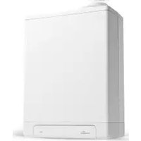
- INSTALLATION INSTRUCTIONS
- CONTENTS
- 1 EXPLANATORY NOTES AND SAFETY INSTRUCTIONS 6
- 2 SCOPE OF DELIVERY 12
- 3 REQUIRED COMPONENTS AND ACCESSORIES 13
- 9 COMMISSIONING THE SYSTEM 52
- 10 OPERATION AND READOUT 55
- 11 SETTINGS AND ADJUSTMENTS 58
- 12 FAULTS/NOTIFICATIONS 72
- 1 EXPLANATORY NOTES AND SAFETY INSTRUCTIONS
- 1.1 GENERAL EXPLANATION
- 1.1.1 ICONS WITHIN THE INSTALLATION INSTRUCTIONS
- CAUTION / IMPORTANT
- NOTE
- WARNING
- 1.1.2 SYMBOLS ON THE RATING PLATE
- INSTRUCTIONS
- CE DECLARATION
- FLAMMABLE REFRIGERANT
- RECYCLING
- 1.1.3 SYMBOLS ON THE PACKAGING
- 1.1.4 ABBREVIATIONS
- 1.1.5 INFORMATION ABOUT THE TEXT
- 1.2 GENERAL SAFETY INSTRUCTIONS
- IMPORTANT
- 1.4 POINTS OF ATTENTION FOR MAINTENANCE
- 1.5 REGULATIONS, STANDARDS AND SAFETY REQUIREMENTS
- REGULATIONS
- RELEVANT STANDARDS
- THE INSTALLATION
- FURTHER REQUIREMENTS
- 3.1 REQUIRED COMPONENTS
- 3.2 ACCESSORIES
- 4.1 GENERAL PRINCIPLE
- 4.2 ENERGY LABEL XTEND HYBRID HEAT PUMP SYSTEM
- 5.1 INDOOR UNIT
- 5.2 OUTDOOR UNIT
- 5.3 COMMON SPECIFICATIONS
- 6.1 FUNCTION
- 6.2 OPERATION
- 6.3 RATING PLATE INDOOR UNIT
- 7.1 FUNCTION
- 7.2 MAIN COMPONENTS OUTDOOR UNIT
- 7.4 RATING PLATE OUTDOOR UNIT
- 8.1 INSTALLATION OVERVIEW
- BUFFER TANK (INSTALL PARALLEL)
- INTERMEDIATE VESSEL (INSTALL IN SERIES)
- 8.2 DISTANCE BETWEEN THE INDOOR AND OUTDOOR UNITS
- NOTES
- OIL RETURN MEASURES
- 8.3 INSTALLING THE INDOOR UNIT
- 8.3.1 INSTALLATION LOCATION
- 8.3.2 MOUNTING THE INDOOR UNIT
- 8.3.3 REMOVING AND REPLACING THE FRONT COVER
- REPLACING THE FRONT COVER
- 8.4 WATER-SIDE CONNECTION
- 8.4.1 CONNECTING THE INDOOR UNIT AND THE BOILER USING THE LOW LOSS HEADER
- 8.5 SETTING UP THE OUTDOOR UNIT
- 8.5.1 POINTS OF ATTENTION FOR LOCATION
- 8.5.2 TRANSPORT
- 8.5.3 INSTALLING THE OUTDOOR UNIT
- ON A WALL
- CONNECTING THE DRAIN PLUG
- 8.6 REFRIGERANT CONNECTIONS
- 8.6.1 POINTS OF ATTENTION FOR REFRIGERANT LINES
- 8.6.2 MAKING REFRIGERANT CONNECTIONS TO THE INDOOR UNIT
- LIQUID LINE (SEE EXAMPLE)
- GAS LINE
- 8.6.3 MAKING REFRIGERANT CONNECTIONS TO THE OUTDOOR UNIT
- 8.6.4 STRENGTH TEST AND TIGHTNESS TESTING
- APPROPRIATE PPE MUST BE WORN AT THIS STAGE
- 8.6.5 CREATING A VACUUM IN THE REFRIGERANT LINES
- 8.6.6 REFRIGERANT ACTIONS
- EXAMPLE ADDING REFRIGERANT
- 8.6.7 INSULATING THE REFRIGERANT LINES
- 8.6.8 EMPTYING THE METER SET
- 8.6.9 CHECKING THE REFRIGERANT ACTIONS
- 8.7 MAKING ELECTRICAL CONNECTIONS
- 8.7.1 POINTS OF ATTENTION FOR ELECTRICAL INSTALLATION
- 8.7.2 ELECTRICAL INSTALLATION OVERVIEW
- 8.7.4 ELECTRICAL DIAGRAM OUTDOOR UNIT
- 8.8 ROUTING AND CONNECTING CABLES
- 8.8.1 WIRING THE OUTDOOR UNIT TO THE INDOOR UNIT
- CONNECTING THE OUTDOOR UNIT
- PLEASE NOTE
- CONNECTING THE INDOOR UNIT
- 8.8.2 CONNECTOR PLUG INFORMATION
- 8.8.3 WIRING THE BOILER TO THE INDOOR UNIT
- CONNECTING AN OPENTHERM BOILER
- ADDITIONAL INFO FOR BOILER SETTINGS VIA OPENTHERM
- CONNECTING AN ON/OFF BOILER
- THE CONNECTION MUST BE POTENTIAL-FREE FAILURE TO COMPLY WILL RESULT IN IRREPARABLE DAMAGE BEING CAUSED
- ADDITIONAL INFO FOR BOILER SETTINGS VIA ON/OFF
- 8.8.4 WIRING THE INDOOR UNIT TO AN EXISTING BOILER
- 8.8.5 CONNECTING THE ROOM THERMOSTAT TO THE INDOOR UNIT
- OPTION 1 (PREFERRED)
- CONNECTING AN OPENTHERM ROOM THERMOSTAT
- OPTION 2
- CONNECTING AN ON/OFF ROOM THERMOSTAT
- FOR THERMOSTATS WITH HYSTERESIS
- FOR PROPORTIONAL BAND THERMOSTATS
- 8.8.6 WIRING THE OUTDOOR SENSOR TO THE INDOOR UNIT (OPTIONAL)
- CONNECTING THE OUTDOOR SENSOR T42
- 8.8.7 WIRING A T43 NTC TEMPERATURE SENSOR TO THE INDOOR UNIT (OPTIONAL)
- CONNECTING THE EXTERNAL TEMPERATURE SENSOR T43
- ENSURE THAT THE SENSOR IS FIRMLY ATTACHED, SO THAT IT IS IN GOOD CONTACT WITH THE PIPEWORK AT ALL TIMES
- 8.8.8 INSTALLING AND USING THE COMFORT TOUCH ROOM THERMOSTAT
- INSTALLATION
- 8.8.9 COMFORT TOUCH APP
- 8.8.10 CONNECTING A SECONDARY PUMP
- 9.1 PREPARATORYWORK
- 9.2 FILLING, CLEANING AND VENTING THE CENTRAL HEATING SYSTEM
- 9.2.1 CLEANING AND FLUSHING THE CENTRAL HEATING SYSTEM
- 9.2.2 FILLING AND VENTING THE CENTRAL HEATING SYSTEM
- 9.2.3 CHECKING THE HEATING CIRCUIT
- 9.3 CONFIGURATION PROCEDURE
- 10 OPERATION AND READOUT
- 10.1 MULTICOLOUR LED DESCRIPTION
- PRIMARY COLORS
- SECONDARY COLOR
- 10.2 CONNECTIVITY PROCEDURE WIFI CONTROL SCREEN
- 10.2.1 QUICK GUIDE (QUICK CONNECTION VIA QR-CODES)
- 10.2.2 MANUAL CONNECTION
- 10.3 WI-FI CONTROL SCREEN DESCRIPTION
- 10.3.1 OVERVIEW (MAIN PAGE)
- 10.3.2 CONNECTIONS
- 10.3.3 SETTINGS (FOR THE END USER AS WELL AS THE INSTALLER)
- 10.3.4 SERVICE (SPECIFICALLY FOR INSTALLER)
- 11.1 SETTINGS (WI-FI CONTROL SCREEN)
- 11.1.1 DISCRIPTION DAY PROGRAMS
- SILENT MODE
- SETTING SILENT MODE
- HEAT PUMP BLOCKAGE MODE
- SETTING THE HEAT PUMP BLOCKAGE
- 11.1.2 TIME SETTINGS
- 11.1.3 HYBRID MODE
- 11.2 SERVICE MENU (SPECIFICALLY FOR THE INSTALLER)
- 11.2.1 ACCESS TO THE SERVICE MENU
- 11.2.2 INSTALLATION WIZARD
- 11.2.3 TOOLS
- PUMP VENTING
- ACTIVATING THE SYSTEM PUMP
- MANUAL DEFROSTING
- HEAT PUMP SERVICE MODE (MINIMUM)
- HEAT PUMP SERVICE MODE (MAXIMUM)
- BOILER SERVICE MODE
- PUMPING OUT REFRIGERANT
- 11.2.4 PARAMETERS (ADJUSTMENT)
- 11.2.5 STATISTICS
- 11.2.6 FIRMWARE (UPDATE)
- 11.3 ADJUSTING THE HYBRID WORK MODE
- 11.3.1 SETTING THE HYBRID MODE
- 4 = MAXIMUM HEAT PUMP USE
- 5 = ONLY THE BOILER
- 11.4 SETTINGS FOR ACTIVATING THE BOILER
- HEAT PUMP MALFUNCTION
- DELAY TIME BEFORE THE INVOLVEMENT OF THE BOILER AFTER INITIATING HEATING
- 11.4.1 SETTING A REDUCED TEMPERATURE
- REDUCED TEMPERATURE SETPOINT
- 11.5 ROOM HEATING SETTINGS (CH MODE)
- 11.6 PARAMETER LIST
- 12.1 FAULT CODES
- 12.2 NOTIFICATION CODES
- 12.3 OTHER MALFUNCTIONS
- 12.3.1 MALFUNCTION WITHIN THE INDOOR UNIT
- 12.3.2 CH DOES NOT GET UP TO TEMPERATURE
- 12.3.3 CH INSTALLATION STAYS TOO HOT
- 12.3.4 MALFUNCTION OF THE OUTDOOR UNIT
- CAUTION
- 13.1 CLEANING THE FILTER
- 13.2 INDOOR UNIT MAINTENANCE WORK
- 13.3 OUTDOOR UNIT MAINTENANCE WORK
- 13.4 DECOMMISSIONING THE SYSTEM
- 13.4.1 REMOVING AND RECYCLING
- 13.4.2 COLLECTING REFRIGERANT
- PROCEDURE
- 13.4.3 LABEL
- THE PRODUCT MUST BE REGISTERED VIA THE INTERNET AT WWW.INTERGASHEATING.CO.UK OR ON THE INTERGAS MIREG WEBSITE WWW.MYINTERGASREGISTRATION.CO.UK OR BY RETURNING THE WARRANTY CARD
- WEBSITE: WWW.INTERGAS.CO.UK
- TECHNICAL & SERVICE: SERVICE@INTERGAS-HEATING.CO.UK
- SERVICE PROVIDER
- SERVICE & INTERIM HEAT PUMP WORK RECORD
- INTERGAS HEATING LTD
Brand : Intergas
Model : Xtend Split
Category : Water pump