IP-6600 - Printer SEIKO - Free user manual and instructions
Find the device manual for free IP-6600 SEIKO in PDF.

User questions about IP-6600 SEIKO
0 question about this device. Answer the ones you know or ask your own.
Ask a new question about this device
Download the instructions for your Printer in PDF format for free! Find your manual IP-6600 - SEIKO and take your electronic device back in hand. On this page are published all the documents necessary for the use of your device. IP-6600 by SEIKO.
USER MANUAL IP-6600 SEIKO
natural_image
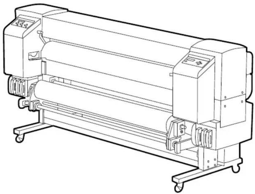
Line drawing of a large industrial printing press machine with control panels and wheels (no text or symbols)Read this User's Guide to use the printer safely and properly. Keep this manual in a place where you can quickly access it at any time.
Seiko I Infotech Inc.
IP-6600 Solvent Ink Color Inkjet Printer User's Guide
Documents Number U00086051203
First Edition, December 2003
Second Edition, February 2004
Third Edition, September 2004
Fourth Edition, April 2005
Copyright © 2003, 2004, 2005 by Seiko I Infotech Inc.
All rights reserved
Seiko I Infotech Inc. reserves the right to make changes without notice to the specifications and materials contained herein and shall not be responsible for any damages (including consequential) caused by reliance on the materials presented, including but not limited to typographical, arithmetic, or listing errors.
Please address any questions, comments, and suggestions to:
Seiko I Infotech Inc.
8, Nakase 1-chome, Mihamaku, Chiba-shi.
Chiba 261-8507, Japan
This manual acknowledges the following trademarks:
SII is a trademark of Seiko I Infotech Inc.
All other trademarks are the properties of their respective companies.
This equipment has been tested and found to comply with the limits for a Class A digital device, pursuant to Part 15 of the FCC Rules. These limits are designed to provide reasonable protection against harmful interference when the equipment is operated in a commercial environment.
This equipment generates, uses, and can radiate radio frequency energy and, if not installed and used in accordance with the instruction manual, may cause harmful interference to radio communications. Operation of this equipment in a residential area is likely to cause harmful interference in which case the user will be required to correct the interference at his own expense.
CE
Thank you very much for purchasing the IP-6600 Color Inkjet Printer (simply called the printer below).
This printer is a color inkjet printer that adopts solvent ink, supports 64 inch media width, and built-in SCSI interface.
This manual, the IP-6600 User's Guide, describes the features of the printer, names of components, information to be known before use, and basic operations, such as how to turn the power on and off and set media and ink.
The following items should be read before reading Section 1.
- Deliverables
- Safety precautions
- Handling precautions
- Manual legend (notation rules)
Read these items to use the printer safely and properly. Keep this manual in a place where you can quickly access it at any time.
The printer components, including options, are installed on the main unit on delivery. Make sure that the following items are present. If any parts are missing or damaged, contact the shop where you purchased the product or the nearest service dealer.
Basic components
natural_image
Line drawing of a large industrial printing press machine with control panels and wheels (no text or symbols)Printer main unit <1>
• Built-in SCSI interface.
• Including a winding unit.
Accessories
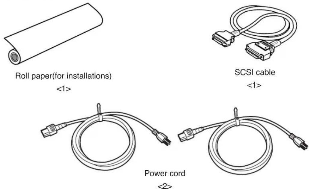
• Power cord for printer
- Power cord for heater
natural_image
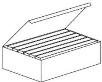
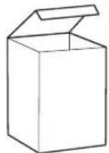
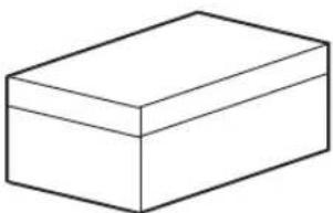
Line drawing of an open box with multiple compartments (no text or symbols)Starter kit 6 colors IP6-100
(Y, M, C, Bk, Lc, Lm)
<1>
User's Guide
<1 copy>
natural_image
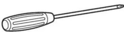
Line drawing of a screwdriver with ridged handle and pointed tip (no text or symbols)- screw driver
(for head up/down adjustment)

natural_image
Simple line drawing of a container with a handle and cap (no text or symbols)Waste ink bottle IP6-109
<1>
natural_image
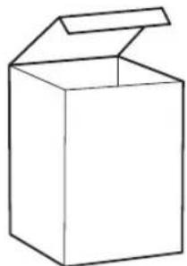
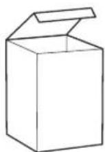
Simple line drawing of an open box (no text or symbols)Maintenance kit IP6-108
<1 set>
• Cap cleaning liquid: 100 ml
• Wiper cleaning liquid: 100 ml
- Cleaning swab: 50 pieces
- Syringe: 10 pieces
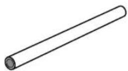
Paper tube 64" (For winding unit)
<1>
Options
- Dryer 64 (IP-260) : 1
• Dryer 64 for North America (IP-263) : 1
• Roll Cover 64 (IP-261) : 1
• Exhaust Attachment (IP-262) : 1
• PS RIP (Photo Print 4 Dx) (IP-540) : 1
• PS RIP (Photo Print 4 Server) (IP-541) : 1
Consumables
Maintenance Kit IP6-108
<1 set>
• Cap cleaning liquid: 100 ml
• Wiper cleaning liquid: 100 ml
- Cleaning swab: 50 pieces
- Syringe: 10 pieces
natural_image
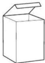
Simple line drawing of a 3D rectangular block (no text or symbols)Cleaning Kit IP6-117 <1 set>
- Cleaning liquid cartridge: 6
- Dummy cartridge: 6

natural_image
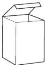
Simple line drawing of a 3D rectangular box (no text or symbols)Storage Kit IP6-137 <1 set>
- Maintenance liquid cartridge: 6
- Dummy cartridge: 6
Cap cleaning liquid: 6 bottles
IP6-138 < 1 set >
Cap cleaning liquid (100ml) : 6 bottles
Wiper cleaning liquid: 6 bottles
IP6-139 < 1 set >
• Wiper cleaning liquid (100ml) : 6 bottles
- Syringe: 10 pieces
Cleaning swab
IP6-147
<300 pieces>
natural_image
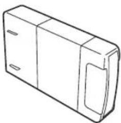
Line drawing of a rectangular electronic device with two side panels (no text or symbols)Ink cartridges IP6-XXX
(Y, M, C, Bk, Lc, Lm)
See page 1-8 for the item number.
natural_image
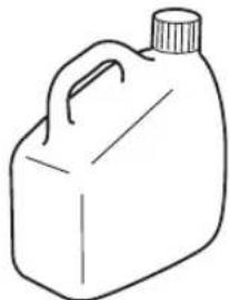
Line drawing of a plastic container with a handle and cap (no text or symbols)Waste ink bottle IP6-109
<1>
The following symbols are used in this manual to ensure the proper use of the printer and to prevent the printer from being damaged. Follow the instructions marked with these symbols.
 WARNING WARNING | Serious personal injury or death:Failure to follow the guidelines marked with this symbol could result in serious personal injury or death. |
 CAUTION CAUTION | Minor personal injury or product and/or peripheral damage:Failure to follow the guidelines marked with this symbol could result in minor personal injury or product and/or peripheral damage. |
Example of symbols:

This symbol ( ) denotes items that require special care while executing a certain procedure or operation.

This symbol (⊗) denotes items that are forbidden.

This symbol (●) denotes items you should follow to prevent accidents or injury.

WARNING

Use the power supply voltage specified on the nameplate. DO NOT plug several devices into one electrical outlet as this might result in fire or electric shock.

Make sure the printer is well grounded. If not, a short circuit may cause fire or electrical shock.

DO NOT disassemble or remodel the printer. DO NOT repair the printer by yourself. Doing so may cause fire, electric shock or other accidents.

DO NOT damage, break, process, or heat the power cable. If it is damaged, replace it with a new one. Using a damaged power cable may cause fire or electric shock.

NEVER use the printer in a place of extreme humidity or any place where it can possibly be splashed by any liquids. If any liquids get into the printer, it could lead to fire, electric shock, or other serious accidents.

DO NOT remove the covers attached to the printer because they contain high-voltage and extremely hot parts. Careless removal might result in an electric shock or burn.

DO NOT allow metal or liquids to touch the internal parts of the printer. Doing so may cause fire, electric shock, or other accidents.

DO NOT disconnect or connect the power cable with wet hands. Doing so may lead to electric shock.

Turn the printer off and unplug the power cable immediately after it thundered.

WARNING

Power OFF the printer and unplug the power cable from the power outlet in any of the following cases:
- When putting your hands inside the printer.
- Smoke, strange noise or smells generate from the printer.
- A piece of metal or any liquid touches the internal parts or slot of the printer.
- An error requiring service by a service center occurs.

DO NOT put your hand into the paper delivery slot as it may lead to injury by the cutting device.

Do not leave the printer stained with ink.
The coating of the printer may be damaged.

The ink used for the device contains organic solvent
(Ethylenglycolmonbutyleteracetat).
Therefore, observe the local rules strictly related to organic solvent stuff.

The ink used for the device contains organic solvent
(Ethylenglycolmonobutyletheracetat), Since the ink is flammable, never use fire when using the device.

Do not swallow ink or avoid its splashes on the eye. If it gets into the eye, wash it off with a clean running water and consult a doctor as required. If it is swallowed, do not try to vomit it forcefully, but cunsult a doctor.
Keep ink cartridges out of reach of children.

CAUTION

Handle the paper rolls with care because they are very heavy. If you drop them, it could lead to personal injury.

Hold the electric cable by the plug when connecting or disconnecting it. Failing to do so may cause the cable to fray or break which could lead to electric shock and/or fire.

DO NOT get ink on your skin or clothes. Wash off any ink immediately with soapy water.

DO NOT put any paper rolls on an unstable table or a tilted surface as they could fall leading to an injury.

The heater will be hot. Pay attention not to touch and not to be burned.
In order to ensure the safe operation of the printer heed all of the cautions and warnings contained throughout this manual.
Power Supply
- Install the printer near an easily accessible electrical outlet.
- Do not provide power to the printer through the same power line as for noise-generating devices, such as a motor.
- Use the power supply matched with the specification of the printer.
- Connect the power cable to an electrical outlet. Do not plug several devices into one electrical outlet.
Printer
- Do not place anything on top of the printer. Do not rest your elbows on the printer.
- Open and close the top cover gently from the front of the printer with both hands.
- Before connecting or disconnecting the interface connector, turn the printer off.
- Do not clean the surface of the cover with benzene or paint thinner. The coating may come off or deteriorate.
Wipe the cover clean with a soft cloth. If the cover is very dirty, use a cloth moistened with a neutral detergent. - Do not touch the ink-jet head surface.
Regular Inspection and Maintenance
The following regular inspection and maintenance must be performed in terms of characteristics of solvent ink.
- Clean the capping unit and wiper blade every day.
- Check moisture of wiper sponge every day.
- Perform the head cleaning every one month.
- Perform the service cleaning when leaving the printer for long time (2 weeks or more at power off state.)
- Perform the head wash and the ink charge before printing when leaving the primer for long time.
See pages 2-62 and 2-73 for regular inspection and maintenance.
Consumables
- Always use the recommended consumables (media, ink, etc.). Failure to follow this instruction may cause poor print quality or a breakdown.
- Do not use ink past the date of expiration as this may cause a breakdown.
- Put a used ink cartridge into a plastic bag and dispose of it as an industrial waste. Observe any regulations for disposal of waste ink bottles.
- Do not get ink on your skin or clothes. Wash off any ink immediately with soapy water.
- Check waste ink bottle regularly so as not to leak the waste ink.
- When the waste ink bottle is installed or removed, spread the stain preventing sheet so as not to stain the floor with spilt ink.
- Store ink in a dark and cool place.
NEVER store ink in a high temperature or direct sunshining place.
Doing so, ink may cause characteristic changes. - Do not attempt to disassemble ink cartridges.
- Media for solvent ink on the market can be used for this printer.
Manual Legend (Notational rules)
This manual uses the notational rules for marks, keys, LCDs, and LEDs:
Marks

WARNING
Boxes marked with a "WARNING" describe points of caution for avoiding serious personal injury.

CAUTION
Boxes marked with a "CAUTION" describe points of caution for avoiding injury to yourself or damage to the printer.
NOTE
Boxes marked with a note describe precautions while handling the printer.

HINT: Hint mark
The hint symbol describes operations that make using or handling the printer easier.

Reference mark
This mark is followed by a reference section or page number.
Notation of Keys/LCDs/LEDs
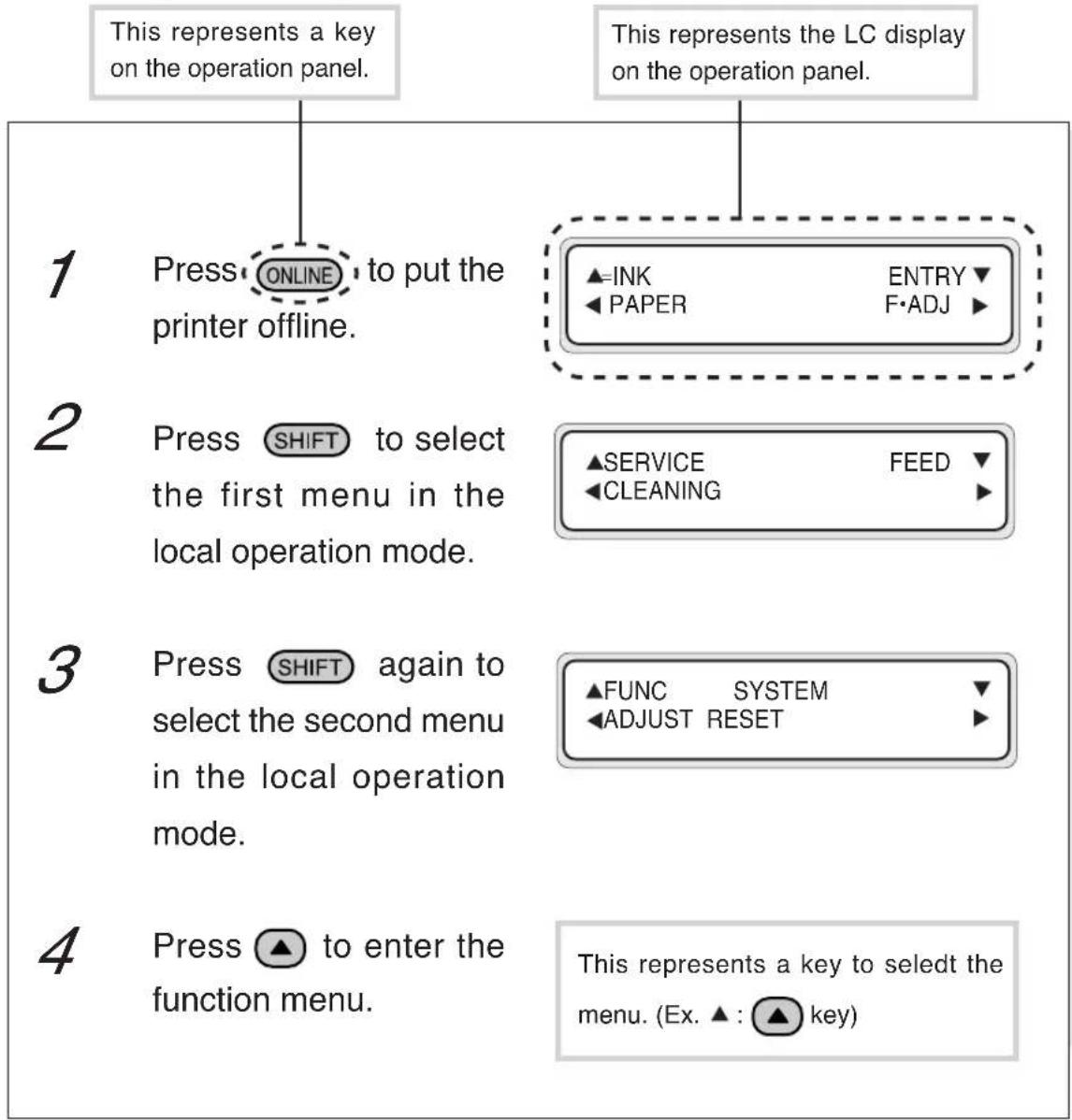
Example 1: Keys and messages shown on the LCDs in the text
flowchart
graph TD
    A["1. Press ONLINE to put the printer offline."] --> B["2. Press SHIFT to select the first menu in the local operation mode."]
    B --> C["3. Press SHIFT again to select the second menu in the local operation mode."]
    C --> D["4. Press ▲ to enter the function menu."]
    E["▲=INK PAPER ENTRY F·ADJ"] --> F["▲SERVICE CLEANING FEED ▼"]
    F --> G["▲FUNC SYSTEM ADJUST RESET ▼"]
    G --> H["This represents a key to select the menu. (Ex. ▲: ▲key)"]
Example 2: LED's states in the text
LED's states of "On", "flashing", and "Off" are characterized by the following symbols:
On
Flashing
Off
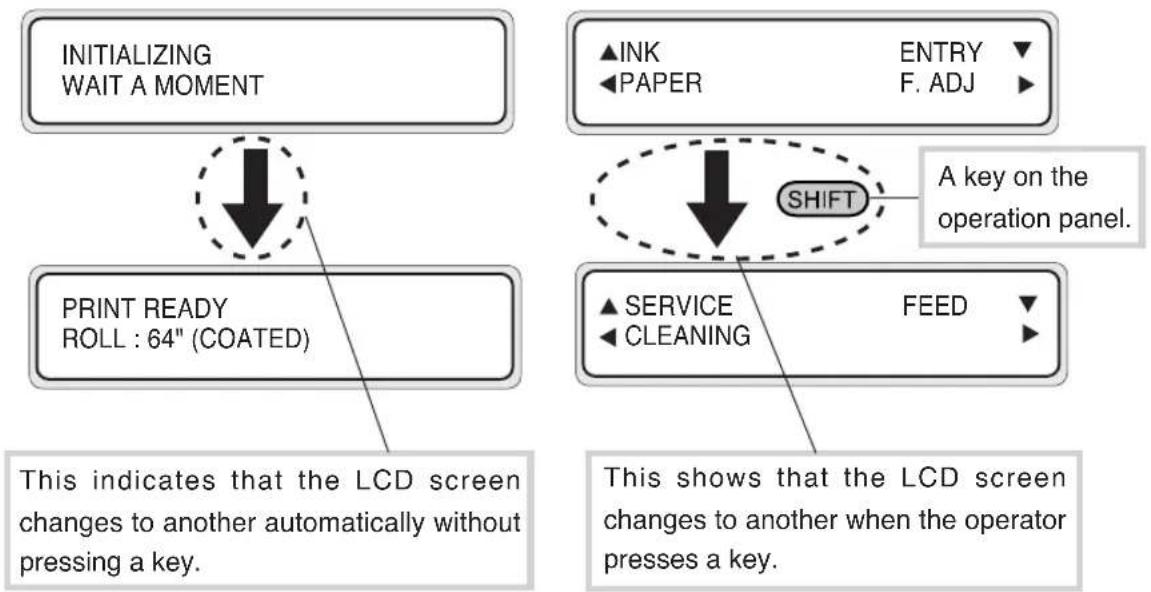
Example 3: LCD's state transitions and key operations in the text
flowchart
graph TD
    A["INITIALIZING WAIT A MOMENT"] --> B["PRINT READY ROLL : 64" (COATED)"]
    B --> C{A key on the operation panel.}
    C --> D["SHIFT"]
    D --> E["▲ SERVICE FEED"]
    D --> F["▲ INK PAPER ENTRY F. ADJ"]
    D --> G["▲ SERVICE CLEANING"]
    H["This indicates that the LCD screen changes to another automatically without pressing a key."] --> B
    I["This shows that the LCD screen changes to another when the operator presses a key."] --> D
TABLE OF CONTENTS
Introduction
Deliverables .... i
Safety Precautions....iv
Handling Precautions...... viii
Manual Legend (Notational rules).... x
Section 1 Getting Started (Basic knowledge) 1-1
Operating Conditions 1-2
Installation Space 1-2
Environmental Conditions 1-3
Consumables 1-5
Media/Paper 1-5
Ink 1-8
Waste Ink Bottle 1-10
Maintenance Kit 1-11
Cap Cleaning Liquid 6 Bottles 1-12
Wiper Cleaning Liquid 6 Bottles 1-12
Cleaning Swab 1-12
Storage Kit 1-12
Cleaning Kit 1-12
External Views, Part Names, and Functions 1-13
Front 1-13
Rear 1-14
Heater 1-15
Operation Panel 1-16
Heater Control Panel 1-18
Dryer 64 (Option) 1-19
Roll Cover 64 (Option) 1-19
Exhaust Attachment (Option) 1-19
PS RIP (PhotoPrint 4 DX) (Option) 1-19
PS RIP (PhotoPrint 4 Server) (Option) 1-19
LCD Messages and Printer State 1-20
Messages on the LCD 1-20
F/W version checking method 1-24
F/W version checking method 1-24
Added Functions in V2.00 1-24
Section 2 Basic Operations 2-1
Connecting with Computer 2-2
System configuration (connection example) 2-2
Connection procedure 2-2
Turning the Power On/Off 2-5
Turning the Power On 2-6
Turning the Power Off 2-9
Replacing the Paper Roll 2-11
Installing Paper Roll in the Printer 2-11
Removing the Paper Roll from the Printer 2-17
Replacing Paper Roll with Another 2-18
Replacing Empty Paper Roll.... 2-18
Replacing Jammed Paper Roll 2-18
Installing/Removing Cut Sheet in/from the Printer 2-19
Paper Feed Adjustment Correction Value Setting 2-19
Change during online printing 2-24
Head print position adjustment 2-24
Replacing Ink Cartridges 2-31
Ink Cartridge Replacement Procedure 2-31
Replacing Empty Ink Cartridge 2-33
If an Ink Cartridge Is Not Installed 2-34
Replacing Cartridges during Printing 2-35
If an Ink Cartridge Is Not Detected 2-37
Replacing the Waste Ink Bottle.... 2-38
Waste Ink Bottle Replacement Procedure.... 2-38
If the Waste Ink Bottle Is Full 2-40
If the Waste Ink Bottle Is Not Installed 2-41
Head Cleaning "CLEANING" 2-42
Paper Feed "FEED" 2-44
Using the Origin Point Setting Function 2-45
Installing Paper on Winder.... 2-48
Changing Heater Control Setting Temperature 2-53
Using the Media Pressure Alternation Lever 2-56
Using the Head Up/Down Lever 2-57
Using the Media Edge Guard 2-59
Using the FAN Guard Slide Lever 2-60
Using the Print Pause/Restart and Cancel Keys 2-61
Inspection & Maintenance 2-62
Section 3 Operation Panel Menu Operations 3-1
Basic Menu Operation 3-2
Menu Hierarchical Structure 3-2
Menu Tree 3-3
Basic Operations and Keys 3-8
Operation Procedure for Choice Input, Value Input, Execution, and Character Input .... 3-9
Menu Operations 3-15
INK Menu 3-15
PAPER Menu 3-16
ENTRY Menu 3-17
F.ADJ Menu.... 3-35
SERVICE Menu 3-38
CLEANING Menu 3-41
FEED Menu 3-42
FUNC Menu.... 3-42
ADJUST Menu.... 3-44
SYSTEM Menu 3-47
RESET Menu.... 3-51
Section 4 Heater Controller Operation 4-1
Temperature Control.... 4-2
LCD Display 4-4
Parameter Setup Mode.... 4-6
Error Messages 4-10
Section 5 Troubleshooting 5-1
Troubleshooting 5-2
Clearing Paper Jam 5-3
When an Error Message Appears 5-4
Service Call Errors.... 5-4
Communication Errors 5-6
Operator Call Errors 5-7
When the Printer Fails to Work Correctly 5-11
When a Print Error Occurs.... 5-12
When There Is an Abnormal Sound 5-13
Appendix A-1
Basic Specifications ...... A-2
Printer Specifications ...... A-2
Options/Consumables ......A-3
Options ......A-3
Consumables.... A-4
Celsius and Fahrenheit Conversion List ...... A-5
CONTENTS-4
Section 1 Getting Started
(Basic knowledge)
This section provides necessary information to operate the printer. Familiarize yourself with the basics of the printer before reading Section 2 and later.
Contents of this section
Operating Conditions
Installation Space
Environmental Conditions
Consumables
Media/Paper
Ink
Waste Ink Bottle
Maintenance Kit
Cap Cleaning Liquid 6 Bottles
Wiper Cleaning Liquid 6 Bottles
Cleaning Swab
Storage Kit
Cleaning Kit
Maintenance Liquid Cartridge
External Views, Names of Parts, and Functions
Front
Rear
Heater
Operation Panel
Heater Control Panel
Dryer 64
Roll Cover 64
Exhaust Attachment
PS RIP (PhotoPrint 4 DX)
PS RIP (PhotoPrint 4 Server)
LCD Messages and Printer State
Messages on the LCD
F/W Version Checking Method
F/W Version Checking Method
Added Functions in V2.00
This section describes the operating conditions for the printer.
Installation Space
There must be a sufficient space around the printer for the replacement of frequently used parts, for the output of drawings, and for ventilation. In addition, the maintenance space, shown below, is required to repair the printer or replace components.
The installation/maintenance space is shown in the following figure.
■ Installation and maintenance space
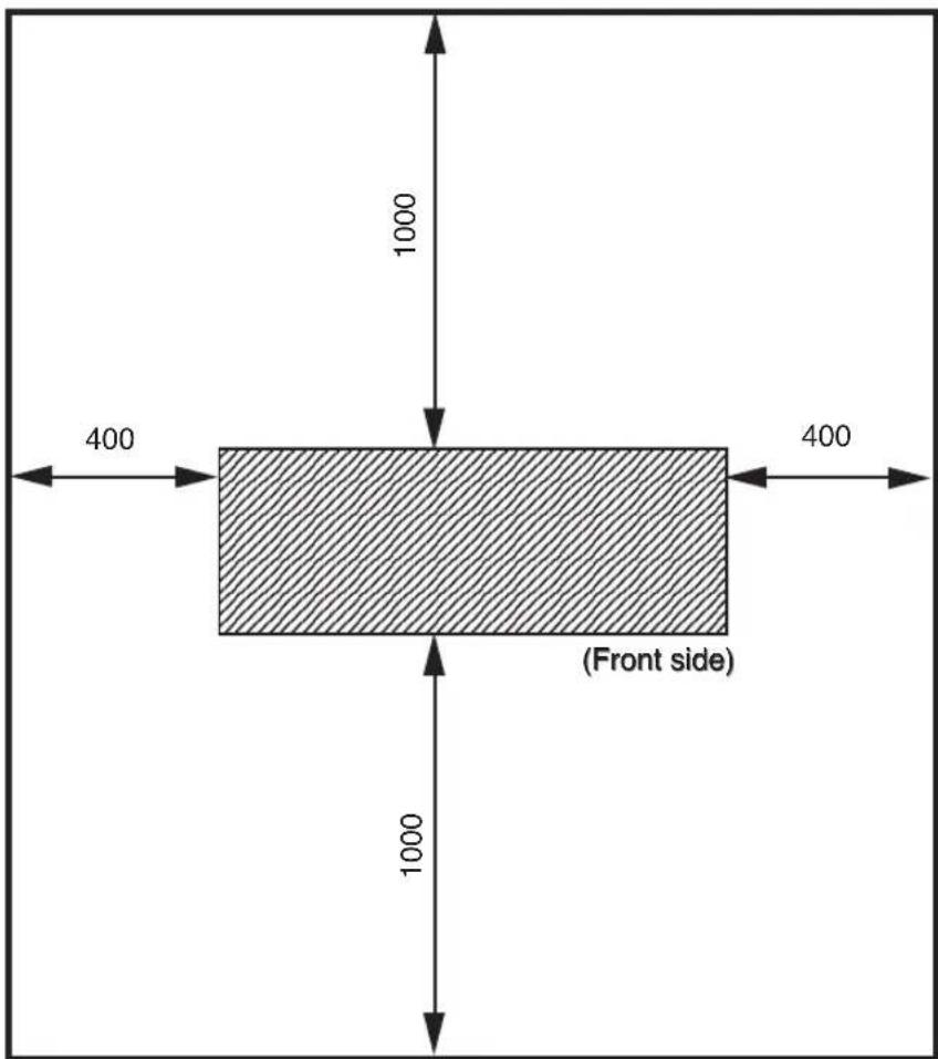
Height direction: 1700
(Unit : mm)
Environmental Conditions
■ Operating temperature and humidity levels
The printer should be used within the temperature and humidity levels shown below.
Temperature: 15 °C to 30 °C
Humidity: 30% to 70%

- T o obtain better print quality, use the printer within temperatures of 20 to 25 °C.
- When operating temperature is lower than 20 °C , the print speed goes down two-third of normal print speed to keep a good print quality.
- When the head temperature goes high, the print time is delayed.
NOTE
- When the printer is used out of range of the operating temperature and humidity, the print may be stopped and the print quality may be degraded.
■ Places where the printer must not be installed
Do not install the printer in the following places:
- Places exposed to direct sunlight
- Places subject to vibration
- Places with excessive dust
- Places subject to extreme changes in temperature or humidity
- Places near an air conditioner or a heater
- Places where the printer may get wet
- Places subject to direct air circulation from vents
- Places near a diazo copier that may generate ammonia gas
- Places with poor ventilation
- Unstable places
Media/Paper
■ Available media types
We prepared the following types of media:
- Glossy vinyle chrolide
- Matted vinyle chrolide
- Banner
Contact our service center for details.
■ Precautions for storing media
- A void direct sunlight and water regardless of before and after opening the package. Put paper in envelope to prevent dust and store media in a dry, cool and dark place.
- A void rapid change of temperature and humidity and store media with no condensing.
- Do not store media in standing condition to prevent disorder of media and damage of roll edge.
- Do not pile up media.
■ Precautions for disposing of paper
- Dispose of media in rule matched to the actual situation.
If there is a limitation for disposal regulations, follow the regulations.
■ Precautions for use
- A void a change of temperature and humidity after opening package.
Set media after leaving media in the operation environment for 3 hours or more. Use care for a change of humidity by turning ON/OFF the air conditioner.
- In terms of media characteristics, curl of paper in low humidity and wrinkle of media in high humidity may occur easily.
Use paper in normal temperature and humidity environment (around 23 °C and 50%RH).
- Do not use scratched, wrinkled, curled, or stained with dust media.
Especially, roll edge (both edges of roll) affects media feeding. Also, do not drop or wet the media. If doing so, it may cause bad effect to print quality and causes a malfunction.
- Hold margins of the media so as not to touch the print surface.
Adhesion of sebaceous matter or sweat may cause bad effect to print quality.
- Amend mis-roll of the media before setting.
■ Precautions for handling prints.
- Do not touch the print surface before drying up the ink.
Hold margins of the media for handling.
Especially use care before 24 hours after printing. - Rubbing print surface causes color fading or color transfer.
Do not pile print surface to prevent color transfer. - Do not pile together with copy prints or laser prints to prevent sticking due to ink or toner.
- Do not rub, scratch, or hold the media to prevent pealing.
- Do not rub or leave the paper in wet condition to prevent blurring.
■ Other precautions
- Media causes color fading and a change in quality in getting old.
Check paper condition and use well-conditioned paper. - Paper dust due to cutting may cause float of coating.
- When using vinyl (with glue), adhesive matter (with glue) may be sticked to the platen.
In this case, wipe up the adhesive matter referring to "Section 2, Inspection & Maintenance".
Sticking of adhesive matter may cause paper jamming.
Ink
■ Ink types
Use our recommended ink cartridges listed below.
| .∅Nmetl | r | |
| IP6-101 | Y (Yellow) | 1000 ml |
| IP6-102 | M (Magenta) | 1000 ml |
| IP6-103 | C (Cyan) | 1000 ml |
| IP6-104 | Bk (Black) | 1000 ml |
| IP6-105 | Lc (Light Cyan) | 1000 ml |
| IP6-106 | Lm (Light Magenta) | 1000 ml |
olocknl
NOTE
- Failure to use the recommended ink cartridge may lead to a deterioration of the print quality or a printer malfunction.
- The valid period of the ink is 12 months after the manufacture date.
- Do not shake ink cartridges before use.
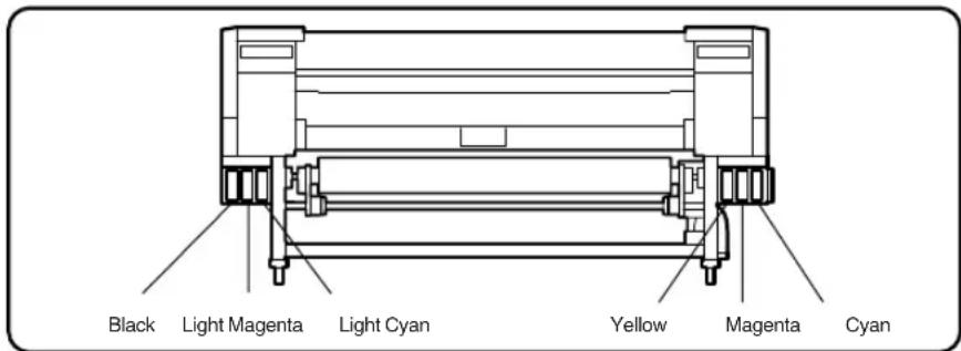
- All six color cartridges must be installed.
If any of the cartridges is removed, a new one must be installed.
Ink cartridges must be installed in all six slots. The positions of ink cartridges are specified by color. (See the figure below.)

WARNING
- Never bring the ink close to fire. Failure to follow this warning might result in fire.

CAUTION
- Do not swallow ink or avoid its splashes on the eye. If it gets into the eye, wash it off with a clean running water and consult a doctor as required. If it is swallowed, do not try to vomit it forcefully, but see a doctor.
- Do not attempt to disassemble ink cartridges.
■ Precautions for ink storage and processing

CAUTION
- Securely put a used ink cartridge into a plastic bag and dispose of it as an industrial waste. Observe any regulations for disposal of ink cartridges.
NOTE
- Ink has an expiration date. When it expires, the printer quality may deteriorate or the printer may malfunction.
- Store ink cartridges in a dry, cool and dark place.
- Always use the recommended consumables (paper, ink, etc.). Failure to follow this instruction may cause poor print quality or a breakdown.
Waste Ink Bottle
Use our recommended waste ink bottle listed below.
| .oNmetl | ||
| 901-6PI | e | c |

WARNING
- Never put the waste ink bottle near open flames. Failure to follow this warning might result in fire.

CAUTION
- Do not swallow ink or avoid its splashes on the eye. If it gets into the eye, wash it off with a clean running water and consult a doctor as required. If it is swallowed, do not try to vomit it forcefully, but see a doctor.
NOTE
- Install the waste ink bottle securely.
- A waste ink bottle must always be installed. If it is removed for replacement, a new one must be installed.
■ Precautions for handling the waste ink bottle

CAUTION
- After use, securely fasten the attached cap and dispose of this product as industrial waste. If you have any questions, please contact your nearest sales office.
NOTE
- When the waste ink bottle is installed or removed, hold it with both hands with its mouth facing up. If not, waste ink may spill from the bottle.
Maintenance Kit
For cleaning the cap and wiper, use our specified cleaning liquid respectively listed below.
| .oN | metl | s |
| 801-6PI | Cap cleaning liquid | 100 ml |
| Wiper cleaning liquid | 100 ml | |
| Cleaning swab | 50 pieces | |
| Syringe | 10 pieces |

CAUTION
- Do not swallow ink or avoid its splashes on the eye. If it gets into the eye, wash it off with a clean running water and consult a doctor as required. If it is swallowed, do not try to vomit it forcefully, but see a doctor.
Cap Cleaning Liquid 6 Bottles
| Item No. | Remarks | Quantity |
| IP6-138 | Cap cleaning liquid (100ml) | 6 |
Wiper Cleaning Liquid 6 Bottles
| Item No. | Remarks | Quantity |
| 135 | Wiper cleaning liquid (100ml) | 6 |
| Syring | 10 |
Cleaning Swab
| .oNmetl | |
| IP6-147 | 300 pieces |
ks
Storage Kit
| Item No. | Remarks Quantity | |
| IP6-137 | Maintenance liquid cartridge (IP6-107) 6 | |
| Dummy cartridge (IP6-118) 6 |
Cleaning Kit
| Item No. | Remarks Quantity | |
| IP6-117 | Cleaning liquid cartridge (IP6-119) 6 | |
| Dummy cartridge (IP6-118) 6 |
This section shows the external views of the printer, the names of parts of the printer and describes their functions.
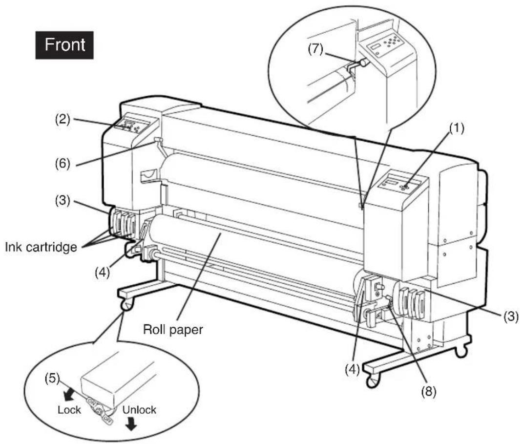
(1) Operation panel The lamps and LCD, which indicate the printer status, and keys for setting functions are located on the operation panel.
(2) Heater control panel The keys for setting heater temperature are located on the heater control panel.
(3) Ink holder Holds the ink cartridge.
(4) Flange Sets paper roll.
(5) Caster Unlocks the caster to move the printer, and lock it to secure the printer.
(6) Paper pressure alternation lever
Alternates paper pressure depending on the paper thickness.
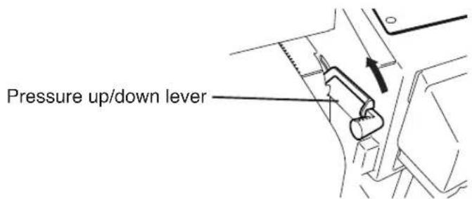
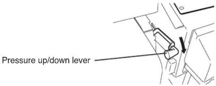
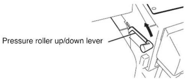
(7) Pressure roller up/down lever
Presses down the paper after inserting the paper into the paper supplying part and releases the pressing down of the paper.
(8) Paper-out release lever (ME lever)
Releases paper-out detection sensor.
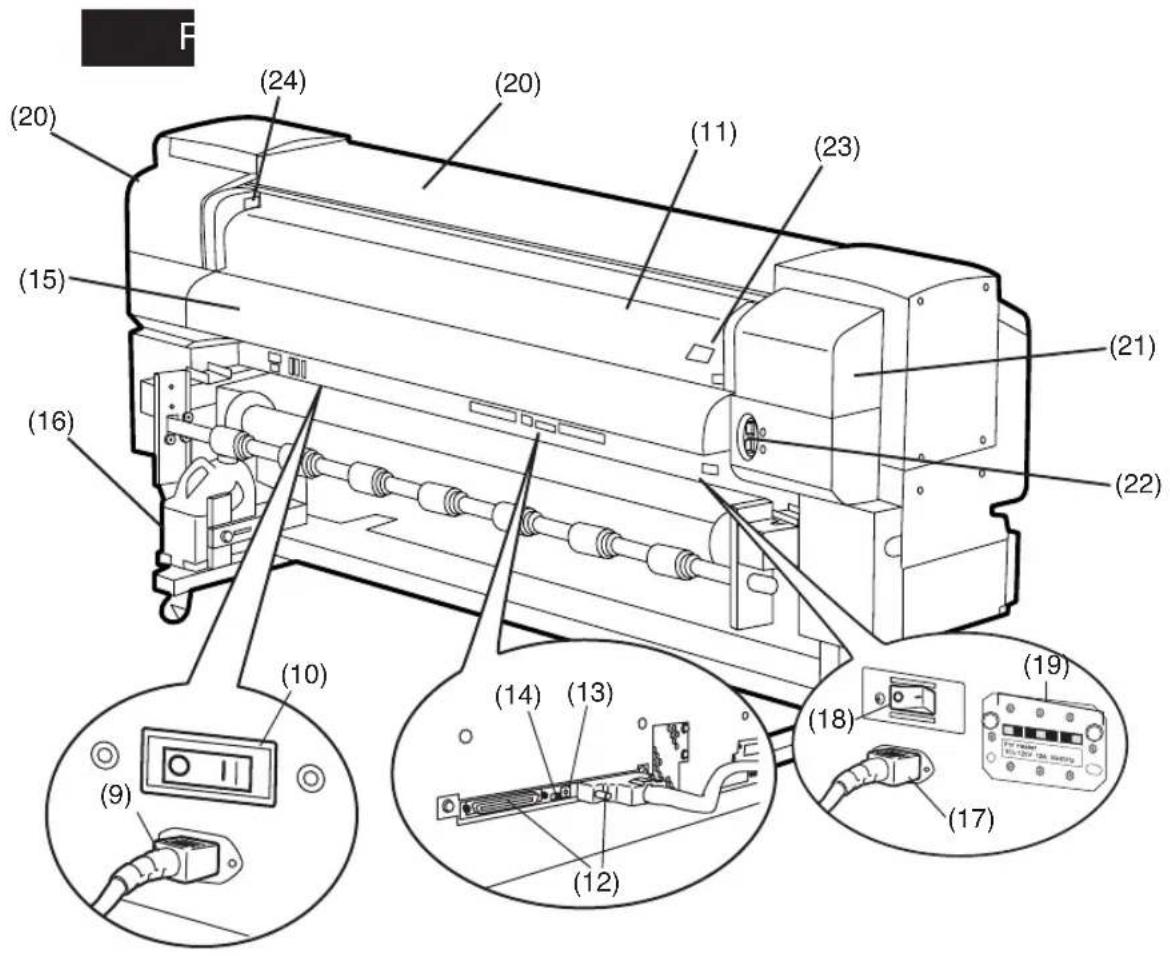
(9) Power receptacle
(10) Printer switch
(11) Rear cover
(12) SCSI connector
(13) ID switch SCSI controller
(14) Terminator switch
(15) Paper outlet
(16) Waste ink bottle
(17) Power receptacle
(18) Heater switch
(19) 100 V/200 V alternation switch
(20) Cap cover
(21) Wiper cover
(22) Print stop/restart, cancel keys
(23) FAN guard potitioning slide bar
(24) Head up/down lever
Heater
The printer builts in three heaters for fixing and stabilizing print image on the print paper.
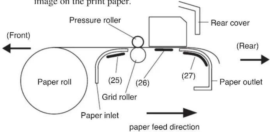
(25) Front heater (Front) Preheats the paper.
(26) Print heater (Rear) Infiltrates ink into the paper and fixes ink.
(27) Rear heater (Finish) Drys ink and stabilizes print image.
* Three heaters are controlled separately.

WARNING
- Heaters become hot. NEVER touch the heaters. If doing so, it could lead to burn.
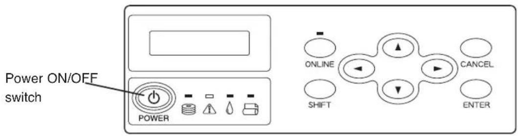
Operation Panel
Keys, LEDs, and the LCD are laid out on the operation panel as follows. It has a buzzer to alert errors or invalid key operations.
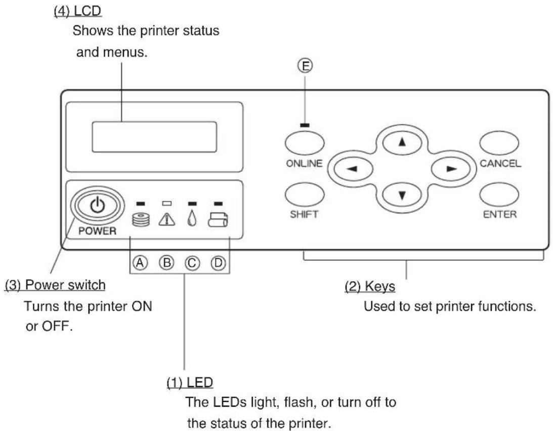
■ Functions of LCD, LEDs and keys
| Number Name Function | ||
| (1)LED | (A) Data LED (green) | Shows the data reception state.- F lashing : Data is being received from the computer- O ff : No data is being received |
| (B) Error LED (orange) | Indicates whether an error has occurred.- O n : An error has occurred- F lashing : Warning state (Winder time out error)- O ff : Normal (No error has occurred.) | |
| (C) Ink LED (green) | Shows whether there is the ink cartridge or indicates a warning.- O n : A l l i n k cartridges are present.- F lashing : Ink is running out. (One of color inks has run out.)- O ff : N o i n k (One of color inks has run out.) | |
| (D) Paper LED (green) | Shows whether paper is set.- O n : Paper is set. (Roll paper or cut sheet is set.)- O ff : N o p a p e r ( N e ither roll paper nor cut sheet is set.) | |
| (E) Online LED (green) | Shows whether the printer is online or offline.- O n : O n l i n e- F lashing : Online pause mode- O ff : O ff l i n e | |
| (2)Key | ONLINE key Switches between online and offline states. | |
| SHIFT Key | Used as an auxiliary key for parameter input (switches the menu level display). | |
| CANCEL Key Cancels an input parameter. | ||
| ENTER Key Selects a menu or enters a parameter. | ||
| ▲ Key | Selects a menu group or switch a menu (selection, number up/down). | |
| ▼ Key | ||
| ◀ Key | ||
| ▶ Key | ||
| (3)Power switch | Power Switch Used to turn the printer ON or OFF. | |
| (4)LCD | LCD | Shows printer messages or status with alphanumeric characters, katakana, or symbols (16 digits, two lines). Menus have a hierarchical structure. Access each menu with ,▲ on ◀ ▶ SHIFT key. |
Heater Control Panel
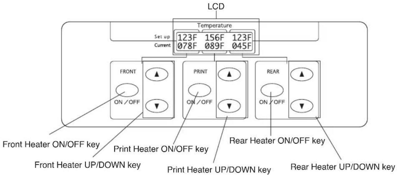
■ Functions of LCD, LEDs and keys
| rebuN | e maN | |
| LCD | TNORF | Indicates the setting temperature and the current temperature of the front heater. When the main switch of the heater is turned off, it is urged to turn on the main switch. When the front heater is turned off, "OFF" is indicated. |
| RPN | Indicates the setting temperature and the current temperature of the print heater. When the main switch of the heater is turned off it is urged to turn on the main switch.When the print heater is turned off, "OFF" is indicated. | |
| REAR | Indicates the setting temperature and the current temperature of the rear heater. When the main switch of the heater is turned off, it is urged to turn on the main switch.When the rear heater is turned off, "OFF" is indicated. | |
| key | FRONT ON/OFF key | Turns on/off the front heater. |
| FRONT UP key | Increases the setting value for the front heater. | |
| FRONT DOWN key | Decreases the setting value for the front heater. | |
| PRINT ON/OFF key | Turns on/off the print heater. | |
| PRINT UP key | Increases the setting value for the print heater. | |
| PRINT DOWN key | Decreases the setting value for the print heater. | |
| REAR ON/OFF key | Turns on/off the rear heater. | |
| REAR UP key | Increases the setting value for the rear heater. | |
| REAR DOWN key | Decreases the setting value for the rear heater. | |
Dryer 64 (Option)
The dryer 64 dries the output media.
Roll Cover 64 (Option)
Protects paper roll from dust.
Exhaust Attachment (Option)
Mounts an exhaust gas pipe to the printer or the drying device.
PS RIP (PhotoPrint 4 DX) (Option)
PS RIP (PhotoPrint 4 Server) (Option)
RIP software for the IP-6600.
This section explains the messages shown on the LCD and outlines menu operations.
Messages on the LCD
(1) Initialization display
The printer is being initialized.
Booting

INITIALIZING
WAIT A MOMENT
*: When the system starts normally, both controllers go online and enter idle mode automatically.
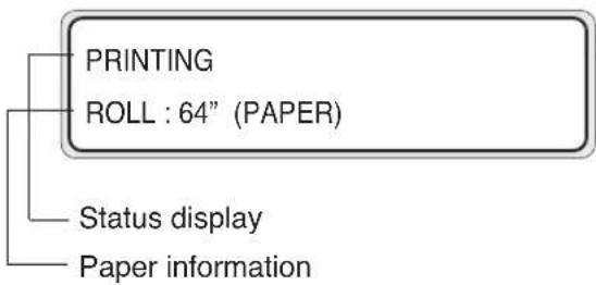
(2) Online state (idle mode) display
The printer can receive data from the computer.
PRINT READY
ROLL : 64" (PAPER)
Status display
Paper information
*: When the ENTER key is pressed in the menu mode, "CLEANING" menu appears.
(3) Online state (print mode) display
The printer is printing.
flowchart
graph TD
    A["PRINTING"] --> B["ROLL : 64" (PAPER)"]
    C["Status display"] --> D["Paper information"]
(4) Online state (print pause mode) display
The printer is paused.
- Print stop and resume
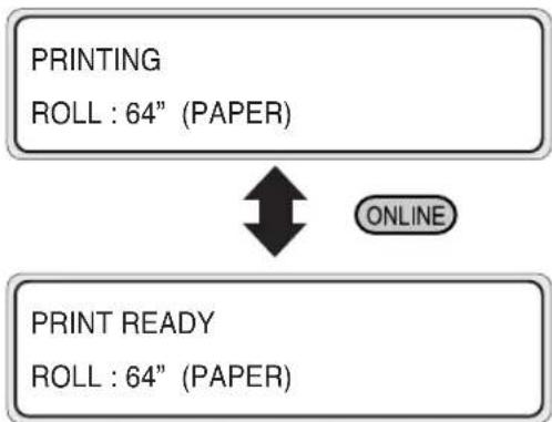
flowchart
graph TD
    A["PRINTING\nROLL : 64" (PAPER)"] --> B["PRINT READY\nROLL : 64" (PAPER)"]
    B --> C["ONLINE"]
The ONLINE LED flashes.
Press the ENTER key in the print pause mode to start the head cleaning.
- Print cancel (end)
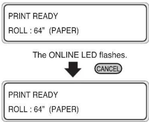
flowchart
graph TD
    A["PRINT READY\nROLL : 64" (PAPER)"] --> B["The ONLINE LED flashes."]
    B --> C["CANCEL"]
    D["PRINT READY\nROLL : 64" (PAPER)"] --> D
(5) Online state (print information mode) display
Paper total count and ink removing amount are displayed.
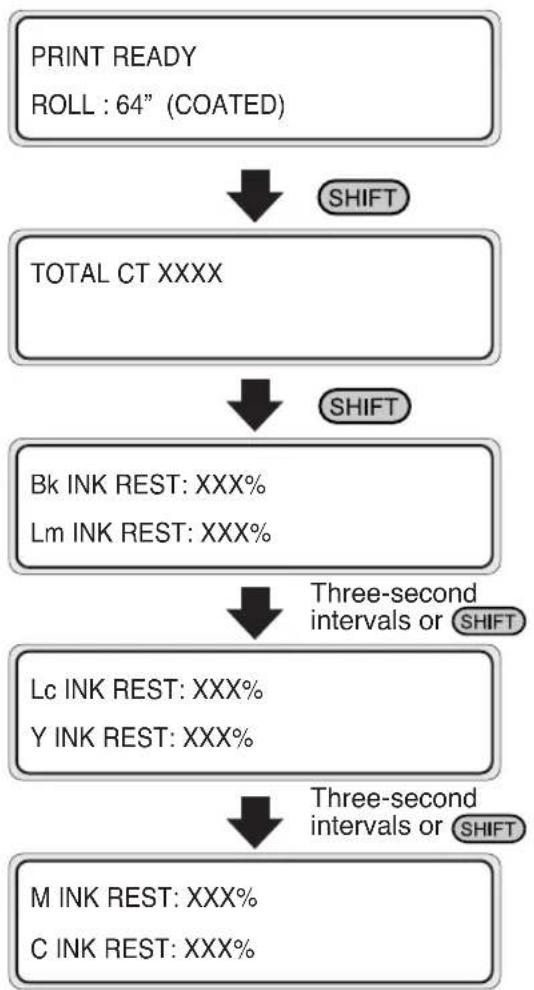
flowchart
graph TD
    A["PRINT READY\nROLL : 64" (COATED)"] --> B["SHIFT"]
    B --> C["TOTAL CT XXXX"]
    C --> D["SHIFT"]
    D --> E["Bk INK REST: XXX%\nLm INK REST: XXX%"]
    E --> F["Three-second intervals or SHIFT"]
    F --> G["Lc INK REST: XXX%\ny INK REST: XXX%"]
    G --> H["Three-second intervals or SHIFT"]
    H --> I["M INK REST: XXX%\nC INK REST: XXX%"]
Then, the printer returns to online idle mode.
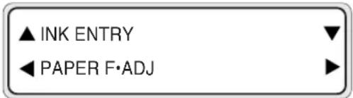
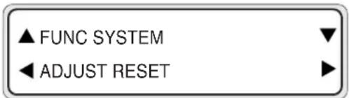
(6) Offline (menu mode) display
Menus can be operated in offline mode.
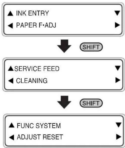
flowchart
graph TD
    A["▲ INK ENTRY\n◀ PAPER F·ADJ"] --> B["SHIFT"]
    C["▲ SERVICE FEED\n◀ CLEANING"] --> D["SHIFT"]
    E["▲ FUNC SYSTEM\n◀ ADJUST RESET"] --> D
*: ▲ ▼ ◀ and ▶ are access keys to menus.
*: When the ENTER key is pressed in the menu mode, "CLEANING" menu appears.
(7) Shutdown state display
The printer is shutting down.

Here, the function added in V2.00 as a firmware version checking method is described.
F/W Version Checking Method
(1) Select the OFFLINE mode. (Press the ONLINE)
(2) Press the key to display "SYSTEM".
(3) Select "SYSTEM" with the ▼ key, and then press the ▼ or ▲ key to display the firmware version.

(4) The F/W version can be checked.
X.XX is the F/W version.
Added Functions in V2.00
| 1 | History print | The function that prints the maintenance history was added. |
| 2 | Paper feed adjustment | During the online print, the paper feed adjustment correction value can be changed temporarily with keys. ▲ |
| 3 | Media entry | The registered media information can be copied to a new area. |
| 4 | Waste ink value saving | The mode that saves the waste ink quantity during auto cleaning was added. |
| 5 | Manual heater ON function | The function that turns on the heaters even before the data is received to save the waiting time until each heater temperature becomes the set value. |
Section 2 Basic Operations
Contents of this section
Connecting with Computer
System configuration (connection example)
Connection procedure
Turning the Power On/Off
Turning the Power On
Turning the Power Off
Replacing the Paper Roll
Installing Paper Roll in the Printer
Removing the Paper Roll from the Printer
Replacing Paper Roll with Another
Replacing Empty Paper Roll
Replacing Jammed Paper Roll
Installing/Removing Cut Sheet in/from the Printer
Paper Feed Adjustment Correction Value Setting
Replacing Ink Cartridges
Ink Cartridge Replacement Procedure
Replacing Empty Ink Cartridge
If an Ink Cartridge Is Not Installed
Replacing Cartridges during Printing
If an Ink Cartridge Is Not Detected
Replacing the Waste Ink Bottle
Waste Ink Bottle Replacement Procedure
If the Waste Ink Bottle Is Full
If the Waste Ink Bottle Is Not Installed
Head Cleaning "CLEANING"
Paper Feed "FEED"
Using the Origin Point Setting Function
Installing Paper on Winder
Changing Heater Control Setting Temperature
Using the Media Pressure Alternation Lever
Using the Head Up/Down Lever
Using the Media Edge Guard
Using the FAN Guard Slide Lever
Using the Print Pause/Restart and Cancel Keys
Inspection & Maintenance
This section only shows system configurations and cable connection procedure.
System configuration (connection example)
The following connection is possible.
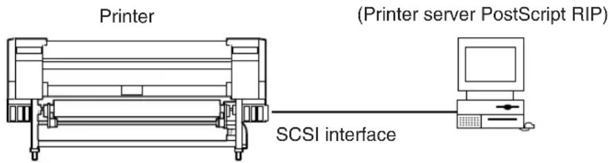
Connection procedure
Connect a cable as follows:
1 Turn the printer and the computer OFF.
NOTE
- When the printer is connected with the computer, turn the printer ON, and then turn the computer ON. To turn the system OFF, turn the computer OFF, and then turn the printer OFF.
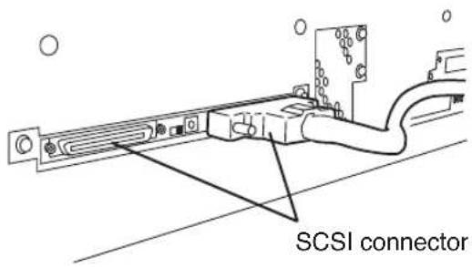
2 Connect a SCSI cable to a SCSI connector on the rear of the printer.
(It can be connected to any one of two SCSI connectors.)
NOTE
- Use a dedicated SCSI cable (68-68-pin, 6 m). If using a cable except the specified one, the printer can not satisfy FCC and CE regulations.
3 Set the ID switch on the rear of the printer.
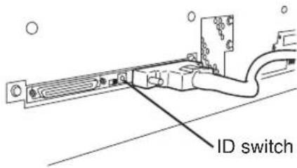
Set the ID number with a small normal driver, etc. (Initial ID value: 4)
NOTE
- The ID number must not be unique in the SCSI chain. (Initial setting: 4)
4 Set the terminator on the rear of the printer to ON or OFF.
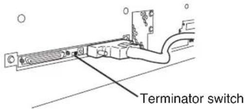
The printer has the SCSI terminator ON/OFF function. If the external terminator is not used and the printer is a terminating device in the SCSI chain (only one SCSI connector is connected), set the terminator switch to ON. If the printer is not a terminating device, set it to OFF.
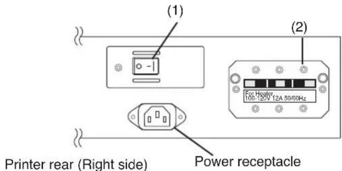
The power of the printer and the power of the heater are separated.
The printer has two power switches as follows.
(1) Printer switch
(2) Power ON/OFF switch
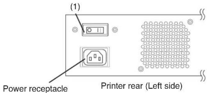
The printer is turned ON by turning the printer switch ON.
Afterward, turn the printer ON/OFF by the ON/OFF switch on the operation panel.
NOTE
- When the printer is connected with the computer, turn the printer ON, and then turn the computer ON. To turn the system OFF, turn the computer OFF, and then turn the printer OFF.
- T urn the computer ON after the printer becomes to the online state.
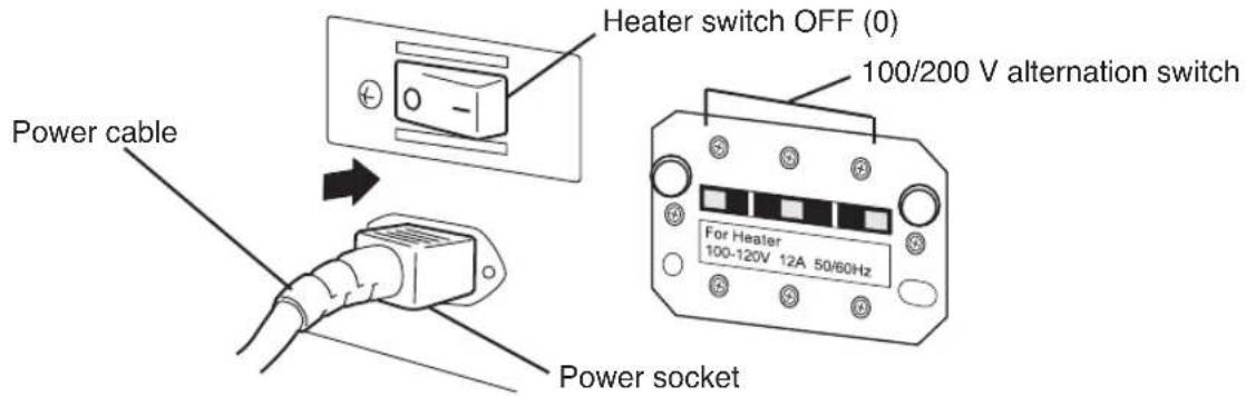
The heater has two power switches as follows.
(1) Heater switch
(2) 100/200 V alternation switch
Turning the Power On
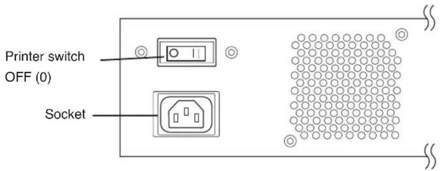
1 Turn OFF (0) the printer switch on the left rear of the printer, and plug one end of the supplied power cable into the socket of the printer. Insert the other power plug of the cable into an electrical outlet.
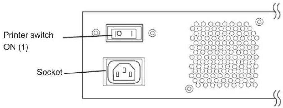
2 Turn ON (1) the printer switch on the left rear of the printer.
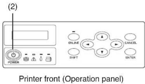
3 Turn ON the power ON/OFF switch on the operation panel.
When the switch is turned ON, a power-on self-diagnostic test is performed and the following message appears on the LCD on the operation panel.
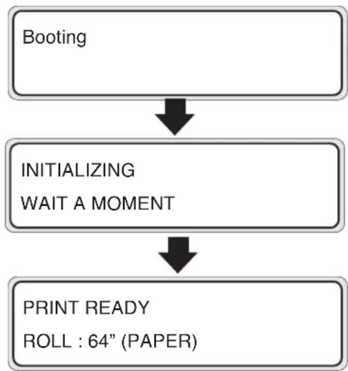
flowchart
graph TD
    A["Booting"] --> B["INITIALIZING WAIT A MOMENT"]
    B --> C["PRINT READY ROLL : 64" (PAPER)"]
If a 64" paper roll is used
The heater control panel is displayed by turning the printer power ON.
However, turn the heater power ON to use the heater.
When the heater power is turned OFF, the following message is displayed on the heater control panel.
TURN ON
THE HEATER
NOTE
- Turn OFF the printer while "PRINT READY" is displayed on the LCD panel except emergency.
Do not turn OFF the printer while "INITIALIZING" or "CLEANING" is displayed on the LCD panel to avoid drop of the ink and damage of the head.

- If the fan does not run or the operation panel lamp does not light when the printer switch and power ON/OFF switch on the operational panel are turned ON, the power supply may be faulty.
- If an error is detected during the self-diagnostic test at powering on, an error message appears on the LCD. See the Section 5, Troubleshooting and take an appropriate measure.
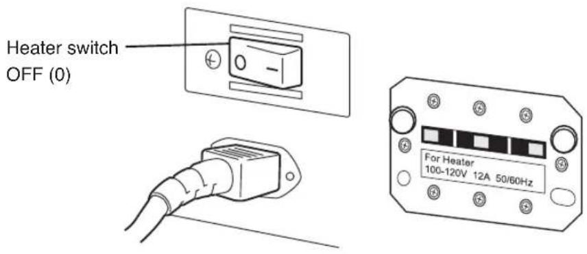
1 Turn OFF the heater switch on the right rear of the printer, and plug one end of the supplied power cable into the socket of the printer. Insert the other power plug of the cable into an electrical outlet.
NOTE
- Do not use the other power cable than specified in this printer.
- Verify that the supplied power cable meets the local AC power supply specifications.
- Verify that the 100 / 200 V alternation switch settings meets the local AC power supply specifications.
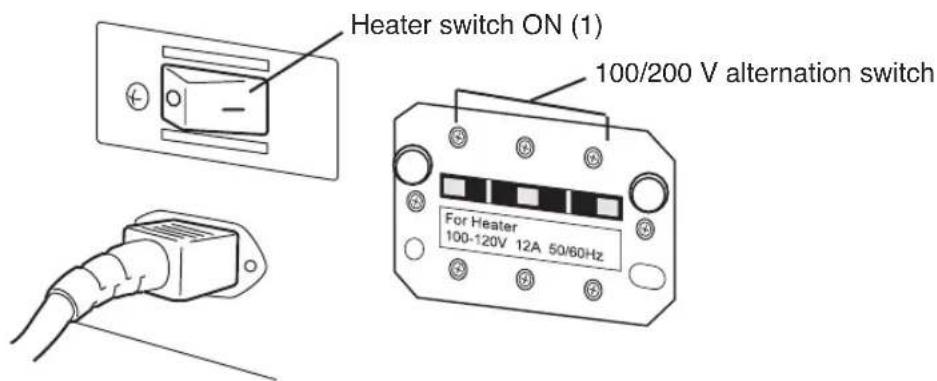
2 Turn ON the heater switch on the right rear of the printer to turn the heater ON.
Turning the Power Off
1 Turn OFF the power ON/OFF switch on the operation panel for a couple of seconds.
SHUTDOWN
WAIT A MOMENT
The above message is displayed on the LCD to indicate that a shutdown process is in progress. After the process ends, the power is turned OFF.
If the power off state lasts for a short time, you may turn the power off, skipping the fill cap operation by pressing the power ON/OFF key while pressing the CANCEL key.
Performing the fill cap operation is recommended.
CAUTION
- The printer switch on the rear of the printer should be used only when the printer is turned OFF completely in order to move it, connect it with a computer, install or maintain its parts.
- T turn the power ON/OFF switch OFF, wait for at least ten seconds, then turn it ON again.
- The printer performs fill cap operation to keep the good head condition at first 20 hours after print wait state and every 3 days.
It is recommended to keep the printer ON.
1 The heater power is also turned OFF by turning OFF the ON / OFF switch on the operation panel. Therefore, the heater switch turning OFF operation is not necessary in the normal use.
NOTE
- Use the heater switch on the right rear of the printer only when turning the printer OFF completely for transferring, installing, and maintenance service of the printer.
This section describes how to install a paper roll in the printer, and remove it from the printer.
A paper roll is replaced in the following three cases:
- If a paper roll is replaced with another
- If it is replaced when it runs out
- If it is replaced when it jams
A paper replacement procedure in each case is explained below:
Installing Paper Roll in the Printer
1 Open the rear cover and slide the media edge guards to the both edge of the platen.
NOTE
- Set the media edge guard after completion of the paper roll replacing. (See page 2-59, 60)
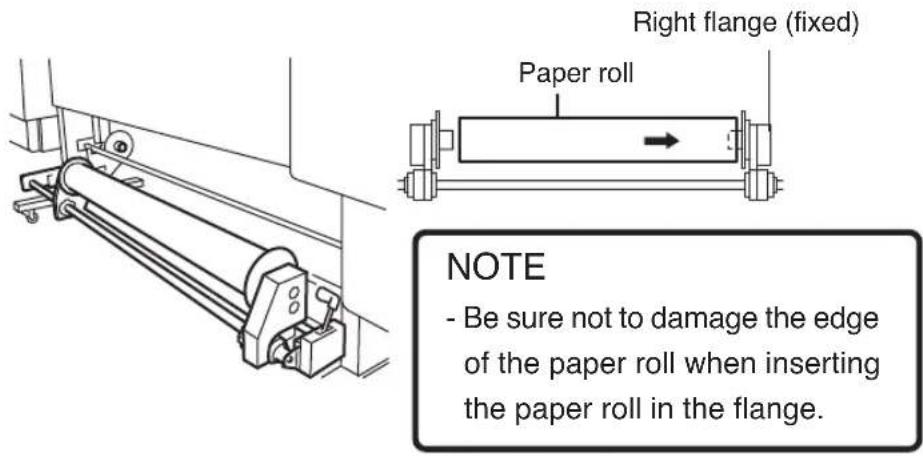
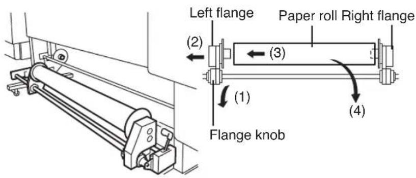
2 Insert the paper roll in the paper roll right flange (fix side).
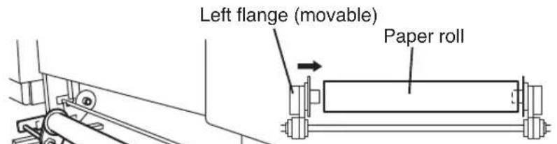
3 Slide the left flange (movable side) and put it into the paper roll.

CAUTION

Be sure not to catch your finger in the rail of the flange.
4 Tighten the left flange knob securely. Pull the winder sensor lever to front side.
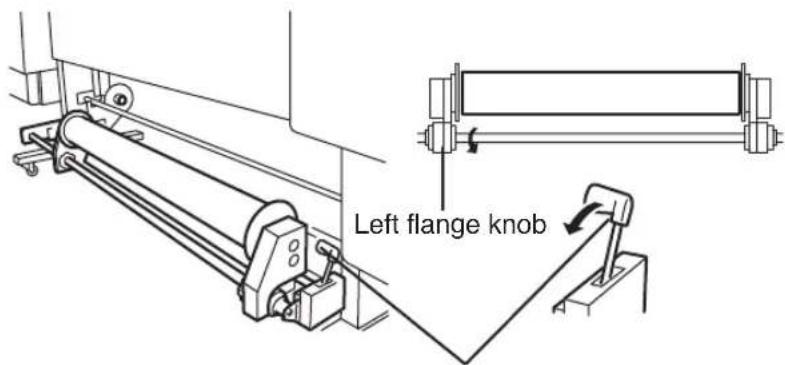
Winder sensor lever
5 Lift the pressure roller up/down lever.
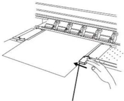
6 Feed the paper until a buzzer sounds from the paper feeder.
Feed the paper until an edge of the paper goes out 200 mm or more from the paper outlet.
(Paper setting direction)
NOTE
- Paper may stick to the paper feeder and is hard to set due to operational condition especially low humidity. In such a case, float paper from the paper feeder and set paper to the paper feeder by holding both edges of the paper.
- Be sure not to hit the edge of the paper roll by the rear cover.
- Be sure that the media edge guard is not set under the paper. (See page 2-52 Using the Media Edge Guard.)
7
When feeding a paper roll, hold it at the center and rewind the flange to take up the slack in the paper. The guide line on the printer is no more than a guide line. Install paper roll on the printer in a straight line against the paper roll.
The paper roll should not be inserted in the right of the perforated line.
If the paper roll is inserted in the right of the perforated line, adjust the flange position.
natural_image
Line drawing of a printer or printer with no visible text, numbers, or symbols8
Push down the pressure roller up/down lever.
Perform operations according to the guidance message shown on the LCD.
9
Confirm the media edge guard setting again.
Confirm whether the media edge guard does not goes down of the paper.
CHECK EDGE GUARD
*OK?
Confirm the position of the media edge guard and press the ENTER key.
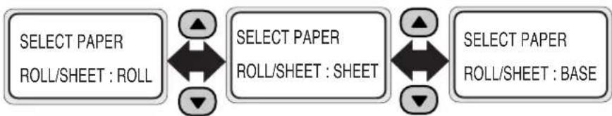
10 Select either paper roll or cut sheet.
flowchart
graph LR
    A["SELECT PAPER\nROLL/SHEET : ROLL"] --> B["SELECT PAPER\nROLL/SHEET : SHEET"]
    B --> C["SELECT PAPER\nROLL/SHEET : BASE"]
Select ROLL PAPER, CUT SHEET, or BASE with ⬆ or key.
(See Page 2-45 "Using the Origin Point Setting Function" about "BASE")
Press the ENTER to change setting.
Press the DANCED to leave the setting as it is.
11 Select a paper type.
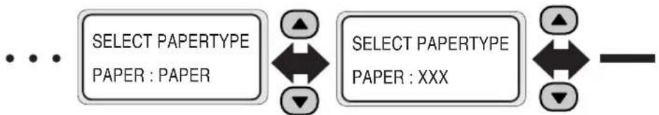
flowchart
graph LR
    A["SELECT PAPERTYPE<br>PAPER : PAPER"] --> B["←"]
    B --> C["SELECT PAPERTYPE<br>PAPER : XXX"]
    C --> D["←"]
Select paper type with ♠ or key ▼
Press the ENTER to change setting.
Press the CANCE to leave the setting as it is.
(When registering a new paper type)
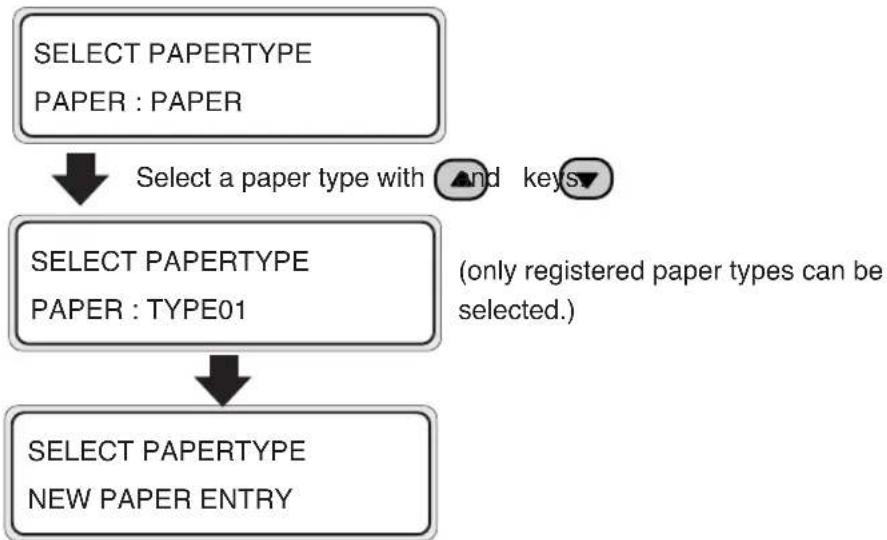
flowchart
graph TD
    A["SELECT PAPERTYPE<br>PAPER : PAPER"] --> B["Select a paper type with ▲ and keys▼"]
    B --> C["SELECT PAPERTYPE<br>PAPER : TYPE01"]
    C --> D["SELECT PAPERTYPE<br>NEW PAPER ENTRY"]
    note[" (only registered paper types can be selected.) "]
- Press key to enter to NEW PAPER ENTRY menu.
• Operation of the new paper entry is the same as operation for paper entry from ENTRY menu. (See section 3, Entry Menu) - Press kANCE return to SELECT PAPERTYPE menu.
12 The paper will be set automatically.
PREPARING PAPER WAIT A MOMENT

- If it is ended normally, return to offline or online state.
- If abnormal end occurs, an error message will be displayed.
Go back to 1.
13 Determine the position of movable fan.
After the paper setting operation finished, adjust the position of the fan guard slide lever at the rear of the printer. (See "Using the fan guard slide lever" (P.2-60).)
natural_image
Technical line drawing of a mechanical assembly with a hand operating a workpiece (no text or symbols present)Fan guard slide lever
Removing the Paper Roll from the Printer
1 Lift the pressure roller up/down lever.
2 Loose the left flange knob, pull out the paper roll from the flange, and remove the paper roll from the printer.
Replacing Paper Roll with Another
1 Put the printer offline. (Press the OKIME)
▲ INK ENTRY

PAPER F·FDJ

2 Press the Key and press the key ENTER
LIFT LEVER
3 Replace the paper according to the "Installing Paper Roll in the Printer" and "Removing it from The Printer."
Replacing Empty Paper Roll
1 A message appears on the LCD.
LIFT LEVER
SET PAPER
2 Replace the paper according to the "Installing Paper Roll in the Printer" and "Removing it from the Printer."
Replacing Jammed Paper Roll
See the Cleaning Paper Jam in Section 5, Troubleshooting.
Installing/Removing Cut Sheet in/from the Printer
Install/Remove the cut sheet in/from the printer referring to the procedures for the paper roll.
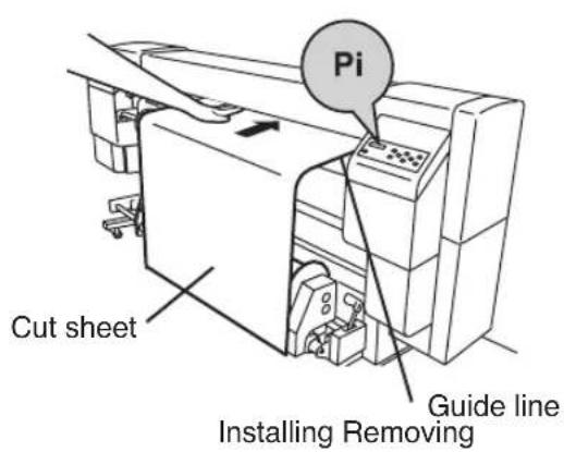
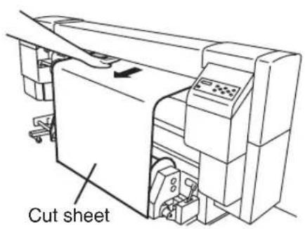
NOTE
- When installing the cut sheet in the printer, set the cut sheet using the guide line.
Paper Feed Adjustment Correction Value Setting
1 Set the paper of width larger than A1 size and length longer than 1m. (Press the
For the paper feed correction, obtain approximate paper feed adjustment correction value in the ROUGH mode, and set exact correction value in the DETAIL mode. One printing requires the paper length of 48 to 58~cm in the ROUGH mode, or 27 to 32~cm in the DETAIL mode. (Printing of paper feed adjustment pattern can be cancelled by pressing the CANCEL
NOTE
- If you use the tension winding, be sure to set the paper feed adjustment correction value in the tension winding mode.
- Longer print length is required in the tension winding mode.
2 Set the printer to OFFLINE mode. (Press the ONLINE key)
▲ INK ENTRY
◀ PAPER F·ADJ


3 Press the key, and then the key/NOR display a paper feed adjustment pattern.
FEED PATTERN
*ROUGH (NORMAL)
Select the print mode you usually use for the paper to which the paper feed adjustment correction value is set.
Selectable print modes are Standard, High Quality, High Density, High Speed, and Draft.
Select the paper feed adjustment pattern "Standard" if adjusting the high speed mode.
4 Press the ▼key to select the ROUGH print mode, and press the EKEYS
FEED PATTERN
*OK?
5 If you press the key the paper feed adjustment pattern "ROUGH" is printed.
The paper feed adjustment pattern "ROUGH" is printed in the selected print mode.
FEED PATTERN
*EXECUTING
6 From the printed result, select approximate paper feed adjustment correction value.
As nine patterns are printed in steps of 0.25% in a range of 99.00% to 101.00%, select approximate correction value.
7 Press the key, and then the key to display the entered correction value of paper feed adjustment.
FEED ADJUST
*099.80%
8 Enter the paper feed adjustment correction value, and press the EKEYR
Adjust the place with ◀, ▶ key and set a numeric value with ▼, ▲ key.
9 Press the key, and then the key to display the paper feed adjustment pattern.
FEED PATTERN
*ROUGH (NORMAL)
10 Press the ▼key to select a print mode for the DETAIL pattern.
FEED PATTERN
*DETAIL (NORMAL)
Select the same print mode as that for the ROUGH pattern.
11 Press the Ekey twice to print the paper feed adjustment pattern "DETAIL".
FEED PATTERN
*EXECUTING
12 From the printed result, select exact paper feed adjustment correction value.
As five patterns are printed for the entered correction value in steps of 0.06% in a range of -0.12% to +0.12%, select appropriate correction value.
13 Press the key, and then the key nor display the entered correction value of paper feed adjustment.
FEED ADJUST
*099.80%
14 Enter the paper feed adjustment correction value, and press the EKEVR
Adjust the place with ◀, ▶ key and set a numeric value with ▼, ▲ key.
15 Press the key, and then the key monitor display the paper feed adjustment pattern.
FEED PATTERN
DETAIL (NORMAL)
16 Press the ⓤ key to return to the initial OFFLINE state.
■ How to identify paper feed adjustment pattern Description is made in a case of black color.
If paper feed adjustment correction value is small 99.00% 100.25%
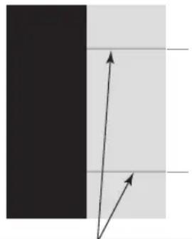
natural_image
Simple diagram showing two arrows pointing toward a vertical black bar and a horizontal gray bar, with no text or symbols present.Correction value is small if the joints of pass lines are overlapped (become dark) on these horizontal lines.
If paper feed adjustment correction value is appropriate 101.00%

natural_image
Two vertical color blocks, one black and one light gray, with no text or symbols.Correction value is appropriate if the joints of pass lines are not overlapped but uniform.
If paper feed adjustment correction value is large
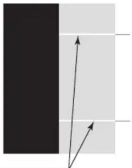
natural_image
Simple diagram showing two arrows pointing toward a vertical black bar on a light gray background (no text or symbols)Correction value is large if the joints of pass lines are separated (become light).
NOTE
- Set average value if appropriate correction value is different every head (every color). However, if an image to be printed has a preferential color, set correction value of that color.
- Set average value if appropriate correction value is different between left and right sides of the paper.
- Different appropriate correction value between left and right sides of the paper may be caused by the skew. Check again if the power is set correctly.
Change During Online Printing
[Additional functions available from V2.00 or later]
During the online printing, the paper feed adjusting value can be changed through the following operation.
PRINT READY
ROLL : 64" (PAPER)
Idle status
![SEIKO IP-6600 - [Additional functions available from V2.00 or later] - 1](/content/2026/06/1167840/images/b0ef63a44126d3c93f65df76ab1496ae2c13f37cbb5a18fb2a477b7dfd6254ff.jpg)
PRINTING
ROLL : 64" (PAPER)
Data receiving start
Data LED flashing
![SEIKO IP-6600 - [Additional functions available from V2.00 or later] - 2](/content/2026/06/1167840/images/8d9afaa6a3f72914b56ee8ecf22eddd1f808152c66c5c5f8aa17c627d1d67ea6.jpg)
Press the
![SEIKO IP-6600 - [Additional functions available from V2.00 or later] - 3](/content/2026/06/1167840/images/063ea0cdcfa1bd23f9f3369a6b52922fd43e01f90eb932dca34fb508ce4346f5.jpg)
key
![SEIKO IP-6600 - [Additional functions available from V2.00 or later] - 4](/content/2026/06/1167840/images/21dd7d6eefbf4d6b1cedbc32757835a08beca7ea73d11a2ddc7be52a2c246d01.jpg)
(Note: Disabled at the first scan and last scan)
FIN ADJ : 099. 80%
* 099.80%
Head print position adjustment
: 97.00% to 103.00%
- During "PRINTING" display, press the ▲ or ▼ to display currently selected paper feed adjusting value. On the right side of the first row, the value at the start of print is displayed and it does not vary until the print finished.
However, if a cleaning is executed in the MODE 2 in the midway of operation, the changed value is displayed after the cleaning.
- With the ▲ or ▼ key, increase (or decrease) the value in a step of 0.01%.
- When the value is changed, it is reflected in the printing.
- Numerical values you changed are registered and remain unchanged.
- Original display is restored if no key is operated for 3 seconds.
Head Print Position Adjustment
(1) Adjustment pattern print
Print the adjustment pattern print position of each head.
1 Select the OFFLINE mode. (Press the dwayne)
▲ INK ENTRY
◀ PAPER F·ADJ


2 Press the key twice to display "ADJUST".
3 Press the key and then the key to display "ADJUST PATTERN".
ADJUST PATTERN
TEST PRINT
4 Press the ⚙ key and select "HEAD ADJ1", and then press the ⚗ key
ADJUST PATTERN
* HEAD ADJ 1 OK
5 If the ENKEY is pressed, the "HEAD ADJ1" of adjustment patterns is printed.
ADJUST PATTERN
* EXECUTING
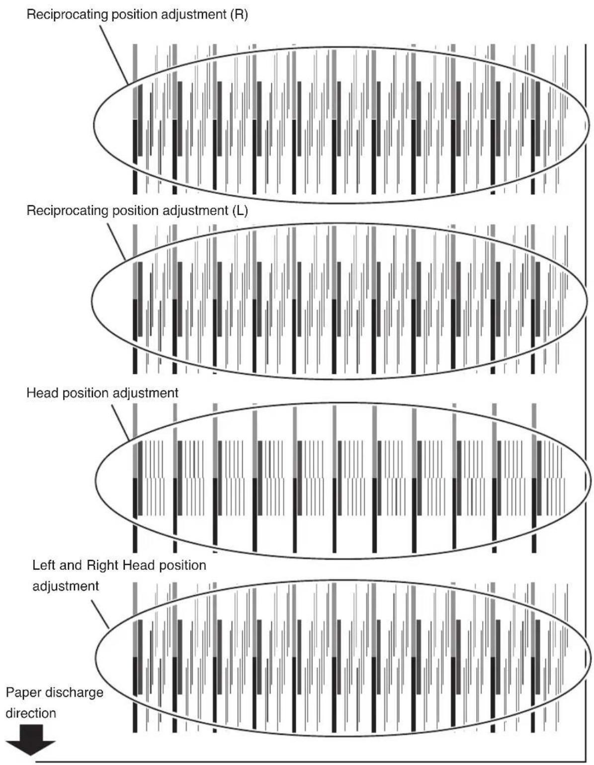
flowchart
graph TD
    A["Reciprocating position adjustment (R)"] --> B["Reciprocating position adjustment (L)"]
    B --> C["Head position adjustment"]
    C --> D["Left and Right Head position adjustment"]
    D --> E["Paper discharge direction"]
    style A fill:#f9f,stroke:#333
    style B fill:#f9f,stroke:#333
    style C fill:#f9f,stroke:#333
    style D fill:#f9f,stroke:#333
    style E fill:#f9f,stroke:#333
(2) Left and Right Head position adjustment
Adjusts the jetting position of nozzle.
Enter an adjustment value according to the head adjustment pattern.
1 Select "ADJUST", and then press the ⚙ key to display "L/R ADJ".
# L/R ADJ Bk
+00&A
2 Press the Key to display the head to be adjusted, and press the Key
# L/R ADJ Y
+00&A
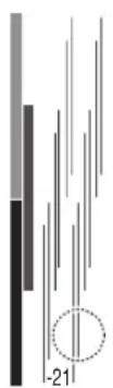
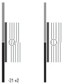
3 Of the left/right head position adjustment of the "HEAD ADJ1" patterns, enter a numeric value of the fittest pattern.
Select the digit to be entered between > and & with
keys, and change value with


Find a head adjustment sample where 2 lines with the same color are aligned. In case of Y-head illustrated in the right, for instance, -21 shows the sample where both are not aligned; -8 shows the sample where both are aligned. Accordingly, input -8 as an appropriate adjustment value.
4 Press the E key
(3) Head position adjustment
Adjusts the head position for the scanning direction on a Bk head basis.
Enter an adjustment value according to the head adjustment pattern.
1 Select "ADJUST", and then press the key to display "H-POS ADJ".
# H-POS ADJ Lm
+00&A
2 Press the ⓤ key to display the head to be adjusted, and press the ⓕ key.
# H-POS ADJ Lc
+00&A
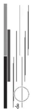
3 Of the main scan head position adjustment of the "HEAD ADJ1" patterns, enter a numeric value of the fittest pattern.
Select the digit to be entered between > and & with keys, and change value with ▲keys.
Find a head adjustment sample where the BK head-line and the head-position are aligned. In case of LC-head illustrated in the right, for instance, -21 shows the sample where both are not aligned; +2 shows the sample where both are aligned. Accordingly, input +2 as an appropriate adjustment value.
4 Press the KEYR
(4) Reciprocating position (Left) adjustment
Adjusts the head reciprocating position (Left).
Enter an adjustment value according to the head adjustment pattern.
1 Select "ADJUST", and then press the ⚙ key to display "I-POS (L) ADJ".
# I-POS (L) ADJ Bk
+00&A
2 Press the Key to display the head to be adjusted, and press the Key
# I-POS (L) ADJ Bk
+00&A
3 Of the reciprocating print position (Left) adjustment of the "HEAD ADJ1" patterns, enter a numeric value of the fittest pattern.
Select the digit to be entered between > and & with


keys, and change value with

For a hint on how to locate an appropriate adjustment value, refer to (2) Head Right and Left Adjustment on page 2-27.
4 Press the EKey
(5) Reciprocating print osition (Right) adjustment
Adjusts the head reciprocating position (Right).
Enter an adjustment value according to the head adjustment pattern.
1 Select "ADJUST", and then press the key to display "I-POS (R) ADJ".
# I-POS (R) ADJ Bk
+00&A
2 Press the ⓤ key to display the head to be adjusted, and press the ⓕ key
# I-POS (R) ADJ M
+00&A
3 Of the reciprocating head position (Right) adjustment of the "HEAD ADJ1" patterns, enter a numeric value of the fittest pattern.
Select the digit to be entered between > and & with


keys, and change value with

For a hint on how to locate an appropriate adjustment value, refer to (2) Head Right and Left Adjustment on page 2-27.
4 Press the KEYR
This section describes how to replace an ink cartridge.
Ink cartridges should be replaced in the following two cases:
- If ink has run out
- If an ink cartridge is not installed
The ink cartridge replacement procedure in the following each case is explained below.
NOTE
- Do not remove an ink cartridge under the following conditions.
Depending on the printer status, the ink spills within the ink box, causing a trouble. - In case that no power is supplied to the printer because of a power failure or printer breaker off.
- In case that an error other than ink end has occurred.
- If the cartridge in which the ink remains is replaced, do so in the offline mode.
(=> "Section 3 Ink Menu (5)")
- Make sure the upside and downside of the ink cartridge before installing.
Ink Cartridge Replacement Procedure
1 Open the ink cover.
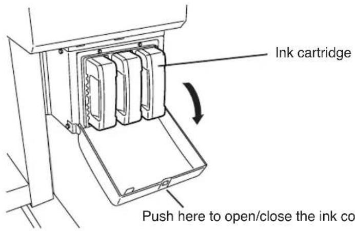
2 Remove an ink cartridge from the printer.
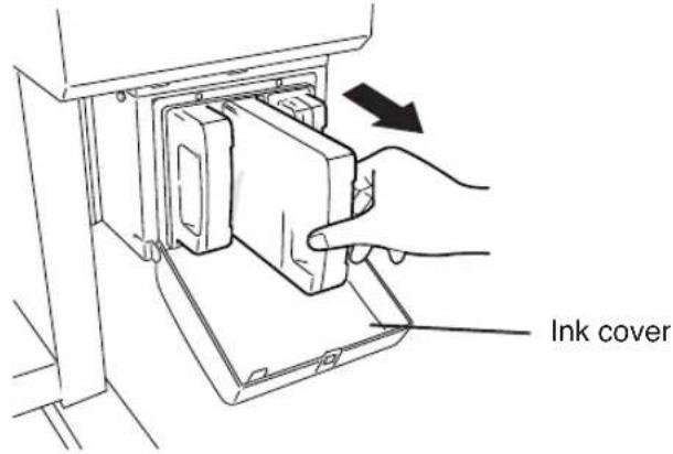
3 Insert a new ink cartridge into the printer.
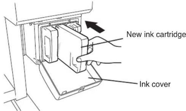
4 Close the ink cover.

5 End of ink cartridge replacement.
- If it is ended normally, return to offline or online state.
- If abnormal end occurs, an error message will be displayed.
Go back to 1.
- The printer continues to print when the ink remains in the sub-tank during replacing ink cartridge.
Replacing Empty Ink Cartridge
1 A guidance message appears.
OPEN L INKCOVER
CHANGE XX INK
XX: Ink name
Bk: BLACK
Lm: LIGHT MAGENTA
Lc: LIGHT CYAN
OPEN R INKCOVER
CHANGE XX INK
XX: Ink name
C: CYAN
M: MAGENTA
Y: YELLOW
2 Replace the ink cartridge according to the "Ink Cartridge Replacement Procedure."
If an Ink Cartridge Is Not Installed
1 The guidance message appears.
OPEN L INKCOVER
SET XX INK
XX: Ink name
Bk: BLACK
Lm: LIGHT MAGENTA
Lc: LIGHT CYAN
OPEN R INKCOVER
SET XX INK
XX: Ink name
C: CYAN
M: MAGENTA
Y: YELLOW
2 Replace the ink cartridge according to the "Ink Cartridge Replacement Procedure."
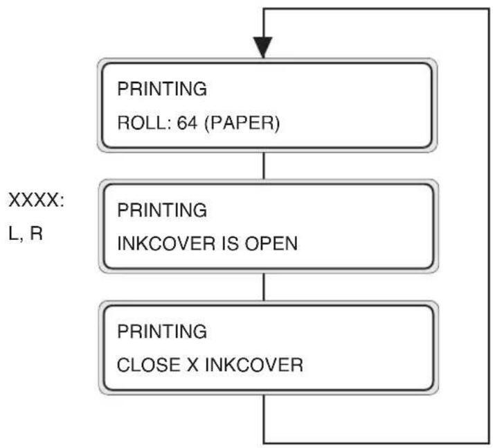
Replacing Cartridges during Printing
This unit enables you to replace the ink cartridges during the online printing without interrupting the printing operation. Accordingly, the guidance for ink replacement during the online printing is displayed on the second line of LCD. The following describes the guidance shown if the ink cover is opened during the online printing or if the ink in main cartridge is used up.
flowchart
graph TD
    A["PRINTING\nROLL: 64 (PAPER)"] --> B["PRINTING\nINKCOVER IS OPEN"]
    B --> C["PRINTING\nCLOSE X INKCOVER"]
    C --> D["XXXX:\nL, R"]
The guidance that prompts you to close the ink cover is displayed on the second line of LCD. The printing operation continues if the ink is present in the sub tank even though the ink cover is open. However, no ink is supplied to the sub tank because the ink cover is open.
If the ink in the sub tank is used up, the print pause mode is activated and the printing operation is interrupted until the ink cover is closed. Torecover from the interrupted state, close the ink cover and press the ONLINE key, and the pause mode is then cancelled and the print will restart.
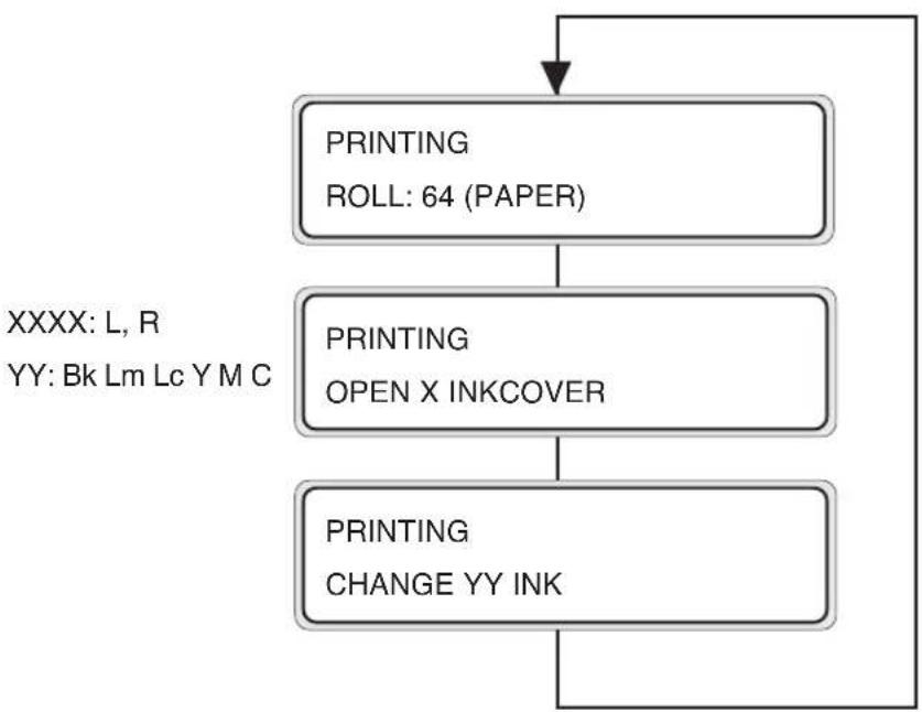
flowchart
graph TD
    A["PRINTING\nROLL: 64 (PAPER)"] --> B["PRINTING\nOPEN X INKCOVER"]
    B --> C["PRINTING\nCHANGE YY INK"]
    C --> A
The guidance that prompts you to replace the main cartridge is displayed on the second line of LCD. The printing operation continues until the ink in the sub tank is used up. During this time, if you replace the cartridge, the printing operation can continue without interrupting the printing operation.
If the main cartridge is not replaced even after the ink in the sub tank was used up, the print pause mode is activated and the printing operation is interrupted until the main cartridge is replaced.
To recover from the interrupted state, close the ink cover and press the ONLINE key, and the pause mode is then cancelled and the print will restart.

- The guidance concerning the ink replacement during the online printing is displayed on the second line of LCD, same as the guidance mentioned above.
Respective recovery methods are same as usual trouble-shooting methods.
If an Ink Cartridge Is Not Detected
1 The guidance message appears.
OPEN L INK COVER
CHECK XX INK
XX: Ink name
Bk: BLACK
Lm: LIGHT MAGENTA
Lc: LIGHT CYAN
OPEN R INKCOVER
CHECK XX INK
XX: Ink name
C: CYAN
M: MAGENTA
Y: YELLOW
2 Replace the ink cartridge according to the "Ink Cartridge Replacement Procedure."
This section describes how to replace a waste ink bottle.
The waste ink bottle should be replaced in the following two cases:
- If the waste ink bottle is full
- If the waste ink bottle is not installed
The waste ink bottle replacement procedures for these cases are explained below.
NOTE
- Do not replace the waste ink bottle during printing.
Waste Ink Bottle Replacement Procedure
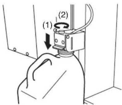
1 Loosen the knob and lift up the lever from the waste ink bottle.
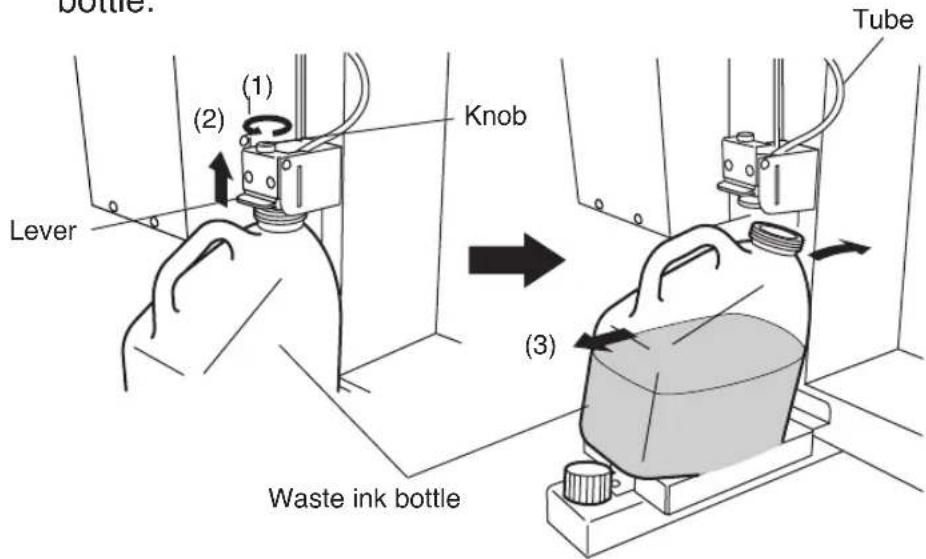
2 Wait for a while to drop the remaining ink into the ink tube.
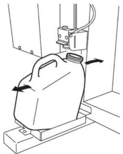
3 Take out the filled waste ink bottle from the printer, and securely cap the waste ink bottle to replace with a new one.
4 Wipe up the spilt ink into the waste ink bottle unit.
5 Lift the lever and mount a new waste ink bottle.
natural_image
Line drawing of a container being placed on a platform with directional arrows indicating movement (no text or symbols)6 Drop the lever and insert the ink tube securely and tighten the knob.
7 The selection message of the waste ink counter setting (reset (clear)) will be displayed.

flowchart
graph LR
    A["#INK COUNT RESET\n*NO"] <--> B["#INK COUNT RESET\n*YES"]
8 Select "YES" and press the Key
If the Waste Ink Bottle Is Full
1 Replace the waste ink bottle according to the "Waste Ink Bottle Replacement Procedure."
NOTE
- Make sure visually whether or not the waste ink bottle is not full before using the printer.
2 The selection message of the waste ink counter setting (reset (clear)) will be displayed.
INK COUNT RESET
*NO

INK COUNT RESET
*YES
NOTE
- The waste ink counter is prepared for urging waste ink disposal with the error message when the waste ink is more than the specified amount by counting the used (waste) ink amount.
The waste ink counter can detect full of the waste simultaneously but cannot detect actual full state of the waste ink.
The counter counts up from the empty of the waste ink bottle. Always select “*YES” for the “INK COUTN RESET” menu when replacing the waste ink bottle with a new one. If not, the waste ink full counter cannot be only used effectively, but also the waste ink becomes full before generating warning and the waste ink may be spilt over.
3 Select “*YES” and press the EKEYR
If the Waste Ink Bottle Is Not Installed
1 A guidance message appears on the LCD.
BOTTLE ISN'T SET SET BOTTLE
2 Insert a new waste ink bottle into the printer and install the waste ink bottle cover.
→ See the step 3 of the Waste Ink Bottle Replacement Procedure.
3 The selection message of the waste ink counter setting (rest (clear)) will be displayed.
INK COUNT RESET
*NO

INK COUNT RESET
*YES
4 Select “*YES” and press the EKEY
1 Put the printer offline. (Press the ⓄNOVE)
▲ INK ENTRY

◀ PAPER F·ADJ

2 Press the key to display the CLEANING menu.
▲ INK ENTRY

◀ PAPER F·ADJ


SHIFT
▲ SERVICE FEED

CLEANING

3 Press the 🔊 key to enter the head cleaning menu.
# CLEANING
NORMAL
4 Press the Key
# CLEANING
* OK?
5 Press the ▲ key and ▼ key to select a cleaning option.
CLEANING
*NORMAL

CLEANING
*SLIGHT

CLEANING
*STRONG
6 Press the EKey
CLEANING
*BOTTLE OK?
7 Make sure that the waste ink bottle is not full, and then press the Ekey again.
CLEANING
WAIT A MOMENT XXX
XXX : Figure will be increased in about 10 seconds.
NOTE
- The cleaning takes several minutes.
8 When the cleaning is completed, the screen is returned to step 3 automatically.
# CLEANING
NORMAL
9 Press the Key to return to the original offline mode.
This section describes how to manually feed paper after printing.
1 Put the printer offline. (Press the OKEYE)
▲ INK ENTRY
◀ PAPER F·ADJ


2 Press the key to display the FEED menu.
▲ SERVICE FEED
CLEANING


3 Hold down the key.
PAPER FEEDING
While the key is kept pressed, the currently selected roll paper is fed. If a cut sheet is used, it is discharged.
4 When the key is released, paper feeding stops and the top screen returns to offline mode.
▲ SERVICE FEED
CLEANING


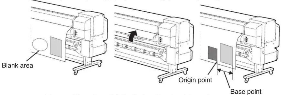
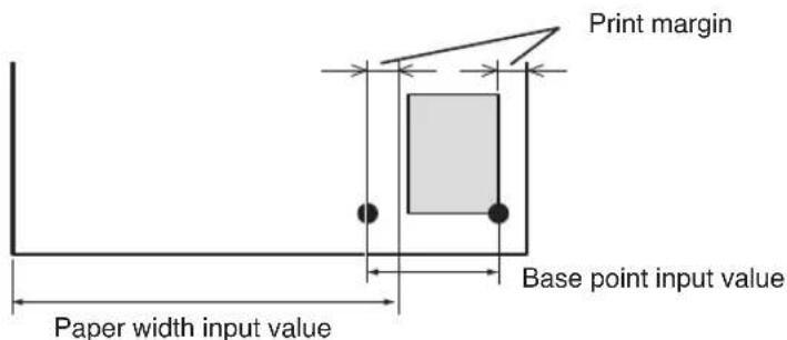
Using the Origin Point Setting Function
When printing a small size image such as a A4 size image on the 64-inch width paper, the large blank will be generated as the figure shows below.
In this case, rewind the print paper and set the print origin point to print an image on the blank area.
The print origin point setting at paper rewinding is called as “Origin Point Setting Function.”
(1st time printing) (Paper rewinding) (2nd time printing)
1 Lift the pressure roller up/down lever and rewind the paper.
SET PAPER
PUSH DOWN LEVER
Pressure roller up/down lever
natural_image
Mechanical assembly diagram showing a lever mechanism with no visible text or symbolsNOTE
- Rewind the paper after the paper is enoughly dried. If not, the 1st time printing image may be damaged.
2 Push down the pressure roller up/down lever.
Pressure roller up/down lever
3 Select "BASE" in the "SELECT PAPER" menu and press the EKEYR
SELECT PAPER
ROLL/SHEET: BASE
4 Input the paper width and press the
PAPER WIDTH
*1372 mm
The paper width detected at previous time is displayed. (Paper width input range: 290 to 1635 mm)
5 Input the base point (print offset value for paper width direction: origin point).
BASE POINT
*0000 mm
The base point set at previous time is displayed.
The previous setting value will be displayed.
The origin moves if either paper width or base point is set.
6 Select “\*Yes” or “No” of back feed operation.
PAPER FEED BACK
*NO
The area from the paper output sensor position to the print start position (the grid roller) becomes print dead area.

PAPER FEED BACK
*YES
The print dead area can be decreased by rewinding the paper for length between the paper output sensor and grid roller.
(20 to 30 mm from the front edge cannot be printed.)
NOTE
- Cut the edge of the paper so that it will be parallel to the guide line before installing the paper. If the edge of the paper is not parallel to the guide line, the front side of the print is cut, the platen is stained with ink, and the paper jam may be caused.
7 Select a paper type again.
SELECT PAPER TYPE
PAPER: TYPE01

ENTER
PREPARING PAPER
WAIT A MOMENT
NOTE
- When using the origin point setting function, keep front, right, and left margins sufficiently because the paper is rewinded manually.
- The paper width and base point settings cannot be saved.
- The origin point setting function can be used only for paper roll. This function cannot be used for the cut sheet.
A paper winder unit is built in the printer. It winds roll paper for storage without cutting it.
Use the paper winder unit as follows:
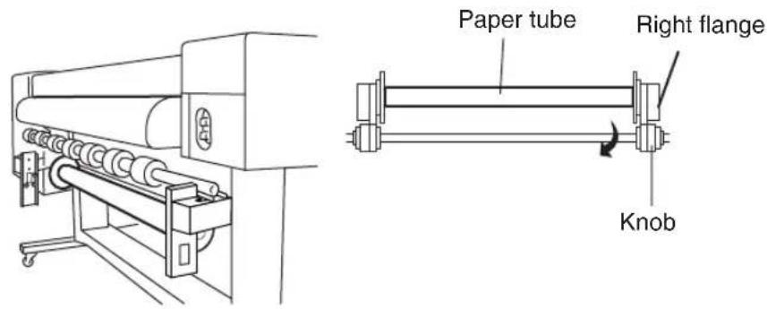
1 Prepare the paper tube and 1 m-lead paper of which paper width is the same as the paper's you will use.
Attach the lead paper on the paper tube.
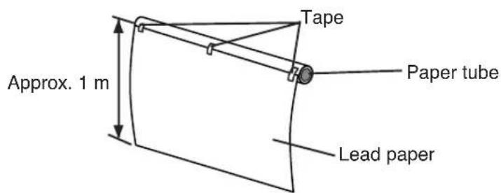
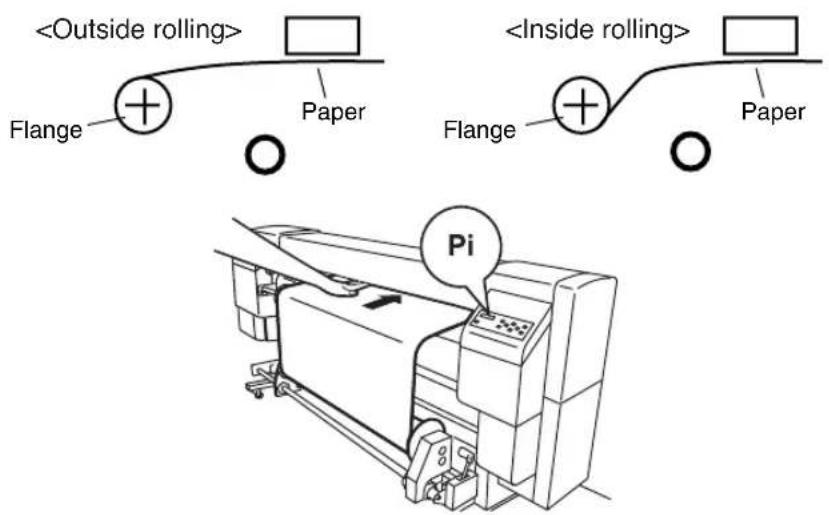
NOTE
- Pay attention to the direction of attaching tape on the winding side according to the winding direction setting (outer side rewind/inner side rewind).
- Attach the paper to the take out roller straightly to protect slanting feed.
- The paper tube width on the winding side must be same as the width of the rolled paper to be printed.
The use of larger width may cause a winding deviation.
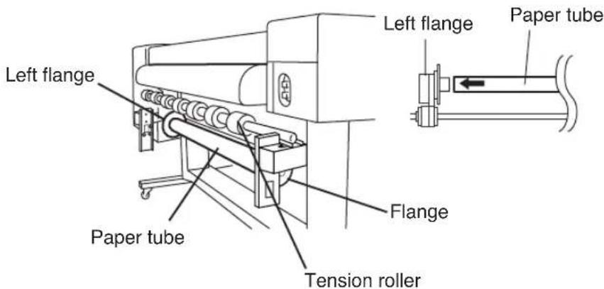
2 Insert the paper tube with the lead paper to the left flange.
3 Slide the right flange (movable side) and insert it into the paper tube.
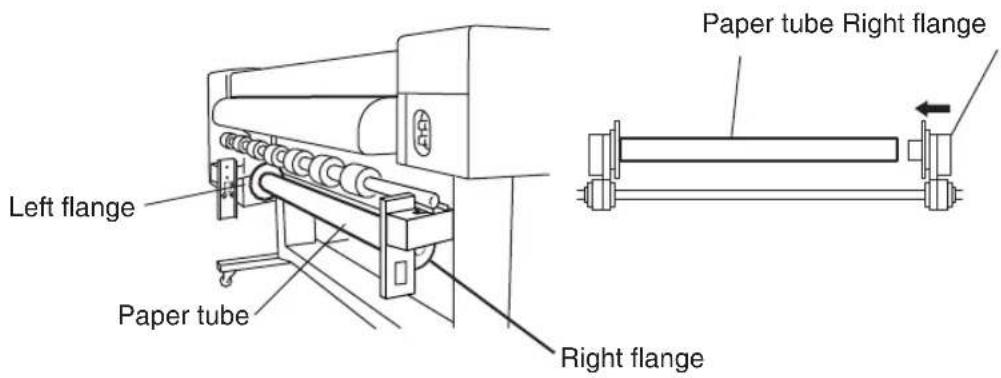
4 Tighten the right flange knob securely.
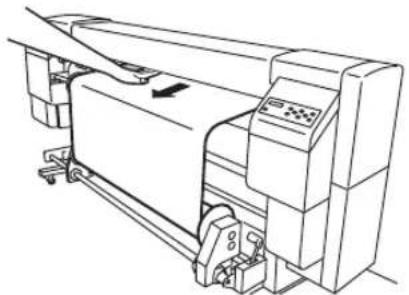
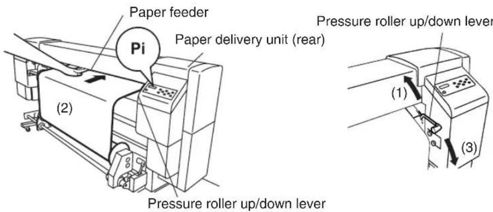
5 Lift the pressure roller up/down lever, insert paper from the paper feeder, push down the pressure roller up/down lever to set the paper, and feed paper by the Feed menu on the operation panel (see Section 3, Operation Panel Menu Operations (Feed Menu)) until the paper is wound.
6 Tape the edge of the paper on the lead paper at three positions: both sides and center.
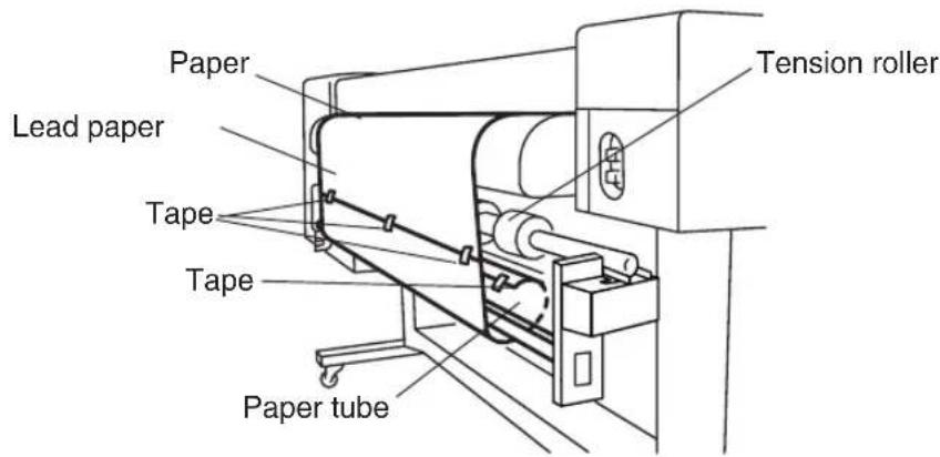
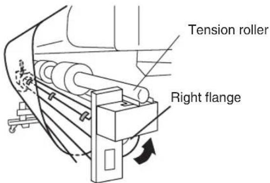
7 Manually turn the scroller flange in the direction of winding to wind the paper slightly.
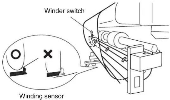
8 Check the positions of the paper and winding sensor, and install it.
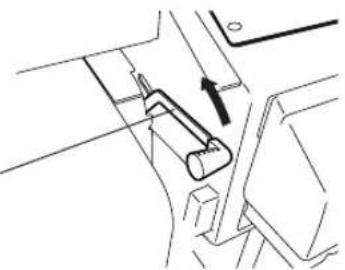
The winding unit supports two winding methods; tension winding and slack winding.
Generally, use the slack winding. If the slack winding does not work correctly, use the tension winding. Also, be sure to use the slack winding for glossy paper.
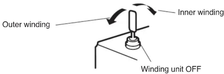
Also, inner winding and outer winding are available.
● Tension roller setting.
- Slack winding: Set the tension roller to the upper side.
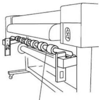
natural_image
Line drawing of a mechanical printing press machine with rollers and control panel (no text or symbols)Tension roller
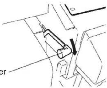
- Tension winding: Set the tension roller to the lower side.
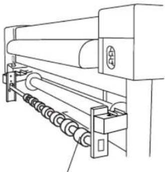
natural_image
Technical line drawing of a mechanical device with rollers and a roller assembly (no text or symbols)Tension roller
Slide seven tension rollers according to the paper width.
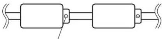
natural_image
Pure electrical circuit lines without any symbolsTo slide a tension roller, loosen three slotted head screws.
NOTE
- Do not change the order of seven tension rollers, as their outside diameters are different. Changing the order will cause a skew.
• Winding unit switch setting
Either internal winding or external winding can be selected.
When the winding unit is not used, turn the winding unit switch off.
NOTE
- Slacken the paper so that it passes inside the winding sensor.
- If the winding unit is not used, turn the winding unit switch off.
- When the paper roll for the winding unit nears the diameter of the winding unit's flange, remove the winding side paper roll and replace the paper tube with a new one.
If not so, a winding error may occur.
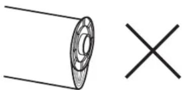
natural_image
Simple line drawing of a circular object with a cross mark, no text or symbols presentIn case that the paper roll for the winding unit exceeds the diameter of the winding unit's flange.
- When printing without using a winding unit, edge of paper or printing surface may be damaged or be folded due to contact with the winding sensor caused by winds. Fold the winding sensor, or handle the printing surface with care.
Changing Heater Control Setting Temperature
In normal use, temperatures of all heaters for the every selected media are preset automatically.
Therefore, ON/OFF setting and temperature setting for all heaters are not necessary.
Use the heater control panel only when the fine adjustment for the heater temperature is desired.
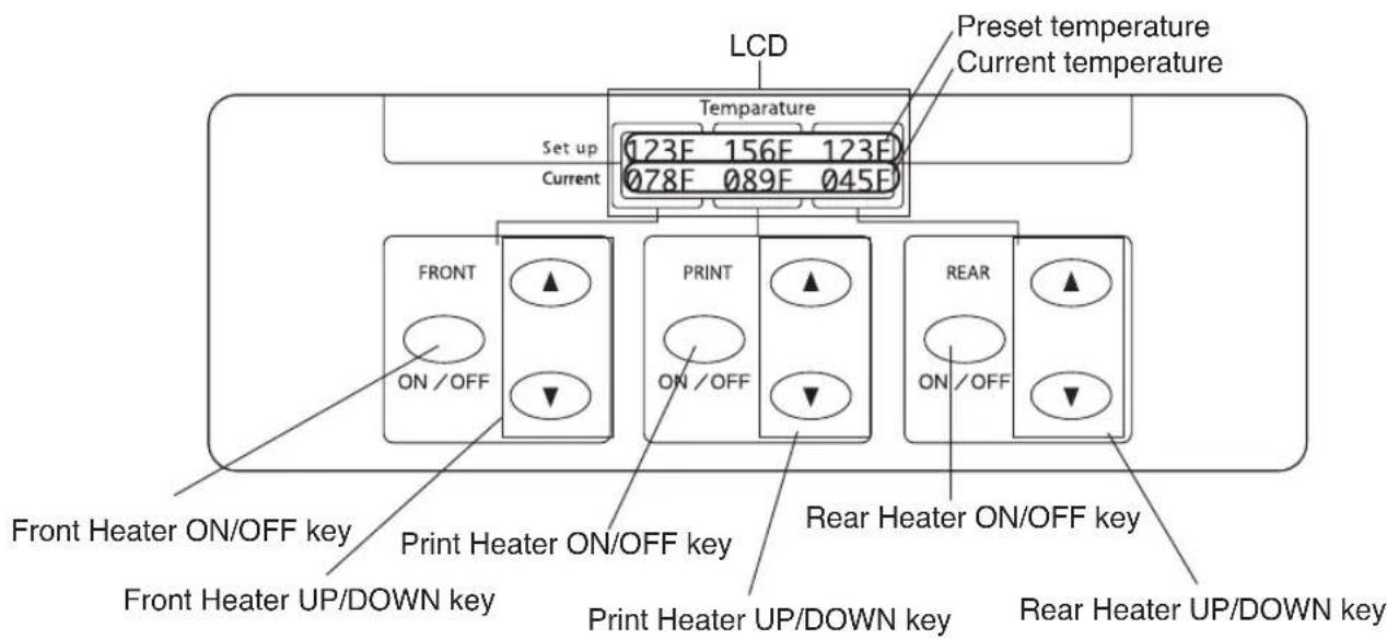
Set on/off and setup temperature of three heaters on the heater control panel.
- ON/OFF setting: Use ON/OFF key for each heater.
• T emperature setting: Use the up key or down key for each heater.
• LCD screen: (When the heater is turned ON)
• Upper line: Preset temperature for each heater - Lower line: Current temperature for each heater (When the heater is turned OFF)
• Upper line: "OFF" for each heater - Lower line: Current temperature for each heater
The preset temperature range is fixed to 15 °C to 55 °C.
■ Heater preset temperature by medium
The heater preset temperature for medium is listed in the table. Preset the heater temperature according to the media you use.
| muidelM | e terutarepmet p edomRhi | ||||
| FRONT | REAR | ||||
| Glossy vinyle oldc | Glossy | 45°C | 40°C | 45°C | 4aph bi-direction |
| Mat vinyle chrolide | Matte | 45°C | 40°C | 45°C | 4aph bi-direction |
| Banner | Banner | 45°C | 40°C | 45°C | 4aph bi-direction |
y
It is recommended that the front heater, the print heater and the rear heater be set to lower than 50 °C , 45 °C and 50 °C , respectively. When the print heater is set to higher than 45 °C , we recommend setting the head motion mode to "HIGHLIGHT."
NOTE
- When the print heater temperature is set to high, fixibility of the ink is improved, but paper wrinkle or mat print may be caused.
Adjust heater temperature according to the paper type and environmental temperature. - When the print heater temperature is set to high, the printer may print at low speed to ensure stable print quality.
- Set the front/rear heater temperature higher 5 °C than the print heater's.
Bad temperature balance between the front/rear heater and print heater may cause paper wrinkle.
■ Flow of heater temperature setting
(1) If the paper type is selected in setting the paper, the temperature initial value of each heater set for that paper is set on the heater control panel.
- If the temperature initial value has been set, the heater turns on. (Heating does not start yet.)
- If the temperature initial value is set to **, the heater turns off. (The set temperature display on the heater control panel becomes OFF.)
(2) If the print data are sent from the host (PC), either of the following operations is performed before the print starts.
A) If "Priority Setting (Heater)" set for the paper is "Data Priority"
- The temperature set with RIP (print data, job) overwrites the set temperature on the heater control panel, and the heating starts. (The heating does not start if the temperature set value is OFF.)
- If the temperature is not set with RIP (print data, job), the heating starts with the set temperature on the heater control panel.
B) If "Priority Setting (Heater)" set for the paper is "Panel Priority"
- The temperature set with RIP is ignored and the heating starts with the set temperature on the heater control panel.
(3) The print starts when the current temperature of front, print, and rear heaters all reaches the value exceeding "set temperature -2 °C", the print starts.
If the current temperature is higher than the set temperature, the print starts without waiting for the temperature to drop. Even after the print started, the temperature control is made so that the heaters keep the set temperature.
(4) During the printing, the temperature can vary while the printing is performed by changing the set temperature with the "TEMPERATURE UP/DOWN" key on the heater control panel.
Even after the print finished, the temperature changed in this section remains as "set temperature".
(5) Hence, the print job returns to step (2).
For the temperature initial value setting of front, print, and rear heaters, and the priority setting (heater), see Section 3 Entry Menu.

- The heaters operate under the condition displayed on the heater control panel, whatever means are used to set the temperature.
Using the Media Pressure Alternation Lever
Alternate the media gripping pressure of the paper transmission roller according to the media.
Generally, set the media pressure alternation lever to “normal pressure.” When media cannot be fed correctly due to skew, set the media alternation lever to “high pressure.”
Use the media pressure alternation lever to alternate the media gripping pressure (See the figure below).
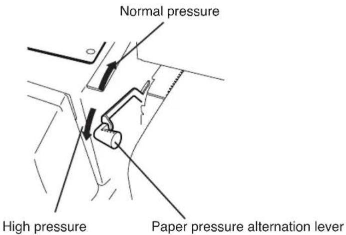
NOTE
- The shape of the lever groove is shown below.
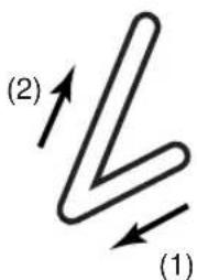
Pull the lever front and push up the lever for alternate the pressure from high to normal.
Alternate the head height according to the media you use. Use the head up/down lever for alternating the head height. (See the figure below)
1 Enter SERVICE menu and execute HEAD HEIGHT ADJ on the operation panel.
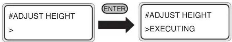
flowchart
graph LR
    A["#ADJUST HEIGHT"] -->|ENTER| B["#ADJUST HEIGHT"]
    B -->|EXECUTING| C["End"]
2 Open the cap cover and loosen the head fixing screws (2 pieces) with a screw driver.
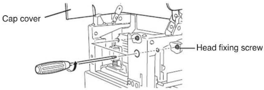
3 Alternate the height of the head with the head up/down lever.
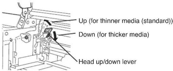
Generally, preset the head up/down lever up for glossy vinyle chloride and matted vinyle chloride, and preset the head up/down for banner and FF.
When the paper thickness is 0.5 mm or more, preset the head up/down lever up regardless of media type.
When the head is rubbed with the media due to media floating, preset the head up/down lever down even for the thinner media.
4 Tighten the head fixing screws (2 pieces).
NOTE
- When changing the height of the head, tighten the head fixing screws while pushing the head down softly with your hand.
- When the head height is changed, change head height setting (19) in ENTER menu.
- When the head height is changed, print gap may be occurred at reciprocating print. In that case, adjust the correction value for reciprocating print. (See (20) Reciprocating print position (Left) adjustment value, and (21) Reciprocating print position (Right) adjustment value in ENTRY nemu.)
Mount the media edge guard on the right and left media transmission path to protect the head from nap and curl of the media edge.
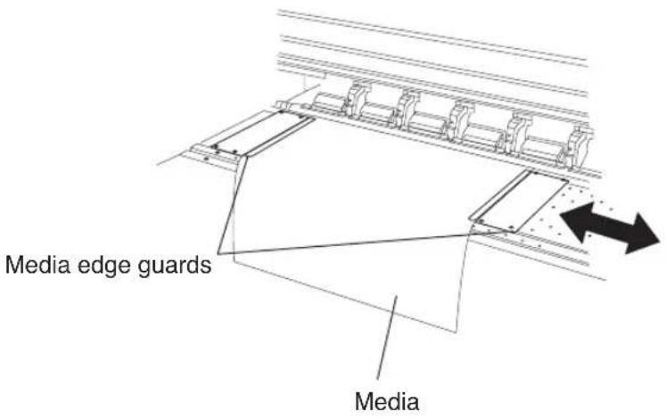
NOTE
- Preset whether or not the edge guard exists in the PAPER menu on the operation panel corresponding to the mounting the media edge guard.
The right and left margin of the print area will be changed according to the setting of the edge guard. - When using the media edge guard, right and left margin of the print area becomes 10 mm.
Using the FAN Guard Slide Lever
Cut suction of the FAN for unused area to protect the head from suction of the FAN.
Slide the FAN guard slide lever between 50 inch width and 64 inch width.
Set the FAN guard slide lever according to the paper width you use.
NOTE
- When setting the FAN guard slide lever for 50 inch width paper at 64 inch width paper printing, the paper cannot be passed.
- Do not move the fan guard slide lever during print. If the fan guard slide lever hits the paper, paper jam could be occurred.
- T o prevent a jam due to the skew feed, ensure a clearance of about 5mm between the arrow on the slide lever and the paper edge.
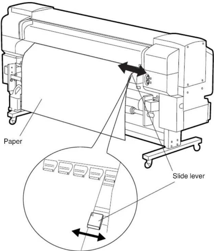
Using the Print Pause/Restart and Cancel Keys
Print pause/restart and print cancel are also available from the rear (paper outlet side) of the printer.
Print pause/restart and print cancel are available during checking the print condition from the paper outlet side.
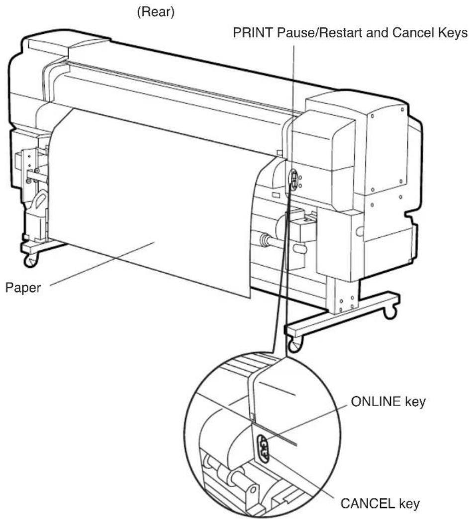
ONLINE key: Pause/Restart printing CANCEL key: Cancels printing
Operations of the ONLINE and CANCEL keys are the same as those of the operation panel's.
Regular inspection and maintenance by operators are described below.
■ Regular inspection and maintenance guide
The printer needs regular inspection and maintenance.
The table below lists all regular inspection and maintenance.
For details of each regular inspection and maintenance, see the page to be referred.
| Category Inspection/Maintenance | page to be referred | ||
| 1 | Daily inspection and maintenance | - Wiper Blade Cleaning- Wiper Sponge Cleaning- Capping Unit Cleaning- Waste Ink Bottle Disposal- S oft Head Cleaning- Test Print | 2-63 |
| 2 | Every one month inspection and maintenance | - H ead cleaning | 2-67 |
| 3 | When leaving the printer for a long time in power off state (more than 2 weeks) | - Service Clean | 2-67 |
| 4 | When returning the printer from a long time leaving (more than 2 weeks) | - H ead Wash- Ink charge after head washing | 2-68 |
| 5 | When returning the printer from a long time leaving (within 2 weeks) in power off state. | - H ead Wash- Ink charge after head washing | 2-69 |
| 6 | When leaving the printer in power off for more than one month | A service call error message will be displayed on the operation panel. Contact our service center. | 2-71 |
■ Daily inspection and maintenance
Perform the followings every day to ensure stable print quality.
(1) Wiper Blade Cleaning
(2) Wiper Sponge Cleaning
(3) Capping Unit Cleaning
(4) Waste Ink Bottle Disposal
(5) Soft Head Cleaning
(6) Test Print
NOTE
- Perform the above every day before print.
- Always use our specified cleaning liquid and cleaning swab.
Enter to the "SERVICE" menu and select "WIPE CLEANING" on the operation panel.
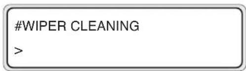
The wiper blade will come up for cleaning.
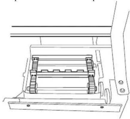
natural_image
Technical line drawing of a mechanical assembly with no visible text or symbolsOpen the rear cover and the wiper cover.
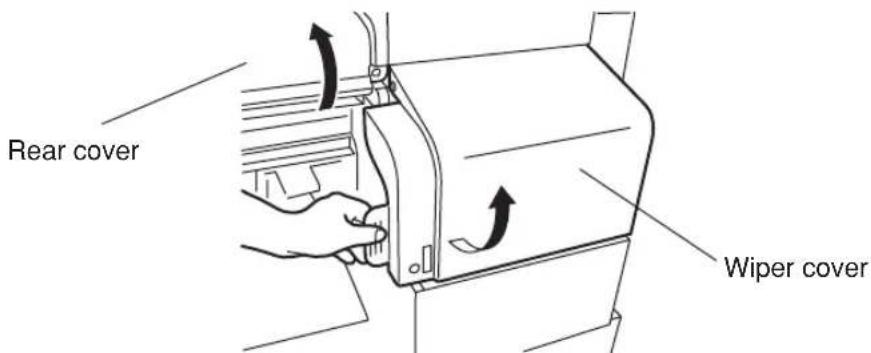
Check no dregs of the dried ink and no damage on the blades.
Clean the front and back of the blades with the cleaning swab infiltrated into the wiper cleaning liquid.
After completion of the cleaning, close the wipe cover and the rear cover to return the wiper to the position as it was.
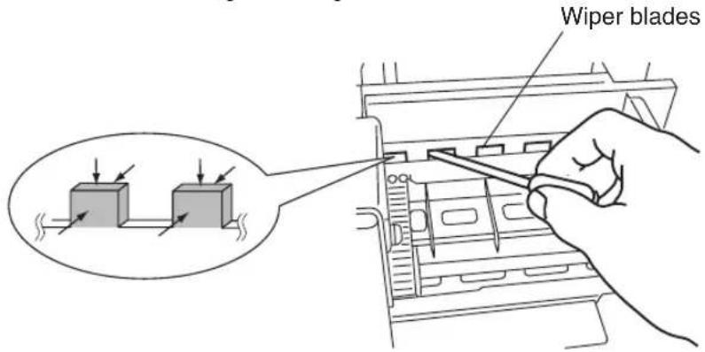
NOTE
- T ake extreme care not to allow the wiper cleaning liquid to attach to the parts other than wiper blades.
Attaching the wiper cleaning liquid to the belts or sensors may cause a trouble.
The wiper sponge has to be moistened.
Check the moisture of the sponge every day before printing.
Check whether the sponge is dried by pressing the dried swab on the sponge.
If the sponge is dried, moisten it with the wiper cleaning liquid.
Werecommend applying wiper cleaning liquid of one syringe to the wiper sponge every day.
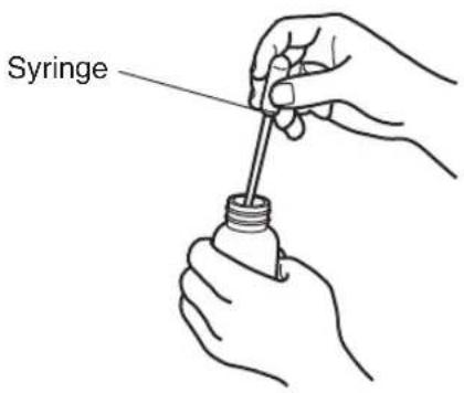
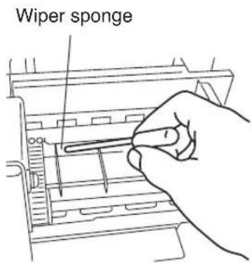
NOTE
- Take extreme care not to spill the wiper cleaning liquid on the parts other than the wire sponge.
Spilling the wiper cleaning liquid on the belts or sensors may cause a trouble.
Enter to the SERVICE menu and select "CAP CLEANING" on the operation panel.
CAP CLEANING
The head carriage will move to the wipe side and you can access easily to the capping unit.
Open the rear cover and cap cover. Wipe up the edge and periphery of the upper surface of all (six) caps carefully with the cleaning swab.
Clean he edge and periphery of the upper surface of the cap.
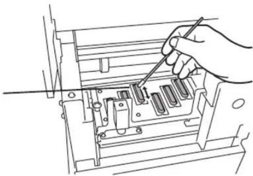
natural_image
Line drawing of a hand using a screwdriver to adjust internal components in a machine (no text or symbols)Close the cap cover and rear cover. The head carriage will return to the capping unit position (home position) automatically.
NOTE
- Do not leave the printer for long time in the condition that the head carriage is not on the capping unit.
Pour the waste ink into the proper container you prepared and make the waste ink bottle empty.
Enter to the “CLEANING” menu and select “SLIGHT” on the operation panel. (See page 2-42.)
Enter to the “ADJUST” menu and select “TEST PRINT” on the operation panel. (See page 3-44.)
Check no print dot-off and missing.
Perform the test print as the 1st time print on every day and especially after cap cleaning for head cleaning.
When the print dot-off occurs at test print, perform slight head cleaning in the “CLEANING” menu. (See page 2-42.)
NOTE
- Do not leave the head carriage at the position other than on the capping unit for a long time (more than 5 minutes).
- Perform the soft head cleaning after completion of the test print.
■ Every one month inspection and maintenance
Clean the head one time per a month according to the documentation attached to the head cleaner kit.
■ When leaving the printer for a long time (more than 2 weeks) in power off state
Store the printer after cleaning the head and ink path with the maintenance liquid and charging the maintenance liquid.
Six maintenance liquid cartridges and six dummy cartridges are mandatory.
Prepare the storage kit (IP6-137).
Six maintenance liquid cartridges (IP6-107) and six dummy cartridges (IP6-118) are packed together in the storage kit.
Six maintenance liquid cartridges are used up by one service clean.
Enter to the “SERVICE” menu and select “SERVICE CLEAN.”
SERVICE
SERVICE CLEAN
After the service clean finished, turn off the power with dummy cartridges inserted and leave the printer as it is.
The head wash operation is mandatory when returning the printer from the status that the service clean is performed.
■ When returning the printer from a long time leaving (more than 2 weeks)
Perform the cleaning of the head and ink path with cleaning liquid.
Six cleaning liquid cartridges and six dummy cartridges are mandatory.
Prepare the cleaning kit (IP6-117).
Six cleaning liquid cartridges (IP6-119) and six dummy cartridges (IP6-118) are packed together in the cleaning kit.
Six cleaning liquid cartridges are used up by one head wash.
Select HEAD WASH in SERVICE menu on the operation panel.
SERVICE
HEAD WASH
After performing the head wash, charge the ink (See Ink Charge after Head Washing).
NOTE
- The printer performs fill cap operation to keep the good head condition at first 20 hours after print wait state and every 3 days.
It is recommended to keep the printer ON except when the printer is not used for a long time.
Avoid leaving the printer with no ink for one month or more for head protection.
- Do not open and close the rear cover and do not lift and push down the levers during service cleaning and head washing.
If doing so, the printer may start service cleaning and head washing from the beginning.
Charge the ink after head washing before printing when the printer is leaved for a long time.
Enter to “SERVICE” menu and select “INK CHARGE” on the operation panel.
SERVICE
INK CHARGE
Insert the ink cassettes and charge the ink.
Leave the printer for at least one hour after completion of ink charging.
Check moisture of the wiper sponge.
Perform the test print.
When the print dot-off occurs during the test print, perform slight cleaning in the “CLEANING” menu.
(See page 2-42.)
NOTE
- The ink of about 200cc is used for the ink charge. If the cartridge in which the remaining amount of ink is less than 200cc has been inserted, replace it with the cartridge that contains the ink more than 200cc.
■ When returning the printer from a long time leaving (within 2 weeks) in power off state.
Perform the cleaning of the head and ink path with cleaning liquid.
Six cleaning liquid cartridges and six dummy cartridges are mandatory.
Prepare the cleaning kit (IP6-117).
Six cleaning liquid cartridges (IP6-119) and six dummy cartridges (IP6-
118) are packed together in the cleaning kit.
Six cleaning liquid cartridges are used up by one head wash.
SERVICE
HEAD WASH
After performing the head wash, charge the ink (See Ink Charge After Head Washing).
NOTE
- The printer performs fill cap operation to keep the good head condition at first 20 hours after print wait state and every 3 days.
It is recommended to keep the printer ON except when the printer is not used for a long time.
Avoid leaving the printer with no ink for one month or more for head protection. - Do not open and close the rear cover and do not lift and push down the levers during service cleaning and head washing.
If doing so, the printer may start service cleaning and head washing from the beginning.
Charge the ink after head washing before printing when the printer is leaved for a long time.
Enter to “SERVICE” menu and select “INK CHARGE” on the operation panel.
SERVICE
INK CHARGE
Insert the ink cassettes and charge the ink.
Leave the printer for at least one hour after completion of ink charging.
Check moisture of the wiper sponge.
Perform the test print.
When the print dot-off occurs during the test print, perform slight cleaning in the “CLEANING” menu.
(See page 2-42.)
NOTE
- The ink of about 200cc is used for the ink charge. If the cartridge in which the remaining amount of ink is less than 200cc has been inserted, replace it with the cartridge that contains the ink more than 200cc.
■ When leaving the printer in power off for more than one month
Regardless of performing the service cleaning, a service call error message will be displayed on the operation panel.
Contact SIIT service centers.
NOTE
- Do not leave the printer without maintenance liquid charge more than 2 weeks in power off state for head protection.
- When leaving the printer more than one month, consult with shops or our nearest service office in advance.
■ Cleaning outer case
If the outer case of printer was stained, wipe up stain with soft cloth soaked in water or water downed neutral detergent and wringed well.
NOTE
- T urn OFF the printer power switch before cleaning.
- Do not use volatile solvent such as thinner and benzine to prevent fade or deterioration of printing.
■ Cleaning rear cover and paper feed
Vacuum dust with a vacuum cleaner.
If stains are heavily accumulated, wipe up them with soft cloth soaked in the cleaning liquid.
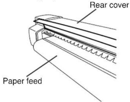
NOTE
- T urn OFF the printer power switch before cleaning.
- Do not blow off paper dust. If doing so, print quility gets bad influence.
■ Cleaning platen
When glue adheres to platen or ink drops on the platen, clean the platen according to the following procedures:
1 Open the rear cover and put a soft cloth on ink stained on the platen to infiltrate ink into the soft cloth.
Infiltrate ink into the soft cloth with care so as not to spread it.
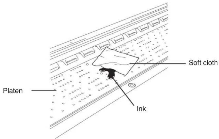
2 Wipe out the ink mark on the platen with a soft cloth moistened with alcohol.
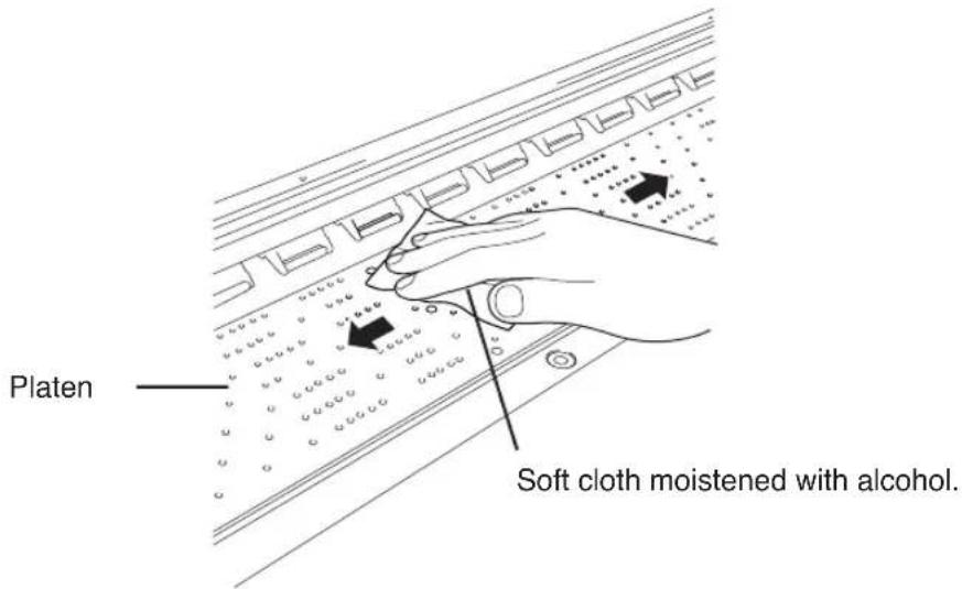
3 If ink gets into vacuum holes on the platen, wipe out ink clung to the holes with a commercially-available mini-cotton swab, then wipe out again with a mini-cotton swab moistened with alcohol.
Use a 3 mm mini-cotton swab.
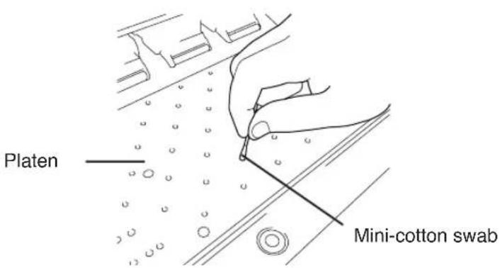
Section 3 Operation Panel Menu Operations
This section outlines the user menu structure and operations.
Contents of This Section
Basic Menu Operation
Menu Hierarchical Structure
Menu Tree
Basic Operations and Keys
Operation Procedures for Choice Input, Value Input, Execution and Character Input
Menu Operations
INK Menu
PAPER Menu
ENTRY Menu
F.ADJ Menu
SERVICE Menu
CLEANING Menu
FEED Menu
FUNC Menu
ADJUST Menu
SYSTEM Menu
RESET Menu
When the ONLINEs pressed in the online idle mode, the printer enters to the offline mode, a menu group appears on the LCD, and menu operations are enabled.
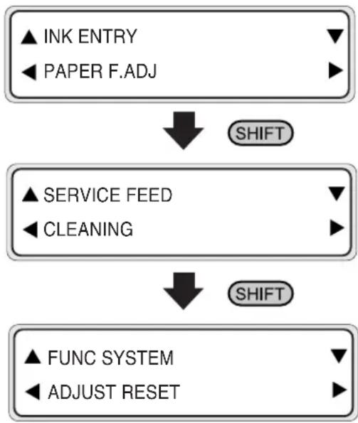
flowchart
graph TD
    A["▲ INK ENTRY\n◀ PAPER F.ADJ"] --> B["SHIFT"]
    C["▲ SERVICE FEED\n◀ CLEANING"] --> D["SHIFT"]
    E["▲ FUNC SYSTEM\n◀ ADJUST RESET"] --> D
Menu Hierarchical Structure
The menu has the following hierarchical structures: