MY4-AEC - Uncategorized YAMAHA - Free user manual and instructions
Find the device manual for free MY4-AEC YAMAHA in PDF.

User questions about MY4-AEC YAMAHA
0 question about this device. Answer the ones you know or ask your own.
Ask a new question about this device
Download the instructions for your Uncategorized in PDF format for free! Find your manual MY4-AEC - YAMAHA and take your electronic device back in hand. On this page are published all the documents necessary for the use of your device. MY4-AEC by YAMAHA.
USER MANUAL MY4-AEC YAMAHA
This product, when installed as indicated in the instructions contained in this manual, meets FCC requirements. Modifications not expressly approved by Yamaha may void your authority, granted by the FCC, to use the product.
-
IMPORTANT: When connecting this product to accessories and/or another product use only high quality shielded cables. Cable/s supplied with this product MUST be used. Follow all installation instructions. Failure to follow instructions could void your FCC authorization to use this product in the USA.
-
NOTE: This product has been tested and found to comply with the requirements listed in FCC Regulations, Part 15 for Class "B" digital devices. Compliance with these requirements provides a reasonable level of assurance that your use of this product in a residential environment will not result in harmful interference with other electronic devices. This equipment generates/uses radio frequencies and, if not installed and used according to the instructions found in the users manual, may cause interference harmful to the operation of other electronic devices. Compliance with FCC
regulations does not guarantee that interference will not occur in all installations. If this product is found to be the source of interference, which can be determined by turning the unit "OFF" and "ON", please try to eliminate the problem by using one of the following measures:
Relocate either this product or the device that is being affected by the interference.
Utilize power outlets that are on different branch (circuit breaker or fuse) circuits or install AC line filter/s.
In the case of radio or TV interference, relocate/reorient the antenna. If the antenna lead-in is 300 ohm ribbon lead, change the lead-in to co-axial type cable.
If these corrective measures do not produce satisfactory results, please contact the local retailer authorized to distribute this type of product. If you can not locate the appropriate retailer, please contact Yamaha Corporation of America, Electronic Service Division, 6600 Orangethorpe Ave, Buena Park, CA90620
The above statements apply ONLY to those products distributed by Yamaha Corporation of America or its subsidiaries.
* This applies only to products distributed by YAMAHA CORPORATION OF AMERICA. (class B)
CANADA
This Class B digital apparatus complies with Canadian ICES-003.
This device complies with Part 15 of the FCC Rules. Operation is subject to the following two conditions:
(1) this device may not cause harmful interference, and (2) this device must accept any interference received, including interference that may cause undesired operation.
* Please keep this manual in a safe place for future reference.

WARNING
Always follow the basic precautions listed below to avoid the possibility of serious injury or even death from electrical shock, short-circuiting, damages, fire or other hazards. These precautions include, but are not limited to, the following:
- Do not install the card in any Yamaha products not specified by Yamaha for use with the card to avoid possible electrical shock, fire, or equipment damage.
- Do not attempt to disassemble or modify the card. Do not apply excessive force to card connectors or other card components. Mishandling of the card may lead to shock, fire hazard, or equipment failure.
- Be sure to disconnect the power cable of the host device before installing the card and connecting/disconnecting the cables (in order to eliminate shock hazard, undesired noise, and avoid equipment damage).
- Turn off all peripheral devices connected to the host device before installation, and unplug all related cables (in order to eliminate shock hazard, undesired noise, and avoid equipment damage).

CAUTION
Always follow the basic precautions listed below to avoid the possibility of physical injury to you or others, or damage to the device or other property.
These precautions include, but are not limited to, the following:
- Be sure to properly ground the host device to prevent electrical shock and/or malfunction.
- Do not touch the metallic leads (pins) of the circuit board when handling the card. The pins are sharp and may cause hand cuts.
- Wear a pair of heavy gloves during installation to avoid scratching or cutting your hands on sharp edges.
- Avoid touching exposed connectors and metal parts to minimize the possibility of bad connections.
- Drain all static electricity from your clothing and body before handling the card. Static electricity can damage the card. Touch an exposed metal part of the host device or other grounded object beforehand.
- Do not drop the card or subject it to physical shock as this can result in breakage and/or malfunction.
- Do not drop screws or other small parts inside the card. If power is applied while screws or similar metal objects are loose inside the unit the card may malfunction or be damaged. If you cannot retrieve dropped objects yourself, refer the problem to qualified Yamaha service personnel.
Yamaha cannot be held responsible for damage caused by improper use or modifications to the device, or data that is lost or destroyed.
- The illustrations as shown in this manual are for instructional purposes only, and may be different from the ones on your equipment.
- The company names and product names in this manual are the trademarks or registered trademarks of their respective companies.
Information for Users on Collection and Disposal of Old Equipment
natural_image
Symbol of a trash bin crossed with a diagonal line, no text or numbers presentThis symbol on the products, packaging, and/or accompanying documents means that used electrical and electronic products should not be mixed with general household waste.
For proper treatment, recovery and recycling of old products, please take them to applicable collection points, in accordance with your national legislation and the Directives 2002/96/EC.
By disposing of these products correctly, you will help to save valuable resources and prevent any potential negative effects on human health and the environment which could otherwise arise from inappropriate waste handling.
For more information about collection and recycling of old products, please contact your local municipality, your waste disposal service or the point of sale where you purchased the items.
[For business users in the European Union]
If you wish to discard electrical and electronic equipment, please contact your dealer or supplier for further information.
[Information on Disposal in other Countries outside the European Union]
This symbol is only valid in the European Union. If you wish to discard these items, please contact your local authorities or dealer and ask for the correct method of disposal.
European models
Purchaser/User Information specified in EN55103-1 and EN55103-2.
Conforms to Environments: E1, E2, E3 and E4
Introduction
Thank you for choosing the Yamaha MY4-AEC. The MY4-AEC is an acoustic echo canceller card designed for use with the DME64N/24N Digital Mixing Engines that can effectively reduce troublesome acoustic echoes due to secondary pickup of speaker output and reflections from room surfaces in teleconferencing situations. It is also capable of reducing feedback as well as ambient noise from air conditioning and fans. This technology enables noise-free, high-intelligibility teleconferencing in just about any environment. Four AES/EBU input and output channels are provided, all with built-in sample rate conversion capability. The MY4-AEC can also connect to digital audio devices that do not allow word clock synchronization.
Installation
Refer to the DME64N/24N owner's manual for installation details. The screws on the left and right sides of the card also ground (earth) the device, so be sure to tighten them securely.
Supplied Items
- Owner's Manual (this document)
● 3-pin Euroblock plugs x 4 - Cable ties x 4
Principle of Operation
How Acoustic Echo and Noise are Reduced
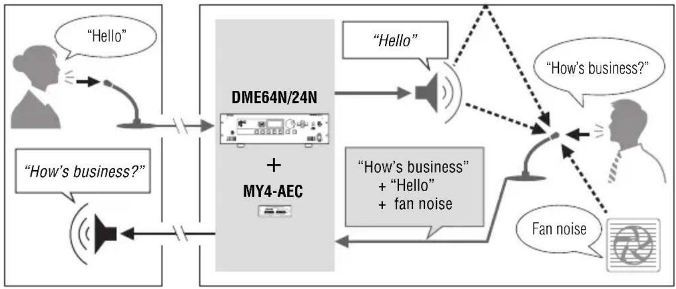
Acoustic echo occurs in a teleconferencing system when the sound from a speaker or reflections from surfaces of the room are picked up by a microphone and transmitted to the other party, resulting in a loss of intelligibility. Projectors and air conditioning systems also produce noise that can interfere with clear teleconferencing. The echo cancelling and noise reduction capabilities of the MY4-AEC help to achieve maximum clarity and intelligibility for smooth, effective communication.
Remote Local
flowchart
graph TD
    A["Hello"] --> B["DME64N/24N + MY4-AEC"]
    C["How's business?"] --> B
    B --> D["Hello"]
    B --> E[""How's business" + "Hello" + fan noise"]
    D --> F["How's business?"]
    E --> G["Fan noise"]
    F --> H["Fan noise"]
    G --> H
NOTE
In order to reduce acoustic echo originating from the remote location, an echo canceller must be installed and active at the remote location.
MY4-AEC Signal Flow
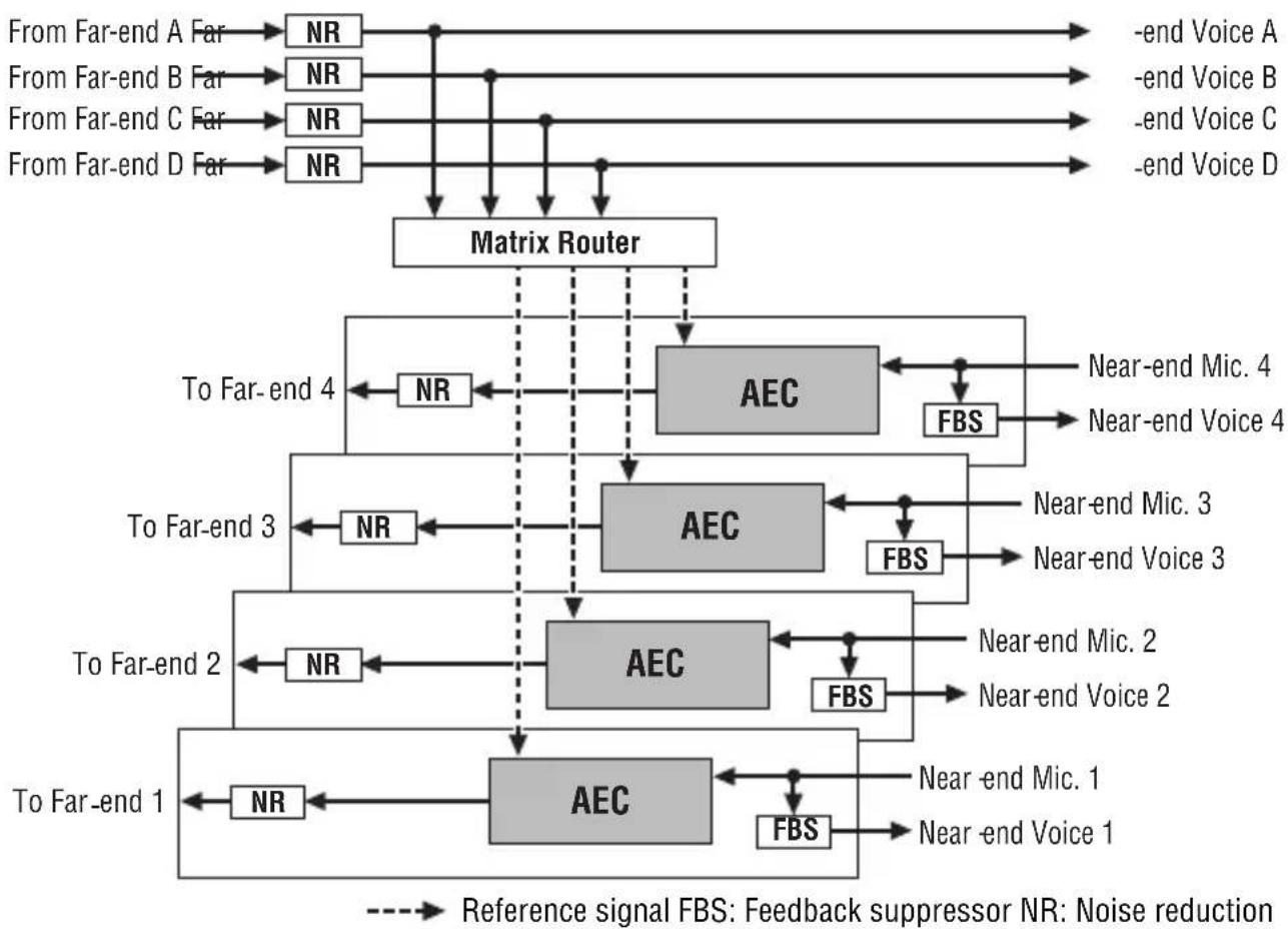
The local and remote locations in a teleconferencing system are referred to as the “near end” and “far end”, respectively. The MY4-AEC acoustic echo canceller (AEC) works by comparing the reference signal received from the far-end with the signal from the microphone in order to determine which components of the signal are echo, and then subtracts only the far-end echo component from microphone signal. The near-end sound is thus clearly transmitted to the far end without echo.
flowchart
graph TD
    A["From Far-end A Far"] --> B["NR"]
    C["From Far-end B Far"] --> D["NR"]
    E["From Far-end C Far"] --> F["NR"]
    G["From Far-end D Far"] --> H["NR"]
    B --> I["Matrix Router"]
    D --> I
    F --> I
    H --> I
    I --> J["To Far-end 4"]
    I --> K["AEC"]
    I --> L["FBS"]
    J --> M["NR"]
    K --> N["Near-end Mic. 4"]
    K --> O["Near-end Voice 4"]
    L --> P["NR"]
    M --> Q["To Far-end 3"]
    N --> R["NR"]
    O --> S["NR"]
    P --> T["AEC"]
    Q --> U["NR"]
    R --> V["AEC"]
    S --> W["FBS"]
    T --> X["To Far-end 2"]
    U --> Y["NR"]
    V --> Z["NR"]
    W --> AA["NR"]
    X --> AB["AEC"]
    Y --> AC["FBS"]
    Z --> AD["AEC"]
    AA --> AE["To Far-end 1"]
    AB --> AF["FBS"]
    AC --> AG["Near-end Mic. 1"]
    AD --> AH["NR"]
    AE --> AI["NR"]
    AF --> AJ["NR"]
    AG --> AK["FBS"]
    AH --> AL["NR"]
    AI --> AM["FBS"]
    AJ --> AN["Reference signal FBS: Feedback suppressor NR: Noise reduction"]
    AK --> AO["Noise reduction"]

The Connectors and Their Functions
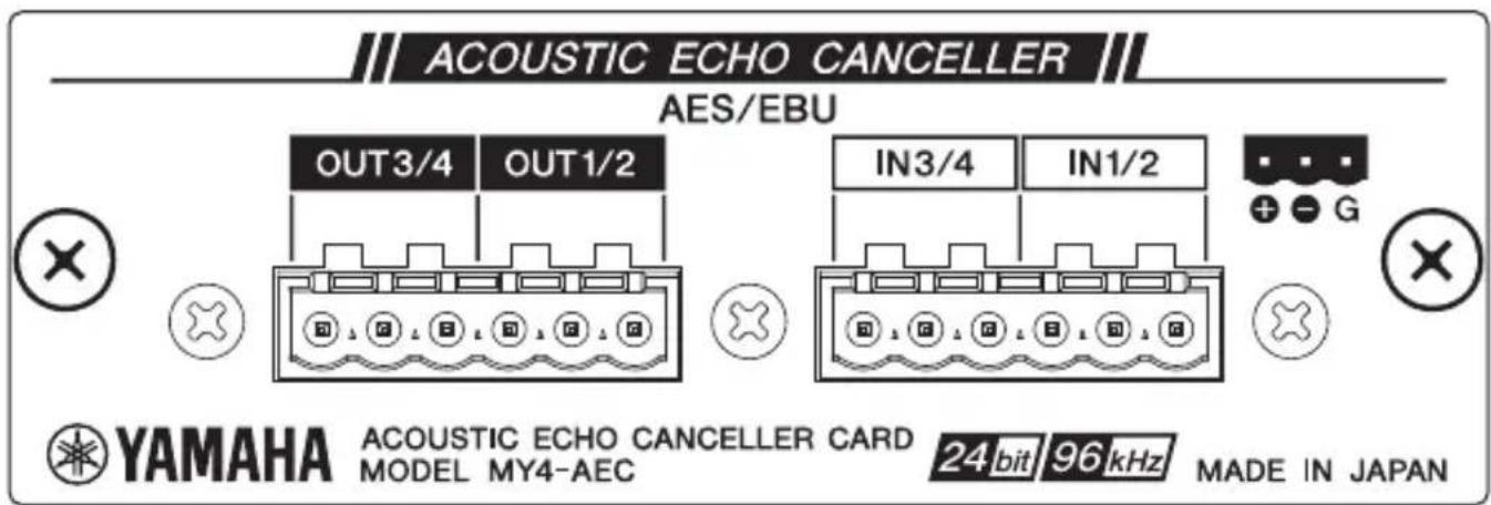
AES/EBU IN and OUT Connectors
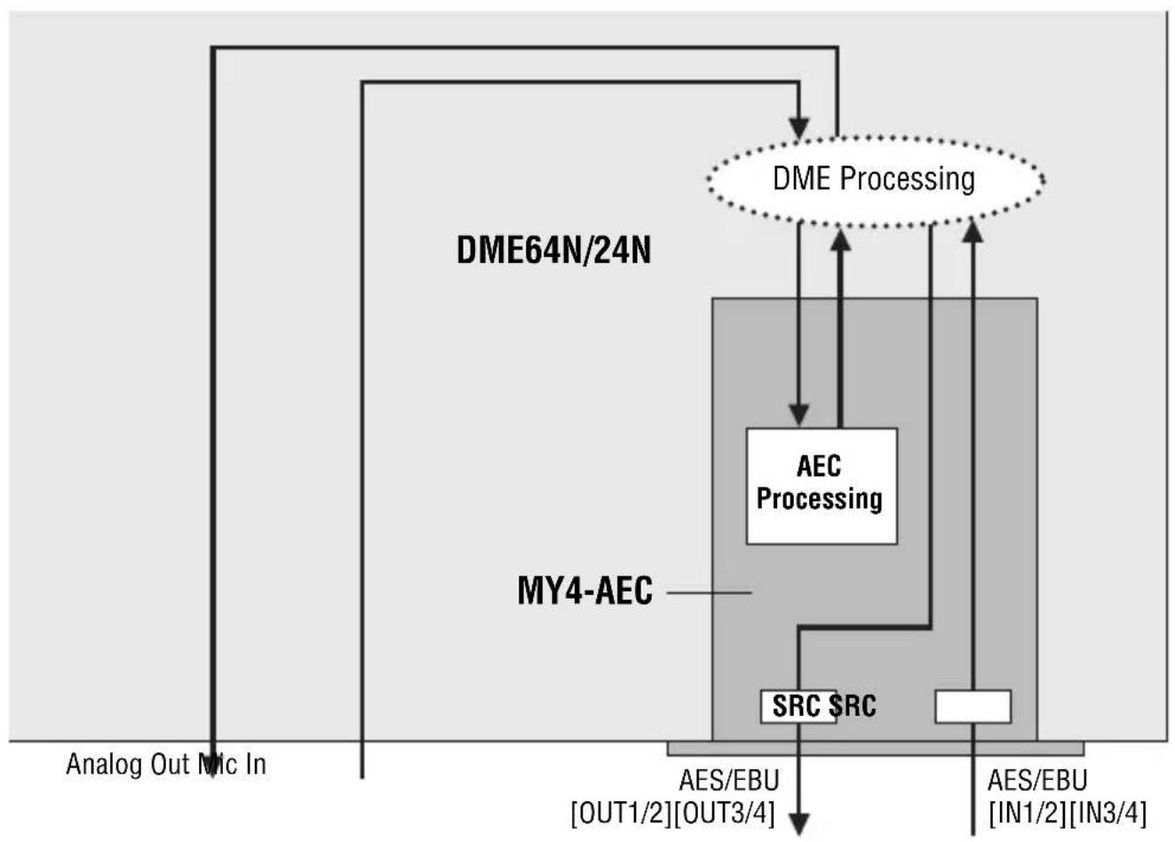
These connectors support four channels of AES/EBU format digital audio input and output to and from the host DME64N/24N unit, but those signals are not directly routed via the MY4-AEC processing section. Signals from the host's analog or digital inputs must be routed to the MY4-AEC card's AEC processing section via the host's processing section in order to apply echo cancellation, as shown in the illustration below. Operational details are provided in the DME Designer owner's manual. Built-in sample rate conversion is provided for all inputs and outputs (sample rate conversion settings are also made via the DME Designer software).
Use the supplied Euroblock plugs for connection (refer to "Euroblock Connection" on page 10).
NOTE
The channel 3 and channel 4 inputs and outputs ([IN3/4] and [OUT3/4] in the above illustration) cannot be used when the DME64N/24N word clock sampling rate is set to 88.2 kHz or 96 kHz.
flowchart
graph TD
    A["Analog Out Mic In"] --> B["DME64N/24N"]
    B --> C["MY4-AEC"]
    C --> D["AES/EBU [OUT1/2"][OUT3/4]]
    D --> E["AES/EBU [IN1/2"][IN3/4]]
    F["DME Processing"] --> G["AEC Processing"]
    G --> H["SRC SRC"]
    H --> I["AES/EBU"]
    I --> J["Analog Out Mic In"]
Euroblock Connection
Please be sure to use the supplied Euroblock plugs to connect the AES/EBU [IN] and [OUT] connectors.
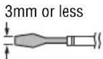
Cable preparation
- To prepare the cable for attachment to a Euroblock connector, strip the wire as shown in the illustration using stranded wire to make connections. With a Euroblock connection, stranded wires may be prone to breakage because of metal fatigue due to the weight of the cable or due to vibration. Bundle the cables and the
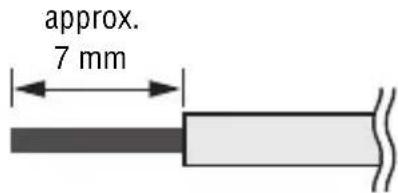
Euroblock tabs using the supplied cable ties (page 12). When rackmounting your equipment, use a lacing bar when possible to bundle and fasten the cables.
NOTE
Do not tin (plate with solder) the exposed end.
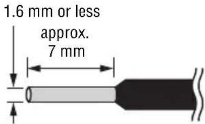
- If cables will be frequently connected and disconnected, as in the case of a portable installation, we recommend that you use ferrules with insulation sleeves. Use a ferrule whose conductor portion has an external diameter of 1.6 mm or less, and a length of approximately 7 mm (such as the Al0,5-6WH made by the Phoenix Contact corporation).
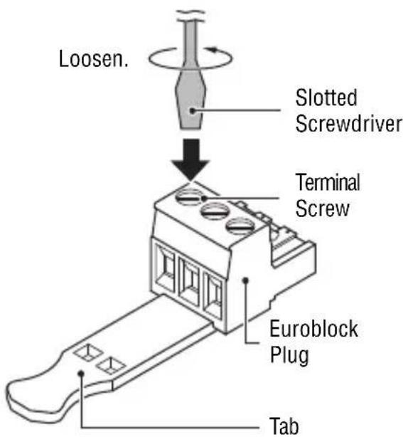
1 Loosen terminal screws.
NOTE
A slotted screwdriver with a blade width of about 3 millimeters is recommended.
2 Insert cables.
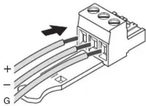
3 Securely tighten terminal screws.
Pull the cables (not too strongly) to confirm that they are securely connected.
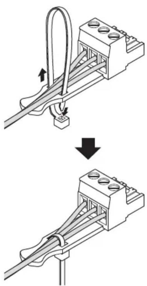
4 Bundle the cables and the Euroblock tab using the supplied cable tie.
NOTE
Trim any excess part of the cable tie as necessary.
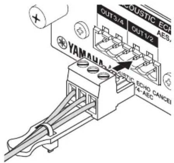
5 Insert the Euroblock plug into the AES/EBU [IN] or [OUT] connector of the MY4-AEC.
Example 1: Teleconferencing with a Remote Location
This is an example of a teleconferencing system set up to allow multiple participants to hold conferences with a remote location (“Office X”).
Preparation
The first step is to make the basic local (near end) connections and determine the optimum microphone and speaker locations as well as gain settings. The AEC system will have the best possible effect if these initial steps are carried out properly.
1 Prepare the following equipment.
- DME24N x 1
- MY4-AEC x 1
- Microphones x 4
- Speakers x 2
NOTE
Be sure to choose microphones and speakers that have good frequency response characteristics in order to ensure optimum AEC operation.
2 Connect the microphones and speakers to the analog [IN] and [OUT] connectors on the DME24N rear panel as shown in the diagram.
Meeting Room (Near End)
![YAMAHA MY4-AEC - Connect the microphones and speakers to the analog [IN] and [OUT] connectors on the DME24N rear panel as shown in the diagram. - 1](/content/2026/06/1167707/images/e8d28fd8a7c03a0508e4e60ed25400e1ddac1f033675299a2ceb054af1bab758.jpg)
flowchart
graph TD
    A["OUT (Analog)"] --> B["DME24N + MY4-AEC"]
    B --> C["Speaker 1"]
    B --> D["Speaker 2"]
    B --> E["IN (Analog)"]
    C --> F["Microphone 1"]
    C --> G["Microphone 2"]
    C --> H["Microphone 3"]
    C --> I["Microphone 4"]
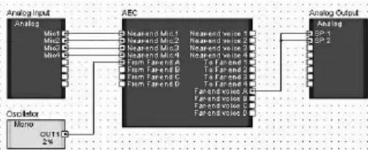
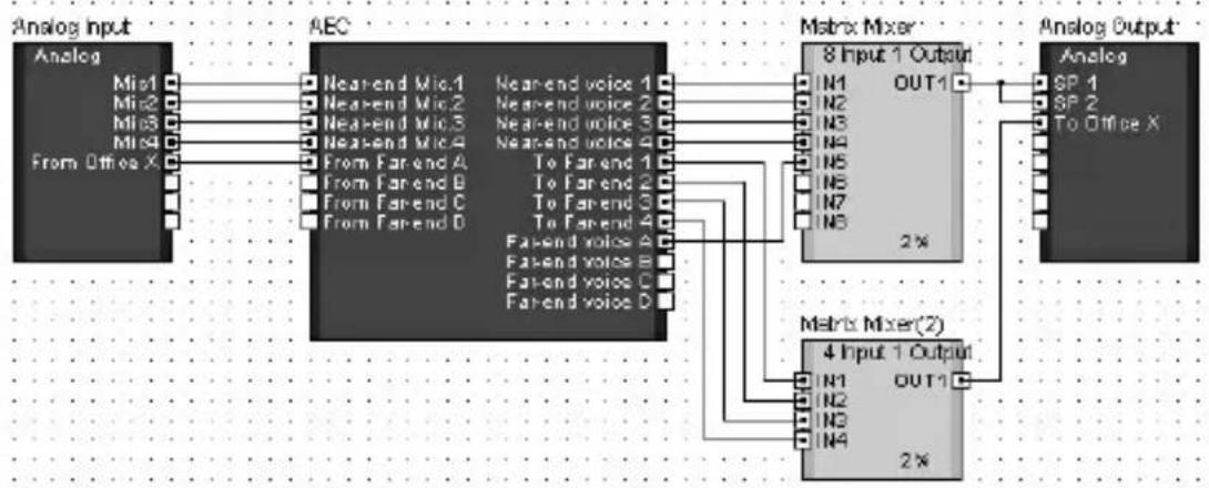
3 Make the required virtual connections in the DME Designer configuration window.
- Connect the signals from microphone inputs 1 – 4 to the “Near-end Mic. 1” – “Near-end Mic. 4” inputs on the AEC component.
- Place an oscillator that will be used for AEC adjustment in the configuration window and connect it to the AEC component "From Far-end A" input.
- The "Far-end voice A" output is connected to the conference room speakers (SP 1 and SP 2) in parallel.
flowchart
graph LR
    A["Analog Input"] --> B["Micro"]
    A --> C["Micro"]
    A --> D["Micro"]
    A --> E["Micro"]
    F["C Oscillator"] --> G["Mono OUT1 2%"]
    B --> H["AEC"]
    C --> H
    D --> H
    E --> H
    H --> I["Analog Output"]
    subgraph AEC
        J["Near-end Mic1"] & J["Near-end Mic2"] & J["Near-end Mic3"] & J["Near-end Mic4"] & J["Farm Farend A"] & J["Farm Farend B"] & J["Farm Farend C"] & J["Farm Farend D"]
        K["Near-end voice 1"] & K["Near-end voice 2"] & K["Near-end voice 3"] & K["Near-end voice 4"] & K["To Farend 1"] & K["To Farend 2"] & K["To Farend 3"] & K["To Farend 4"]
        L["Farend voice A"] & M["Farend voice B"] & N["Farend voice C"] & O["Farend voice D"]
    end
    subgraph Analog Output
        P["Analog SP-1"] & Q["Analog SP-2"]
    end
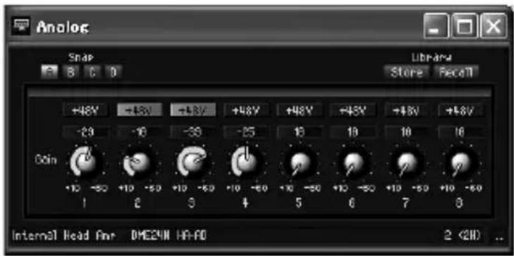
4 Speak into the microphones as you would during an actual conference and adjust the input gain of each channel.
Adjust the DME24N HA Gain while watching the "Mic. In" meters in the AEC component editor so that the yellow segment lights only occasionally.
NOTE
AEC may not function properly if the gain is set too high.
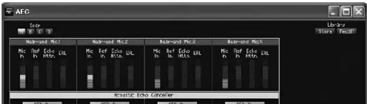
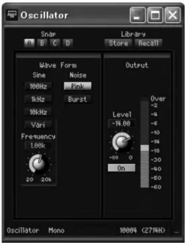
5 Open the Oscillator component editor, set the Wave Form type to "Pink," and engage the Output section "On" button.
Go back to the AEC component editor and, while watching the "Ref. In" meter, adjust the oscillator output level so that the yellow segment lights only occasionally.
6 Check that the ERL (Echo Return Loss) meter in the AEC component is moving.
If this meter is moving over a wide range it means that a large portion of the pink noise being output from the speaker is being picked up by the corresponding microphone, and therefore a large amount of echo will be transmitted to the remote location. Carefully adjust the positions and pickup directions of the four microphones in relation to the speakers in order to reduce this echo level as much as possible. The more you can reduce the echo at this stage, the more effective the AEC will be.
NOTE
- If the local meeting room is very reflective or reverberant, it may be difficult to reduce the echo level sufficiently by simply repositioning the microphones and speakers. In such cases it may be necessary to apply acoustic panels to the walls or use other means to reduce room reflections.
- If only the green segment of the ERL meter lights, setting the “Effect” parameter to 1 or 2 should be optimum, but if the yellow segment of the ERL meter lights an “Effect” setting of 3 or 4 will be required to produce the best results. Since the actual effectiveness of the processing will depend on the rooms in which it is used it is important make adjustments while actually connected to and conferring with the remote location.
- If the input signal becomes distorted for any reason before it reaches the Near-end Mic. 1 – 4 inputs of the AEC component, echo cancelling will not function properly.
7 Enter the microphone-to-speaker distance in meters into the Acoustic Echo Canceller section "Distance" field.
If multiple speakers are used, enter the distance between the microphone and nearest speaker for each channel.
If the distance is less than 2 meters, use the default value of "2". For greater distances enter the appropriate value.
Remote Connection and Settings
1 Connect the microphones, speakers, and teleconferencing system to the analog [IN] and [OUT] connectors on the rear panel of the DME24N as shown in the diagram.
Four microphones can be connected at the near-end location, allowing multiple conference participants.
![YAMAHA MY4-AEC - Connect the microphones, speakers, and teleconferencing system to the analog [IN] and [OUT] connectors on the rear panel of the DME24N as shown in the diagram. - 1](/content/2026/06/1167707/images/bcc6b25863aa8e58e14dd881034c2c18d99131148974617b7916ab70980d7bef.jpg)
flowchart
graph TD
    A["Office X (Remote - Far End)"] --> B["Network"]
    B --> C["DME24N + MY4-AEC"]
    C --> D["IN/OUT (Analog)"]
    C --> E["IN (Analog)"]
    C --> F["OUT (Analog)"]
    C --> G["Speaker 1"]
    C --> H["Speaker 2"]
    C --> I["Microphone 1"]
    C --> J["Microphone 2"]
    C --> K["Microphone 3"]
    C --> L["Microphone 4"]
    C --> M["Teleconferencing system"]
2 Make the required virtual connections in the DME Designer configuration window.
- Connect the signal from the four local microphones (Mic1 – Mic4) and the audio signal from the remote location (From Office X) to the appropriate inputs of the AEC component.
- Mix the “Near-end Voice 1” – “Near-end Voice 4” outputs and the “Far-end Voice A” outputs from the AEC component and connect the mixed output in parallel to the meeting room speakers (SP 1 and SP 2).
- Mix the "To Far-end 1" – "To Far-end 4" outputs from the AEC component and connect the mixed output to "To Office X" for transmission to the remote location.
HINT
When multiple speakers are being used in the local meeting room, be sure to connect the mixed signal to them in parallel. AEC may not function properly if the output balance between the speakers changes.
flowchart
graph LR
    A["Analog Input"] --> B["AEC"]
    B --> C["Matrix Mixer"]
    C --> D["Analog Output"]

    subgraph Analog Input
        A1["Analog"] --> A2["AEC"]
        A2 --> A3["Matrix Mixer"]
        A3 --> C
    end

    subgraph AEC
        A1 --> A2
        A2 --> A3
    end

    subgraph Matrix Mixer
        C1["8 Input 1 Output"] --> C2["Analog"]
        C2 --> C3["Analog Output"]

    end

    subgraph Analog Output
        D1["Analog"] --> D2["Analog Output"]

    end

    A1 --> A2
    A2 --> A3
    A3 --> C1
    C1 --> D1
    D1 --> E1["SP 1"]
    D1 --> E2["SP 2"]
    D1 --> E3["To Office X"]

    subgraph AEC
        A1 --> A2
        A2 --> A3
        A3 --> C1
        C1 --> D1
        D1 --> E1
        E1 --> F1["SP 1"]
    end

    subgraph Matrix Mixer
        C1 --> C2
        C2 --> C3
        C3 --> D1
        D1 --> E1
        E1 --> F1["SP 2"]
    end

    subgraph Analog Output
        D1 --> D2
        D2 --> D3["Analog Output"]

    end

    A1 --> A2
    A2 --> A3
    A3 --> C1
    C1 --> D1
    D1 --> E1
    E1 --> F1

    subgraph Analog Output
        D1 --> D2
        D2 --> D3
        D3 --> E1
        E1 --> F1

    end

    A1 --> A2
    A2 --> A3
    A3 --> C1
    C1 --> D1
    D1 --> E1

    subgraph Matrix Mixer
        C1 --> C2
        C2 --> C3
        C3 --> D1
        D1 --> E1

    end

    subgraph Analog Output
        D1 --> D2
        D2 --> D3
        D3 --> E1

    end

    A1 --> A2
    A2 --> A3
    A3 --> C1
    C1 --> D1
    D1 --> E1

    subgraph Matrix Mixer(2)
        C1 --> C2
        C2 --> C3
        C3 --> D1
        D1 --> E1

    end

    subgraph Analog Output
        D1 --> D2
        D2 --> D3
        D3 --> E1

    end

    A1 --> A2
    A2 --> A3
    A3 --> C1
    C1 --> D1
    D1 --> E1

    sub- {{Matrix Mixer(2)}}
    end

    subgraph Analog Output
        C1 --> C2
        C2 --> C3
        C3 --> D1
        E1 --> E1

    end

    subgraph Matrix Mixer(2)
        C1 --> C2
        C2 --> C3
        C3 --> D1
        E1 --> E1

    end

    subgraph Analog Output
        D1 --> D2
        D2 --> D3
        D3 --> E1

    end

    subgraph Matrix Mixer(2)
        C1 --> C2
        C2 --> C3
        C3 --> D1
        E1 --> E1

    end

    subgraph Analog Output
        D1 --> D2
        D2 --> D3
        D3 --> E1

    end

    subgraph Matrix Mixer(2)
        C1 --> C2
        C2 --> C3
    end
3 Adjust the DME Designer AEC component editor parameters so that acoustic echo is effectively cancelled from the audio signal sent to Office X.
Begin by checking that the connection with Office X is working properly and that conversation is possible. If echo can be heard with the default AEC section Effect setting of “1”, try increasing the setting in small increments. Echo cancellation efficiency will increase as the setting is increased, but sound quality will decrease at the same time so it is necessary to find the best setting for conditions in the local meeting room while actually listening to the audio signal.
Other parameters can usually be left at their default settings. Refer to the DME Designer owner's manual for details on the individual AEC component parameters.
Example 2: Teleconferencing with Two Remote Locations from Two Meeting Rooms
Using one MY4-AEC card, multiple participants in two meeting rooms can teleconference with two separate remote locations (“Office X” and “Office Y”).
Preparation
Referring to Example 1, use an oscillator component to determine the ideal microphone and speaker positions for each meeting room.
The following equipment is used.
- DME24N x 1
- MY4-AEC x 1
- Microphones x 4
- Speakers x 4
Remote Connection and Settings
1 Connect the microphones, speakers, and teleconferencing system to the analog [IN] and [OUT] connectors on the rear panel of the DME24N as shown in the diagram.
A total of four microphones can be connected for the medium and small near-end meeting rooms, allowing multiple participants to confer simultaneously in both rooms.
![YAMAHA MY4-AEC - Connect the microphones, speakers, and teleconferencing system to the analog [IN] and [OUT] connectors on the rear panel of the DME24N as shown in the diagram. - 1](/content/2026/06/1167707/images/b389ad56d45a7ef62098661010e54c93f5f3ff301294fdbac19828d5b33c071f.jpg)
flowchart
graph TD
    subgraph_Small_Meeting_Room["Small Meeting Room (Near End)"]
        A["Office X (Remote - Far End)"] --> B["Network"]
        B --> C["Teleconferencing system"]
        C --> D["DME24N + MY4-AEC"]
        D --> E["OUT (Analog)"]
        D --> F["IN (Analog)"]
        G["Office Y (Remote - Far End)"] --> H["Network"]
        H --> I["Teleconferencing system"]
        I --> J["DME24N + MY4-AEC"]
        J --> K["OUT (Analog)"]
        J --> L["IN (Analog)"]
    end

    subgraph_Medium_Meeting_Room["Medium Meeting Room (Near End)"]
        M["Office X (Remote - Far End)"] --> N["Network"]
        N --> O["Teleconferencing system"]
        O --> P["DME24N + MY4-AEC"]
        P --> Q["OUT (Analog)"]
        P --> R["IN (Analog)"]
        S["Office Y (Remote - Far End)"] --> T["Network"]
        T --> U["Teleconferencing system"]
        U --> V["DME24N + MY4-AEC"]
        V --> W["OUT (Analog)"]
        V --> X["IN (Analog)"]
    end

    style Small_Meeting_Room fill:#f9f9f9,stroke:#333
    style Medium_Meeting_Room fill:#f9f9f9,stroke:#333
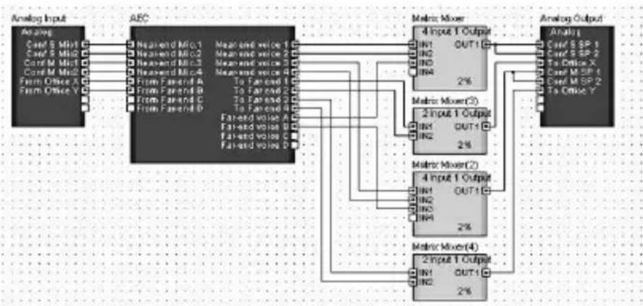
2 Make the required virtual connections in the DME Designer configuration window.
- Connect the signal from the microphones in the small and medium local meeting rooms (Conf S Mic1/2 and Conf M – Mic1/2) and the audio signal from the remote locations (From Office X and From Office Y) to the appropriate inputs of the AEC component.
- Mix the “Near-end Voice 1” and “Near-end Voice 2” outputs and the “Far-end Voice A” outputs from the AEC component and connect the mixed output in parallel to the small meeting room speakers (Conf S SP 1 and SP 2).
- Mix the "Near-end Voice 3" and "Near-end Voice 4" outputs and the "Far-end Voice B" outputs from the AEC component and connect the mixed output in parallel to the medium meeting room speakers (Conf M SP 1 and SP 2).
- Mix the "To Far-end 1" and "To Far-end 2" outputs from the AEC component and connect the mixed output to "To Office X" for transmission to remote Office X.
- Mix the "To Far-end 3" and "To Far-end 4" outputs from the AEC component and connect the mixed output to "To Office Y" for transmission to remote Office Y.
HINT
When multiple speakers are being used in the same meeting room, be sure to connect the mixed signal to them in parallel. AEC may not function properly if the output balance between the speakers changes.
flowchart
graph TD
    A["Analog Input"] --> B["AEC"]
    B --> C["Matrix Mixer"]
    C --> D["Analog Output"]

    subgraph AEC
        E1["Nearend Mio.1"] --> F1["4 Input 1 Output"]
        E2["Nearend Mio.2"] --> F2["4 Input 1 Output"]
        E3["Nearend Mio.3"] --> F3["4 Input 1 Output"]
        E4["Nearend Mio.4"] --> F4["4 Input 1 Output"]
        E5["From Far friend A"] --> F5["4 Input 1 Output"]
        E6["From Far friend B"] --> F6["4 Input 1 Output"]
        E7["From Far friend C"] --> F7["4 Input 1 Output"]
        E8["From Far friend D"] --> F8["4 Input 1 Output"]
    end

    subgraph AEC
        G1["Mean and voice 1"] --> H1["IN1 OUT1"]
        G2["Mean and voice 2"] --> H2["IN2 OUT1"]
        G3["Mean and voice 3"] --> H3["IN3 OUT1"]
        G4["Mean and voice 4"] --> H4["IN4 OUT1"]
        G5["To Far friend 1"] --> H5["IN5 OUT1"]
        G6["To Far friend 2"] --> H6["IN6 OUT1"]
        G7["To Far friend 3"] --> H7["IN7 OUT1"]
        G8["To Far friend 4"] --> H8["IN8 OUT1"]
        G9["Far friend voice 1"] --> H9["IN9 OUT1"]
        G10["Far friend voice 2"] --> H10["IN10 OUT1"]
        G11["Far friend voice 3"] --> H11["IN11 OUT1"]
        G12["Far friend voice 4"] --> H12["IN12 OUT1"]
    end

    subgraph Matrix Mixer
        I1["Matrix Mixer(3)"] --> J1["2%"]
        I2["Matrix Mixer(2)"] --> J2["2%"]
        I3["Matrix Mixer(4)"] --> J3["2%"]
    end

    subgraph Analog Output
        K1["Analog Input"] --> L1["Analyst"]
        K2["Analog Output"] --> M1["Analyst"]
    end
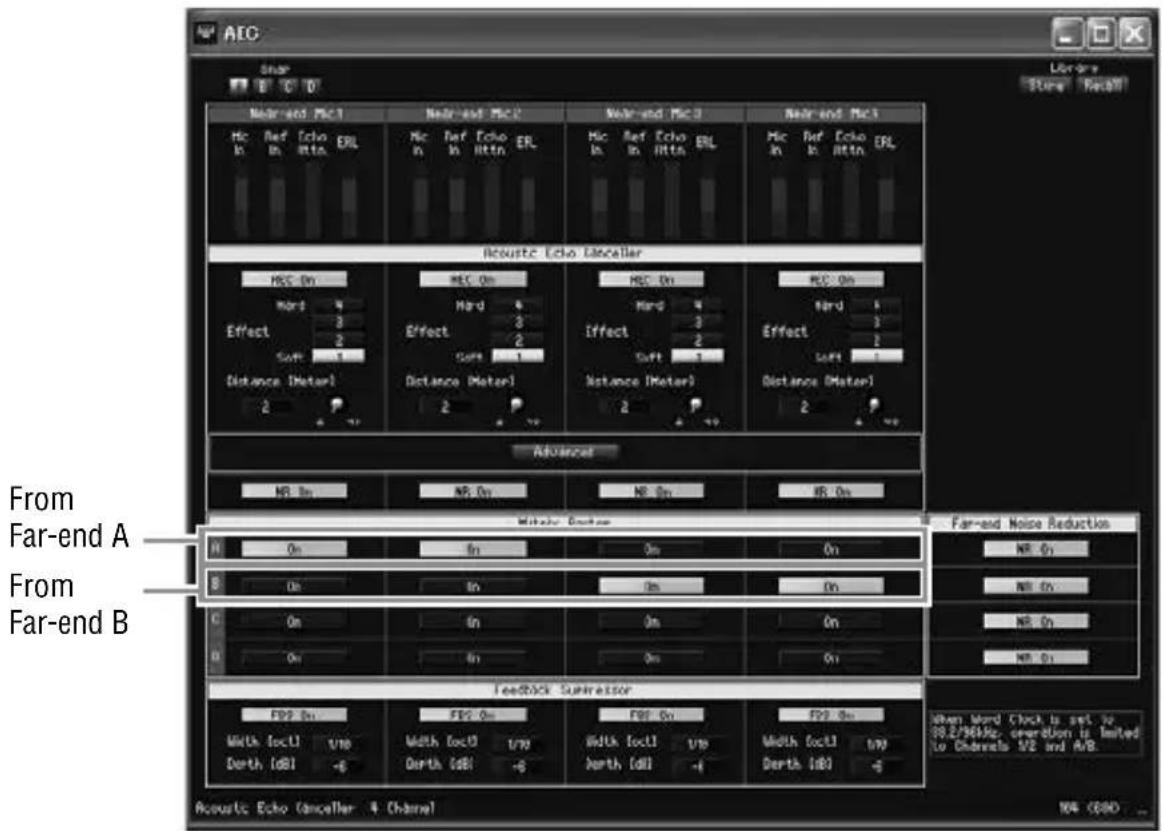
3 In the Matrix Router section of the AEC component editor, select one or more of the “From Far-end A – D signals” to be used as the reference for each AEC channel 1 – 4.
The "On" buttons in the Matrix Router section can be used to select microphones and locations for each meeting room.
For this example the Matrix Router is set as shown below. With these settings it is possible to simultaneously hold independent conferences between the small meeting room and Office X (Far-end A) using AEC channels 1 and 2, and between the medium meeting room and Office Y (Far-end B) using AEC channels 3 and 4.
Specifications
- GENERAL SPECIFICATIONS
| Sampling Frequency 44.1kHz-10% to 48kHz+6%,88.2kHz-10% to 96kHz+6% | z+6%, | |
| Power requirements 5V:395mA | ||
| 3.3V:295mA | ||
| Temperature Range Operating 0 to +40°C | ||
| Storage -20 to +60°C | ||
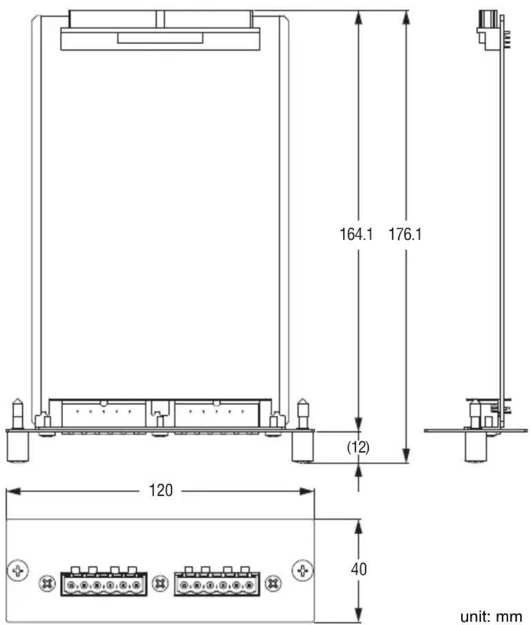
| Weight 160g | ||
- DIGITAL INPUT/OUTPUT CHARACTERISTICS
| Terminal | Format | Audio Data Length | Level | Connector |
| IN 1/2, 3/4 | AES/EBU | 24bit | RS422 | Euroblock |
| OUT 1/2, 3/4 | AES/EBU(Professional use) | 24bit | RS422 | Euroblock |
Dimensions
* The contents of this manual apply to the latest specifications as of the publishing date. To obtain the latest manual, access the Yamaha website then download the manual file.
* Der Inhalt dieser Bedienungsanleitung gilt für die neuesten technischen Daten zum Zeitpunkt der Veröffentlichung. Um die neueste Version der Anleitung zu erhalten, rufen Sie die Website von Yamaha auf und laden Sie dann die Datei mit der Bedienungsanleitung herunter.
* Le contenu de ce mode d'emploi s'applique aux dernières caractéristiques techniques connues à la date de publication du manuel. Pour obtenir la version la plus récente du manuel, accédez au site Web de Yamaha puis téléchargez le fichier du manuel concerné.
* El contenido de este manual se aplica a las últimas especificaciones según la fecha de publicación. Para obtener el último manual, acceda al sitio web de Yamaha y descargue el archivo del manual.
* Il contenuto del presente manuale si applica alle ultime specifiche tecniche a partire dalla data di pubblicazione. Per ottenere la versione più recente del manuale, accedere al sito Web Yamaha e scaricare il file corrispondente.
* В содержании данного руководства приведены последние на момент публикации технические характеристики. Для получения последней версии руководства посетите веб-сайт корпорации Yamaha и загрузите файл с руководством.
* 本使用说明书的内容为出版时最新的技术规格。请至Yamaha网站下载最新版本的使用说明书。
* この取扱説明書では、発行時点の最新仕様で説明をしております。最新版の取扱説明書につきましては、ヤマハウエブサイトからダウンロードしてお読みいただけますようお願いいたします。
Memo
Memo
Important Notice: Guarantee Information for customers in European Economic Area (EEA) and Switzerland
| Important Notice: Guarantee Information for customers in EEA* and SwitzerlandFor detailed guarantee information about this Yamaha product, and Pan-EEA* and Switzerland warranty service, please either visit the website address below (Printable file is available at our website) or contact the Yamaha representative office for your country. * EEA: European Economic Area | English |
| Wichtiger Hinweis: Garantie-Information für Kunden in der EWR* und der SchweizFür nähere Garantie-Information über dieses Produkt von Yamaha, sowie über den Pan-EWR*- und Schweizer Garantieservice, besuchen Sie bitte entweder die folgend angegebene Internetadresse (eine druckfähige Version befindet sich auch auf unserer Webseite), oder wenden Sie sich an den für Ihr Land zuständigen Yamaha-Vertrieb. *EWR: Europäischer Wirtschaftsraum | Deutsch |
| Remarque importante: informations de garantie pour les clients de l'EEE et la SuissePour des informations plus détaillées sur la garantie de ce produit Yamaha et sur le service de garantie applicable dans l'ensemble de l'EEE ainsi qu'en Suisse, consultez notre site Web à l'adresse ci-dessous (le fichier imprimable est disponible sur notre site Web) ou contactez directement Yamaha dans votre pays de résidence. * EEE : Espace Economique Européen | Français |
| Belangrijke mededeling: Garantie-informatie voor klanten in de EER* en ZwitserlandVoor gedetailleerde garantie-informatie over dit Yamaha-product en de garantieservice in heel de EER* en Zwitserland, gaat u naar de onderstaande website (u vind een afdrukbaar bestand op onze website) of neemt u contact op met de vertegenwoordiging van Yamaha in uw land.* EER: Europese Economische Ruimte | Nederlands |
| Aviso importante: información sobre la garantía para los clientes del EEE* y SuizaPara una información detallada sobre este producto Yamaha y sobre el soporte de garantía en la zona EEE* y Suiza, visite la dirección web que se incluye más abajo (la version del archivo para imprimir esta disponible en nuestro sitio web) o póngase en contacto con el representante de Yamaha en su país. * EEE: Espacio Económico Europeo | Español |
| Avviso importante: informazioni sulla garanzia per i clienti residenti nell'EEA* e in SvizzeraPer informazioni dettagliate sulla garanzia relativa a questo prodotto Yamaha e l'assistenza in garanzia nei paesi EEA* e in Svizzera, potete consultare il sito Web all'indirizzo riportato di seguito (è disponibile il file in formato stampabile) oppure contattare l'ufficio di rappresentanza locale della Yamaha. * EEA: Area Economica Europea | Italiano |
| Aviso importante: informações sobre as garantias para clientes da AEE* e da SuíçaPara obter uma informação pormenorizada sobre este produto da Yamaha e sobre o serviço de garantia na AEE* e na Suíça, visite o site a seguir (o arquivo para impressão está disponível no nosso site) ou entre em contato com o escritório de representação da Yamaha no seu país. * AEE: Área Econômica Européia | Português |
| Σημαντική σημείωση: Πληροφορίες εγγύησης για τους πελάτες στον ΕΟΧ* και ΕλβετίαΓια λεπτομερείς πληροφορίες εγγύησης σχετικά με το παρόν προϊόν της Yamaha και την κάλυψη εγγύησης σε όλες τις χώρες του ΕΟΧ και την Ελβετία, επισκεφτείτε την παρακάτω ιστοσελίδα (Εκτυπώσιμη μορφή είναι διαθέσιμη στην κτοσελίδα μας) ή απευθυνθείτε στην αντιπροσωπεία της Yamaha στη χώρα σας. * ΕΟΧ: Ευρωπαϊκός Οικονομικός Χώρος | Ελληνικά |
| Viktigt: Garantiinformation för kunder i EES-området* och SchweizFör detaljerad information om donna Yamahaprodukt samt garantiservice i hela EES-området* och Schweiz kan du antingen besöka nedanstående webbaddress (en utskriftsvänlig fil finns på webbplatsen) eller kontakta Yamahas officiella representant i ditt land. * EES: Europeiska Ekonomiska Samarbetsområdet | Svenska |
| Viktig merknad: Garantiinformasjon for kunder i E∅S* og SveitsDetaljert garantiinformasjon om dette Yamaha-produktet og garantiservice for hele E∅S-området* og Sveits kan fås enten ved å besøke nettadressen nedenfor (utskriftsversjon finnes på våre nettsider) eller kontakte kontakte Yamaha-kontoret i landet der du bor. *E∅S: Det europeiske økonomiske samarbeidsområdet | Norsk |
| Vigtig oplysning: Garantioplysninger til kunder i E∅O* og SchweizDe kan finde detaljerede garantioplysninger om dette Yamaha-produkt og den fælles garantiserviceordning for E∅O* (og Schweiz) ved at besøge det websted, der er angivet nedenfor (der findes en fil, som kan udskrives, på vores websted), eller ved at kontakte Yamahas nationale repräsentationskontor i det land, hvor De bor. * E∅O: Det Europæiske ∅konomiske Område | Dansk |
| Tärkeä ilmoitus: Takuutiedot Euroopan talousalueen (ETA)* ja Sveitsin asiakkailleTämän Yamaha-tuotteen sekä ETA-alueen ja Sveitsin takuuta koskevat yksityiskohtaiset tiedot saatte alla olevasta nettiosoitteesta. (Tulostettava tiedosto saatavissa sivustollamme.) Voitte myös ottaa ynteyttä paikalliseen Yamaha-edustajaan.*ETA: Euroopan talousalue | Suomi |
| Ważne: Warunki gwarancyjne obowiązujące w EOG* i SzwajcariiAby dowiedzieć się więcej na temat warunków gwarancyjnych tego produktu firmy Yamaha i serwisu gwarancyjnego w całym EOG* i Szwajcarii, należy odwiedzić wskazaną poniżej stronę internetową (Plik gotowy do wydruku znajduje się na naszej stronie internetowej) lub skontaktować się z przedstawicielstwem firmy Yamaha w swoim kraju. * EOG — Europejski Obszar Gospodarczy | Polski |
| Dûležité oznámení: Záruční informace pro zákazniky v EHS* a ve ŠvýcarskuPodrobné záruční informace o tomto produktu Yamaha a záručním servisu v celém EHS* a ve Švýcarsku naleznete na niže uvedené webové adrese (soubor k tisku je dostupný na našich webových stránkách) nebo se műžete obrátit na zastoupení firmy Yamaha ve své zemi. * EHS: Evropský hospodářský prostor | Česky |
| Fontos figyelmeztetés: Garancia-információk az EGT* területén és Svájcban élő vásárlók számáraA jelen Yamaha termékre vonatkozó részletes garancia-információk, valamint az EGT*-re és Svájcra kiterjedő garanciális szolgáltatás tekintetében keresse fel webhelyünket az alábbi címen (a webhelyen nyomtatható fájlt is talál), vagy pedig lépjen kapcsolatba az országában működő Yamaha képviseleti irodával. * EGT: Európai Gazdasági Térség | Magyar |
| Oluline márkus: Garantiiteave Euroopa Majanduspiirkonna (EMP)* ja Šveitsi klientideleTápsema teabe saamiseks solle Yamaha toote garantii ning kogu Euroopa Majanduspiirkonna ja Šveitsi garantiteeninduse kohta, külastage palun veebisaiti alljärgneval aadressil (mele saidil on saadaval prinditav fail) või põörduge Teie regiooni Yamaha esinduse poole. * EMP: Euroopa Majanduspiirkond | Eesti keel |
| Svarīgs paziņojums: garantijas informacija klientiem EEZ* un ŠveicēLai sarņemlu detalizėtu garantijas informaciju par šo Yamaha produktu, kā arī garantijas apkalpošanu EEZ* un Šveicē, lūdzu, apmeklējet zemāk norādīlo tīmekja vietnes adresi (tīmekja vietně ir pieejams drukājams fails) vai sazinieties ar jūsu valsti apkalpojošo Yamaha pārstāvniecību. * EEZ: Europas Ekonomikas zona | Latviešu |
| Dėmesio: informacija dėl garantijos pirkėjams EEE* ir ŠveicarijojeJei reikia išsamios informacijos apie šj „Yamaha* produktą ir jo techninę priežiūrą visoje EEE* ir Šveicarijoje, apsilankykite mūsų svetainėje loliau nurodyłu adresu (svetainėje yra spausdītinas failas) arba kreipkitės į „Yamaha* atstovybę savo šaliai.*EEE – Europos ekonominė erdvė | Lietuvių kalba |
| Dôležité upozornenie: Informácie o záruke pre zákazníkov v EHP* a ŠvajčiarskuPodrobné informácie o záruke týkajúce sa tohlo produktu od spoločnosti Yamaha a garančnom servise v EHP* a Švajčiarsku najdete na webovej stránke uvedenej nižšie (na našej webovej stránke je k dispozícii súbor na tlač) alebo sa obráťte na zástupcu spoločnosti Yamaha vo svojej krajine.* EHP: Európsky hospodářsky priestor | Slovenčina |
| Pomembno obvestilo: Informacije o garanciji za kupce v EGP* in ŠviciZa podrobnejše informacije o tem Yamahinem izdelku ter garancijskem servisu v celotnem EGP in Švici, obiščite spletno mestvo, ki je navedeno spodaj (nalistjiva datoteka je na voljo na našem spletnem mestvo), ali se obrnile na Yamahinega predstavnika v svoji državi. * EGP: Evropski gospodarski prostor | Slovenščina |
| Важно съобщение: Информация за гаранцията за клиенти в ЕИП* и ШвейцарияЗа подробна информация за гаранцията за този продукт на Yamaha и garанционното обслужване в паневропейската зона на ЕИП* и Швейцария или посетете посочения по-долу уеб сайт (на нашия уеб сайт има файл за печат), или се свържете с представителния офис на Yamaha във вашата страна. * ЕИП: Европейско икономическо пространство | Български език |
| Notificare importantă: Informații despre garanție pentru clienții din SEE* și ElvețiaPentru informații detaliate privind acest produs Yamaha și serviciul de garanție Pan-SEE* și Elveția, vizitați site-ul la adresa de mai jos (fișierul imprimabil este disponibil pe site-ul nostru) sau contactați biroul reprezentanței Yamaha din țara dumneavoastră . * SEE: Spațiul Economic European | Limba română |
http://europe.yamaha.com/warranty/
URL_4
ADDRESS LIST
NORTH AMERICA
CANADA
Yamaha Canada Music Ltd.
135 Milner Avenue, Toronto, Ontario,
M1S 3R1, Canada
Tel: +1-416-298-1311
U.S.A.
Yamaha Corporation of America
6600 Orangethorpe Avenue, Buena Park,
CA 90620, U.S.A.
Tel: +1-714-522-9011
CENTRAL & SOUTH AMERICA
MEXICO
- São Paulo/SP, Brazil
Tel: +55-11-3704-1377
ARGENTINA
Yamaha Music Latin America, S.A.,
Sucursal Argentina
Olga Cossettini 1553, Piso 4 Norte,
Madero Este-C1107CEK,
Buenos Aires, Argentina
Tel: +54-11-4119-7000
VENEZUELA
Yamaha Musical de Venezuela, C.A.
AV. Manzanares, C.C. Manzanares Plaza,
Piso 4, Oficina 0401, Baruta, Caracas,
Venezuela
Tel: +58-212-943-1877
PANAMA AND OTHER LATIN
AMERICAN COUNTRIES/
CARIBBEAN COUNTRIES
Yamaha Music Latin America, S.A.
Edif. Torre Banco General, Piso 7,
Sherbourne Drive, Tilbrook,
Milton Keynes, MK7 8BL, U.K.
Tel: +44-1908-366700
GERMANY
Yamaha Music Europe GmbH
Siemensstrasse 22-34, 25462 Rellingen,
Germany
Tel: +49-4101-303-0
SWITZERLAND/
LIECHTENSTEIN
Yamaha Music Europe GmbH,
Rellingen, Branch Switzerland in
Zürich
Seefeldstrasse 94, 8008 Zürich,
Switzerland
Tel: +41-44-3878080
AUSTRIA/BULGARIA
Yamaha Music Europe GmbH
Branch Austria
Schleiergasse 20, 1100 Wien, Austria
Tel: +43-1-60203900
CZECH REPUBLIC/
HUNGARY/ROMANIA/
SLOVAKIA/SLOVENIA
Yamaha Music Europe GmbH
Branch Austria
Schleiergasse 20, 1100 Wien, Austria
Tel: +43-1-60203900
POLAND/LITHUANIA/
LATVIA/ESTONIA
Yamaha Music Europe GmbH
Valletta Road, Mosta MST9010, Malta
Tel: +356-2133-2093
NETHERLANDS/BELGIUM/ LUXEMBOURG
Yamaha Music Europe
Branch Benelux
Clarissenhof 5b, 4133 AB Vianen,
The Netherlands
Tel: +31-347-358040
FRANCE
Yamaha Music Europe
7 rue Ambroise Croizat,
Yamaha Music Europe GmbH, Branch Italy
19th klm. Leof. Lavriou 190 02 Pcania –
Attiki, Greece
Tel: +30-210-6686168
SWEDEN/FINLAND/
ICELAND
Yamaha Music Europe GmbH
Germany filial Scandinavia
JA Wettergrensgata 1, 400 43 Göteborg,
Sweden
Tel: +46-31-89-34-00
DENMARK
Yamaha Music Denmark,
Fillial of Yamaha Music Europe
GmbH, Tyskland
Generatorvej 8C, ST. TH., 2860 Søborg,
Denmark
Tel: +45-44-92-49-00
NORWAY
Yamaha Music Europe GmbH Germany - Norwegian Branch
Grini Næringspark 1, 1332 ∅sterås, Norway Tel: +47-6716-7800
RUSSIA
Yamaha Music (Russia) LLC.
Room 37, entrance 7, bld. 7, Kievskaya street, Moscow, 121059, Russia Tel: +7-495-626-5005
OTHER EUROPEAN
COUNTRIES
Yamaha Music Europe GmbH Siemensstrasse 22-34, 25462 Rellingen, Germany Tel: +49-4101-3030
AFRICA
Yamaha Music G u lf FZE JAFZA-16, Office 512, P.O.Box 17328, Jebel Ali FZE, Dubai, UAE Tel: +971-4-801-1500
MIDDLE EAST
TURKEY
THE PEOPLE'S REPUBLIC OF CHINA
Yamaha Music & Electronics (China) Co., Ltd.
2F, Yunhedasha, 1818 Xinzha-lu, Jingan-qu, Shanghai, China Tel: +86-400-051-7700
INDIA
Yamaha Music India Private Limited
Spazedge Building, Ground Floor, Tower A, Sector-47, Gurgaon- Sohna Road, Gurgaon-122002, Haryana, India Tel: +91-124-485-3300
INDONESIA
PT. Yamaha Musik Indonesia (Distributor)
Yamaha Music Center Bldg. Jalan Jend. Gatot Subroto Kav. 4, Jakarta 12930, Indonesia Tel: +62-21-520-2577
KOREA
Yamaha Music Korea Ltd.
8F, Dongsung Bldg. 21, Teheran-ro 87-gil, Gangnam-gu, Seoul, 135-880, Korea Tel: +82-2-3467-3300
MALAYSIA
Yamaha Music (Malaysia) Sdn. Bhd.
No.8, Jalan Perbandaran, Kelana Jaya, 47301 Pctaling Jaya, Selangor, Malaysia Tel: +60-3-78030900
SINGAPORE
Yamaha Music (Asia) Private Limited
Block 202 Hougang Street 21, #02-00, Singapore 530202, Singapore Tel: +65-6740-9200
TAIWAN
Yamaha Music & Electronics Taiwan Co., Ltd.
2F., No.1, Yuandong Rd. Banqiao Dist. New Taipei City 22063, Taiwan, R.O.C. Tel: +886-2-7741-8888
THAILAND
Siam Music Yamaha Co., Ltd. 3, 4, 15, 16th Fl., Siam Motors Building, 891/1 Rama 1 Road, Wangmai, Pathumwan, Bangkok 10330, Thailand Tel: +66-2215-2622
VIETNAM
Yamaha Music Vietnam Company Limited
15th Floor, Nam A Bank Tower, 201-203 Cach Mang Thang Tam St., Ward 4, Dist.3, Ho Chi Minh City, Vietnam Tel: +84-8-3818-1122
OTHER ASIAN COUNTRIES Yamaha Corporation
Sales & Marketing Division 10-1, Nakazawa-cho, Naka-ku, Hamamatsu, Japan 430-8650 Tel: +81-53-460-2312
OCEANIA
AUSTRALIA
Yamaha Music Australia Pty. Ltd.
Level 1, 99 Queensbridge Street, Southbank, VIC 3006, Australia Tel: +61-3-9693-5111
COUNTRIES AND TRUST TERRITORIES IN PACIFIC
OCEAN
Yamaha Corporation Sales & Marketing Division
10-1, Nakazawa-cho, Naka-ku, Hamamatsu, Japan 430-8650 Tel: +81-53-460-2312
雅马哈乐器音响(中国)投资有限公司
Yamaha Pro Audio global website
http://www.yamahaproaudio.com/
Yamaha Downloads
http://download.yamaha.com/
Manual Development Department
© 2011 Yamaha Corporation
Published 02/2016 改版 MWTO-C0
Printed in Japan
WW75420