
SB168-ES - Professional audio equipment YAMAHA - Free user manual and instructions
Find the device manual for free SB168-ES YAMAHA in PDF.


| Product Type | Digital Stage Box |
| Inputs | 16 (XLR combo) |
| Outputs | 8 (XLR) |
| Connectivity | Ethernet (CobraNet / Dante) |
| Dimensions (W x H x D) | 480 x 88 x 340 mm (19" rack, 2U) |
| Weight | 7.5 kg |
| Power Supply | AC 100-240V, 50/60Hz, 60W |
| Phantom Power | +48V switchable per channel |
| Sample Rate | 44.1 / 48 kHz |
| Supported Protocols | CobraNet, Dante |
| Control | Front panel LCD and buttons |
| Cooling | Fan (variable speed) |
| Operating Temperature | 0°C to 40°C |
| Maintenance | Keep vents clean; use dry cloth |
| Safety Features | Overcurrent protection, grounded AC inlet |
| Spare Parts | Contact Yamaha authorized service |
| Repairability | Field replaceable PSU and fan modules |
| Cable Length (max) | 100 m (Cat5e) |
| Firmware Update | Via Ethernet with dedicated tool |
| Included Accessories | Rack ears, power cord, manual |
Frequently Asked Questions - SB168-ES YAMAHA
User questions about SB168-ES YAMAHA
0 question about this device. Answer the ones you know or ask your own.
Ask a new question about this device
Download the instructions for your Professional audio equipment in PDF format for free! Find your manual SB168-ES - YAMAHA and take your electronic device back in hand. On this page are published all the documents necessary for the use of your device. SB168-ES by YAMAHA.
USER MANUAL SB168-ES YAMAHA
natural_image
Front view of a black industrial control panel with multiple ports and buttons (no visible text or labels)
The top half of the above warning is located on the top or rear of the unit.
Explanation of Graphical Symbols
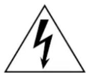
The lightning flash with arrowhead symbol within an equilateral triangle is intended to alert the user to the presence of uninsulated “dangerous voltage” within the product’s enclosure that may be of sufficient magnitude to constitute a risk of electric shock to persons.

The exclamation point within an equilateral triangle is intended to alert the user to the presence of important operating and maintenance (servicing) instructions in the literature accompanying the product.
IMPORTANT SAFETY INSTRUCTIONS
1 Read these instructions.
2 K eep these instructions.
3 Heed all warnings.
4 Follow all instructions.
5 Do not use this apparatus near water.
6 Clean only with dry cloth.
7 Do not block any ventilation openings. Install in accordance with the manufacturer's instructions.
8 Do not install near any heat sources such as radiators, heat registers, stoves, or other apparatus (including amplifiers) that produce heat.
9 Do not defeat the safety purpose of the polarized or grounding-type plug. A polarized plug has two blades with one wider than the other. A grounding type plug has two blades and a third grounding prong. The wide blade or the third prong are provided for your safety. If the provided plug does not fit into your outlet, consult an electrician for replacement of the obsolete outlet.
10 Protect the power cord from being walked on or pinched particularly at plugs, convenience receptacles, and the point where they exit from the apparatus.
11 Only use attachments/accessories specified by the manufacturer.
12 Use only with the cart, stand, tripod, bracket, or table specified by the manufacturer, or sold with the apparatus. When a cart is used, use caution when moving the cart/apparatus combination to avoid injury from tip-over.
13 Unplug this apparatus during lightning storms or when unused for long periods of time.
14 Refer all servicing to qualified service personnel. Servicing is required when the apparatus has been damaged in any way, such as power-supply cord or plug is damaged, liquid has been spilled or objects have fallen into the apparatus, the apparatus has been exposed to rain or moisture, does not operate normally, or has been dropped.

WARNING
TO REDUCE THE RISK OF FIRE OR ELECTRIC SHOCK, DO NOT EXPOSE THIS APPARATUS TO RAIN OR MOISTURE.
(UL60065_03)
PRECAUTIONS
PLEASE READ CAREFULLY BEFORE PROCEEDING
* Please keep this manual in a safe place for future reference.

WARNING
Always follow the basic precautions listed below to avoid the possibility of serious injury or even death from electrical shock, short-circuiting, damages, fire or other hazards. These precautions include, but are not limited to, the following:
Power supply/Power cord
- Only use the voltage specified as correct for the device. The required voltage is printed on the name plate of the device.
- Use only the included power cord.
If you intend to use the device in an area other than in the one you purchased, the included power cord may not be compatible. Please check with your Yamaha dealer. - Do not place the power cord near heat sources such as heaters or radiators, and do not excessively bend or otherwise damage the cord, place heavy objects on it, or place it in a position where anyone could walk on, trip over, or roll anything over it.
- Be sure to connect to an appropriate outlet with a protective grounding connection. Improper grounding can result in electrical shock.
Do not open
- Do not open the device or attempt to disassemble the internal parts or modify them in any way. The device contains no user-serviceable parts. If it should appear to be malfunctioning, discontinue use immediately and have it inspected by qualified Yamaha service personnel.
Water warning
- Do not expose the device to rain, use it near water or in damp or wet conditions, or place containers on it containing liquids which might spill into any openings. If any liquid such as water seeps into the device, turn off the power immediately and unplug the power cord from the AC outlet. Then have the device inspected by qualified Yamaha service personnel.
- Never insert or remove an electric plug with wet hands.
If you notice any abnormality
- If the power cord or plug becomes frayed or damaged, or if there is a sudden loss of sound during use of the device, or if any unusual smells or smoke should appear to be caused by it, immediately turn off the power switch, disconnect the electric plug from the outlet, and have the device inspected by qualified Yamaha service personnel.
- If this device should be dropped or damaged, immediately turn off the power switch, disconnect the electric plug from the outlet, and have the device inspected by qualified Yamaha service personnel.

CAUTION
Always follow the basic precautions listed below to avoid the possibility of physical injury to you or others, or damage to the device or other property. These precautions include, but are not limited to, the following:
Power supply/Power cord
- Remove the electric plug from the outlet when the device is not to be used for extended periods of time, or during electrical storms.
- When removing the electric plug from the device or an outlet, always hold the plug itself and not the cord. Pulling by the cord can damage it.
Location
- Before moving the device, remove all connected cables.
- When setting up the device, make sure that the AC outlet you are using is easily accessible. If some trouble or malfunction occurs, immediately turn off the power switch and disconnect the plug from the outlet. Even when the power switch is turned off, electricity is still flowing to the product at the minimum level. When you are not using the product for a long time, make sure to unplug the power cord from the wall AC outlet.
-
If this device is to be mounted in an EIA-standard rack, carefully read the section "Precautions for Rack Mounting" on page 7 before setting up the device. Inadequate ventilation can result in overheating, possibly causing damage to the device(s), or even fire.
-
Do not expose the device to excessive dust or vibrations, or extreme cold or heat (such as in direct sunlight, near a heater, or in a car during the day) to prevent the possibility of panel disfiguration or damage to the internal components.
- Do not place the device in an unstable position where it might accidentally fall over.
- Do not block the vents. This device has ventilation holes at the front and rear to prevent the internal temperature from becoming too high. In particular, do not place the device on its side or upside down. Inadequate ventilation can result in overheating, possibly causing damage to the device(s), or even fire.
- Do not use the device in the vicinity of a TV, radio, stereo equipment, mobile phone, or other electric devices. Doing so may result in noise, both in the device itself and in the TV or radio next to it.
- Do not place the device in a location where it may come into contact with corrosive gases or salt air. Doing so may result in malfunction.
Connections
- Before connecting the device to other devices, turn off the power for all devices. Before turning the power on or off for all devices, set all volume levels to minimum.
Handling caution Backup battery
- When turning on the AC power in your audio system, always turn on the power amplifier LAST, to avoid speaker damage. When turning the power off, the power amplifier should be turned off FIRST for the same reason.
- Condensation can occur in the device due to rapid, drastic changes in ambient temperature – when the device is moved from one location to another, or air conditioning is turned on or off, for example. Using the device while condensation is present can cause damage. If there is reason to believe that condensation might have occurred, leave the device for several hours without turning on the power until the condensation has completely dried out.
- Do not insert your fingers or hands in any gaps or openings on the device (vents, etc.).
- A void inserting or dropping foreign objects (paper, plastic, metal, etc.) into any gaps or openings on the device (vents, etc.) If this happens, turn off the power immediately and unplug the power cord from the AC outlet. Then have the device inspected by qualified Yamaha service personnel.
- Do not use the device for a long period of time at a high or uncomfortable volume level, since this can cause permanent hearing loss. If you experience any hearing loss or ringing in the ears, consult a physician.
- Do not rest your weight on the device or place heavy objects on it, and avoid use excessive force on the buttons, switches or connectors.
- This device has a built-in backup battery that maintains data in internal memory even when the device's power is switched off. The backup battery will eventually become depleted, however, and when that happens the contents of the internal memory will be lost.* To prevent loss of data be sure to replace the backup battery before it becomes fully depleted. Imminent battery depletion is indicated by the panel LEDs, as described on page 21. In this case, immediately save the data to a compatible digital mixer, then have qualified Yamaha service personnel replace the backup battery. The average life of the internal backup battery is approximately 5 years, depending on operating conditions.
* Data items maintained in the internal memory by the backup battery are as follows:
- internal head amplifier settings
XLR-type connectors are wired as follows (IEC60268 standard): pin 1: ground, pin 2: hot (+), and pin 3: cold (-).
Yamaha cannot be held responsible for damage caused by improper use or modifications to the device, or data that is lost or destroyed.
Always turn the power off when the device is not in use.
The performance of components with moving contacts, such as switches, and connectors, deteriorates over time. Consult qualified Yamaha service personnel about replacing defective components.
European models
Purchaser/User Information specified in EN55103-1 and EN55103-2.
Inrush Current: 50A
Conforms to Environments: E1, E2, E3 and E4
- The illustrations as shown in this manual are for instructional purposes only, and may be different from the ones on your equipment.
- EtherSound is a registered trademark of Digigram S.A.
- The company names and product names in this manual are the trademarks or registered trademarks of their respective companies.
* Specifications and descriptions in this owner's manual are for information purposes only. Yamaha Corp. reserves the right to change or modify products or specifications at any time without prior notice. Since specifications, equipment or options may not be the same in every locale, please check with your Yamaha dealer.
Contents
Foreword....6
SB168-ES Features....6
Firmware Updates 6
Connecting the AC Power Cable 6
Powering ON or OFF 7
Precautions for Rack Mounting....7
Recessed installation....7
Resetting the Unit to Initial Factory Condition (Initialization) 7
About EtherSound 8
EtherSound is 8
Daisy Chain and Ring Networks 8
Controls and Functions....10
Front Panel 10
Rear Panel....11
System Examples ......12
Daisy Chain Connection 12
Ring Connection 12
Setup....13
About the AVS-ESMonitor Software 13
Initial Setup Using the Quick Setup Function 13
Individual Parameter Settings (Control Page) 16
Setup Error Messages....17
Head Amp Control ....18
Control from a Digital Mixing Console 18
Control From the AVS-ESMonitor Application.... 18
Head Amplifier Parameters That Can be Monitored and Controlled 19
Troubleshooting....20
Troubleshooting....20
Messages 21
References....167
General Specification....167
Input/Output Characteristics 167
Electrical Characteristics 168
Dimensions 169
Compatible Host List....169
Included Accessories
- Owner's Manual
- A C Power Cable
Foreword
Thank you for choosing the Yamaha SB168-ES Stage Box. The SB168-ES is an Ether-Sound capable stage box with 16 analog inputs and 8 analog outputs. In order to take full advantage of the features and performance offered by the SB168-ES, be sure to read this owner's manual carefully before operation.
SB168-ES Features
■ Long-distance EtherSound Network Capability
Audio can be transferred over distances up to 100 meters* between devices via standard Ethernet cables using the EtherSound network protocol. The SB168-ES can be used as a general-purpose analog I/O box. Supported sampling rates are 44.1 kHz and 48 kHz (88.2 kHz and 96 kHz are not supported).
* Maximum practical distance may vary according to the cable used.
■ Remotely Controllable Internal Head Amplifiers
Internal head amplifier parameters can be remotely controlled from a compatible digital mixing console or from the AVS-ESMonitor application running on a computer.
■ Up to Four SB168-ES Units\* Can Be Used for Expanded I/O
Up to four SB168-ES units can be used to provide a total of 64 inputs and 32 outputs.
* The maximum number of units that can be used may depend on the digital mixing console used.
Firmware Updates
Two types of firmware are required: firmware for the SB168-ES unit itself, provided by Yamaha, and EtherSound firmware provided by AuviTran.
The SB168-ES firmware can be updated from a computer connected to the rear-panel NETWORK connector. Information about the latest versions and firmware downloads are available at the Yamaha pro audio website SB168-ES product page:
http://www.yamahaproaudio.com/products
The EtherSound firmware can be updated from a computer connected to the EtherSound connector.
Information about the latest versions and firmware downloads are available at the AuviTran website:
http://www.auvitran.com/
Connecting the AC Power Cable

- Before connecting the power cable, make sure that the power switches of all devices are turned OFF.
First connect the supplied power cable to the socket on the rear panel of the SB168-ES, then connect the AC plug to an appropriate AC power outlet (make sure the local supply voltage matches the rated AC voltage of the unit).
Powering ON or OFF

• To prevent loud noise bursts from the speakers when powering up the system, turn devices on in the following order: audio sources, SB168-ES, digital mixer, and finally power amplifiers. Reverse this order when turning the system off.
-
Press the [POWER] switch to turn the unit ON.
-
Press the [POWER] switch a second time to turn the unit OFF.

- The unit consumes a very small "standby" voltage even when the power switch is turned OFF. Be sure to unplug the AC power cable if the unit will not be used for an extended period of time.
- Rapidly turning the unit ON and OFF in succession can cause it to malfunction. After turning the unit OFF, wait for about 6 seconds before turning it ON again.
Precautions for Rack Mounting
This unit is rated for operation at ambient temperatures ranging from 0 to 40 degrees Celsius. When mounting the unit with other SB168-ES unit(s) or other device(s) in an EIA standard equipment rack, internal temperatures can exceed the specified upper limit, resulting in impaired performance or failure.
Always observe the following when rack mounting the unit:
- If three or more SB168-ES units are mounted without space in the same rack, set the fan speeds to HIGH.
- If multiple SB168-ES units are mounted in the same rack with their fan speeds set to LOW, leave a 1U rack space between every two units. Also either leave the open spaces uncovered or install appropriate ventilating panels to minimize the possibility of heat buildup.
- When mounting the unit in a rack with devices such as power amplifiers that generate a significant amount of heat, leave more than 1U of space between the SB168-ES and other device. Also either leave the open spaces uncovered or install appropriate ventilating panels to minimize the possibility of heat buildup.
- To ensure sufficient airflow, leave the rear of the rack open and position it at least 10 centimeters from walls or other surfaces. If the rear of the rack can't be left open, install a commercially available fan or similar ventilating option to secure sufficient airflow. If you've installed a fan kit, there may be cases in which closing the rear of the rack will produce a greater cooling effect. Refer to the rack and/or fan unit manual for details.
Recessed installation
If you want to recess the front panel surface of the device from the front edge of the rack, you can adjust the position of the rack mount brackets to recess the device by 50mm or 100mm.
NOTE • When you install the brackets, use the same screws that you just removed.
Resetting the Unit to Initial Factory Condition (Initialization)
This operation initializes the internal backup memory, resetting all head amplifier parameters to the original factory settings.
- Turn the power OFF.
- Move front-panel DIP switches 6 and 8 down to the ON position, then turn the power ON.
Initialization will take about one second.
When initialization is complete all [PEAK] indicators on the front panel will flash. At the same time the OUT [TX]/IN [RX] indicators will flash and the IN [TX] indicator will light.
- Turn the power OFF, return DIP switches 6 and 8 to their original positions, then turn the power ON again.

EtherSound is ...
EtherSound is an audio networking protocol developed by Digigram in France. EtherSound allows up to 64 channels of uncompressed 24 bit/48 kHz audio to be bi-directionally transferred – 64 channels downstream plus 64 channels upstream – over a single CAT5e Ethernet cable. Up to 32 channels of 24 bit audio can be transferred when the sample rate is 96 kHz. Remote control signals for head amplifiers and other devices can be transferred simultaneously with the audio signals.
Signals can be transferred over distances of up to 100 meters* between devices. Even greater distances can be covered if media converters are used to convert the signals to optical fiber format.
* Dependent on cable quality. Refer to the website listed below for details. http://www.ethersound.com/
Latency when transferring 48 kHz signals is 5 samples (104 µ sec), increasing by 1.4 µ sec for each device added to the network (including network switches). EtherSound is the ideal choice for systems in which minimal latency is a priority.
The AVS-ESMonitor software application for Windows platforms that allows setup and monitoring of devices connected to an EtherSound network is available from the AuviTran website at no charge.
http://www.auvitran.com/
Daisy Chain and Ring Networks
The most basic type of connection used for EtherSound networks is the serial “Daisy Chain.” Daisy chain networks allow 64 channels of audio to be independently transferred in both the downstream and upstream directions simultaneously. In this case the top device in the chain is the word clock master, known as the “Primary Master.”

flowchart
graph TD
    A["Computer"] -->|IN| B["EtherSound Device"]
    B -->|OUT IN| C["EtherSound Device"]
    C -->|OUT IN| D["EtherSound Device"]
    D -->|Upstream: 64 Channels| E["Downstream: 64 Channels"]
    B <--> C
    C <--> D
    style A fill:#f9f,stroke:#333
    style B fill:#ccf,stroke:#333
    style C fill:#ccf,stroke:#333
    style D fill:#ccf,stroke:#333
It is also possible to use network switches to distribute the signals to multiple devices. In this case devices connected directly to the network switch cannot send signals in the upstream direction.

flowchart
graph TD
    A["EtherSound Device"] -->|OUT| B["Network Switch"]
    B --> C["Inner: EtherSound Device"]
    B --> D["Inner: EtherSound Device"]
    B --> E["Inner: EtherSound Device"]
    B --> F["Inner: EtherSound Device"]
    B --> G["Inner: EtherSound Device"]
    style A fill:#f9f,stroke:#333
    style B fill:#ccf,stroke:#333
    style C fill:#cfc,stroke:#333
    style D fill:#cfc,stroke:#333
    style E fill:#cfc,stroke:#333
    style F fill:#cfc,stroke:#333
    style G fill:#cfc,stroke:#333
If a connection is broken in a daisy chain network, the signal flow is interrupted at that point and no signal will be transferred beyond that point. This weakness can be overcome by connecting the ends of a daisy chain network to form a ring that provides signal redundancy. In this type of “Ring” network a problem at one point in the network will not affect operation of the entire network. The compromise is that ring networks are limited to a total of 64 audio channels. It is also necessary to use Ether-Sound devices that support ring network connection (the SB168-ES does support ring networks). Network switches and similar devices cannot be used in a ring network.

flowchart
graph LR
    A["EtherSound Device"] -->|OUT ININ OUT OUTIN| B["EtherSound Device"]
    B --> C["EtherSound Device"]
    C --> D["Out"]
    D --> A
    style A fill:#f9f,stroke:#333
    style B fill:#f9f,stroke:#333
    style C fill:#f9f,stroke:#333
    style D fill:#f9f,stroke:#333
NOTE • For detailed information on EtherSound, refer to the EtherSound website: http://www.ethersound.com/, and the "EtherSound Setup Guide" at the Yamaha pro audio website SB168-ES product page: http://www.yamahaproaudio.com/products/
Front Panel

① INPUT 1–16 Connectors
These are the XLR-3-31 type analog connectors for the 16 input channels. The input level range is from -62 dBu to +10 dBu. +48V phantom power can be supplied to devices that require it via the input connectors.
NOTE
- The PAD will be switched on or off internally when the gain of the SB168-ES internal head amp is adjusted between -14 dB and -13 dB. Keep in mind that noise may be generated if there is a difference between the Hot and Cold impedance of the external device connected to the INPUT connector when using phantom power.
② +48V Indicators
These indicators light when +48V phantom power is turned ON for the corresponding input channels. Phantom power supply switching can be carried out from a compatible digital mixing console or computer application. No phantom power will be supplied, however, if the [+48V MASTER] switch is OFF, even if phantom power to individual channels is turned ON (the +48V indicators will still light). The +48V indicators also function as error indicators: the indicators for all channels will flash if an error occurs.

- Make sure that phantom power is turned OFF unless it is needed.
- When turning phantom power ON, make sure that no equipment other than phantom-powered devices such condenser microphones are connected to the corresponding INPUT connectors. Applying phantom power to a device that does not require phantom power can damage the device.
- Do not connect or disconnect a device to an INPUT while phantom power is applied. Doing so can damage the connected device and/or the unit itself.
- To prevent possible damage to speakers, make sure that power amplifiers and/or powered speakers are turned OFF when switching phantom power ON or OFF. We also recommend setting all digital mixing console output controls to minimum when turning phantom power ON or OFF. Sudden high level peaks caused by the switching operation can damage equipment as well as the hearing of those present.
③ SIG Indicators
These indicators light green when the signal applied to the corresponding channel reaches or exceeds -34 dBFS. The SIG indicators also function as error indicators: the indicators for all channels will flash if an error occurs.
④ PEAK Indicators
These indicators light red when the signal level of the corresponding channel reaches or exceeds -3 dBFS. The PEAK indicators also function as error indicators: the indicators for all channels will flash if an error occurs (and during initialization).
⑤ EtherSound [IN]/[OUT] Connectors
The SB168-ES can be connected to other EtherSound devices via these RJ-45 connectors using standard Ethernet cables (CAT5e or better recommended). [IN] and [OUT] connectors are provided to allow daisy chain or ring connection.
NOTE
- The use of Ethernet cables with Neutrik etherCON® CAT5 compatible RJ-45 plugs is recommended. Standard RJ-45 plugs can also be used.
- Use STP (shielded twisted pair) cable to prevent electromagnetic interference. Make sure that the metal parts of the plugs are electrically connected to the STP cable shield by conductive tape or comparable means.
- Refer to the following EtherSound website for the length of cable that can be used. http://www.ethersound.com/
⑥ IN/OUT [TX]/[RX] Indicators
The appropriate indicator flashes when data is transmitted from (TX) or received at (RX) the EtherSound [IN]/[OUT] connectors.
These indicators will also light and/or flash to display errors, warnings, and information as described on page 21.
NOTE
- All four indicators will flash when the [Identify] button in the AVS-ESMonitor application (page 16) is clicked, and will continue to flash until the button is clicked a second time.
⑦ DIP Switches 1–8
Switches 1–4 of this 8-bit DIP switch are used to set the Setup ID as described on page 14.
⑧ [+48V MASTER] Switch
This is the master switch for the unit's +48V phantom power supply. If the [+48V MASTER] switch is off no phantom power will be supplied to the unit's input connectors even if the individual input phantom power settings are ON. However, the +48 indicators will light on channels for which phantom power is turned ON even if the [+48V MASTER] switch is OFF.
9 Power Indicator
Lights when AC power to the unit is ON.
⑩ [POWER] Switch
Turns power to the unit ON or OFF. Internal head amplifier settings such as gain, high-pass filter, etc., are retained in memory even when the power is OFF.
⑪ OUTPUT 1–8 Connectors
These eight XLR-3-32 type connectors deliver analog output from the unit's corresponding output channels. Nominal output level is +4 dBu.
Rear Panel

① Earth Screw
For maximum safety, please earth the unit properly. The supplied AC power cable is a 3-wire type, so if the AC outlet used is properly earthed the SB168-ES will be earthed as well. If the AC outlet used is not earthed, however, please use the earth screw to earth the unit. In addition to maximizing safety, proper earth connection also effectively minimizes hum and interference.
② [AC IN] Socket
Connect the supplied AC power cable here. First connect the AC power cable to the socket on the SB168-ES rear panel, then plug it into an appropriate AC power outlet.
![YAMAHA SB168-ES - ② [AC IN] Socket - 1](/content/2026/05/912888/images/acc405734807651cf627fe10f2c2a72b904150dfc8bc966a229fe818bde2c418.jpg)
- Use only the supplied AC power cable. The use of an inappropriate cable can result in equipment failure, overheating, or even fire.
③ NETWORK Connector
An Ethernet cable can be connected from a computer to this connector to allow updating the unit's firmware.
NOTE
- Use STP (shielded twisted pair) cable to prevent electromagnetic interference (USA, Canada, and Europe).
- Since the SB168-ES supports MDI/MDI-EX, either a straight or cross Ethernet cable can be used.
④ [FAN] Switch
Sets the internal cooling fan to operate at either HIGH or LOW speed. This switch is set to LOW when the unit is initially shipped from the factory. As long as the unit is operated within the specified ambient temperature range either the LOW or HIGH setting can be used. The HIGH setting is recommended if the ambient temperature is high, if the unit is in direct sunlight even if the ambient temperature is within the specified operating range, and in any situation in which fan noise is not a problem.
If two or more SB168-ES units are mounted in the same rack and the fan speed is set to LOW, leave a 1U rack space between every two units. Also either leave the open rack spaces uncovered or install appropriate ventilating panels to minimize the possibility of heat buildup. If three or more SB168-ES units are mounted without space in the same rack, set the fan speeds to HIGH.
Daisy Chain Connection
In this example an MY16-ES64 EtherSound interface card is installed in a Yamaha M7CL or LS9 digital mixing console and connected to multiple SB168-ES units. In this type of system an MY16-EX I/O expansion card is also required for each additional SB168-ES unit connected in the daisy chain (i.e. for three SB168-ES units one MY16-ES64 card and two MY16-EX cards are required).
The EtherSound [OUT] connector on the MY16-ES64 card is connected to the [IN] connector of the first SB168-ES unit, and subsequent units are daisy chained as shown in the diagram. A computer can be connected to the EtherSound [IN] connector on the MY16-ES64 card functioning as Primary Master.

flowchart
graph TD
    A["Computer"] --> B["My16-ES64"]
    B --> C["Yamaha Mixing Console"]
    C --> D["OutIN"]
    C --> E["MY16-EX"]
    C --> F["EtherSound"]
    D --> G["SB168-ES (ID #1)"]
    E --> H["SB168-ES (ID #2)"]
    F --> I["SB168-ES (ID #3)"]
    G --> J["Inputs: CH 1–16"]
    H --> K["Inputs: CH 17–32"]
    I --> L["Inputs: CH 33–48"]
    J --> M["Outputs: CH 1–8"]
    K --> N["Outputs: CH 9–16"]
    L --> O["Outputs: CH 17–24"]
Daisy Chain Characteristics
- F our daisy chained SB168-ES units provide a total of 64 input channels and 32 output channels.
- The computer can remain connected at all times, making it possible to use the AVS-ESMonitor application to control the SB168-ES head amplifiers and continuously monitor the EtherSound network.
- If a connection is broken in a daisy chain network, the signal flow is interrupted at that point and no signal will be transferred beyond that point.
Ring Connection
As in the daisy chain example above, an MY16-ES64 EtherSound interface card is used to connect the digital mixing console to the SB168-ES units. The EtherSound [OUT] connector is connected to the EtherSound [IN] connector of the subsequent unit, and the EtherSound [OUT] connector of the final SB168-ES unit is connected back to the EtherSound [IN] connector of the MY16-ES64 card.

flowchart
graph TD
    A["My16-ES64"] -->|EtherSound| B["Yamaha Mixing Console"]
    C["OUTIN"] --> B
    D["MY16-EX"] --> B
    E["Outer Network"] --> F["SB168-ES (ID #1)"]
    E --> G["SB168-ES (ID #2)"]
    E --> H["SB168-ES (ID #3)"]
    I["Outer Network"] --> J["SB168-ES (ID #1) Inputs: CH 1–16 Outputs: CH 1–8"]
    K["Outer Network"] --> L["SB168-ES (ID #2) Inputs: CH 17–32 Outputs: CH 9–16"]
    M["Outer Network"] --> N["SB168-ES (ID #3) Inputs: CH 33–48* Outputs: None*"]
    O["Outer Network"] --> P["OutIN IN"]
    Q["Outer Network"] --> R["OutIN OUT"]
    S["Outer Network"] --> T["OutIN IN"]
    U["Outer Network"] --> V["OutIN OUT"]
    W["Outer Network"] --> X["OutIN IN"]
    Y["Outer Network"] --> Z["OutIN OUT"]
    style A fill:#f9f,stroke:#333
    style C fill:#f9f,stroke:#333
    style D fill:#f9f,stroke:#333
    style E fill:#f9f,stroke:#333
    style F fill:#ccf,stroke:#333
    style G fill:#ccf,stroke:#333
    style H fill:#ccf,stroke:#333
    style I fill:#ccf,stroke:#333
    style J fill:#ccf,stroke:#333
    style K fill:#ccf,stroke:#333
    style L fill:#ccf,stroke:#333
    style M fill:#ccf,stroke:#333
    style N fill:#ccf,stroke:#333
    style O fill:#ccf,stroke:#333
    style P fill:#ccf,stroke:#333
    style Q fill:#ccf,stroke:#333
    style R fill:#ccf,stroke:#333
Ring Connection Characteristics
- The EtherSound specifications limit the total number of input and output channels to 64 in this type of network.
- The AVS-ESMonitor application cannot be used during system operation. An EtherSound device with a third port is required to connect a computer running AVS-ESMonitor into the ring.
- A problem at one point in the network will not affect operation of the entire network.
NOTE • In ring connections it is particularly important to ensure that all EtherSound devices are running the latest firmware (page 6).
About the AVS-ESMonitor Software
AVS-ESMonitor is a software application from the Auvitran company that allows monitoring and control of EtherSound networks. It can be used to make input/output assignments and set the EtherSound parameters as required. Please download the AVS-ESMonitor application from the website listed below. AVS-ESMonitor versions 3.4.6 and later support the SB168-ES.
http://www.auvitran.com/
Initial SB168-ES setup can be performed quickly and easily using the AVS-ESMonitor Quick Setup function. The Quick Setup function provides the following capabilities:
- Sets up necessary EtherSound settings for the SB168-ES and MY16-ES64. EtherSound devices other than the SB168-ES and MY16-ES64 are not affected, but patches to those other EtherSound devices will be cleared.
- Support for up to four SB168-ES units connected to an MY16-ES64.
- The Quick Setup function cannot be used if two or more MY16-ES64 cards are connected to the network. To connect multiple SB168-ES units, add one MY16-EX card for each additional SB168-ES unit added to the network (an MY16-EX card is not required for the first or only SB168-ES unit in a network).
- After the Quick Setup function is executed, as long as the network connections are not changed there is no need to perform the Quick Setup procedure again. However, if the number and/or order of the SB168-ES units are changed, or the connected devices (SB168-ES, MY16-ES64) are replaced, it will be necessary to perform the Quick Setup operation again.
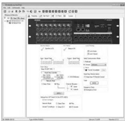
The Quick Setup function cannot be used when EtherSound cards from other manufacturers are used. In such a case the necessary initial parameters must be set up manually: refer to "Individual Parameter Settings (Control Page)" on page 16 for details. When connecting with the M7CL-48ES, the Auto Configure function can apply the patch settings automatically without the AVS-ESMonitor application. The latest firmware for the SB168-ES will be required in this case.
Initial Setup Using the Quick Setup Function
Preparation
- Determine the source for head amplifier parameter control:
A. MY16-ES64 Slot Internal Connection (LS9) Use this option is for digital mixing consoles such as the LS9 that don't have a 9-pin D-sub "HA REMOTE" connector.
B. MY16-ES64 D-sub 9-pin Connection Use this option for digital mixing consoles such as the M7CL or digital mixing engines such as the DME64N or DME24N that have a 9-pin D-sub "HA REMOTE connector.
C. AVS-ESMonitor
NOTE • Refer to page 169 to determine whether your digital mixing console can be used to control the SB168-ES.
-
Turn the power to all devices OFF.
-
Set the switches on the MY16-ES64 and MY16-EX circuit boards.

flowchart
graph TD
    A["Device 0.05"] --> B["Switch"]
    B --> C["MY16-ES64"]
    B --> D["SW1 SW2"]
    B --> E["MY16-EX"]
    E --> F["SW1 SW2"]
- If you selected option B in step 1, set the SW1 switch on the MY16-ES64 to [422].
- Set the SW2 switch on the MY16-ES64 to [48K].
- When one or more MY16-EX cards are to be used, SW1 on the MY16-EX sets the ID number. ID numbers should be assigned in sequence, corresponding to the order the cards are to be connected to the MY16-ES64.
- Set the SW2 switches on all MY16-EX cards to [48K].
- Install the MY16-ES64 and MY16-EX cards in the digital mixing console's slots, then connect the required Ethernet cables.
NOTE • F or details on installing and connecting the cards, refer to instructions provided with each product. • When installing an MY16-ES64 card in an LS9-32 console, install the card in SLOT 1.
- Set the ID of each SB168-ES unit via the DIP switches (1–4) in the order they are connected, taking care not to duplicate any of the ID settings.

The DIP switch corresponding to the desired ID number should be moved to it's "down" (ON) position. All other switches should remain in their "up" positions.
- Make the required daisy chain connections between the MY16-ES64 card and the SB168-ES units.
NOTE • When setting up a ring type network, initial settings should be made with the system connected as a daisy chain. Close the ring connection after the initial settings have been made.
- Connect the computer to the MY16-ES64 EtherSound [IN] connector.
- If you selected option B in step 1, connect the digital mixing console's [REMOTE] connector to the MY16-ES64 card [HA REMOTE] connector via a 9-pin D-sub cross cable.
- Turn the power to all devices ON.
- Select the word clock master on the digital mixing console. For a daisy chain network select either [INT48K] or [INT44.1K], and for a ring network select the [1/2] channel of the slot in which the MY16-ES64 card is installed.
- If you selected option A in step 1, and are using an LS9-32 console, select [SLOT 1] via the console's EXTERNAL HA display COMM PORT parameter.
Setup Procedure
- Launch the AVS-ESMonitor application in online mode.
NOTE • If the AVSMonitor application has been launched in offline mode, it can be switched to online mode by clicking [Switch offline mode] in the [Command] menu.
- Click [Reset networks] in the [Command] menu.
- In the tree views select one of the SB168-ES units on the network.
- Open the Control tab.

- Select the control source determined in the previous section via the Quick Setup Head Amp Controller field.

- Select the EtherSound network connection type via the Network Mode field.

flowchart
graph TD
    A["Network Mode"] --> B["Daisy Chain"]
    A --> C["Ring"]
    D["Channel Allocation"] --> E["48 Inputs"]
    D --> F["16 Outputs"]
- If a ring network is to be used, use the Channel Allocation slider to select an input/output channel combination. The possible combinations are as follows:
| Inputs(No. of Input Channels) | 32 40 48 56 64 | ||
| Outputs(No. of Output Channels) | 32 24 16 8 0 |
In ring networks the total number of input and output channels is limited to 64. If the network includes only one or two SB168-ES units you can select from 32 Inputs/32 Outputs to 48 Inputs/16 Outputs without exceeding the limitation. If three or four SB168-ES units are connected you will need to decide whether to give priority to inputs or outputs. For example, you could select 64 Inputs/0 Outputs if you want to use all available input channels, or 32 Inputs/32 Outputs if you want to use all available output channels.
-
Click the [APPLY] button, then click the [OK] button in response to the confirmation dialog that appears.
-
If the Quick Setup operation has completed successfully a "Quick Setup is done successfully" message will appear.
The Quick Setup fields will return to their initial state when the Quick Setup operation has finished.
- If you are setting up a ring network, disconnect the computer from the MY16-ES64 card EtherSound [IN] connector, and connect the EtherSound [OUT] connector on the last SB168-ES unit in the chain back to the EtherSound [IN] connector on the MY16-ES64 card to complete the ring.
When four SB168-ES units are daisy chained, their input channels are assigned to MY16-ES64 input channels 1–64 in order from the first SB168-ES unit in the chain (Setup ID #1) as follows: 1–16, 17–32, 33–48, 49–64. The MY16-ES64 output channels are assigned to the SB168-ES outputs in the same way: 1–8, 9–16, 17–24, 25–32.
In a ring network the input and output channels are assigned in sequence from the first to last SB168-ES unit within the maximum 64-channel limitation, according to the number of SB168-ES units used and the Channel Allocation setting.
NOTE
- As long as the network connections are not changed there is no need to perform the Quick Setup procedure again. However, if the number and/or order of the SB168-ES units are changed, or the connected devices (SB168-ES, MY16-ES64) are replaced, it will be necessary to perform the Quick Setup operation again.
- If other types of EtherSound devices are connected, or the channel assignments are to be changed, it will be necessary to set the appropriate parameters individually via the AVS-ESMonitor application. Refer to "Individual Parameter Settings (Control Page)" on page 16 and/or the AVS-ESMonitor operation manual for details.
- Set up the digital mixing console input patching in sequential 8-channel groups for the slot inputs (CH1–8, CH9–16, etc.). This makes it easy to select input channels on the external SB168-ES units for remote head amplifier control.
- When the Quick Setup function is executed the settings are saved to non-volatile memory in EtherSound devices on the network, overwriting any previous data. Since the previous data is overwritten and thereby erased, you might want to save important settings before executing the Quick Setup function via the [Save As] command in the [File] menu.
Individual Parameter Settings (Control Page)
When connecting to devices that are not supported by the Quick Setup function, or when you need to make changes to specific EtherSound settings, the parameters in the AVS-ESMonitor Control page provide access to head amplifier control settings while those in the Net Patch and I/O Patch pages provide access to the input an output channel settings. Refer to the AVS-ESMonitor manual for details on the Net Patch and I/O Patch pages.

Synchro Status
Displays the current EtherSound network synchronization status.
Error Status
Displays SB168-ES error messages. The indicators on the SB168-ES indicate the type of error by the way they flash or light, while specific error messages are displayed here.
Lock Routing
This parameter makes it possible to temporarily lock editing of the patches in the I/O Patch page, preventing possible operation errors. "Lock Inputs" locks the IN > ES patches, while "Lock Outputs" locks the OUT < ES patches.
Input Signal Peak/Output Signal Peak
Signal and peak indicators for the input and output channels. The upper row is the PEAK indicators, which light red, and the lower row is the SIGNAL indicators, which light green.
Serial Communication Mode
Select [Unicast] when controlling the head amplifiers from a compatible digital mixing console, and select the MY16-ES64 card as the communication target. It is also necessary to set the MY16-ES64 Serial Communication Mode.
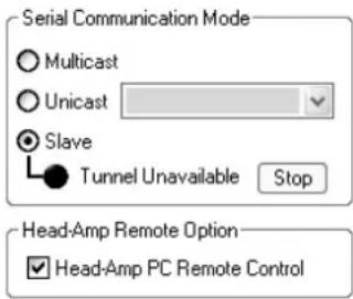
Select [Slave] when controlling the head amplifiers directly from the AVS-ESMonitor application.
The [Multicast] setting is provided for future expansion, and is not currently available.
Head Amp Remote Option
When controlling the head amplifiers from the AVS-ESMonitor application, a Head Amp page that provides access to the head amplifier control parameters will be added to the interface if the [Head Amp PC Remote Control] checkbox is checked after selecting [Slave] in the Serial Communication Mode section.
Tools
When the [Identify] button is clicked the SB168-ES IN/OUT [TX]/[RX] indicators will flash, and will continue to flash until the button is clicked a second time.
Emergency Clock
If the EtherSound network is used in a ring configuration, turn this checkbox ON to prevent audio interruptions when a connection in the ring is broken. If Emergency Clock is OFF, audio will be interrupted.
For daisy chain configurations, if the SB168-ES is the primary master, turn this checkbox OFF to select the SB168-ES internal word clock or ON to use the EtherSound module word clock. If the SB168-ES is not primary master, the Emergency Clock checkbox has no effect.
NOTE • See page 13 for information on the Quick Setup function.
Settings from DIP Switch 5-8 (for M7CL-48ES)
These are the settings for use when connecting with the M7CL-48ES using the Auto Configure function. The settings of "Network Mode" and "Unicast Tunneling to" are displayed by scanning the status of the DIP switches 5–8 when the power is turned ON.
When you want to temporarily change the EtherSound settings (including "Network Mode" and "Unicast Tunneling to") in the AVS-ESMonitor application, turn the Auto Configure checkbox OFF.
Setup Error Messages
If any of the error messages listed below appears while executing the Quick Setup function, resolve the problem as required and then execute Quick Setup again.
When changing a Setup ID setting be sure to turn the device's power OFF, change the DIP switch settings as required, and then turn the device ON again.
| Error Message Details and Solution | |
| Setup ID is discontinuous. Setup ID #n not found. | The Setup ID numbers are not sequential—ID “#n” is missing.Referring to the “Preparation” instructions on page 13, use the DIP switches to set the Setup ID numbers in sequence beginning from #1. |
| There are two or more with same Setup ID #n. (flashing) | Two or more SB168-ES units have the same Setup ID number.When duplicate Setup ID numbers are detected the SB168-ES IN/OUT [TX]/[RX] indicators will flash. Referring to the “Preparation” instructions on page 13, check the DIP switch settings and make sure that each unit has a unique Setup ID. |
| There are two or more MY16-ES64(s). (flash-ing) | Two or more MY16-ES64 cards have been detected on the EtherSound network.The use of two or more MY16-ES64 cards is not supported by the Quick Setup function. The IN/OUT [TX]/[RX] indicators of the MY16-ES64 cards will flash. Redo the connections so that only one MY16-ES64 is connected to the network. |
| MY16-ES64 is not found in ES network. No MY16-ES64 card can be located on the EtherSound network.EtherSound interface cards other than the MY16-ES64 are not supported by the Quick Setup function. | |
| MY16-ES64 is not Primary Master. (flashing) | The MY16-ES64 is not functioning as Primary Master in a daisy chain network.This type of configuration is not supported by the Quick Setup function. The IN/OUT [TX]/[RX] indicators of the MY16-ES64 card will flash while this error message is displayed. Redo the connections so that the MY16-ES64 functions as Primary Master. |
| Setup ID of all SB168-ES is not assigned. | The Setup ID has not been set for any of the SB168-ES units on the EtherSound network. The Setup ID for at least one unit must be set.The IN/OUT [TX]/[RX] indicators of the SB168-ES units will flash while this error message is displayed. Referring to the “Preparation” instructions on page 13, set the Setup ID numbers of the connected SB168-ES units.No error will occur if the Setup ID is not set for one of the SB168-ES units in a multi-unit system, but the patch settings for that SB168-ES unit will be cleared. |
| MY16-ES64 is not 48kHz. 96kHz is selected. | The sampling frequency of the MY16-ES64 card connected to the EtherSound network is set to 96 kHz (SW2).The SB168-ES does not support 88.2 kHz or 96 kHz sampling frequencies.The IN/OUT [TX]/[RX] indicators of the MY16-ES64 card will flash while this error message is displayed. Referring to the “Preparation” instructions on page 13, set the SW2 switch on the MY16-ES64 card to [48K]. |
| The power supply was turned off or the cable was disconnected. | The power to one of the devices connected to the EtherSound network was turned off, or a cable was disconnected during Quick Setup execution.Check the power cables and power switch settings of all devices and execute the Quick Setup function again. |
| Audio routing locked on device. (flashing) | The Quick Setup function cannot be executed if the Lock Routing parameter in the Control page is ON.The IN/OUT [TX]/[RX] indicators of the MY16-ES64 card and SB168-ES units will flash while this error message is displayed.In order to execute the Quick Setup function all Lock Routing parameters must be turned OFF. |
The SB168-ES head amplifiers can be remotely controlled from host devices such as a compatible digital mixing console or digital mixing engine (see page 169), or from the AVS-ESMonitor application.
Control from a Digital Mixing Console
The SB168-ES head amplifiers can be controlled from a compatible digital mixing console. In order to control the head amplifiers from a digital mixing console, select control via an MY16-ES64 in the Quick Setup Head Amp Controller field.
Each SB168-ES unit will be represented by two AD8HR units (AD8HR #1, AD8HR #2, etc.) on the digital mixing console display, and the SB168-ES parameters can be controlled in the same way as AD8HR parameters. Furthermore, scene recall can be used to recall all head amplifier settings at once.
Refer to the digital mixing console owner's manual for details on head amplifier control.
| Model Section Title | in Owner’s Manual |
| M7CL, LS9 Using an external head | amp |
| DM1000 Using the AD8HR/AD824 | |
| DM2000 Controlling AD8HR/AD824 | A/D Converters |
| PM5D/PM5D-RH Reference section | SYS/W.CLOCK function—HA (Head Amp) screen |
| DME64N/24N Controlling external | head amplifiers from the DME64N/24N, Head Amplifier Setup (HA) Page |
NOTE • SB168-ES error messages are not shown on the digital mixing console display, and EtherSound parameters cannot be set from the digital mixing console. Use the AVS-ESMonitor software application for these functions.
Control From the AVS-ESMonitor Application
The AVS-ESMonitor application can be used both to set EtherSound parameters and control the SB168-ES head amplifiers. To control the head amplifiers from the AVS-ESMonitor application, either select AVS-ESMonitor in the Quick Setup Head Amp Controller field or perform the setup procedure described below and a Head Amp page will be added to the AVS-ESMonitor interface.
- Select the SB168-ES to be controlled in the tree views.
NOTE • If multiple SB168-ES units are to be controlled, repeat the procedure described below for each one.
- Select [Slave] in the Serial Communication mode section.
Check each Control page and make sure that no other EtherSound device is assigned to transmit to this SB168-ES unit. If the SB168-ES is selected, temporarily switch to the [Slave] setting.
- Check the [Head Amp PC Remote Control] Checkbox.
A Head Amp tab will appear.
4. Click the Head Amp Tab.
It can take a few seconds for the channel name in the Ch Selection field to appear.

The head amplifier parameters can be controlled from this display. The current parameter settings will be shown on the display when "ch 1-8" or "ch 9-16" is selected from the Ch Selection filed.
NOTE
- If you later decide to switch back to controlling the head amplifiers from a digital mixer, we recommend executing the Quick Setup function again, although the same result can be achieved by un-checking the [Head Amp PC Remote Control] checkbox and setting the Serial Communication Mode to [Unicast] (via an MY16-ES64).
- The AVS-ESMonitor application cannot be used while a ring network is in operation. In order to use the AVS-ESMonitor application to control the head amplifiers it is necessary to either switch to a daisy chain configuration or add an EtherSound device with a third-port to the system.
- The on-screen head amplifier controls can be operated both by click-and-drag and via the mouse scroll wheel.
Head Amplifier Parameters That Can be Monitored and Controlled
| Parameter Description | |
| +48V Turns +48V phantom power ON or OFF | for each channel. |
| HA GAIN Adjusts gain from -62 dB to +10 dB in 1-dB increments. | |
| HPF Turns the high-pass filter ON or OFF. | |
| HPF FREQ | Adjusts the cutoff frequency of the high-pass filter (12 dB/Oct.) from 20 Hz to 600 Hz in 60 steps. |
| METER Displays a level meter for each input channel. | |
| Device ID | Displays the automatically assigned device ID numbers 1–8 (corresponding to AD8HR device ID numbers). Two ID numbers are assigned to each SB168-ES unit. |
| +48V Master SW Displays the master ON/OFF | status of the +48V phantom power supply. |
NOTE
- Sound output may be briefly interrupted when adjusting gain, but this is normal. Since the gain is being internally adjusted in 6-dB steps, output is briefly muted to prevent noise.
- The following parameters are not supported and cannot be edited even if shown on the display: Device Mode/Name, Word Clock Source, Gain trim, Panel Lock, LED Brightness
Troubleshooting
| Symptom Possible Solution | |
| The power won't turn on. The power indicator doesn't light. | Is the power cable connected properly? (page 6)Is the [POWER] switch properly engaged? (page 7)If you've checked all possible causes and the power still won't come on, refer the problem to your Yamaha dealer. |
| The unit is not receiving an input signal. • Are the input cables properly connected?Are the source devices delivering an appropriate signal? Check the SIG indicators on the appropriate channels.Have you executed the Quick Setup function? Did you change any patch settings via the AVS-ESMonitor application after executing the Quick Setup function?Are the AVS-ESMonitor patch settings appropriate (Net Patch or I/O Patch page)?Is the head amplifier gain set to an appropriate level? | |
| The input level is too low. • If a condenser microphone is being used, is the [+48V MASTER] switch ON?If a condenser microphone is being used, is phantom power for the corresponding channel(s) turned ON?Is the head amplifier gain set to an appropriate level? | |
| No output. • Are the output cables properly connected?Have you executed the Quick Setup function? Did you change any patch settings via the AVS-ESMonitor application after executing the Quick Setup function?Are the AVS-ESMonitor patch settings appropriate (Net Patch or I/O Patch page)?Is output muted at the digital mixing console? | |
| An error message is displayed during Quick Setup. | Refer to page 17 for information on error messages that might be displayed during execution of the AVS-ESMonitor Quick Setup function. |
| Head amplifier remote control isn't working. | Did you make the appropriate Head Amp Controller setting when executing the Quick Setup function? Did you change the Serial Communication Mode setting after executing the Quick Setup function?Is the AVS-ESMonitor Serial Communication Mode set properly? (page 16)If you will be controlling the head amplifiers via the 9-pin D-sub REMOTE connector on a digital mixing console, is the mixing console's REMOTE connector properly connected to the HA REMOTE connector on the MY16-ES64 card (Primary Master)? (page 14)If you will be controlling the head amplifiers via a mixing console expansion slot, is the EXTERNAL HA display COMM PORT parameter set appropriately? (page 14)Set up the digital mixing console input patching in sequential 8-channel groups for the slot inputs (CH1–8, CH9–16, etc.). This makes it easy to select input channels on the external SB168-ES units for remote head amplifier control. |
| Can't control the SB168-ES by the M7CL-48ES. | Is the Stage Box Setup function of the M7CL-48ES set properly?Did you correctly set the DIP switches before turning on the power to the devices?Has the firmware been updated to an appropriate version? |
| • Can't execute Quick Setup in the AVS-ESMonitor• Can't change Serial Communication Mode in the AVS-ESMonitor | Is the AUTO CONFIGURE button for the Stage Box Setup function turned off?Are DIP switches 5–8 for the SB168-ES set to OFF (upper position)? |
Messages
Errors, warnings, and certain other types of information are displayed via the SB168-ES panel indicators. Messages are also displayed in the AVS-ESMonitor Error Status field.
Error Messages
When an error occurs the indicators for channels 1 through 16 will flash until the error is resolved, and the IN/OUT [TX]/[RX] will light and/or flash as shown in the chart below. If repair is required contact your Yamaha dealer.
| Indicators | AVS-ESMonitor Error Status | Details Solution | |
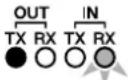 on flash on flash | No Battery! The backup battery is almost completely depleted, and there is a possibility that the stored settings will be lost. | If you turn off the power at this point there is a possibility that all current settings will be lost and the unit will be initialized. Stop using the unit immediately and contact your Yamaha dealer. | |
 on flashflash on flashflash | Critical Battery! The backup battery is running low, and there is a possibility that the stored settings will be lost. | If you continue to use the unit there is a possibility that all current settings will be lost and the unit will be initialized. Stop using the unit as quickly as possible and contact your Yamaha dealer. | |
 flash flashflash flash flashflash | Low Battery! The backup battery is beginning to run low. | ||
 on flash flash on flash flash | Memory Error! All Memories were Initialized. | The internal backup memory was corrupted and all data has been initialized. | If the error reoccurs after restarting the unit there is a possibility that the backup battery has been depleted. Contact your Yamaha dealer. |
 on flash on flash | Network Hardware Error! A malfunction has been detected in one of the devices connected to the network. | Contact your Yamaha dealer. | |
 flash on flash flash on flash | Illegal MAC Address! Can-not Use Network. | The MAC address setting has been corrupted and no communication can occur via the NETWORK terminal. | Contact your Yamaha dealer. |
 flash on flash flash on flash | EtherSound is Not Initialized! EtherSound is not initialized. EtherSound initialization has failed. | Contact your Yamaha dealer. | |
 on on flash on on flash | Different EtherSound Module Type! | An unrecognized EtherSound module has been detected. | The device requires repair. Contact your Yamaha dealer. |
 on flash on flash on flash on flash | EtherSound Hardware Error! An internal EtherSound error has occurred. | An internal malfunction may have occurred. Contact your Yamaha dealer. | |
Warning Messages
The indicators will light and/or flash as shown until the cause is resolved.
| Indicators | AVS-ESMonitor Error Status | Details Solution | |
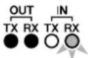 on flashon on flashon | Fan has Malfunctioned! The cooling fan has stopped operating. | Check that nothing is caught in the fan. If the problem cannot be easily resolved, contact your Yamaha dealer. | |
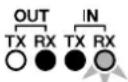 flashonon flashonon | Duplicate IP Address! A device with an IP address that is the same as the SB168-ES fixed IP address is connected to the NETWORK connector. | Change the IP address of the device connected to the NETWORK connector to an IP address other than 192.168.0.2. | |
 flashonflash flashonflash | Illegal DIP Switch Setting! The device is operating with the DIP switches set to initialization or some other special mode. | To resume normal operation turn the power OFF, set DIP switches 5–8 to their “up” positions, then turn the power ON again. | |
Information
The indicators will flash and/or light for 10 seconds.
| Indicators | AVS-ESMonitor Error Status | Details Solution | |
 | HA Remote Communication Error! (Rx Buffer Full) | Too much data has been received at the HA Remote input port. | If any of these errors occur frequently, a device malfunction may be the cause. Contact your Yamaha dealer. |
 | HA Remote Communication Error! (Overrun) | An inappropriate signal has been received at the HA Remote input port. | |
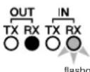 | HA Remote Communication Error! (Framing) | An inappropriate signal has been received at the HA Remote input port. | |
 | HA Remote Communication Error! (Tx Buffer Full) | Too much data has been transmitted via the HA Remote output port. |
General Specification
| Power Requirements | US/Canada: 120V 65W, 60HzKorea: 220V 65W, 60HzChina: 110V–240V 65W, 50/60HzJapan: 100V 65W, 50/60HzOther: 110V–240V 65W, 50/60Hz |
| Dimensions 480 x 350 x 132 mm (W x D x H) | |
| Net Weight 8 kg | |
| Temperature Range | Operation free-air : ± 0 °C to +40 °CStorage : -20 °C to +60 °C |
| AC Cable Length 250 cm | |
| Accessories Owner's Manual, AC Cable | |
Input/Output Characteristics
● Analog Input Characteristics
| Input Terminals | GAIN | Actual Load Impedance | For Use With Nominal | Input Level | Connector | |
| Nominal Max. | before clip | |||||
| INPUT 1–16 | -62 dB | 3 kΩ | 50–600 Ω Mics & 600 Ω Lines | -62 dBu (0.616 mV) | -42 dBu (6.16 mV) | XLR-3-31 type (Balanced)*1 |
| +10 dB | +10 dBu (2.45 V) | +30 dBu (24.5 V) | ||||
*1. XLR-3-31 type connectors are balanced. (1=GND, 2=HOT, 3=COLD)
* In these specifications, when dBu represents a specific voltage, 0 dBu is referenced to 0.775 Vrms.
* AD converters are 24-bit linear, 128-times oversampling.
● Analog Output Characteristics
| Output Terminals | Actual Source Impedance | For Use With Nominal | Max. Output Level Select SW | Output Level | Connector | |
| Nominal Max. | before clip | |||||
| OUTPUT 1–8 | 75 Ω | 600 Ω Lines | +24 dB (default) | +4 dBu (1.23 V) | +24 dBu (12.3 V) | XLR-3-32 type (Balanced)*1 |
| +18 dB | -2 dBu (616 mV) | +18 dBu (6.16 V) | ||||
*1. XLR-3-32 type connectors are balanced. (1=GND, 2=HOT, 3=COLD)
* In these specifications, when dBu represents a specific voltage, 0 dBu is referenced to 0.775 Vrms.
* D A converters are 24-bit, 128-times oversampling.
● Digital Input/Output Characteristics
| Terminal | Format | Data Length | Level | Audio | Connector | |
| EtherSound | IN | EtherSound | 24bit | 100 Base-TX | 8 ch Input/16 ch Output | RJ-45*1 |
| OUT | ||||||
*1. Use a RJ-45 connector compliant with Neutrik etherCON® CAT5.
* Use a CAT5e STP (Shielded Twisted Pair) cable compliant with EtherSound.
* Use electrically conductive tape to securely connect the metal part of the connector with the shielded part of the cable in order to prevent electromagnetic interference.
* An EtherSound certified cable is recommended. Maximum length available depends on each cable specification.
● Control I/O Characteristics
| Terminal | Format | Level | Connector |
| NETWORK IEE802.3 | 10 Base-T/100 Base-TX | RJ-45 | |
* A CAT5e STP (Shielded Twisted Pair) cable is recommended. Maximum length is 100 m.
Electrical Characteristics
Output impedance of single generator: 150Ω
Measured with another SB168-ES through EtherSound
● Frequency Response
Fs= 44.1 kHz or 48 kHz@20 Hz–20 kHz, reference to the nominal output level @ 1 kHz
| Input Output RL Conditions Min. Typ. | Max. Unit | ||||||
| INPUT 1–16 | OUTPUT 1–8 | 600 Ω | GAIN: +10dB | -1.5 | 0 | 0.5 | dB |
● Gain Error Fs= 44.1 kHz, 48 kHz@ 1 kHz
| Input | Output | RL | Conditions | Min. | Typ. | Max. | Unit |
| INPUT 1–16 | OUTPUT 1–8 | 600 Ω | Input level: -62 dBu, GAIN: -62dB → Output level +4.0 dBu (Typ.) | -2 | 0 2 | dB | |
| Input level: +10 dBu, GAIN: +10dB → Output level +4.0 dBu (Typ.) | -2 | 0 2 |
● Total Harmonic Distortion Fs= 44.1 kHz or 48 kHz
| Input | Output | RL | Conditions | Min. | Typ. | Max. | Unit |
| INPUT 1–16 | OUTPUT 1–8 | 600 Ω | +4 dBu@20 Hz–20 kHz, GAIN: -62dB | 0.1 | % | ||
| +4 dBu@20 Hz–20 kHz, GAIN: +10dB | 0.05 |
* Total Harmonic Distortion is measured with a 18 dB/octave filter @80 kHz.
● Hum & Noise
Fs= 44.1 kHz or 48 kHz, EIN= Equivalent Input Noise
| Input | Output | RL | Conditions | Min. | Typ. | Max. | Unit |
| INPUT 1–16 | OUTPUT 1–8 | 600 Ω | Rs=150Ω, GAIN: -62 dB | -128EIN | dBu | ||
| -62 | |||||||
| Rs=150Ω, GAIN: +10 dB | -84 | -80 |
* Hum & Noise are measured with a 6 dB/octave filter @12.7 kHz; equivalent to a 20 kHz filter with infinite dB/octave attenuation.
● Dynamic Range Fs= 44.1 kHz or 48 kHz
| Input | Output | RL | Conditions | Min. | Typ. | Max. | Unit |
| INPUT 1–16 | OUTPUT 1–8 | 600 Ω | GAIN: +10dB | 108 | dB |
* Dynamic Range is measured with a 6 dB/octave filter @12.7 kHz; equivalent to a 20 kHz filter with infinite dB/octave attenuation.
● Crosstalk @ 1 kHz Fs= 44.1 kHz or 48 kHz
| From/To | To/From | Conditions | Min. | Typ. | Max. | Unit |
| INPUT N | INPUT (N-1) or (N+1) | INPUT 1–16, adjacent inputs,GAIN: +10dB | -80 | dB | ||
| OUTPUT N | OUTPUT (N-1) or (N+1) | OUTPUT 1–8, input to output | -80 |
● Phantom Voltage
| Output | Conditions | Min. | Typ. | Max. | Unit | |
| INPUT 1–16 | hot & cold: No load | 46 | 48 | 50 | V |
● Sampling Frequency
| Parameter | Conditions | Min. | Typ. | Max. | Unit | |
| External Clock | Frequency Range | 43.00 | 49.20 | kHz | ||
| Internal Clock | Frequency | 48 | kHz | |||
| Accuracy | 50 | ppm | ||||
Dimensions

Unit: mm
Compatible Host List
| Compatible Host Maximum Usable Units Maximum Audio Channels HA Remote Connection | |||
| M7CL-48ES 3 48in / 24out EtherSound connector | |||
| M7CL-48 3 48in / 24out D-sub 9pin | |||
| M7CL-32 3 48in / 24out D-sub 9pin | |||
| LS9-32 2 32in / 16out via MY Card Slot | |||
| LS9-16 1 16in / 8out via MY Card Slot | |||
| DM1000 2 32in / 16out D-sub 9pin | |||
| DM2000 4 64in / 32out D-sub 9pin | |||
| PM5D/PM5D-RH | 4 64in / 32out D-sub 9pin | ||
| DME64N 4 64in / 32out D-sub 9pin | |||
| DME24N 1 16in / 8out | D-sub 9pin | ||
| DME8i-ES/8o-ES/4io-ES | 4 | 64in / 32out | Not supported |
| 02R96 | 4 64in / 32out | Not supported | |
| 01V96 | 1 16in / 8out | Not supported | |
* Refer to the Yamaha Pro Audio global website for the most recent information on compatible host controllers. http://www.yamahaproaudio.com/
MEMO
MEMO
EN

Information for Users on Collection and Disposal of Old Equipment
This symbol on the products, packaging, and/or accompanying documents means that used electrical and electronic products should not be mixed with general household waste.
For proper treatment, recovery and recycling of old products, please take them to applicable collection points, in accordance with your national legislation and the Directives 2002/96/EC.
By disposing of these products correctly, you will help to save valuable resources and prevent any potential negative effects on human health and the environment which could otherwise arise from inappropriate waste handling.
For more information about collection and recycling of old products, please contact your local municipality, your waste disposal service or the point of sale where you purchased the items.
[For business users in the European Union]
If you wish to discard electrical and electronic equipment, please contact your dealer or supplier for further information.
[Information on Disposal in other Countries outside the European Union]
This symbol is only valid in the European Union. If you wish to discard these items, please contact your local authorities or dealer and ask for the correct method of disposal.
DE
![YAMAHA SB168-ES - [Information on Disposal in other Countries outside the European Union] - 1](/content/2026/05/912888/images/1067c296343047fe730392a29201bf275d93e598de2a6972fcab3008f97b6fbe.jpg)
This product, when installed as indicated in the instructions contained in this manual, meets FCC requirements. Modifications not expressly approved by Yamaha may void your authority, granted by the FCC, to use the product.
2. IMPORTANT: When connecting this product to accessories and/or another product use only high quality shielded cables. Cable/s supplied with this product MUST be used. Follow all installation instructions. Failure to follow instructions could void your FCC authorization to use this product in the USA.
3. NOTE: This product has been tested and found to comply with the requirements listed in FCC Regulations, Part 15 for Class "B" digital devices. Compliance with these requirements provides a reasonable level of assurance that your use of this product in a residential environment will not result in harmful interference with other electronic devices. This equipment generates/uses radio frequencies and, if not installed and used according to the instructions found in the users manual, may cause interference harmful to the opera-
tion of other electronic devices. Compliance with FCC regulations does not guarantee that interference will not occur in all installations. If this product is found to be the source of interference, which can be determined by turning the unit "OFF" and "ON", please try to eliminate the problem by using one of the following measures:
Relocate either this product or the device that is being affected by the interference.
Utilize power outlets that are on different branch (circuit breaker or fuse) circuits or install AC line filter/s.
In the case of radio or TV interference, relocate/reorient the antenna. If the antenna lead-in is 300 ohm ribbon lead, change the lead-in to co-axial type cable.
If these corrective measures do not produce satisfactory results, please contact the local retailer authorized to distribute this type of product. If you can not locate the appropriate retailer, please contact Yamaha Corporation of America, Electronic Service Division, 6600 Orangethorpe Ave, Buena Park, CA90620
The above statements apply ONLY to those products distributed by Yamaha Corporation of America or its subsidiaries.
* This applies only to products distributed by YAMAHA CORPORATION OF AMERICA. (class B)
COMPLIANCE INFORMATION STATEMENT (DECLARATION OF CONFORMITY PROCEDURE)
Responsible Party : Yamaha Corporation of America
Address : 6600 Orangethorpe Ave., Buena Park, Calif. 90620
Telephone : 714-522-9011
Type of Equipment : STAGE BOX
Model Name : SB168-ES
This device complies with Part 15 of the FCC Rules.
Operation is subject to the following two conditions:
1) this device may not cause harmful interference, and
2) this device must accept any interference received including interference that may cause undesired operation.
See user manual instructions if interference to radio reception is suspected.
* This applies only to products distributed by YAMAHA CORPORATION OF AMERICA.
(FCC DoC)
IMPORTANT NOTICE FOR THE UNITED KINGDOM
Connecting the Plug and Cord
WARNING: THIS APPARATUS MUST BE EARTHED
IMPORTANT. The wires in this mains lead are coloured in accordance with the following code:
GREEN-AND-YELLOW : EARTH
BLUE : NEUTRAL
BROWN : LIVE
As the colours of the wires in the mains lead of this apparatus may not correspond with the coloured markings identifying the terminals in your plug proceed as follows:
The wire which is coloured GREEN-and-YELLOW must be connected to the terminal in the plug which is marked by the letter E or by the safety earth symbol ⏻ or colored GREEN or GREEN-and-YELLOW.
The wire which is coloured BLUE must be connected to the terminal which is marked with the letter N or coloured BLACK.
The wire which is coloured BROWN must be connected to the terminal which is marked with the letter L or coloured RED.
This product contains a battery that contains perchlorate material.
Perchlorate Material—special handling may apply,
See www.dtsc.ca.gov/hazardouswaste/perchlorate.
* This applies only to products distributed by (Perchlorate) YAMAHA CORPORATION OF AMERICA.
ADVARSEL!
For details of products, please contact your nearest Yamaha representative or the authorized distributor listed below.
Yamaha Canada Music Ltd.
135 Milner Avenue, Toronto, Ontario,
M1S 3R1, Canada
Tel: 416-298-1311
U.S.A.
Yamaha Corporation of America
6600 Orangethorpe Avenue, Buena Park, CA 90620,
U.S.A.
Tel: 714-522-9011
CENTRAL & SOUTH AMERICA
MEXICO
PANAMA AND OTHER LATIN
AMERICAN COUNTRIES/
CARIBBEAN COUNTRIES
Yamaha Music Latin America, S.A.
Torre Banco General, Piso No.7, Marbella,
Sherbourne Drive, Tilbrook, Milton Keynes,
MK7 8BL, U.K.
Tel: 01908-366700
GERMANY
Yamaha Music Europe GmbH
Siemensstraße 22-34, 25462 Rellingen, Germany
Tel: 04101-3030
Branch Switzerland in Zürich
Seefeldstrasse 94, 8008 Zürich, Switzerland
Tel: 044-387-8080
AUSTRIA/BULGARIA
Yamaha Music Europe GmbH Branch Austria
Schleiergasse 20, A-1100 Wien, Austria
Tel: 01-60203900
CZECH REPUBLIC/HUNGARY/
ROMANIA/SLOVAKIA/SLOVENIA
Yamaha Music Europe GmbH
Branch Austria (Central Eastern Europe Office)
Schleiergasse 20, A-1100 Wien, Austria
Tel: 01-60203900
POLAND/LITHUANIA/LATVIA/ESTONIA
Yamaha Music Europe GmbH
Branch Poland Office
Yamaha Music Europe GmbH, Branch Italy
Viale Italia 88, 20020 Lainate (Milano), Italy
Tel: 02-935-771
SPAIN/PORTUGAL
Yamaha Music Europe GmbH Ibérica, Sucursal
en España
Ctra. de la Coruna km. 17,200, 28231
Las Rozas (Madrid), Spain
147 Skiathou Street, 112-55 Athens, Greece
Tel: 01-228 2160
SWEDEN/FINLAND/ICELAND
Yamaha Music Europe GmbH Germany filial
Scandinavia
J. A. Wettergrensgata 1, Box 30053
S-400 43 Göteborg, Sweden
Tel: +46 31 89 34 00
DENMARK
Yamaha Music Europe GmbH, Tyskland – filial
Denmark
Generatorvej 6A, DK-2730 Herlev, Denmark
Tel: 44 92 49 00
NORWAY
Yamaha Music Europe GmbH Germany -
Norwegian Branch
Grini Næringspark 1, N-1361 ∅sterås, Norway
Tel: 67 16 78 00
RUSSIA
Yamaha Music (Russia) LLC.
Room 37, bld. 7, Kievskaya street, Moscow,
121059, Russia
Tel: 495 626 5005
OTHER EUROPEAN COUNTRIES
Yamaha Music Europe GmbH
Siemensstraße 22-34, 25462 Rellingen, Germany
Tel: +49-4101-3030
AFRICA
Yamaha Music Gulf FZE
Office JAFZA 16-512, P.O.Box 17328,
Jebel Ali - Dubai, UAE
Tel: +971-4-881-5868
MIDDLE EAST
TURKEY
Yamaha Music Europe GmbH
Office JAFZA 16-512, P.O.Box 17328,
Jebel Ali - Dubai, U.A.E
Tel: +971-4-881-5868
ASIA
THE PEOPLE'S REPUBLIC OF CHINA
Yamaha Music & Electronics (China) Co., Ltd.
2F, Yunhedasha, 1818 Xinzha-lu, Jingan-qu,
Shanghai, China
Tel: 021-6247-2211
INDIA
Yamaha Music India Pvt. Ltd.
Spazedge building, Ground Floor, Tower A, Sector
47, Gurgaon- Sohna Road, Gurgaon, Haryana, India
Tel: 0124-485-3300
INDONESIA
PT. Yamaha Musik Indonesia (Distributor)
Yamaha Music Center Bldg. Jalan Jend. Gatot
Subroto Kav. 4, Jakarta 12930, Indonesia
Tel: 021-520-2577
KOREA
Yamaha Music Korea Ltd.
8F, 9F, Dongsung Bldg. 158-9 Samsung-Dong,
Kangnam-Gu, Seoul, Korea
Tel: 02-3467-3300
MALAYSIA
Yamaha Music (Malaysia) Sdn., Bhd.
No.8, Jalan Perbandaran, Kelana Jaya, 47301
Petaling Jaya, Selangor, Malaysia
Tel: 03-78030900
SINGAPORE
Yamaha Music (Asia) Private Limited
Block 202 Hougang Street 21, #02-00,
Singapore 530202, Singapore
Tel: 65-6747-4374
TAIWAN
Yamaha Music & Electronics Taiwan Co., Ltd.
3F, No.6, Section 2 Nan-Jing East Road, Taipei,
Taiwan R.O.C.
Tel: 02-2511-8688
THAILAND
Siam Music Yamaha Co., Ltd.
3, 4, 15 and 16th floor, Siam Motors Building,
891/1 Rama 1 Road, Wangmai,
Pathumwan, Bangkok 10330, Thailand
Tel: 02-215-2622
VIETNAM
Yamaha Music Vietnam Company Limited
15th Floor, Nam A Bank Tower, 201-203 Cach
Mang Thang Tam St., Ward 4, Dist.3,
Ho Chi Minh City, Vietnam
Tel: +84-8-3818-1122
OTHER ASIAN COUNTRIES
Yamaha Corporation
Sales & Marketing Division
Nakazawa-cho 10-1, Naka-ku, Hamamatsu,
Japan 430-8650
Tel: +81-53-460-2312
OCEANIA
AUSTRALIA
Yamaha Music Australia Pty. Ltd.
Level 1, 99 Queensbridge Street, Southbank,
Victoria 3006, Australia
Tel: 3-9693-5111
COUNTRIES AND TRUST
TERRITORIES IN PACIFIC OCEAN
Yamaha Corporation
Sales & Marketing Division
Nakazawa-cho 10-1, Naka-ku, Hamamatsu,
Japan 430-8650
Tel: +81-53-460-2312

YAMAHA
Yamaha Pro Audio global web site: http://www.yamahaproaudio.com/
Yamaha Manual Library http://www.yamaha.co.jp/manual/
C.S.G., PA Development Division © 2008-2013 Yamaha Corporation
311POTO-E0 Printed in Japan
WP93760
- Explanation of Graphical Symbols
- IMPORTANT SAFETY INSTRUCTIONS
- WARNING
- PRECAUTIONS
- PLEASE READ CAREFULLY BEFORE PROCEEDING
- Power supply/Power cord
- Do not open
- Water warning
- If you notice any abnormality
- CAUTION
- Location
- Connections
- Handling caution Backup battery
- European models
- Contents
- Foreword....6
- About EtherSound 8
- Controls and Functions....10
- System Examples ......12
- Setup....13
- Head Amp Control ....18
- Troubleshooting....20
- References....167
- Included Accessories
- Foreword
- SB168-ES Features
- ■ Long-distance EtherSound Network Capability
- ■ Remotely Controllable Internal Head Amplifiers
- ■ Up to Four SB168-ES Units\* Can Be Used for Expanded I/O
- Firmware Updates
- Connecting the AC Power Cable
- Powering ON or OFF
- Precautions for Rack Mounting
- Recessed installation
- Resetting the Unit to Initial Factory Condition (Initialization)
- EtherSound is ...
- Daisy Chain and Ring Networks
- Front Panel
- ① INPUT 1–16 Connectors
- NOTE
- ② +48V Indicators
- ③ SIG Indicators
- ④ PEAK Indicators
- ⑤ EtherSound [IN]/[OUT] Connectors
- ⑥ IN/OUT [TX]/[RX] Indicators
- ⑦ DIP Switches 1–8
- ⑧ [+48V MASTER] Switch
- Power Indicator
- ⑩ [POWER] Switch
- ⑪ OUTPUT 1–8 Connectors
- ① Earth Screw
- ② [AC IN] Socket
- ③ NETWORK Connector
- ④ [FAN] Switch
- Daisy Chain Connection
- Daisy Chain Characteristics
- Ring Connection
- Ring Connection Characteristics
- About the AVS-ESMonitor Software
- Initial Setup Using the Quick Setup Function
- Preparation
- Setup Procedure
- Individual Parameter Settings (Control Page)
- Synchro Status
- Error Status
- Lock Routing
- Input Signal Peak/Output Signal Peak
- Serial Communication Mode
- Head Amp Remote Option
- Tools
- Emergency Clock
- Settings from DIP Switch 5-8 (for M7CL-48ES)
- Setup Error Messages
- Control from a Digital Mixing Console
- Control From the AVS-ESMonitor Application
- Click the Head Amp Tab.
- Messages
- Error Messages
- Warning Messages
- Information
- Input/Output Characteristics
- ● Analog Input Characteristics
- Electrical Characteristics
- MEMO
- Information for Users on Collection and Disposal of Old Equipment
- [For business users in the European Union]
- [Information on Disposal in other Countries outside the European Union]
- COMPLIANCE INFORMATION STATEMENT (DECLARATION OF CONFORMITY PROCEDURE)
- IMPORTANT NOTICE FOR THE UNITED KINGDOM
- Connecting the Plug and Cord
- ADVARSEL!
- U.S.A.
- CENTRAL & SOUTH AMERICA
- MEXICO
- PANAMA AND OTHER LATIN
- AMERICAN COUNTRIES/
- CARIBBEAN COUNTRIES
- GERMANY
- AUSTRIA/BULGARIA
- CZECH REPUBLIC/HUNGARY/
- ROMANIA/SLOVAKIA/SLOVENIA
- POLAND/LITHUANIA/LATVIA/ESTONIA
- SPAIN/PORTUGAL
- SWEDEN/FINLAND/ICELAND
- DENMARK
- NORWAY
- RUSSIA
- OTHER EUROPEAN COUNTRIES
- AFRICA
- MIDDLE EAST
- TURKEY
- ASIA
- THE PEOPLE'S REPUBLIC OF CHINA
- INDIA
- INDONESIA
- KOREA
- MALAYSIA
- SINGAPORE
- TAIWAN
- THAILAND
- VIETNAM
- OTHER ASIAN COUNTRIES
- OCEANIA
- AUSTRALIA
- COUNTRIES AND TRUST
- TERRITORIES IN PACIFIC OCEAN
- YAMAHA
Brand : YAMAHA
Model : SB168-ES
Category : Professional audio equipment