Stealthbox SB-VW-JETNCS/10W1v3 - Subwoofer JL Audio - Free user manual and instructions
Find the device manual for free Stealthbox SB-VW-JETNCS/10W1v3 JL Audio in PDF.

User questions about Stealthbox SB-VW-JETNCS/10W1v3 JL Audio
0 question about this device. Answer the ones you know or ask your own.
Ask a new question about this device
Download the instructions for your Subwoofer in PDF format for free! Find your manual Stealthbox SB-VW-JETNCS/10W1v3 - JL Audio and take your electronic device back in hand. On this page are published all the documents necessary for the use of your device. Stealthbox SB-VW-JETNCS/10W1v3 by JL Audio.
USER MANUAL Stealthbox SB-VW-JETNCS/10W1v3 JL Audio
INSTALLATION GUIDE for the
SB-VW-JETNCS/10W1v3
SKU# 94533
2011 & Up Volkswagen Jetta
natural_image
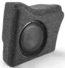
Close-up of a gray foam speaker with a circular lens (no text or symbols visible)Thank you for choosing a JL Audio Stealthbox® for your automotive sound system.
With proper installation, your new vehicle-specific enclosed subwoofer system
will deliver years of listening pleasure.
We strongly recommend that you have your new Stealthbox ^® installed by your authorized JL Audio dealer. The installation professionals employed by your dealer have the necessary tools and experience to disassemble and reassemble your vehicle properly. Also, keep in mind that your warranty coverage extends to 2 years if your system is installed or approved by your authorized JL Audio dealer. If you prefer to perform your own installation, please read this installation guide completely before beginning the process.
JL AUDIO.
Ahead of the Curve
! IMPORTANT
If you choose to perform the installation yourself, it is absolutely vital that the Stealthbox* be properly mounted to the vehicle according to these instructions. Failure to mount the enclosure properly presents two problems:
1) The sub-bass performance will suffer due to the movement of the enclosure caused by the force exerted by the woofer(s).
2) A loose enclosure presents a serious safety hazard in the event of a collision or sudden deceleration.
INSTALLATION DIFFICULTY:

ESTIMATED TIME: 1.5 HOUR
natural_image
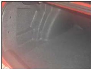
Close-up of a transparent container with liquid, showing surface texture and measurement markings (no readable text or symbols)STEP 1
Empty out the trunk of the car so that you have a clean area to work in.
natural_image
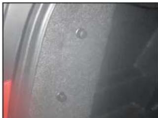
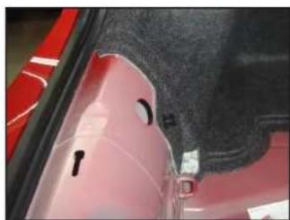
Close-up of a car's side panel showing two circular indentations and a red accent (no text or symbols visible)STEP 2
Remove the two clips holding the rear of the trunk liner in place.
natural_image
Close-up of a car's wheel and suspension system with red components (no visible text or symbols)STEP 3
Remove the clip holding the trunk liner to the rear deck
natural_image
Close-up of a hand using a tool to clean or inspect a red car wheel rim (no visible text or symbols)STEP 4
Remove the trunk floor panel.
natural_image
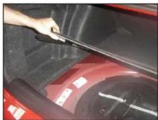
Close-up of a red car hood with a hand holding a black plastic clip (no visible text or symbols)STEP 5
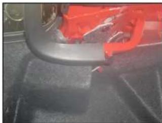
Carefully unclip and remove the trunk sill panel.
natural_image
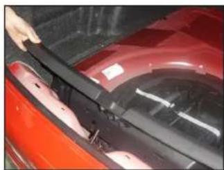
Close-up of a car's side panel showing red and black components, no visible text or symbolsSTEP 6
Remove the clip that holds the trunk liner to the back of the trunk.
natural_image
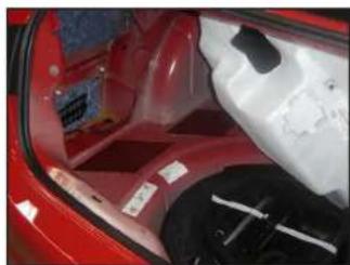
Interior view of a red car showing rear seats, dashboard, and gear (no visible text or symbols)STEP 7
Pull the trunk liner away from the side of the trunk as shown.
natural_image
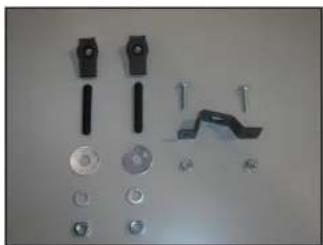
Collection of mechanical components and fasteners on a plain surface (no text or symbols visible)STEP 8
Pictured is the hardware included with this Stealthbox.
natural_image
Close-up of a medical or laboratory setup with a blue grid overlay and metal components (no visible text or symbols)STEP 9
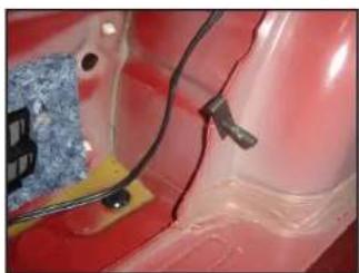
Slice a U-Nut over the factory hole in the wheel well as shown.
natural_image
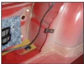
Close-up of a medical or laboratory setup with a blue plastic component and wiring, no visible text or symbolsSTEP 10
Thread a 3/8 - 16 x 2-1/4" Set Screw into the U-Nut as shown.
natural_image
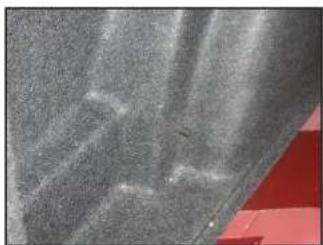
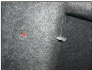
Close-up of a textured surface with diagonal striations and small dark spots, possibly fabric or material (no text or symbols visible)STEP 11
Push the trunk liner back in place to mark the location of the 3/8 - 16 x 2-14" Set Screw. Cut an "X" into the trunk liner to allow the screw to pass through as shown.
natural_image
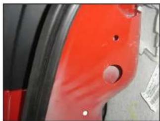
Close-up of a red car wheel with mounting holes and a small white object, no visible text or symbols.STEP 12
Locate the two holes at the rear of the trunk near the taillight.
flowchart
graph TD
    A["Start"] --> B{Decision}
    B -->|Yes| C["INDIVATED SERVICE"]
    B -->|No| D["MOUNTED GUIDE"]
    C --> E["End"]
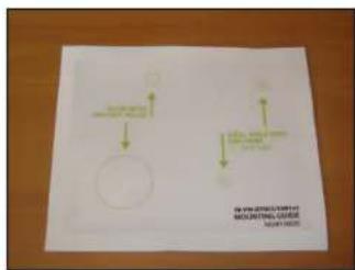
STEP 13
Align the Template Sticker over the two holes, and affix the sticker.
natural_image
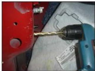
Close-up of a red metal tool with a drill bit being inserted, next to a blue-handled tool (no visible text or symbols)STEP 14
Using a 1/4" drill bit, drill the two mounting holes as indicated on the Template Sticker.
Before drilling, always make sure that you are not going to be drilling into any gas lines, brake lines, tires, transmission lines, electrical wiring, exhaust systems or anything else that might cause a reduction in your weekly pay.
Always wear eye protection when drilling!
natural_image
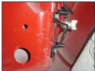
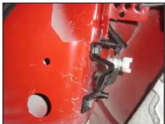
Close-up of a red metal bracket with bolts and a small white connector (no visible text or symbols)STEP 15
Secure the Bracket with a pair of 1/4 - 20 x 1" Bolts through the holes drilled in the previous step.
natural_image
Close-up of a hand using a green tool to adjust or install a red automotive component (no visible text or symbols)STEP 16
Thread a 1/4 - 20 KEPS Nut onto the back of the upper 1/4 - 20 x 1" Bolt and firmly tighten. We recommend stuffing a shop rag down the cavity to prevent losing the nut if dropped.
natural_image
Close-up of hands installing or adjusting a red car seat cover with a green tool (no visible text or symbols)STEP 17
Thread a 1/4 20 KEPS Nut onto the back of the lower 1/4 20 x 1" Bolt and firmly tighten. Remove the shop rag from the cavity.
natural_image
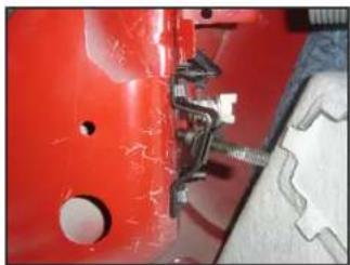
Close-up of a red mechanical component with visible cracks and holes (no text or symbols)STEP 18
Slice a U-Nut over the hole in the Bracket as shown.
natural_image
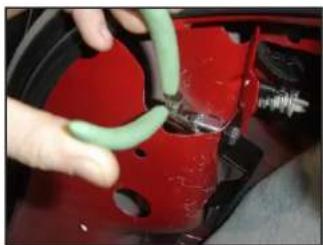
Close-up of a red mechanical component with a metallic tool inserted, showing no visible text or symbols.STEP 19
Thread a 3/8 - 16 x 2-1/4" Set Screw into the U-Nut as shown.
natural_image
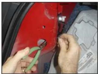
Close-up of a mechanical component with a red dot and a white lever, set against a textured gray background (no visible text or symbols)STEP 20
Push the trunk liner back in place to mark the location of the 3/8 - 16 x 2-1/4" Set Screw. Cut an "X" into the trunk liner to allow the screw to pass through as shown.
natural_image
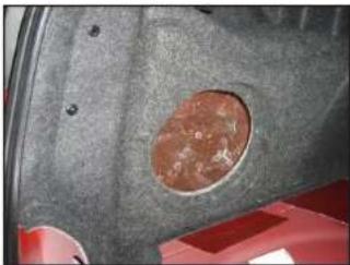
Close-up of a car wheel rim with a circular hole and textured surface (no text or symbols visible)STEP 21
Reinstall the clips that hold the trunk liner in place. Remove the subwoofer from the Stealthbox ^® . Attach speaker cable to the Stealthbox ^® , and place the enclosure into position, allowing both 3/8 - 16 x 2 1/4" Set Screws to pass through the holes in the enclosure.
natural_image
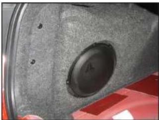
Close-up of a speaker grille mounted on a vehicle wheel, with red and black components visible (no text or symbols)STEP 22
Thread a 3/8" Fender Washer, a 3/8" Split Lock Washer, and a 3/8" Hex Nut over each of the 3/8 - 16 x 2-1/4" Set Screws, and firmly tighten. Reinstall the woofer, Reinstall the trunk sill panel and floor panel.
natural_image
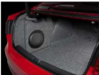
Close-up of a car trunk showing a gray plastic cover and a circular vent (no text or symbols visible)CONGRATULATIONS!
You have completed the installation for this model!
Enjoy your new Stealthbox*!
Please refer to the Power Recommendation section for an amplifier recommendation and basic set-up help.
INCLUDED HARDWARE
| (1) Template Sucker | (2) 3/8 - 16 x 2-1/4" Set Screw | (2) 3/8" Hex Nut |
| (1) Bracket | (2) 3/8" Fender Washer | (2) 1/4 - 20 x 1" Bolt |
| (2) U Nut | (2) 3/8" Split Lock Washer | (2) 1/4 - 20 KEPS Nut |
SPECIFICATIONS
Enclosure Type: Acoustic Suspension (sealed)
Driver Type: 104/1v3-2
Nominal Impedance: 2 ohm
Continuous Power Handling: 300 watt
POWER RECOMMENDATION
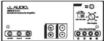
JL Audio recommends high quality amplifiers such as the JL Audio XD300/1v2. The diagram below shows the recommended crossover settings for the XD300/1v2. If another amplifier is being used, please reference this illustration and use similar settings on that amplifier.
text_image
JL AUDIO. SOLUTION Audio sub-Blocker Amplifier Control buttons Control buttons Control buttons Control buttons Control buttons Control buttons Control buttons Control buttons Control buttons Control buttons Control buttons Control buttons Control buttons Control buttons Control buttons Control buttons Control buttons Control buttons Control buttons Control buttons Control buttons Control buttons Control buttons Control buttons Control buttons Control buttons Control buttons Control buttons Control buttons Control buttons Control buttons Control buttons Control buttons Control buttonsAll JL Audio amplifiers are very versatile audio components. Please consult the owner's manual for even more detailed information about installing and tuning your amplifier.
CONNECTIONS
Using quality power, signal and speaker wire is essential in ensuring the performance of your Stealthbox ^® . JL Audio recommends using a 4 AWG power kit such as the XD-PCS8-1B for your Stealthbox ^® amplifier. Other kits are available should you be using more than one amplifier. Signal wire such as the JL Audio Premium Audio Interconnect Cables should be used that will provide signal for both channels of the amplifier. JL Audio recommends using 12AWG speaker wire for subwoofers such as our XC-BCS12-25.
MID/HIGH FREQUENCY DRIVER FITMENT
A variety of JL Audio coaxial and component systems will fit in the factory speaker locations of you vehicle.
Front Speaker Size / Location: 6-1/2"- Front Doors
Fits JL Audio Models: TR650-CXi, TR650-CSI, C2-650x, C2-650, C3-650, C5-650x, C5-650, & ZR650-CSI
Rear Speaker Size / Location: 6-1/2"- Rear Door
Fits JL Audio Models: TR650-CXi, TR650-CSi, C2-650x, C2-650, C3-650, C5-650x, C5-650, & ZR650-CSi
JL AUDIO®
Ahead of the Curve
| (954) 443-1100 | www.jlaudio.com |
| If specifications are subject to changing conditions (see "A. Kafila" and "B. Kafila" and "Saulkina" and the Laudia logo, registered characteristics of A. Kafila, Inc. "Alfredi" or the "Cura" and to respect to a standard logo as a trademark of A. Kafila, Inc. JLA 56721132 00.20.2016 + (Print: 1954, n. 2016), Kafila, Inc. Note more detailed information please call us and is at www.jlaudio.com. | AMERA CHERI OZEN 2016 |
10369 NORTH COMMERCE PARKWAY · MIRAMAR, FLORIDA · 11025 · USA