Cybex SC 840DP - Switch Avocent - Free user manual and instructions
Find the device manual for free Cybex SC 840DP Avocent in PDF.

User questions about Cybex SC 840DP Avocent
0 question about this device. Answer the ones you know or ask your own.
Ask a new question about this device
Download the instructions for your Switch in PDF format for free! Find your manual Cybex SC 840DP - Avocent and take your electronic device back in hand. On this page are published all the documents necessary for the use of your device. Cybex SC 840DP by Avocent.
USER MANUAL Cybex SC 840DP Avocent
Cybex™ SC Switching System
Installer/User Guide
The information contained in this document is subject to change without notice and may not be suitable for all applications. While every precaution has been taken to ensure the accuracy and completeness of this document, Vertiv assumes no responsibility and disclaims all liability for damages resulting from use of this information or for any errors or omissions. Refer to other local practices or building codes as applicable for the correct methods, tools, and materials to be used in performing procedures not specifically described in this document.
The products covered by this instruction manual are manufactured and/or sold by Vertiv. This document is the property of Vertiv and contains confidential and proprietary information owned by Vertiv. Any copying, use or disclosure of it without the written permission of Vertiv is strictly prohibited.
Names of companies and products are trademarks or registered trademarks of the respective companies. Any questions regarding usage of trademark names should be directed to the original manufacturer.
Technical Support Site
If you encounter any installation or operational issues with your product, check the pertinent section of this manual to see if the issue can be resolved by following outlined procedures. Visit https://www.VertivCo.com/en-us/support/ for additional assistance.
TABLE OF CONTENTS
1 Product Overview 1
1.1 Features and Benefits 1
2 Basic Operation 3
2.0.1 Factory reset 3
2.1 Switch Overview 3
2.1.1 Switching between computers 9
2.1.2 Dedicated Peripheral Port (DPP) 10
2.1.3 KM multi-monitor support 10
2.2 Keyboard and Mouse Settings.... 12
2.2.1 Keyboard settings 12
2.2.2 Mouse settings.... 13
2.2.3 Filtered USB port (fUSB) 13
2.2.4 Interchangeable KVM to KM functionality.... 13
2.3 Keyboard Shortcuts 13
2.4 KM Configuration.... 15
2.4.1 Creating a KM configuration_file 15
2.4.2 Loading a KM configuration_file 21
3 Troubleshooting 23
3.1 General 23
3.2 KM Configuration File 23
3.3 Video 25
3.4 Keyboard 25
3.5 Mouse.... 26
3.6 DPP 26
4 Appendices 27
1 PRODUCT OVERVIEW
[[[Undefined variable Variables.]]] SC switches are field-proven, secure, KVM and KM switching solu with special support for government agencies. This switching system allows users to switch safely between computers operating at different classification levels from a single set of peripherals, provide continuous access to critical data. With multiple security features, the secure design prevents the transfer of data between the connected computers, ensuring data security is not compromised.

WARNING! This product is equipped with active intrusion protection and tamper-evident se. Tampering with the switch or breaking/removing the seals will permanently disable it and the warranty. If the enclosure appears to have been tampered with or if all the port I continuously, please contact Technical Support.
The appliances covered in this manual include:
KM Models:
• Cybex™ SC KM 120 Secure 2-Port KM Switch
• Cybex™ SC KM 140/145 Secure 4-Port KM Switches
KVM Models:
• Cybex™ SC 820D/920D Secure 2-Port DisplayPort and HDMI KVM Switches
• Cybex™ SC 820H/920H Secure 2-Port HDMI KVM Switches
- Cybex™ SC 820DP/920DP Secure 2-Port DisplayPort KVM Switches
• Cybex™ SC 840/845/940/945 Secure 4-Port DVI-I KVM Switches
• Cybex™ SC 840D/845D/940D/945D Secure 4-Port DisplayPort and HDMI KVM Switches
• Cybex™ SC 840H/845H/940H/945H Secure 4-Port HDMI KVM Switches
• Cybex™ SC 840DP/845DP/940DP/945DP Secure 4-port DisplayPort KVM Switches
- Cybex™ SC 920XD Secure 2-Port Mixed HDMI, DisplayPort and DVI-I KVM Dual Head KVI Switch
- Cybex™ SC 945XD Secure 4-Port Mixed HDMI, DisplayPort and DVI-I KVM Dual Head KVI Switch
• Cybex™ SC 840DP/845DP/940DP/945DP Secure 4-port DisplayPort KVM Switches
• Cybex™ SC 885DP/985DP Secure 8-port DisplayPort KVM Switches
1.1 Features and Benefits
The SC switching system offers the following options, depending on the model:
• Support for HDMI, DVI-I, VGA and/or DisplayPort video
- Support for Common Access Card (CAC), USB biometric device and USB authentication tok
• Certification to Evaluation Assurance Level (EAL) 4+
• Support for USB and PS/2 keyboard and mouse
NOTE: Supports most keyboards and mice. For more information, contact Technical Support.
The SC switching system is also designed to provide additional layers of security, preventing infinite data leaks between computers and providing additional USB port protection.
Table 1.1 Security and Protection Features
| FEATURE DESCRIPTION | |
| Complete network segmentation | Data flow is controlled and insulated from peripheral devices using optical data diodes. EDID emulators and internal firewalls protect shared displays and prevent external memory leaks. |
| Protection from shared resources | The switches are designed to securely operate, even when peripheral devices are vulnerable to signaling attacks. They do not allow computer access to any shared resource and do not share controllable power sources. |
| Non-reprogrammable firmware | Custom firmware is not reprogrammable preventing the ability to remotely attack switch controllers. |
| Audio protection | Microphone switching is not supported to prevent data leaks through audio ports. |
| CONSOLE USB port protection | CONSOLE USB ports protect from the use of unsafe USB storage devices. Unqualified devices are rejected when connect through the switch even though keyboard and mouse data is passed through. |
2 BASIC OPERATION
Although installation of your SC switching system is complete, ensure you have one of the followi compatible operating systems:
- Microsoft® Windows®
- Red Hat®, Ubuntu® or any other Linux® platform
• Mac OS® X version 10.3 or higher
The switches are compatible with stereo headphones and amplified stereo speakers.
NOTE: Do not connect a microphone device to the switch's audio output port. Opt to use the devices that do not include microphone capabilities.
Wireless devices and non-standard keyboards with integrated USB hubs and other USB-integrated devices are not fully supported for security reasons.
2.0.1 Factory reset
A factory reset clears the device settings and restores the device to its original configuration.
To factory reset:
Type Ctrl + Ctrl + F11
2.1 Switch Overview
The following figures and tables show the controls and connectors on the front panel and connected the back of the switching systems covered in this manual.
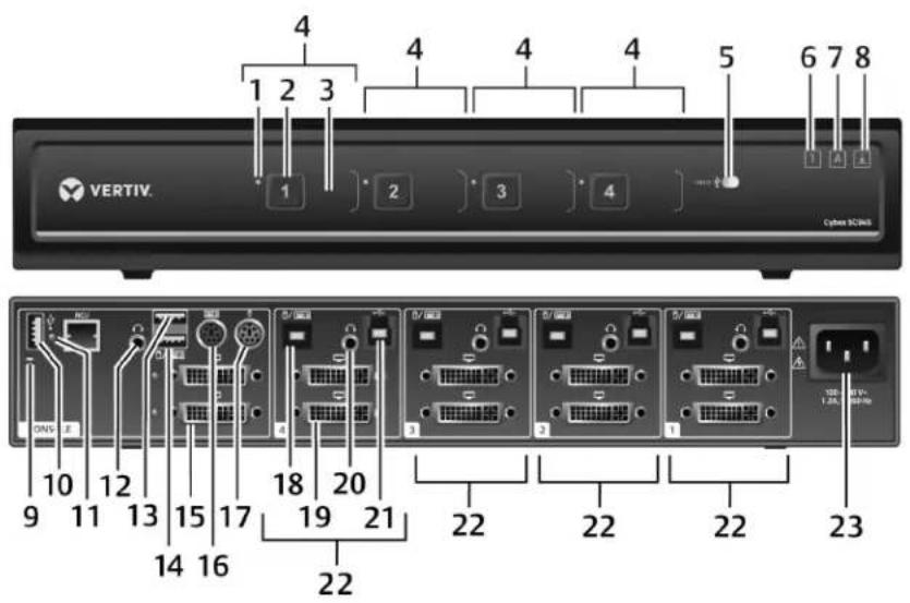
Figure 2.1 KVM Model (SC 945 Switch Shown)
text_image
4 1 2 3 4 4 4 5 6 7 8 VERTIV. Cybera SC2/NS 1 2 3 4 10 12 15 17 18 20 19 21 22 22 22 23 DNS E 9 11 13 15 17 14 16 22Table 2.1 KVM SC 945 Switch Description
| ITEM DESCRIPTION ITEM DESCRIPTION | |||
| 1 | LED channel indicator 13 | CONSOLE high-speed USB Type-A port | |
| 2 | Channel selector 14 | CONSOLE full-speed USB Type-A port | |
| 3 | Channel label | 15 | CONSOLE female video port (varies with model: DVI-I, HDMI or DisplayPort) |
| 4 | Channel configuration | 16 | Keyboard PS/2 mini-DIN 6-pin female port |
| 5 | Dedicated Peripheral Port (DPP) freeze button and LED | 17 | Mouse PS/2 mini-DIN 6-pin female port |
| 6 | Num lock indicator* | 18 | Keyboard and mouse USB Type-B port |
| 7 | Caps lock indicator* | 19 | Varies with model (DVI-I, HDMI or DisplayPort) |
| 8 | Scroll lock indicator* | 20 | Audio jack (3.5 mm stereo) |
| 9 | CONSOLE system reset | 21 | DPP USB Type-B port (CAC support only available on some models) |
| 10 | CONSOLE DPP USB Type-A port (CAC support: only available on some models) | 22 | Channel configuration |
| 11 | DPP LED indicator: | 23 | AC input (100-200 VAC) |
| Green: Functioning | |||
| Flashing green: Rejected device (not authorized) | |||
| None: Device not operating, non-standard USB device or device only operating in USB 3 mode | |||
| 12 | CONSOLE audio jack (3.5 mm stereo) | ||
* When these LED indicators are lit, they reflect the status of the keyboard functions on the active channel.
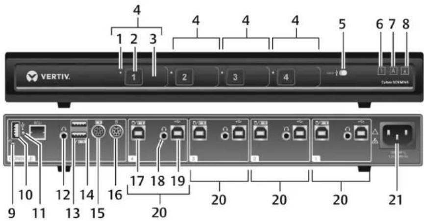
Figure 2.2 KM Model (SC KM145 Switch Shown)
text_image
4 1 2 3 4 4 4 5 6 7 8 VERTIV. Cyber SDRAM 9 10 11 12 13 14 15 16 17 18 19 20 20 20 20 21Table 2.2 KM SC KM145 Switch Description
| ITEM DESCRIPTION ITEM DESCRIPTION | |||
| 1 | LED channel indicator 12 | CONSOLE audio jack (3.5 mm stereo) | |
| 2 | Channel selector 13 | CONSOLE keyboard and mouse full-speed USB Type-A ports | |
| 3 | Channel label | 14 | CONSOLE keyboard and mouse high-speed USB Type-A ports |
| 4 | Channel configuration | 15 | Keyboard PS/2 mini-DIN 6-pin female port |
| 5 | Dedicated Peripheral Port (DPP) freeze button and LED | 16 | Mouse PS/2 mini-DIN 6-pin female port |
| 6 | Num lock indicator* | 17 | Keyboard and mouse USB Type-B port |
| 7 | Caps lock indicator* | 18 | Audio jack (3.5 mm stereo) |
| 8 | Scroll lock indicator* | 19 | DPP USB Type-B port (CAC support: only available on some models) |
| 9 | CONSOLE system reset | 20 | Channel configuration |
| 10 | CONSOLE DPP USB Type-A port (CAC support only available on some models) | 21 | AC input (100-200 VAC) |
| 11 | DPP LED indicator:Green: FunctioningFlashing green: Rejected device (not authorized)None: Device not operating, non-standard USB device or device only operating in USB 3 mode | ||
* When these LED indicators are lit, they reflect the status of the keyboard functions on the active channel.
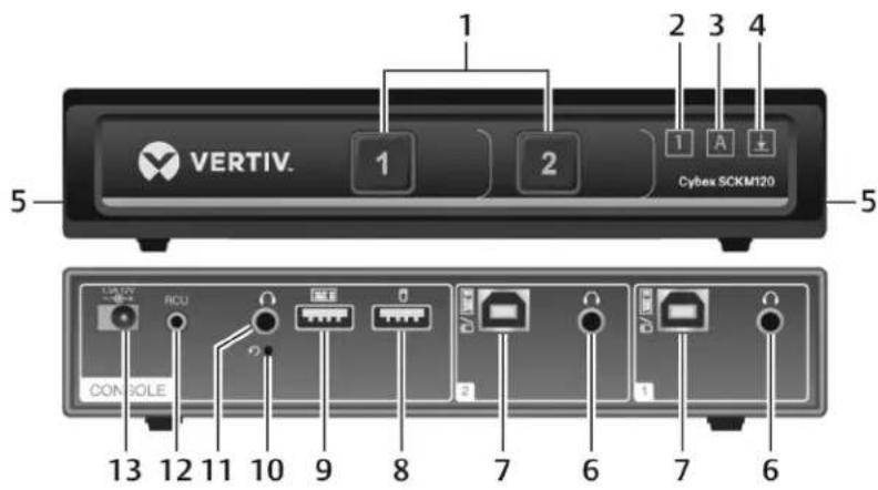
Figure 2.3 KM Model (SC KM120 Switch Shown)
text_image
VERTIV. 1 2 1 3 4 Cybex SCKM120 5 5 13 12 11 10 9 8 7 6 7 6 CONSOLETable 2.3 KM SC KM120 Switch Description
| ITEM DESCRIPTION ITEM DESCRIPTION | |||
| 1 | LED channel select button 8 | CONSOLE mouse USB Type-A port | |
| 2 | Num lock indicator* 9 | CONSOLE keyboard USB Type-A port | |
| 3 | Caps lock indicator* 10 | CONSOLE Restore to factory default button | |
| 4 | Scroll lock indicator* | 11 | CONSOLE audio jack (3.5 mm stereo) |
| 5 | Holographic tamper-evident labels | 12 | Remote Control Unit (RCU) portNOTE: The RCU port on the back panel is currently inoperable and is reserved for future use. |
| 6 | Audio jack (3.5 mm stereo) | 13 | DC power supply |
| 7 | Keyboard and mouse USB Type-B port | ||
| * When these LED indicators are lit, they reflect the status of the keyboard functions on the active channel. | |||
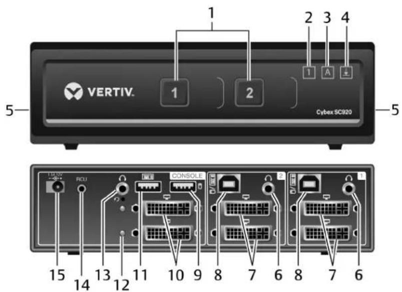
The SC 820 models are single-head devices. They have identical ports, except for the number of ports on the device. The SC 920 models (as shown in the following figure) are dual-head devices. The SC 920D and SC 920H models are identical except for the DP and HDMI video ports, respectively.
Figure 2.4 SC Model (SC920 KVM Switch Shown)
text_image
VERTIV. Cybex SC920 1 2 3 4 5 1 2 1 A ± 15 14 13 12 11 10 9 8 7 6 8 7 6Table 2.4 SC 920 KVM Switch Description
| ITEM DESCRIPTION ITEM DESCRIPTION | |||
| 1 | LED channel select button 9 | CONSOLE mouse USB Type-A port | |
| 2 | Num lock indicator 10 | CONSOLE DisplayPort video input port | |
| 3 | Caps lock indicator | 11 | CONSOLE keyboard USB Type-A port |
| 4 | Scroll lock indicator | 12 | Status LED |
| 5 | Holographic tamper-evident labels | 13 | CONSOLE audio input jack (3.5 mm stereo) |
| 6 | Audio jack (3.5 mm stereo) | 14 | Remote Control Unit (RCU) portNOTE: The RCU port on the back panel is currently inoperable and is reserved for future use. |
| 7 | DisplayPort video port | 15 | DC Power Supply |
| 8 | Keyboard and mouse USB Type-B port | ||
* When these LED indicators are lit, they reflect the status of the keyboard functions on the active channel.
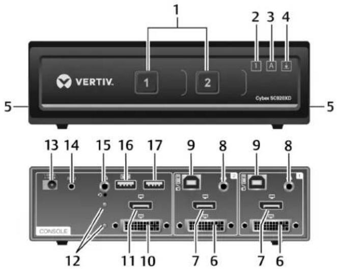
Figure 2.5 KVM Model (SC 920XP Switch Shown)
text_image
VERTIV. 1 2 3 4 Cyber SC920XD 5 13 14 15 16 17 9 8 9 8 CONSOLE 12 11 10 7 6 7 6Table 2.5 SC 920XP Switch Description
| ITEM DESCRIPTION ITEM DESCRIPTION | |||
| 1 | LED channel select button 10 | CONSOLE HDMI video input port | |
| 2 | Num lock LED 11 | CONSOLE DVI-I video input port | |
| 3 | Caps lock LED | 12 | Status LEDs |
| 4 | Scroll lock LED | 13 | DC power supply |
| 5 | Holographic tamper evident labels | 14 | Remote Control Unit (RCU) port |
| 6 | DVI-I video port | 15 | CONSOLE audio input jack (3.5 mm stereo) |
| 7 | HDMI video port | 16 | CONSOLE keyboard USB Type-A port |
| 8 | Audio jack (3.5 mm stereo) | 17 | CONSOLE mouse USB Type-A port |
| 9 | USB Type-B port for keyboard and mouse | ||
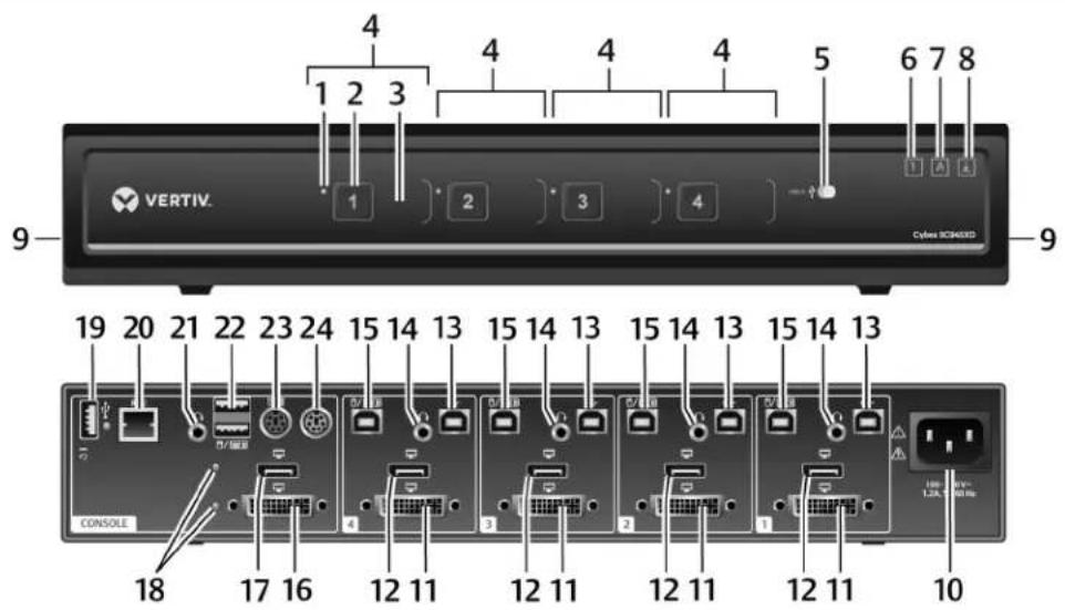
Figure 2.6 KVM Model (SC 945XP Switch Shown)
text_image
4 1 2 3 4 4 4 4 5 6 7 8 9 VERTIV. Cyleres SICR3XD 19 20 21 22 23 24 15 14 13 15 14 13 15 14 13 15 14 13 CONSOLE 18 17 16 12 11 12 11 12 11 12 11 12 11 10 1.3A, 1.0B HzTable 2.6 SC 945XD Switch Description
| ITEM DESCRIPTION ITEM DESCRIPTION | |||
| 1 | LED channel indicator 13 USB Type-B port for computer | ||
| 2 | Channel selector 14 Audio jack (3.5 mm stereo) | ||
| 3 | Channel label | 15 USB Type-B port for keyboard and mouse | |
| 4 | Channel configuration | 16 | CONSOLE DVI-I video input port |
| 5 | Dedicated Peripheral Port (DPP) freeze button and LED | 17 | CONSOLE DisplayPort video input port |
| 6 | Num lock LED | 18 | Status LEDs |
| 7 | Caps lock LED | 19 | USB Type-A port for DPP and DPP status LED |
| 8 | Scroll lock LED | 20 | Remote Control Unit (RCU) port |
| 9 | Holographic tamper evident labels | 21 | CONSOLE audio input jack (3.5 mm stereo) |
| 10 | AC power cable jack | 22 | CONSOLE keyboard and mouse USB Type-A ports |
| 11 | DisplayPort video port | 23 | Keyboard PS/2 mini-DIN 6-pin female port |
| 12 | HDMI video port | 24 | Mouse PS/2 mini-DIN 6-pin female port |
2.1.1 Switching between computers
After turning on the switch, the default channel is channel one. You can select which computer to operate using the front panel push-buttons. The LED number illuminates to indicate which computer is currently selected. Allow approximately one second for the video signal to sync after switching computers.
After selecting a new channel, the mouse cursor is positioned in the center of the selected computer display. When you select a new channel, the mapping for the keyboard, mouse, audio and USB device also changes to the specified channel.
To switch between computers:
Select the computer by pressing the corresponding front panel push-button on the front of the switch.
2.1.2 Dedicated Peripheral Port (DPP)
The DPP feature allows secure use of authentication devices such as a CAC or smartcard reader. Vertiv Cybex™ SC/SCM Switching System Additional Operations and Configuration Technical Bulletin for detailed DPP configuration procedures.
The host detection function of the DPP enables you to switch between ports without disconnecting user authentication session, known as DPP freeze. When locked, switching channels does not affect processes performed by the USB device connected to the locked channel. If only one computer is the DPP function, ensure that it is connected to channel 1.
The DPP status LED is illuminated after a qualified USB device is connected to the switch and r use. If the USB device is not qualified or is rejected from the switch's DPP port, the DPP status and the USB device is inoperable. If the USB device is not detected by the port, the DPP status not illuminate and the USB device is inoperable.
NOTE: Do not connect a cable to the DPP if an authentication device is not needed. The s automatically detect a cable and attempt to program the DPP selection logic. If you are conn the DPP, your device must be fully compliant with a standard USB 1.1 or USB 2.0 and turn
Using DPP freeze
If you need to retain authentication information on one channel after switching to another, you can the DPP of the first channel.
To freeze the DPP channel:
- Select the DPP channel you want to freeze.
- On the front panel, enable the DPP freeze button and verify the channel indicator illumin on the selected channel and on the freeze button.
NOTE: If you are on a channel that has a DPP enabled and you switch to a channel that DPP, then you will lose the connection and the ability to freeze the information. You must s to a DPP-enabled channel to reactivate the feature.
2.1.3 KM multi-monitor support
The switches are configured to support one monitor per channel. The switch configuration must m the physical positioning of the display units. When configuring the switch, you can select from the presets or you can create a custom configuration file. To create a configuration file, see KM Configuration on page 15.
When Virtual Display Technology (VDT) switching is enabled, you can set up a multiple monitor configuration and seamlessly switch between displays by moving the mouse cursor to the desired user.
To use the multiple monitor feature, you must download and install the KM Multi-Monitor Driver f Software Downloads section on the Vertiv website on each of the applicable computers.
VDT switching
By default, the switch is configured to use the relative mouse setting, which confines mouse cursor movement to the screen of the selected computer. With this setting, you must use the front par selection buttons to switch between computers.
Alternatively, the switch can be configured to use the absolute mouse setting, which allows you to between isolated computer systems by moving the mouse cursor across display borders. When the cursor scrolls beyond the screen border from one computer to another, the keyboard, mouse, audio USB device mapping switch accordingly. You can enable the absolute or relative mouse settings by pressing a keyboard shortcut on the connected keyboard. See Keyboard Shortcuts on page 13 for a list of the keystroke combinations.
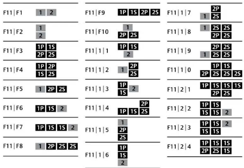
You can use the preset keys to configure the KM to support more than one monitor per channel following images detail the different preset monitor configurations.
NOTE: In the configurations, gray indicates a single computer and black indicates a multi-monit display. P indicates the primary display and S indicates the secondary display in a multi-monit configuration.
Figure 2.7 Two-Port KM Presets
text_image
Diagram showing eight F11-F18 configurations with labeled rows and columns, each containing a 2P, 1S, 2P, 2S, 1P, 1S, 2P, 2S, 1S, 2S, 2P, 2S, 1S, 2S, 2P, 2S, 1S, 2S, 2P, 2S, 1S, 2S, 2P, 2S, 1S, 2S, 2P, 2S, 1S, 2S, 2P, 2S, 1S, 2S, 1P, 1S, 2P, 2S, 1S, 2S, 2P, 2S, 1S, 2S, 2P, 2S, 1S, 2S, 2P, 2S, 1S, 2S, 2P, 2S, 1S, 2S, 2P, 2s, 1P, 1S, 2P, 2S, 1S, 2S, 2P, 2S, 1S, 2S, 2P, 2S, 1S, 2S, 2P, 2S, 1S, 2S, 2P, 2S, 1S, 2S, 2P, 2S, 1P, 1S, 2P, 2S, 1S, 2S, 2P, 2S, 1S, 2S, 2P, 2S, 1S, 2S, 2P, 2S, 1S, 2S, 2P, 2S, 1P, 1S, 2P, 2S, 1S, 2S, 3PFigure 2.8 Four-Port KM Presets

2.2 Keyboard and Mouse Settings
2.2.1 Keyboard settings
All secure switches block communication from the computers to the keyboard to prevent potential leaks. You can enable Caps Lock, Scroll Lock or Num Lock from a connected keyboard; however, connected keyboard status indicators do not illuminate to indicate the settings are enabled. The C: lock, Scroll lock and Num lock LEDs on the switch illuminate to indicate the settings are enabled specific channel. Switching channels changes the status of the LEDs if different settings are enabled each computer.
2.2.2 Mouse settings
When VDT is enabled, you can freeze mouse functionality on a selected channel to prevent inadve switching channels if the mouse approaches the screen border. The prevent transition feature allows to use the mouse to move objects such as windows and icons on a screen without unintentional dragging the object to another display. When the prevent transition feature is enabled and the left button is depressed, you can move objects only within the active display.
Using keyboard shortcuts, you can freeze or unfreeze the mouse on a selected channel, or increase decrease the speed of the mouse. See Keyboard Shortcuts on page 13 for a list of the keystroke combinations.
NOTE: The default mouse speed is set to 5 on a 1 to 10 speed scale.
2.2.3 Filtered USB port (fUSB)
Some models are equipped with a filtered USB port that only accepts authorized USB devices. When authorized USB device is connected to the fUSB port, the status LED on the front panel illuminates when an un-authorized USB device is connected to the fUSB console port, the status LED on the panel illuminates red. When switching between channels, the USB device connected to the fUSB port automatically switches. When switching to a channel that has no fUSB connection, the port remains mapped to the last channel that had a fUSB channel. To assign the fUSB port to a specific computer press the freeze USB button. Freeze USB prevents the fUSB from switching even when the keyboard video, mouse and audio peripherals switch between computers.
2.2.4 Interchangeable KVM to KM functionality
In KVM mode one display, keyboard, mouse, USB and audio peripheral set is shared between all computers. In KM mode, each computer is connected to a separate display while the keyboard are shared.
To change from KVM to KM mode:
- Disconnect the display from the KVM console port.
- Connect each computer directly to a separate display while keeping the keyboard, mouse, and audio peripherals connected to the KVM.
- Change the mouse mode by typing L Ctrl | L Ctrl | F11 | c.
To change from KM to KVM mode:
- Connect the display to the KVM console port.
- Connect each computer to the corresponding KVM computer video port.
- Change the mouse mode by typing L Ctrl | L Ctrl | F11 | b.
2.3 Keyboard Shortcuts
Keyboard shortcuts can be used to execute switch commands, load monitor presets and adjust mc settings. Keyboard shortcut functionality varies depending on the firmware version and the switch m
The style for sequential or concurrent keyboard shortcuts is typically Ctrl + Ctrl + F11. The following table
deviates from the style by eliminating the plus symbol between keystrokes. Unless otherwise noted, key combinations should be pressed concurrently and an L preceding Ctrl indicates the left control while an R preceding Ctrl indicates the right control key.
The following table details keyboard shortcut options.
Table 2.7 KM Keyboard Shortcuts
| KEY COMBINATION DESCRIPTION STANDARD SWITCHES VERSION 10020715 VERSION 10300915 VERSION 10020316 OR HIGHER KVM KM MINI-MATRIX | |||||||||||||||
| L Ctrl L Ctrl 1 Switch to channel 1 Y Y Y Y Y Y N | |||||||||||||||
| L CtrlL Ctrl2 | Switch to channel 2 | Y | Y | Y | Y | Y | Y | N | |||||||
| L CtrlL Ctrl3 | Switch to channel 3 | Y | Y | Y | Y | Y | Y | N | |||||||
| L CtrlL Ctrl4 | Switch to channel 4 | Y | Y | Y | Y | Y | Y | N | |||||||
| L CtrlL Ctrl5 | Switch to channel 5 | Y | Y | Y | Y | Y | Y | N | |||||||
| L CtrlL Ctrl6 | Switch to channel 6 | Y | Y | Y | Y | Y | Y | N | |||||||
| L CtrlL CtrlF11 B | Relative mouse mode | N | N | Y | Y | Y | Y | Y | |||||||
| L CtrlL CtrlF11 C | Absolute mouse mode | N | N | Y | Y | Y | Y | Y | |||||||
| L CtrlL Ctrl F | Video follow mouse (disable/enable) | N | N | Y | Y | Y | N | N | |||||||
| L CtrlL CtrlF11 R | System reset to factory default | N | Y | Y Y Y Y Y | Y | ||||||||||
| L CtrlR Ctrl B | Current channel DE is relative only | N | N | N | Y | Y | Y | Y | |||||||
| L CtrlR Ctrl C | Current channel DE is default | N | N | N | Y | Y | Y | Y | |||||||
| L CtrlR Ctrl Q | Disable/enable the copy and paste function | Y Y Y | Y Y | Y Y | |||||||||||
| L Ctrl Shift | Mouse will be ABS until released | N | Y Y Y | Y | |||||||||||
| L CtrlR Ctrl X | Exit terminal mode | N | Y | Y | Y | Y | Y | Y | |||||||
| L CtrlR Ctrl T | Enter terminal mode | N | Y | Y | Y | Y | Y | Y | |||||||
| L CtrlL CtrlF11 F | Disable switching by mouse | N | Y | Y Y Y | ^2 | Y | Y | ||||||||
| L CtrlL CtrlF11 U | Enable switching by mouse | N | Y | Y Y Y | ^2 | Y | Y | ||||||||
| L CtrlL CtrlF11 + | Increase mouse speed | N | Y | Y | Y | Y^2 | Y | Y | |||||||
| L CtrlL CtrlF11 - | Decrease mouse speed | N | Y | Y | Y | Y^2 | Y | Y | |||||||
| L CtrlL CtrlF11 F1 | Load preset 1 | N | Y | Y | Y | N | Y | N | |||||||
| L CtrlL CtrlF11 F2 | Load preset 2 | N | Y | Y | Y | N | Y | N | |||||||
| L CtrlL CtrlF11 F3 | Load preset 3 | N | Y | Y | Y | N | Y | N | |||||||
| L CtrlL CtrlF11 F4 | Load preset 4 | N | Y | Y | Y | N | Y | N | |||||||
| L CtrlL CtrlF11 F5 | Load preset 5 | N | Y | Y | Y | N | Y | N | |||||||
| L CtrlL CtrlF11 F6 | Load preset 6 | N | Y | Y | Y | N | Y | N | |||||||
| L CtrlL CtrlF11 F7 | Load preset 7 | N | Y | Y | Y | N | Y | N | |||||||
| L CtrlL CtrlF11 F8 | Load preset 8 | N | Y | Y | Y | N | Y | N | |||||||
| L CtrlL CtrlF11 F9 | Load preset 9 | N | Y | Y | Y | N | Y | N | |||||||
| L CtrlL CtrlF11 F10 | Load preset 10 | N | Y | Y | Y | N | Y | N | |||||||
| L CtrlL CtrlF11 1-3 1-0 | Load preset 1-3 or 1-0 | N | Y | Y | Y | N | Y | N | |||||||
| L CtrlL CtrlF11 F12 | Load previously loaded preset | N | Y | Y | Y | N | Y | N | |||||||
| L CtrlL CtrlF11 L 1 | Load layout 1 | N | N | N | Y | N | N | Y | |||||||
| L CtrlL CtrlF11 L 2 | Load layout 2 | N | N | N | Y | N | N | Y | |||||||
Table 2.7 KM Keyboard Shortcuts (continued)
| KEY | COMBINATION | DESCRIPTION | STANDARD SWITCHES | VERSION 10020715 | VERSION 10300915 | VERSION 10020316 OR HIGHER | KVM | KM | MINI-MATRIX |
| L | Ctrl L Ctrl F11 L 3 | Load layout 3 | N | N | N | Y | N | N | Y |
| L | Ctrl L Ctrl F11 L 4 | Load layout 4 | N | N | N | Y | N | N | Y |
| L | Ctrl L Ctrl F11 L 5 | Load layout 5 | N | N | N | Y | N | N | Y |
| L | Ctrl L Ctrl F11 L 6 | Load layout 6 | N | N | N | Y | N | N | Y |
| L | Ctrl L Ctrl F1 | 1-4 monitor Display 1 | channelY 1-4 on | N | N | Y | N | N | Y |
| L | Ctrl L Ctrl F2 | 1-4 monitor Display 2 | channelY 1-4 on | N | N | Y | N | N | Y |
^1 You must press and hold this keyboard shortcut to execute the command.
^2 This command is only available when the switch is in KM mode.
2.4 KM Configuration
The KM configuration utility is a web-based tool that allows system administrators to define custom monitor setups in a KM configuration file. The file is saved with the .kmc extension. When configuring a KM switch using a KM configuration file, you must be logged in to the switch as administrator.
The KM configuration utility allows administrators to define the number of monitors connected to each computer. Monitors can vary in size and resolution, and can be arranged in multiple layouts. You must download and install the KM configuration utility from the Software Downloads section on the Vertiv web site.
The KM configuration utility operates only with Microsoft® Windows®. Before downloading and installing the KM configuration utility, ensure at least Microsoft® Windows® XP is installed on the computers to be connected. The following browsers support the KM configuration utility:
• Google Chrome 20.0 or higher
• Microsoft® Internet Explorer®
- Mozilla® Firefox®
Before creating a KM configuration file, verify the number of computers and monitors to be connected to the KM switch and the monitors' sizes and resolutions.
2.4.1 Creating a KM configuration file
A KM configuration file is referred to in the KM configuration utility interface as a KM configuration project. Each customized setup requires its own project. You can create projects using the KM configuration utility project wizard. After completing the steps in the wizard, the KM configuration file is generated and downloaded to the computer.
The following table lists guidelines for entering project file information.
| CONFIGURATION FIELD | DESCRIPTION |
| Project Name | Name of the custom monitor configuration. |
| Product Model | Model of the KM switch. |
| Mouse Speed | Default mouse cursor speed for all systems. Changes in the mouse cursor speed value on each computer do not affect the |
CONFIGURATION DESCRIPTION FIELD
KM switch's mouse cursor speed.
Mouse Acceleration Rate at which the mouse cursor speed increases. Changes in the mouse cursor acceleration value on each computer do not affect the KM switch's mouse cursor acceleration.
Number of Computers Total number of computers to be connected to the KM switch for a particular configuration.
To create a new KM configuration project:
- Log in to the KM switch as administrator, launch the KM configuration utility and click N Project.
- Enter the project name and number of computers into the fields on the KM project setup window.
- Select the product model, mouse speed and mouse acceleration from the drop-down menu and click Next Step.
Figure 2.9 KM Project Setup Window
KM Project Setup
Enter general information about the project configuration.
General Setup
Project Name:
New KM Project
Product Model:
K304
Mouse Speed:
5 - Default
Mouse Acceleration:
5 - Default
Number of computers:
2
- Enter a detailed product description that explains the configuration and click Next Step.
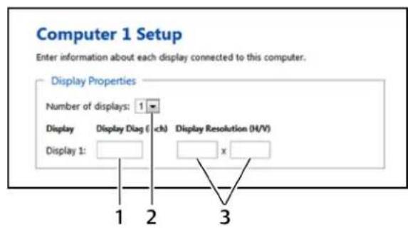
- For each computer, select the number of monitors from the drop-down menu, enter each monitor's size and resolution and then click Next Step.
NOTE: Multiple monitor configurations require additional steps. See Multiple monitor setup on page 20 for more information.
NOTE: If a monitor is set to portrait orientation, enter the native resolution accordingly. For a monitor with 1680 × 1050 native resolution would have a 1050 × 1680 resolution in portrait or
Figure 2.10 Computer Setup Window
text_image
Computer 1 Setup Enter information about each display connected to this computer. Display Properties Number of displays: 1 Display Display Diag ( ch) Display Resolution (H/V) Display 1: 1 2 3Table 2.8 Computer Setup Window
| ITEM | DESCRIPTION |
1 Monitor size
2 Number of displays
3 Native monitor resolution
- Configure the location of the monitors by dragging and dropping the monitors into position. See Configuration examples on page 17 for acceptable multiple monitor setups.
- Click Complete Setup to generate and download the configuration file.
Configuration examples
Each monitor is labeled with its computer number and monitor number in the KM configuration u. The monitors can be touching or separated by distance based on the geometry settings required.
After the monitors are placed into a layout, a bridge between the two monitors is shown in yel indicate the mouse cursor area for switching monitors. Clicking the yellow area removes it from the configuration and you will not be able to switch between the monitors using the mouse cursor.
Example 1
The monitor configuration in example 1 establishes a mouse cursor bridge between the bottom left of display 1 and the top right corner of display 2. The mouse cursor bridge is indicated by the and it is the only area where the mouse switching between the two monitors is enabled. When cursor switches from display 1 to display 2, the active computer switches from computer 1 to co respectively. The red lines indicate areas where mouse cursor switching is disabled.
Figure 2.11 Example 1 Physical Layout
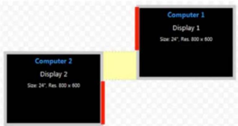
text_image
Computer 1 Display 1 Size: 24", Res. 800 x 600 Computer 2 Display 2 Size: 24", Res. 800 x 600Example 2
Both monitor configurations in example two enable you to switch between display 1 on the left a 2 on the right. Using the mouse cursor to switch from display 1 to display 2 also switches your computer 1 to computer 2.
Figure 2.12 Example 2 Physical Layout
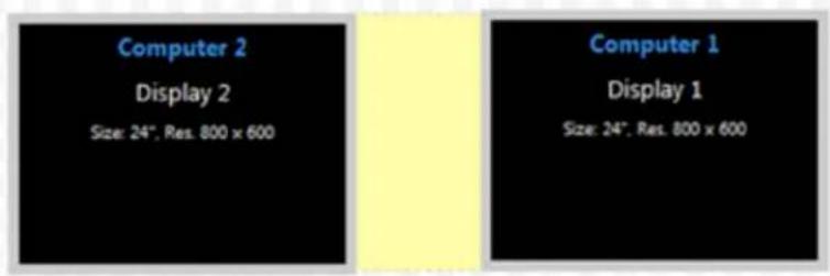
text_image
Computer 2 Display 2 Size: 24", Res. 800 x 600 Computer 1 Display 1 Size: 24", Res. 800 x 600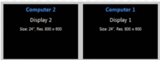
text_image
Computer 2 Display 2 Size: 24", Res. 800 x 600 Computer 1 Display 1 Size: 24", Res. 800 x 600Example 3
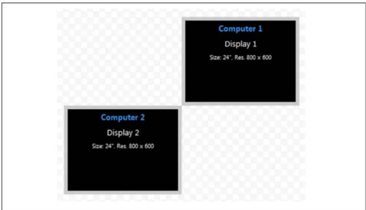
Example 3 depicts a multiple monitor configuration with the monitors connected at the corners. Ex 3A is an invalid configuration because display 1 and display 2 do not share an overlapping area mouse cursor can cross. Example 3B is valid since the two monitors overlap to create an area mouse cursor can cross.
Figure 2.13 Example 3A Invalid Physical Layout
text_image
Computer 1 Display 1 Size: 24", Res. 800 x 600 Computer 2 Display 2 Size: 24", Res. 800 x 600Figure 2.14 Example 3B Valid Physical Layout
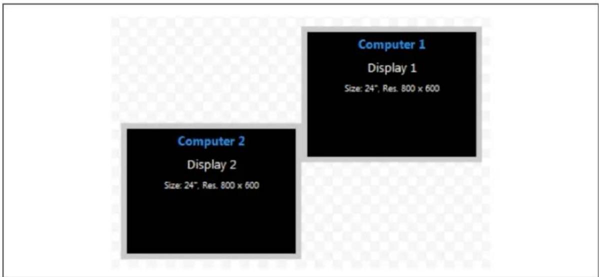
text_image
Computer 1 Display 1 Size: 24", Res. 800 x 600 Computer 2 Display 2 Size: 24", Res. 800 x 600Example 4
In example 4, the physical placement of the monitors can be configured multiple ways. In the first computer 2 has two connected monitors and mouse cursor switching is enabled between computer both computer 2 monitors. In the second layout, mouse cursor switching is enabled only between computer 1 and display 1 for computer 2.
Figure 2.15 Example 4 Physical Layouts
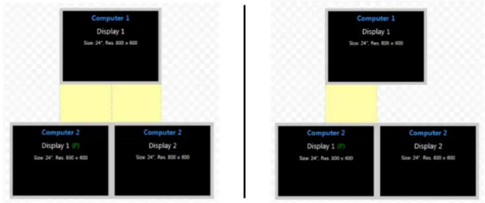
text_image
Computer 1 Display 1 Size: 24", Res. 800 x 600 Computer 2 Display 1 (P) Size: 24", Res. 800 x 600 Computer 2 Display 2 Size: 24", Res. 800 x 600 Computer 1 Display 1 Size: 24", Res. 800 x 600 Computer 2 Display 1 (P) Size: 24", Res. 800 x 600 Computer 2 Display 2 Size: 24", Res. 800 x 600Multiple monitor setup
In a multiple monitor configuration, the KM configuration file and the Microsoft® extended desktop settings control switching between the monitors. When setting up a multiple monitor configuration, y must enter the Microsoft® virtual desktop parameters to ensure a smooth and proportional transition among all connected monitors.
All monitors connected to the same computer must be configured next to one another with no between the monitors.
To set up a multiple monitor configuration:
- From the Start menu, click Control Panel, then click Appearance and Personalization - Display - Adjust Resolution.
- In the KM configuration utility Display Properties window, enter the size and resolution information for the primary and secondary monitors as indicated in the Microsoft® extended desktop settings.
- Enter the vertical and horizontal coordinates for monitors.
The following figure and table list the monitor property fields to be completed when configuring r monitors.
Figure 2.16 Entering Data for a Multiple Monitor Configuration
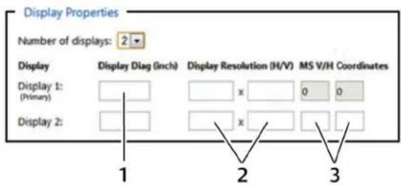
text_image
Display Properties Number of displays: 2 Display Display Diag (Inch) Display Resolution (H/V) MS V/H Coordinates Display 1: (Primary) x 0 0 Display 2: x 1 2 3Table 2.9 Multiple Monitor Configuration Properties
ITEM DESCRIPTION
1 Monitor size
2 Native monitor resolution
3 Monitor coordinates per the Microsoft® extended desktop settings
2.4.2 Loading a KM configuration file
Before you can upload the KM configuration file, you must have the following:
- Loading driver mapping file - An .inf file that maps Microsoft® drivers to be used by the switch in administrator mode.
- USB programming cable - The cable required to load configurations onto the switch and is connected to the switch's USB mouse port.
NOTE: The cable will not work if connected to any port other than the USB mouse port.
- Administrator credentials - You must be logged in as administrator to load the KM configuration file onto the switch.
To load the KM configuration file:
- Ensure power to the switch is turned on and a valid keyboard is connected to the sw keyboard port.
- Launch administrator mode by pressing L CTRL + R CTRL + T while in terminal mode.
- Select KM Configuration Option and log in as administrator.
- Connect one end of the USB programming cable to the mouse port on the switch and the other end to the computer that has the KM configuration file, the loading utility an mapping file.
- Open the loading utility and verify that the switch is recognized.
- Click Select a new configuration file and select the KM configuration file to be loaded.
- Click Update KM and restart the switch.
The following figure and table list the items shown on the KM configuration utility load interface.
Figure 2.17 KM Configuration Utility Load Interface
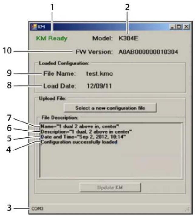
text_image
KM Ready Model: K304E FW Version: A0AB000000010304 Loaded Configuration: File Name: test.kmc Load Date: 12/09/11 Upload File: Select a new configuration file File Description: Name="1 dual 2 above in, center" Description="1 dual, 2 above in center" Date and Time="Sep 2, 2012, 10:14" Configuration successfully loaded Update KM COM3Table 2.10 KM Configuration Utility Load Interface Items
| ITEM DESCRIPTION | |
| 1 | KM configuration utility status |
| 2 | Switch model detected by the KM configuration utility |
| 3 | Connected port |
| 4 | Configuration file load status |
| 5 | Date the configuration file was created |
| 6 | Description of the configuration file |
| 7 | Configuration filename |
| 8 | Load date of the configuration file |
| 9 | Filename of the last loaded configuration |
| 10 | Switch's firmware version detected by the KM configuration utility |
3 TROUBLESHOOTING
When power is turned on to the switch, it performs a self-test to verify normal operation. If the self-test procedure, all channel LED buttons flash on and off once and a combination of LEDs illuminate. The various combinations of illuminated LEDs indicate the fault with the switch. After failed self-test, the switch becomes inoperable until the fault is resolved.
3.1 General
The following table lists general faults, the fault indicators and the actions to resolve each fault.
Table 3.1 General Switch Faults
| FAULT INDICATOR RESOLUTION | |
| The switch did not pass self-test. Allthechannel LED buttons Turn power off and on to the switch.flash on and off once and a combination of LEDsilluminate to indicate the fault. | |
| The switch is not receiving power. The displays do not show ensure the power cable is intact and connected to the switch and to the power source video output and none the table is damaged, replace it.front panel LEDs illuminate. | |
| The switch enclosure is compromised. The tamper-evident seals immediately remove the switch from service and contact Technical Support.indicate intrusion, the switch is inoperable and all channel LED buttons flash continuously. | |
| Remote desktop control The switch does not Disconnect from remote desktop control, or control the KVM through remote desktop connected and rendering respond when the channel control or keyboard shortcuts.the channel select buttons select buttons are pressed.is inoperable. |
3.2 KM Configuration File
The two most common errors that occur when loading the KM configuration file include:
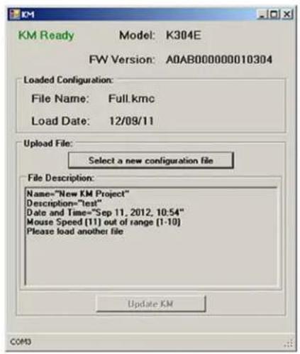
- Incorrectly formatted configuration file - When you load an incorrectly formatted file, the KM configuration utility load interface indicates the issue in the File Description section and prompts you to load another file. Ensure the files you load are created with the KM configuration utility and have not been manually modified.
Figure 3.1 KM Configuration Utility Load Interface with Configuration File Error
text_image
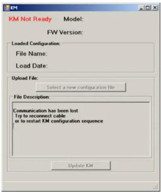
KM Ready Model: K304E FW Version: A0AB000000010304 Loaded Configuration: File Name: Full.kmc Load Date: 12/09/11 Upload File: Select a new configuration file File Description: Name="New KM Project" Description="test" Date and Time="Sep 11, 2012, 10:54" Mouse Speed [T1] out of range [1-10] Please load another file Update KM COM3- Invalid communication connection to the switch - When communication between the switch and the utility is lost or fails, the KM configuration utility load interface status is KM Not Ensure that you use a USB programming cable to connect the switch to the computer runs the configuration utility and the cable is connected to the switch's USB mouse port. verify that the loading driver mapping file is installed on the computer. If the connection continues to fail, restart the switch and relaunch administrator mode.
Figure 3.2 KM Configuration Utility Load Interface with Failed Connection Error
text_image
KM Not Ready Model: FW Version: Loaded Configuration: File Name: Load Date: Upload File: Select a new configuration file File Description: Communication has been lost Try to reconnect cable or to restart KM configuration sequence Update KM3.3 Video
The following table lists video faults, the fault indicators and the action to resolve each fault.
Table 3.2 Video Faults
| FAULT INDICATOR RESOLUTION | ||
| The connected video display is not qualified. | The video diagnostic LED flashes green and display is inoperable. | Turn off and disconnect the non-qualified display and connect and turn power on to a qualified display. |
| The displays or the computers are not connected to the switch and the display diagram properly or the connecting cables or ports are damaged. | The displays do not show video output on any connection cables does not appear green. | Ensure the displays are properly connected to the switch and the displays and connecting cables are not damaged. Replace damaged cables. If the displays or connections are damaged, replace the damaged parts. If the issue persists, check solid displays' on-screen menu to ensure the correct source is selected and verify the video mode and computer's video mode are the same. If the problem persists and the LED does not illuminate solid green, change the entire display unit or contact Technical Support. |
| A specific computer is rated display does not be connected to the switch video output for a specified properly or the connecting channel. cable or port is damaged. | Ensure the connecting cable between the computer and the switch is secured and not damaged. Replace damaged cables. Ensure the displays are compatible with the computer resolution and refresh rate settings. Verify the video output is available and an image is shown when the display unit is connected directly to the computer. If the problem persists, turn power off and on to the switch, reboot the computer, replace the display unit or contact Technical Support. | |
| The displays or computers are not connected to the experiencing poor video switch properly or the image quality and the connecting cables are not displayed diagnostic LED compatible with the does not appear solid displays. | Ensure the displays are properly connected to the switch and the displays and connecting cables are compatible with the displays and not damaged. Replace damaged cables. Video cable length should not exceed 15 feet. Ensure the displays are compatible with the computer resolution and refresh rate settings. Lower the video resolution of the computer. Verify the video output is available and an image is shown when the display is connected directly to the computer. If the problem persists, turn power off and on to switch, reboot the computers and displays, replace the video displays or contact Technical Support. | |
3.4 Keyboard
The following table lists keyboard faults, the fault indicators and the action to resolve each fault.
Table 3.3 Keyboard Faults
| FAULT INDICATOR RESOLUTION | |
| The keyboard is not The keyboard does not connected to the switch work on any channels. properly or the keyboard cable or port is damaged. | Ensure the keyboard is properly connected to the switch and the USB cable between the keyboard and the switch is not damaged. If the issue persists, connect the keyboard to different port or use a different standard, non-wireless, qualified keyboard. Ensure the driver for the keyboard is installed on the computer.NOTE: If the computer is returning from standby mode, allow up to one minute for the computer to regain keyboard functionality. |
| The keyboard, mouse and the keyboard and mouse video cables are connected not working on two switches to two different computer channels. | Ensure the keyboard/mouse and video cables are connected to the correct ports on the software. For example, the keyboard and mouse cable and the video cable for computer 1 should be connected to ports specifically designated for computer 1. |
| The computer does not The keyboard does not recognize the connected work on one channel. | |
| The connected keyboard not qualified or not connected to the switch properly | Ensure the keyboard is properly connected to the switch and the USB cable between the keyboard and the switch is not damaged. If damaged, replace the cable. Ensure the keyboard and the switch is a qualified device. If not, disconnect the non-qualified keyboard and connected to produce keystrokes on the qualified keyboard. Verify that the keyboard works connected directly to the computer or screen when using the keyboard. When connected to a different USB port. If the problem persists, turn power off and on the switch, reboot the computer, and replace the keyboard unit or contact Technical Support. |
| Caps lock, Scroll lock and Num lock LEDs do not lock or Num lock keys are the keyboard to prevent potential data leaks. To determine if Caps lock, Scroll lock illuminate on the keyboard addressed, the corresponding Num lock are enabled on a specific computer, press the channel select button on the keyboard LEDs do not switch and observe the Caps lock, Scroll lock and Num lock LEDs on the switch. | |
| The connected keyboard not compatible with the switch. | Certain keyboard functions Determine if the connected keyboard is compatible with the switch. Some non-standard function is disabled by the switch for security purposes. Contact Technical connected to the switch.Support for compatibility information. |
3.5 Mouse
The following table lists mouse faults, the fault indicators and the action to resolve each fault.
Table 3.4 Device Faults
| FAULT INDICATOR RESOLUTION | |
| The connected mouse is Timet mouse is non-functional and the mouse cursor is frozen on the screen. You are unable to use the mouse to move the mouse cursor. | Disconnect the non-qualified mouse and connect a qualified mouse. |
| The mouse is not plugged the mouse does not write to any channels but not verify that the mouse is plugged into the mouse port and the connecting cable is not damaged. Plug the mouse into the mouse port if it is connected to a non-mouse port replace the cable if it is damaged. | the mouse is not plugged the mouse does not write to any channels but not verify that the mouse is plugged into the mouse port and the connecting cable is not damaged. Plug the mouse into the mouse port if it is connected to a non-mouse port replace the cable if it is damaged. |
| The mouse is not connected the mouse does not write to the switch properly on their channels. Ensure the mouse is properly connected to the switch and the USB cable between the mouse and the switch is not damaged. If the issue persists, connect the mouse to a different port or use a different standard, non-wireless, qualified mouse. Ensure the driver for the mouse is installed on the computer. | mouse cable or port is damaged. Ensure the mouse is properly connected to the switch and the USB cable between the mouse and the switch is not damaged. If the issue persists, connect the mouse to a different port or use a different standard, non-wireless, qualified mouse. Ensure the driver for the mouse is installed on the computer. |
| NOTE: If the computer is returning from standby mode, allow up to one minute for the computer to regain mouse functionality. | |
| The computer does not The mouse does not write to the computer's Device Manager wizard to troubleshoot and resolve the issue. | recognize the connected on one channel. |
3.6 DPP
The following table lists DPP device faults, the fault indicators and the action to resolve each fa
Table 3.5 Device Faults
| FAULT INDICATOR RESOLUTION | |
| The connected USB device is not qualified. DPP LED flashes green and disconnect the non-qualified USB device and connect a qualified USB device is inoperable. | |
| The USB device is not DPP USB device is not working properly or the working on a channel. Ensure the USB device is working properly when connected directly to the computer and connecting cable between the computer and the DPP input port on the switch is damaged or missing. | |
| The USB device and video DPP USB device is not cables are connected to working on two channels. Ensure the USB device and video cables are connected to the correct ports on the different computers. For example, the USB device cable and the video cable for computer 1 should connected to ports specifically designated for computer 1. | |
| The USB device is not DPP USB device is not working properly or not working on all channels. Ensure there is a USB connected cable between the computer and the relevant DPP connected to the computer. |
4 APPENDICES
The appendix contains technical specification tables for all the products covered in this document.
Table A.1 SC 820/820D/820H/920/920D/920H 2-port, single or dual-head KVM Switches
| CATEGORY VALUE | |
| Dimensions | |
| SC 920 SeriesW x D x H | 7 x 2.4 x 2 in (177 x 61 x 52.6 mm) |
| SC 820 SeriesW x D x H | 7 x 2.4 x 1.4 in(177 x 61 x 35.2 mm) |
| SC 920 SeriesWeight | 1.1 lbs (0.5 kg) |
| SC 820 SeriesWeight | 1.1 lbs (0.5 kg) |
| Ports | |
| CPU Keyboard/Mouse Ports USB Type-B jack | |
| Console Keyboard Input USB Type-A female connector | |
| CPU Audio Input 1/8 in (3.5 mm) stereo jack | |
| CPU Video Input Port DVI-I video port (2 for SC 920, 1 for SC 820 model)DisplayPort video port(2 for SC 920D, 1 for SC 820D model )HDMI video port(2 for SC 920H, 1 for SC 820 model) | |
| Console Mouse Input USB Type-A female connector | |
| Console Display Port DVI-I female connector (2 for SC 920, 1 for SC 820)DisplayPort female connector (2 for SC 920D, 1 for SC 820D)HDMI female connector (2 for SC 920H,1 for SC 820H) | |
| Front Panel | |
| Port Selectors and LEDs | 2 |
| Resolution/Displays | |
| Resolution | Upto 4Kx2K Ultra HD (3840 X 2160 Pixels) resolutions |
| Supports Displays | 2 for the SC 920 series1 for the SC 820 series |
| Support | |
| Secure Channels | 2 |
| Users Supported | 1 |
| Number of Computers | 2 |
| Power | |
| DCInput Range | 12 VAC |
| Ambient Atmospheric Condition Ratings | |
| Operating Temperature | 32° to 104° F (0° to 40° C) |
| Storage Temperature | -4° to 140° F (-20° to 60° C) |
| Humidity | 0-80% relative humidity, non-condensing |
Table A.2 SC 840D/845D/940D/945D 4-Port DisplayPort KVM Switches
| CATEGORY VALUE | |
| Dimensions | |
| W x D x H 13.5 x 5 x 2.2 in (342 x 125 x 56.6 mm) | |
| Weight 2.2 lbs. (1 kg) | |
| Ports | |
| Console Audio Out 1/8 in (3.5 mm) stereo jack | |
| CPU Keyboard/Mouse Ports USB Type-B jack | |
| CPU DPP Ports USB Type-B jack | |
| Console DPP Input USB Type-A female connector | |
| Console Video Out port 1 HDMI dual-link female connector | |
| Console Keyboard Input USB Type-A female connector or PS/2 Mini-DIN 6-pin female connector | |
| CPU Audio Input 1/8 in (3.5 mm) stereo jack | |
| CPU Video Input Port | DVI-I dual-link female connector |
| Console Mouse Input | USB Type-A female connector or PS/2 Mini-DIN 6-pin female connector |
| Console CAC Input USB Type-A female connector | |
| Front Panel | |
| Port Selectors | 4 |
| LED Indicators | 4 |
| Resolution/Displays | |
| Resolution | Up to 2560 x 1600 |
| Supports Displays | 1 single-link/dual-link digital DVI-D display; analog VGA display or HDMI with adaptor |
| Support | |
| Secure Channels | 4 |
| Users Supported | 1 |
| Number of Computers | 4 |
| Power | |
| AC Input Range | 100-240 VAC |
| Ambient Atmospheric Condition Ratings | |
| Operating Temperature | 32° to 104° F (0° to 40° C) |
| Storage Temperature | -4° to 140° F (-20° to 60° C) |
| Humidity | 0-80% relative humidity, non-condensing |
| Additional Information | |
| Warranty | 2 years; can be extended to up to 7 years at cost |
| Security Accreditation | Common Criteria EAL 4+ |
Table A.3 SC 840H/845H/940H/945H 2- and 4-Port HDMI KVM Switches
| CATEGORY VALUE | |
| Dimensions | |
| W x D x H 13.5 x 5 x 2.2 in (342 x 125 x 56.6 mm) | |
| Weight 4 lbs (1.85 kg) | |
| Ports | |
| Console Audio Out 1/8 in (3.5 mm) stereo jack | |
| CPU Keyboard/Mouse Ports USB Type-B jack | |
| CPU DPP Ports USB Type-B jack | |
| Console DPP Input USB Type-A female connector | |
| Console Video Out Port 1 HDMI dual-link female connector | |
| Console Keyboard Input USB Type-A female connector or PS/2 Mini-DIN 6-pin female connector | |
| CPU Audio Input 1/8 in (3.5 mm) stereo jack | |
| CPU Video Input Port HDMI female connector | |
| Console Mouse Input USB Type-A female connector or PS/2 Mini-DIN 6-pin female connector | |
| Console Display Port 1 HDMI female connector [2 in SC845H] | |
| Console CAC Input USB Type-A female connector | |
| Front Panel | |
| Port Selectors 4 | |
| LED Indicators 4 channel + 4 DPP | |
| Resolution/Displays | |
| Resolution All HDMI 1.3a resolutions up to 1920 × 1200 × 30 bpp@60 Hz | |
| Supports Displays 1 HDMI or 1 DVI-D display with adaptor [2 displays in SC845H] | |
| Support | |
| Secure Channels 4 | |
| Users Supported 1 | |
| Number of Computers 4 | |
| Power | |
| AC Input Range 100-240 VAC | |
| Ambient Atmospheric Condition Ratings | |
| Operating Temperature 32° to 104° F (0° to 40° C) | |
| Storage Temperature -4° to 140° F (-20° to 60° C) | |
| Humidity 0-80% relative humidity, non-condensing | |
| Additional Information | |
| Warranty 2 years; can be extended to up to 7 years at cost | |
| Security Accreditation Common Criteria EAL 4+ |
Table A.4 SC 840/845/940/945 DVI-I KVM Switches
| CATEGORY VALUE | |
| Dimensions | |
| W x D x H 13.5 x 5 x 2.2 in (342 x 125 x 56.6 mm) | |
| Weight 4 lbs (1.85 kg) | |
| Ports | |
| Console Audio Out 1/8 in (3.5 mm) stereo jack | |
| CPU Keyboard/Mouse Ports USB Type-B jack | |
| CPU DPP Ports USB Type-B jack | |
| Console DPP Input USB Type-A female connector | |
| Console Video Out Port 2 DVI-I dual-link female connector | |
| Console Keyboard Input USB Type-A female connector or PS/2 Mini-DIN 6-pin female connector | |
| CPU Audio Input 1/8 in (3.5 mm) stereo jack | |
| CPU Video Input Port HDMI female | |
| Console Mouse Input USB Type-A female connector or PS/2 Mini-DIN 6-pin female connector | |
| Console Display Port 1 HDMI female connector [2 in SC845H] | |
| Console CAC Input USB Type-A female connector | |
| FrontPanel | |
| Port Selectors 4 | |
| LED Indicators 4 channel + 4 DPP | |
| Resolution/Displays | |
| Resolution Dual-link DVI upto 2560 x 1600 | |
| Supports Displays 2 single-link and dual-link digital DVI-D displays; analog VGA monitors with adaptor | |
| Target Video Connectors All of the target video connectors and cable connectors on the switch are DVI-I. Target devices with analog connectors require an adaptor to connect to the VGA port (VAD-28). Target devices with digital only connectors must use an adaptor to match the DVI-D port (VAD-31). | |
| Support | |
| Secure Channels 4 | |
| Users Supported 1 | |
| Number of Computers 4 | |
| Hardware The SC switches support most DVI, HDMI, VGA monitors and video cards (with adaptors),headsets, speakers, USB and PS/2 keyboards and USB mice. | |
| Power | |
| AC Input Range 100-240 VAC | |
| Ambient Atmospheric Condition Ratings | |
| Operating Temperature 32° to 104° F (0° to 40° C) | |
| Storage Temperature -4° to 140° F (-20° to 60° C) | |
| Humidity 0-80% relative humidity, non-condensing | |
| Additional Information | |
| Warranty 3 years; can be extended to up to 7 years at cost | |
| Security Accreditation Common Criteria EAL 4+ |
Table A.5 SC KM 140/KM 145 4-Port KM Switches
| CATEGORY VALUE | |
| Dimensions | |
| W x D x H 13.5 x 5 x 1.1 in(342 x 125 x 28 mm) | |
| Weight 3 lbs (1.4 kg) | |
| Ports | |
| Console Audio Out 1/8 in (3.5 mm) stereo jack | |
| Computer Keyboard/Mouse Ports USB Type-B jack | |
| Console Keyboard Input USB Type-A female connector or PS/2 Mini-DIN 6-pin female connector | |
| CPU Audio Input 1/8 in (3.5 mm) stereo jack | |
| Console Mouse Input USB Type-A female connector or PS/2 Mini-DIN 6-pin female connector | |
| Console CAC Input USB Type-A | |
| FrontPanel | |
| Port Selectors | 4 |
| LED Indicators | 4 channel + 4 DPP |
| User Channel Selection Methods | Front panel push-buttons, SCS |
| Support | |
| Users Supported | 1 |
| Number of Computers | 4 |
| Power | |
| AC Input Range | 100-240 VAC |
| Power Requirements | 100-240 VAC, 0.9A Freq. 50/60 Hz |
| AmbientAtmospheric Condition Ratings | |
| Operating Temperature | 32° to 104° F (0° to 40° C) |
| Storage Temperature | -4° to 140° F (-20° to 60° C) |
| Humidity | 0-80% relative humidity, non-condensing |
| Administrator Settings | Display physical size, display resolution X / Y, display orientation (portrait /landscape), display head (1st, 2nd,16th), display location (coordinates), mouse speed (1-10), mouse acceleration (1-10), SCS enable / disable, prevent transition while dragging - enable / disable. |
| Additional Information | |
| Warranty | 2 years; can be extended to up to 7 years at cost |
| Security Accreditation | Common Criteria EAL 4+ |
Table A.6 SC KM 120 2-Port KM Switches
| CATEGORY VALUE | |
| Dimensions | |
| W x D x H 6.96 x 2.9 x 1.1 in (177 x 74 x 30 mm) | |
| Ports | |
| Console Audio Out 1/8 in (3.5 mm) stereo jack | |
| Computer Keyboard/Mouse Ports USB Type-B jack | |
| Console Keyboard Input USB Type-A female connector | |
| CPU Audio Input 1/8 in (3.5 mm) stereo jack | |
| Console Mouse Input USB Type-A female connector | |
| FrontPanel | |
| Port Selectors 2 | |
| LED Indicators 2 channel | |
| User Channel Selection Methods | Front panel push-buttons, or VDT |
| Support | |
| Users Supported | 1 |
| Number of Computers | 2 |
| Power | |
| Power Requirements | DC input 12 V/1.5 A maximum |
| AmbientAtmospheric Condition Ratings | |
| Operating Temperature | 32° to 104° F (0° to 40° C) |
| Storage Temperature | -4° to 140° F (-20° to 60° C) |
| Humidity | 0-80% relative humidity, non-condensing |
| Administrator Settings | Display physical size, display resolution X/Y, display orientation (portrait/landscape), display head (1st, 2nd,16th), display location (coordinates), mouse speed (1-10), mouse acceleration (1-10), SCS enable/disable, prevent transition while dragging - enable/disable. |
| Additional Information | |
| Warranty | 2 years; can be extended to up to 7 years at cost |
| Security Accreditation | Common Criteria EAL 4+ |
Table A.7 SC 920XD 2-Port Dual-Head KVM Switches
| CATEGORY VALUE | |
| Dimensions | |
| W x D x H 7 x 2.4 x 2 in (177 x 61 x 52.6 mm) | |
| Ports | |
| Console Audio Out 1/8 in (3.5 mm) stereo jack | |
| Computer Keyboard/Mouse Ports USB Type-B jack | |
| Console Keyboard Input USB Type-A female connector | |
| CPU Audio Input 1/8 in (3.5 mm) stereo jack | |
| Console Video Out Port DisplayPort and DVI-I | |
| CPU Video Input Port DisplayPort and DVI-I | |
| Console Mouse Input USB Type-A female connector | |
| FrontPanel | |
| Port Selectors | 2 |
| LED Indicators | 2 channel |
| User Channel Selection Methods | Front panel push-buttons, or VDT |
| Support | |
| Users Supported | 1 |
| Number of Computers | 2 |
| Power | |
| Power Requirements DC input 12 V/1.5 A maximum | |
| AmbientAtmospheric Condition Ratings | |
| Operating Temperature | 32° to 104° F (0° to 40° C) |
| Storage Temperature | -4° to 140° F (-20° to 60° C) |
| Humidity | 0-80% relative humidity , non-condensing |
| Administrator Settings | Display physical size, display resolution X/Y, display orientation (portrait/landscape), display head (1st, 2nd,16th), display location (coordinates), mouse speed (1-10), mouse acceleration (1-10), SCS enable/disable, prevent transition while dragging - enable/disable. |
| Additional Information | |
| Warranty | 2 years; can be extended to up to 7 years at cost |
| Security Accreditation | Common Criteria EAL 4+ |
Table A.8 SC 945XD 4-Port Mixed Dual-Head KVM Switches
| CATEGORY VALUE | |
| Dimensions | |
| W x D x H 13.5 x 5 x 2.2 in (342 x 125 x 56.6 mm) | |
| Ports | |
| Console Audio Out 1/8 in (3.5 mm) stereo jack | |
| Computer Keyboard/Mouse Ports USB Type-B jack | |
| Console Keyboard Input USB Type-A female connector or PS/2 Mini-DIN 6-pin female connector | |
| CPU Audio Input 1/8 in (3.5 mm) stereo jack | |
| Console Video Out Port DisplayPort and DVI-I | |
| CPU Video Input Port DisplayPort and DVI-I | |
| Port Selectors 4 | |
| LED Indicators | 4 channel |
| User Channel Selection Methods | Front panel push-buttons, or VDT |
| Support | |
| Users Supported | 1 |
| Number of Computers | 4 |
| Power | |
| AC Input Range | 100-240 VAC |
| AmbientAtmospheric Condition Ratings | |
| Operating Temperature | 32° to 104° F (0° to 40° C) |
| Storage Temperature | -4° to 140° F (-20° to 60° C) |
| Humidity | 0-80% relative humidity , non-condensing |
| Administrator Settings | Display physical size, display resolution X/Y, display orientation (portrait/landscape), display head (1st, 2nd,16th), display location (coordinates), mouse speed (1-10), mouse acceleration (1-10), SCS enable/disable, prevent transition while dragging - enable/disable. |
| Additional Information | |
| Warranty | 2 years; can be extended to up to 7 years at cost |
| Security Accreditation | Common Criteria EAL 4+ |

VERTIV™

VERTIV™
VertivCo.com | Vertiv Headquarters, 1050 Dearborn Drive, Columbus, OH, 43085, USA
© 2018 Vertiv Co. All rights reserved. Vertiv and the Vertiv logo are trademarks or registered trademarks of Vertiv Co. All other names and logos referred to are trade names, trademarks or registered trademarks of their respective owners. While every precaution has been taken to ensure accuracy and completeness herein, Vertiv Co. assumes no responsibility, and disclaims all liability, for damages resulting from use of this information or for any errors or omissions. Specifications are subject to change without notice.