GPS 95AVD - Gps GARMIN - Free user manual and instructions
Find the device manual for free GPS 95AVD GARMIN in PDF.

User questions about GPS 95AVD GARMIN
0 question about this device. Answer the ones you know or ask your own.
Ask a new question about this device
Download the instructions for your Gps in PDF format for free! Find your manual GPS 95AVD - GARMIN and take your electronic device back in hand. On this page are published all the documents necessary for the use of your device. GPS 95AVD by GARMIN.
USER MANUAL GPS 95AVD GARMIN
© 1993 GARMIN, 9875 Widmer Road, Lenexa, KS 66215, USA
Printed in Taiwan.
All rights reserved. No part of this manual may be reproduced or transmitted in any form or by any means, electronic or mechanical, including photocopying and recording, for any purpose without the express written permission of GARMIN.
Information in this document is subject to change without notice. GARMIN reserves the right to change or improve their products and to make changes in the content without obligation to notify any person or organization of such changes or improvements.
June, 1993 190-00050-00 Rev. A
PREFACE
GARMIN thanks you for selecting our high performance, full featured Personal Navigator™. The GPS 95 represents our continued commitment to provide you with a portable navigation unit that is versatile, extremely accurate, and easy to use. We are confident you will enjoy using your unit for many years to come.
The GPS 95's rugged construction and quality components offer the reliability demanded by the harshest operating environments. It may be used in aircraft, marine vessels and land vehicles, as well as by hunters, hikers, and military forces. The unit may be operated portably using its own battery pack, or it may use a 5-40 volt DC external power source for fixed mounted applications. You can even use a 115- or 230-volt AC adaptor for planning trips at home.
This manual and accompanying quick reference card provide complete information on safely operating the GPS 95 to its full potential. A sample trip has been planned for you to practice your navigation skills using the built-in simulator. Afterwards, try a trip of your own to realize the value of the GPS 95 as your Personal Navigator™. If you have any questions or comments, our Product Support Department is eager to serve you. GARMIN is fully committed to your satisfaction as a customer.
GARMIN International, Inc.
9875 Widmer Road
Lenexa, KS 66215
1-800-800-1020
(913) 599-1515
CAUTION
The GPS system is operated by the government of the United States which is solely responsible for its accuracy and maintenance. The system is under development and is subject to changes which could affect the accuracy and performance of all GPS equipment. Although the GPS 95 is a precision electronic NAVigation AID (NAVAID), any NAVAID can be misused or misinterpreted, and therefore become unsafe. Use the GPS 95 at your own risk. To reduce the risk, carefully review and understand all aspects of this Owner's Manual and thoroughly practice operation using the simulator mode prior to actual use. When in actual use, carefully compare indications from the GPS 95 to all available navigation sources including the information from other NAVAIDs, visual sightings, charts, etc. For safety, always resolve any discrepancies before continuing navigation.
NOTE: This device complies with Part 15 of the FCC Rules. Operation is subject to the following two conditions: (1) This device may not cause harmful interference, and (2) this device must accept any interference received, including interference that may cause undesired operation.
TABLE OF CONTENTS
CHAPTER PAGE
1 INTRODUCING THE GARMIN GPS 95 1-1
1.1 Capabilities 1-1
1.2 Aviation Database 1-2
1.3 Basic Package 1-3
1.4 Optional Accessories 1-4
1.5 Operational Mode 1-5
2 GETTING STARTED 2-1
2.1 Front Panel 2-1
2.2 Softkey Operation 2-1
2.3 Cursor and Fields 2-2
2.4 Keypad Operation 2-2
2.5 Entering Data 2-4
2.6 Viewing Messages 2-5
2.7 Turning the GPS 95 On 2-5
2.8 Turning the GPS 95 Off 2-7
3 WAYPOINTS 3-1
3.1 Waypoint Categories 3-2
3.2 Airport Information 3-2
3.3 VOR Information 3-6
3.4 NDB Information 3-7
3.5 Intersection Information 3-8
3.6 User Waypoint Information 3-9
3.7 Creating User Waypoints 3-10
3.8 Waypoint List 3-12
3.9 Using Waypoints 3-13
3.10 Using Waypoints by Scanning 3-14
3.11 Reviewing Waypoints 3-16
3.12 Proximity Alarm Waypoints 3-17
3.13 Nearest Waypoints 3-18
4 GETTING THERE FAST - GOTO 4-1
5 NAVIGATION INFORMATION 5-1
5.1 Navigation Summary Page 5-1
5.2 Map Display 5-3
5.3 Map Configuration 5-5
5.4 Present Position 5-6
5.5 Sample Trip 5-7
6 ROUTES 6-1
6.1 Route Definition 6-2
6.2 Creating and Copying Routes 6-3
6.3 Activating and Inverting Routes 6-4
6.4 Editing Routes 6-4
6.5 Deleting Routes 6-5
6.6 Active Route 6-5
6.7 Route List 6-6
7 AUTOSTORE ™ 7-1
7.1 Creating Waypoints with Autostore ™ 7-1
7.2 Building Routes with Autostore ™ 7-2
8 GPS STATUS AND AUXILIARY FUNCTIONS 8-1
8.1 Bar Graph Display 8-2
8.2 Satellite Status Page 8-3
8.3 Satellite Skyview Page 8-4
8.4 Auxiliary Menu 8-4
8.5 Operating Mode/Nearest Airport Search 8-4
8.6 Track Log Setup 8-6
8.7 Units/Heading Setup 8-7
8.8 Alarms/CDI Setup 8-8
8.9 Date/Time 8-10
8.10 Audio and Display Setup 8-11
8.11 Interface Setup 8-12
8.12 Map Datum Selection 8-14
8.13 Messages 8-15
8.14 Density Altitude, True Airspeed and Winds Loft 8-15
8.15 Sunrise/Sunset Planning 8-16
8.16 Trip and Fuel Planning 8-17
8.17 Vertical Navigation 8-18
9 SAMPLE TRIP USING ROUTES 9-1
APPENDICES
A MESSAGES A-1
B GLOSSARY AND NAVIGATION TERMS B-1
B.1 Definitions B-1
B.2 Course To Steer (CTS) B-3
C INSTALLATION AND MAINTENANCE C-1
C.1 Specifications C-1
C.2 Electrical Wiring C-3
C.3 Yoke Mount Installation C-4
C.4 Yoke Mount Operation C-6
C.5 Portable Antenna Installation C-8
C.6 Battery Pack Operation C-8
C.7 Maintenance C-10
C.8 Product Support C-10
D MAP DATUMS D-1
E UTC TIME TO LOCAL TIME OFFSET E-1
F INDEX F-1
CHAPTER 1
INTRODUCING THE GARMIN GPS 95
1.1 CAPABILITIES
The GPS 95 provides a host of powerful capabilities which were previously found only in much larger systems:
- Performance: MultiTrac ^TM receiver tracks and uses up to eight satellites with high sensitivity, fast first fix, and continuous navigation updates.
- Portability: Goes anywhere - air, sea or land. Built-in simulator for trip planning or practicing navigation skills anywhere.
- Ease of Use: Graphic screens and intuitive guidance from the display offer ease of operation.
- Convenience: Extensive database (Americas or International), covers airports, VORs, NDBs and Intersections. Update the database at home or in your office using your PC.
- Navigation: Stores 500 alphanumeric user waypoints; 20 reversible routes of 30 waypoints each. GOTO function sets instantaneous course to waypoint of your choice. AutoStore™ function builds routes as you go. A flashing message annunciator keeps you fully informed of your navigation status.
- Personalized: Customize your unit by selecting distance and speed units, Course Deviation Indicator (CDI) sensitivity, keypad and display features, map datums, and interface options.
- Low Power Consumption: Battery Saver operation draws less than 1.5 watts; provides up to four hours of continuous operation with the AA battery pack.
- Trip Planning: Analyze distance, time, and fuel requirements for your trip. Compute time of sunrise/sunset at your destination. Calculate density altitude before you take off and true airspeed as you fly. Vertical navigation guides you to your cruising altitude and puts you in the traffic pattern before landing.
- Alarms: An alarm clock and timer allow the GPS 95 to watch the clock for you. Arrival and CDI alerts help you safely navigate your aircraft.
- Interfaces: Interface with PC-based moving map programs using NMEA 0183 output, with Differential GPS (DGPS) receivers using RTCM (SC-104 version 2.0) input, or with marine autopilots and graphic plotters using NMEA 0180/0182/0183 outputs. An optional PC kit is also available to download user waypoints and routes to your PC for permanent record.
We encourage you to read this manual and experiment using the built-in simulator. This will help you quickly master the many features of the GPS 95.
1.2 AVIATION DATABASE
The GPS 95 features a Jeppesen database providing direct access to either Americas or International navigation information. When the GPS 95 is turned on the display will show which database the unit contains. Information contained in the database is as follows:
- Airports: Identifier, city/state, country, facility name, latitude, longitude, elevation, and fuel services.
- VORs: Identifier, city/state, country, facility name, latitude, longitude, frequency and co-located DME (or TACAN).
- NDBs: Identifier, city/state, country, facility name, latitude, longitude and frequency.
• Intersections: Identifier, country, latitude and longitude. - Communication Frequencies: ATIS, ground, tower multicom and unicom. (Multicom and unicom frequencies are grouped together under a “unicom” designation.)
- Runways: Runway designations, length, surface, lighting (including frequency for pilot-controlled lighting), and graphic runway configuration.
The Americas Database covers North, Central and South America. The International Database covers Europe, Africa, Asia, Australia and Greenland. (Hawaii is contained within both database versions.) Updates for the GPS 95 database, available every 28 days, may be purchased from GARMIN on a one-time basis or by subscription service. When ordering your first update, a cable is also required for connection to a PC-compatible computer. (Order cable separately at time of purchase.) Database update software will automatically transfer the latest information into your GPS 95 making the update process quick and simple. Your local GARMIN dealer may also be equipped to update the database for you.
1.2 BASIC PACKAGE
Your GARMIN GPS 95 basic package includes:
· GPS 95 Unit
· AA Battery Pack
· Detachable Antenna
· Remote Antenna Cable w/Suction Cup Mount
· Yoke Mount
· Surface Mount
· Carrying Case
· Self-coiling Power/Data Cable
· Cigarette Lighter Adaptor
· Permanent Installation Wire Harness
· Lanyard
· Battery Terminal Cover
· Owner's Manual
· Quick Reference Card
· Warranty Card
The basic package allows you to use your GPS 95 for both portable and fixed operations. The unit may be operated from the AA battery pack, or from an external power source (5-40VDC) using the cigarette lighter adapter or permanent installation wire harness.
Handheld Operation:
For handheld operation, the GPS 95 is powered by a AA battery pack which should be filled with four high quality alkaline batteries commonly found in retail stores. The detachable antenna is placed directly on the right side of the unit. The carrying case will protect your GPS 95 when the unit is not is use.
In order to track GPS satellites, the unit must be situated with the antenna pointed straight up and should not be blocked by objects or people. (Signal reception through thin fabric, such as canvas, may be adequate but degraded). When using the GPS 95 inside the cockpit it may be desirable to use the remote antenna cable for better satellite visibility. The detachable antenna is removed from the GPS 95 and replaced by one end of the remote antenna cable. The antenna is then placed on the other end of the cable and, using the suction cup mount, is situated where the best satellite visibility is possible. You may need to experiment to determine the best location for the antenna. (See Appendix C for removal of the detachable antenna.)
A lanyard is provided to prevent accidental dropping of your GPS 95. Connect the lanyard to the eyelet on the back (at the top) of the unit
Fixed Mount Operation:
A surface mount is supplied for panel mount installation. The lower half of the surface mount is also used with the yoke mount. (See Appendix C for instructions on yoke mount installation.) The unit may be operated using aircraft power through the cigarette lighter adaptor or the permanent installation wire harness. Note that there are three cable assemblies (not counting the remote antenna cable). The self-coiling power/data cable plugs directly into the back of the GPS 95. The other end of the self-coiling power/data cable plugs into either the cigarette lighter adapter or the permanent installation wire harness, according to your needs or preferences.
While using aircraft power, you may wish to leave the battery pack in the unit. In the event of aircraft power failure, the GPS 95 will automatically switch to battery power. If you do not desire to leave the battery pack on the unit, a battery terminal cover is supplied to protect the battery contacts. Remove the battery pack from the GPS 95 and slide the battery terminal cover on in its place. (See Appendix C for removal of the battery pack.)
In addition to supplying power to the unit, the permanent installation wire harness allows you to interface your GPS 95 with a PC-compatible computer or an ARGUS ^™ unit. When connected to a PC-compatible computer, the GPS 95 will provide navigation information for many of the popular moving map programs. (See Appendix C for connection of the GPS 95 to other devices.)
The following optional accessories are available for your specific needs:
- Rechargeable NiCad Battery Kit
- PC Database Update Kit
- PC Software Kit
Rechargeable NiCad Battery Kit:
A rechargeable NiCad battery kit is available for use with the GPS 95. This kit includes a rechargeable NiCad battery, an AC adaptor and a drop-in charger base. Using the drop-in charger base, the NiCad battery is charged in 12-14 hours (not to exceed 24 hours). The rechargeable NiCad battery kit allows you to use the GPS 95 portably for extended periods.
PC Database Update Kit:
The PC Database Update Kit allows you to update the GPS 95's aviation database (Americas or International) at home, or in your office, using a PC-compatible computer. The PC Database Update Kit includes the database diskette(s) and instructions. When ordering your first update, be sure to also order a PC interface cable. This cable, which connects to a COM port on your PC, is not part of the update kit.
PC Software Kit:
The PC Software Kit allows you to download route, waypoint and track data from the GPS 95 to your PC-compatible computer. You may also edit this data and upload it back into the GPS 95. With the software kit you can plot data files and/or display current position in real-time on a grid map. Data files can be printed for future reference. For planning purposes, the software kit provides animated satellite orbit displays and allows you to print a satellite visibility chart. The software kit includes both 3.5" and 5.25" diskettes, an instruction manual and a PC interface cable. This cable can be used with both the PC Software Kit and the PC Update Kit.
1.5 OPERATIONAL MODES
While using your GPS 95, you may select from one of three operational modes: Normal or Battery Saver modes for actual navigation, or Simulator mode for practicing/trip planning. In Normal and Battery Saver modes, typical time to first fix is less than 2.5 minutes. (If you have used your unit within the hour, it may take as little as 15 seconds.) In Simulator mode the GPS 95 will not acquire satellites, but will display a position based on the last known location or any other position that you designate.
Normal mode offers continuous navigation updates and should be selected when the GPS 95 will be used in a high dynamics environment (i.e., frequent speed and heading changes). The GPS 95 will typically operate up to two hours using the AA battery pack, or up to five hours using the optional NiCad battery pack.
Battery Saver mode, suitable for most applications, offers position updates that adapt to your needs while extending battery life. The GPS 95 will typically operate up to four hours using the AA battery pack, or up to eight hours using the optional NiCad battery pack.
Simulator mode allows you to simulate the operation of the GPS 95 while at home or in your office. The simulator mode can be selected while learning to use your GPS 95 and is ideal for planning routes and entering waypoints. Keep in mind that the GPS 95 is not tracking satellites in the simulator mode. YOU SHOULD NEVER ATTEMPT TO USE THE SIMULATOR MODE FOR ACTUAL NAVIGATION.
CHAPTER 2
GETTING STARTED
2.1 FRONT PANEL
text_image
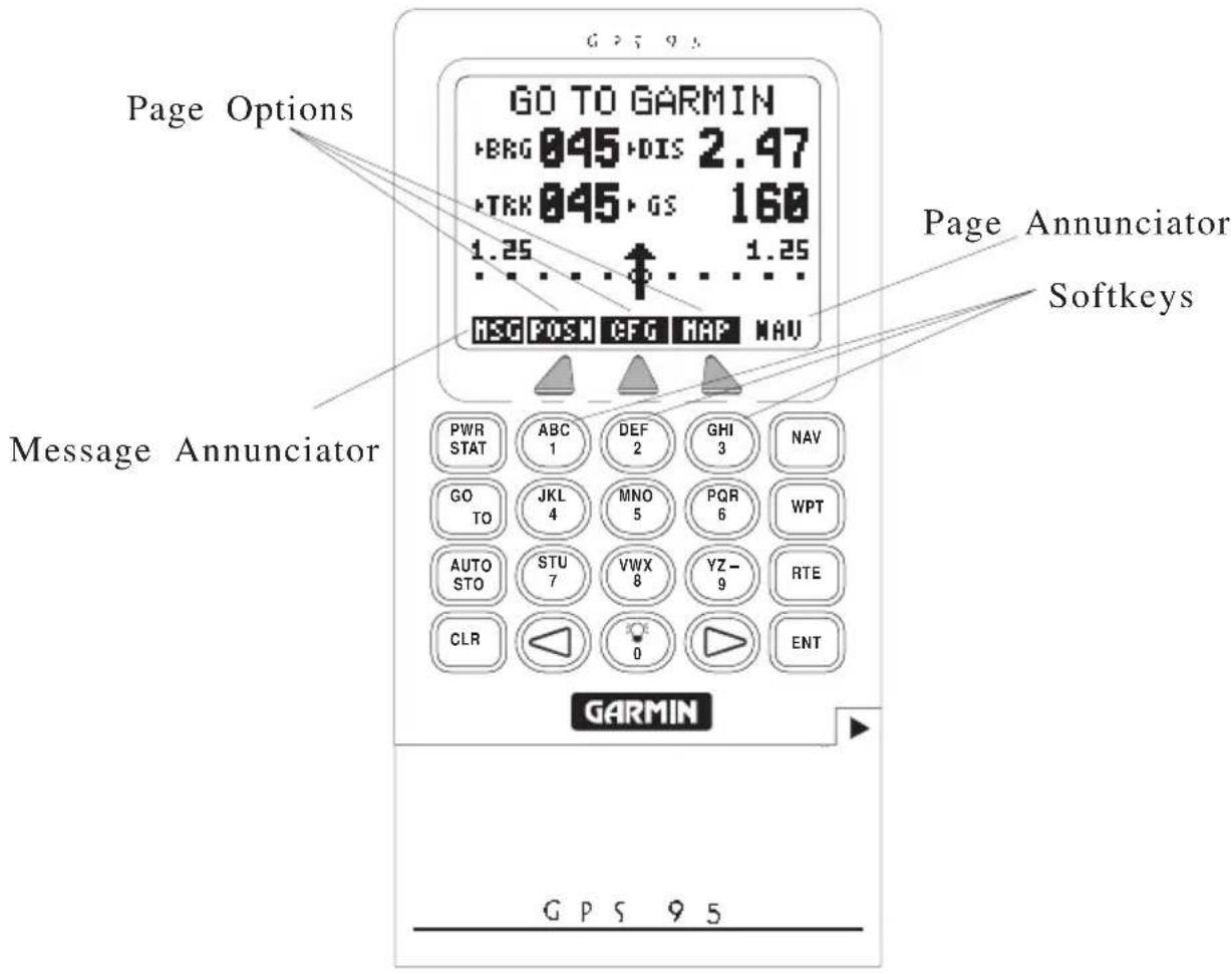
GO TO GARMIN BRG 045 DIS 2.47 TRK 045 GS 160 1.25 ↑ 1.25 MSG POSM CFG MAP NAV Page Options Page Annunciator Softkeys Message Annunciator PWR ABC DEF GHI NAV STAT 1 2 3 GO JKL MNO PQR WPT TO 4 5 6 AUTO STU VWX YZ- RTE STO 7 8 9 CLR 0 ENT GARMIN GPS 95The front panel consists of a 20-key keypad with a 85 x 64-pixel LCD display. Both the display and keypad may be illuminated for nighttime operation.
Information displayed on the LCD is commonly referred to as a “page.” The GPS 95 works with softkey operation. At the bottom of the screen is a list of page options. To select a different page, press the appropriate softkey below the desired option. Please note that the page options must be highlighted in order to use the softkeys. On the bottom line, extreme right, is the page annunciator which indicates the current page you are viewing.
2.3 CURSOR AND FIELDS
text_image
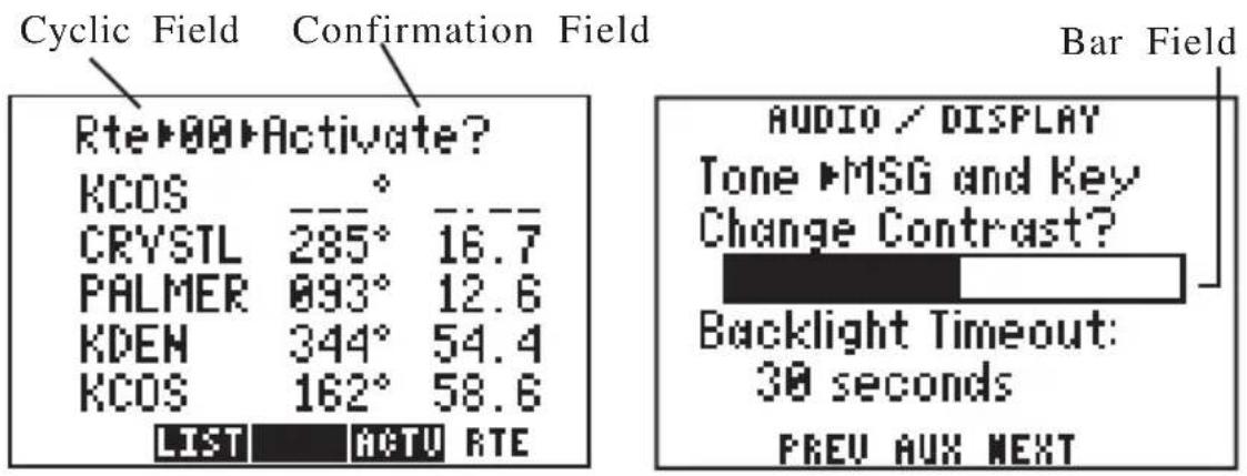
Cyclic Field Confirmation Field Rte▶00▶Activate? KCOS • CRYSTL 285° 16.7 PALMER 093° 12.6 KDEN 344° 54.4 KCOS 162° 58.6 LIST ACTU RTE Bar Field AUDIO / DISPLAY Tone ▶MSG and Key Change Contrast? Backlight Timeout: 30 seconds PREV AUX NEXTThe area of the page which is highlighted in reverse video is called the cursor. The cursor may be moved to locations on the page called fields which allow you to enter data or change options. You will encounter five types of fields.
- Numeric fields accept numbers only.
· Alphanumeric fields accept numbers as well as letters.
- Cyclic fields allow selection from several available options. A cyclic field is preceded by a prompt (▶). You may cycle through the choices by pushing CLR.
- Confirmation fields allow you to indicate your approval. For example, you will be asked to confirm that you want to delete a waypoint. Confirmation fields always end with a “?” character. Press ENT to approve the confirmation field.
- Bar fields allow an adjustable scale entry with the length of the bar representing the minimum to maximum setting. Use the arrow keys to make adjustments in bar fields.
The PWR/STAT key is a dual function key that controls unit power and system status. Pressing this when the unit is off will turn the unit on. To turn the unit off, press and hold PWR/STAT until the display is blank.
Pressing PWR/STAT momentarily while the unit is on will take you to the status pages. (See Chapter 8.) If the message annunciator is flashing and the tone sounds, you may push PWR/STAT to view the message.
GO TO
Pressing GOTO allows you to instantly define a destination waypoint and plot a course from present position to that destination. (See Chapter 4.)
AUTO STO
Pressing AUTOSTOre allows you to capture your present position instantaneously. (See Chapter 7.)
NAV
Pressing NAV allows you to view position and navigation information as well as the Map Page. (See Chapter 5.)
WPT
The WPT key allows you to view information about airports, NAVAIDs, intersections and user waypoints. The WPT key also allows you to create, edit, delete, and rename user waypoints. Further, you may view nearest waypoints or proximity waypoints. (See Chapter 3.)
RTE
The RTE key allows you to create, edit, review, activate, and delete routes. (See Chapter 6.)
Pressing either of the arrow keys allows you to move the cursor, scroll through information lists, and enter letters of the alphabet.
The alphanumeric keys allow you to enter letters and numbers. Use the arrow keys to select the desired letter or number from a given alphanumeric key.
Pressing this key while the cursor is not on a numeric or alphanumeric field allows you to change the backlight level. There are two backlighting levels.
Pressing CLR erases information in the cursor field. If the cursor is over a cyclic field, pressing CLR will toggle through several available options.
Pressing ENT confirms an entry or selection.


2.5 ENTERING DATA
You may enter data such as waypoint identifiers and user waypoint coordinates on certain pages. To enter data you must first move the cursor to the desired field by pressing the right or left arrow key. A data entry operation is completed by pressing the ENT key. If an error is made during the data entry process, press the CLR key to remove the erroneous character.
To enter a number...
- Press the key that is labeled with the desired number. The numbers will fill in from the right side of the field and move to the left as each new number is entered. For example, if you wish to enter “51” in a three space field, you must press the 5 and 1 keys in that order. You do not have to enter a leading zero. (Note: When entering numbers in an alphanumeric field press the key that is labeled with the desired number, then press the right or left arrow key twice.)
- Press CLR if you enter an incorrect number.
- Press ENT when you have filled all significant digits of the field with numbers.
To enter a letter...
- Press the key that is labeled with the desired letter.
- Press the right or left arrow key until the desired letter is displayed.
- Press CLR if you enter an incorrect letter.
- Press ENT when all the characters are entered.
The GPS 95 features a keypad feedback tone which will sound each time you press a key. If you enter data which is not appropriate for the field, the feedback tone will quickly sound three times indicating an error. The keypad feedback tone can be turned off if you wish. (See Section 8.10.)
2.6 VIEWING MESSAGES
From time to time, the GPS 95 will use a message to tell you of conditions needing attention. When the GPS 95 has a new message, the MSG annunciator will flash. When this occurs, press PWR/STAT to view the new message(s). Press PWR/STAT again to see the page you were viewing prior to reading the message. (See Appendix A for a complete list of GPS 95 messages.)
While the MSG annunciator is flashing, the GPS 95 will also generate a tone to alert you of the message. (If your unit is connected to an external alarm, it will also be activated.) Messages that demand immediate attention such as an arrival alarm generate a quick tone that will not stop until you view the message. All other messages generate a slow tone that will cease after 15 seconds. The message tone may be turned off if you wish. (See Section 8.10.)
Important messages will remain on the Message Page after being viewed. If this occurs, the MSG annunciator will be in view but will not flash. (If no messages exist, the MSG annunciator will not be visible.) To review these messages, press PWR/STAT to reveal the status menu options. Then press the key underneath the “AUX” page option. With the arrow keys, highlight “Messages” and press ENT.
2.7 TURNING THE GPS 95 ON
When the GPS 95 is turned on it will automatically perform internal checks to ensure proper operation, begin acquiring satellites, and once a sufficient number are received, display your present position. To see this power on sequence, take the GPS 95 outside to a location that is well away from buildings and other structures that might limit its view of the sky.
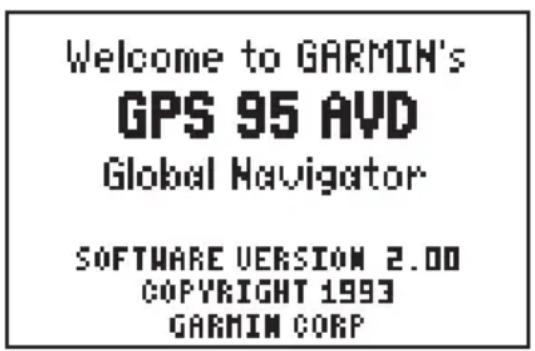
After you turn your GPS 95 on, it will conduct a series of self tests and display the following notice:
text_image
Welcome to GARMIN's GPS 95 AVD Global Navigator SOFTWARE VERSION 2.00 COPYRIGHT 1993 GARMIN CORP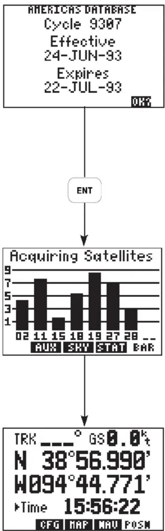
bar
| Time | Satellite Count | |---|---| | 02 | 4 | | 11 | 7 | | 15 | 2 | | 18 | 5 | | 19 | 9 | | 27 | 7 | | 28 | 3 | | — | — | | Category | Value | | :--- | :--- | | :--- | :--- | | AUX | 0 | | SKY | 0 | | STAT | 0 | | BAR | 0 | | Target | TRK (° GS0.0' t) | | :--- | :--- | | N | 38°56.990' | | W | 44.771' | | Time | 15:56:22 | CFG MAP MAU POSMFollowing completion of the tests, the Database Page will display the effective date, cycle and expiration date of the database. The GPS 95 will still function with an expired database; however, you must exercise extreme caution and always verify that the database information is correct before use. (WARNING: The accuracy of the data is assured only if current. Pilots using an out-of-date database do so entirely at their own risk.)
Press ENT to approve the Database Page.
The Satellite Bar Graph Page will be displayed, and the GPS 95 will begin acquiring satellites.
After a position is found (and if no keys have been pressed), the Position Page will be displayed and the unit is ready for normal operation. The process of satellite acquisition is fully automatic and, under normal circumstances, will take approximately 2-3 minutes to obtain navigation information. (If the unit has
been used in the past hour, it may take as little as 15 seconds.) If the GPS 95 has been moved a considerable distance since it was last used, additional time may be required as the unit performs an AutoLocate™. AutoLocate™ will automatically locate satellites and compute your position regardless of your location or where the unit was last used.
When four or more satellites with good geometry are available, the GPS 95 will automatically operate in the 3D mode in which latitude, longitude and altitude are computed. If only three satellites are available, the unit will operate in 2D mode in which only latitude and longitude are computed. When operating in the 2D mode, the unit will use the last computed altitude or your last entered altitude. (Section 5.4 describes how you may enter the altitude.)
Your GPS 95 will automatically update satellite orbital data as it operates. If you have not operated your unit for a period of six months or longer, it will take approximately 15 minutes to search the sky and collect new orbital data. You will be informed when your unit is searching the sky with the message "Searching the Sky." Once satellite orbital data is collected, it will be stored in memory. The memory is maintained by an internal battery, therefore the data will not be lost when you turn your GPS 95 off or remove the battery pack.
If the GPS 95 cannot acquire enough satellites for 2D or 3D navigation, you will be informed with the message “Poor GPS coverage”. If this situation occurs, make sure the antenna is properly connected and not obstructed by nearby buildings or other structures.
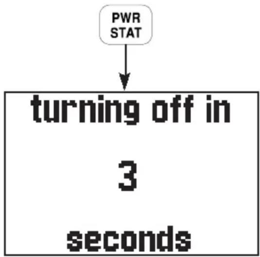
2.8 TURNING THE GPS 95 OFF
flowchart
graph TD
    A["PWR STAT"] --> B["turning off in\n3\nsolutions"]
To turn the GPS 95 off, press and hold the PWR/STAT key.
The Off Page will be displayed, the GPS 95 will perform a countdown and, after a brief delay, will shut off. All user waypoints, routes, and setup information that you have entered will be maintained while the unit is off - even if the battery pack is removed.
2.9 LEARNING TO USE THE GPS
95
If you are using the GPS 95 for the first time, you are encouraged to read Chapter 3 which introduces the GPS 95's waypoint and database features, Chapter 4 on the use of the GOTO key, and Chapter 5 for navigating to a waypoint. A sample trip is included in Chapter 5 to get you started on the use of the GOTO key and the various navigation pages available on your GPS 95. You may also want to read Chapter 8 on custom setups to configure the GPS 95 to your preferences. Afterward, you may want to read through the rest of this manual and make further use of the built-in simulator to practice with the advanced features.
CHAPTER 3
WAYPOINTS
The GPS 95 features a Jeppesen database providing Americas or International navigation information. (Refer to Section 1.2 for a specific description of information provided in the database.) The database contains information about waypoints. A basic waypoint consists of an identifier (up to six letters and/or numbers) and its location. You will have the opportunity to use waypoints extensively while operating the GPS 95. For example, you can build a route using waypoints, you can perform trip/fuel planning using waypoints, and you can even calculate the time of sunrise and sunset for a waypoint of interest.
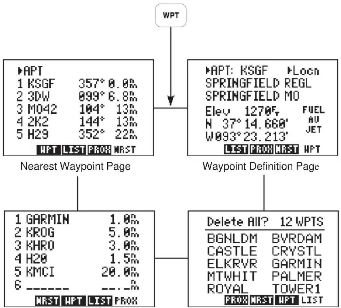
The GPS 95 features four primary waypoint pages. You may select the desired page by pressing WPT and, if needed, the appropriate softkey.
flowchart
graph TD
    A["WPT"] --> B["Nearest Waypoint Page"]
    A --> C["Waypoint Definition Page"]
    B --> D["1 GARMIN 1.0%"]
    B --> E["2 KROG 5.0%"]
    B --> F["3 KHRO 3.0%"]
    B --> G["4 H20 1.5%"]
    B --> H["5 KMCI 20.0%"]
    B --> I["6 ----"]
    C --> J["Delete All? 12 WPTS"]
    C --> K["BGNLDM BVRDAM"]
    C --> L["CASTLE CRYSTL"]
    C --> M["ELKRVR GARMIN"]
    C --> N["MTWHIT PALMER"]
    C --> O["ROYAL TOWER1"]
    C --> P["PROX NRST HPT LIST"]
Proximity Waypoint Page Waypoint List Page
3.1 WAYPOINT CATEGORIES
flowchart
graph TD
    A["AIRPORTS"] --> B["• Facility Name"]
    A --> C["• City/State"]
    A --> D["• Location"]
    A --> E["• Field Elevation"]
    A --> F["• Fuel Services"]
    A --> G["• Communication Frequencies"]
    A --> H["• Runways"]
    I["VORs"] --> J["—"]
    K["NDBs"] --> L["—"]
    M["INTERSECTIONS"] --> N["—"]
    O["USER DEFINED"] --> P["—"]
    Q["AIRPORT IDENT"] --> R["* Facility Name"]
    Q --> S["* City/State"]
    Q --> T["* Location"]
    Q --> U["* Field Elevation"]
    Q --> V["* Fuel Services"]
    Q --> W["* Communication Frequencies"]
    Q --> X["* Runways"]
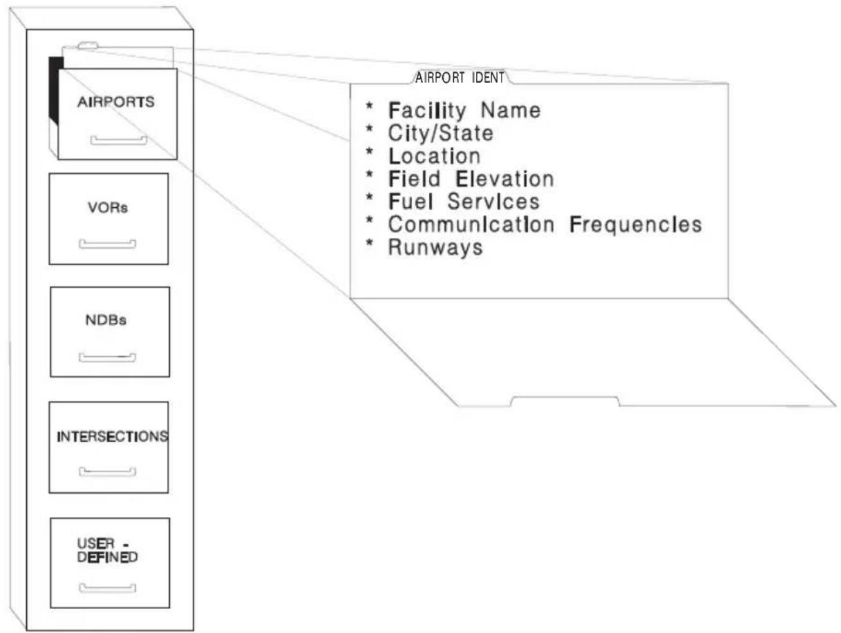
The GPS 95 organizes waypoints into one of five different categories: airports, VORs, NDBs, intersections and user waypoints. This organization is much like that of a file cabinet in which each drawer represents a different type of information. For example, the airport drawer contains information on airport locations, communication frequencies, runways, etc. In order to view the information stored in a given drawer, the drawer must be opened or selected. When using waypoints on the GPS 95 the “drawer”, or category, is selected on a cyclic field. The following sections describe procedures used to view information for each category of waypoint.
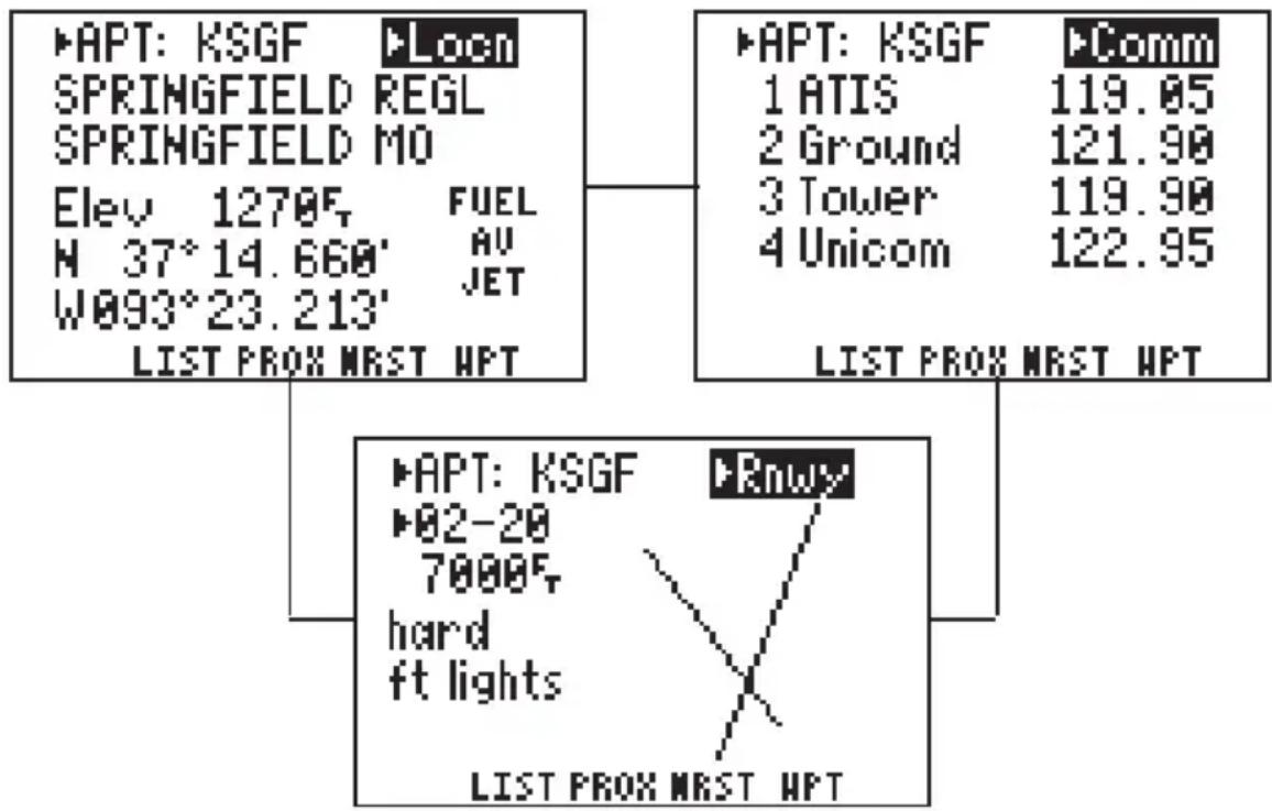
3.2 AIRPORT INFORMATION
flowchart
graph TD
    A["APT: KSGF"] --> B["SPRINGFIELD REGL"]
    A --> C["SPRINGFIELD MO"]
    A --> D["Elev 1270°, FUEL"]
    A --> E["H 37° 14.660' AU"]
    A --> F["W093°23.213' JET"]
    G["APT: KSGF"] --> H["1 ATIS 119.05"]
    G --> I["2 Ground 121.90"]
    G --> J["3 Tower 119.90"]
    G --> K["4 Unicom 122.95"]
    L["COMM"] --> M["LIST PROX NRST HPT"]
    N["APT: KSGF"] --> O["82-20 7000°, hard"]
    N --> P["ft lights"]
    Q["Rnwy"] --> R["LIST PROX NRST HPT"]
    style N stroke:#ff0000,stroke-width:2px
The GPS 95 features extensive information on airports:
- Identifier, facility name, city and state
- Position and elevation
· Fuel Services - Communication frequencies
- Runway information with graphic configuration
The airport information pages may be displayed from the Waypoint Definition Page.
To view airport information...
- Press WPT and, if needed, the WPT softkey to display the Waypoint Definition Page.
-
Notice the cyclic field in the upper left corner of the page. This field will indicate the category of waypoint that will be displayed. If “APT”, for airport, is not currently displayed: press the right arrow key, then press CLR (repeatedly) until “APT” is shown. (HINT: You may also select the waypoint category by pressing the corresponding alphanumeric key. In this case the “A” key, for airport.)
-
Press the right arrow key to move the cursor to the right of "APT".
- Enter the identifier of the desired airport using the alphanumeric and arrow keys. Press ENT. (Note: The airport identifiers in the GPS 95 database follow the standards set by the International Civil Aviation Organization [ICAO].)
- With “APT” selected, a second cyclic field will appear that allows you to view location (Locn), communication (Comm), or runway (Rnwy) information. Highlight this second field by pressing the right arrow key and press CLR to select the desired information page.
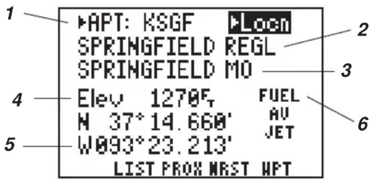
Airport Location Information
text_image
1 APT: KSGF LOCN SPRINGFIELD REGL SPRINGFIELD MO 2 3 4 Elev 1270F FUEL N 37°14.660' AV W093°23.213' JET 5 LIST PROX MRST HPT 6The airport location information includes the following
1) Airport identifier (selectable)
2) Airport facility name
3) City/state
4) Elevation (feet or meters)
5) Location
latitude/longitude -decimal degrees, degrees/decimal minutes, degrees/minutes/decimal seconds
grid systems -UTM/UPS, British grid, Irish grid
6) Fuel services available
· mo - Mogas
· av - 80/87 octane, 100LL, 100/130 octane
- jet - Jet A, Jet A-1 or Jet A+
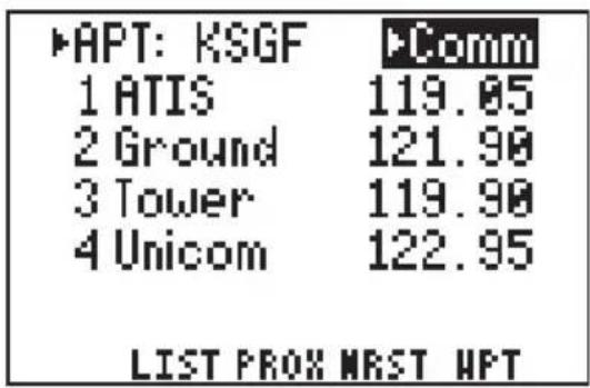
Airport Communication Information
text_image
APT: KSGF 1 ATIS 119.05 2 Ground 121.90 3 Tower 119.90 4 Unicom 122.95 LIST PROX NRST WPTThe airport communication information includes identifier (selectable), ATIS, ground, tower and unicom (or multicom) frequencies for the selected airport. Up to five communication frequencies may be displayed at a time. Additional frequencies may be viewed by scrolling.
To scroll through available frequencies...
- With the frequency information displayed, press the right arrow key repeatedly to view additional frequencies.
- To return to the beginning of the list, press the left arrow key repeatedly until the first frequency is displayed.
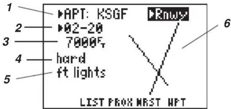
Airport Runway Information
text_image
1 ▶APT: KSGF ▶02-20 7000F hard ft lights 5 6 LIST FROM MRST HPTThe airport runway information includes the following:
1) Airport Identifier (selectable)
2) Runway designation (cyclic field)
3) Runway length (feet or meters)
4) Runway surface
- hard - Hard (asphalt, concrete, etc.)
- turf - Turf (grass)
- sealed - Sealed surface
- gravel - Gravel surface
- dirt - Dirt surface
- soft - Unknown soft surface
- unkwn - Unknown surface
- water - Water landing site
5) Lighting
- no lights - No runway lighting is available
· pc lights - Pilot controlled lighting with frequency - pt lights - Part time lighting
- ft lights - full time lighting
- unknown - Availability/type of lighting unknown
6) Graphic runway configuration, if available
The graphic runway configuration will display the layout of available runways. For the selected airport, information for each runway is available from the cyclic field for runway designation.
To view additional runway information...
- Using the arrow keys, place the cursor over the runway designation field.
- Press CLR to cycle through the available runways.
3.3 VOR INFORMATION
text_image
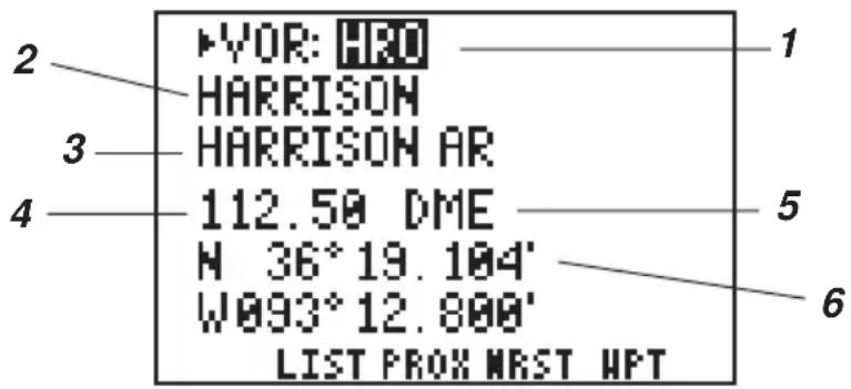
2 HYOR: HRO HARRISON HARRISON AR 112.50 DME M 36° 19.104' W093° 12.800' LIST PROX MRST HPT 1 3 4 5 6The GPS 95 also features considerable information on VORs:
1) Identifier (selectable)
2) Facility name
3) City/state
4) Frequency
5) DME indication, if applicable, for co-located DME or TACAN
6) Location (latitude/longitude or grid system)
You may select the desired VOR by two-to-three-character identifier, facility name or city/state. (See Section 3.10 for information on selecting VORs by facility name, or city/state.)
To select a VOR by identifier...
- Press WPT and, if needed, the WPT softkey to display the Waypoint Definition Page.
- If “VOR” is not currently displayed in the upper left corner: press the right arrow key to place the cursor on the cyclic field, then press CLR (repeatedly) until “VOR” is shown.
- Press the right arrow key to move the cursor to the right of "VOR".
- Enter the identifier of the desired VOR using the alphanumeric and arrow keys. Press ENT. The information for the selected VOR is displayed.
3.4 NDB INFORMATION
text_image
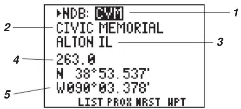
HDB: CIVI CIVIC MEMORIAL ALTON IL 263.0 M 38°53.537' W090°03.378' LIST PROX MRST HPT 1 2 3 4 5The GPS 95 displays the following information on NDBs:
1) Identifier (selectable)
2) Facility name
3) City/state
4) Frequency
5) Location (latitude/longitude or grid system)
You may select an NDB by its one-to-three-character identifier, facility name or city/state. (See Section 3.10 for information on selecting NDBs by facility name or city/state.)
To select an NDB by identifier...
- Press WPT and, if needed, the WPT softkey to display the Waypoint Definition Page.
- If “NDB” is not currently displayed in the upper left corner: press the right arrow key to place the cursor on the cyclic field, then press CLR (repeatedly) until “NDB” is shown.
- Press the right arrow key to move the cursor to the right of "NDB".
- Enter the identifier of the desired NDB using the alphanumeric and arrow keys. Press ENT. The information for the selected NDB is displayed.
3.5 INTERSECTION INFORMATION
text_image
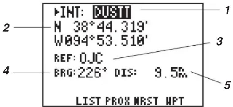
INT: DUSTT H 38°44.319' W094°53.510' REF: OJC BRG: 226° DIS: 9.5Ω LIST PROX MRST WPTThe GPS 95 features the following information on intersections:
1) Identifier (selectable)
2) Location (latitude/longitude or grid system)
3) Reference waypoint identifier
4) Bearing from reference waypoint to selected intersection
5) Distance from reference waypoint to selected intersection
Intersections are only selected by identifier. Once an intersection is selected, the identifier of, bearing from, and distance from the nearest VOR will be displayed. (NOTE: The VOR is simply the nearest facility and is not necessarily the VOR used to define the intersection.)
To select an Intersection...
- Press WPT and, if needed, the WPT softkey to display the Waypoint Definition Page.
- If “INT” for intersection, is not currently displayed in the upper corner: press the right arrow key to place the cursor on the cyclic field, then press CLR (repeatedly) until “INT” is shown.
- Press the right arrow key to move the cursor to the right of "INT".
- Enter the identifier of the desired intersection using the alphanumeric and arrow keys. Press ENT. The information for the selected intersection is displayed.
3.6 USER WAYPOINT INFORMATION
text_image
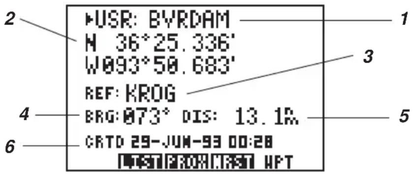
2 •USR: BYRDAM M 36°25.336' W093°50.683' REF: KROG 4 ERG:073° DIS: 13.1% 6 CRTD 29-JUN-93 00:28 HPT 1 3 5In addition to the airport, VOR, NDB and intersection information that is already stored in your GPS 95, you may enter an additional 500 locations as user waypoints.
The GPS 95 will display the following user waypoint information:
1) Waypoint identifier
2) Location (latitude/longitude or grid system)
3) Reference waypoint identifier
4) Bearing from reference waypoint to selected user waypoint
5) Distance from reference waypoint to selected user waypoint
6) User comments
User waypoints are only selected by the identifier that you assign.
To select a user waypoint...
- Press WPT and, if needed, the WPT softkey to display the Waypoint Definition Page.
- If “USR”, for user waypoint, is not currently displayed in the upper corner: press the right arrow key to place the cursor on the cyclic field, then press CLR (repeatedly) until “USR” is shown.
- Press the right arrow key to move the cursor to the right of "USR".
- Enter the identifier of the desired user waypoint using the alphanumeric and arrow keys. Press ENT. The information for the selected user waypoint is displayed.
You may select a reference waypoint by moving the cursor to the reference waypoint identifier field and entering the desired waypoint identifier (airport, VOR, NDB, intersection or user waypoint).
3.7 CREATING USER WAYPOINTS
text_image
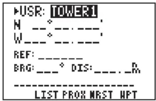
▶USR: TOWER1 H _°_ : _ W _°_ : _ REF: _ _ BRG: _° DIS: _ . _R ----LIST PROX MRST HPTWhen a waypoint identifier has been entered that does not exist in memory the GPS 95 will assume you wish to create a new waypoint. You may create a new waypoint using one of two methods: direct position entry (latitude/longitude or grid system) or relative to an existing waypoint.
In order to create a waypoint by direct position entry the coordinates for the new waypoint must be known and entered directly into the unit.
To enter the waypoint position directly...
- With the Waypoint Definition Page displayed (and user waypoint information shown), press the right arrow until the cursor is over the waypoint identifier field.
- Enter the identifier of the new waypoint using the alphanumeric and arrow keys. Press ENT when complete. The cursor will move to the position coordinates.
- Enter the position of the new waypoint. Press ENT after data is entered into each field. The number of fields required for position entry will depend on the position coordinate option selected. (See Section 8.7.) If latitude and longitude coordinates are selected there will be four fields if decimal degrees are used - two to define the hemispheres ("N" or "S", "E" or "W") and two to enter the latitude and longitude degrees. If latitude and longitude coordinates are selected with degrees, minutes and decimal seconds, there will be eight data entry fields to define the position since degrees, minutes and seconds are each divided into their own field. If a grid system is selected it will have a different number of fields depending on the format of the selected grid.
A new waypoint can be defined relative to another waypoint already contained within the GPS 95's memory. When creating a new waypoint relative to an existing waypoint, you will define a distance and bearing from the existing waypoint to the new waypoint location.
To create a waypoint offset from a reference waypoint...
- With the Waypoint Definition Page displayed (and user waypoint information shown), press the right arrow until the cursor is over the waypoint identifier field.
- Enter the identifier of the new waypoint using the alphanumeric and arrow keys. Press ENT when complete.
- Press the right arrow key until the cursor is over the reference waypoint identifier field.
- Enter the identifier of the desired reference waypoint (airport, VOR, NDB, intersection or user waypoint) and press ENT.
- Enter the bearing from the reference waypoint to the new waypoint and press ENT. The bearing will be true or magnetic depending on the unit setups. (See Section 8.7.)
- Enter the distance from the reference waypoint to the new waypoint and press ENT. The distance will be in nautical miles, statute miles or kilometers depending on the unit setups. (See Section 8.7.)
Once the waypoint location is created, the user comment field will automatically
be filled with the date and time the waypoint was created. You may enter a different user comment by placing the cursor over this field and entering the new comment with the alphanumeric and arrow keys, followed by ENT when complete.
You may also modify the position of an existing user waypoint from the Waypoint Definition Page. A user waypoint may be changed using the same procedures described above for creating a user waypoint, by direct position entry (latitude/longitude or grid system) or relative to an existing waypoint. When modifying an existing waypoint, the new position data is entered directly over the old data. For a given data field, once the ENT key is pressed the position data is updated. (NOTE: If a waypoint is being used for navigation, its position cannot be modified. An attempt to modify the position of such a waypoint will result in the message “Cannot change active waypoint”.)
3.8 WAYPOINT LIST
text_image
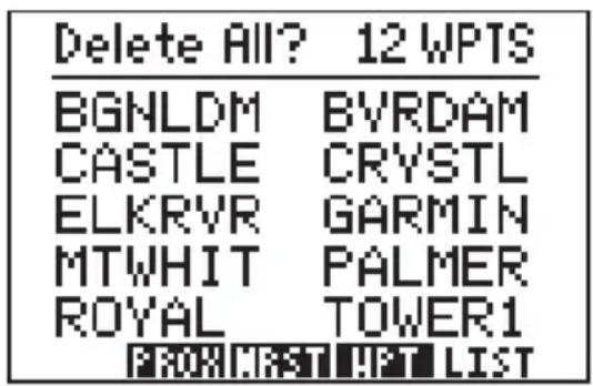
Delete All? 12 WPTS BGNLDM BVRDAM CASTLE CRYSTL ELKRVR GARMIN MTWHIT PALMER ROYAL TOWER1 FROM FIRST LISTThe Waypoint List Page allows you to view all stored user waypoints in your GPS 95. The list may be scrolled, with the arrow keys, to view all the waypoints. From this page, waypoints may be selected for deletion, renaming or to activate a GOTO. (See Chapter 4 for information on the GOTO function.)
To delete a user waypoint...
- Select the Waypoint List Page by pressing WPT and the LIST softkey, if needed.
- With the arrow keys, place the cursor on the desired waypoint.
- Press CLR and ENT.
- A confirmation page is displayed. Press ENT to confirm or CLR to cancel.
NOTE: If you attempt to delete a proximity or route waypoint, a message will be displayed. You must delete the proximity alarm or the route before you can delete the waypoint. (See Sections 3.12 and 6.5.)
The Waypoint List Page also gives you the option of deleting all user waypoints at one time.
To delete all user waypoints...
- Select the Waypoint List Page by pressing WPT and the LIST softkey, if needed.
- With the arrow keys, place the cursor over "Delete ALL?" and press ENT.
- A confirmation page is displayed. Press ENT to confirm the deletion of all waypoints or CLR to cancel.
NOTE: The “Delete All?” selection will delete all routes and proximity waypoints as well.
From the Waypoint List Page you may also change the name of any user waypoint.
To rename a user waypoint...
- Select the Waypoint List Page by pressing WPT and the LIST softkey, if needed.
- With the arrow keys, place the cursor on the desired waypoint.
- Type in a new name for the waypoint and press ENT.
- A confirmation page is displayed. Press ENT to confirm the name change or CLR to cancel.
3.9 USING WAYPOINTS
You may use waypoints on many GPS 95 pages. A waypoint is selected by entering its identifier and pressing ENT. Some waypoints in the database may have the same identifier. When you have entered a waypoint name that is not unique, the Duplicate Waypoint Page will be displayed for you to select the desired waypoint.
text_image
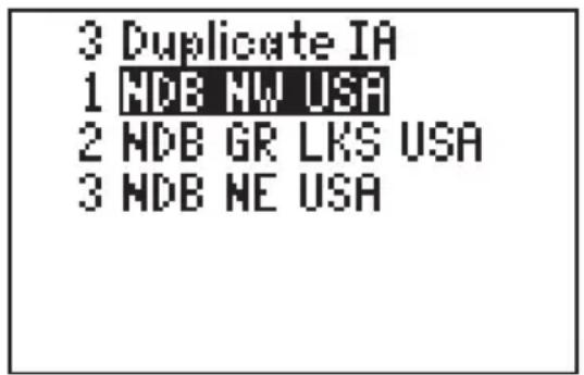
3 Duplicate IA 1 NDB NW USA 2 NDB GR LKS USA 3 NDB NE USAThe waypoint identifier and number of duplicates are displayed on the first line of the Duplicate Waypoint Page. On the following lines, the waypoint type and region for each duplicate waypoint is displayed, sorted by distance from present position. From this list you may select the desired waypoint by placing the cursor on the desired waypoint, using the arrow keys, and pressing ENT.
3.10 USING WAYPOINTS BY SCANNING
The GPS 95 offers a waypoint scanning feature which will simplify waypoint entry. Airports, VORs and NDBs may be scanned by identifier, city or facility name. Intersections and user waypoints can only be scanned by identifier.
flowchart
graph LR
A["▶APT: KT"] --> B["->"]
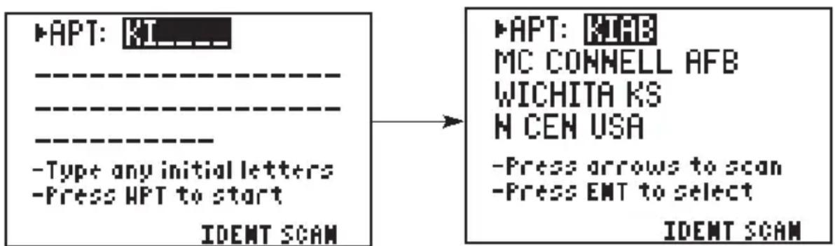
C["-Type any initial letters<br>-Press HPT to start<br>IDENT SCAN"] --> B
D["▶APT: KIFB<br>MC CONNELL AFB<br>WICHITA KS<br>N CEN USA<br>-Press arrows to scan<br>-Press ENT to select<br>IDENT SCAN"] --> B
To select a waypoint by scanning identifiers...
- On a blank waypoint identifier field press the WPT key. (If the identifier field is not blank, press CLR first.) The Scan Page will be displayed and the cursor will be on a cyclic field.
- Select the desired waypoint category (airport, VOR, NDB, intersection or user) by pressing CLR (repeatedly).
- Press the right arrow key once to place the cursor on the waypoint identifier field.
- Enter the starting letter, or letters, of the waypoint identifier. You may limit the scan to the level that you desire. For example, if you enter "K" the GPS 95 will scan through all waypoints (for the selected category) that begin with the letter "K"; but, if you enter "KIA" the GPS 95 will display only those waypoints that begin with "KIA".
- Press WPT to begin scanning.
- Press the right arrow key to sequence through the available waypoints. If you pass the desired waypoint, you may press the left arrow key to scan backwards through the list.
- Once the desired waypoint is selected, press ENT to accept the waypoint and complete the scan. The GPS 95 will revert to the page that you were on prior to scanning. The selected waypoint will be displayed on the waypoint identifier field.
To select a waypoint by scanning city names...
- On a blank waypoint identifier field press the WPT key. (If the identifier field is not blank, press CLR first.) The Scan Page will be displayed and the cursor will be on a cyclic field.
- Select the desired waypoint category (airport, VOR or NDB only) by pressing CLR (repeatedly).
- Press the right arrow key three times to place the cursor on the city/state field.
- Enter the starting letter, or letters, of the desired city. You may limit the scan to the desired level by designating the number of starting letters (as described above when scanning by identifier). There is no need to designate the state. Once the scan begins the appropriate state will be displayed automatically.
- Press WPT to begin scanning.
- Press the right arrow key to sequence through the available waypoints. If you pass the desired waypoint, you may press the left arrow key to scan backwards through the list.
- Once the desired waypoint is selected, press ENT to accept the waypoint and complete the scan. The GPS 95 will revert to the page that you were on prior to scanning. The selected waypoint will be displayed on the waypoint identifier field.
To select a waypoint by scanning facility names...
- On a blank waypoint identifier field press the WPT key. (If the identifier field is not blank, press CLR first.) The Scan Page will be displayed and the cursor will be on a cyclic field.
- Select the desired waypoint category (airport, VOR or NDB only) by pressing CLR (repeatedly).
- Press the right arrow key twice to place the cursor on the facility name.
- Enter the starting letter, or letters, of the facility name. You may limit the scan to the desired level by designating the number of starting letters (as described previously when scanning by identifier).
- Press WPT to begin scanning.
- Press the right arrow key to sequence through the available waypoints. If you pass the desired waypoint, you may press the left arrow key to scan backwards through the list.
- Once the desired waypoint is selected, press ENT to accept the waypoint and complete the scan. The GPS 95 will revert to the page that you were on prior to scanning. The selected waypoint will be displayed on the waypoint identifier field.
NOTE: When duplicate entries exist for the selected item (identifier/city/facility name), the additional entries may be viewed by continuing to press the arrow keys until the desired waypoint is selected.
3.11 REVIEWING WAYPOINTS
The GPS 95 allows you to quickly review waypoint information without entering the waypoint identifier. For example, you may review information regarding the waypoints in a route, or review the definition of the nearest waypoints. In general, if the cursor is over a waypoint identifier, you may quickly review the information about that waypoint.
text_image
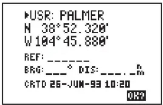
▶USR: PALMER N 38°52.320' W 104°45.880' REF: ________ BRG: ______° DIS: _______._m CRTD 26-JUN-93 10:20 OK?To review a waypoint definition...
- Place the cursor over a waypoint identifier (using the arrow keys) and press ENT. The Waypoint Definition Page is displayed indicating the category of waypoint shown.
- If the waypoint is an airport, a second cyclic field will appear in the upper right corner of the page. You may select between location (Locn), communication (Comm) or runway (Rnwy) information by highlighting this cyclic field and pressing CLR until the desired information is displayed.
- With the cursor over “OK?”, press ENT to exit the review process and return to the previous page.
3.12 PROXIMITY ALARM WAYPOINTS
text_image
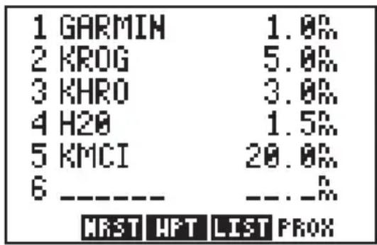
1 GARMIN 1.0% 2 KROG 5.0% 3 KHRO 3.0% 4 H20 1.5% 5 KMCI 20.0% 6 ---- ---- HRST WFT LIST PROXThe Proximity Waypoint Page allows you to define an alarm circle around a waypoint. This feature is useful in defining an area around a TCA (Class B), MOA, tower, etc. When you approach one of these waypoints the GPS 95 will notify you with an alarm tone and the message, “Prox Alarm - [waypoint name],” if you enter the alarm circle.
The GPS 95 allows you to define a maximum of nine proximity waypoints. Scroll through the proximity waypoint list using the arrow keys.
To set a proximity waypoint...
- Select the Proximity Waypoint Page by pressing WPT and the PROX softkey, if needed.
- Place the cursor on a blank waypoint identifier field using the arrow keys.
- Enter the identifier of the desired waypoint and press ENT. (NOTE: If neither the waypoint name nor the location exists in memory, the Waypoint Definition Page will be displayed. You must then enter the waypoint location.)
- Enter the proximity alarm distance and press ENT. The proximity alarm distance defines a radius from the waypoint.
If the newly created proximity alarm circle overlaps with an existing proximity alarm circle, you will be informed of the overlap with the message “Proximity Overlap”. As long as the overlap remains this message will be displayed each time the GPS 95 is turned on. (WARNING: If you enter the overlap area the unit will only inform you of the nearest waypoint.)
3.13 NEAREST WAYPOINTS
text_image
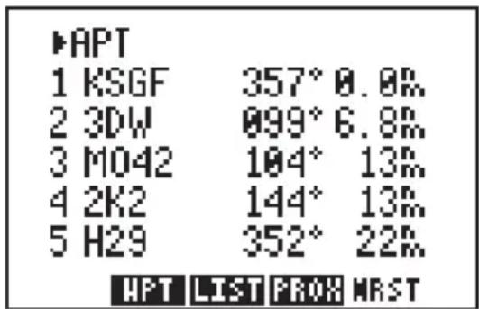
▶APT 1 KSGF 357° 0.0% 2 3DW 099° 6.8% 3 M042 104° 13% 4 2K2 144° 13% 5 H29 352° 22% HPT LIST PROH MRSTAn important feature on the GPS 95 is the ability to display up to nine nearest waypoints (of each category) within 200 nautical miles of your present position. The bearing and distance to each nearest waypoint is also displayed. The nearest waypoint feature can be critical in finding a safe landing location in the event of an in-flight emergency.
To view nearest waypoint information...
- Select the Nearest Waypoint Page by pressing WPT and the NRST softkey, if needed.
- Place the cursor key on the cyclic field in the upper left of the page using the arrow keys.
- Select the desired waypoint category by pressing CLR. The five nearest waypoints for that category will be displayed, along with the bearing and distance to each.
- Use the arrow keys to scroll through the list and view additional nearest waypoints (up to nine).
Keep in mind that you may view additional information for any nearest waypoint by placing the cursor on the waypoint identifier and pressing ENT. In the case of a nearest airport; facility name, elevation, fuel services, communication frequencies, and runway information are all instantly available. (See Section 3.11.)
The nearest waypoint feature can be used in conjunction with the GOTO key to provide instantaneous navigation information to a nearby waypoint. Simply place the cursor over the desired nearest waypoint identifier and press GOTO, followed by ENT. The GPS 95 will immediately plot a course from your present position to the nearby waypoint. (See Chapter 4 for more information on the GOTO key.)
CHAPTER 4
GETTING THERE FAST - GOTO
The GOTO function allows you to quickly set a course from your position to any waypoint.
text_image
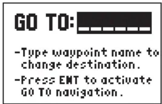
GO TO: -Type waypoint name to change destination. -Press EMT to activate GO TO navigation.To activate the GOTO function...
- Press GOTO. The GOTO Page will be displayed with the cursor on the GOTO waypoint field. If the GPS 95 is currently navigating to a waypoint, that waypoint will be offered as the default GOTO waypoint. If the waypoint field is blank or the waypoint shown is not the desired destination, type the new name right over the old name. NOTE: If a non-existent waypoint name is entered, the GPS 95 will assume that this is a new user waypoint and will display a blank Waypoint Definition Page where you may enter the new waypoint's coordinates.
- Confirm the GOTO waypoint by pressing ENT. The Navigation Summary Page will be displayed with the D-bar on the CDI centered. (See Section 5.1 for more information on the Navigation Summary Page and the CDI.)
You may also select the desired GOTO waypoint identifier by scanning. If the desired waypoint is an airport, VOR or NDB; you may scan by city or facility name (as well as identifier) to select the desired GOTO waypoint identifier. (See Section 3.10 for more information on waypoint scanning.)
Alternatively, the GOTO function may be quickly activated from any page (e.g., the Nearest Waypoint Page or the Waypoint List Page) by placing the cursor over the desired waypoint name and pressing GOTO. The GOTO Page will be displayed with the cursor on the GOTO waypoint name. The GOTO function will be activated when the ENT key is pressed.
You may cancel the GOTO function at any time.
To cancel the GOTO function...
- Press GOTO. The GOTO Page will be displayed.
- Press CLR. The GOTO waypoint name will become blank.
- Press ENT. The GPS 95 will start to navigate using the active route, if it has been programmed. (See Chapter 6.) Otherwise, the GPS 95 will stop computing waypoint navigation data.
CHAPTER 5
NAVIGATION INFORMATION
The GPS 95 features four navigation pages. You may select the desired page by pressing NAV and, if needed, the appropriate softkey.
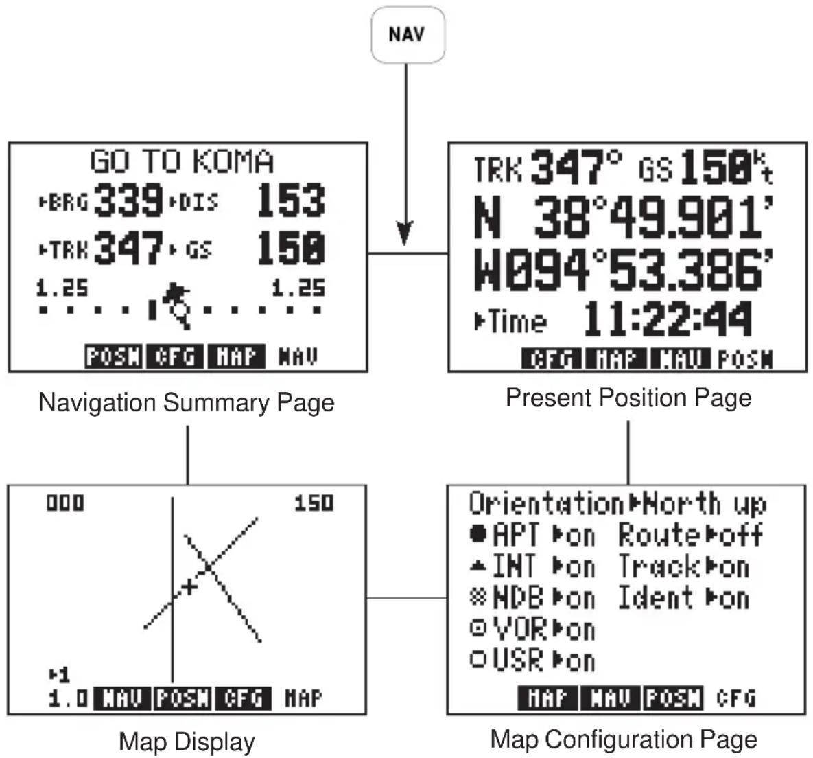
flowchart
graph TD
    A["NAV"] --> B["GO TO KOMA<br>• BRG 339 • DIS 153<br>• TRK 347 • GS 158<br>1.25 ... 1.25<br>POSM CFG MAP NAV"]
    B --> C["TRK 347° GS 158*<br>N 38°49.901'<br>W094°53.386'<br>• Time 11:22:44<br>CFG MAP MAP POSM"]
    C --> D["Present Position Page"]
    D --> E["Orientation▶North up<br>● APT ▶ on Route▶off<br>▲ INT ▶ on Track▶on<br>※ MDB ▶ on Ident ▶ on<br>○ VOR ▶ on<br>○ USR ▶ on<br>MAP MAP POSM CFG"]
    E --> F["Map Display"]
    F --> G["000 150<br>1.0 MAU POSM CFG MAP"]
    G --> H["Navigation Summary Page"]
    H --> I["Map Configuration Page"]
5.1 NAVIGATION SUMMARY PAGE
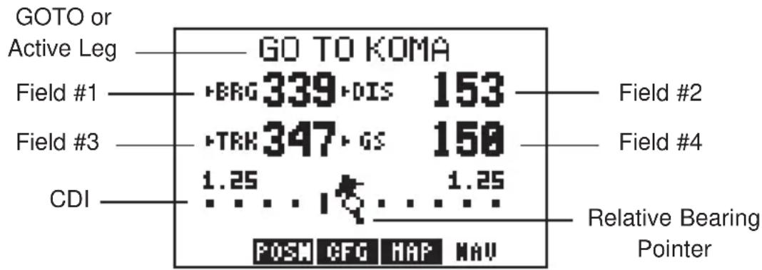
text_image
GOTO or Active Leg GO TO KOMA Field #1 BRG 339 DIS 153 Field #2 Field #3 TRK 347 GS 158 Field #4 CDI 1.25 ... 1.25 POSW CFG HAP NAV Relative Bearing PointerThe Navigation Summary Page displays direction, distance and speed information to guide you along a route or to a GOTO destination. Included is a graphic course deviation indicator (CDI), at the bottom of the page, which illustrates your position relative to the course. The current CDI scale setting is shown at each end of the CDI scale. (See Section 8.8 for information on setting the CDI scale.) A relative bearing pointer at the center of the CDI indicates the bearing to the waypoint relative to the current ground track (TRK). In the example shown, the current ground track is 347 degrees and the bearing to our destination is 339 degrees. The relative bearing pointer points slightly to the left indicating that our destination is ahead, but slightly to the left of our current direction of travel.
At the top of the Navigation Summary Page the current GOTO destination is displayed, or the “active leg” of a route when using the GPS 95’s route navigation features. (See Chapter 6 for information on route navigation.) During the process of acquiring satellites, the GPS 95 will not provide navigation data. The top line of the Navigation Summary Page will indicate this condition, as illustrated below.
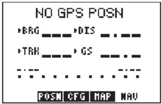
text_image
NO GPS POSN BRG ---- +DIS -------------- TRH ---- +GS -------------- POSN CFG MAP NAVIf the GPS 95 has acquired satellites, but is not navigating to a waypoint (i.e., no GOTO destination or route has been activated), the top line of the Navigation Summary Page will indicate that no destination has been defined, as illustrated below.
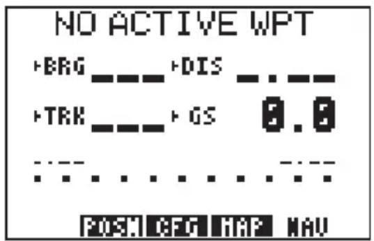
text_image
NO ACTIVE WPT +BRG ---- +DIS ---- +TRK ---- +GS 0.0 ............ POST CFG MAP NAVNotice that the Navigation Summary Page has four cyclic fields. With these cyclic fields you may configure your GPS 95 to display navigation information according to your preferences. (See Appendix B for a description of navigation terms.) The field options are as follows:
Field #1 (top left)
· Bearing to destination waypoint (BRG)
· Course to steer (CTS)
- Desired track (DTK)
· Ground track (TRK)
- Off course error, or turn angle (TRN)
Field #2 (top right)
· Distance to destination waypoint (DIS)
· Cross track error (XTK)
· VNAV altitude (V)
Field #3 (bottom left)
· Ground track (TRK)
- Ground speed (GS)
Field #3 (bottom right)
- Ground speed (GS)
· Estimated time of arrival (ETA)
· Estimated time enroute (ETE)
5.2 MAP DISPLAY
text_image
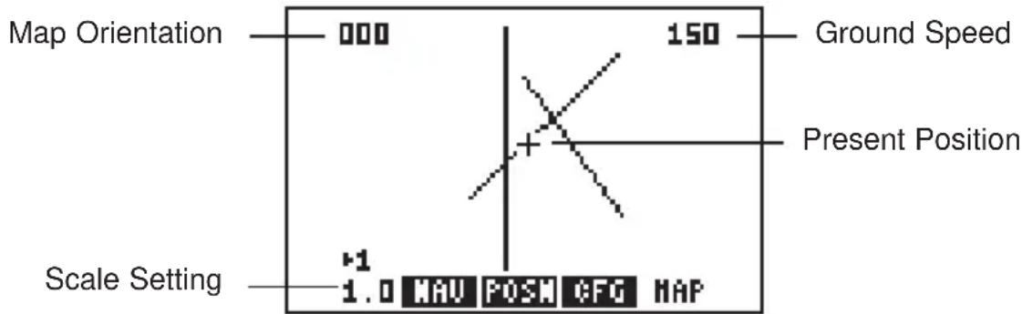
Map Orientation 000 150 Ground Speed Present Position Scale Setting +1 1.0 MAU POSM CFG MAPThe GPS 95 also features a Map Display which shows a graphic top view of your location. The current ground speed is indicated at the top right corner of the display. The top left corner defines the orientation of the Map Display: "North up", "Ground track up", or "Desired track up." If "000" is shown, the Map Display is oriented "North up." (See Section 5.3 for selection of Map Display orientation.) Your present position is shown in the middle of the display. If the Map Display is oriented "Ground track up" your present position is indicated by an aircraft symbol. If either "North up" or "Desired track up" orientations are selected, the present position is indicated by a crosshair ("+").
text_image
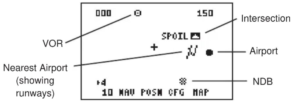
000 150 Intersection VOR SPOIL + Airport Nearest Airport (showing runways) NDB 10 MAV POSM CFG MAPYou may select which items you wish to display. The Map Display can provide the fifteen nearest waypoints of each category: airport, VOR, NDB, intersection, and user. GOTO or route waypoints which are not part of the fifteen nearest waypoints will also be displayed. The track history and/or the active route may also be shown as solid lines on the display. Selection of which items to display is performed on the Map Configuration Page. (See Section 5.3.)
You may view the identifier for any waypoint on the Map Display by moving the cursor over that waypoint (with the arrow keys). By moving the cursor around the page you can identify each waypoint shown. Keep in mind that when the cursor is over a waypoint identifier you may review information about that waypoint by pressing ENT, or plot a course to that waypoint by pressing GOTO. (HINT: When viewing waypoint information you may quickly return the cursor to the lower left corner by pressing CLR.)
The scale distance for the screen (distance represented by the height of the screen) is at the lower left corner of the screen. The scale number (directly above the scale distance) may be changed to the level that you desire. You may zoom in to a .5 nautical mile scale, or out to a maximum scale of 240 nautical miles.
To set the Map Display scale...
- Press the left arrow key to place the cursor on the scale number.
- Press CLR to sequence through the available scale settings. (HINT: The scale setting may also be selected by pressing the alphanumeric key that corresponds to the desired scale.)
5.3 MAP CONFIGURATION
text_image
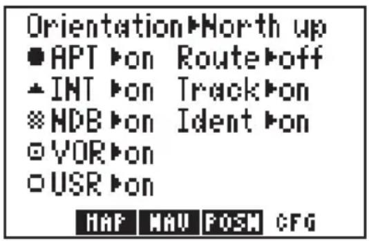
Orientation►North up ● APT ►on Route►off ▲ INT ►on Track►on ※ HDB ►on Ident ►on ○ VOR ►on ○ USR ►on HAP NAV POSM CFGThe Map Configuration Page allows you to tailor the GPS 95's Map Display to your preferences. As previously stated, the Map Display can show airports, NAVAIDs, user waypoints, the active route, your track history and/or waypoint identifiers. Any of these items may be turned on or off according to your preferences. For example, when the Map Display is zoomed out to its maximum levels the screen may appear too cluttered to be easily read. In this case, you could turn off the information not needed to create a more legible display.
To turn display information on/off...
- Press NAV and CFG softkey, if needed, to select the Map Configuration Page.
- Place the cursor on the desired item using the arrow keys.
- Press CLR to toggle between "on" and "off".
- If you wish to return to the Map Display: place the cursor on the menu bar using the arrow keys, then press the MAP softkey.
The Map Display orientation is also selected from the Map Configuration Page. The Map Display may be oriented as follows:
- North up - The Map Display will always be displayed with north as the top of the page.
- TRK up - Track up. The Map Display will be oriented such that your current ground track direction is at the top of the page.
- DTK up - Desired track up. The Map Display will be oriented along the course between the “active from” and “active to” waypoints.
5.4 PRESENT POSITION

text_image
TRK 347° GS 150° N 38°49.901' W094°53.386' ▶Time 11:22:44 CFG MAP MAU POSMAs mentioned earlier, the Present Position Page is automatically displayed when the GPS 95 is turned on and a position is obtained. The top line of this page displays your ground track (TRK) and ground speed (GS). The next two lines indicate your current position according to the coordinate format and map datum selected. In the example shown above, the position is displayed in degrees and decimal minutes of latitude/longitude. (See Section 8.3 for more information on coordinate format selections and Section 8.8 for more information on map datum selections.)
The bottom line of the Present Position Page is a cyclic field which can display either altitude above mean sea level (MSL) or current time (UTC or local). Select the desired option by placing the cursor on this field and pressing CLR.
When the GPS 95 is performing 2D navigation, the last known altitude will be used to calculate a present position. If the altitude is not accurate within a few hundred feet you should manually enter your altitude.
To enter the altitude (2D only)...
- Use the arrow keys to place the cursor to the right of "Altitude".
- Enter the correct altitude and press ENT.
During the initial satellite acquisition, the displayed position is the last known position stored in the GPS 95. If your position has moved a considerable distance since the unit was last used, the GPS will perform an AutoLocate ^™ (See Section 2.7.) This process can take up to ten minutes as the GPS 95 determines its new location. Alternatively, you may enter a more accurate initial position directly on the Present Position Page to speed up the acquisition process. (You may also change the position at any time while you are in simulator mode.)
5.5 SAMPLE TRIP
Your new GPS 95 is really very simple to operate. For the purpose of this demonstration is assumed that the factory default settings, including the selection of nautical units (knots, nautical miles, feet), have not been changed. If these settings have been changed, the unit may display different data than that presented here. (See Chapter 8 on unit setups.)
flowchart
graph TD
    A["Welcome to GARMIN's GPS 95 AVD\nGlobal Navigator"] --> B["SOFTWARE VERSION 2.00\nCOPYRIGHT 1993\nGARMIN CORP"]
    B --> C["AMERICAS DATABASE\nCycle 9307\nEffective\n24-JUN-93\nExpires\n22-JUL-93"]
    C --> D["ENT"]
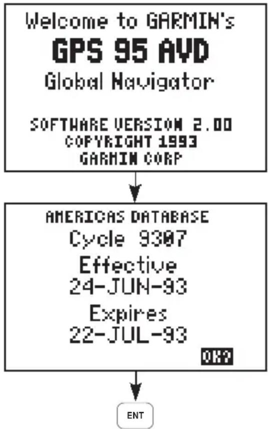
Turn the GPS 95 on. The unit will display the welcome screen and perform several diagnostic checks to ensure that proper operation will occur.
The Database Page will be displayed showing the cycle, effective date and expiration date of the database. Review the database information and press ENT to approve the information.
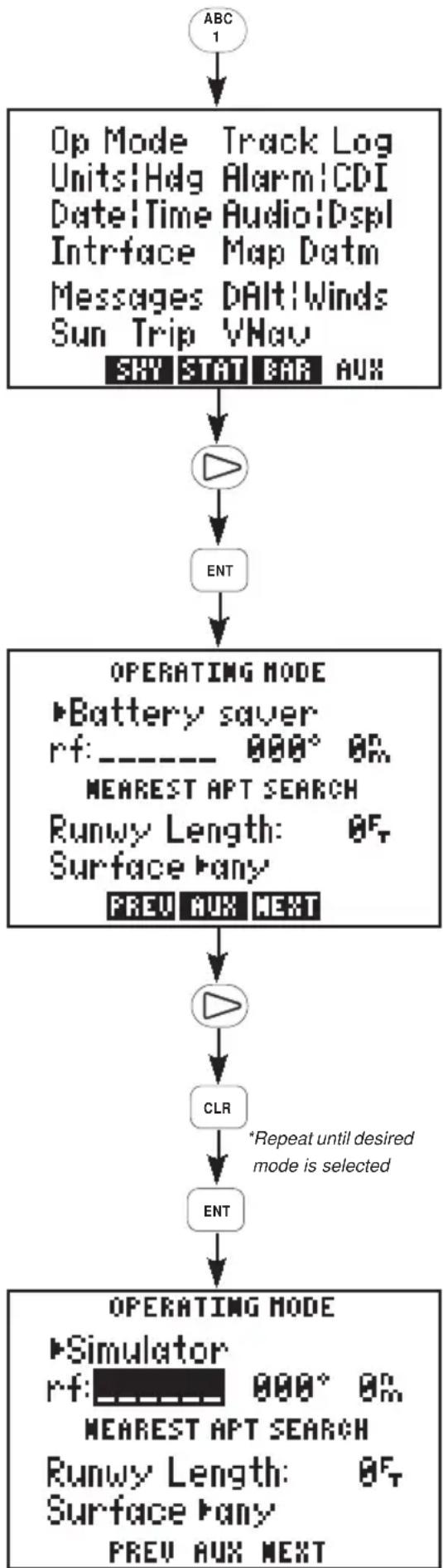
Since this is a simulated trip, you will select the simulator mode and indicate a starting location for the trip. Your simulated trip will begin at an intersection called LENEX in Lenexa, Kansas. (NOTE: This sample trip assumes that the Americas database is used. If you are using the International database follow the general steps outlined in this sample trip, but substitute waypoints from your area of interest.)
To select simulator mode and define a starting location...
flowchart
graph TD
    A["ABC 1"] --> B["Op Mode Track Log Units!Hdg Alarm!CDI Date!Time Audio!Dspl Infrace Map Datm Messages DAlt!Winds Sun Trip VNav SHY STAT BAR AUX"]
    B --> C["▶"]
    C --> D["ENT"]
    D --> E["OPERATING MODE ▶Battery saver rf: ---- 000° ON MEAREST APT SEARCH Runwy Length: 0F Surface ▶any PREV AUX NEXT"]
    E --> F["▶"]
    F --> G["CLR"]
    G --> H["ENT"]
    H --> I["OPERATING MODE ▶Simulator rf: 000° ON MEAREST APT SEARCH Runwy Length: 0F Surface ▶any PREV AUX NEXT"]
    style A fill:#f9f,stroke:#333
    style I fill:#ccf,stroke:#333
Press the AUX softkey (the "1" key, in this case) to display the Auxiliary Menu.
Place the cursor on "OP Mode" using the right arrow key and press ENT.
The Operating Mode Page is displayed showing the current operational mode.
Place the cursor on the operational mode field using the right arrow key.
Press CLR until "Simulator?" is selected.
Press ENT to accept simulator mode.
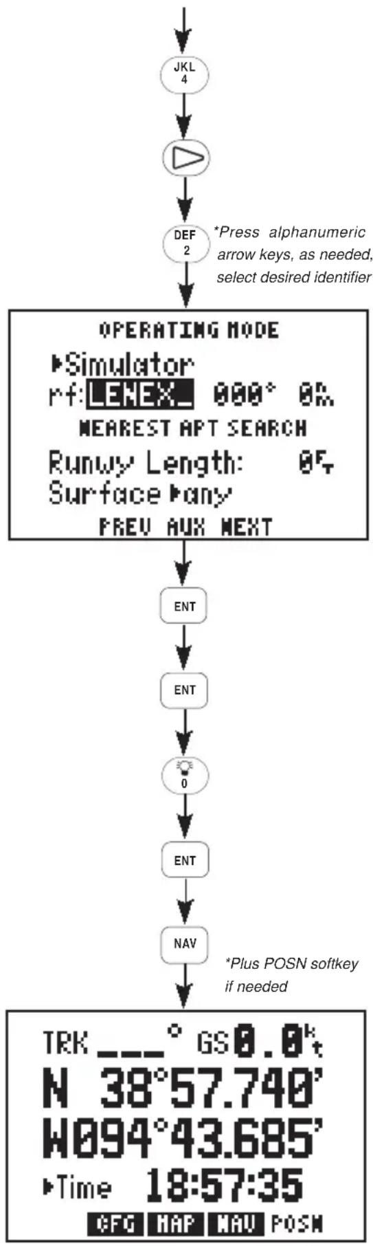
The cursor is now on the reference waypoint identifier. The intersection, LENEX, will be entered here using the alphanumeric keys.
flowchart
graph TD
    A["JKL 4"] --> B["△"]
    B --> C["DEF 2"]
    C --> D["OPERATING MODE\n▶ Simulator\nrf: LENEX 000° OK\nMEAREST APT SEARCH\nRunwy Length: OF\nSurface ▷any\nPREV AUX NEXT"]
    D --> E["ENT"]
    E --> F["ENT"]
    F --> G["0"]
    G --> H["ENT"]
    H --> I["NAV"]
    I --> J["TRK ---° GS0.0k\nN 38°57.740'\nW094°43.685'\n▶ Time 18:57:35\nCFG MAP NAV POSM"]
    D --> K["*Press alphanumeric arrow keys, as needed,\nsell desired identifier"]
    style D fill:#f9f,stroke:#333
    style I fill:#ccf,stroke:#333
Press the "4" key, followed by the right arrow key to select the letter "L".
Press the "2" key to select the letter "E".
Continue pressing the desired alphanumeric keys and, if needed, the arrow keys to enter the “LENEX” intersection. Press ENT when complete.
The cursor is over the reference bearing. Since the simulation will begin at LENEX you do not need to define a reference bearing from this point. Press ENT.
The cursor is over the reference distance. Enter a distance of zero and press ENT. The initial position is now set at the LENEX intersection.
You can view your position coordinates by pressing NAV and the POSN softkey, if needed. The Present Position Page is displayed.
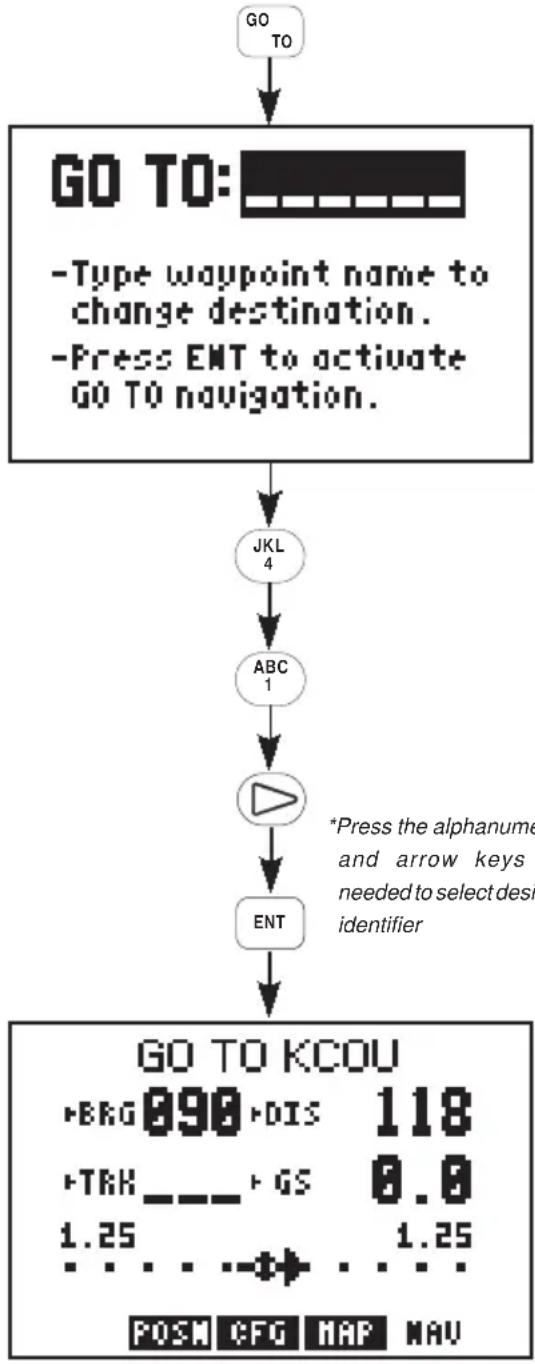
From your starting location at the “LENEX” intersection you may plot a course and navigate to a nearby airport. For this sample trip you will fly to KCOU, Columbia Regional Airport.
To select a destination waypoint...
flowchart
graph TD
    A["GO TO"] --> B["GO TO:"]
    B --> C["-Type waypoint name to change destination.<br>-Press ENT to activate GO TO navigation."]
    C --> D["JKL 4"]
    D --> E["ABC 1"]
    E --> F["▶"]
    F --> G["ENT"]
    G --> H["GO TO KCOU<br>-BRG 890-DIS 118<br>-TRK _- - GS 8.0<br>1.25 ... 1.25<br>POSM CFG MAP NAV"]
    style B fill:#f9f,stroke:#333
    note right of F
        *Press the alphanumeric and arrow keys
        needed to select design identifier
    end
Navigating to a waypoint is easy. Press GOTO and the GPS 95 will display the GOTO Page, as illustrated. Notice that the cursor is to the right of "GOTO". On this field you will enter the identifier of your destination waypoint, KCOU.
Press the "4" key to select the letter "K".
Press the "1" key followed by the right arrow key to select the letter "C".
Continue pressing the desired alphanumeric keys and, if needed, the arrow keys to enter the KCOU airport identifier. Press ENT when complete.
The Navigation Summary Page is displayed showing navigation information for your trip to KCOU.
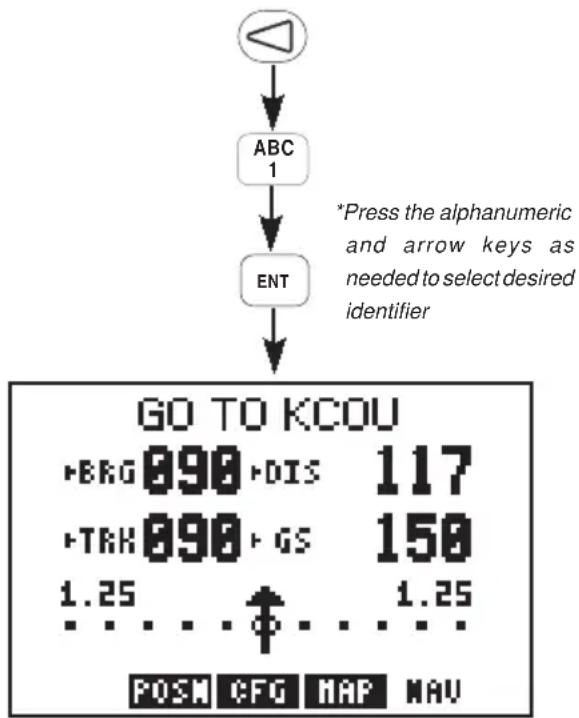
The GPS 95's simulator mode allows you to enter a ground speed which is used to animate navigation displays.
To enter a simulated speed...
flowchart
graph TD
    A["Input"] --> B["ABC 1"]
    B --> C["ENT"]
    C --> D["GO TO KCOU"]
    D --> E["+BRG 890 +DIS 117"]
    D --> F["+TRK 890 +GS 150"]
    D --> G["1.25 ... ↑ ... 1.25"]
    D --> H["POSW CFG MAP NAV"]
    style A fill:#fff,stroke:#333
    style D fill:#f9f,stroke:#333
Press the left arrow key to place the cursor on the ground speed field (bottom right).
Enter a ground speed of 150 knots. Begin by pressing the "1" key. Continue pressing the alphanumeric keys until "150" is displayed. Press ENT when finished.
The GPS 95 now displays additional navigation information as it simulates a flight to KCOU. Notice the information changing as the flight progresses.
Additional information is available from the Navigation Summary Page. You may recall from Section 5.1 that this information is viewed by highlighting one of the four cyclic fields and pressing CLR. Take a look at one of those fields now.
To view additional navigation information...
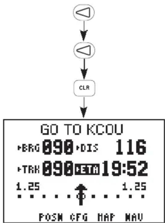
text_image
GO TO KCOU • BRG 090 •DIS 116 • TRK 090 CETA 19:52 1.25 ... ↑ ... 1.25 POSN CFG HAF NAVPress the left arrow key twice to place the cursor on the fourth cyclic field (bottom right).
Press CLR to select "ETA". This field will now show at what time (UTC) you will arrive at Columbia Regional Airport. The GPS 95's Map Display is also
useful to help “orient” yourself. The Map Display can show area airports, NAVAIDS, and intersections as points of reference.
To view the Map Display...
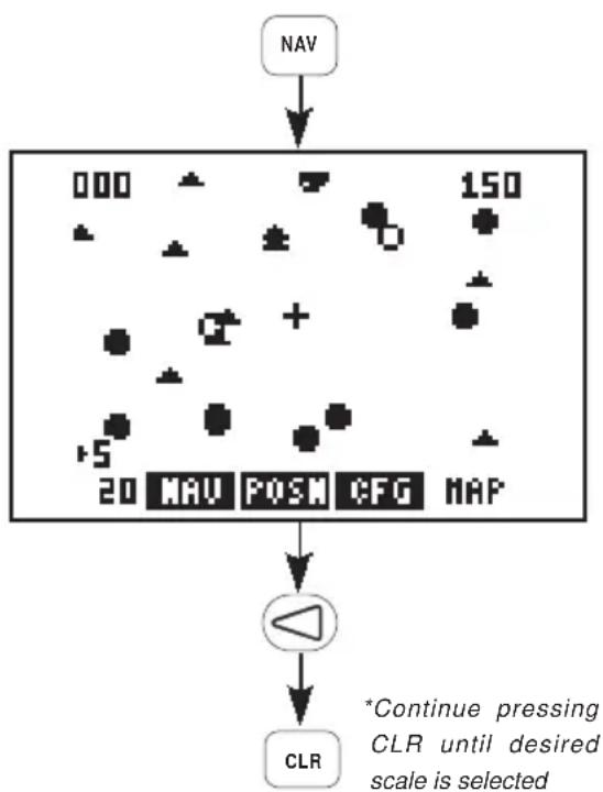
flowchart
graph TD
    A["NAV"] --> B["000 150"]
    B --> C["20 MAV POSM CFG MAP"]
    C --> D["CLR"]
    D --> E["*Continue pressing CLR until desired scale is selected"]
Press NAV.
The Map Display is shown indicating your position at the center of the screen and nearby waypoints.
Press the left arrow key to place the cursor on the scale number.
Press CLR (repeatedly) to select the desired scale.
The simulated trip has demonstrated only a small portion of the GPS 95's many features. Take a moment to experiment with your new unit. Review Chapter 5 covering types of information on the Navigation Summary Page and the Map Display. Look at waypoint information by taking another glance at Chapter 3. Read Chapter 6 to learn more about routes. Customize your unit according to your preferences as described in Chapter 8.
CHAPTER 6 ROUTES
flowchart
graph LR
    KTUL --> EOS
    EOS --> SGF
    SGF --> ActiveLeg
    ActiveLeg --> MAP
    MAP --> KSTL
    style KTUL fill:#f9f,stroke:#333
    style KSTL fill:#f9f,stroke:#333
    note1["Active from waypoint"] --> SGF
    note2["Active to waypoint"] --> MAP
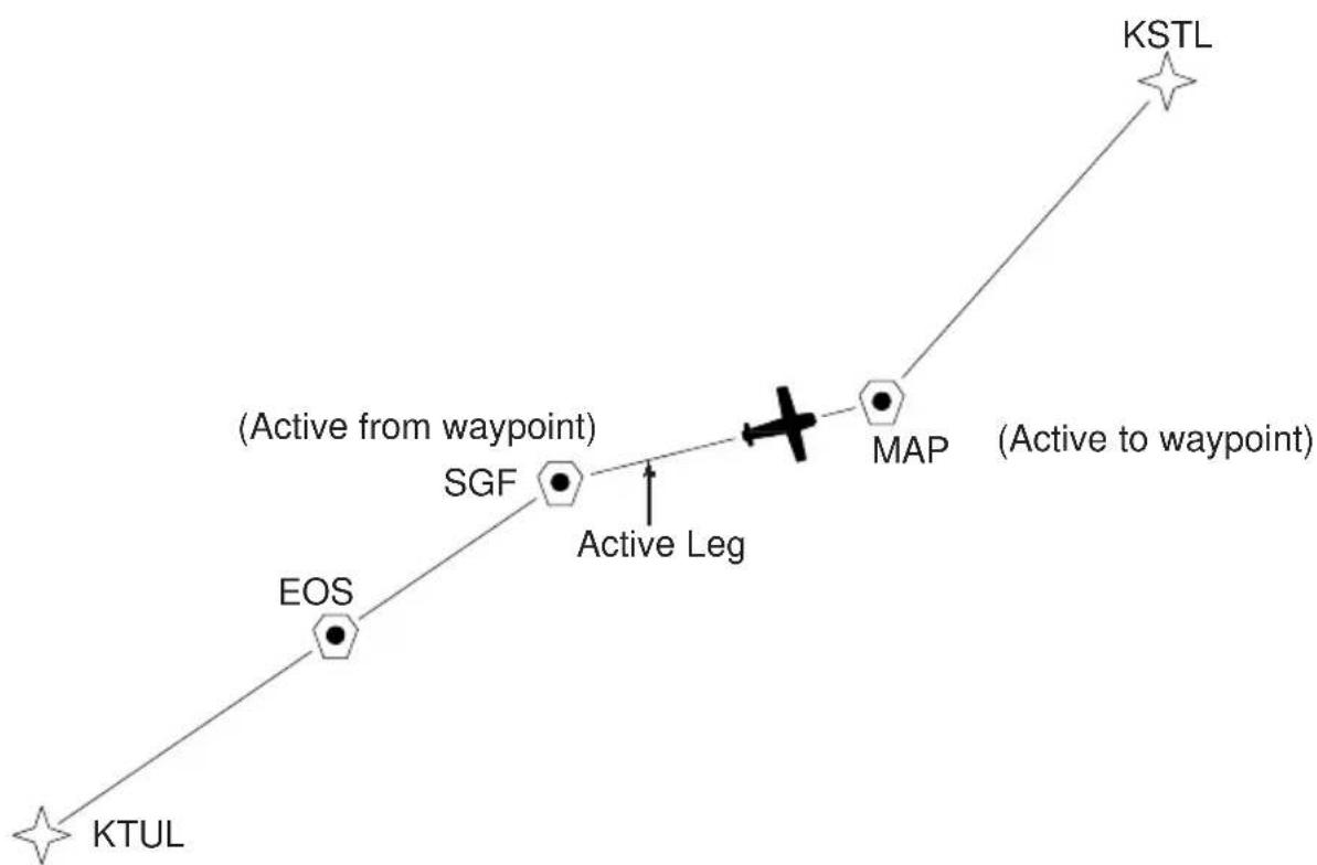
The GPS 95 offers a route navigation feature for you to navigate along a pre-defined sequence of waypoints.
The GPS 95 route capability allows you to create and store twenty routes, numbered 0 through 19, containing up to 30 waypoints each. Routes 1 to 19, the storage routes, can be activated to travel either in the order you entered the waypoints or in reverse order. Route 0, the active route, is the route you are navigating. The waypoint toward which you are navigating is called the “active to” waypoint. The waypoint immediately behind you is called the “active from” waypoint. The line that connects the “active from” and “active to” waypoints is called the “active leg.”
The GPS 95 features automatic leg selection which will select the route segment closest to your position as the active leg. The GPS 95 also features automatic leg sequencing. As you pass a waypoint in the route, the unit will automatically select the next waypoint as the “active to” waypoint.
There are 3 route pages. You may select the desired page by pressing RTE and, if needed, the appropriate softkey.
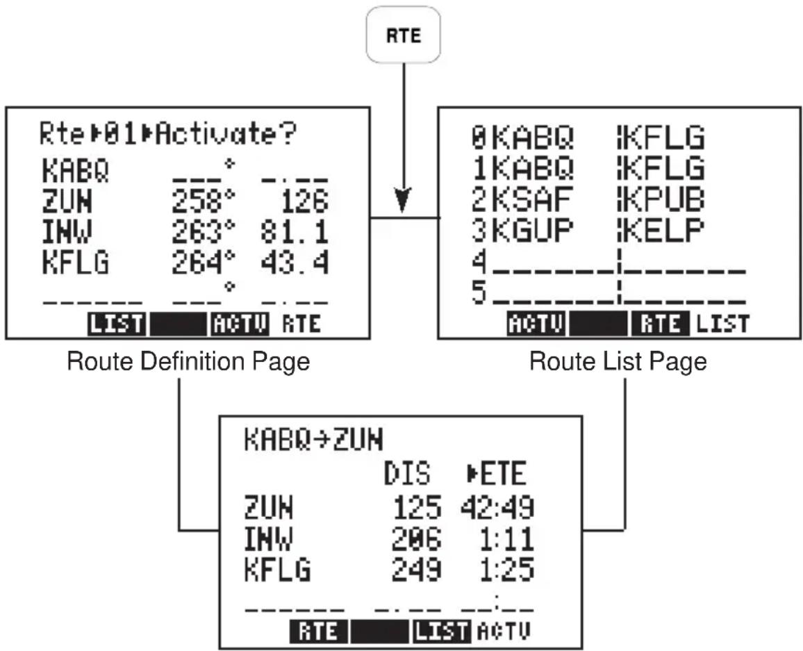
flowchart
graph TD
    A["RTE"] --> B["Route Definition Page"]
    B --> C["KABQ→ZUN"]
    C --> D["ZUN: DIS 125, ETE 42:49"]
    C --> E["INW: 206, 1:11"]
    C --> F["KFLG: 249, 1:25"]
    B --> G["LIST ACTU RTE"]
    H["0KABQ IKFLG"] --> I["Route List Page"]
    I --> J["DIS ETE"]
    I --> K["LIST ACTU"]
Active Route Page
6.1 ROUTE DEFINITION
The Route Definition page allows you to create, change, review, copy, and activate routes. Remember that route 0 is always the active route. If you create a route in route 0, you should copy it into an empty storage route (1-19). When you activate a storage route, it will be copied to route 0 for activation.
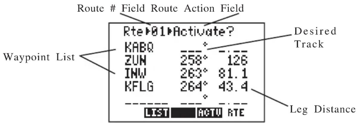
text_image
Route # Field Route Action Field Rte▶01▶Activate? Desired Track Waypoint List KABQ ZUN 258° 126 INW 263° 81.1 KFLG 264° 43.4 LIST ACTU RTE Leg DistanceOn the route number field, you may choose between routes 0 through 19 with CLR. Next to this is a route action field which allows you to activate the route, clear the route, copy the route to another location, or invert the order of the waypoints in a route and activate it. The arrow keys allow you to scroll through the list of waypoints in a route.
6.2 CREATING AND COPYING ROUTES
The Route Definition Page allows you to create new routes and to copy a route to another location for later reference.
text_image
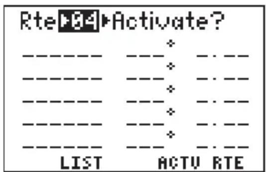
Rte▶94▶Activate? ---- ---- ---- ---- ---- ---- ---- ---- ---- ---- ---- ---- ---- ---- ---- LIST ACTU RTETo Create a Route...
- Press RTE and, if needed, the RTE softkey to display the Route Definition Page.
-
Move the cursor to the route number field and press CLR until you find an empty route. (HINT: Although the route number field is a cyclic field, to speed selection you may also enter the desired route number using the alphanumeric keys.)
-
Place the cursor on the first blank waypoint name field using the arrow keys and type in a waypoint you wish to put in the route.
- Press ENT
- Repeat this process for each waypoint you want to add, up to a total of 30.
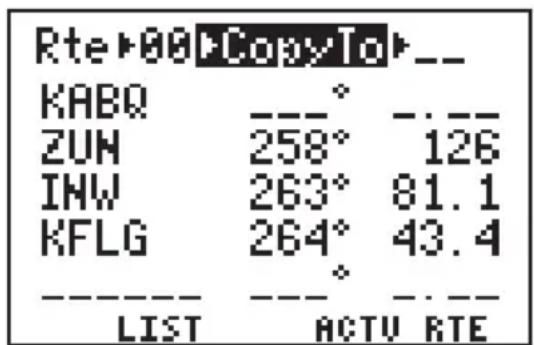
text_image
Rte▶00▶CopyTo▶-- KABQ ZUN INW KFLG LIST ACTV RTETo copy a route...
- Press RTE and, if needed, the RTE softkey to display the Route Definition Page.
-
Highlight the route number field with the cursor and select the route number to copy from with CLR.
-
Highlight the route action field with the arrow keys and press CLR until “>Copy To>” is displayed.
· A third field now appears in the top right corner. Highlight this field and select the destination route number with CLR. - Press ENT. The route is now copied.
6.3 ACTIVATING AND INVERTING ROUTES
Routes are also activated on the Route Definition Page. You may activate any route in the displayed order, or in reverse order. (NOTE: Remember, when a new route is activated, the previous contents of route 0 will be overwritten. If you wish to save route 0, be sure to copy it to an empty route first.)
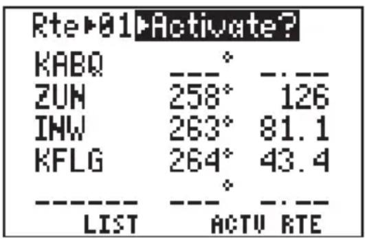
text_image
Rte▶01▶Activate? KABQ ZUN INW KFLG LIST ACTU RTETo activate a route...
- Press RTE and, if needed, the RTE softkey to display the Route Definition Page.
-
Highlight the route number field with the cursor and select the route number to activate with CLR.
-
Highlight the route action field, and with CLR select ">Activate?".
- Press ENT to activate the route.
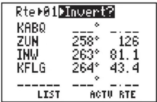
text_image
Rte▶01▶Invert? KABQ ZUN 258° 126 INW 263° 81.1 KFLG 264° 43.4 LIST ACTV RTETo invert a route...
- Follow the same steps as above for activating a route, but select ">Invert?" at the route action field.
- Press ENT to activate the route in an inverted order.
6.4 EDITING ROUTES
Existing routes may be edited from the Route Definition Page.
To Edit an Existing Route...
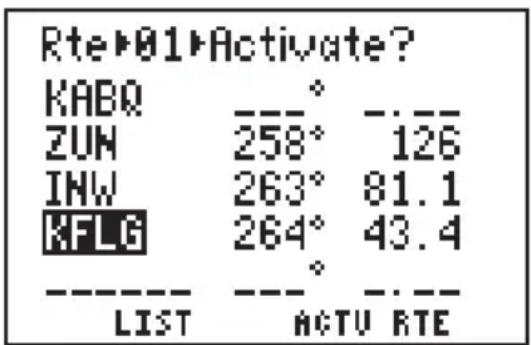
text_image
Rte▶01▶Activate? KABQ ZUN INW KFLG LIST ACTU RTE- Press RTE and, if needed, the RTE softkey to select the Route Definition Page.
- Highlight the route number field with the cursor and select the route you wish to edit.
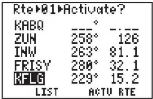
text_image
Rte▶01▶Activate? KABQ ZUN INW FRISY KFLG LIST ACTU RTE- To insert a waypoint into the route: highlight the waypoint you want to place the new waypoint in front of, type in the new waypoint name and press ENT. The new waypoint is added to the route.
- To delete a waypoint from the route: highlight the waypoint you wish to delete, press CLR and ENT.
- If you attempt to add a waypoint to a route that already contains 30 waypoints, you will be informed with the message, "Route is Full".
NOTE: You may also edit a route from the Active Route Page. (See Section 6.6.)
6.5 DELETING ROUTES
You may delete an unwanted route from the Route Definition Page.
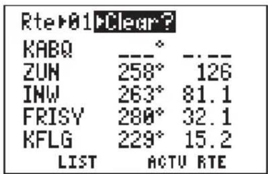
text_image
Rte▶01▶Clear? KABQ ZUN 258° 126 INW 263° 81.1 FRISY 280° 32.1 KFLG 229° 15.2 LIST ACTU RTETo delete a route...
- Highlight the route number field and select the route you wish to delete with CLR.
· Highlight the route action field and select ">Clear?" with the CLR key. - Press ENT to delete the route.
6.6 ACTIVE ROUTE
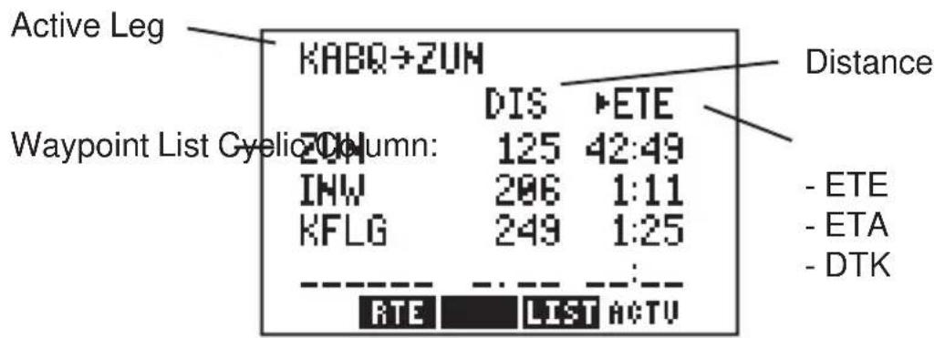
text_image
Active Leg KABQ→ZUN DIS ►ETE Waypoint List Cyelio Column: 125 42:49 INW 206 1:11 KFLG 249 1:25 ---- :- RTE LIST ACTU Distance - ETE - ETA - DTKThe Active Route Page displays the waypoints of the active route starting with the “active from” and “active to” waypoints on the top line. Press the ACTV softkey to select this page.
The waypoint list displays route waypoints starting with the “active to” waypoint. For each waypoint, additional information is available. The first column displays Distance (DIS). The second column is a cyclic field that displays Estimated Time Enroute (ETE, in hours/minutes or minutes/seconds, as appropriate), Estimated Time of Arrival (ETA), or Desired Track (DTK). You may scroll through the waypoint list with the arrow keys.
To edit the active route...
- To insert a waypoint: highlight the waypoint you want to place the new waypoint in front of, type in the new waypoint name and press ENT. The new waypoint is added to the route.
- To delete a waypoint: highlight the waypoint you wish to delete, press CLR and ENT.
6.7 ROUTE LIST
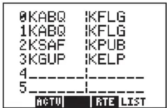
text_image
0KABQ IKFLG 1KABQ IKFLG 2KSAF IKPUB 3KGUP IKELP 4---- 5---- ACTU | RTE LISTThe Route List Page displays a list of all routes currently stored in memory. Press the LIST softkey to select this page. The Route List Page displays the route numbers (far left), beginning waypoint, and final destination waypoint. You may also activate or delete a route from the Route List Page.
To Activate a Route...
- Highlight the route you wish to activate with the arrow keys.
- Press ENT. The Route Definition Page is displayed with the “>Activate?” action highlighted.
- Press ENT to Activate the route.
To Delete a Route...
- Highlight the route you wish to delete using the arrow keys. Press CLR. The Route Definition Page is displayed with the “>Clear?” action highlighted.
- Press ENT to delete the route.
CHAPTER 7
AUTOSTORE™
The Autostore ^™ function allows you to capture your position at the touch of a button for future reference. This function saves your current position as a waypoint. Additionally, you may record your navigation path by inserting the captured waypoints directly into a route.
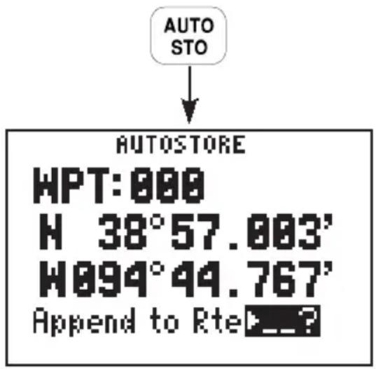
text_image
AUTO STO AUTOSTORE HPT:000 H 38°57.003' W094°44.767' Append to Rte...?The Autostore™Page displays the waypoint identifier, captured position and optional storage route. An Autostore™ waypoint name is pre-assigned as a three digit number. You may change this to any name you desire. Autostore™ waypoints may be used for any waypoint operation and will be part of the 500 available waypoints.
7.1 CREATING WAYPOINTS WITH AUTOSTORE™
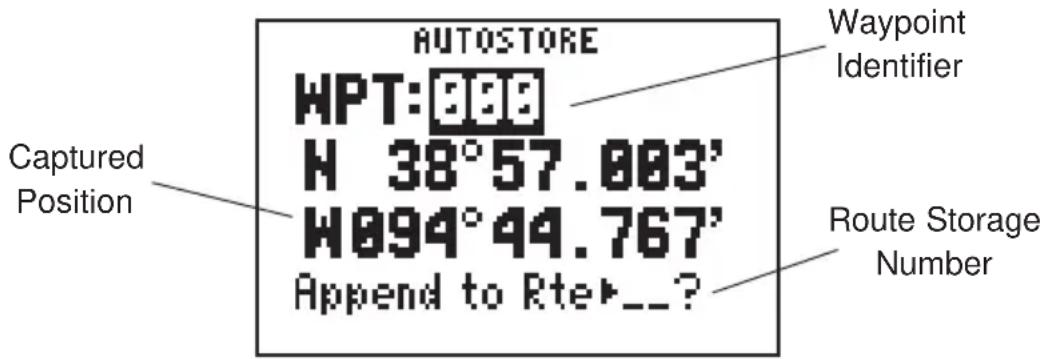
text_image
AUTOSTORE WPT:888 H 38°57.003' W094°49.767' Append to Rte▶__?You may capture and save your position as a waypoint, without adding it to a route, by leaving the route storage number field blank.
To capture present position ...
- Press AUTOSTO. The pre-assigned waypoint identifier and captured position are displayed. (NOTE: The Autostore™ location is captured as soon as you press AUTOSTO. This allows you all the time you need to change the waypoint name and/or confirm the Autostore™ operation.)
- If you wish to assign a different identifier to the waypoint: move the cursor to the waypoint name field, enter the name of your choice and press ENT. If you enter a waypoint name already used, you will be informed with the message, "WPT Exists ____" (where the blank will be filled in with the waypoint identifier). Enter a different identifier if this occurs.
- Press ENT on a blank route storage number field to save the waypoint. (If the route storage number field is not blank, the waypoint will be added to the route shown.)
7.2 BUILDING ROUTES WITH AUTOSTORE™
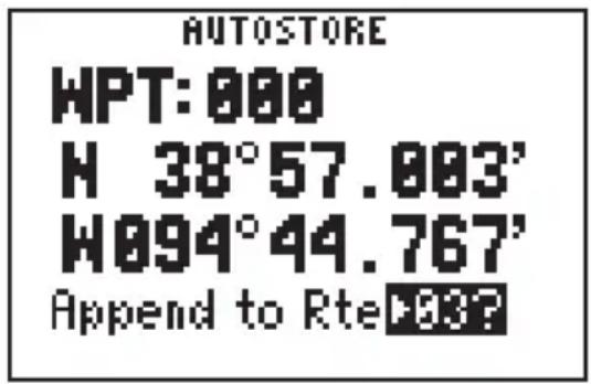
text_image
AUTOSTORE HPT: 000 H 38°57.003' W094°44.767' Append to RteThe GPS 95's Autostore™ feature may also be used to build a route as you are flying. During your flight; as you reach each airport, NAVAID, landmark, or turn to a new heading; you may capture your position and add it to a route. Once you reach your destination you can then invert the route and follow the same course back to where you started. Or, you may want the route for future reference if you wish to make the same flight again.
To build a route with Autostore™...
- From the starting location, press AUTOSTO to capture the position. (NOTE: The unit must me in 2D or 3D navigation mode when capturing your starting position. If the unit is still acquiring satellites, and you press AUTOSTO, the last known position will be captured and saved.)
- If you wish to assign a different identifier to the waypoint: move the cursor to the waypoint name field, enter the name of your choice and press ENT. If you enter a waypoint name already used, you will be informed with the message, "WPT Exists ____" (where the blank will be filled in with the waypoint identifier). Enter a different identifier if this occurs.
- Select a route to store the waypoint in by highlighting the route storage number field and pressing CLR until the desired route number is displayed. If the selected route is not empty, the Autostore™ waypoint will be added to the end of the existing route. (HINT: Although the route storage number field is a cyclic field, to speed selection you may also enter the desired route number using the alphanumeric keys.)
- Press ENT to add the waypoint to the selected route.
- Repeat these steps each time you arrive at a location you wish to add to the route, up to a total of 30 waypoints per route.
CHAPTER 8
GPS STATUS AND AUXILIARY FUNCTIONS
The GPS 95 contains a vast array of functions, many of which you may custom tailor to your preferences. Additionally, the unit can provide current status information regarding the satellites being received and display messages relevant to your current operations. You may select the desired page by pressing PWR/STAT and, if needed, the appropriate softkey.
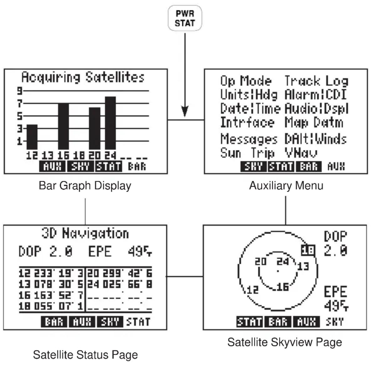
flowchart
graph TD
    A["Acquiring Satellites"] --> B["Bar Graph Display"]
    A --> C["Auxiliary Menu"]
    A --> D["3D Navigation"]
    D --> E["Satellite Status Page"]
    A --> F["Satellite Skyview Page"]
    G["PWR STAT"] --> A
8.1 BAR GRAPH DISPLAY
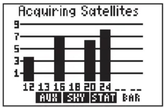
bar
Acquiring Satellites | Category | Acquiring Satellites | | :--- | :--- | | AUX | 12 | | SHY | 13 | | STAT | 16 | | BAR | 18 | | Other | 20 | | Other | 24 | The values in the table represent the count of acquiring satellites for each category. The bar labels are explicitly provided above the bars.The GPS 95 continually monitors the status of the satellites it tracks and shows that information graphically on a Bar Graph Display. Satellite numbers (1-32) are represented along the bottom of the graph; signal strength (1 to 9, weakest to strongest) is represented along the side. Once a satellite is received, a bar is displayed showing
signal strength for that satellite. If a satellite is visible, but not being received, the signal strength will be blank.
The receiver status is also shown at the top of the page. In this example, the unit is acquiring satellites. The following is a list of possible receiver status messages:
“Searching the Sky” The GPS 95 is in the process of searching the sky for visible satellites. You will also be informed of this condition with a “Searching the Sky” message.
"Acquiring Satellites" The GPS 95 is in the process of acquiring visible satellites.
"2D Navigation" The GPS 95 is in the 2D navigation mode. The unit will calculate a horizontal position, but not altitude.
"3D Navigation" The GPS 95 is in the 3D navigation mode and will calculate altitude
“Simulating Navigation” The GPS 95 is in the simulator mode. This mode should be used only for practice and trip planning. Never use this mode for actual navigation.
"Poor Coverage" The GPS 95 is unable to acquire sufficient satellites for navigation.
"Need Altitude" The GPS 95 needs altitude in order to start and/or continue 2D navigation. Go to the Present Position Page and enter the altitude. (See Section 5.4.)
"Not Usable" The GPS 95 is unusable (possibly due to incorrect initialization data or abnormal satellite conditions). Turn the unit off and back on.
When operating with an RTCM input selected, the Bar Graph Display will denote each satellite for which differential corrections are available with a “D” at the bottom of the bar. (See Section 8.11 for more information on RTCM input selections.) Furthermore, the differential navigation status will also display at the top of the page. There are two additional receiver status messages available when using
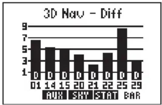
bar
3D Hau - Diff | Time | Value | |---|---| | 01 | 7 | | 14 | 5.5 | | 15 | 5 | | 20 | 4 | | 21 | 2.5 | | 22 | 4.5 | | 25 | 8.5 | | 29 | 3 |an RTCM input:
"2D Nav - Diff" The GPS 95 has calculated a differentially-corrected horizontal position. Altitude has not been corrected.
"3D Nav - Diff" The GPS 95 has calculated a differentially-corrected position, including altitude.
8.2 SATELLITE STATUS PAGE
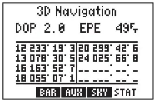
The Satellite Status Page shows the ID, azimuth, elevation, and signal quality of each visible satellite in a table format. The receiver status, again, is displayed at the top of the screen. The second line displays two system quality values - dilution of precision (DOP) and estimated position error (EPE). EPE and DOP are advisory information only and are not to be used as absolute measures of accuracy. (See Appendix B for definitions of these terms.)
8.3 SATELLITE SKYVIEW PAGE
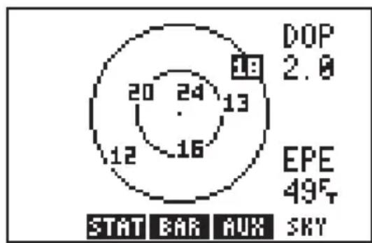
radar
| Metric | Value | |--------|-------| | DOP | 2.0 | | EPE | 49% | | STAT | 12 | | BAR | 16 | | AUX | 24 |The Satellite Skyview Page shows the azimuth and elevation of each visible satellite in a graphic sky view format. Additionally, DOP and EPE values are shown on the right hand side of the page. The display is always oriented "north up" and is useful in determining whether a satellite signal is being blocked by part of the aircraft, buildings,
mountains, or other obstructions. If a satellite is not currently being received, it will be highlighted on the display.
8.4 AUXILIARY MENU
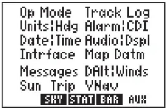
text_image
Op Mode Track Log Units!Hdg Alarm!CDI Date!Time Audio!Dspl Intrface Map Datm Messages DAlt!Winds Sun Trip VNav SKY STAT BAR AUXThe GPS 95's auxiliary pages allow you to do setup functions to customize your unit and E6-B calculations to plan your flight. The 13 auxiliary pages are accessible from the Auxiliary Menu by highlighting the page you want and pressing ENT. Once an auxiliary page is selected PREV, AUX, and NEXT page options will be displayed. The softkeys
allow changing to previous (PREV) and next (NEXT) auxiliary pages. The AUX softkey takes you back to the Auxiliary Menu. (HINT: The PREV and NEXT softkeys will only select the auxiliary pages of the same type - setups or E6-B calculations. To change between types you must return to the Auxiliary Menu first.)
The following sections describe the function of each auxiliary page.
8.5 OPERATING MODE/NEAREST AIRPORT SEARCH
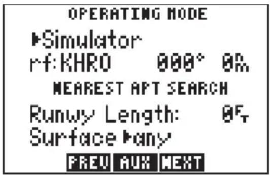
text_image
OPERATING MODE ►Simulator rf: KHRO 000° 0% MEAREST APT SEARCH Runwy Length: 0F Surface ►any FREV AUX NEXTFrom this page, you may change between various operating modes by highlighting the operating mode field and pressing CLR. You may select simulator mode, normal mode, or battery saver mode. (See Section 1.5 for a description of each mode.)
Below the operating mode field is a reference waypoint field to define an initial position. In simulator mode you may designate a starting point from which the simulation will begin. In normal and battery saver modes, the initial position may be defined to reduce satellite acquisition time.
To define an initial position...
- Select the desired operating mode by placing the cursor on the operating mode field and pressing CLR.
- Press ENT to select the desired mode.
- Enter the identifier of the desired reference waypoint (airport, VOR, NDB, intersection or user waypoint) and press ENT.
- Enter the bearing from the reference waypoint to the desired location and press ENT. The bearing will be true or magnetic depending on the unit setups. (See Section 8.7.)
- Enter the distance from the reference waypoint to the desired location and press ENT. The distance will be in nautical miles, statute miles or kilometers depending on unit setups. (See Section 8.7.) (Hint: If a distance of zero is entered, the initial position will be at the selected reference waypoint.)
The Operating Mode/Nearest Airport Search Page also allows you to select the characteristics of the GPS 95's nearest airport function. Pilots of large, high-performance aircraft may direct the nearest airport function to ignore those airports at which it would be difficult, if not impossible, to land their aircraft. You may set the minimum runway length and the surface type for airports selected by the nearest airport function.
To set the minimum runway length...
- Place the cursor on the runway length field using the arrow keys.
· Enter the minimum runway length using the alphanumeric keys. - Press ENT.
To set the desired runway surface...
- Place the cursor on the runway surface field using the arrow keys.
- Select the desired surface type by pressing CLR. You may select from any surface (any), hard surface only (hard only), soft/hard surface only (soft/hard), or water surface only (water only).
WARNING: Be extremely cautious when selecting the nearest airport search characteristics, particularly if you select a large runway length and/or water surface type. These selections are designed for specialized aircraft operations and will tend to eliminate many available airports from the nearest airport list which might otherwise be useful in the event of an emergency.
8.6 TRACK LOG SETUP

text_image
TRACK LOG Status ▶on ▶wrap Recording Criteria ▶Resolution: 0.100% Memory Used 3% Clear Track Log? FREV AUX NEXTThe Track Log Setup Page is used to configure the track log function. A track log is a record of your flight path showing where you have been up to your present position. The cyclic fields on line one allow you to turn the track storage on or off, and determine how the track log will be stored in memory.
The track storing function may be
turned on and off by highlighting the first status field and pressing CLR. From the next field, the track may be set to “wrap” around through available memory (deleting the oldest track information and using the memory to store the new track position), or to “fill” available memory and then stop. The amount of memory, used at any given moment, is also displayed. When available memory is filled or the track is no longer needed, it may be cleared by highlighting “Clear Track Log?” and pressing ENT. If the “fill” option is selected, a “memory full” message will be displayed when all available memory has been used and you must clear the track log to store additional track information.
The ground track is stored at a frequency that you can define either by: Time "Interval", "Resolution", or "Distance". Select the desired frequency unit by highlighting this field and pressing CLR.
To store the Ground Track at selected time Intervals...
- Highlight the recording criteria field (third line) and select “Interval” with CLR.
- Press ENT.
- Enter the time interval between stored positions starting with hours, then minutes, then seconds. Press ENT after entering data in each numeric field.
To store the Ground Track by Distance...
- Highlight the recording criteria field and select "Distance" with CLR.
- Press ENT.
- Enter the distance, and press ENT. When your position moves this distance in any direction, a new position is added to the stored ground track. NOTE: “Distance” storage may be preferable to “Resolution” storage if the ground track will include a large number of turns.
If the planned course will be primarily straight line travel, you should select "Resolution" storage. In this application, considerably less memory is used for the same distance traveled.
To store the Ground Track by Resolution...
- Highlight the recording criteria field and select "Resolution" with CLR.
- Press ENT.
- Enter the resolution range, and press ENT. When your position moves this defined range off a projected course line, a new position is added to the stored ground track.
8.7 UNITS/HEADING SETUP
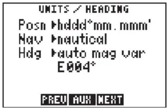
text_image
UNITS / HEADING Posn ►hddd*mm.mmm' Nav ►nautical Hdg ►auto mag var E004° FREV AUX NEXTThe Units/Heading Page is used to select the units to display for position, distance, speed and heading information. Select the desired position units by highlighting the "POSN" field and pressing CLR. You may choose between decimal degrees (hddd.ddddd°); degrees and decimal
minutes (hddd°mm.mmm'); degrees, minutes and decimal seconds (hddd°mm'ss.s"); UTM/UPS coordinates; or various other regional grids.
Select the desired distance, speed and altitude units by highlighting the "NAV" field and pressing CLR. You may choose between nautical (nautical miles/knots/feet), statute (miles/miles per hour/feet), or metric (kilometers/kilometers per hour/meters) units. (NOTE: The NAV units setting also defines the pressure, temperature and vertical speed units that will be used for E6-B calculations.)
Heading information can be displayed referencing magnetic north (automatically calculated or user-defined), referencing true north or referencing calculated grid headings. Select the desired heading reference
by highlighting the “HDG” field and pressing CLR. When the “Auto Mag Vari[ation]” option is selected, heading information will reference the automatically calculated magnetic variation shown. For most applications, the “Auto Mag” feature will provide accurate heading information. If the auto-magnetic variation is not correct, you may define the magnetic variation by selecting “User Mag Var”. If the “User Mag Var” option is selected, the magnetic variation is then entered.
To enter a user-defined magnetic variation...
- Highlight the "HDG" field and select "User Mag Var" with CLR.
- Press the right arrow key.
- The variation direction is highlighted. To change the direction, press CLR.
- Press ENT.
- Enter the variation degrees and press ENT.
8.8 ALARMS/CDI SETUP
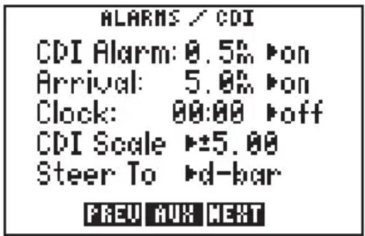
text_image
ALARMS / CDI CDI Alarm: 0.5% ▶on Arrival: 5.0% ▶on Clock: 00:00 ▶off CDI Scale ▶±5.00 Steer To ▶d-bar PREU AUX NEXTFrom the Alarms/CDI Page, you may define three alarms (and turn them on or off) and configure the graphic CDI to your preference. Alarms are available for course deviation, arrival at a destination waypoint, and an alarm clock.
The CDI alarm will notify you with an alarm tone and the message “CDI Alarm” if you have deviated off course beyond the limit that you set. (This can be useful while flying in an airway or navigating a narrow channel.)
To set the CDI alarm...
· Highlight the CDI alarm distance field.
- Enter the maximum allowable course deviation distance.
- Press ENT.
- The on/off cyclic field is highlighted. If the alarm is not turned on, press CLR.
The arrival alarm will inform you with an alarm tone and the message “Arrival at ____” (where the blank is filled in with a waypoint identifier) when you reach your destination. The alarm distance will also be used to inform you when you approach a route waypoint with the message “Approaching ____” (again, with the blank filled in by a waypoint name).
To set the arrival alarm ...
- Highlight the arrival alarm distance and enter the distance from a destination at which you want the alarm to sound.
- Press ENT.
- The on/off cyclic field is highlighted. If the alarm is not turned on, press CLR.
The GPS 95 also features an alarm clock which can provide an alarm tone and the message “Alarm Clock” at a time that you specify.
To set the alarm clock...
· Highlight the alarm clock time and enter the desired alarm time. NOTE: The alarm time may be either UTC or local time depending on the setting on the Date/Time Page. (See Section 8.9.)
- Press ENT.
- The on/off cyclic field is highlighted. If the alarm is not turned on, press CLR.
The graphic CDI may be configured to the desired scale and steering orientation. Scale settings of ±.25 , 1.25, or 5.00 units (nautical miles, statute miles, or kilometers) are available. The scale setting represents the distance from center of the CDI to either end.
To set the CDI scale...
· Highlight the CDI scale field.
- Press CLR to select the desired scale.
The CDI “Steer To” orientation determines how you interpret the “D-Bar” when it moves. You may select a “Steer to >Center” or “Steer to >D-Bar” orientation. A “Steer to Center” orientation, in effect, displays your position as the “D-Bar” and the center of CDI is the desired track. Thus, when you are off course, you would steer towards the center of the scale. A “Steer to D-Bar” orientation is just the opposite. The “D-Bar” represents the desired track and the center of the scale represents your position. When you are off
course, you then steer towards the “D-Bar”. A “Steer to D-Bar” orientation is the typical setting for aviation use and will make the GPS 95's graphic CDI respond much like the CDI on your instrument panel.
To set the CDI orientation...
- Highlight the "steer to" field.
- Press CLR to select the desired orientation.
8.9 DATE/TIME
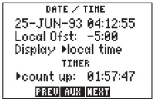
text_image
DATE / TIME 25-JUN-93 04:12:55 Local Ofst: -5:00 Display ▶local time TIMER ▶count up: 01:57:47 PREU AUX NEXTThe Date/Time Page displays the UTC (Coordinated Universal Time, Greenwich Mean Time or Zulu Time) date and time. The local offset or time difference is shown on the next line. For time zones west of the UTC zone, enter a negative offset. (HINT: The minus sign is on the "9" key.) Appendix E contains a list of time offsets.
The cyclic field for “Display” options determines which time, UTC or Local, will be displayed on all other GPS 95 pages.
To display UTC or local time...
- Highlight the time display field.
- Press CLR to select the desired time reference.
The timer field can be selected as “Count Up” or “Count Down” by highlighting and pressing CLR. This timer is useful for measuring the elapsed time since a certain event, or it can tell you when a specified amount of time has expired.
To set the count up timer...
- Place the cursor on the timer option field.
- Press CLR to select "count up".
- Press the right arrow key.
- Press CLR and ENT to clear the hours field.
- Press CLR and ENT to clear the minutes field.
- Press CLR and ENT to clear the seconds field. The count up timer will begin counting the elapsed time.
To set the count down timer...
- Place the cursor on the timer option field.
- Press CLR to select "count down".
- Press the right arrow key.
- Enter the number of hours to count down from and press ENT.
- Enter the number of minutes to count down from and press ENT.
- Enter the number of seconds to count down from and press ENT. The count down timer will begin counting down from the selected time.
8.10 AUDIO AND DISPLAY SETUP
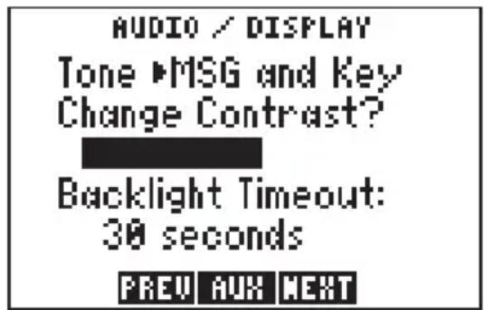
text_image
AUDIO / DISPLAY Tone ▶MSG and Key Change Contrast? Backlight Timeout: 30 seconds PREV AUX NEXTFrom the Audio/Display Page you can turn the message and/or keypad tones on and off, change the display contrast and change the time-out for the display backlighting.
The tone option allows you to turn the GPS 95's audio tone on or off as desired. You may turn the keypad
feedback tone off, but leave the message tone on; have both tones on; or have both tones off.
To turn audio tones on/off...
- Highlight the tone option field.
- Press CLR to select the desired option.
You may also adjust the contrast of the GPS 95 display to your preferences.
To change the display contrast...
· Highlight "Change Contrast?" and press ENT.
- The contrast bar is highlighted. Press the left or right arrow key to change the contrast level.
- When the desired contrast level is reached, press ENT.
The backlighting time-out determines the length of time the display and keypad backlighting will remain on. If no keys are pressed for the specified time, the backlighting will automatically shut off to conserve battery power.
To set the backlighting time-out...
- Highlight the backlighting time-out field.
- Enter the desired time for backlighting to remain on. If you wish to have the backlighting on at all times, enter zero.
- Press ENT.
8.11 INTERFACE SETUP
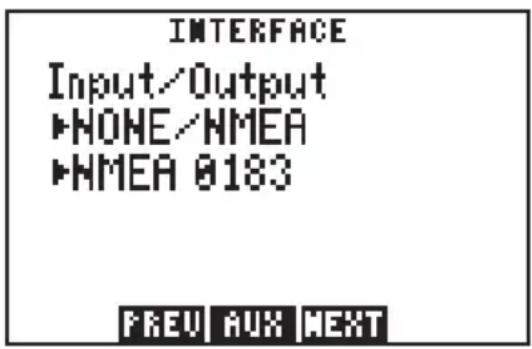
text_image
INTERFACE Input/Output ▶NONE/NMEA ▶NMEA 0183 PREV AUX NEXTFrom the Interface Page, you may select the input and/or output format needed to connect your GPS 95 to other equipment: PC, NMEA device, etc. You may select no input/output (NONE/NONE), GARMIN input/output (GARMIN/GARMIN), NMEA output (NONE/NMEA), RTCM input/NMEA output (RTCM/NMEA) or RTCM input (RTCM/NONE).
When the NMEA output is selected a second cyclic field appears. From this second field you may select the desired NMEA format: NMEA 0180, NMEA 0182, or NMEA 0183.
To select a NMEA output...
- Place the cursor on the input/output format field.
- Press CLR until the desired NMEA output option (NONE/NMEA or RTCM/NMEA) is displayed.
- Press the right arrow key.
- Select the desired NMEA format by pressing CLR.
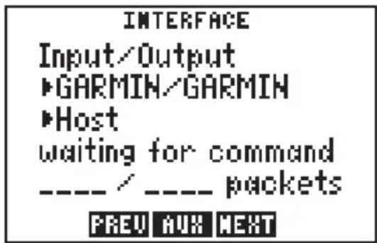
text_image
INTERFACE Input/Output ►GARMIN/GARMIN ►Host waiting for command ---- / ---- packets PREU AUX NEXTA second cyclic field also appears when the GARMIN input/output is selected. The GARMIN option allows you to exchange data such as waypoints, routes, track logs and satellite almanac data with another GPS 95 or with a PC-compatible computer. You may select between acting as a HOST to data exchanges (HOST), requesting data (REQUEST) or sending data (SEND). During the data transfer process the number of data packets being exchanged will be displayed.
To select GARMIN input/output...
- Place the cursor on the input/output format field.
- Press CLR until the GARMIN input/output option is selected.
- Press the right arrow key.
- Select "HOST", "REQUEST", or "SEND" by pressing CLR. (NOTE: You should select the "HOST" option when using the GPS 95 with a PC. When exchanging data between two GPS 95s, one should be set to "HOST" and the second should be set to the desired data transfer option - "REQUEST" or "SEND".)
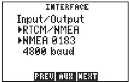
text_image
INTERFACE Input/Output ▶RTCM/NMEA ▶NMEA 0183 4800 baud PREV AUX NEXTThe GPS 95 can use Differential GPS (DGPS) corrections in RTCM SC-104 version 2.0 format. DGPS corrections in this format can be received from an external device (capable of output in 6 to 8 byte format as specified by RTCM SC-104 version 2.0) by connecting the device to the input port on the back of
the GPS 95 and selecting an RTCM input interface mode. Two RTCM input modes are available; one which allows no output and another which allows NMEA output in 0180, 0182, or 0183 format.
To select an RTCM input...
- Place the cursor on the input format field.
- Press CLR until the desired RTCM input option (RTCM/NONE or RTCM/NMEA) is displayed.
- Press the right arrow key.
- If RTCM/NONE is selected: Press CLR to select the appropriate baud rate.
- If RTCM/NMEA is selected: Press CLR to select the desired NMEA output format. (NOTE: With RTCM/NMEA selected the RTCM baud rate is automatically set to 1200 or 4800.)
If the RTCM input is selected, but the GPS 95 is not connected to an RTCM device, the unit will alert you with the message “No RTCM Input”. If the GPS 95 does not receive sufficient data to compute a DGPS-corrected position, the message “No DGPS Position” will appear.
8.12 MAP DATUM SELECTION

text_image
MAP DATUM ►Pre-defined WGS 84 Change? PREV AUX NEXTSelect the desired map datum reference from the Map Datum Page. You may choose from 102 pre-defined map datums, or you may define your own. If the sectional/chart you are using specifies a reference datum, select that datum on your GPS 95. If the sectional/chart does not specify a reference datum, you may select each datum applicable to your region until you find the datum that provides the best positioning at a known point. NOTE: The GPS 95 is shipped from the factory with the WGS 84 datum selected.
To change the pre-defined datum...
· Highlight the "Change?" field and press ENT.
· With the arrow keys, find the desired datum and highlight it.
- Press ENT. The new datum is selected.
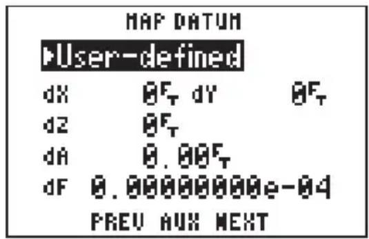
text_image
MAP DATUM User-defined dX θF, dY θF, dZ θF, dA θ.θθF, dF 0.00000000e-04 PREV AUX NEXTThe user-defined datum option allows you to custom-tailor a datum reference from which all position coordinates are calculated. All entries are defined as differences from the WGS 84 standard datum. (CAUTION: Selection and use of the user datum function is for individuals experienced in the use of map datums. If the pre-defined map datums do not correspond to the chart you are using and you are unsure of the correct entries required to correspond to that chart, contact the chart manufacturer. Incorrect entries for a user-defined datum may result in substantial position errors.)
To define a user datum...
- Place the cursor over the cyclic field on line one.
- Press CLR to select "User-defined".
- Enter the 5 parameters of the user map datum. The sign of the parameters should follow the convention: WGS 84 - local geodetic system.
8.13 MESSAGES

text_image
MESSAGES Prox Alarm GARMIN HSGYou may recall from Section 2.6 that some messages will remain on the Message Page after being viewed. When this occurs, the "MSG" annunciator remains on (but does not flash) in the lower left corner. To view these messages, select "Messages" from the Auxiliary Page. (See Appendix A for a description of available messages.)
8.14 DENSITY ALTITUDE/TRUE AIRSPEED/WINDS ALOFT
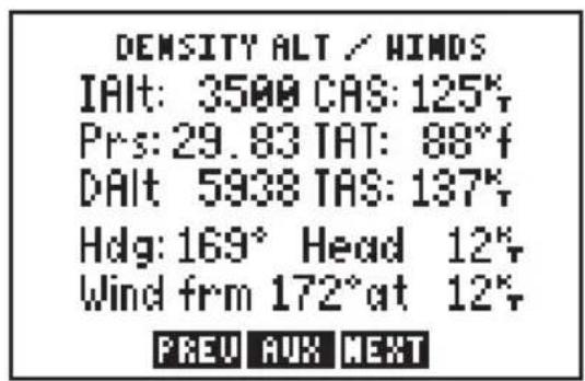
text_image
DENSITY ALT / HINDS IAlt: 3500 CAS: 125% Prs: 29.83 IAT: 88°f DAlt 5938 TAS: 137% Hdg: 169° Head 12% Wind frm 172°at 12% PREU AUX NEXTThe GPS 95 provides density altitude, true airspeed (TAS) and winds aloft calculators for your convenience. The density altitude and TAS calculations will help you determine critical aircraft performance data.
To calculate density altitude and true airspeed...
- Place the cursor on the indicated altitude (IAlt) field.
- Enter the indicated altitude from your altimeter and press ENT.
- Enter your calibrated airspeed (CAS) and press ENT. If you do not know your calibrated airspeed, use indicated airspeed instead.
- Enter your current altimeter setting and press ENT.
- Enter the total air temperature (TAT). The GPS 95 will display the resulting density altitude and true airspeed. (NOTE: TAT is the temperature of the air including the heating effect caused by speed. The temperature read on a standard outside air temperature gauge found in most piston aircraft is TAT.)
The winds aloft calculation determines the direction (true) and speed of the wind. This calculation requires TAS and heading information. If you have already calculated density altitude and TAS, the TAS value will be used for the winds aloft calculation; otherwise you may enter the correct TAS value.
To calculate winds aloft...
- If you have not already calculated TAS: place the cursor over the TAS field, enter the correct true airspeed and press ENT.
- Place the cursor over the heading (Hdg) field.
- Enter the current heading (magnetic) from your heading indicator and press ENT. The GPS 95 will display the wind direction, speed, and the head/tail wind you are encountering.
8.15 SUNRISE/SUNSET PLANNING
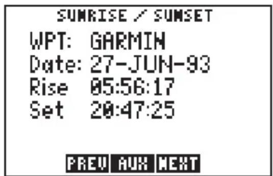
text_image
SUMRISE / SUNSET WPT: GARMIN Date: 27-JUN-93 Rise 05:56:17 Set 20:47:25 PREV AUX NEXTThe Sunrise/Sunset Page allows you to calculate the sunrise and sunset times for a given waypoint location on a selected date (from the year 1990 through 2089).
To calculate the sunrise/sunset times for a waypoint...
- Highlight the waypoint name field and enter the desired waypoint name.
- Press ENT.
- The date field is highlighted. Enter the day, then month, then year to calculate the sunrise/sunset times for. Press ENT on each alphanumeric field.
- Once the year is selected and ENT is pressed, the calculated sunrise and sunset times will be shown. Please note that the times shown will be either UTC or local depending on the selection made on the Date/Time Page. (See Section 8.9.)
8.16 TRIP AND FUEL PLANNING
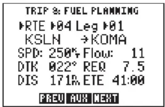
text_image
TRIP & FUEL PLANNING ►RTE ►04 Leg ►01 KSLN →KOMA SPD: 250% Flow: 11 DTK 022° REQ 7.5 DIS 171R ETE 41:00 PREU AUX NEXTThe Trip and Fuel Planning Page allows you to calculate time and fuel requirements between any two waypoints or for any programmed route. On the first cyclic field, you will choose between waypoint (WPT) or route (RTE) planning by highlighting and pressing CLR. If route planning is
selected, you would then select the desired route number and the portion of the route (a given leg or all of the route) to calculate for.
The final step is to enter speed and fuel flow rates. The GPS 95 will then calculate the desired track (DTK), fuel requirements (REQ), distance (DIS), and estimated time enroute (ETE).
To perform a trip and fuel plan, waypoint to waypoint...
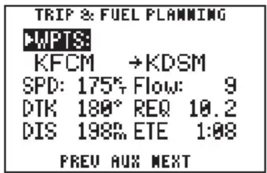
text_image
TRIP & FUEL PLANNING WPTS: KFCM →KDSM SPD: 175% Flow: 9 DTK 180° REQ 10.2 DIS 198% ETE 1:08 PREV AUX NEXT- Highlight the first cyclic field (top left), and press CLR to select "WPTS:".
- Highlight the waypoint name field (second line), and enter the first waypoint name followed by ENT.
- The second waypoint name field is now highlighted. Enter the second waypoint name followed by ENT.
- The speed (SPD) field is highlighted. Enter the planned speed, and press ENT.
- The fuel flow (Flow) field is highlighted. Enter the estimated fuel flow followed by ENT.
- The GPS 95 will now display the calculated figures.
To perform a trip and fuel plan for a route...
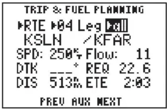
text_image
TRIP & FUEL FLANNING ▶RTE ▶04 Leg ▶all KSLN /KFAR SPD: 250% Flow: 11 DTK __-* REQ 22.6 DIS 513% ETE 2:03 PREV AUX NEXT- Highlight the first cyclic field (top left) and select "RTE" with CLR.
- Highlight the next cyclic field and select the desired route number by pressing CLR.
-
Highlight the “Leg>” field and select the desired leg, or select “All” for the entire route, using CLR.
-
Highlight the “SPD:” field and enter the planned speed, followed by ENT.
- Highlight the “Flow:” field and enter the estimated fuel flow followed by ENT.
· The GPS 95 will now display the calculated figures.
NOTE: When “all” is selected, no desired track (DTK) will be shown since this value only applies to an individual leg.
8.17 VERTICAL NAVIGATION PLANNING
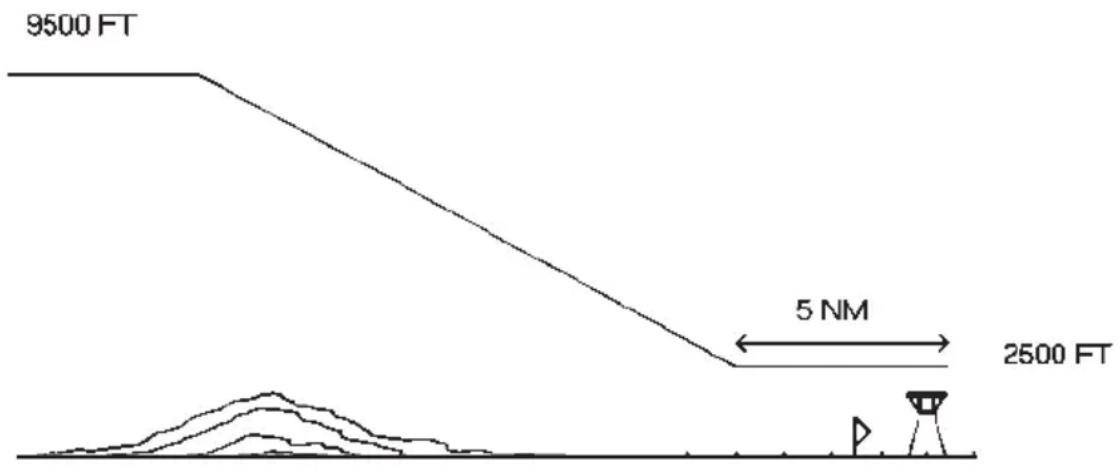
text_image
9500 FT 5 NM 2500 FTVERTICAL NAVIGATION
Frm: 9500 To: 2500
By: 5.0% Before
Waypoint ▶KFSD
At: 250fpm VH▶On
Begin In 43:17
PREV AUX NEXT
Pilots will find the GPS 95's vertical navigation (VNAV) function useful for calculating vertical speed requirements. In order to use the VNAV feature, aircraft ground speed must be greater than 35 knots.
To calculate vertical speed requirements...
- Place the cursor on the initial (Frm) altitude field.
- Enter the initial altitude and press ENT.
- Enter the final (To) altitude and press ENT.
- Enter the offset distance, from the desired waypoint, at which you will reach your final altitude. Press ENT.
- Select "Before" if the offset is before the waypoint, or "After" if the offset is beyond the waypoint, by pressing CLR.
- If an active route is being used: press CLR to select the route waypoint to which the offset applies.
- You now have defined how far before, or after, the indicated waypoint you wish to be at the final altitude. The GPS 95 will display the required vertical speed.
To activate the VNAV function...
- Review the calculated vertical speed. If you wish to change the vertical speed: place the cursor on the vertical speed (At) field, enter the desired vertical speed and press ENT.
- Place the cursor over the "VN" field.
- Press CLR to turn the VNAV function on. The VNAV status on the bottom line will change from “Enter VNAV Profile” to “Begin at ____” (with the blank indicating how long before the maneuver should begin), or “Navigating” if the VNAV maneuver is already in progress. You will be informed with the message “Start Altitude Change” when you are less than 15 seconds from the point at which the VNAV maneuver is to begin.
When VNAV is active, this page will recommend the altitude and vertical speed required to complete the maneuver. Remember that these are only recommendations. You will be informed with the message “Final Altitude Alert” when the recommended altitude is within 1000 feet of the final altitude. The VNAV function will be cancelled automatically if the active route (or GOTO) is changed in any way (e.g., setting a new GOTO destination or adding a waypoint to a route). You will be informed with the message “VNAV Cancelled” if this occurs. If the aircraft ground speed does not exceed 35 knots, or a route waypoint that has already been passed is selected, the GPS 95 will display an “Invalid profile” status on the bottom line. The GPS 95 will display “No Active Waypoint” on the bottom line if no route, or GOTO destination, has been activated.
WARNING: Altitude and climb rate should be controlled only by the pilot in command with due regard for airspeed and other aircraft performance limitations.
CHAPTER 9
SAMPLE TRIP USING ROUTES
Now that you have gained a basic understanding for your GPS 95, you are ready to explore the route capabilities of this unit. The sample illustrations in this chapter assume that the factory default settings have not been changed. If you have changed these parameters the unit may display slightly different data than presented here.
You are planning a trip from St. Petersburg, Florida (St. Petersburg - Clearwater International) to the Dry Tortugas (a user waypoint) and then on to Key West, Florida (Key West International). Turn on the GPS 95 to begin this sample trip.
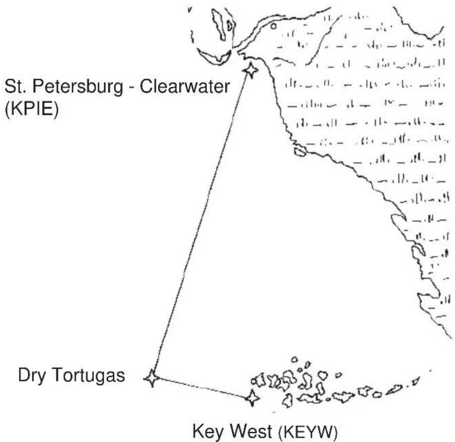
text_image
St. Petersburg - Clearwater (KPIE) Dry Tortugas Key West (KEYW)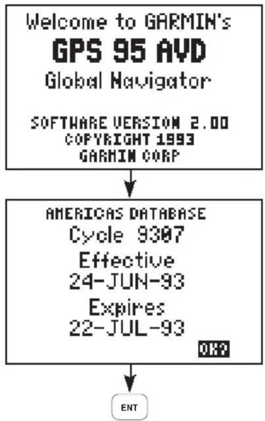
flowchart
graph TD
    A["Welcome to GARMIN's GPS 95 AVD\nGlobal Navigator"] --> B["SOFTWARE VERSION 2.00\nCOPYRIGHT 1993\nGARMIN CORP"]
    B --> C["AMERICAS DATABASE\nCycle 9307\nEffective\n24-JUN-93\nExpires\n22-JUL-93"]
    C --> D["ENT"]
The welcome screen is displayed and the GPS 95 performs several self tests.
After about five seconds the Database Page is displayed. Review the page to see if the database is current and press ENT to confirm the page.
Setting the simulator mode and initial position...
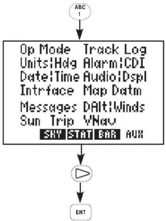
flowchart
graph TD
    A["ABC 1"] --> B["Op Mode Track Log Units!Hdg Alarm!CDI Date!Time Audio!Dspl Infrface Map Datm Messages DAlt!Winds Sun Trip VNav SKY STAT BAR AUX"]
    B --> C["Play button"]
    C --> D["ENT"]
Select the Auxiliary Menu by pressing the AUX softkey (the "1" key in this case).
Press the right arrow key to place the cursor over "op mode" and press ENT.
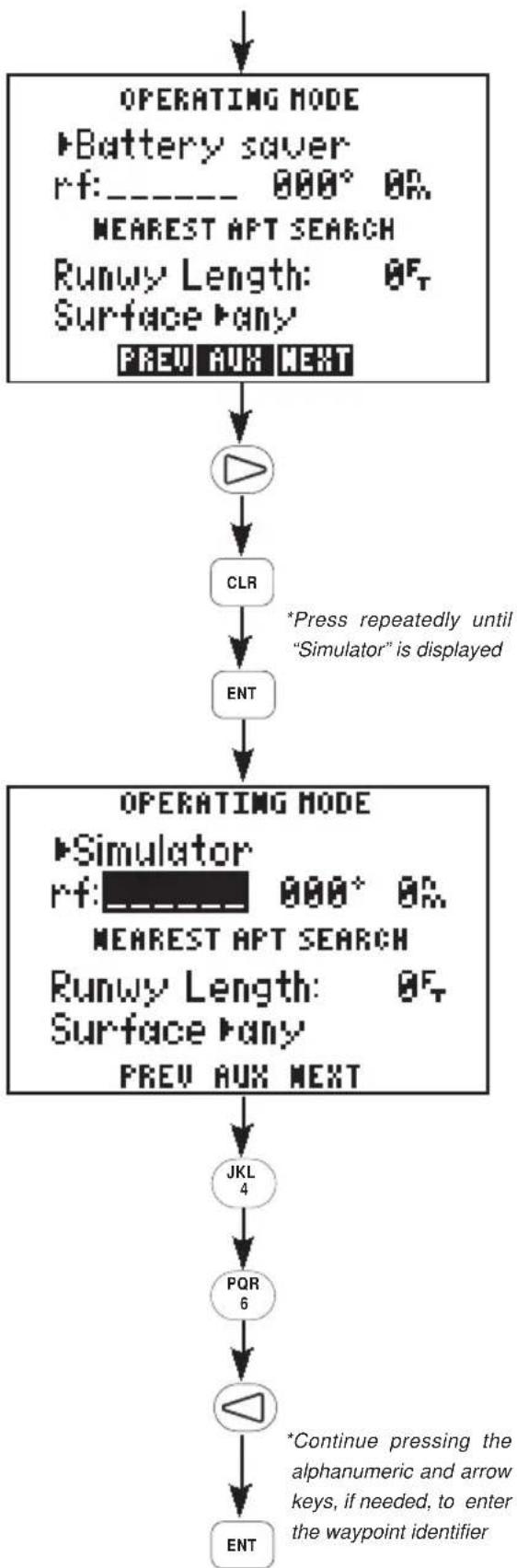
flowchart
graph TD
    A["OPERATING MODE\n▶Battery saver\nrf:______ 000° 0%"]
    A --> B["NEAREST APT SEARCH\nRunwy Length: 0%"]
    A --> C["Surface ▶any\nPREV AUX NEXT"]
    C --> D["▶"]
    D --> E["CLR"]
    E --> F["ENT"]
    F --> G["OPERATING MODE\n▶Simulator\nrf:______ 000° 0%"]
    G --> H["NEAREST APT SEARCH\nRunwy Length: 0%"]
    H --> I["Surface ▶any\nPREV AUX NEXT"]
    I --> J["JKL 4"]
    J --> K["PQR 6"]
    K --> L["◀"]
    L --> M["*Continue pressing the alphanumeric and arrow keys, if needed, to enter the waypoint identifier"]
    M --> N["ENT"]
The Operating Mode Page is displayed showing the current operational mode.
Press the right arrow to place the cursor on the operational mode field.
Press CLR (repeatedly) until "Simulator?" is displayed.
Press ENT to select simulator mode.
The cursor is on the reference identifier field. Set the initial position by entering the identifier for St. Petersburg - Clearwater International Airport (KPIE). (NOTE: This sample trip assumes that the Americas database is used. If you are using the International database you may create user waypoints using the coordinates given below, or you may follow these general steps, but substitute waypoints from your area of interest.)
Press the "4" key to select the letter "K".
Press the "6" key followed by the left arrow key to select the letter "P".
Continue pressing the alphanumeric and, if needed, arrow keys until the waypoint identifier has been entered. Press ENT when complete.
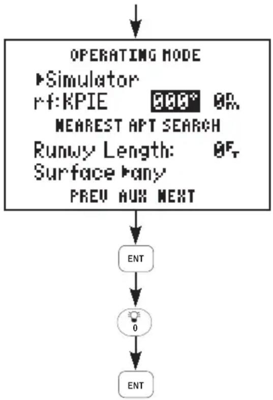
flowchart
graph TD
    A["OPERATING MODE"] --> B["Simulator"]
    B --> C["RF:KPIE 900° OR NEAREST APT SEARCH"]
    C --> D["Runway Length: 95° Surface ▷any PREV AUX NEXT"]
    D --> E["ENT"]
    E --> F["0"]
    F --> G["ENT"]
Since the trip will begin at the airport there is no need to define a reference bearing from this waypoint. Press ENT.
Enter a distance of zero and press ENT.
Before you begin the trip, all waypoints used along the route must be in memory. If you are using the Americas Database, only the location for the Dry Tortugas area needs to be entered into memory. If you are using the International Database, all waypoints for this trip must be entered as user waypoints. (Alternatively, if you are using the International Database, you may follow the general steps outlined in this sample trip, but substitute waypoints for your area of interest.) Below are the identifiers and locations for waypoints used in this sample trip:
| Indent Latitude Longitude | |
| KPIE N27°54.646' W082°41.244'DRYTG N24°38.430' W083°08.301'KEYW N24°33.370' W081°45.574' |
Creating the "DRYTG" user waypoint...
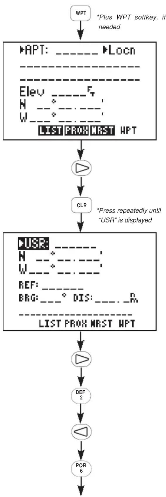
flowchart
graph TD
    A["WPT"] --> B["*Plus WPT softkey, if needed"]
    B --> C["HPAT: ---- ▶Locn\n----\nElev ---- F\nH ----\nW ----\nLIST PROX MRST HPT"]
    C --> D["CLR"]
    D --> E["*Press repeatedly until "USR" is displayed"]
    E --> F["HPUR: ----\nH ----\nW ----\nREF: ----\nBEG: ----° DIS: ---- R\n----\nLIST PROX MRST HPT"]
    F --> G["DEL 2"]
    G --> H["△"]
    H --> I["PQR 6"]
Press WPT and the WPT softkey, if needed, to select the Waypoint Definition Page.
Press the right arrow key to place the cursor on the waypoint category field.
Press CLR (repeatedly) until "USR" is displayed. The Dry Tortugas area will be added to memory as a user waypoint.
Press the right arrow key to place the cursor on the waypoint identifier field.
Enter the waypoint identifier, DRYTG, using the alphanumeric and arrow keys. Begin by pressing the "2" key, followed by the left arrow, to select the letter "D".
Press the "6" key, followed by the right arrow, to select the letter "R".
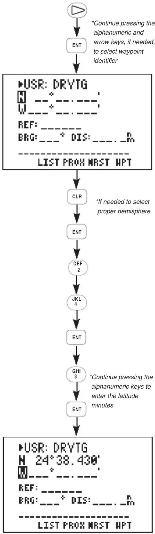
flowchart
graph TD
    A["Start"] --> B["ENT"]
    B --> C["USR: DRYTG\nN ---\nW ---\nREF: ---\nBEG: __° DIS: ___. _R\nLIST PROX MRST HPT"]
    C --> D["CLR"]
    D --> E["ENT"]
    E --> F["DEF 2"]
    F --> G["JKL 4"]
    G --> H["ENT"]
    H --> I["GHI 3"]
    I --> J["ENT"]
    J --> K["USR: DRYTG\nM 24°38.430\n\n---\nREF: ---\nBEG: __° DIS: ___. _R\nLIST PROX MRST HPT"]
    style A fill:#fff,stroke:#000
    style K fill:#fff,stroke:#000
Continue pressing the alphanumeric and, if needed, arrow keys until the waypoint identifier has been entered. Press ENT when complete.
Enter the latitude of the Dry Tortugas (N 24°38.430'). Begin by selecting the proper hemisphere, If "N" for north is not displayed, press CLR.
Press ENT when the proper hemisphere is selected.
Enter the latitude degrees. Press the "2" key and the "4" key. Press ENT when complete.
Enter the latitude minutes. Begin by pressing the "3" key.
Continue pressing the alphanumeric keys until the latitude minutes have been entered. Press ENT when complete.
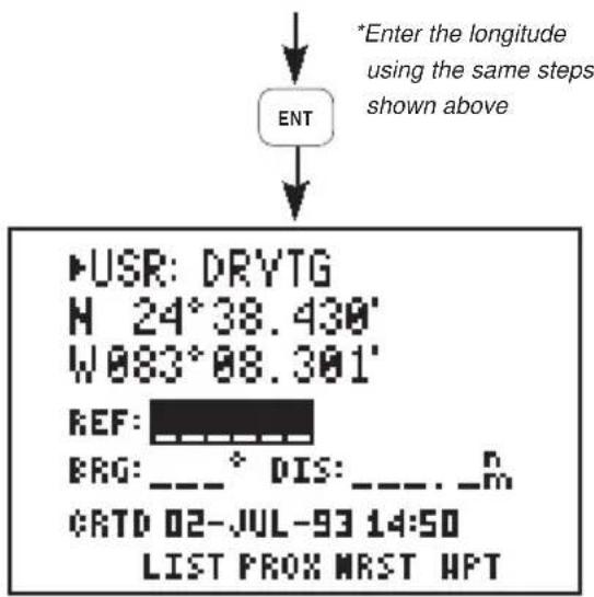
text_image
*Enter the longitude using the same steps shown above ENT •USR: DRYTG M 24°38.430' W083°08.301' REF: ERG: _ _ ^ DIS: _ _ . _ m CRTD 02-JUL-93 14:50 LIST PROX MRST HPTEnter the longitude of the Dry Tortugas (W 083°08.301') in the same manner as was used for the latitude.
Press ENT when you are finished. (NOTE: You do not need to enter the leading zero for degrees or minutes. In both cases you may begin by pressing the "8" key.)
This trip will take you to an intermediate destination (Dry Tortugas) and then a final destination (Key West). You could go to each destination using the GOTO function as described in Chapter 4. (Select GOTO DRYTG, then, upon reaching DRYTG, select GOTO KEYW.) However, for this sample trip, the route capabilities of the GPS 95 will be utilized.
To create the sample route...
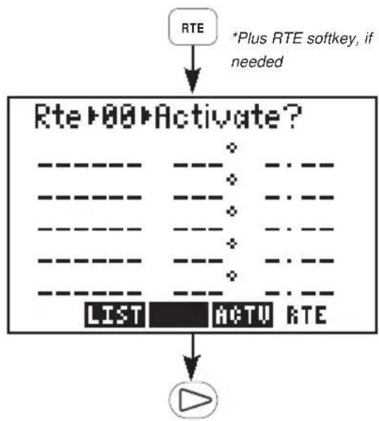
flowchart
graph TD
    A["RTE"] --> B["+Plus RTE softkey, if needed"]
    B --> C["Rte▶00▶Activate?"]
    C --> D["LIST"]
    C --> E["ACTV"]
    C --> F["RTE"]
    D --> G["Play Button"]
    E --> G
    F --> G
Press RTE and the RTE softkey, if needed, to select the Route Definition Page.
Press the right arrow to place the cursor on the route number field.
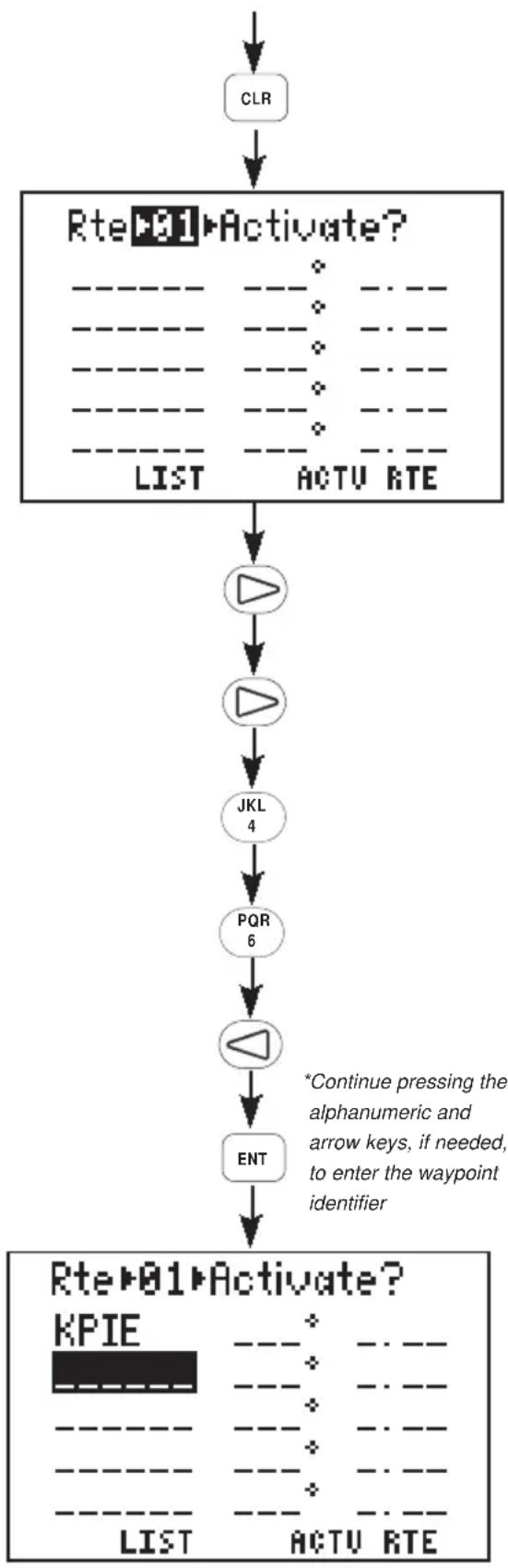
flowchart
graph TD
    A["CLR"] --> B["Rte▶01▶Activate?"]
    B --> C["LIST"]
    B --> D["ACTU RTE"]
    C --> E["▶"]
    D --> F["▶"]
    F --> G["JKL 4"]
    G --> H["PQR 6"]
    H --> I["◀"]
    I --> J["ENT"]
    J --> K["Rte▶01▶Activate?"]
    K --> L["KPIE"]
    L --> M["LIST"]
    L --> N["ACTU RTE"]
    style K fill:#f9f,stroke:#333
    note right of K
        *Continue pressing the alphanumeric and arrow keys, if needed, to enter the waypoint identifier
    end
Press CLR to select route 1. Notice that the route is empty; it does not contain any waypoints. (If route 1 is not empty, select a different route.)
Press the right arrow key twice to place the cursor on the first waypoint identifier field.
Enter the identifier for St. Petersburg - Clearwater International Airport (KPIE). Begin by pressing the "4" key to select the letter "K".
Press the "6" key, followed by the left arrow key, to select the letter "P".
Continue pressing the alphanumeric and, if needed, arrow keys until the waypoint identifier is added to the route. Press ENT when complete. The cursor is on the second waypoint identifier field.
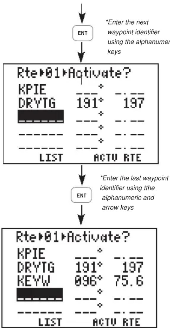
flowchart
graph TD
    A["ENT"] --> B["Rte-01 Activate?"]
    B --> C["LIST ACTU RTE"]
    C --> D["ENT"]
    D --> E["Rte-01 Activate?"]
    E --> F["LIST ACTU RTE"]
    style A fill:#f9f,stroke:#333
    style B fill:#ccf,stroke:#333
    style C fill:#cfc,stroke:#333
    style D fill:#fcc,stroke:#333
    style E fill:#cff,stroke:#333
Enter the identifier for the Dry Tortugas user waypoint (DRYTG) using the alphanumeric and arrow keys. Press ENT when complete. The cursor is now on the third waypoint identifier field.
Enter the identifier for Key West International Airport (KEYW) using the alphanumeric and arrow keys. Press ENT when complete. The Route Definition Page should now appear as illustrated.
As you see, you have just created a route that will take you from St. Petersburg, over the Dry Tortugas and on to Key West. Once activated, the GPS 95 will calculate navigation data based on the route.
To activate the sample route...
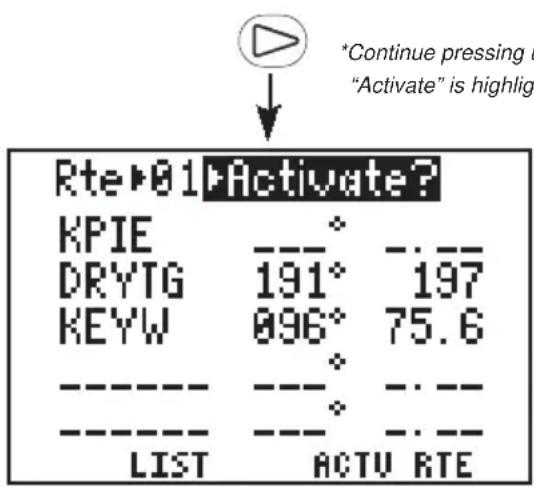
text_image
Rte▶01▶Activate? KPIE DRYTG 191° 197 KEYW 896° 75.6 ---- ---- ---- ---- LIST ACTU RTE *Continue pressing u "Activate" is highlightPress the right arrow key until "Activate?" is highlighted. (If "Activate?" is not displayed on this field, you may select it by pressing CLR.)
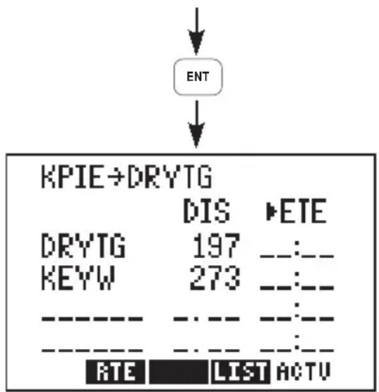
text_image
ENT KPIE→DRYTG DIS ►ETE DRYTG 197 -- KEYW 273 -- -- -- -- -- RTE LIST ACTUPress ENT to activate the route. The Active Route Page is displayed. This page displays the “active from” and “active to” waypoints on line one, as well as distance and time information to each waypoint on the following lines. The time information is blank since you are not moving yet.
Before you take off, you may want to view communications frequencies and
runway layout for St. Petersburg - Clearwater International.
To view airport information...
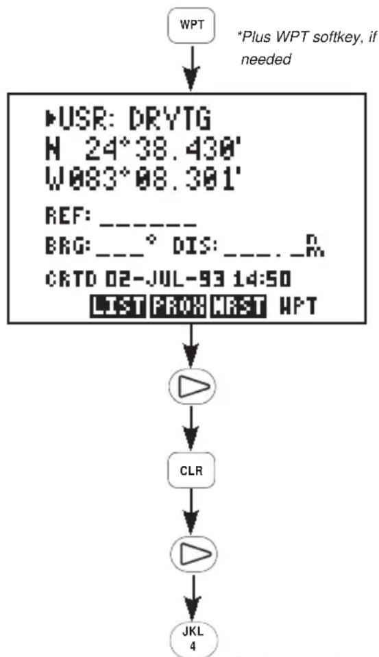
flowchart
graph TD
    A["WPT"] --> B["USB: DRYTG\nH 24°38.430'\nW083°08.301'\nREF: _\nBRG: __° DIS: ___. _R\nCRTD 02-JUL-93 14:50\nLIST PROH MAXT WPT"]
    B --> C["播放器"]
    C --> D["CLR"]
    D --> E["播放器"]
    E --> F["JKL\n4"]
    G["*Plus WPT softkey, if needed"] --> B
*Continue pressing the alphanumeric and arrow keys, if needed, to enter waypoint identifier
Press WPT and the WPT softkey, if needed, to select the Waypoint Definition Page.
Press the right arrow key to place the cursor on the waypoint category field.
Press CLR to select "APT", for airport.
Press the right arrow key to highlight the waypoint identifier field.
Enter the identifier for St. Petersburg - Clearwater International Airport (KPIE). Begin by pressing the "4" key to select the letter "K".
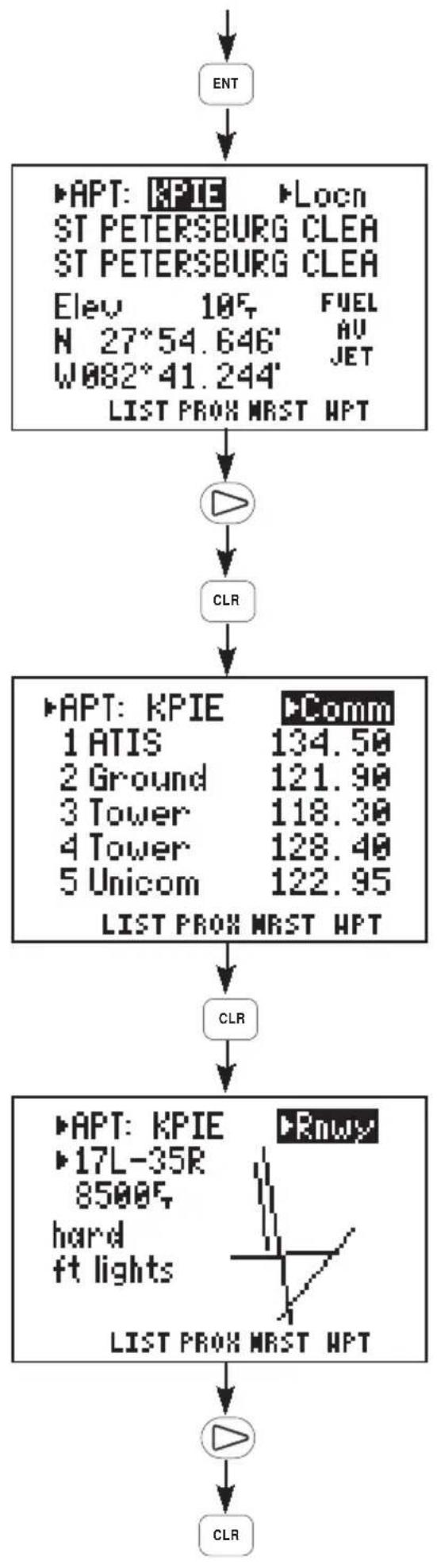
flowchart
graph TD
    A["ENT"] --> B["▶APT: KPIE ▶Locn\nST PETERSBURG CLEA\nST PETERSBURG CLEA\nElev 10F FUEL\nN 27°54.646' AU\nW082°41.244' JET\nLIST PROX MRST HPT"]
    B --> C["▶"]
    C --> D["CLR"]
    D --> E["▶APT: KPIE ▶Comm\n1 ATIS 134.50\n2 Ground 121.90\n3 Tower 118.30\n4 Tower 128.40\n5 Unicom 122.95\nLIST PROX MRST HPT"]
    E --> F["CLR"]
    F --> G["▶APT: KPIE ▶Rmwy\n17L-35R\n8500F hard\nft lights\nLIST PROX MRST HPT"]
    G --> H["▶"]
    H --> I["CLR"]
Continue pressing the alphanumeric and, if needed, arrow keys until the waypoint identifier has been entered. Press ENT when complete. Location information will be displayed for the airport (as well as available fuels).
Press the right arrow key.
Press CLR to view the communication frequencies.
Press CLR to view the runway information. A runway diagram is shown along with a cyclic field to view additional information about each runway: orientation, length, surface type, lighting.
Press the right arrow key to highlight the runway orientation field.
Press CLR to view additional runway information. You may continue pressing CLR to view all available runways.
In order to animate the GPS 95's displays you will need to enter a simulated speed.
To set the simulated speed...
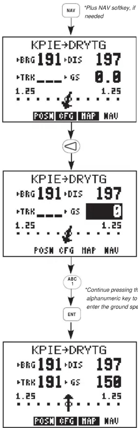
flowchart
graph TD
    A["NAV"] --> B["KPIE→DRYTG"]
    B --> C["POSN CFG MAP NAV"]
    C --> D["△"]
    D --> E["KPIE→DRYTG"]
    E --> F["POSN CFG MAP NAV"]
    F --> G["ABC 1"]
    G --> H["ENT"]
    H --> I["KPIE→DRYTG"]
    I --> J["POSN CFG MAP NAV"]
    J --> K["POSN CFG MAP NAV"]
    style B fill:#f9f,stroke:#333
    style E fill:#f9f,stroke:#333
    style I fill:#f9f,stroke:#333
Press NAV and the NAV softkey, if needed, to select the Navigation Summary Page.
Press the left arrow key to highlight the ground speed field.
Enter a ground speed of 150 knots. Begin by pressing the "1" key.
Continue pressing the alphanumeric keys until the ground speed has been entered. Press ENT when complete.
The simulation velocity is now set. The Navigation Summary Page will indicate distance, speed, track bearing and CDI information. Notice the distance is now decreasing as you fly towards the Dry Tortugas!
As your flight progresses, you can monitor the nearest airports at any time. This feature can be particularly valuable in the event of an in-flight emergency.
To view the nearest airports...
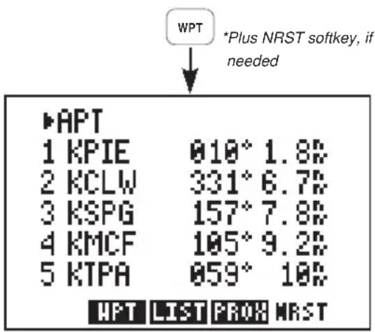
text_image
WPT *Plus NRST softkey, if needed APT 1 KPIE 010° 1.8% 2 KCLW 331° 6.7% 3 KSPG 157° 7.8% 4 KMCF 105° 9.2% 5 KTPA 059° 10% WPT LIST PROH NRSTPress the WPT key and the NRST softkey, if needed, to select the Nearest Waypoint Page.
The five nearest airports are instantly displayed along with bearing and distance to each airport.
In an actual emergency you could instantly plot a course to a nearest airport by highlighting the desired airport (using the arrow keys), pressing GOTO and ENT. The GPS 95 would override the route and provide navigation information to direct you to the selected airport.
Experiment with your GPS 95!
- Now that you have started on a trip to the Dry Tortugas, why don't you take some time to experiment with the GPS 95? Press each function key to get familiar with the available pages. Examine the Active Route Page and the Navigation Summary Page as the simulation progresses. If you want, change the simulator speed. You won't break the GPS 95 even if you enter a speed of 999 knots.
- As you progress through the simulation, the GPS 95 will alert you with a message when you are within one minute of reaching the Dry Tortugas. When passing DRYTG, the GPS 95 will automatically sequence to the next waypoint, KEYW.
- At some point during the simulation you may wish to try the GOTO function. Suppose severe weather was reported in the Dry Tortugas area. You wish to shorten your trip by heading directly to Key West. Simply press the GOTO key and enter KEYW. The GPS 95 will set an instantaneous course and you are on your way to Key West.
- If you have not customized your unit, this may be a good time to review Chapter 8 for information concerning custom settings. Doing so will help you understand what each setting will do.
- If you wish to stop the simulation, simply turn the GPS 95 off. We recommend that you delete the route and waypoint created in this simulation prior to using your unit again. (See Section 3.8 for information on deleting waypoints and Section 6.5 for information on deleting routes.)
APPENDIX A
MESSAGES
The GPS 95 uses the Message Page to communicate important information to you. Some messages are advisory in nature, others are warnings that may require your intervention. This appendix provides a complete list of messages and their meanings. Please pay careful attention to all messages.
Alarm Clock - The alarm time for the alarm clock has been reached.
Approaching ____ - You are less than one minute from reaching the indicated waypoint.
Arrival at ____ - Your craft has entered the arrival alarm circle for the indicated destination waypoint.
Battery Low - The battery pack is low on power. AA batteries should be replaced or the rechargeable battery pack should be recharged for continued operation.
Cannot nav lckd rte - An attempt has been made to activate a route containing a locked waypoint The GPS 95 cannot perform navigation in this situation.
Can't Chng Activ WPT - An attempt has been made to modify the position of the “active to” or “active from” waypoint. The GPS 95 will not allow the modifications.
CDI Alarm - Your course deviation has exceeded the limit that you specified on the Alarms/CDI Page.
Dbase Mem Failed - The GPS 95 has detected a failure in its flash memory when using the PC Database Update Kit. If this message occurs, the database is unusable and the unit should be taken to an authorized GARMIN service center.
Degraded Accuracy - The accuracy of the GPS 95 position is degraded beyond 500 meters due to satellite geometry or data quality. Additional cross checking should be performed by the user to verify the integrity of the GPS position.
Final altitude alert - The suggested VNAV altitude is within 1000 feet of the final altitude entered on the VNAV Page.
Leg Not Smoothed- The upcoming leg is too short for smooth waypoint transitions. Expect a rapid change in the CDI.
Memory Battery Low - The battery that sustains user memory is low and should be replaced by an authorized GARMIN service center as soon as possible. Failure to do so may result in loss of stored data, including all waypoints and routes.
Need Altitude - The GPS 95 needs altitude to start and/or continue 2D navigation. Press NAV and enter your current altitude. The altitude you enter should be as accurate as possible. An inaccurate altitude will result in an inaccurate position and navigation information.
No DGPS Position - An RTCM input has been selected, but not enough DGPS data is available to calculate a corrected position.
No RTCM Input - An RTCM input has been selected, but no data is being received or the input data is in the wrong format.
Osc Needs Adjustment - The GPS 95 has detected excessive drift in its internal crystal oscillator which may result in longer acquisition time. The unit should be taken to an authorized GARMIN service center as soon as possible.
Poor GPS Coverage - The GPS 95 cannot acquire sufficient satellites necessary to provide navigation.
Pwr Down and Re-init - The GPS 95 is unable to compute a position due to abnormal satellite conditions. Power down the unit and verify that the position on the Position Page is within a few degrees of your actual position.
Prox Alarm ____ - Your craft has penetrated the alarm circle of a proximity waypoint.
Proximity List Full - An attempt has been made to add more than nine waypoints to the proximity list. The GPS 95 will not allow more than nine proximity waypoints.
Proximity Overlap - The circles defined by two proximity waypoints overlay. When entering the area of the overlap, the GPS 95 will alert you of the closest proximity waypoint, but not both. You should be certain this condition is desirable.
Proximity Waypoint - An attempt has been made to delete a waypoint for which a proximity alarm has been defined. You must remove the waypoint from the proximity list before the waypoint can be deleted.
Proximity wpt lckd - At least one proximity waypoint is locked because the waypoint has been removed due to a database change.
Proximity wpt moved - One or more proximity waypoints were moved at least 0.33 arc minutes due to a database change.
Received Invalid Wpt - A waypoint was received in an upload/transfer operation that has an invalid identifier or position.
Receiver Failed - The GPS 95 has detected a failure in the receiver hardware. If the message persists, the GPS 95 is unusable and should be taken to an authorized GARMIN service center.
ROM Failed - The GPS 95 has detected a failure in its permanent memory. If this message occurs, the unit is unusable and should be taken to an authorized GARMIN service center.
Route is Full - An attempt has been made to add more than 30 waypoints to a route. The GPS 95 will not allow more than 30 waypoints per route.
Route Not Empty - An attempt has been made to copy a route to a non-empty route. The GPS 95 will not allow you to copy a route to a non-empty route.
Route Waypoint - An attempt has been made to delete a waypoint which is a member of one or more routes. You must remove the waypoint from all routes before the waypoint can be deleted.
Route Wpt Deleted - A waypoint in a transmitted route does not exist in the database and has been deleted from the route.
RTCM Input Failed - The GPS 95 was receiving RTCM inputs, but the data signal has been interrupted.
Searching the Sky - The GPS 95 is in the search-the-sky mode. Allow the unit to complete its data collection before turning it off. This process takes approximately 15 minutes.
Start altitude chng - The altitude change entered on the VNAV Page is about to begin.
Steep Turn Ahead - This message appears approximately one minute prior to a turn that requires a bank angle in excess of 25 degrees in order to stay on course.
Stored Data Lost - Stored user data, including waypoints, routes, and satellite orbital data has been lost due to a low memory battery.
Timer Expired - The count down timer has expired.
Track Memory Full - The track memory is full. Go to the Track Log Setup Page to clear the memory.
Transfer Completed - Data transfer operations are complete.
VNAV cancelled - The VNAV function has been cancelled due to a change in the active route.
WPT Exists ____ - You have entered a waypoint name on the AutoStore™ Page that already exists in memory. Enter a waypoint name that does not exist.
WPT Memory Full - The waypoint memory is full. You should delete unused waypoints to make room for new waypoints.
APPENDIX B
GLOSSARY AND NAVIGATION TERMS
B.1 DEFINITIONS
This section provides an illustration of and definitions for the terms used in this manual.
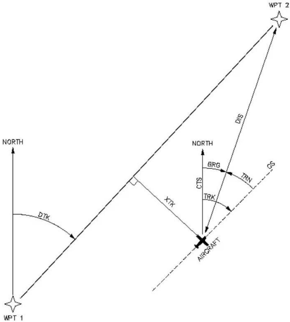
text_image
WPT 1 NORTH DTK XTR AIRGRAFT NORTH BRG CTS TRK DIS TRN G WPT 2Velocity/time terms:
GS Ground speed. GS is the speed measured relative to a ground position; also known as velocity over ground (VOG).
ETA Estimated time of arrival. ETA is the estimated time you will reach the “active to” waypoint based on current GS. This time is selectable as either UTC or local.
ETE Estimated time enroute. ETE is the time it will take to reach the “active to” waypoint based on current GS.
Direction terms:
DTK Desired track. DTK is the course between the “from” and “to” waypoints. In the case of the GOTO function, the “from” waypoint is the location at which the GOTO function was activated.
BRG Bearing. BRG is the direction from your present position to the "active to" waypoint.
CTS Course to steer. CTS is the recommended direction to steer in order to reduce cross track error and stay on course. (See Section B.2 for an example using CTS.)
TRK Track. TRK is the direction of movement relative to a ground position.
TRN Turn angle. TRN is the difference between BRG and TRK. "L" indicates you should turn to the left, "R" indicate you should turn to the right. The degrees indicate the angle you are off course.
Distance terms:
DIS Distance. DIS is the great circle distance from your position to the "active to" waypoint.
XTK Crosstrack. XTK is the cross track error, or distance that you are off course. If the crosstrack error exceeds the CDI scale setting, the XTK distance will also be displayed on the appropriate side of the CDI.
V VNAV altitude. V is the recommended altitude at which you should be in order to accomplish a VNAV maneuver. This information is only available when the VNAV function has been activated.
Satellite terms:
DOP Dilution of precision. DOP is a measure of the satellite geometry quality and hence the relative accuracy of your position (one meaning the best and ten meaning poor).
EPE Estimated position error. EPE, which is computed using the satellite geometry (DOP), signal and data quality, receiver tracking status and other factors, is an overall measure of your position accuracy.
B.2 COURSE TO STEER (CTS)
Course To Steer is a GARMIN exclusive that recommends an optimal direction to steer that will guide you to the course and proceed efficiently along your route.
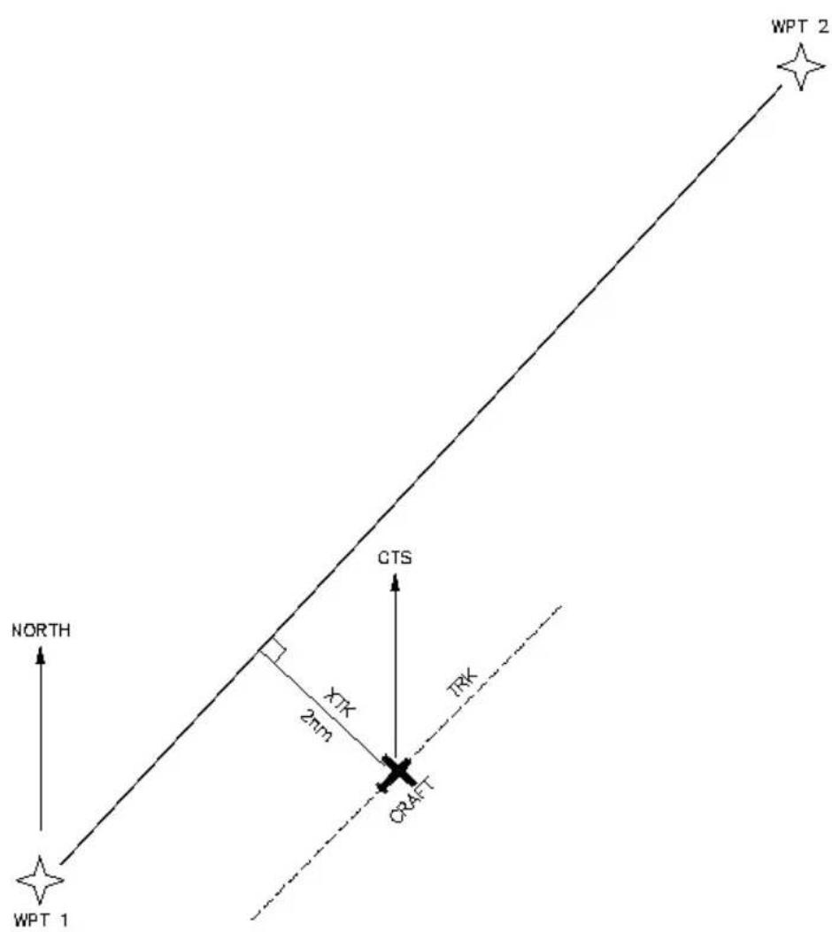
text_image
WPT 1 NORTH CTS XTK 2nm TRK CRAFT WPT 2As an example, suppose you activate the route illustrated above. The GPS
95 chooses the closest leg with a desired track of 45 degrees but your position happens to be two nautical miles off course. The unit will automatically compute the optimal course to steer (which is due north in this example). Press the NAV key until the Nav Summary Page is displayed, then select "CTS" on the first cyclic field. Using the CTS direction (000°), turn so that the track (TRK) and CTS direction match.
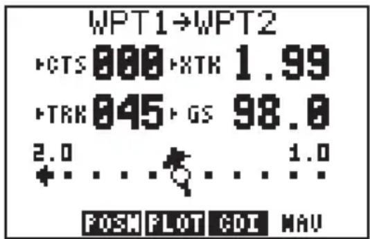
text_image
WPT1→WPT2 CTS 000 XTR 1.99 TRK 045 GS 98.0 2.0 ... 1.0 + . . . . . . . . . . . . . . . . . . . . . . . . . . . . . . . . . . . . . . . . . . . . . . . . . . . . . . . . . . . . . . . . . . . . . . FOSN PLOT CDI NAVAs you approach the course, CTS will slowly change and, once on course, will be identical to the desired track.
APPENDIX C
INSTALLATION AND MAINTENANCE
C.1 SPECIFICATIONS
GPS 95 SPECIFICATIONS*
PHYSICAL
Case: Waterproof
Size: Portable: 3.23"w x 6.26"h x 1.46"d
(82mm × 159mm × 37mm)
Fixed: 3.23"w x 4.87"h x 1.46"d
(82mm × 124mm × 37mm)
Weight: 14 ounces (0.4 kg) without battery pack 19
ounces (0.54 kg) with battery pack
POWER
Input Alkaline battery pack (4 AA size)
Rechargeable battery pack (Optional)
12 or 24 volt DC with power cable (5-40 VDC)
115 or 230 volt AC with A/C Adapter
Consumption 1.6 watts in Normal mode (without backlighting)
ENVIRONMENTAL
Temperature: -15°C to +70°C (+5°F to +158°F) operating
-40°C to +70°C (-40°F to +158°F) storage
Humidity: 95% non-condensing
PERFORMANCE
Receiver: MultiTrac
^TM , tracking up to 8 satellites
Frequency: L1, 1.57542 GHz
Acquisition Time: 2 minutes 2D
(typical) 2.5 minutes 3D
15 seconds Warm Start (with ephemeris)
Update Rate: Once per second, continuously
Accuracy: Position: 15 meters (49 ft) RMS **
Velocity: 0.1 knots RMS steady state
Dynamics: 999 knots velocity, 3g dynamics
INTERFACES
NMEA 0180
NMEA 0182
NMEA 0183 (Version 1.5; December 1987)
Approved sentences:
GPBWC, GPGLL, GPRMB, GPRMC, GPR00, GPWPL, GPXTE
Proprietary sentences:
PGRMZ
Transmission rate:
GPBWC, GPGLL, GPRMB, GPRMC, GPXTE, and PGRMZ transmitted once every two seconds.
GPR00 transmitted once every (# of all waypoints + 1) * 2 seconds. For example, if there are two route waypoints, this sentence will be transmitted once every six seconds.
GPWPL transmits all route waypoints in (# of route waypoints + 1) * 2 seconds. For example, if there are two route waypoints, this sentence will be transmitted twice every six seconds.
NOTES:
* All specifications are subject to change without notice.
** Subject to accuracy degradation to 100m 2DRMS under the United States Department of Defense imposed Selective Availability program. (Due to satellite geometry, altitude error is typically two to three times the horizontal position error.)
C.2 ELECTRICAL WIRING
The GPS 95 power/data cable allows you to connect the unit to vehicle power systems, other electronics, and a remote alarm/beeper. The power/data cable has a 7-pin intermediate connector to facilitate quick disconnection of all electrical connections and easy removal of the entire yoke mount from the aircraft. The GPS 95 is supplied with two wire harnesses: one with a cigarette lighter plug for temporary use and the other for permanent wiring. The figures below illustrate the two wiring options.
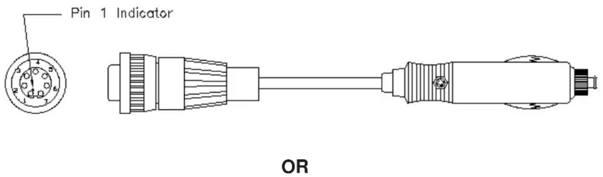
text_image
Pin 1 Indicator OR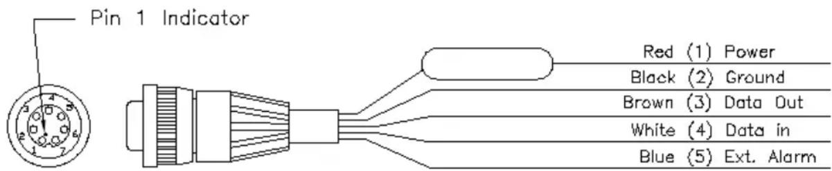
text_image
Pin 1 Indicator Red (1) Power Black (2) Ground Brown (3) Data Out White (4) Data in Blue (5) Ext. AlarmTo connect to vehicle power systems...
- Connect the RED harness lead (with fuse) to the positive (+) side of a 5-40 volt DC power source.
- Connect the BLACK harness lead to the negative (-) side of the 5-40 volt DC power source.
The GPS 95 will drive a remote alarm or relay that requires no more than 100 milliamps of current. (WARNING: Devices which draw current in excess of 100 milliamperes may damage your unit and will void your warranty. Consult the instructions included with the remote alarm or relay for current drain information.)
To connect to a remote alarm system...
- Connect the BLUE harness lead to the negative side of a transistor alarm or relay switch.
- Connect the positive side of the alarm or relay to the positive side of the 5-40 volt DC power source.
The GPS 95 may be connected to a PC-compatible computer using a NMEA 0183 data interface or to marine electronics such as an autopilot or plotter which use an NMEA 0180, NMEA 0182 or NMEA 0183 data interface. The unit can provide data for up to three NMEA “listeners” simultaneously. Refer to installation instructions of these devices for further information.
To connect the GPS 95 to an NMEA electronic device...
- Connect the BROWN harness lead to the NMEA “A” line of a two-wire, shielded cable.
- Connect the BLACK harness lead to the NMEA "B" line of the shielded cable.
- Connect the BLACK harness lead to the shield of the shielded cable. (The opposite end of the shield should not be grounded.)
C.3 YOKE MOUNT INSTALLATION
The GPS 95 is equipped with a yoke mount which can quickly be attached to the control yoke for easy access and visibility without blocking the view of the instrument panel. The yoke mount can quickly be detached and stowed in the carrying bag along with the GPS 95 radio and any other accessories you might wish to take with you. The clamp that comes with the standard yoke mount will fit the control yoke of more than 90% of general aviation aircraft. If the standard clamp will not fit your aircraft, call our toll-free product support number to exchange for the proper type of clamp for your aircraft. Generally, the standard clamp will not fit the following: Bonanza/Baron, Commanche, large Piper twins, and some other large Beech models.
The GPS 95 can also be fix mounted to a surface using the surface mount. Before permanent mounting, you may wish to apply power to the unit and look at the display in the desired mounting location to ensure you have the desired viewing angle.
To attach the yoke mount to the control yoke...
· Loosen the lower knob.
- Slide the clamp over the control yoke shaft just behind the control wheel.
- Tighten the lower knob securely.
- Make sure that the clamp is as close as possible to the control wheel and check to make sure that the yoke travel is not limited or hindered in any way by the yoke mount.
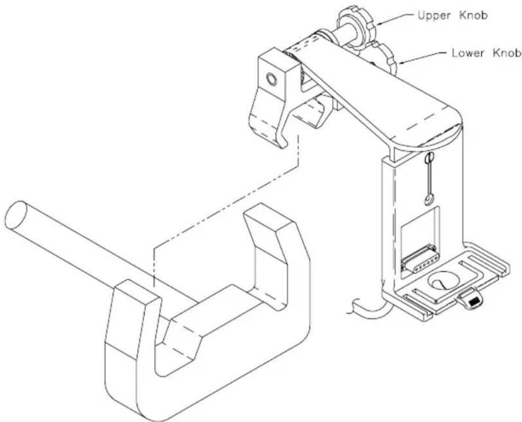
text_image
Upper Knob Lower KnobTo adjust the yoke mount viewing angle...
- Loosen the upper knob.
- Rotate the bracket up or down on the ratchet.
· Tighten the upper knob securely.
The yoke mount is designed to allow the GPS 95 to be installed either with or without the battery pack attached.
To adjust the yoke mount to accept the GPS 95 with the battery pack attached...
· Loosen the coinslot screw.
- Lower the cradle to its lowest position.
- Tighten the coinslot screw. When adjusted properly, the coinslot screw should fit completely into the counterbore in the cradle so that all surfaces are flush.
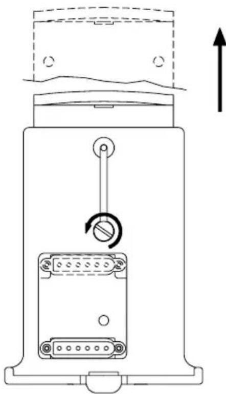
natural_image
Technical line drawing of a device with internal components and directional arrow (no text or symbols)The yoke mount has been designed for easy insertion and removal of your GPS 95 if you wish to use the unit in another airplane or vehicle, to plan at home, or to prevent theft.
To insert the GPS 95 into the yoke mount...
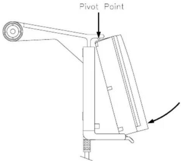
text_image
Pivot Point· Tilt the top of the GPS 95 into the yoke mount as shown.
- Engage the slot in the top of the GPS 95 into the raised bump in the yoke mount bracket.
- Rotate the bottom of the GPS 95 into the yoke mount until the unit latches securely into place.
- Connect the antenna or antenna cable. No other electrical connections are required; all power and data connections are made through the 6-pin connector mounted in the yoke mount bracket.
To remove the GPS 95 from the yoke mount...
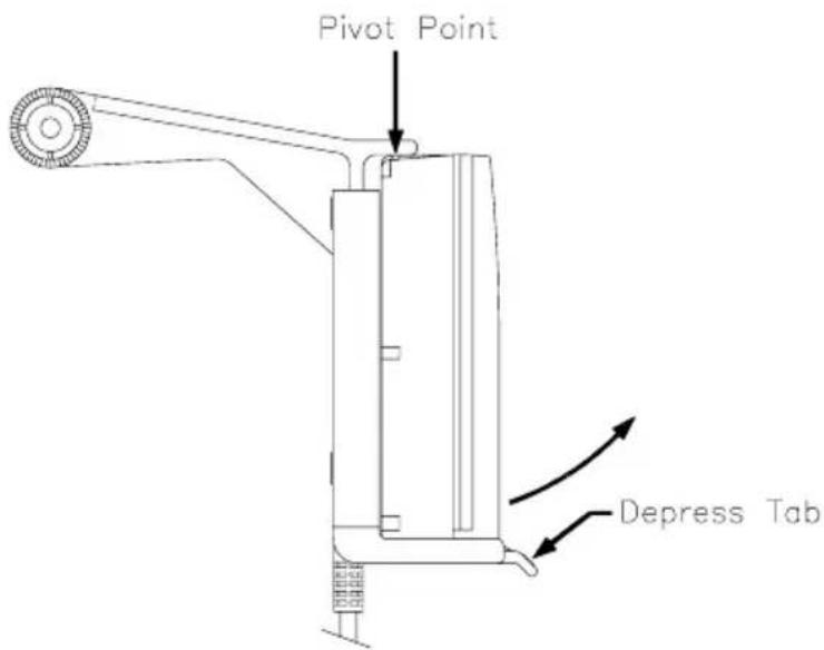
text_image
Pivot Point Depress Tab- Disconnect the antenna or antenna cable.
- Apply enough force to the release tab to allow the unit to pass as shown above.
- Pull the bottom of the GPS 95 out. Then rotate the top downward and out.
NOTE: The portable antenna is removed by gripping the antenna at its base (on the knurled knob) and rotating 1/4 turn counterclockwise. The antenna will then pull straight off of the BNC connector on the side of the unit
C.5 PORTABLE ANTENNA INSTALLATION
The GPS 95 is supplied with a portable antenna mount that allows the antenna to be affixed to a windshield or any smooth surface using a suction cup mount and a six foot extension cable. As an alternative, the suction cup can be removed and replaced with the plastic shoulder washer and self-threading screw to permanently attach the mounting bracket to the glare shield.
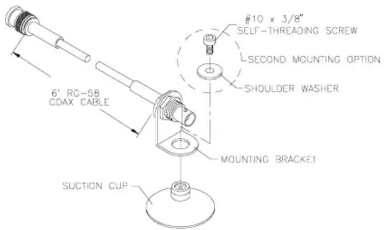
text_image
6' RG-58 COAX CABLE MOUNTING BRACKET SUCTION CUP #10 x 3/8" SELF-THREADING SCREW L-SECOND MOUNTING OPTION SHOULDER WASHERThe GPS 95 is supplied with a sealed, 4-cell alkaline battery pack. The battery pack must be removed from the unit in order to replace the cells.
To remove the battery pack...
- Push down on the spring tab on the right side of the battery pack.
- Pull the battery pack off the right side of the unit.
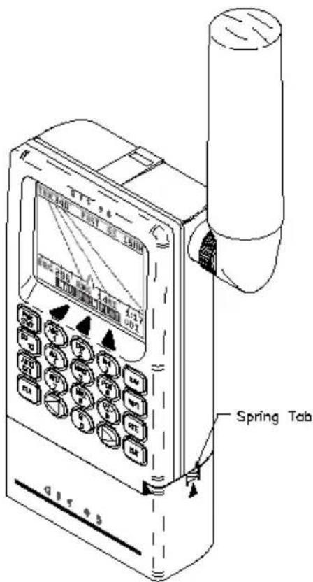
text_image
Spring TabTo replace the alkaline batteries...
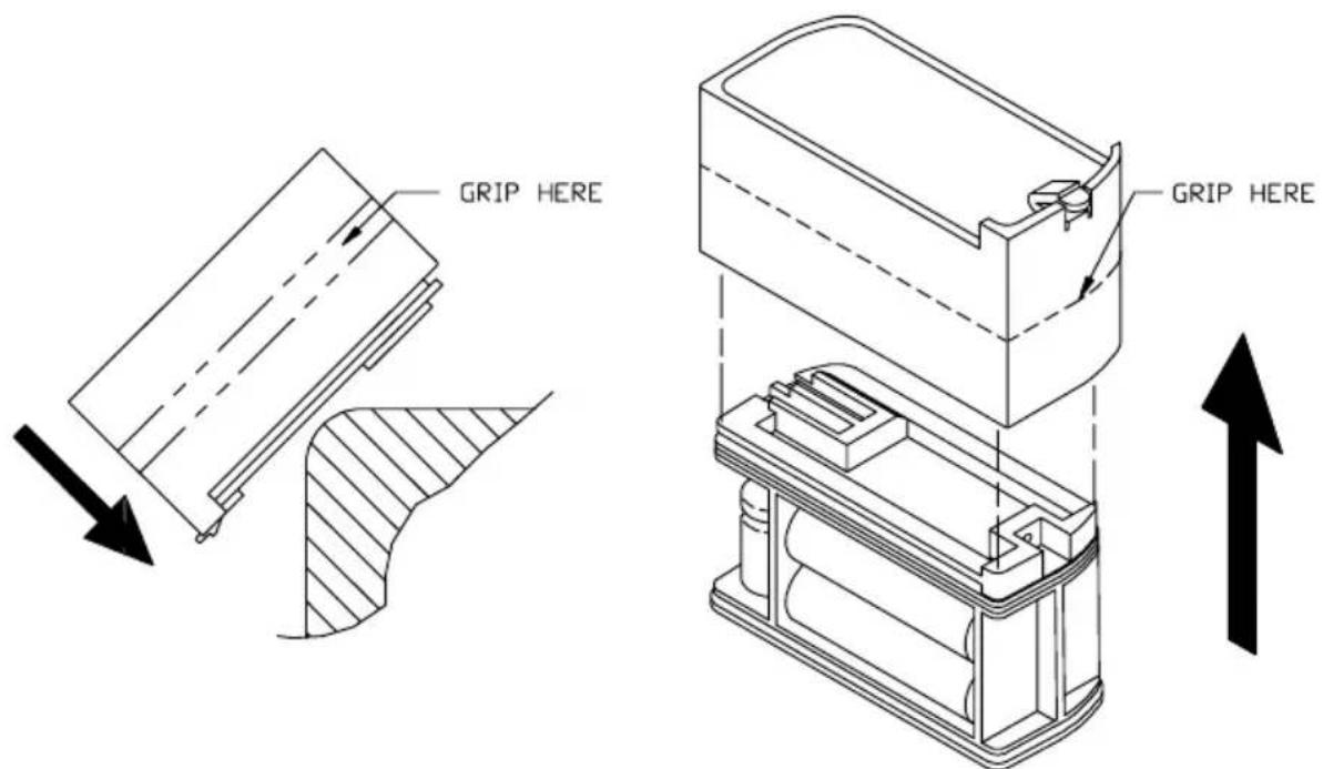
text_image
GRIP HERE GRIP HERE· Grip the battery pack around the outside edge (not the bottom).
- Push the top of the battery pack against the edge of a hard surface which will not mar the plastic. The outer sleeve will slide off the cage, revealing the batteries inside.
- Replace the batteries, observing the polarity diagram engraved in the plastic.
- Slide the sleeve over the cage until it snaps into place, taking care that you do not tear the gaskets which seal the battery pack.
C.7 MAINTENANCE
The GPS 95 is constructed of high quality material and should not require user maintenance. Please refer any repairs to an authorized GARMIN service center. (The unit contains no user serviceable parts. Do not attempt repairs yourself.)
Never allow gasoline or solvents to come into contact with your unit. Damage to the case may occur which is not covered by your warranty.
The waypoints, routes, custom settings and other data stored in the GPS 95 are maintained by an internal battery. (This data will not be lost even if you remove the AA or rechargeable battery pack for separate storage.) The internal memory battery should typically last three to five years. If the GPS 95 detects a low memory battery, you will be informed with the message "Memory Battery Low". You should return your unit to an authorized GARMIN service center as soon as possible for service. Failure to do so may result in loss of data each time you turn your unit off (indicated by the message "Stored Data Lost").
Your GPS 95 contains a highly accurate crystal oscillator which should provide many years of reliable operation. If the unit detects excessive oscillator drift, you will be informed with the message “Osc Needs Adjustment”. You should return your unit to an authorized GARMIN service center as soon as possible. Failure to do so may result in degraded acquisition performance.
C.8 PRODUCT SUPPORT
Should you require additional assistance, please call our Product Support Department. Customers in the continental United States may use our toll free number: 1-800-800-1020. Customers outside the continental United States may call 1-913-599-1515. Please note the software version of your unit as indicated on the welcome page when the unit is first turned on. Also, please have the serial number for your unit available.
APPENDIX D
MAP DATUMS
The following is a list of the GPS 95 map datum selections and the corresponding map datum name (including the area of application):
Adindan Adindan - Ethiopia, Mali, Senegal, Sudan
Afgooye Afgooye - Somalia
ARC 1960 ARC 1960 - Kenya, Tanzania
Ascension Island '58 Ascension Island '58 - Ascension Island
Astro B4 Sorol Atoll Astro B4 Sorol Atoll - Tern Island
Astro Beacon "E" Astro Beacon "E" - Iwo Jima Island
Astro Dos 71/4 Astro Dos 71/4 - St. Helena Island
Astronomic Stn '52 Astronomic Stn '52 - Marcus Island
Australian Geod '66 Australian Geod '66 - Australia, Tasmania Island
Australian Geod '84 Australian Geod '84 - Australia, Tasmania Island
Bellevue (IGN) Bellevue (IGN) - Efate and Erromango Islands
Bermuda 1957 Bermuda 1957 - Bermuda Islands
Bogota Obsrvatry Bogota Obsrvatry - Colombia
Campo Inchauspe Campo Inchauspe - Argentina
Canto Astro 1966 Canto Astro 1966 - Phoenix Islands
Cape Cape - South Africa
Cape Canaveral Cape Canaveral - Florida, Bahama Islands
Carthage Carthage - Tunisia
CH-1903 CH-1903 - Switzerland
Chatham 1971 Chatham 1971 - Chatham Island (New Zealand)
Chua Astro Chua Astro - Paraguay
Corrego Alegre Corrego Alegre - Brazil
Djakarta (Batavia) Djakarta (Batavia) - Sumatra Island (Indonesia)
Dos 1968 Dos 1968 - Gizo Island (New Georgia Islands)
Easter Island 1967 Easter Island 1967 - Easter Island
European 1950 European 1950 - Austria, Belgium, Denmark, Finland,
France, Germany, Gibraltar, Greece, Italy, Luxembourg,
Netherlands, Norway, Portugal, Spain, Sweden, Switzerland
European 1979 European 1979 - Austria, Finland, Netherlands, Norway,
Spain, Sweden, Switzerland
Finland Hayford Finland Hayford - Finland
Gandajika Base Gandajika Base - Republic of Maldives
Geodetic Datum '49 Geodetic Datum '49 - New Zealand
Guam 1963 Guam 1963 - Guam Island
Gux 1 Astro Gux 1 Astro - Guadalcanal Island
Hjorsey 1955 Hjorsey 1955 - Iceland
Hong Kong 1963 Hong Kong 1963 - Hong Kong
Indian Bangladesh Indian - Bangladesh, India, Nepal
Indian Thailand Indian - Thailand, Vietnam
Ireland 1965 Ireland 1965 - Ireland
ISTS 073 ASTRO '69 ISTS O73 ASTRO '69 - Diego Garcia
Johnston Island Johnston Island - Johnston Island
Kandawala Kandawala - Sri Lanka
Kergulen Island Kergulen Island - Kerguelen Island
Kertau 1948 Kertau 1948 - West Malaysia, Singapore
L.C. 5 Astro L.C. 5 Astro - Cayman Brac Island
Liberia 1964 Liberia 1964 - Liberia
Luzon Mindanao Luzon - Mindanao Island
Luzon Philippines Luzon - Phillippines (excluding Mindanao Island)
Mahe 1971 Mahe 1971 - Mahe Island
Marco Astro Marco Astro - Salvage Islands
Massawa Massawa - Eritrea (Ethiopia)
Merchich Merchich - Morocco
Midway Astro 1961 Midway Astro 1961 - Midway Island
Minna Minna - Nigeria
NAD27 Alaska NORTH AMERICAN 1927 - Alaska
NAD27 Bahamas NORTH AMERICAN 1927 - Bahamas (excluding San
Salvador Island)
NAD27 Canada NORTH AMERICAN 1927 - Canada (including
Newfoundland Island)
NAD27 Canal Zone NORTH AMERICAN 1927 - Canal Zone
NAD27 Caribbean NORTH AMERICAN 1927 - Caribbean (Barbados, Caicos
Islands, Cuba, Dominican Republic, Grand Cayman,
Jamaica, Leeward Islands, Turks Islands)
NAD27 Central NORTH AMERICAN 1927 - Central America (Belize,
Costa Rica, El Salvador, Guatemala, Honduras, Nicaragua)
NAD27 CONUS NORTH AMERICAN 1927 - Mean Value (CONUS)
NAD27 Cuba NORTH AMERICAN 1927 - Cuba
NAD27 Greenland NORTH AMERICAN 1927 - Greenland (Hayes Peninsula)
NAD27 Mexico NORTH AMERICAN 1927 - Mexico
NAD27 San Salvador NORTH AMERICAN 1927 - San Salvador Island
NAD83 NORTH AMERICAN 1983 - Alaska, Canada, Central
America, CONUS, Mexico
Nahrwn Masirah lInd Nahrwn - Masirah Island (Oman)
Nahrwn Saudi Arabia Nahrwn - Saudi Arabia
Nahrwn United Arab Nahrwn - United Arab Emirates
Naparima BWI Naparima BWI - Trinidad and Tobago
Observatorio 1966 Observatorio 1966 - Corvo and Flores Islands (Azores)
Old Egyptian Old Egyptian - Egypt
Old Hawaiian Old Hawaiian - Mean Value
Oman Oman - Oman
Ord Srvy Grt Britn Ord Srvy Grt Britn - England, Isle of Man, Scotland,
Shetland Islands, Wales
Pico De Las Nieves Pico De Las Nieves - Canary Islands
Pitcairn Astro 1967 Pitcairn Astro 1967 - Pitcairn Island
Prov So Amricn '56 Prov So Amricn '56 - Bolivia, Chile,
Colombia, Ecuador, Guyana, Peru, Venezuela
Prov So Chilean '63 Prov So Chilean '63 - South Chile
Puerto Rico
Puerto Rico - Puerto Rico, Virgin Islands
Qatar National
Qatar National - Qatar
Qornoq
Qornoq - South Greenland
Reunion
Reunion - Mascarene Island
Rome 1940
Rome 1940 - Sardinia Island
RT 90 SWEDEN
Santo (Dos)
Santo (Dos) - Espirito Santo Island
Sao Braz
Sao Braz - Sao Miguel, Santa Maria Islands (Azores)
Sapper Hill 1943
Sapper Hill 1943 - East Falkland Island
Schwarzeck
Schwarzeck - Namibia
South American '69 South American '69 - Argentina, Bolivia, Brazil, Chile,
Colombia, Ecuador, Guyana, Paraguay, Peru, Venezuela, Trinidad and Tobago
South Asia
South Asia - Singapore
Southeast Base
Southeast Base - Porto Santo and Madeira Islands
Southwest Base
Southwest Base - Faial, Graciosa, Pico, Sao Jorge, and Terceira Islands (Azores)
Timbalai 1948
Timbalai 1948 - Brunei and East Malaysia (Sarawak and Sabah)
Tokyo Tokyo - Japan, Korea, Okinawa
Tristan Astro 1968
Tristan Astro 1968 - Tristan da Cunha
Viti Levu 1916
Viti Levu 1916 - Viti Levu Island (Fiji Islands)
Wake-Eniwetok '60 Wake-Eniwetok '60 - Marshall Islands
WGS 72
WORLD GEODETIC SYSTEM 1972
WGS 84
WORLD GEODETIC SYSTEM 1984
Zanderij
Zanderij - Surinam
APPENDIX E
UTC TIME TO LOCAL TIME OFFSET
Reference the chart below to find the UTC-to-local time offset for your longitude zone. (If you are in a daylight savings time zone, add one hour to the offset.) For example, if you are at longitude W081°00.00' and UTC time is 16:00, local time is 11:00 standard time.
Longitude Zone Offset
| W180.0° to W172.5° - 12 |
| W172.5° to W157.5° - 11 |
| W157.5° to W142.5° - 10 |
| W142.5° to W127.5° - 9 |
| W127.5° to W112.5° - 8 |
| W112.5° to W097.5° - 7 |
| W097.5° to W082.5° - 6 |
| W082.5° to W067.5° - 5 |
| W067.5° to W052.5 - 4 |
| W052.5° to W037.5° - 3 |
| W037.5° to W022.5° - 2 |
| W022.5° to W007.5° - 1 |
| W007.5° to E007.5° 0 |
| E007.5° to E022.5° + 1 |
| E022.5° to E037.5° + 2 |
| E037.5° to E052.5° + 3 |
| E052.5° to E067.5° + 4 |
| E067.5° to E082.5° + 5 |
| E082.5° to E097.5° + 6 |
| E097.5° to E112.5° + 7 |
| E112.5° to E127.5° + 8 |
| E127.5° to E142.5° + 9 |
| E142.5° to E157.5° +10 |
| E157.5° to E172.5° +11 |
| E172.5° to E180.0° +12 |
NOTE: The time zone boundaries given above may be different depending on your area. Consult your charts for more accurate information concerning time zones.
APPENDIX F
INDEX
A
Active from waypoint 6-1
Active leg 6-1
Active Route Page 6-5
Active to waypoint 6-1
Airport communication information 3-5
Airport information 3-3
Airport location information 3-5
Airport runway information 3-5
Alarm clock 8-9
Alarms/CDI Page 8-8
Alphanumeric field 2-2
Alphanumeric keys 2-3
Altitude, entering 5-6
Antenna, installing C-8
Antenna, removing C-8
Arrival alarm 8-9
Arrow keys 2-3
Audio/Display Page 8-11
Audio tones 8-11
AutoLocate™ 2-6
AUTOSTOre Key 2-3
AutoStore™ Page 7-1
AutoStore™, routes 7-2
AutoStore™, waypoints 7-1
Auxiliary Menu 8-4
B
Backlighting time-out 8-12
Bar field 2-2
Bar Graph Display 8-2
Basic package 1-3
Battery pack, operation C-8
Battery Saver mode 1-5
Bearing (BRG) B-2
C
Capabilities 1-1
CDI alarm 8-8
CDI orientation 8-9
CDI scale 8-9
CLR Key 2-3
Communication frequencies 3-5
Confirmation field 2-2
Contrast, display 8-11
Course Deviation Indicator (CDI) 5-2
Course to steer (CTS) B-2
Crosstrack error B-2
Cursor 2-2
Cyclic field 2-2
D
Data, entering 2-4
Database, aviation 1-2
Database contents 1-2
Database Page 2-6
Date/Time Page 8-10
Density altitude 8-15
Desired track (DTK) B-2
Differential GPS (DGPS) 8-13
Dilution of precision (DOP) B-3
Display contrast 8-11
Distance to waypoint (DIS) B-2
DTK up 5-6
E
E6-B calculations 8-4
ENT Key 2-3
Entering data 2-4
Estimated position error (EPE) B-3
©
Proximity alarm waypoints 3-17
Proximity Waypoint Page 3-17
PWR/STAT Key 2-2
R
Receiver status messages 8-2
Rechargeable NiCad battery 1-4
Relative bearing pointer 5-2
Reviewing waypoints 3-16
Route Definition Page 6-2
Route List Page 6-6
Routes 6-1
activating 6-4
copying 6-3
creating 6-3
deleting 6-5
editing 6-4
inverting 6-4
RTCM input 8-13
RTE Key 2-3
Runway configuration 3-6
Runway information 3-5
Runway length, minimum 8-5
Runway lighting 3-6
Runway surface, desired 8-5
Runway surfaces 3-6
S
Satellite Skyview Page 8-4
Satellite Status Page 8-3
Scale, map 5-4
Scanning waypoints 3-14
Setups, unit 8-4
Simulator mode 1-5
Softkeys 2-1
Specifications C-1
Steer to, orientation 8-9
Sunrise/Sunset Page 8-16
Surface, runway 3-6
T
3D Navigation 2-7
Timer, count down 8-11
Timer, count up 8-10
Time-out, backlighting 8-12
Track (TRK) B-2
Track Log Setup Page 8-6
Trip and Fuel Planning Page 8-17
Trip planning, routes 8-18
Trip planning, waypoints 8-17
TRK up 5-6
Trueairspeed 8-15
Turn angle (TRN) B-2
Turning off 2-7
Turning on 2-5
2D Navigation 2-7
U
Units/Heading Page 8-7
Units, selecting 8-7
User map datum 8-14
User waypoint information 3-9
User waypoints creating 3-10
deleting 3-12
renaming 3-13
Using waypoints 3-13
UTC time 8-10
V
VNAV, activating 8-19
VNAV altitude (V) B-2
Vertical navigation (VNAV) 8-18
Vertical speed, calculating 8-19
Viewing messages 2-5
VOR information 3-6
W
Waypoint categories 3-2
Waypoint Definition Page 3-1
Waypoint List Page 3-12
Waypoints 3-1
nearest 3-18
reviewing 3-16
scanning 3-14
using 3-13
Winds aloft 8-15
Wiring, electrical C-3
WPT Key 2-3
Y
Yoke mount, installation C-4
Yoke mount, operation C-6
Z
Zero Key 2-3

GARMIN ^SM
GARMIN International, Inc.
9875 Widmer Road
Lenexa, KS 66215
1-800-800-1020
(913) 599-1515