Apollo GX 50 - Gps GARMIN - Free user manual and instructions
Find the device manual for free Apollo GX 50 GARMIN in PDF.

User questions about Apollo GX 50 GARMIN
0 question about this device. Answer the ones you know or ask your own.
Ask a new question about this device
Download the instructions for your Gps in PDF format for free! Find your manual Apollo GX 50 - GARMIN and take your electronic device back in hand. On this page are published all the documents necessary for the use of your device. Apollo GX 50 by GARMIN.
USER MANUAL Apollo GX 50 GARMIN
No part of this document may be reproduced in any form or by any means without the express written consent of Garmin AT, Inc.
II Morrow, Garmin AT, Inc., and Apollo are trademarks of Garmin AT, Inc. © 2003 by Garmin AT, Inc. All rights reserved. Printed in the U.S.A.
Garmin AT, Inc. Consumer Products Division 2345 Turner Road, S.E. Salem, OR 97302
U.S.A. Toll Free 800.525.6726 Canada Toll Free 800.654.3415 International 503.391.3411 FAX 503.364.2138
Visit our web page at http://www.garminat.com Send comments about this manual by email to: techpubs@garminat.com

GARMIN®
Welcome ...
Welcome to a new era of aviation navigation. Once again, Garmin AT, Inc. has set new standards in features and ease of use for the general aviation public. The Apollo GX-series of products are unequaled in providing the features, level of performance, and reliability that aviation users require. The Apollo GX-series sets a precedent that will be the standard to which all other avionics will be compared.
The Apollo GX50 is a full-featured GPS receiver that is IFR-certified for non-precision approach. The GX55 GPS receiver is IFR-certified for en route operation and designed to slide into your existing Apollo Loran or Flybuddy GPS receiver mounting tube. The GX60 combines the features of the GX50 with a revolutionary comm radio. The GX65 has the comm features of the GX60, but is not IFR approach certified and does not have the approach features.
You can be confident in knowing that you are the owner of the state-of-the-art in aviation navigation and communication. Our products are built to last and to satisfy your navigation needs.
Read the Introduction and Getting Started sections of the User's Guide before you use your Apollo GX; these sections will give you the “rules of the road.” You can then refer to the other sections as a reference for the power you have at your fingertips with the most comprehensive navigation equipment available.
You will note that your User's Guide may be missing some sections. This guide serves the entire family of Apollo GX products, but will only include the sections that reflect the features available in the product that you purchased. If you have an interest in the features and operation of the other models, see the section on Ordering Information.
History of Revisions
Revision Date Software Ver. Manual P/N
January 1998 2.1 560-0961-00
June 1998 2.2 560-0961-01
January 1999 2.2 560-0961-01a
March 1999 3.0 560-0961-02
July 2001 3.3 560-0961-03
November 2001 3.4 560-0961-03a
August 2003 3.4 560-0961-03b
Ordering Information
To receive additional copies of the Apollo GX50/55/60/65 manuals order the following part numbers:
User's Guide 560-0961-xx
Approach User's Guide Insert 560-0928-xx
GX60/65 Comm User's Guide Insert 560-0963-xx
User's Guide Binder (1") 560-9000
User's Guide Binder (3/4") 560-9002
User's Guide Binder (1-1/4") 560-9008
User's Guide Binder (1-1/2") 560-9005
GX50/60/65 Installation Manual 560-0959-xx
GX50/60/65 SW Ver 3.3 Installation Manual
Upgrade Supplement 561-0275-xx
A-33 Antenna Installation Guide 560-0949-xx
GX55 Installation Manual 560-0960-xx
GX50 Quick Reference 561-0238-xx
GX55 Quick Reference 561-0237-xx
GX60/65 Quick Reference 561-0236-xx
GX65 User's Guide Insert 561-0256-xx
GX60/65 Comm User's Guide Insert 561-xxxx-xx
Important Notice
The Global Positioning System (GPS) is operated by the United States Department of Defense which is solely responsible for the accuracy, daily operation, and maintenance of the satellite constellation. System accuracy is affected by the Department of Defense's Selective Availability (SA) and the Dilution of Precision (DOP) attributed to poor satellite geometry.
Due to implementation of Selective Availability by the United States Department of Defense (DoD), all GPS receivers may suffer degradation of position accuracy. The DoD has stated that 95% of the time horizontal accuracy will not be degraded more than 100 m and 99.9% of the time accuracy will not be degraded more than 300 m.
Installations of TSO C-129a authorized Apollo GX50/60's and TSO-C-129 authorized GX55's may be approved for supplemental navigation only. The Apollo GX50, GX55, or GX60 may be used as the primary navigation data display, however, other means of navigation appropriate to the intended route of flight must be installed and operational. It is not required that these other systems be monitored.
FCC Notice
This equipment has been tested and found to comply with the limits for a Class B digital device, pursuant to part 15 of the FCC Rules. These limits are designed to provide reasonable protection against harmful interference during residential use. Operation is subject to the following two conditions: (1) this device may not cause harmful interference, and (2) this device must accept any interference received, including interference that may cause undesired operation. This equipment generates, uses and can radiate radio frequency energy and, if not installed and used in accordance with the instructions, may cause harmful interference to radio communications. However, there is no guarantee that interference will not occur in a particular installation. If this equipment does cause harmful interference to radio or television reception, which can be determined by turning the equipment off and on, the user is encouraged to try to correct the interference by one or more of the following measures:
• Reorient or relocate the receiving antenna.
- Increase the separation between the equipment and receiver.
- Connect the equipment into an outlet on a circuit different from the one the receiver is connected.
- Consult the dealer or an experienced radio/TV technician for help.
Changes or modifications to this equipment not expressly approved by Garmin AT, Inc. could void the user's authority to operate this equipment.
Canadian Notice
This Class B digital apparatus meets all requirements of the Canadian Interference-Causing Equipment Regulations.
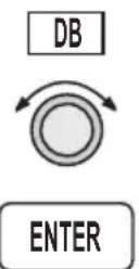
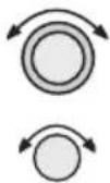
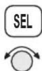
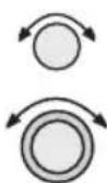
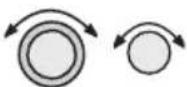
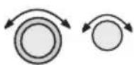
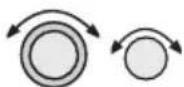
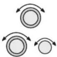
The SMALL knob is the smaller, inner knob of the two concentric rotary knobs used to look at or change information on the display. When only the SMALL knob is shown next to an example, turn the SMALL knob.
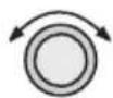
The LARGE knob is the larger, outer knob of the two concentric rotary knobs used to look at or change information on the display. The LARGE knob graphic shows both of the concentric knobs. Turn the LARGE, outer knob when this graphic is shown next to an example.
ENTER
Text in all caps and bold indicates the key to press.
A graphic key on the side of the page refers to the key you should press for the given example. There are two types of keys: hard keys and smart keys.

A “hard” key is a permanent key on the right side of the front panel. The NAV key example shown here is a “hard” key.

The “smart” keys are five small keys below the display. The key label is shown above the key on the display and may change depending on the function you are using. Press the key below the label to access the function.
Text in a display example with an underline indicates the text will flash. In the example below, the field labeled “01:23” is underlined to indicate that it is flashing and ready for editing. The flashing characters on the display are changed by turning the SMALL knob. The GX55 is shown below as an example for

text_image
the control locations Flashing Hard Keys Power Large, Outer Knob GPS ETE SLE 01:23 1.006 Bkg 126 123Nm MSG DB FPL SYS APOLLO GX55 OFF-ON NAV NRST INFO SEL MAP -D ENTER Smart Key Annunclator Smart Keys Small, Inner KnobTable of Contents
Introduction 1 - 1
Apollo GX Features 1-1
Display 1 - 2
External Annunciators....1 - 3
Controls....1 - 3
Keys 1 - 4
Hard Keys 1 - 4
"Smart" Keys 1-5
Map Function Smart Keys 1-6
Communications Radio Mode Smart Keys (GX60/65) ..... 1-8
Apollo GX Features 1-9
Getting Started....2-1
Power On 2 - 1
Select a Waypoint....2-1
Finding a waypoint by name 2-1
Sorting waypoints by selected characters....2-2
Looking at all waypoints in a database 2-3
Duplicate Identifier, City, or Facility Names....2-4
Waypoint Information....2 - 4
Storing a Waypoint 2-5
Finding a Nearest Waypoint....2-6
Flying Direct-To a Waypoint....2-7
Create a Flight Plan....2-8
Activating a Flight Plan....2-9
Using the Moving Map 2-10
Navigation Basics 3 - 1
About the Navigation Function 3-1
About the Navigation Function Displays .... 3-1
Nav Home Page....3-1
Autonav....3-2
Relative Bearing Indicator....3-3
Nav Pages 3 - 3
Estimated Time En Route (Ete) 3-4
Bearing (Brg) 3 - 4
Table of Contents
Range (Rge) 3 - 4
Course Deviation Indicator (CDI) and Distance Off Track. 3-5
TO/FROM Indicator 3 - 6
Desired Track (Dtk) 3-6
Leg (FROM-TO) Distance 3-6
Track (Trk) Angle....3-7
Track Angle Error (Tae)....3-7
Ground Speed (GS) 3-7
Minimum Safe Altitude (MSA)....3-8
Minimum En Route Safe Altitude (MESA)....3-8
Flight Time 3 - 9
Time UTC 3-9
Estimated Time of Arrival (ETA) 3-9
Nearest Waypoint & Airspace Search....3-9
Controlled Special Use Airspace....3-13
Altitude Assist (VNAV) 3-14
Parallel Track Offset 3-19
GPS Position 3-21
Countdown Timer 3-22
Arc Assist 3-23
Waypoint Distance Page 3-25
Waypoint ETE Page 3-25
From-To-Next Waypoint ETA Page....3-25
From/To/Next Waypoint....3-26
Creating FROM/TO/NEXT Waypoints .... 3-26
Placing the TO Waypoint on Hold....3-30
Using Direct-To....3-31
Direct-To Examples....3-32
Center the CDI 3-32
Enter a New Waypoint into a Flight Plan .... 3-33
Direct-To OBS. 3-35
Turn Anticipation 3-36
Standard Turn Operation....3-36
Wind and Turn Anticipation 3-37
GPSS 3-37
Standard GPSS Operation....3-37
Table of Contents
Approach GPSS Operation 3-38
GPSS Rules 3-38
Tuned Station....3-39
Tuning to a VOR....3-39
Tuning to a Localizer 3-40
Moving Map Functions 4-1
Full Screen Map....4-1
Controls. 4 - 2
Waypoint Type Keys....4-2
Waypoint List Keys 4-2
Waypoint Scan Key....4-3
Map Scale....4 - 3
Map and Nav Info 4-3
Map Setup. 4 - 4
Route Line....4 - 4
Map Orient. 4 - 5
Map Reference 4 - 6
Identifier and Waypoint Type Selection....4-6
Track History....4 - 8
Airspace Setup 4-10
Airspace Buffers 4-11
ATC Ring Selection 4-12
Airspace Selections 4-12
Search and Rescue 4-14
Search and Rescue Map Description....4-14
Grid Line Display 4-15
US Grid Type 4-15
Basic Grid Type....4-16
Search and Rescue Map Setup Page 4-16
Set the SAR Position (Basic Grid Type) 4-18
Selecting A Pattern 4-20
Parallel Line Search Pattern....4-21
Creeping Line Search Pattern 4-23
Expanding Square Search Pattern....4-26
Mark A Position....4-28
Create A User Waypoint By US Grid 4-29
Table of Contents
Fly Direct To A US Grid 4-30
Create a User Waypoint By Basic Grid....4-30
Fly Direct To A Basic Grid....4-32
Setting Up A Search Pattern. 4-32
Waypoint Database....5 - 1
Waypoint Information....5-1
Available Waypoint Information 5-1
Getting Information About A Waypoint ..... 5-3
Airport Info Pages 5-5
Create User Waypoint by Lat/Lon 5-9
Create User Waypoint by Radial/Distance ..... 5-10
Update User Wpt with Present Pos 5-12
Delete User Waypoint 5-12
Modify User Waypoint 5-13
Creating Waypoint Comments....5-14
Deleting Waypoint Comments....5-15
Update User Waypoint 5-16
Datacard 5-16
RNAV Waypoints. 5-16
Flight Plan Functions 6-1
Flight Plan Pages 6-1
Creating a Flight Plan 6-2
Flight Plan Sequencing....6-5
Flight Plan Leg Information....6-6
Manual Leg Activation 6-9
Flight Plan Editing 6-10
Flight Plan Options 6-14
Activate....6-14
Rev Activate 6-15
Reactivate 6-15
Rename....6-15
Copy Plan....6-16
Estimated Ground Speed 6-16
Clear Waypoints....6-17
Reverse Flight Plan....6-17
Estimated Fuel Flow....6-17
Delete Plan. 6-18
Hold 6-18
Holding Patterns (GX50/60) 6-19
Continue....6-21
Load Approach (GX50/60 Only)....6-22
Change Approach (GX50/60 Only) 6-22
Unload Approach (GX50/60 Only)....6-22
Enable Approach (GX50/60 Only) 6-23
Disable Approach (GX50/60 Only)....6-23
Destination Waypoint Information 6-23
Flight Plan Comments 6-23
Saving an Active Flight Plan....6-24
System Functions....7-1
Navigation Information. 7 - 1
Autonav Time....7-1
Navigation Mode Programmable and Autonav Pages.....7-2
Customizing Navigation Pages 7-2
Selecting Autonav Pages....7-4
Restoring Default Nav Pages 7-4
Lat/Lon Units 7 - 4
Setting Units of Measurement 7-6
Magnetic Variation 7-7
Flight Timer Trigger....7-8
Direct-To Entry Options 7-8
CDI Scaling 7-10
System Information....7-11
Date and Time....7-11
Software Version 7-12
Fuel Measure Units (GX50/60 Only) 7-13
Barometric Measure Units (GX50/60 Only) 7-14
Test Display 7-14
Display Brightness....7-14
Viewing Owner Information 7-15
Editing Owner Information....7-16
GPS Sensor....7-17
Miscellaneous Sensors....7-20
Table of Contents
Encoding Altimeter 7-20
Air Data Info....7-21
Air Speed 7-21
Air Temperature 7-21
Altitude and Rate of Climb....7-21
Heading and Turn Rate 7-21
Wind Direction and Speed....7-22
Fuel Info 7-22
Fuel Endurance....7-22
Range, Burn Rate, and Fuel Used 7-22
Right Engine Fuel....7-23
Left Engine Fuel 7-23
Total Fuel....7-23
Fuel Measure 7-24
Message Function 8-1
New Messages 8 - 2
Old Messages 8 - 2
Messages 8-3
Approach Basics (GX50/60) 9-1
Introduction 9 - 1
En Route....9-1
Approach Transition 9 - 2
Approach Active....9 - 2
Approach Transition 9 - 2
Waypoint Arrival Alert 9-2
Approach Procedure....9-5
En Route Operations....9-5
Load a Destination Airport....9-6
Load Approach Information....9-7
Approach Transition Operation (Enabling Approach) .....9-8
Approach Active Operation....9-11
Missed Approaches....9-13
Canceling An Approach 9-15
Repeating an Approach 9-16
Selecting a Different Approach....9-17
Direct-To....9-18
Table of Contents
Manually Selecting a Flight plan Leg 9-19
Flight Plan Waypoint Sequencing....9-20
Procedure Turns....9-21
Procedure Turn at FAF....9-22
Holding Patterns....9-24
DME Arcs (Arc Assist)....9-26
Vector to Final 9-27
Navigating to a DME 9-28
RAIM....9-29
RAIM Nav Page (GX50/60 Only)....9-33
Emergency (Alternate) Approach....9-35
Clear Waypoints 9-35
Fly Direct-To a Nearest Airport 9-36
Set New Approach....9-36
Approach Examples....9-37
Approach Example 1 - Straight In ..... 9-39
Approach Example 2 - Holding at IFAF....9-44
Approach Example 3 - Missed Approach. 9-51
Approach Example 4 - VOR Reference ..... 9-56
Manual Flight Plan Leg Selection Example....9-61
Approach Example 5 - DME Arc ..... 9-63
Approach Example 6 - Procedure Turn 1 ..... 9-66
Approach Example 7 - Procedure Turn 2 ..... 9-68
Using the LOC-DME Waypoint 9-69
Approach Notes 9-77
Comm Radio Operation....10-1
Power On/Off....10-1
Volume 10-1
Selecting Frequencies 10-2
Comm Mode Map Display....10-3
Frequency Monitoring....10-3
Recalling a Frequency 10-4
Nearest Frequency....10-6
INFO Frequency 10-6
Destination, TO, and FROM Frequencies....10-6
Auto Stored Frequencies (Auto) 10-6
Table of Contents
User Stored Frequencies....10-7
Weather Channels....10-7
Emergency Channel....10-8
Intercom Function 10-8
Stuck Mic 10-9
Com Radio System Information (GX60/65 Only) ..... 10-9
RF Signal Strength 10-10
Noise Level....10-10
Intercom Squelch Level Adjustment ..... 10-10
Transmit Mic Selection 10-11
Intercom Level....10-11
Sidetone Level Adjustment....10-12
Headphone Level Adjustment 10-12
Start Up Displays....11-1
Startup Bypass 11-1
Quick Comm (GX60/65 Only)....11-1
Comm Radio Test (GX60/65) 11-1
Owner Message 11-2
Memory Tests 11-2
Database Message....11-5
Seed Position 11-5
Entering a Seed Position....11-5
IFR Output Tests....11-8
Checking GPS Signal Strength 11-11
Flight Simulator....12-1
About the Flight Simulator....12-1
Removing and Replacing the Apollo GX....12-2
Starting the Flight Simulation 12-3
Flight Simulator Operations....12-4
Troubleshooting....13-1
Contacting the Factory 13-1
To Ensure Trouble Free Operation....13-2
Battery Replacement....13-2
If You Have A Problem....13-2
GPS Navigation....14-1
Glossary 15-1
Introduction
This guide describes the operation of the Apollo GX line of products. The GX50 and GX55 are GPS receivers. The GX60/65 models combine the GPS receiver with a VHF comm radio in a single package.
Apollo GX Features
The Apollo GX products are high performance GPS products with a high resolution moving map display configured in a 2 inch high by 6.25 inch wide standard package. The Apollo GX's use a powerful, accurate 8-channel GPS engine designed specifically for high performance aviation use. The 160 by 80 pixel electroluminescent display uses an automatic intensity control to keep it easily readable in all conditions from direct sunlight to the dark of night.
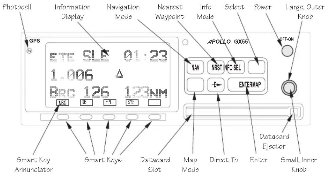
text_image
Photocell GPS Information Display Navigation Mode Nearest Waypoint Info Mode Select Power Large, Outer Knob APOLLO GX55 OFF-ON ETE SLE 01:23 1.006 BRC 126 123NM MSG DB FPL SYS Smart Key Annunciator Smart Keys Datacard Slot Map Mode Direct To Enter Datacard Ejector Small, Inner KnobApollo GX Front Panel Description
A wealth of easy to use features serve the needs of today's demanding aviation requirements. The large waypoint database has information about airports, VORs, NDBs, intersections, and special use airspaces that makes the Apollo GX an encyclopedia of aviation. It's what you'd expect from II Morrow, the first to provide a database in a general aviation navigation aid. The database can be updated by simply changing the removable data card in the front of the unit. The database can also include 500 custom waypoints created by the user. Thirty flight plans can
flight plans can be saved with up to twenty legs for setting up custom tailored routes. The detailed Navigation information displays are also customizable and can be set to automatically scroll through the desired information. The Nearest/Emergency Search feature, invented by II Morrow (Garmin AT), makes it easy to react to an emergency or change your active flight plan.
GX55
The GX55 is designed to be simple slide-in, pin-compatible replacement for panel-mounted Apollo Loran and Flybuddy GPS receivers. The GX55 connectors and antenna footprint are the same as the Apollo Loran and Flybuddy GPS receivers. The GX55 is TSO-C129 Class A2 authorized for IFR en route and terminal operation.
GX50
The Apollo GX50 GPS receiver possesses all of the performance features of the GX55, plus more. The GX50 is TSO-C129a Class A1/JTSO-C129a Class A1 authorized for IFR non-precision approach operation. The GX50 uses the same tray size, but different connections on the back to allow for approach capabilities.
GX60
The Apollo GX60 combines the physical package of the GX50 GPS receiver with a revolutionary VHF Comm transceiver. All of this without the requirement for external cooling.
GX65
The Apollo GX65 possesses the same features as the GX60, except it is not certified for IFR approaches and has TSO-C129a Class A2/JTSO-C129a Class A2.
Display
The display is a 160 by 80 pixel electroluminescent graphic display. A photocell is located in the top left corner of the front panel display. The photocell automatically controls the light intensity of the display from low brightness at night to high brightness during daylight operation.
External Annunciators
When external indicators are installed, the Apollo GX will also provide an external indication when Parallel Track (PTK) is activated or a Message (MSG) is received. The GX50/60 also have external annunciator controls for OBS/Hold and Approach Active. “Hold” refers to suspending waypoint sequencing.
Controls The Apollo GX uses a variety of controls to manage the features. The controls include a power knob, dual-concentric knobs (called LARGE and SMALL), hard keys, and “smart” keys.
Power Knob
The knob on the top right side of the Apollo GX controls power on/off. Rotate the knob clockwise (CW) past the detent to turn the power on. Rotate the knob fully counterclockwise to turn the power off. Full rotation and the push-pull capabilities are only used in the GX60/65.
Power/Volume/Squelch Knob(GX60/65)
The knob on the right side of the GX60/65 controls power on/off, volume, and squelch test. Rotate the knob clockwise (CW) past the detent to turn the power on. Continue rotating the knob to the right to increase speaker and headphone amplifier volume level. Rotate the knob to the left to reduce the volume level. Pull the knob out to disable automatic squelch.
SMALL and LARGE Knobs
The dual concentric knobs on the right side of the front panel are used to select pages, edit characters and values, or other options. The LARGE knob moves the cursor and the SMALL knob changes characters. Either may change pages depending on the function.
Keys There are two types of keys that allow you access to the functions in your Apollo GX: permanent “hard” keys and displayed “smart” keys. Seven back lighted permanent keys are used to reach the functions or perform other operations of the Apollo GX. The “smart” key labels are shown on the bottom of the display. There are two categories of “smart” keys: those available for the Map function and those available at all other times. Press the key below the label to use the displayed function. Press a function key once to go to the last page viewed or twice to go to its “home” page.
Hard Keys The “Hard” keys are the easy-touch, black, rounded keys with white lettering on the right side of the display. These keys include, NAV, NRST, INFO, SEL, MAP, Direct-To, and ENTER.

flowchart
graph LR
    A["NAV"] --> B["NRST INFO"]
    B --> C["SEL"]
    D["MAP"] --> E["D→"]
    E --> F["ENTER"]
NAV
NAV (Navigation)
Press the NAV key to reach the navigation functions. Press twice to go to the “top” page.
NRST
NRST (Nearest Waypoint)
The Nearest Waypoint (Emergency) mode displays the closest waypoints to your position.
INFO
INFO (Information)
The Info function accesses supplementary information about a waypoint. Press INFO a second time to return to the previous display.
SEL
SEL (Select)
The SELECT key activates editing or the selection of options. Editing is active on the items that flash on the display. Press SEL a second time to deactivate selection.
MAP (Graphic Moving Map)
MAP
The Map key starts the Moving Map function. The entire display is used as a graphic map display.
DIRECT-TO
D
The DIRECT-TO key is used to define a direct course from your present position to a waypoint. Press once to select a waypoint. Press twice to enter an OBS desired track To or From the current active waypoint.
ENTER
ENTER
The ENTER key enters and saves the information flashing on the display. If the ENTER key is not pressed after editing, any changes made are not saved. In the GX60/65, the ENTER key flip/flops the Active and Standby frequencies.
"Smart" Keys
The Apollo GX uses “smart” keys to provide custom controls for specialized functions. Five small unlabeled keys are located below the display. The labels appear on the display and can change to give extra controls for the active function, such as in the MAP function. You can always press the NAV key to go back to the Navigation function and view the normal “smart” keys.
MSG (Message)
MSG
Press the MSG key to reach the Message functions.
The MSG annunciator will flash when a new message is provided. Press the MSG key a second time to return to the previous display after all new messages have been viewed. The MSG key will remain highlighted when a message remains.
DB (Database)
DB
The Database key provides access to the waypoint database.
FPL (Flight Plan)
FPL
The Flight Plan key takes you to the flight planning function where you can create, edit, and control your flight plans.
SYS (System Mode)
SYS
Press the SYS key to reach the System mode functions.
System mode is used to make system level adjustments and modify Nav function displays.
SKIP (Start-Up Option)
SKIP
Press the SKIP key during the start-up procedure to bypass the start-up tests. This is for emergencies as the IFR tests must be completed to allow IFR flight.
Map Function Smart Keys
The Moving Map function uses several “smart” keys to allow you to declutter the map, find waypoint information, and setup your map information.
Map Waypoint Keys
APT, VOR, INT, NDB, & USR
APT
NDB
VOR
USR
INT
The map waypoint “smart” keys are present when the Moving Map pages are displayed. Press the “smart”
key to control the display of the waypoint type. There are three selections possible: waypoint identifier and location symbol, location symbol only, and off.
Pressing the “smart” key subsequent times will control which selection is made. Map waypoint choices are: Airport (APT), VOR, NDB, Intersection (INT), and User (USR).
APT
A solid, reversed waypoint type annunciator above the “smart” key means the waypoint identifier and location symbol will both be displayed.
APT
A bold outline of the waypoint type annunciator will show only a symbol on the waypoint location.
NDB
A thin outline around the waypoint type means that it is turned off and no information for that waypoint type will be displayed on the map.
Waypoint LIST Key
2
Each press of this key scrolls through the available “smart” keys.
SCAN
Waypoint SCAN Key
When the SCAN key is active (highlighted) in the Moving Map display, turning the LARGE knob will move between the nearest airports. You can then press INFO to view information about that airport. In an emergency press DIRECT-TO and ENTER to fly direct to the highlighted airport. Press the SCAN key again to return the LARGE knob to normal operation.
Map Setup Keys
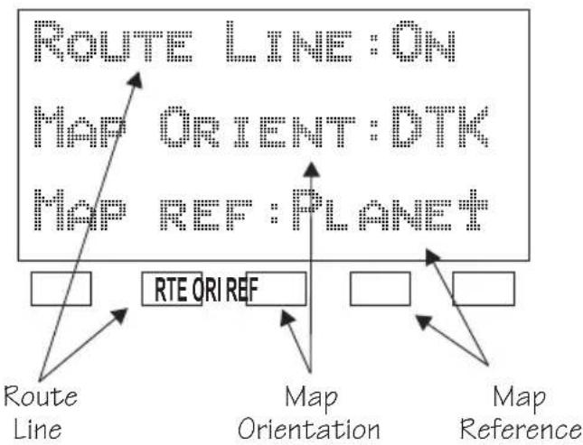
The Map Setup page displays three “smart” keys that provide a short cut for customizing your moving map.
flowchart
graph TD
    A["Route Line"] --> B["RTE ORI REF"]
    C["Map Orientation"] --> D["Map REF: PLANET"]
    E["Map Reference"] --> F["Route Line ON"]
    G["Map Orientation ON"] --> H["Map REF: PLANET"]
    I["Map Reference ON"] --> J["Route Line ON"]
RTE
The Route Line “smart” key toggles between On and Off. See page 4-4 for more details.
ORI
The Map Orientation “smart” key toggles between Desired Track (DTK), Track, and North. See page 4-5 for more details.
REF
The Map Reference “smart” key toggles between Plane and Destination (Dest) as the moving map center point. See page 4-6 for more details.
Communications Radio Mode Smart Keys (GX60/65)
The Recall (RCL), Monitor (MON), Memorize (MEM), and FLIP/FLOP (<->) keys are available in the GX60/65 after the COM soft key has been pressed.
COM (GX60/65)
COM
Press the COM key to operate the Communications radio functions.
Flip/Flop (GX60/65)
←→
Press the FLIP/FLOP key to switch between the active (left-most) and standby (right-most) frequency while in the Com function. You may use an optional external FLIP/FLOP key for the same operation as the front panel control. Switching between frequencies is disabled while you are transmitting or editing in any function.
RCL (Recall) (GX60/65)
RCL
Press the RCL key to recall frequencies stored in the database.
MON (Monitor) (GX60/65)
MON
Press the MON key to listen to the Standby frequency. When the Active frequency receives a signal, the GX60 will automatically switch to the Active frequency.
MEM (Memorize) (GX60/65)
MEM
Press the MEM key to store the current Standby frequency.
XIT (Exit) (GX60/65)
XIT
The XIT key will appear on the far left of the display, in the MSG key position, if the COM key has been pressed to allow use of the radio during startup testing. Press the XIT key to return to the start-up sequence, or wait for test completion. The XIT key will disappear when testing is complete.
Apollo GX Features
Navigation Features
30 Reversible Flight Plans of up to 20 Legs with Automatic Sequencing
500 User-Defined Waypoints
Nav Displays
Lat/Lon
Bearing and Distance
Ground Speed and Track Angle
Desired Track and Distance
Internal CDI Display
160 pixel wide by 80 pixel high electroluminescent display with moving map
Automatic Display Intensity Control
User-Selectable Nav Displays
User-Definable Distance and Speed Settings:
nm and km (distance)
knots
Clock and Countdown Timer
Auto/Manual Magnetic Variation Settings
Direct-To Nav Function
Parallel Track
Nearest Waypoint Search
Internal Database of Airports, VORs, NDBs, Intersections, Frequencies, Airport Info, and controlled and special use airspace
GPS Receiver Performance Specifications
8-Channel Parallel GPS Receiver
Frequency 1575.42 MHz L1, C/A code
Sensitivity (acquisition) -135 dBm
Sensitivity (drop lock) -142 dBm
Dynamic range > 20 dB
Lat/Lon position accuracy
15 meters RMS accuracy
25 meters, SEP, without SA
100 meters 2 DRMS with SA
Velocity 999 knots maximum
Acceleration 4G maximum
TTFF (time to first fix)
25 sec. typ. with current almanac, position, time, and ephemeris
55 seconds typical with current almanac, position, & time
Reacquisition 2.5 seconds typical
Position update interval 1 second typical
Datum WGS-84
Electrical
Input voltage
10 VDC to 40 VDC, reverse polarity protected
Input current (GPS navigation input)
500 mA typical, 750 mA max at 13.75 VDC
250 mA typical, 375 mA max at 27.5 VDC
Input current (comm input - GX60/65 only)
270 mA typical, 2A max at 13.75 VDC, receive
130 mA typical, 900 mA max at 27.5 VDC, receive
2.1A typical, 3.2A max at 13.75, transmit
1.0A typical, 1.4A max at 27.5 VDC, transmit
Input power (GPS navigation input)
7 watts typical
Input power (comm input - GX60/65 only)
3.7 watts typical, receive
28 watts typical, transmit
GX50 and GX60/65 Avionics Outputs
CDI L/R deviation
±150 mv full scale
TO/OFF/FROM flag
±250 mv, TO/FROM indication
Nav valid flag
+300 mv for valid indication
Nav superflag 400 ma source
VDI up/down ±150 mv
VDI valid flag +300 mv
VDI superflag 400 ma source
Annunciators
MSG (message)
PTK (parallel track)
OBS/HLD (waypoint sequencing hold) GX50/60 only
APPRCH (approach enabled) GX50/60 only
ACTIVE (approach active) GX50/60 only
GX55 Avionics Outputs
CDI L/R deviation
±150 mv full scale
TO/OFF/FROM flag
±250 mv, TO/FROM indication
Nav valid flag
+300 mv for valid indication
Annunciators
MSG (message)
PTK (parallel track)
Avionics Inputs
Serial
Frequency flip/flop (GX60/65 only)
Waypoint Sequence (GX50/60 only)
Serial Interface
2 RS-232 for GX50/60/65
1 RS-232 for GX55
Physical Specifications
Height: 2.0 inches (5.08 cm)
Width: 6.25 inches (15.88 cm)
Depth: 11.125 inches (28.26 cm) behind panel, including mounting frame and connectors
Weight (with mounting frame): GX50 and GX55 - 2.6 pounds (1.179 kg) GX60/65 - 3.1 pounds (1.409 kg)
Environmental Specifications
Operating temperature -20°C to +55°C
Storage temperature -55°C to +85°C
Temperature variation 2°C per minute
Humidity cycle) 95% at 50°C for 6 hrs (2 day
Maximum altitude 55,000 feet
Cooling Not required
VHF Comm Features (GX60/65)
760 channels
Frequency range of 118.000 to 136.975 MHz
Active and standby frequency display
Transmit status indicator
Stuck mic time-out
Frequency monitor function - listen to Standby frequency while monitoring Active frequency for any activity
Weather channels - National Weather Service channels (not available in all databases)
Built-in intercom function
Frequency memory and recall functions from navigation data base ten last used ten user stored
Two microphone inputs
12 watt audio amplifier
VHF Comm Receiver Performance Specifications (GX60/65)
Class D
Frequency range - 118.000 to 136.975 MHz, 760 channels
Sensitivity
1 microvolt (2 microvolt hard) for 6 dB S+N/N
30% modulation at 1000 Hz
Selectivity
<6 dB variation at ±22 kHz
Speaker audio output level
12 watts into 4'ohms, 8 watts into 8 ohms
Headphone audio output level
280 mW into 100 ohms, 120 mW into 500 ohms
Distortion - <5% at rated output at 1000 Hz
AGC characteristics
<3dB variation in audio output from 5 to 100 mV input,
15% to 90% modulation
Squelch control - Automatic with manual override
VHF Comm Transceiver Performance Specifications (GX60/65)
Class 4
Output Power
8 watts minimum carrier at > 12 VDC
6 watts minimum at 10 VDC (transmit is locked out below
9 VDC input)
Modulation capability
85% with 100 mv to 1000 mv rms microphone input at
1000 Hz
Duty cycle 100%
Stuck mic time out
35 second time-out, reverts to receive
TSO/JTSO Authorizations
GX50
TSO-C129a Class A1/JTSO-C129a Class A1
GX55
TSO-C129 Class A2
GX60
TSO-C129a Class A1/JTSO-C129a Class A1
TSO-C128/JTSO-2C128
TSO-C37d/JTSO-2C37e Class 4
TSO-C38d/JTSO-C38e Class D
GX65
TSO-C129a Class A2/JTSO-C129a Class A2
TSO-C128/JTSO-2C128
TSO-C37d/JTSO-2C37e Class 4
TSO-C38d/JTSO-C38e Class D
Features and specifications subject to change without notice.
Getting Started
This section explains how to get started using your Apollo GX. Information in this section explains how to:
- Select a waypoint
- Store waypoints
• Find a Nearest Waypoint
• Fly Direct-To a waypoint
• Create a flight plan
• Activate a flight plan
• Use the Moving Map
It is necessary to enter a seed position and the current time the first time you turn the unit on. This should have been done when your unit was installed. So, you won't have to set it again unless the unit has been moved several hundred miles with the power off.
Power On Turn the Power knob clockwise to switch the unit on.
The startup screen, testing, position, and database information shows on the display for several seconds and then will go into the Navigation function.
Select a Waypoint
You can search for a waypoint character by character, sort through the database by selecting the first few characters of the identifier to simplify the search, or look at every waypoint in order. You can search for waypoints by identifier or the city/facility name.
Finding a waypoint by name
- Press the DB smart key. Turn the LARGE knob to display the Access Database page. Press ENTER.

text_image
ACCESS DATABASE PRESS ENTERGetting Started

- The Waypoint Type will flash. Turn the SMALL knob to choose the Waypoint Type (Airport, VOR, NDB, INT, or USER).
AIRPORT HIO PORTLAND CITY OR USA
- Turn the LARGE knob to move the cursor (flashing character) to either the identifier or the city/facility name. Turn the SMALL knob to change the flashing character and show waypoints starting with that character.
AIRPORT HIO PORTLAND CITY OR USA
- Press INFO to look at information about that waypoint or press DIRECT-TO and then ENTER to fly directly to it.
DB

Sorting waypoints by selected characters
- Press the DB smart key. Turn the LARGE knob to display the Access Database page. Press ENTER.
ENTER

- The Waypoint Type will flash. Turn the SMALL knob to choose the Waypoint Type (Airport, VOR, NDB, INT, or USER). Turn the LARGE knob to move the cursor (flashing character) to the identifier or city/facility name. Turn the SMALL knob to change the flashing character and show waypoints starting with that character. In this example, turn the SMALL knob to show a "K."
AIRPORT SVD KADOKA CITY SD USA

- In this case we'll keep the "A" as the second character. Turn the LARGE knob to the third character and then turn the SMALL knob to select an "L."
AIRPORT 09C KALAMAZOO CITY DUP MI USA
SEL
- Now, press the SEL key. Note that the entire name "KALAMAZOO" flashes.
AIRPORT 09C KALAMAZOO CITY DUP MI USA

- Turning the SMALL knob will allow you to choose from all of the waypoints that start with "KAL." Turn the SMALL knob both cw and ccw to check the waypoints.
AIRPORT FCA KALISPELL CITY DUP MT USA

Looking at all waypoints in a database
- Press the DB smart key. Turn the LARGE knob to display the Access Database page. Press ENTER.

- The Waypoint Type will flash. Turn the SMALL knob to choose the Waypoint Type (Airport, VOR, NDB, INT, or USER). Turn the LARGE knob to move the cursor (flashing character) to the Identifier of city/facility name.

- Press SEL. The entire name will flash. Turn the SMALL knob to view all of the waypoints in the selected database starting with the displayed first character of the name.
Duplicate Identifier, City, or Facility Names
While performing Waypoint Identifier selection, you may see the word “dup” on the bottom line. This means that there is more than one waypoint for the displayed city or facility name. The same technique described above can be used to search for duplicate city and facility names.

- While viewing the waypoint database page, turn the LARGE knob to the identifier or facility name field.

-
Press SEL to activate the whole field. Turn the SMALL knob to view the duplicates.
-
If the information is still duplicated, press INFO and turn the SMALL knob to view information about the waypoint.
Waypoint Information
The GX-series contains a wealth of information in its database. Pressing the INFO key will access the information about the destination (TO), or displayed, waypoint.

- Press INFO to view information about the TO waypoint.

text_image
HIO AIRPORT PORTLAND CITY OR USA
- Turn the SMALL knob to view the available information about the TO waypoint. See page 3 for more details about waypoint information.
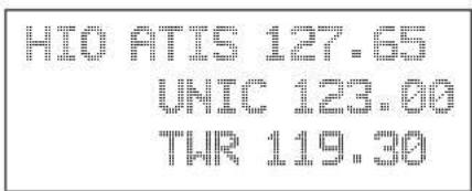
text_image
HIO ATIS 127.65 UNIC 123.00 THR 119.30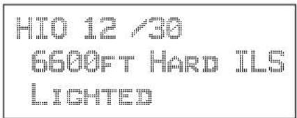
text_image
HIO 12 /30 6600FT HARD ILS LIGHTED
- Press INFO again to return to the previous display.
Storing a Waypoint
Your Apollo GX can store up to 500 user-defined waypoints in the USER database. The waypoint can be created by providing a Lat/Lon position or by a Radial and Distance from a reference waypoint. Then, you can give your waypoint a name and even include a runway length. You can use up to six characters with upper case letters, numbers, or a space for the name. You can also enter a runway length from 0 to 9999 ft. You are not allowed to use a USER waypoint as the Radial and Distance reference waypoint. This example will create a Lat/Lon-based USER waypoint. For more details on waypoints, see the Waypoint Database section on page 5-1.

- Press DB. Turn the LARGE knob to the Create User Wpt page. Then, press ENTER.

text_image
CREATE USER HPT BY LAT/LON PRESS ENTER
- The pound sign (#) will flash in front of the next number available for your USER waypoint. You can press ENTER now to save your present position with the displayed name or you can use the LARGE and SMALL knobs to change the information.
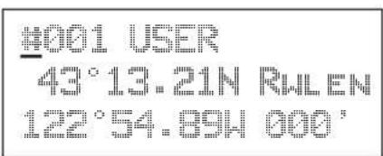
text_image
#001 USER 43°13.21N RWLEN 122°54.89W 000'Finding a Nearest Waypoint
When you press the NRST key, your Apollo GX will search for the nearest 20 waypoints within 600 nm for each waypoint type. You can also be selective about the runway length, lighting, and surface type. See Setting Runway Limits on page 3-12.
NRST
- Press the NRST key. The Nearest Waypoint function is displayed with the distance and bearing from your present position to the indicated waypoint.
NEAR 1 TO PPOS SLE AIRPORT BRC 352°↑ 5.4NM
- Turn the LARGE knob to view the different waypoint types.
NEAR 1 TO PPOS UBG VOR BRC 344°↑ 26.6NM

- Turn the SMALL knob to view the 20 nearest waypoints.
NEAR 2 TO PPOS CVO VOR BRC 189°↓ 27.5NM

- To quickly navigate to a Nearest Waypoint, press DIRECT-TO and then ENTER.
ENTER
Note
The last viewed Nearest Waypoint will be the waypoint shown the next time you want to insert a waypoint. For instance, if you press NRST and look at PDX, the next time you want to insert a waypoint into a flight plan, PDX will show first.

Flying Direct-To a Waypoint
Pressing DIRECT-TO allows you to quickly make changes to your TO waypoint. When you press DIRECT-TO, the default waypoint shown will be the current TO waypoint in the Nav or Flight Plan functions or the waypoint displayed in the Database or Info functions. See page 3-31 for more details.

- Press the DIRECT-TO key. The display will go directly into the Waypoint Database and the waypoint type will flash.
VOR CNO SALEM CITY OR USA

- Use the LARGE and SMALL knobs with one of the Waypoint Selection techniques described on page 2-1 to choose a waypoint.
ENTER
- After selecting the desired waypoint, press ENTER. Your Apollo GX will now switch to the Navigation function and show information based on a direct route from your present position to the Direct-To destination waypoint.
ETE AHIO 00:12 △ 0.002 BRC 346 35.2NMT
Note
See Direct-To Entry Options on page 7-8 in the System Functions chapter for details. When the option is set to “May Clear,” your active flight plan is deleted when you use Direct-To for flying to a new destination. If your new Direct-To waypoint is in the active flight plan, the flight plan is not deleted. When the option is set to “Never Clears,” the Direct-To waypoint is inserted into your active flight plan before the current TO waypoint. “May Clear” is the default setting.

Create a Flight Plan
You can create up to 30 flight plans with up to 20 legs each. A flight plan name can have up to eight characters using upper case letters, numbers, or a space.


- Press FPL. Turn the LARGE knob to reach the Create a New Flight Plan page. Then, press SEL.
PRESS SEL TO CREATE A NEW FLIGHT PLAN

- The Plan Name page will appear and the first space will flash. The underlined spaces will disappear after you name the flight plan. Use the LARGE knob to move the cursor. Use the SMALL knob to select characters.
ENTER A NEW PLAN NAME


- After naming your flight plan, press ENTER. You will now have the choice of inserting waypoints into the flight plan or performing other options. Turn the SMALL knob to start inserting waypoints. This example will cover inserting waypoint.

Note
You may also press SEL for options, such as Rename Plan, Copy Plan, Estimated Ground Speed, Estimated Fuel Flow, or Delete Plan. See page 6-14 for more details on the flight plan options.
TURN SMALL KNOB TO INS HPTS OR SEL FOR OPTIONS
SEL
- The first flight plan leg page will be displayed. Press SEL to start inserting waypoints.

text_image
TO 1 PRESS SEL TO EDIT LEG
- The Ins? prompt will flash. Press ENTER. This will take you to the waypoint database. Use the LARGE and SMALL knobs as described in the Select Waypoint section starting on page 2-1. Press ENTER after selecting a waypoint.

text_image
INS? TO 1 "NMSEL
- The identifier will be entered and the TO waypoint position for the first flight plan leg will have a flashing "Ins?" prompt. Continue entering waypoints into your flight plan. Press SEL to quit inserting waypoints.

text_image
SLE TO INS? 1. 0. NMActivating a Flight Plan
Select a flight plan from your stored plans. Activating a flight plan copies it into the Active page.

- Press FPL. Turn the LARGE knob to the desired flight plan.
SEL
- Press SEL. The bottom line of the flight plan display will flash. Turn the SMALL knob to choose "Activate?".
Using the Moving Map
The Moving Map gives you a graphic presentation of your flight progress. You can select the type of waypoint displayed, a route line, ATC ring, airspace setup, type of airspace displayed, and map orientation. See the Moving Map section on page 4-1 for more details.

Viewing the Moving Map
- Press MAP. Turn the LARGE knob to view the map and nav information, full screen map, and map setup displays.

- While viewing the map, turn the SMALL knob to change the map scale.

text_image
Special Use Airspace Distance to the TO Waypoint TO Waypoint Identifier Ground Speed Route Line Your Present Position Cross Track Error Distance & Direction TO APDX 44.2 120 NM KT 005 1000 BRG TRK (0.6) > 30 Bearing to the TO Waypoint Current Track Map ScaleSetting Up the Moving Map
- Press MAP. Turn the LARGE knob to the Map Setup page. Note the diamond ( ) in the lower right corner of the display. This diamond means there are more pages for a function. Turn the SMALL knob to view the other Map Setup pages.

ROUTE LINE:OFF MAP ORIENT:TRACK MAP REF:PLANE

flowchart
graph TD
    A["SEL"] --> B(( )) --> C["ENTER"]
    B --> D(( )) --> E["---"]
- Change the displayed values by pressing SEL, turning the LARGE knob so the desired item flashes, turning the SMALL knob to change the item, and then press ENTER.

flowchart
graph TD
    A["Navigation (NAV)"] --> B["Press NAV"]
    B --> C["E T E & B R G"]
    B --> D["RAIM Prediction"]
    B --> E["Altitude Assist"]
    B --> F["Parallel Track (PTK)"]
    B --> G["GPS Position"]
    B --> H["Countdown Timer"]
    B --> I["Arc Assist"]
    B --> J["To/Next Wpt (Distance)"]
    B --> K["To/Next Wpt (ETE)"]
    B --> L["To/Next Wpt (ETA)"]
    B --> M["From/To/Next Waypoint"]
    B --> N["Tuned Station * when configured"]

    O["Nearest Waypoint (NRST)"] --> P["Turn Large Knob"]
    P --> Q["Airport (ARPT)"]
    P --> R["VOR"]
    P --> S["NDB"]
    P --> T["INT"]
    P --> U["LocDME"]
    P --> V["User WPT"]
    P --> W["Search Around WPT"]
    P --> X["Runway Limits"]
    P --> Y["SUA"]

    Z["Waypoint Information (INFO)"] --> AA["Turn Large Knob"]
    AA --> AB["Ident, Type, & Name"]
    AA --> AC["Radial & Dist"]
    AA --> AD["Bearing & Dist"]
    AA --> AE["Map"]
    AA --> AF["Frequencies"]
    AA --> AG["Approaches"]
    AA --> AH["Lat/Lon"]
    AA --> AI["Sunrise/Sunset"]
    AA --> AJ["WPT Comment"]

    AK["Moving Map (MAP)"] --> AL["Turn LARGE Knob"]
    AL --> AM["Map plus Nav & Comm Info"]
    AL --> AN["Map plus Nav Info"]
    AL --> AO["Map Only"]
    AL --> AP["Search & Rescue Map"]
    AL --> AQ["Map Setup"]

    AR["Select (SEL)"] --> AS["Press SEL to edit information or to select options."]
    AT["Enter (ENTER)"] --> AU["Press ENTER to enter and save information. In the Comm function, ENTER saves the Standby frequency."]
    AV["Direct-To (-D)"] --> AW["Press Direct-To to define a direct course from your present position to a selected waypoint."]

    AX["Press the indicated button and then turn the LARGE knob to view the pages shown. Turn the SMALL knob for further info when available (diamond shown)."] --> AY["press the indicated button and then turn the large knob to view the pages shown. Turn the small knob for further info when available (diamond shown)."]

    AZ["*when enabled"] --> BA["Airspace Types (B, C, MOA, Training, Unknown, Alert, Caution, Danger, Restricted, Prohibited, & Warning)"]
    AZ --> CA["Search & Rescue Setup*"]
    AZ --> DA["SAR Position*"]

flowchart
graph TD
    A["Messages (MSG)"] --> B["Press MSG"]
    B --> C["New"]
    B --> D["Old"]
    C --> E["New Msg 1"]
    C --> F["New Msg n"]
    D --> G["Old Msg 1"]
    D --> H["Old Msg n"]
    I["Database (DB)"] --> J["Press DB"]
    J --> K["Create WPT by Lat/Lon"]
    J --> L["Create WPT by Radial/Dis"]
    J --> M["Update User WPT"]
    J --> N["Create WPT by Grid"]
    J --> O["Delete User WPT"]
    J --> P["Modify User WPT"]
    J --> Q["Delete WPT Comment"]
    J --> R["Access Database"]
    S["Flight Plan (FPL)"] --> T["Press FPL"]
    T --> U["Active FPL"]
    T --> V["FPL #1"]
    T --> W["FPL #30"]
    T --> X["Create New FPL"]
    Y["Comm Radio (COM)"] --> Z["Press COM"]
    Z --> AA["Turn LARGE Knob to change MHz"]
    Z --> AB["Turn SMALL Knob to change kHz"]
    Z --> AC["Press <-> to toggle Active & Standby"]
    Z --> AD["Press MON to monitor Standby"]
    Z --> AE["Press MEM to memorize Standby"]
    Z --> AF["Press RCL to recall stored frequencies"]
    Z --> AG["Turn the LARGE Knob to view frequency types"]
    Z --> AH["Turn the SMALL Knob to view frequencies for selected type"]
flowchart
graph TD
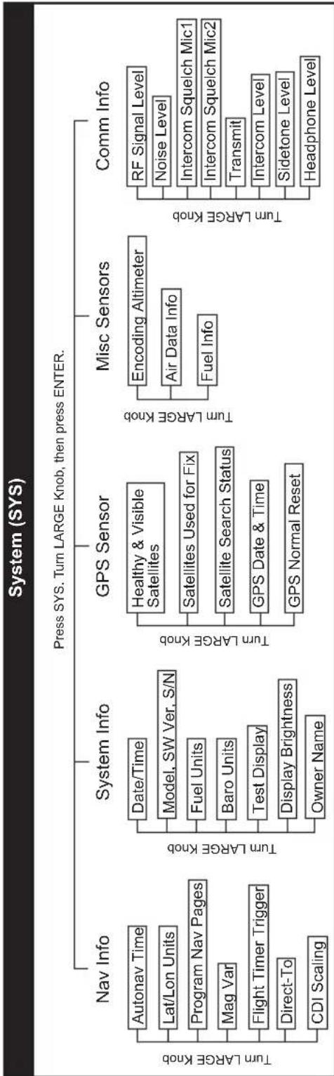
A["System (SYS)"] --> B["Press SYS. Turn LARGE Knob, then press ENTER."]
B --> C["Nav Info"]
B --> D["System Info"]
B --> E["GPS Sensor"]
B --> F["Misc Sensors"]
B --> G["Comm Info"]
C --> H["Autonav Time"]
C --> I["Lat/Lon Units"]
C --> J["Program Nav Pages"]
C --> K["Mag Var"]
C --> L["Flight Timer Trigger"]
C --> M["Direct-To"]
C --> N["CDI Scaling"]
D --> O["Date/Time"]
D --> P["Model, SW Ver, S/N"]
D --> Q["Fuel Units"]
D --> R["Baro Units"]
D --> S["Test Display"]
D --> T["Display Brightness"]
D --> U["Owner Name"]
E --> V["Healthy & Visible Satellites"]
E --> W["Satellites Used for Fix"]
E --> X["Satellite Search Status"]
E --> Y["GPS Date & Time"]
E --> Z["GPS Normal Reset"]
F --> AA["Encoding Altimeter"]
F --> AB["Air Data Info"]
F --> AC["Fuel Info"]
G --> AD["RF Signal Level"]
G --> AE["Noise Level"]
G --> AF["Intercom Squelch Mic1"]
G --> AG["Intercom Squelch Mic2"]
G --> AH["Transmit"]
G --> AI["Intercom Level"]
G --> AJ["Sidetone Level"]
G --> AK["Headphone Level"]
Navigation Basics
This section explores the navigation function and describes the powerful features it contains.
About the Navigation Function
The navigation function is always active. When you use other functions, the navigation function continues to run “in the background” calculating your present position, navigating your programmed route (if active), and alerting you to events or conditions important to navigation. When you finish using other functions and return to the navigation function, the last navigation display used is shown.
About the Navigation Function Displays
While you navigate, the Apollo GX gives you information in the Navigation function displays. The navigation information displays and sequencing rate are user-programmable. See the Nav info section of the System Functions chapter (see page 7-1) for your options. The LARGE knob will select the higher level Nav functions: Nav pages, Parallel Track Offset, GPS Position, Countdown Timer, and the FROM/TO/NEXT Waypoints. The SMALL knob will look at the pages available for each function; a diamond (‡) will be shown on the lower, right side of the display if more pages are available.
Nav Home Page
The Nav Home Page is a default page that is the first page available in the Navigation function. The Nav Home Page is not customizable. The information in the Home Page shows the Destination Waypoint identifier, Estimated Time En Route, CDI, Bearing, and Range (distance) to the destination waypoint.
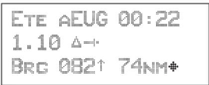
text_image
ETE AEUG 00:22 1.10 △→ BRC 032↑ 74NM♦
Turn the SMALL knob to view the other available Navigation displays.
text_image
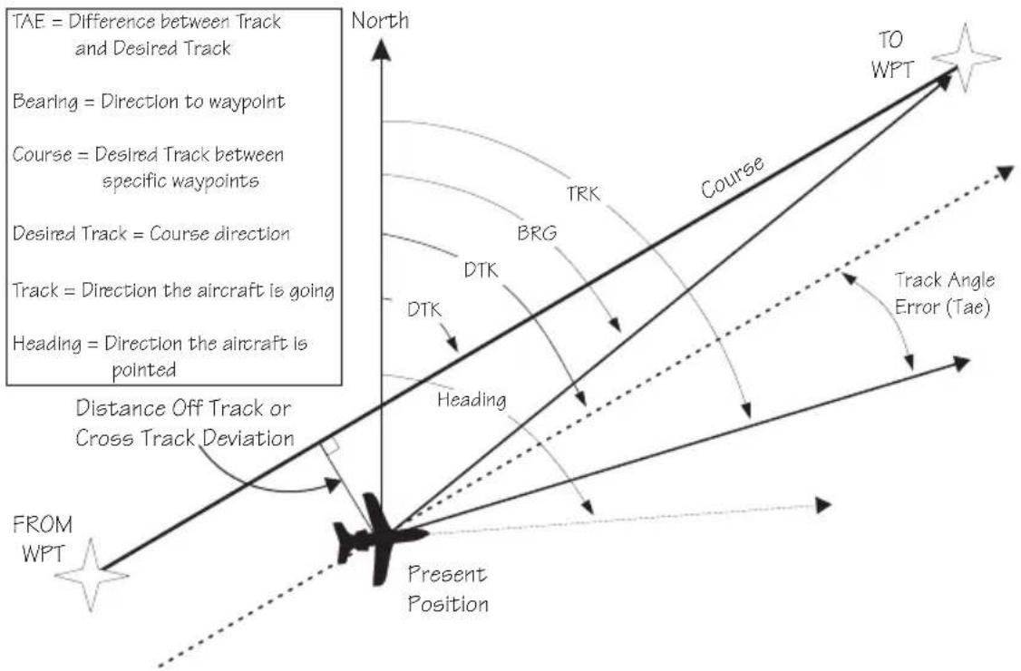
TAE = Difference between Track and Desired Track Bearing = Direction to waypoint Course = Desired Track between specific waypoints Desired Track = Course direction Track = Direction the aircraft is going Heading = Direction the aircraft is pointed Distance Off Track or Cross Track Deviation FROM WPT North TRK BRG DTK DTK Heading Present Position TO WPT Track Angle Error (Tae)Navigation Terms and Abbreviations
Autonav
The Autonav feature lets you select certain Nav display choices and have them rotate in sequence displaying each one from one to nine seconds. The selection of displays and sequencing time is performed in the Nav Info part of the System Functions (see page 7-1).
ENTER
- Start Autonav by pressing ENTER while displaying the Nav Home Page, or one of its sub-pages.
ETE AEUG 00:22 1.10 A... BRC 082↑ 74NM+
- Stop Autonav rotation by pressing any key or turning either knob. Leaving the Nav function will also disable Autonav.
Relative Bearing Indicator
The Relative Bearing Indicator is an arrow next to the Bearing value that indicates an approximate bearing to a waypoint or airspace relative to the aircraft's current track when your current ground speed is more than 5 knots. The following illustration describes the bearing range for each arrow.
| 7 | ÷ | ÷ | |||||
| 23°to67° | 68°to112° | 113°to157° | 158°to202° | 203°to247° | 248°to292° | 293°to337° | 338°to22° |
31 000 32 000 33 000 34 000 35 000 36 000 37 000 38 000 39 000 40 000 41 000 42 000 43 000 44 000 45 000 46 000 47 000 48 000 49 000 50 000 51 000 52 000 53 000 54 000 55 000 56 000 57 000 58 000 59 000 60 000 61 000 62 000 63 000 64 000 65 000 66 000 67 000 68 000 69 000 70 000 71 000 72 000 73 000 74 000 75 000 76 000 77 000 78 000 79 000 80 000
PDX HILIPPORT
Brc 010↑ 39.7MM
Nav Pages
The Apollo GX provides a wide variety of navigation information. This information is provided on a number of displays that you can view by turning the LARGE knob. Some displays have a diamond in the lower right corner; turn the SMALL knob to view more related information.
text_image
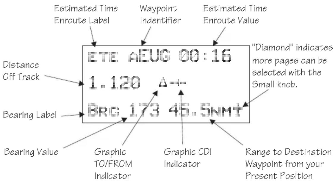
Estimated Time Enroute Label Waypoint Indentifier Estimated Time Enroute Value Distance Off Track Bearing Label BRC 173 45.5NMT "Diamond" indicates more pages can be selected with the Small knob. Bearing Value Graphic TO/FROM Indicator Graphic CDI Indicator Range to Destination Waypoint from your Present PositionEstimated Time En Route (Ete)
ETE is to the current TO (destination) waypoint from your present position based on the current ground speed. The units shown are in hours and minutes, 00:00 to 99:59, and in seconds when less than one hour is displayed. If the ground speed is less than or equal to 5 knots, the GPS receiver does not have a valid position, or there is no TO waypoint, the ETE value will be shown as dashes. If there is no TO waypoint, the TO identifier location will be replaced by dashes.
Bearing (Brg)
Bearing is the angle from your present position to the TO waypoint. Bearing is shown from 0 to 359 degrees in one degree increments. Bearing is computed using the magnetic variation at the Present Position. The Bearing value will be dashed if the FROM or TO waypoints are blank or the GPS receiver does not have a valid position.
text_image
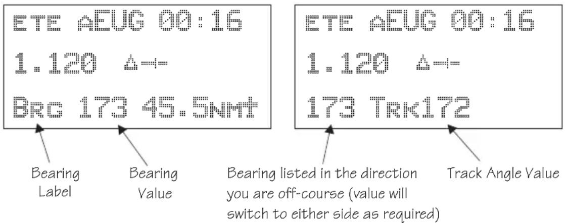
ETE AEUG 00:16 1.120 44- BRC 173 45.5NMT Bearing Label Bearing Value Bearing listed in the direction you are off-course (value will switch to either side as required) Track Angle Value ETE AEUG 00:16 1.120 44- 173 TRK172Range (Rge)
The distance from your present position to the TO waypoint. Units can be set as either nautical miles or kilometers in the Nav Info section of the System functions (see page 7-6). Nautical mile units are 0.00 to 9.00 nm in 0.01 nm increments, 10.0 to 99.9 nm in 0.1 nm increments, and 100 to 9999 nm in 1 nm increments. Kilometer units are 0.00 to 99.99 km in 0.01 km increments, 100.0 to 999.9 km in 0.1 km increments, and 1000 to 9999 km in 1 km increments. The Range value will be dashed if the FROM or TO waypoints are blank or the GPS receiver does not have a valid position.
Course Deviation Indicator (CDI) and Distance Off Track
The triangle symbol ( ) referenced to a bar graph shows your position relative to being on-course. When the bar graph is to the right of the triangle, you must fly right to return on-course. In the example below, the bar graph indicates you are off-course to the right. Fly the aircraft in the direction of the bar graph (left) to return on-course.
| ETE ASLE 00:37 |
| 4.005 |
| BRC 173" 42.4NM |
| CDI Sensitivity = 0.3 nm | CDI Sensitivity = 1.0 nm | CDI Sensitivity = 5.0 nm |
| each * = 0.01 nm | each * = 0.05 nm | each * = 0.24 nm |
| each ** = 0.04 nm | each *** = 0.14 nm | each *** = 0.71 nm |
| (full scale) = 0.3 nm | (full scale) = 1.0 nm | (full scale) = 5.0 nm |
A single dot thickness bar indicates that CDI sensitivity is set to 0.3 nm full scale per side. The two dot bar indicates a sensitivity of 1.0 nm full scale per side. The three dot bar indicates a sensitivity of 5.0 nm full scale per side. The manual sensitivity of the CDI may be set to 0.3, 1.0, or 5.0 nm full scale per side.
The number shown on the edge of the display opposite from the triangle symbol shows the distance off track. The numbered values of Cross Track Error are in the direction you are off course. If the numbers are on the left side, fly right to return on course. The displayed value ranges are: 0.000 to 0.999 nm with 0.001 nm resolution, 1.0 to 9.99 nm with 0.01 nm resolution, and 10.0 to 99.9 nm with 0.1 nm resolution.
| ETE ASLE | 00:37 |
| 0.006 | |
| BRC 173 | 42.4NM |
If the GPS sensor is not sending a valid position, or the current TO waypoint is blank, the CDI will display “—Nav Flagged—”.
TO/FROM Indicator
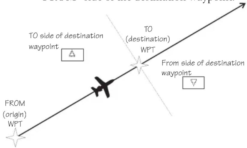
The triangle symbol is also used as a TO-FROM indicator. When the triangle is facing up, you are on the “TO” side of the destination waypoint. When the triangle is facing upside down, you are on the “FROM” side of the destination waypoint.
text_image
FROM (origin) WPT TO side of destination waypoint TO (destination) WPT From side of destination waypointDesired Track (Dtk)
Desired Track is the initial course angle between the FROM and TO waypoints referenced to the magnetic variation at the current FROM waypoint. Desired Track is shown from 0 to 359 degrees in one degree increments and is updated in reference to your present position. The Leg distance shown (42.4 nm) is the current FROM/TO distance. DTK varies with Turn Anticipation (page 3-36) and DME Arcs (page 9-26).
ETE ASLE 00:37 0.005 △ DTK 173 42.4NM
Leg (FROM-TO) Distance
The distance from current FROM waypoint to the current TO waypoint is shown as a value on the right side of the Desired Track page, but does not show any label. In this example, the leg (FROM-TO) distance is 42.4 nm. The nautical mile units are 0.00 to 9.99 nm at 0.01 nm resolution, 10.0 to 99.9 nm at 0.1 nm resolution, and 100 to 9999 nm at one nm resolution. Kilometer units are 0.00 to 99.99 km at 0.01 km
resolution, 100.0 to 999.9 km at 0.1 km resolution, and 1000 to 9999 km at 1 km resolution. See page 7-6 for details on changing units of measurement.
Track (Trk) Angle
Track Angle is the angle of your actual direction of travel. Track is shown as a positive value from 0 to 359 degrees in one degree increments. Track is computed using the magnetic variation at the Present Position. The Track value will be dashed if the FROM or TO waypoints are blank, if the GPS receiver does not have a valid position, or if ground speed is less than 5 knots.
ETE AGLE 00:37
B. 2016
TRK 175 TAE QD2R
Track Angle Error (Tae)
Track Angle Error is the difference between the Desired Track and Track Angle (Dtk - Trk). Track Angle Error is shown from 0 to 359 degrees in one degree increments. Track Angle Error is computed using the magnetic variation at the Present Position. The Track Angle Error value will be dashed if the FROM or TO waypoints are blank, if the GPS receiver does not have a valid position, or if ground speed is less than 5 knots. A letter R or L) will show the direction of the error in relation to track angle.
TAE = Difference between Track and Desired Track
Desired Track = Course direction
Track = Direction the aircraft is going
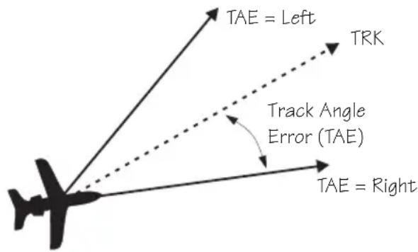
text_image
TAE = Left TRK Track Angle Error (TAE) TAE = RightGround Speed (GS)
Ground Speed is the measure of your progress over the ground, not airspeed. Ground Speed units are from 0 to 999 knots in 1 knot increments. The Ground Speed value will be replaced with dashes if the speed is less than 5 knots, there is no valid GPS position, or the TO waypoint is blank. See page 7-6 for details on changing units of measurement.
ETE ASLE 00:37
Minimum Safe Altitude (MSA)
MSA is calculated by taking the Maximum Elevation Figure (MEF) from the sectional chart grid that corresponds to your current position. In areas below 3,000 feet, 1,000 feet is added. In areas above 3,000 feet, 2,000 feet is added. In the example below, the current aircraft would be considered to be at 7,000 feet. If you are within 5 nm of another grid with a higher MEF, the higher MEF will be used. The MEF on the sectional chart is derived by taking the altitude of the highest obstruction within the grid, rounded up to the next 100 feet, and adding 300 feet. For example, if the highest obstruction is 4,728 feet, the MEF would show as 5,100 feet.

scatter
| Point Type | X Coordinate | Y Coordinate | | ---------------- | ------------ | ------------ | | MEFs | 2^4 | 2^4 | | MEFs | 2^8 | 2^8 | | MEFs | 5^2 | 5^2 | | MEFs | 6^5 | 6^5 | | MEFs | 14^8 | 14^8 | | TO Waypoint | 4^5 | 4^5 | | TO Waypoint | 6^3 | 6^3 | | TO Waypoint | 14^1 | 14^1 | | TO Waypoint | 6^5 | 6^5 | | TO Waypoint | 14^8 | 14^8 | | 5 nm Buffer | 6^3 | 6^3 | | MESA | 14^1 | 14^1 | ETA ASLE 01:23 | | | | MINSAFEA 7200' | | | | ENRTSAFEA 16800' | | |Minimum En Route Safe Altitude (MESA)
Minimum En Route Safe Altitude is the highest MSA for every point between the aircraft present position and the “TO” waypoint with a 5 n m buffer around the course. The value will be replaced with dashes if there is no valid GPS position, the TO waypoint is blank, or the current position is outside of the
database coverage area. In the example shown above, the MESA for the present position of the aircraft would be 16,800 ft. The mountainous terrain would add a 2,000 ft. buffer to the 14,800 ft. Maximum Elevation figure indicated from the sectional chart.
Flight Time
Flight Time shows the elapsed time in hours and minutes (00:00 to 99:59) from departure. If the Flight Timer is not started the value will be replaced with dashes. The Flight Timer Trigger options are set in the System Functions (see page 7-8).
FTOG:07
Time UTC
Time is displayed using the 24 hour clock based on Universal Coordinated Time. Units are hours and minutes (00:00 to 23:59).
13:15 UTC
Estimated Time of Arrival (ETA)
The ETA is the arrival time at the current TO waypoint at the current Ground Speed from the present position. The TO waypoint is displayed. Units are hours and minutes (00:00 to 23:59) based on the UTC 24 hour clock. The values will be replaced with dashes if the speed is less than 5 knots, there is no valid GPS position, or the TO and/or destination waypoints are blank.
ETTA PEUG 09:11
Nearest Waypoint & Airspace Search
An important safety feature of the GX is its ability to locate waypoints and airspaces closest to your position. Should you have to land quickly, you can use this feature to locate a nearby waypoint, assign it as a destination, and quickly navigate to it. You can also insert waypoints into an active flight plan. Besides the nearest waypoints to your present position, as an aid in flight planning, you can also select a reference waypoint from the database and search for waypoints near to it. You can set up the Nearest Waypoint Search function to filter for certain
Navigation Basics
airport types you select, such as: runway length, lighting, and surface type. Press INFO while viewing a Nearest waypoint for more information about that waypoint.
Starting Nearest Waypoint & Airspace Search
NRST

- Press the NRST key. Turn the LARGE knob to display the waypoint type or options: Airport, VOR, NDB, Intersection (INT), User (USER), Choose Reference Waypoint, Runway Limits, and Special Use Airspace.
NEAR 1 TO PPOS SLE AIRPORT BRC 352°↑ 2.4NM

- Turn the SMALL knob to display the nearest 20 waypoints. The waypoints must be within 600 miles of your present position. The Bearing and Distance to the displayed waypoint is shown on the right side of the display. Press DIRECT-TO and then ENTER to set the displayed waypoint as the new destination (TO) waypoint.

ENTER
NEAR 12 TO PPOS CVO AIRPORT BRC 188°↓ 27.6NM
Searching Around a Reference Waypoint
Use this function to search for the 20 nearest waypoints of each type (including airspaces) within 600 miles of a reference waypoint selected from the database. This can be used as an aid to flight planning for waypoints far away from your present position.

ENTER
- While in the Nearest Waypoint function, turn the LARGE knob to view "Choose Waypoint to Search Around" and press ENTER.
CHOOSE NPT TO SEARCH AROUND PRESS ENT

- The waypoint type will flash. Turn the SMALL knob to choose Airport, VOR, NDB, Intersection (INT) or User waypoint type.
VOR PIN PORTLAND FACIL OR USA

- Turn the LARGE knob to the waypoint identifier name. The first character of the identifier will flash. Turn the SMALL knob to change characters. Turn the LARGE knob to select the next character to change.
AIRPORT SALE SALEN CITY OR USA
ENTER
- Press ENTER. The Nearest waypoints (and airspaces) will now be referenced to the selected search waypoint rather than your present position.
NEAR 1 TO SLE SLE AIRPORT BRC 110° 0.5NM
- Turn the SMALL knob to view the nearest 20 waypoints of the selected type to the selected reference waypoint. Turn the LARGE knob to change waypoint types.

Note
The last viewed Nearest Waypoint will be the waypoint shown the next time you want to insert a waypoint. For instance, if you press NRST and look at PDX, the next time you want to insert a waypoint into a flight plan, PDX will show first.
Setting Runway Limits for Nearest Waypoints
Narrow the type of airports that you will accept by choosing the runway length, lighting, and surface type. The Runway Limits selection also controls the airports that are displayed in the Map function.

- While in the Nearest Waypoint Search function, turn the LARGE knob to view the “Runway Limits” display.
RUNWAY LIMITS HARD/SOFT/WATER FT:0 LIT:No
SEL

- Press SEL. The runway length value will flash. Turn the SMALL knob to select the minimum runway length you want considered. Choosing a length of 0 feet means you will accept any runway length. Choosing a runway length, for instance, of 5,000 feet, will not show an available airport with a runway length less than 5,000 feet either for a Nearest Waypoint or as an airport icon on the Map display. Note that a waypoint with a runway of 0 length will not appear on either the nearest list, or on the map, if a length is set for the runway limit that is greater than 0. User Waypoints will show.
RUNWAY LIMITS HARD/SOFT/WATER FT:3500 LIT:NO

- Turn the LARGE knob to move to the next selection. With the "Lit" value flashing, turn the SMALL knob to choose "Yes" or "No" for the runway lighting requirement.
RUNWAY LIMITS HARD/SOFT/WATER FT:3500 LIT:YES

- Turn the LARGE knob to cause the runway surface type to flash. Turn the SMALL knob to choose from the Hard, Soft, or Water surface types. Soft refers to grass, dirt, or gravel runways. Choices include: Hard, Hard/Soft, and Hard/Soft/Water.
RUNNAY LIMITS HARD/SOFT FT:3500 LIT:YES
ENTER
Controlled Special Use Airspace
- Press ENTER to save your choices or press SEL again to disable selection and to ignore any changes you have selected.
When searching around your present position, the first ten airspaces within 100 miles are displayed. While searching for airspaces, the keys and knobs are disabled and the following display will appear.
SEARCHING FOR AIRSPACES =
The information for airspaces includes: name, position in the list (1-10), type, and proximity. Proximity is indicated as either: Soon, Outside, Inside, Above, Below, or Close. Criteria for airspace searches is set in the System functions (see page 4-12). For proximity definitions, see page 8-3.
“MSL” stands for feet above Mean Sea Level. “AGL” stands for feet Above Ground Level.
KANSAS CITY 1 CLASS B 500N BRC 210° ↑ 7.1NM
INFO
- Press the INFO key to view information about the airspace. Values for ceiling and floor may be any number of positive feet less than 100,000. Values may also be Unlimited, Ground, FL (Flight Level, followed by a number such as 050), Unknown, or NOTAM.
KIMNMS CITY
C. 11: : 12:00-13:00
- Turn the SMALL knob to view more information about the airspace.
The Nearest Airspace list is updated periodically as your aircraft moves and the following display may appear.
RE-ORGANIZING
PII PSPAGES
Altitude Assist provides guidance for your vertical navigation needs. Altitude Assist features require the system to include either a Fuel/Air Data Sensor (F/ADS) or an altitude encoder sensor.
The features available in the Altitude Assist function are:
• Set Local Altimeter value
• View Encoder Altitude value
- Set and activate Auto Descent Values (Ending Altitude, Distance from the Destination Waypoint, Descent Rate, and estimated speed)
• Set and activate Hold Altitude and Buffer
In the Nav function, turn the LARGE knob to view the Altitude Assist page. The diamond in the corner notes that turning the SMALL knob will show the Encoder Altitude, Auto Descent, End Altitude, and Hold Altitude, and Buffer values.
ALTITUDE ASSIST LOCAL ALTIMETER SETTING 29.92" +
Setting the Local Altimeter Value
- While viewing the Altitude Assist page, press SEL. The setting value will flash. The default barometric pressure setting is 29.92".
If an Air/Data Sensor is installed and provides corrected baro-altitude, barometric altitude will be displayed instead of the altimeter setting.
ALTITUDE ASSIST LOCAL ALTIMETER SETTING 29.92 +
- Turn the SMALL knob to change the values. Press ENTER when complete.
ALTITUDE ASSIST LOCAL ALTIMETER SETTING 29.92" +
Encoder Altitude
The altitude information received from the altitude sensor is displayed on this page if an altitude encoder or F/ADC is installed. You cannot change these values.
ENCODER ALTITUDE 2006FT
SEL

ENTER
Setting Hold Altitude and Buffer
The Hold Altitude is an altitude where you want to remain. The Buffer is the tolerance or range in altitude that you can move in vertically before a warning message is generated.
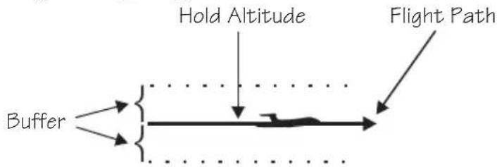
text_image
Buffer Hold Altitude Flight Path
- In the Nav function, turn the LARGE knob to the Hold Alt/Buffer page. Press SEL. The Hold Altitude value will flash.
HOLD ALT 5650FT BUFFER 150 FT ENT TO HOLD ALT

- Turn the SMALL knob to change the value.
- Turn the LARGE knob to the Buffer value. Turn the SMALL knob to change the value.
HOLD ALT 4550FT BUFFER 150 FT ENT TO HOLD ALT
ENTER
- Press ENTER to save the values. Press ENTER again to activate the Hold Altitude.
HOLD ROY 4550FT BUFFER 100FT ENT TO CANCEL
ENTER
- Pressing ENTER again will cancel the Hold Altitude.
Auto Descent
The Auto Descent feature allows you to input a desired End Altitude, an Offset Distance from a desired Auto Descent Waypoint from the Active flight plan, a desired Feet per Minute Descent rate, and an expected Ground speed. It then automatically calculates the distance remaining in your Active flight plan to the desired Auto Descent Waypoint and, based on the calculated glide path angle, your present altitude, and the altitude you are descending to, alerts you with a message when you should begin and end your descent. A Nav item field displays information indicating how much time remains before you should begin Auto Descent, and once Auto Descent begins, whether you are above or below your intended Glide Path. Glide Path data may also be output to an optional Vertical Deviation or HSI Glide Slope Indicator.

text_image
Flight Path Auto Descent Starting Point Auto Descent Slope Auto Descent Waypoint Destination Waypoint Auto Descent Offset Distance End AltitudeEach time you begin to edit the Auto Descent values, the End Altitude is automatically reset to 1,000 feet over the altitude of the desired Auto Descent Waypoint, if the waypoint is an airport. Otherwise, the End Altitude automatically resets to 2,000 feet. In addition, the default Auto Descent Waypoint is automatically updated, as long as Auto Descent is OFF, to the current TO waypoint each time a waypoint sequence occurs.
Navigation Basics
Set up your Auto-Descent by selecting:
• Distance from destination waypoint (0 - 99 nm) or Offset Distance
• Ending altitude (-1,500 - 50,000' in 50' steps)
• Descent rate (100 - 5,000'/min in 10'/min steps)
• Estimated ground speed (50 - 600 kts)

- While viewing either the Auto-Descent or End Alt page in the Altitude Assist function, press SEL. The Offset Distance value will flash. Turn the SMALL knob to change the Descent Offset Distance value.
END 5NM BEFORE PDX AT 1027' 500' /MIN 200KTS
- Turn the LARGE knob to the destination waypoint field. Turn the SMALL knob (cw or ccw) to change the field. You can choose from the remaining waypoints in your flight plan.
- Turn the LARGE knob to the Ending Altitude value. Turn the SMALL knob to change the value. The default value is 1000 ft above the airport elevation.
- Turn the LARGE knob to the Descent Rate and Estimated Speed with the LARGE and SMALL knobs. Press ENTER when you have set all of the values.


ENTER
- Turn the SMALL knob to the Auto Descent page, if necessary. Your recommended glide slope and ending altitude are shown. Press ENTER to activate (ready) Auto Descent. Press ENTER again to cancel it.
Parallel Track Offset
This function allows you to create a parallel course offset to the left or right from your current flight plan from 0.1 to 20.0 nm. You must have FROM and TO waypoints defined. Parallel Track cannot be activated if you set a course using Direct-To. Transitions between future flight plan legs cannot have turns greater than 120 degrees. You select to place Parallel Track “In Use” or to put it on “Standby,” choose Left or Right of the current course, and the offset distance. The PTK annunciator (if installed) will turn on when Parallel Track is enabled.
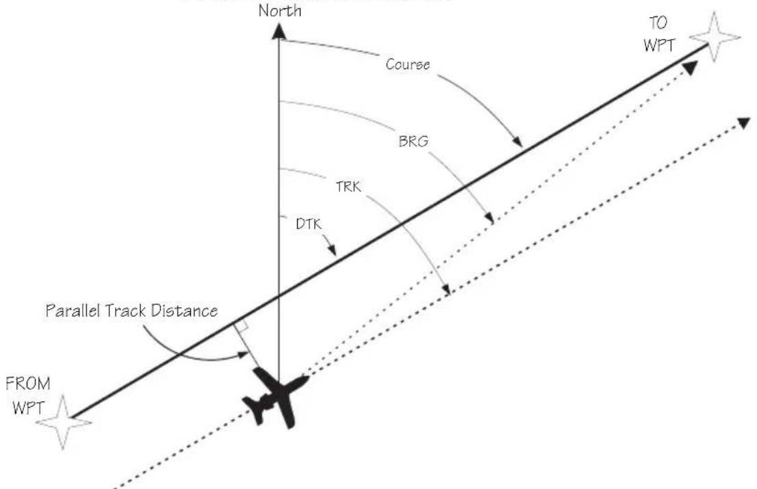
text_image
North Course BRG TRK DTK TO WPT Parallel Track Distance FROM WPTWhen Parallel Track is selected, the course line drawn on the Map pages will show the parallel course. If the Hold function is used when Parallel Track is selected, the Hold waypoint will be the phantom waypoint on the parallel offset, not the actual waypoint. Using Direct-To, loading an approach, or editing your flight plan will automatically cancel Parallel Track. A series of turns, even if less than 120^ , is not allowed if the “inside” parallel tracks would overlap.
Navigation Basics
- In the Nav function, turn the LARGE knob to display Parallel Track.
PARALLEL TRACK OFFSET: STANDBY RIGHT 12.4NM
SEL
ENTER

- Press SEL. The Offset field will flash. Two states are available: Use or Standby. If Parallel Track is in use, "Standby" will flash. If Parallel Track is on Standby, "Use?" will flash. If the direction and distance values are what you want, press ENTER. If you want to change the direction or distance, turn the LARGE knob to choose the direction or distance fields.
- After turning the LARGE knob to the direction field, turn the SMALL knob to choose Left or Right.
PARALLEL TRACK OFFSET: STANDBY LEFT 12.4MM

- Turn the LARGE knob to the distance field. Turn the SMALL knob to select the offset distance.
PARALLEL TRACK OFFSET: STANDBY LEFT 5.0 NM

text_image
ENTER MSG- Turn the LARGE knob back to the "Offset" field. Press ENTER when the "Use?" prompt flashes to activate Parallel Track. A "p" will appear next to the waypoint identifier to indicate that Parallel Track is in use. The MSG annunciator will flash and a message will state that Parallel Track is in use. Press MSG to view the message.
PARALLEL TRACK OFFSET: USE? LEFT 5.0NM
ETE PCVO 00:22 0.034 A BRC 186 46.1NMT
GPS Position
The GPS Position page shows the calculated Latitude and Longitude, as well as its Position Dilution of Precision (PDOP). The PDOP value, shown below "PDOP," is based on the geometry of the satellites used in the position solution. A lower number is a better value than a large one. A PDOP value of 3 will provide a more reliable position fix than a value of 7.

In the Navigation function, turn the LARGE knob to display the GPS Position page. The PDOP value is shown in the lower, right corner (1.9 is shown here).
GPS POSITION 44°10.11N PDOP 123°15.84W 1.9
Countdown Timer
The Countdown Timer allows you to set a timer that will alert you when it expires with a flashing MSG annunciator. The maximum time is 99:59:59 (hours, minutes, seconds). The default time on power up is the previous time that was entered. The factory default time is 00:03:00 (3 minutes). You can stop the timer by pressing SEL twice while viewing the Countdown Timer page.
- While in the Navigation function, turn the LARGE knob to view the Countdown Timer page.

- Press SEL to start editing. The minutes value will flash.
COUNTDOWN TIMER 00:03:00
- Turn the LARGE knob to move between the time value fields.
COUNTDOWN TIMER 00:03:00

- Turn the SMALL knob to edit the hours, minutes, or seconds value.
COUNTDOWN TIMER 01:03:00
ENTER
- Press ENTER to start the timer with the selected time value. You can press SEL to reset the timer back to the selected time.
MSG
- After the Countdown Timer value expires, press the MSG key to note the time out message.
Arc Assist The Arc Assist function will help you to navigate along an arc. In the GX50/60, Arc Assist will help you fly approaches with DME Arcs. Arc Assist can be used as a user-defined arc to avoid special use airspaces, or for conducting aerial searches using increasingly larger circles. The Arc Assist page shows the direction of the arc (left or right), the reference waypoint identifier, the desired track for the arc, and the distance to the reference waypoint.
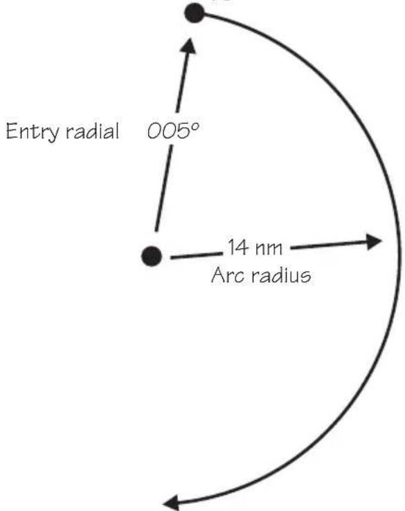
text_image
Entry radial 005° 14 nm Arc radiusENTER
SEL
The Arc Assist reference waypoint defaults to the nearest VOR unless you have already selected one. Press ENTER to accept the displayed reference waypoint. Press SEL to choose another reference waypoint.

ENTER
- In the Navigation function, turn the LARGE knob to reach the Arc Assist page. Press ENTER to accept the displayed reference waypoint and go to step 3 or choose another waypoint and go to step 2.
ARC ASSIST REF: UBG VOR PRESS ENT OR SEL
Navigation Basics

- Press SEL. Choose another waypoint using the LARGE and SMALL knobs.

text_image
VOR OVO CORVALLIS FACIL OR USA
- Select the Arc direction with the SMALL knob.
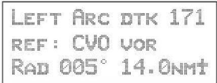
text_image
LEFT ARC DTK 171 REF: CVO VOR RAD 005° 14.0NMT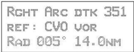
text_image
RIGHT ARC DTK 351 REF: CVO VOR RAD 005° 14.0NM
- Press ENTER to accept the selections and start navigating.

Note
The DTK on the Arc Assist page is the no-wind heading to hold the distance shown. It is a tangent to the current radial.
Other Uses for Arc Assist
You can select the reference waypoint for the Arc Assist feature and it can be used at any time, not just during approach or terminal operations. It can also be used for difficult operations such as conducting an over water search. By establishing a user waypoint at the center of such a search area and selecting that waypoint as a DME Arc reference point, you can fly circles about that waypoint at known distances. By gradually increasing the arc distance each time you pass a specific radial, you can expand the search area. The Arc Assist feature of the Apollo GX can make this much easier.
Waypoint Distance Page
This page shows the cumulative distance from your current position to each waypoint in the active flight plan starting with the active leg. Turn the SMALL knob to view the next set of waypoints in your active flight plan. The waypoint type is shown to the left of the identifier. The allowable waypoint types are: Airport (a), Intersection (i), NDB (n), and VOR (v). The waypoint type symbol will not be shown if one of the following occurs: the waypoint identifier is unknown, it is an approach waypoint that is not one of the four used types, it is a User waypoint, the waypoint is not recognized by the current data card's database, or the data card has been removed.
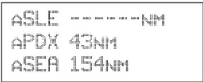
text_image
ASLE APDX 43NM ASEA 154NMWaypoint ETE Page
This page displays the cumulative time in hours and minutes from your current position to each waypoint in the active flight plan, starting with the active leg. Turn the SMALL knob to view the next page of waypoints. The time will not be shown for the same reasons as in the Waypoint Distance page.
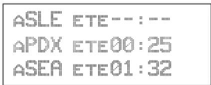
From-To-Nex t Waypoint ETA Page
This page displays the ETA for each waypoint in your active flight plan from your current position, starting with the active leg. Turn the SMALL knob to view the next page of waypoints. The time will not be shown for the same reasons as in the Waypoint Distance page, if the ground speed is zero, or if 3-D positioning is lost.

text_image
ASLE ETA: : : : APDX ETA12: 15 ASEA ETA13: 32From/To/Next Waypoint
The FROM/TO/NEXT Waypoint allows you to view and/or edit a three waypoint mini-flight plan, or view two legs of your flight plan, while within the Nav function. These waypoints are like a three waypoint window into your Active Flight Plan. Changes to the FROM/TO/NEXT page change the Active Flight Plan, and vice versa. You may also Hold (sequencing suspended) or enable the TO waypoint.
Note
Your flight plan will be placed on Hold while you are editing the FROM/TO/NEXT waypoints.
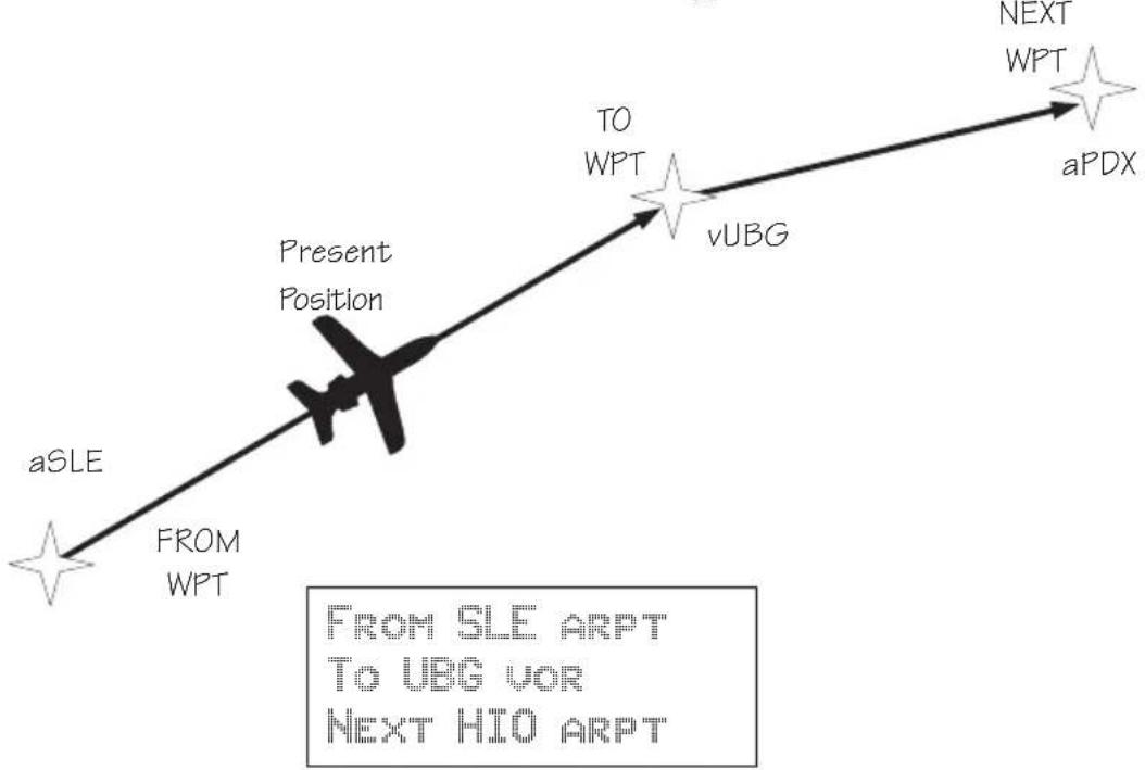
flowchart
graph LR
    A["aSLE"] -->|FROM WPT| B["Present Position"]
    B --> C["vUBG"]
    C --> D["NEXT WPT"]
    D --> E["aPDX"]
    style A fill:#f9f,stroke:#333
    style B fill:#ccf,stroke:#333
    style C fill:#cfc,stroke:#333
    style D fill:#fcc,stroke:#333
    style E fill:#cff,stroke:#333
Creating FROM/TO/NEXT Waypoints
A - Set the FROM Waypoint

- While in the Navigation function, turn the LARGE knob to view the FROM/TO/NEXT page.
FROM TO NEXT
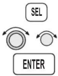
flowchart
graph TD
    A["SEL"] --> B((Circular Process))
    B --> C["ENTER"]
    C --> A
- Press SEL to start editing. Turn the LARGE knob to select the FROM (first) waypoint position. Turn the SMALL knob, if necessary, so the flashing selection shows "Ins?" (Insert). Press ENTER.

- The Waypoint Type will flash. Choose the Waypoint Type with the SMALL knob.

text_image
AIRPORT AAF APALACHIOCOLA CITY FL USA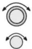
- Turn the LARGE knob to the first character of the waypoint name. The first character of the waypoint name will flash. Turn the SMALL knob to select the desired character.

text_image
AIRPORT EAA EAGLE CITY AK USA
- Turn the LARGE knob clockwise one click to move to the next character. Turn the SMALL knob to select the desired character. Continue to select additional characters.

text_image
AIRPORT EUF_ EUFAULA CITY AL USANavigation Basics

- Turn the LARGE knob clockwise one click to move to the next character. Turn the SMALL knob to select the desired character. Continue to select the needed characters.
AIRPORT EUG EUGENE CITY OR USA
ENTER
- Press ENTER when you have selected the desired waypoint.
FROM EUG ARPT TO NEXT
B - Set the TO Waypoint
SEL
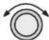
- Press SEL and move to the TO waypoint with the LARGE knob. The insert (Ins?) choice will flash. Press ENTER and then select the TO waypoint as you did for the FROM waypoint.
ENTER
FROM EUG ARPT TO INS? NEXT
ENTER
- After selecting a TO waypoint, press ENTER.
FROM EUG ARPT TO SLE NEXT
C - Set the NEXT Waypoint
SEL

ENTER
- Press SEL and move to the NEXT waypoint with the LARGE knob. The insert (Ins?) choice will flash. Press ENTER and then select the NEXT waypoint as you did for the FROM and TO waypoints.
FROM EUG ARPT TO SLE NEXT INS?
ENTER
- After selecting a NEXT waypoint, press ENTER.
FROM ENG ARPT TO SLE ARPT NEXT HIO ARPT
D - Editing FROM/TO/NEXT Waypoints

SEL
- While in the Navigation function, turn the LARGE knob to view the FROM/TO/NEXT page. Press SEL to start editing.
FROM EUG ARPT TO SLE ARPT NEXT CHG? ARPT
- Turn the LARGE knob to select the FROM, TO, or NEXT waypoint field to edit.
FROM EUG ARPT TO CHG? ARPT NEXT HIO ARPT
Navigation Basics

ENTER
- Turn the SMALL knob to choose the type of editing you want to do. The flashing selection will ask you to choose between Ins (Insert), Chg (Change), or Del (Delete). The TO waypoint can also be placed on Hold. Press ENTER when you have selected the editing option. When a waypoint is deleted, its position will be replaced by dashes. The Chg and Ins choices will allow you to select a new waypoint as used in the previous examples.
SEL
Placing the TO Waypoint on Hold
- Press SEL and move to the TO designation with the LARGE knob. You can also place the TO waypoint on hold by pressing the external WPT SEQ (or GPS/SEQ) button, when it is installed. You can also place a waypoint on Hold in the Flight Plan or FROM/TO/NEXT functions. The HOLD annunciator will light when it is installed to indicate that automatic waypoint sequencing is suspended.
FROM EUG ARPT HOLD?SLE ARPT NEXT HID ARPT

- Turn the SMALL knob to choose "Hold?" or "To?" Placing the TO waypoint on Hold suspends waypoint sequencing.
FROM EUG ARPT TOP SLE ARPT NEXT HIO ARPT
ENTER
- Press ENTER.
FROM EUG ARPT HOLD SLE ARPT NEXT HIO ARPT
Reverse the operation to return to normal sequencing.
Using Direct-To
Pressing the DIRECT-TO key sets your present position as the FROM location. When using the Direct-To function, the FROM waypoint identifier is overwritten with the word “Direct.” If you remove the Direct-To position with the Del? option, the old FROM waypoint is returned to that position. If you edit the FROM position, Direct-To navigation will be replaced by the new entered waypoint.

flowchart
graph TD
    A["Present Position"] --> B["From WPT"]
    B --> C["TO WPT"]
    C --> D["Direct-To Route"]
    D --> E["Direct-To Waypoint"]
Direct-To Defaults
When you press DIRECT-TO, the default waypoint shown will be the current TO waypoint in the Nav or Flight Plan functions or the waypoint displayed in the Database or Info functions.
| Function DIRECT-TO Waypoint Default | |
| Nav | Current TO waypoint |
| Database | Displayed waypoint |
| Flight Plan | Displayed leg TO waypoint |
| Info | Displayed waypoint |
You can always select a different Direct-To waypoint, but the default is a useful starting point. While viewing the default waypoint, press DIRECT-TO and then ENTER to navigate directly to that waypoint.
Direct-To Operation
- Press the DIRECT-TO key. The waypoint type will flash.

AIRPORT HIO PORTLAND CITY OR USA
- Select the new destination (TO) waypoint using the SMALL and LARGE knobs.

AIRPORT HMV MC MINNVILLE CITY OR USA
ENTER
Direct-To Examples
- Press ENTER.
The following three examples provide some of the more common ways that you can use the powerful Direct-To function.
Center the CDI
After changing your course to avoid weather, an obstacle, or being directed, you may need to reset your course to center your CDI to continue navigating to your intended TO waypoint.

flowchart
graph TD
    A["EUG"] --> B["Leg 1"]
    B --> C["SLE"]
    C --> D["LL"]
    D --> E["MMY"]
    style A fill:#f9f,stroke:#333
    style B fill:#ccf,stroke:#333
    style C fill:#cfc,stroke:#333
    style D fill:#fcc,stroke:#333
    style E fill:#cff,stroke:#333

- You flew to the right to avoid a storm cloud and your CDI tells you to fly left, but you still have the same TO waypoint. Press DIRECT-TO. Your current TO waypoint is displayed and the Waypoint Type will flash.

text_image
AIRPORT SALE SALEM CITY OR USA
- Press ENTER. You will now fly direct from your present position to your desired TO waypoint. Your CDI will now be centered, as you are “on course.”
Enter a New Waypoint into a Flight Plan
While on a flight plan, you may want to temporarily go to a new waypoint to look at something or you may be directed by ATC. By using Direct-To, you can add this new waypoint into your existing flight plan. This way your flight plan is essentially unchanged, but you were still able to react quickly to new conditions.

Note
Make sure your Direct-To Entry Option is set to "Never Clears," or your active flight plan will be deleted if the Direct-To waypoint isn't in your active flight plan. See page 7-8 for details.

flowchart
graph TD
    A["Before Adding Direct-To Waypoint"] --> B["HIO"]
    B --> C["Leg 2"]
    C --> D["DLS"]
    E["After Adding Direct-To Waypoint"] --> F["HIO"]
    F --> G["Leg 3"]
    G --> H["DLS"]
    I["MMV"] --> J["Leg 1"]
    J --> K["SLE"]
    L["MMV (Direct-To Waypoint)"] --> M["Leg 2"]
    M --> N["SLE"]
    O["MMV"] --> P["Leg 1"]
    P --> Q["SLE"]
Navigation Basics


- While on the first leg of your active flight plan, you find out that you need to make another stop on the way but you don't want to change the rest of your plan. Press FPL. While viewing the Active flight plan, turn the SMALL knob to the first leg.
SLE TO HIO 1xxx 345° 37.8NM ARPT ARPT


- Press DIRECT-TO. Select the desired waypoint using the LARGE and SMALL knobs.
AIRPORT HMV MC MINNVILLE CITY OR USA

- Press ENTER. The Nav function will now be displayed with your new TO waypoint (MMV).
ETE AMNV 00:20 0.011 △ BRC 321 15.6NMT


- Check your active flight plan pages. Press FPL. Turn the SMALL knob, if necessary. Note that your current leg now shows a direct flight to MMV.
DIRECT TO MMV 1xx 321° 16.5NM " ARPT

- Turn the SMALL knob one click cw to check the next leg. Note that your flight plan continues to HIO as your original plan did. You have inserted a new leg using the Direct-To function.
HIV TO HIO 2x 003° 22.2NM ARPT ARPT
Direct-To OBS
Pressing the DIRECT-TO key twice starts the OBS desired track editor. OBS Desired Track allows entry of a desired track to or from the current TO waypoint. The current desired track in the navigation pages will be replaced by the OBS Desired Track value entered. You may also select the reference waypoint from your active flight plan. Waypoint sequencing is normally set as manual. When an approach is enabled, you may select either manual or automatic. You may wish to select manual sequencing so you may disable sequencing if you will be in a holding pattern that will cause you to continually cross the TO waypoint.
When your GX is configured to receive information from the SL30 Nav/Comm, the OBS Desired Track field is coupled to your HSI/CDI. Your HSI/CDI is being read by the SL30 at the same time. Rotating the control on your HSI/CDI will update the OBS Desired Track on your Apollo GX. You can override the HSI/CDI input to your Apollo GX by using the concentric knobs of the GX as described below.

- Press DIRECT-TO twice. The first character of the Desired Track value will flash. Turn the SMALL knob to change the value.

text_image
OBS DTK: 100° MHV ARPT MAN BRC 000 DTK 000

- Turn the LARGE knob to move to the next character. Turn the SMALL knob to change the value. You may also select the reference waypoint from your flight plan waypoints.

text_image
OBS DTK: 115° HMV ARPT MAN BRC 000 DTK 000- When an approach is enabled, you may also select between manual or automatic waypoint sequencing. Setting sequencing to manual is useful in the case where a holding pattern would allow frequent sequencing and waypoint alerts.
ENTER
Turn Anticipation
- Press ENTER when the choices are selected.
The Apollo GX will provide information for you to smoothly transition from one flight plan leg to another. Turns are drawn on the moving map. You will receive a message about ten seconds before the turn. The message will count down to the beginning of the turn. The message shown below indicates that you are arriving at the SLE waypoint, the next leg desired track is 93^ , and you should start your turn in about nine seconds.
ARRIVAL: SLE DTK 093° START TURN IN 9
Standard Turn Operation
While you are in the turn, the desired track and cross track are determined based on the turn. Turns are made at three degrees per second if the ground speed is under 250 knots. If ground speed is greater than 250 knots, the turn rate is set at 1.5 degrees per second.

text_image
SLE 44S 785° 30 24.2 Aircraft Present Position SLE 684° Route Line Turn Anticipation Curves If turn angle is greater than 120°, the turn will start well before reaching the waypointTurn anticipation is not shown if the end of the turn extends beyond the beginning of the next anticipated turn. That is, if the two waypoints are too close, turn anticipation will not be shown. Turn anticipation curves are only drawn when the turn is greater than 5^ . If the turn is greater than 120^ , the Apollo GX will generate a step turn message prior to the waypoint.
Turn anticipation will not be available when sequencing is on Hold; for the MAP or MAHP of an approach; or for the “flyover” waypoints in an approach.
Wind and Turn Anticipation
The graphic Turn Anticipation curve drawn on the map display is based on your current ground speed. Once you enter the turn, the graphic curve is no longer updated. You may need to increase or decrease your standard rate turn to compensate for wind. If your installation includes a GPSS autopilot interface, the Apollo GX will monitor your progress throughout the turn and send corrections to the autopilot. Wind conditions requiring steeper than maximum bank angles may result in overshooting the new course line.
GPSS GPS Steering (GPSS) information is provided by your Apollo GX when setup with a properly installed autopilot. An autopilot guided by information from your Apollo GX will be more accurate, faster responding, and smoother than using a CDI. GPSS works with the Flight Plan and Turn Anticipation features to have your avionic equipment do more of the work for you.
Standard GPSS Operation
Operating your Apollo GX with an autopilot is simple:
1) Select a waypoint or flight plan in the Apollo GX.
2) Select GPSS mode on the autopilot or on the HDG/GPSS selector switch (see your autopilot operating instructions).
3) Fly. Your Apollo GX will direct the autopilot.
Approach GPSS Operation
When the autopilot is directed by GPSS, there are few considerations when flying an approach.
- GPSS information will not be provided after you pass the MAP. You need to follow the directions published on the approach plate.
- When directed to the MAHP, use the Direct-To function. GPSS information will now once again be provided to the autopilot.
- Certain waypoints within an approach may be coded as “Fly-over” waypoints. Fly-over waypoints must be overflown before starting your turn to the next waypoint. A turn anticipation curve will not be drawn for these Fly-over waypoints. The GPSS information from your Apollo GX will handle this automatically.
GPSS Rules
There a few rules for providing valid GPSS information to your autopilot. Your autopilot should indicate when GPSS information is valid/invalid.
Refer to your autopilot operating instructions for details.
Apollo GX Information
- Your ground speed must be more than 5 kts
- You are navigating to a waypoint (flight plan or direct-to)
• You are on the TO side of the waypoint
• You are not executing Missed Approach procedures
Autopilot Information
• Horizontal bank output from the Apollo GX to the autopilot is limited to 30^ or less
- Turn rate is 3^ / sec at speeds less than 250 kts - Turn rate is 1.5^ / sec at speeds greater than 250 kts
Tuned Station
When your Apollo GX is connected to and configured to communicate with an Apollo SL30 Nav/Comm, your Apollo GX will provide information about the VOR or Localizer tuned by the SL30. The Apollo SL30 with SW version 1.2, or later, sends the Tuned Station information once every second. Earlier versions of the SL30 only sends data when the frequency is changed. If the Apollo GX shows a different frequency than is shown on the SL30, press the F/F key on the SL30 to synchronize the units.
Reach the Tuned Station display, as shown below, by pressing NAV and turning the LARGE knob. The tuned station identifier and its frequency are shown, as well as the distance to it from your present position and your current ground speed. The Distance, Speed, and Time to waypoint information is sent by the Apollo GX for display on your Apollo SL30. The pilot should verify the station identification prior to navigation use.
31 000 32 000 33 000 34 000 35 000 36 000 37 000 38 000 39 000 40 000 41 000 42 000 43 000 44 000 45 000 46 000 47 000 48 000 49 000 50 000 51 000 52 000 53 000 54 000 55 000 56 000 57 000 58 000 59 000 60 000 61 000 62 000 63 000 64 000 65 000 66 000 67 000 68 000 69 000 70 000 71 000 72 000 73 000 74 000 75 000 76 000 77 000 78 000 79 000 80 000 81 000 82 000 83 000 84 000 85 000 86 000 87 000 88 000 89 000 90 000 91 000 92 000 93 000 94 000 95 000 96 000 97 000 98 000 99 000
F. 10: 17: 9:
13.55NM 200KTS
Tuning to a VOR
The selected VOR frequency on the SL30 is sent to your Apollo GX. The Apollo GX searches its database for a unique identifier for that frequency within 200 nm of your position. If a unique match is found, the selected VOR identifier, frequency, the distance from your present position, and your ground speed are shown on the Apollo GX display. The Apollo GX will send Distance, Speed, and Time to waypoint information to the SL30. If no frequency is found, or two or more are found, within 200 nm, no information will be displayed. All VORs are utilized, even those without TACAN or DME. Once a VOR is identified it will continue to be tracked even beyond 200 nm.
Tuning to a Localizer
When the connected SL30 is tuned to a Localizer frequency, the SL30 sends the decoded Localizer identifier to the Apollo GX. The Apollo GX searches its LOC-DME database for an identifier match. If the Localizer is found to be a co-located LOC-DME, the Apollo GX will provide Distance, Speed, and Time information to the SL30 and for the Tuned Station page on the GX.
Moving Map Functions
Press the MAP key to reach the Moving Map function and view the progress of your flight on a graphic display. Your present position, nearby waypoints, and special use airspaces display options are user-selectable. Three main pages are available in the Moving Map function: full screen map, split screen with map and Nav info, Search & Rescue (SAR) when selected, and map setups.
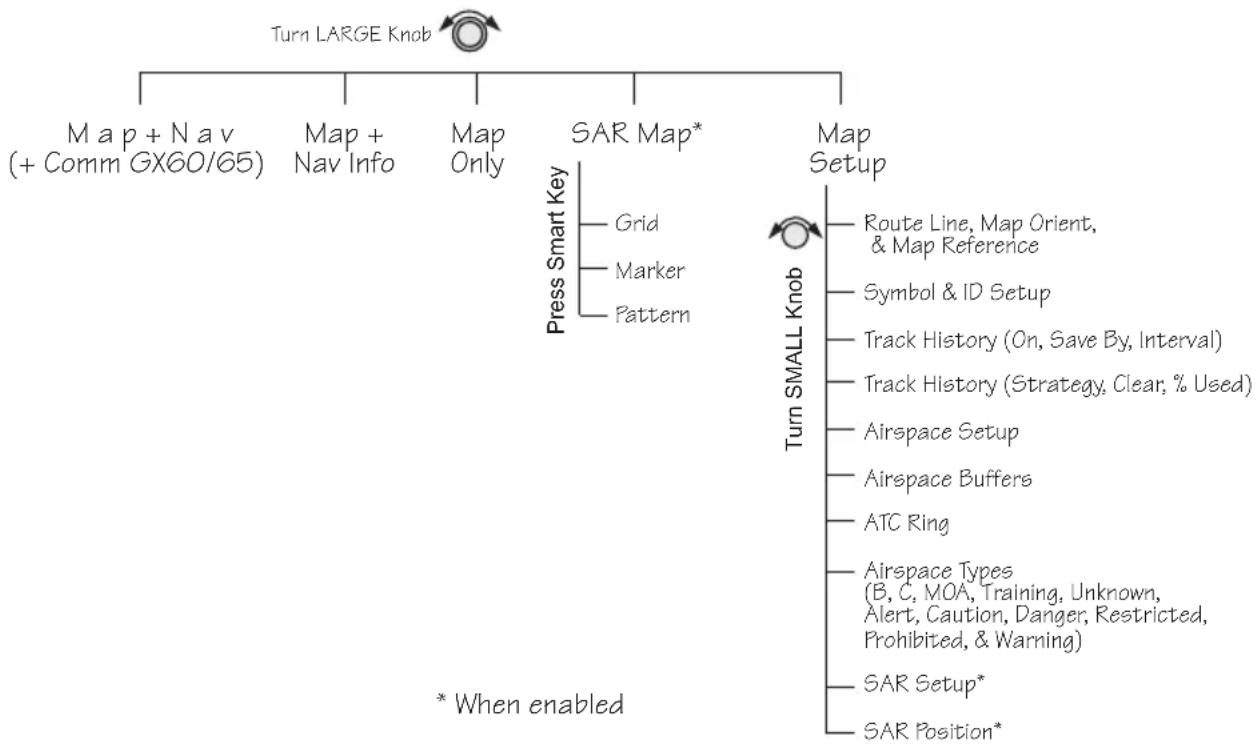
flowchart
graph TD
    A["Turn LARGE Knob"] --> B["Map + Nav (+ Comm GX60/65)"]
    A --> C["Map + Nav Info"]
    A --> D["Map Only"]
    A --> E["SAR Map*"]
    A --> F["Map Setup"]
    E --> G["Press Smart Key"]
    G --> H["Grid"]
    G --> I["Marker"]
    G --> J["Pattern"]
    K["Turn SMALL Knob"] --> L["Route Line, Map Orient, & Map Reference"]
    K --> M["Symbol & ID Setup"]
    K --> N["Track History (On, Save By, Interval)"]
    K --> O["Track History (Strategy, Clear, % Used)"]
    K --> P["Airspace Setup"]
    K --> Q["Airspace Buffers"]
    K --> R["ATC Ring"]
    K --> S["Airspace Types (B, C, MOA, Training, Unknown, Alert, Caution, Danger, Restricted, Prohibited, & Warning)"]
    K --> T["SAR Setup*"]
    K --> U["SAR Position*"]
    V["* When enabled"] --> W
Full Screen Map
The full screen map page of the Moving Map function shows a graphic map of the aircraft position, nearby user-selected waypoints, airspaces, track history, and your route. The aircraft position is shown by an airplane symbol near the center of the display. The TO waypoint identifier is shown in reversed text on the upper left corner. The bearing from your current position to the TO waypoint is shown on the upper right corner. The map scale is shown in the lower left corner. The distance from the current position to the TO waypoint is shown in the lower right corner. A 5 n m “ATC Ring” can be drawn around airports that have a control tower.

text_image
TO Waypoint Identifier Route Line Waypoint Location Symbol Map Scale Special Use Airspace Sector P1X HIO 7S3 236 052 4: 7S9 MMV 20 SLE 805° Special Use Airspace Outer Ring Bearing to the TO Waypoint ATC Ring - approx. 5 nm Radius Distance to the TO Waypoint Waypoint Identifier Present Position SymbolControls
The LARGE knob moves to different pages of the Map function and selects waypoints when scanning. The SMALL knob changes the map scale.
Waypoint Type Keys
The smart keys select the display of the waypoint types. The waypoint types selectable from the map view are: Airports, VORs, Intersections, User-defined, and NDBs. Press the smart key to control the display of the waypoint type. There are three selections possible: waypoint identifier and location symbol, location symbol only, and off. Pressing the smart key subsequent times will control which selection is made. The change will also be displayed on the map setup pages.
APT
A solid, reversed waypoint type annunciator above the smart key means the waypoint identifier and location symbol will both be displayed. A bold outline of the waypoint type annunciator will show only a symbol on the waypoint location. A thin outline around the waypoint type means that it is turned off and no information for that waypoint type will be displayed on the map.
APT
Waypoint List Keys
APT
The Waypoint List smart key shows a number. Press the key to scroll through the list of available waypoint types available for selection.
Waypoint Scan Key
The Waypoint Scan smart key allows you to select an airport to get information about while viewing the map.
SCAN

INFO
- Press the SCAN smart key.
- Turn the LARGE knob to highlight the desired waypoint identifier.
- Press INFO to get information about the waypoint. Press INFO to return to the map display. You may also press DIRECT-TO and then ENTER to go direct-to the highlighted airport.
- Press the SCAN key again to return the LARGE knob to normal operation.
SCAN
Map Scale
The Map Scaling is controlled by turning the SMALL knob while viewing the map. The map scale value shown is the vertical height of the screen in nautical miles. Map scale choices in nautical miles are: 0.1, 0.2, 0.5, 1, 2, 5, 10, 15, 20, 30, 40, 50, 75, 100, 150, 200, 250, and auto. The auto selection automatically adjusts the map scale so the “TO” remains on the display until the aircraft passes over the waypoint.
MAP

Map and Nav Info
- Press MAP.
- Turn the SMALL knob to adjust the map scale.
- Turn the LARGE knob to view the other Map function displays.
The Map and Nav Info page of the Map function provides a split screen showing the moving map and selected navigation information. The navigation information provided on the right side of the display includes: the current TO waypoint identifier, distance and bearing to the TO waypoint from your current position, ground speed, aircraft current track, and the map scale.

text_image
Special Use Airspace Distance to the TO Waypoint TO Waypoint Identifier Ground Speed Route Line Your Present Position Cross Track Error Distance & Direction 44.2 123 NM KT 005 ↑ 006 BRO TRK 0.01 > 30 Bearing to the TO Waypoint Current Track Map ScaleMap Setup
The map setup function allows you to select the route line, map orientation, waypoint types that will be displayed, airspace type, and special use airspaces, as well as what airspace alerts will appear when an airspace is penetrated.
Route Line
A Route Line can be drawn for the legs of the active route when the selection is turned on. A route line is not drawn for procedure turns.

text_image
TO Waypoint Identifier m654 ATC Ring Route Line 093 Bearing to the TO Waypoint 443 795 S1E 654 Route Line Distance to the TO Waypoint Map Scale 30 24.2
flowchart
graph TD
    A["Circle with Arrows"] --> B["SEL"]
    B --> C["Circle with Arrows"]
    C --> D["RTE"]
- In the Map function, turn the LARGE knob to reach the Map Setup page. Press SEL to start selection of the Route Line. The Route Line selection will flash. Or, press the RTE smart key to toggle through the choices.

text_image
ROUTE LINE:ON MAP ORIENT:NORTH MAP REF:PLANE T
ENTER

- Turn the SMALL knob to choose On or Off.
- Press ENTER when you made your selection, or turn the LARGE knob to the next item.
Map Orient
The Map Orient selection allows you to choose how the top of the map display is oriented.
North Up - The display is oriented so that vertical lines on the map are aligned with magnetic north. The aircraft symbol is centered in the display and will point towards the direction you are flying.
DTK Up - The Desired Track for the current flight plan leg is the top of the display. The aircraft symbol is at the bottom of the display and will point towards the direction you are flying.
Track Up - The direction that your aircraft is moving towards is at the top of the display. The aircraft symbol is at the bottom of the display.
- Turn the SMALL knob to choose North, DTK, or Track.
- Press ENTER when you made your selection, or turn the LARGE knob to the next item.

SEL
ORI

ENTER

Map Reference
The Map Reference selection allows you to choose either the Destination Waypoint (Dest) or your current position with an airplane icon (Plane) as the center point of the Moving Map display.

SEL

REF
- In the Map function, turn the LARGE knob to reach the Map Setup page. Press SEL. The value will flash. Turn the LARGE knob to choose Map Ref for selection. Or, press the Map Reference (REF) smart key to toggle through the choices.
ROUTE LINE: ON MAP ORIENT: NORTH MAP REF: PLANE +

ENTER
- Turn the SMALL knob to choose Dest or Plane. Press ENTER after completing your choices. It is not necessary to press ENTER if you used the smart key.
Identifier and Waypoint Type Selection
The Identifier & Waypoint Type page allows you to choose the type of waypoint identifiers that will be displayed on the moving map. You may control the look of your map screen for each type of waypoint by choosing to show the symbol and Identifier, symbol only, or to turn that type of waypoint “Off.” The symbol for each waypoint type is shown in each selection. When “Off” is selected, no symbol or identifier will be displayed for that waypoint type. You may use the “smart” keys to toggle through the selections. The “smart” keys always allow you to select their waypoint type while viewing the MAP display. Note that an airport with a runway of 0 length will not appear on either the nearest list, or on the map if a length is set for the runway limit. See page 3-12 for details on Runway Limits.
Note
Waypoints that are in an active flight plan will show up on the moving map even if its waypoint type is set as "Off."


- In the Map function, turn the LARGE knob to reach the Map Setup page. Turn the SMALL knob to the Identifier & Waypoint Type page. Press SEL to start editing the waypoint types.
APT: ID INT: +ID
VOR: AID NDB: ×ID
USR: =ID


- Turn the LARGE knob to choose the waypoint type that you want to edit. Turn the SMALL knob to choose symbol and identifier (ID), symbol only, or "Off." In this example, the flashing (underlined) selection would show both the symbol and identifier for intersections.
APT: AID INT: AID
VOR: AID MDB: XID
USR: AID

- Turn the SMALL knob to select the combination you want shown on the Map display. In this example, only the symbol ( ++ ) will be shown on the Map display for Intersections.
APT: #ID INT: +_
VOR: AID NDB: XID
USR: #ID
ENTER

- Press ENTER when you have completed your selections, or turn the LARGE knob to the next item.
Track History
Your Apollo GX can store a record of its progress in memory that will be shown on the display. The Track History is shown as a series of points on the display following the path of the plane icon. Track history may be recorded by time or by distance at a selected interval. You may also select the Strategy for storing the track history points. The Full strategy choice means that track points will be stored until memory is full. Subsequent track points will not be stored. The Forever strategy will overwrite previous track points when memory is full. The Clear Track selection allows you to clear the existing track history memory whenever you select Yes. The %used value shows the percentage of track history used.
Track History Recording Points

text_image
0136 1.684 + 1 6.52Track History function has two pages where you may set the following options:
• Track History On/Off
• Save by Distance/Time
• Interval for saving Track History
• Strategy (Full/Forever)
• Percentage of memory used (status only)
- In the Map function, turn the LARGE knob to reach the Map Setup page. Turn the SMALL knob to the first Track History page. Press SEL to start editing the waypoint types. Pressing the TRK and SAV smart keys toggle the available options. Pressing the INTV smart key enables selection of the interval value.
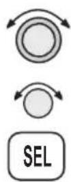
TRK HISTORY:OFF SAVE BY: DISTANCE INTERVAL:0.5
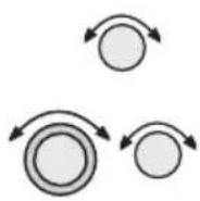

- Turn the SMALL knob to select On or Off.
- Turn the LARGE knob to the Save By option. Turn the SMALL knob to choose Distance or Time.
- Turn the LARGE knob to the Interval option. Turn the SMALL knob to choose the Interval value. If you chose to Save By Distance, select a distance between 0.1 and 10.0 nm. If you chose Save By Time, select a time between 1 sec. (00:01) and 10 minutes (10:00).
- Press ENTER when you have completed your selections.
- Turn the SMALL knob clockwise to the second Track History page. Press SEL to start selection or press the appropriate smart key. The Strategy value will flash. Turn the SMALL knob to change the value.
STRATEGY: FULL CLEAR TRACK: NO %USED: 12


- Turn the LARGE knob to the Clear Track option. Turn the SMALL knob to choose Yes to clear (delete) existing Track History or No to leave existing Track History in place. If you select Yes for Clear Track, the %used value will return to zero.
- Press ENTER when you have completed your selections.
ENTER
Airspace Setup
The Airspace Setup selections allows you to turn Airspace notification (Alerts) or map display of Airspaces On or Off, select the distance and time buffers for airspace alerts, turn ATC rings On or Off, and to choose the Airspace types that will be used. Airspace alerts will not be given during an approach.
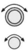
- In the Map function, turn the LARGE knob to reach the Route Line/Map Orient page. Then, turn the SMALL knob two clicks clockwise. The Airspace Setup page is shown.
HIRSPACE SETUP
- Turn the SMALL knob to view the pages for Airspace Setup. On this page you may select whether Airspaces are shown on the Map display or whether Airspace Alerts are provided. Press SEL to start selection. The Map choice will flash. Turn the SMALL knob to select On or Off. The Map (MAP) and Alert (ALE) “smart” keys also select the options.
AIRSPACE SETUP
MAP : OFF
Alerts: OFF
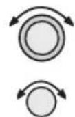
- Turn the LARGE knob to move to the Alerts choice. This sets the Alert value for all airspaces. If set to ON, each airspace alert may be set separately. Setting Alerts OFF turns off all airspace alerts. Turn the SMALL knob to select On or Off. Press ENTER after completing your choices. Airspace alerts are automatically disabled when an approach is enabled.
ENTER
AIRSPACE SETUP
Map : ON
- 2017年1月1日
Airspace Buffers
Three values may be adjusted for Airspace Buffers for determining CLOSE information: distance, elevation, and time. CLOSE distance may be from 0 to 99 nm at one nm intervals. Altitude values are from 0 to 9900 feet in 100 foot intervals. Time values are from 0 to 20 minutes in one minute intervals. From the Map Setup page, turn the SMALL knob three clicks cw to reach the Airspace Buffers page.
SEL
- While viewing the Airspace Buffer page, press SEL. The distance value will flash.
AIRSPACE BUFFERS DIST ALT TIME 2NM 500" 10MIN
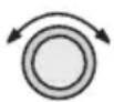
- Turn the LARGE knob to select the desired value to change. Turn the SMALL knob to change the value.

AIRSPACE BUFFERS DIST ALT TIME 2NM 500' 10MIN
- Press ENTER when the desired values have been selected.
ENTER
AIRSPACE BUFFERS DIST ALT TIME 2NM 200' 10MIN
ATC Ring Selection
When this choice is turned ON, a 5 n m r a d i u s artificial “ATC Ring” is drawn on the Map display around airports that have a control tower. From the Map Setup page, turn the SMALL knob four clicks cw to reach the ATC Ring selection page.
SEL
- While viewing the ATC Ring page, press SEL to start selection.
5 MM ATC KINGS Map : Off

ENTER
- Turn the SMALL knob to choose ON or OFF. Press ENTER after completing your selection.
5 NM ATC RINGS MAP : ON
Airspace Selections
The Airspaces available for selection are: Class B (Off, Outer, or Sector), Class C (Off, Outer, or Sector), MOA, Training, Unknown, Alert, Caution, Danger, Restricted, Prohibited, and Warning. You may select ON or OFF for map display and alerts for each Airspace type.

text_image
Outer SectorThe Outer selection refers to the outline of the outside ring extended from the ground on up. Selecting Outer will be useful to VFR pilots who wish to avoid all airspaces. The sector selection refers to the outside edges of the sector from the ground on up unless you have altitude input which then allows for
3-dimensional information. The Sector selection is the default setting and is most useful for IFR flight. An airspace will appear in the Nearest list even if the map or alert selections are set to off. The Map (MAP) and Alert (ALE) “smart” keys also select the options.

- While viewing the Map Setup page, turn the SMALL knob to the Airspace Setup page. Turn the SMALL knob to view the desired Airspace selection page.

text_image
CLASS B AIRSPACE MAP : OFF ALERT : OFF
- Press SEL to activate selection. Turn the SMALL knob to change the selection.

text_image
CLASS B AIRSPACE MAP : SECTOR ALERT : OFF
- Turn the LARGE knob to move to the next selection. Turn the SMALL knob to select your choice.
text_image
CLASS B AIRSPACE MAP : SECTOR ALERT : OUTER
- Press ENTER after making the selection. Turn the SMALL knob to view the other Airspace pages.
Search and Rescue
When activated, the Search and Rescue (SAR) feature allows a simplified, automated method of performing search patterns. The search patterns supported include parallel line, creeping line, and expanding square. A line showing the route of the pattern may also be displayed on the screen of your GX. Patterns can be based on two grid types: acronautical sectional charts (US) and a Lat/Lon grid system (Basic). The grid system can be displayed on the Moving Map, as well as the search pattern.
Search and Rescue Map Description
The Search and Rescue map page is essentially the same as the regular full map with the addition of the SAR features. However, at various zoom levels, underlying waypoint information will not be shown to allow for the display of SAR information. Smart keys control the Grid Lines (GRD), mark a position with a new User waypoint (MRK), and select a search pattern (PAT).

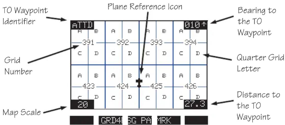
text_image
TO Waypoint Identifier Plane Reference Icon Bearing to the TO Waypoint ATTD 391 392 393 394 C D C D C D C D Grid Number A B A B A B A B 423 424 425 426 C D C D C D C D Map Scale 20 27.3 GRD4 SG PA MRKGrid Line Display
While viewing the Search and Rescue (SAR) map page, you can choose how the grid lines are displayed. Press the GRD smart key to change the Grid line view. Grid line selection options are slightly different for the two grid types, US and Basic. As you zoom out to approximately 40nm the grid lines will be removed.
US Grid Type
The US Grid selection is based on sectional charts as shown in the Sectional chart table.
GRD - No grid lines
GRD 1 - Section lines
GRD 2 - Section lines and section number
GRD 3 - Section lines, section number, and quarter section lines
GRD 4 - Section lines, section number, quarter section lines, and quarter section letters
GRID1

text_image
ATTD ■SAR000 ■SAR003 ■SAR002 20 27.3Map Display
Grid Lines
No Grid Number
GRID2

scatter
| Label | X | Y | |---|---|---| | SNR000 | 392391 | 394398 | | SNR003 | 425424 | 425428 | | SNR002 | 425424 | 425428 | | 20 | 425428 | 27.3 |Map Display
Grid Lines
Grid Numbers
GRID3

text_image
ATTQ 392394 894396 SNF000 SNF003 SNF002 425424 426428 20 27.3Map Display
Grid Lines
Grid Numbers
Quarter Grid Lines
GRID4
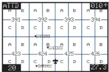
text_image
ATTD A B A B A B A B 391 392 393 394 C D C D C D C D A B A B A B A B 423 424 425 426 C D C D C D C D 20 27.3Map Display
Grid Lines
Grid Numbers
Quarter Grid Lines
Quarter Grid Letters
Basic Grid Type
GRD - No grid lines
GRD 1-60 minute grid lines
G R D 2 - 3 0 minute grid lines
GRD 3-15 minute grid lines

text_image
124° 123° 46° A B A B C D C D 30' A B A B C D C D 15' C D C D 45° 30' 15'Search and Rescue Map Setup Page
The SAR Map Setup page provides selection of SAR Map (Off/On), Grid Type (US/Basic), and the Position (area of operation).

- From the Map Setup Page, turn the SMALL knob counterclockwise two clicks to the SAR Map Setup page.
- Press SEL to allow selection of the Search and Rescue feature. Turn the SMALL knob to set the SAR Map value to ON or OFF. When SAR Map is set to ON, the SAR Map will be available. When set to OFF, the SAR Map will not be shown. The SAR smart key toggles SAR Map On or Off.

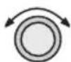
- Turn the LARGE knob to Grid Type. Turn the SMALL knob to choose US or Basic. The US Grid Type Position is based on sectional aeronautical chart grids. The Basic Grid Position is based on Lat/Lon positions. The GRD smart key toggles between US or Basic.

- Turn the LARGE knob to Position. Turn the SMALL knob to choose the position information. If you selected the US Grid type, choose the desired sectional name with the SMALL knob or the POS smart key. See the following Sectional Aeronautical Chart Grids table for the location nearest you operation.

For the Basic Grid type, select the Position quadrant (NW, SW, NE, or SE) with the SMALL knob or the POS smart key. Quadrant lines are defined by the Equator, Prime Meridian, and the International Date Line. For example, the continental U.S. Would be in the NW quadrant, Denmark would be in the NE quadrant, Buenos Aires, Argentina is in the SW quadrant, and Riyadh, Saudi Arabia is in the SE quadrant.

text_image
NW E-Q-U-A-T-O-R SW SE NE PR M A D W ESAR MAP : ON GRID TYPE: BASIC POSITION : NW

- Press ENTER.
- Now, turn the LARGE knob ccw to the SAR Map page.

Set the SAR Position (Basic Grid Type)
- If you selected the Basic Grid Type, you need to set the SAR Position. From the SAR Map Setup page turn the SMALL knob clockwise to the SAR Position page. The SAR Position page only appears when the Basic Grid Type is selected. The Position location refers to the LAT/LON of the southeast starting corner for the selected grid.
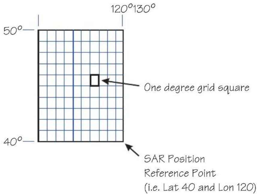
text_image
120°130° 50° One degree grid square 40° SAR Position Reference Point (i.e. Lat 40 and Lon 120)SAR POSITION LATITUDE : 40 LONGITUDE : 120
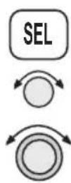
- Press SEL and use the SMALL and LARGE knobs to set the grid position. The LAT and LON smart keys activate selection of the Lat and Lon coordinates. Coordinates are selected in 10^ increments.

- Press ENTER.
Sectional Aeronautical Chart Grids
| Chart Ident North | Grid Limit | South Grid Limit | West Grid Limit | East Grid Limit | Total Grids | Grids/ Row | |
| Seattle | SEA | 49 00N | 44 30N | 125 00W | 117 00W | 576 | 32 |
| Great Falls | GTF | 49 00N | 44 30N | 117 00W | 109 00W | 576 | 32 |
| Billings | BIL | 49 00N | 44 30N | 109°00W | 101 00W | 576 | 32 |
| Twin Cities | MSP | 49 00N | 44 30N | 101 00W | 93 00W | 576 | 32 |
| Green Bay | GRB | 48°15N | 44 00N | 93 00W | 85 00W | 544 | 32 |
| Lake Huron | LHN | 48 00N | 44 00N | 85 00W | 77 00W | 512 | 32 |
| Montreal | MON | 48 00N | 44 00N | 77 00W | 69 00W | 512 | 32 |
| Halifax | HFX | 48 00N | 44 00N | 69 00W | 61 00W | 512 | 32 |
| Klamath Falls | LMT | 44 30N | 40 00N | 125 00W | 117 00W | 576 | 32 |
| Salt Lake City | SLC | 44 30N | 40°00N | 117 00W | 109 00W | 576 | 32 |
| Cheyenne | CYS | 44 30N | 40 00N | 109 00W | 101 00W | 576 | 32 |
| Omaha | OMA | 44 30N | 40 00N | 101 00W | 93 00W | 576 | 32 |
| Chicago | ORD | 44 00N | 40 00N | 93 00W | 85 00W | 512 | 32 |
| Detroit | DET | 44 00N | 40 00N | 85 00W | 77 00W | 512 | 32 |
| New York | NYC | 44 00N | 40°00N | 77 00W | 69 00W | 512 | 32 |
| San Francisco | SFO | 40 00N | 36 00N | 125 00W | 118 00W | 448 | 28 |
| Las Vegas | LAS | 40 00N | 35 45N | 118 00W | 111 00W | 476 | 28 |
| Denver | DEN | 40 00N | 35 45N | 111 00W | 104 00W | 476 | 28 |
| Wichita | ICT | 40 00N | 36 00N | 104 00W | 97 00W | 448 | 28 |
| Kansas City | MKC | 40 00N | 36 00N | 97 00W | 90 00W | 448 | 28 |
| St. Louis | STL | 40 00N | 36 00N | 91 00W | 84 00W | 448 | 28 |
| Cincinnati | LUK | 40 00N | 36 00N | 85 00W | 78 00W | 448 | 28 |
| Washington | DCA | 40 00N | 36 00N | 79 00W | 72 00W | 448 | 28 |
| Los Angeles | LAX | 36 00N | 32 00N | 121 30W | 115 00W | 416 | 26 |
| Phoenix | PHX | 35 45N | 31 15N | 116 00W | 109 00W | 504 | 28 |
| Albuquerque | ABQ | 36 00N | 32 00N | 109 00W | 102 00W | 448 | 28 |
| Dallas-Ft. Worth | GSW | 36 00N | 32 00N | 102 00W | 95 00W | 448 | 28 |
| Memphis | MEM | 36 00N | 32 00N | 95 00W | 88 00W | 448 | 28 |
| Atlanta | ATL | 36 00N | 32 00N | 88 00W | 81 00W | 448 | 28 |
| Charlotte | CLT | 36 00N | 32 00N | 81 00W | 75 00W | 384 | 24 |
| El Paso | ELP | 36 00N | 28 00N | 109 00W | 103 00W | 384 | 24 |
| San Antonio | SAT | 32 00N | 28 00N | 103 00W | 97 00W | 384 | 24 |
| Houston | HOU | 32 00N | 28 00N | 97 00W | 91 00W | 384 | 24 |
| New Orleans | MSY | 32 00N | 28 00N | 91 00W | 85 00W | 384 | 24 |
| Jacksonville | JAX | 32 00N | 28 00N | 85 00W | 79 00W | 384 | 24 |
| Brownsville | BRO | 28 00N | 24 00N | 103 00W | 97 00W | 384 | 24 |
| Miami | MIA | 28 00N | 24 00N | 83 00W | 77 00W | 384 | 24 |
Selecting A Pattern
Three pattern types provide you with the ability to perform a search that best suits your needs. The three types include Parallel Line, Creeping Line, and Expanding Square.
PAT

ENTER
- While viewing the SAR Map page, press the PAT (Pattern) smart key.
- Turn the SMALL knob to select the desired pattern type. Press ENTER to choose the pattern and to start selecting the available options.
PANALL LINE
SEARCH PAGE
PRESS ENTER
ENTER
ENTER
- Select the desired options and press ENTER.
- Press ENTER to activate the search pattern. You will automatically return to the SAR Map page. The PAT annunciator above the smart key will be highlighted.
- Press PAT again to disable the search pattern. The PAT annunciator above the smart key will no longer be highlighted.
PAT
Parallel Line Search Pattern
The Parallel Line search pattern selection allows you to create a search pattern along parallel lines based on an established grid.
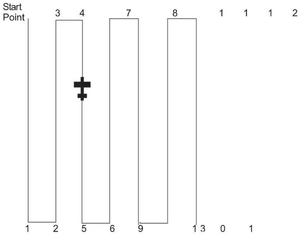
bar
| Start Point | Value | | :--- | :--- | | 1 | 0 | | 2 | 0 | | 3 | 3 | | 4 | 4 | | 5 | 5 | | 6 | 0 | | 7 | 7 | | 8 | 8 | | 9 | 0 | | 10 | 0 | | 11 | 0 | | 12 | 0 | | 13 | 0 | | 14 | 0 | | 15 | 0 | | 16 | 0 | | 17 | 0 | | 18 | 0 | | 19 | 0 | | 20 | 0 | | 21 | 0 | | 22 | 0 | | 23 | 0 | | 24 | 0 | | 25 | 0 | | 26 | 0 | | 27 | 0 | | 28 | 0 | | 29 | 0 | | 30 | 0 | | 31 | 0 | | 32 | 0 | | 33 | 0 | | 34 | 0 | | 35 | 0 | | 36 | 0 | | 37 | 0 | | 38 | 0 | | 39 | 0 | | 40 | 0 | | 41 | 0 | | 42 | 0 | | 43 | 0 | | 44 | 0 | | 45 | 0 | | 46 | 0 | | 47 | 0 | | 48 | 0 | | 49 | 0 | | 50 | 0 | | 51 | 0 | | 52 | 0 | | 53 | 0 | | 54 | 0 | | 55 | 0 | | 56 | 0 | | 57 | 0 | | 58 | 0 | | 59 | 0 | | 60 | 0 | | 61 | 0 | | 62 | 0 | | 63 | 0 | | 64 | 0 | | 65 | 0 | | 66 | 0 | | 67 | 0 | | 68 | 0 | | 69 | 0 | | 70 | 0 | | 71 | 0 | | 72 | 0 | | 73 | 0 | | 74 | 0 | | 75 | 0 | | 76 | 0 | | 77 | 0 | | 78 | 0 | | 79 | 0 | | 80 | 0 | | Note: The 'Start Point' is positioned at position (5) on the x-axis. The 'Value' in the 'Start Point' column is explicitly labeled as '3', which is the first value in the chart. The 'Value' in the 'Start Point' column is explicitly labeled as '4'. The 'Value' in the 'Start Point' column is explicitly labeled as '5'. The 'Value' in the 'Start Point' column is explicitly labeled as '6'. The 'Value' in the 'Start Point' column is explicitly labeled as '7'. The 'Value' in the 'Start Point' column is explicitly labeled as '8'. The 'Value' in the 'Start Point' column is explicitly labeled as '9'. The 'Value' in the 'Start Point' column is explicitly labeled as '10'. The 'Value' in the 'Start Point' column is explicitly labeled as '11'. The 'Value' in the 'Start Point' column is explicitly labeled as '12'. The 'Value' in the 'Start Point' column is explicitly labeled as '13'. The 'Value' in the 'Start Point' column is explicitly labeled as '14'. The 'Value' in the 'Start Point' column is explicitly labeled as '15'. The 'Value' in the 'Start Point' column is explicitly labeled as '16'. The 'Value' in the 'Start Point' column is explicitly labeled as '17'. The 'Value' in the 'Start Point' column is explicitly labeled as '18'. The 'Value' in the 'Start Point' column is explicitly labeled as '19'. The 'Value' in the 'Start Point' column is explicitly labeled as '20'. The 'Value' in the 'Start Point' column is explicitly labeled as '21'. The 'Value' in the 'Start Point' column is explicitly labeled as '22'. The 'Value' in the 'Start Point' column is explicitly labeled as '23'. The 'Value' in the 'Start Point' column is explicitly labeled as '24'. The 'Value' in the 'Start Point' column is explicitly labeled as '25'. The 'Value' in the 'Start Point' column is explicitly labeled as '26'. The 'Value' in the 'Start Point' column is explicitly labeled as '27'. The 'Value' in the 'Start Point' column is explicitly labeled as '28'. The 'Value' in the 'Start Point' column is explicitly labeled as '29'. The 'Value' in the 'Start Point' column is explicitly labeled as '30'. The 'Value' in the 'Start Point' column is explicitly labeled as '31'. The 'Value' in the 'Start Point' column is explicitly labeled as '32'. The 'Value' in the 'Start Point' column is explicitly labeled as '33'. The 'Value' in the 'Start Point' column is explicitly labeled as '34'. The 'Value' in the 'Start Point' column is explicitly labeled as '35'. The 'Value' in the 'Start Point' column is explicitly labeled as '36'. The 'Value' in the 'Start Point' column is explicitly labeled as '37'. The 'Value' in the 'Start Point' column is explicitly labeled as '38'. The 'Value' in the 'Start Point' column is explicitly labeled as '39'. The 'Value' in the 'Start Point' column is explicitly labeled as '40'. The other columns are not present in this image. There are no additional data series or labels beyond these values.- Select grid
- Set spacing
- Set direction
-
Activate pattern
-
While viewing the SAR Map page, press the PAT smart key.
- Turn the SMALL knob to select the Parallel Line pattern type, if necessary. Press ENTER.
- Press SEL to start editing the Grid selection. The first character will flash.
GRID (US): 453C1 SPACING: 0.5 DIRECTION: N/S
PAT

SEL
Moving Map Functions

- Use the LARGE and SMALL knobs to select the desired Grid.
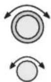
- Turn the LARGE knob to the Spacing option. Turn the SMALL knob to select the desired pattern spacing. You may select between 0.2 and 9.9 nm.

- Turn the LARGE knob to the Direction of Travel option. Turn the SMALL knob to select the desired Direction of Travel. You may select N/S or E/W.
ENTER
- Press ENTER when selections are complete.
ENTER
- Press ENTER to activate the search pattern. You will automatically return to the SAR Map page. The PAT annunciator above the smart key will be highlighted.
PAT
- Pressing the PAT smart key again will disable the pattern.
Creeping Line Search Pattern
The Creeping Line search pattern is similar to the Parallel Line Search. The starting point is any selected waypoint, rather than a designated grid based on aeronautical sectionals. The creeping line search pattern will straddle the center of your flight path. You may select the following options:
- Starting Waypoint
- Pattern spacing
• Direction of travel in 1 degree increments - Leg length
- Starting Side
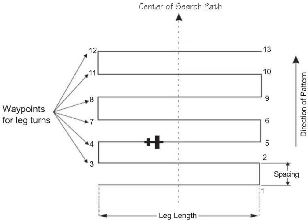
flowchart
graph TD
    A["Waypoints for leg turns"] --> B["12"]
    A --> C["11"]
    A --> D["8"]
    A --> E["7"]
    A --> F["4"]
    A --> G["3"]
    B --> H["13"]
    C --> I["10"]
    D --> J["9"]
    E --> K["6"]
    F --> L["5"]
    G --> M["2"]
    H --> N["Direction of Pattern"]
    I --> N
    J --> N
    K --> N
    L --> N
    M --> N
    N --> O["Spacing"]
    O --> P["1"]
    style O stroke-dasharray: 5 5
PAT
- While viewing the SAR Map page, press the PAT smart key.
- Turn the SMALL knob to select the Creeping Line pattern type, if necessary. Press ENTER.

ENTER
12.000000000000000000000000000000000000000000000000000000000000000000000000000000000000
SEARCH PAGE
- Press SEL. The Starting Waypoint field will flash "INS?" (insert) or "CHG?" (change). Press ENTER to start editing the Starting Waypoint selection.
START: INS? SPACING: 1.0 DIRECTION: 000+
ENTER

-
Choose a waypoint using normal selection methods. Then, press ENTER.
-
The Spacing option will flash. Turn the SMALL knob to select the desired pattern spacing. You may select between 0.2 and 9.9 nm.
START: PFC ARPT SPACING : 1.0 DIRECTION : 000+
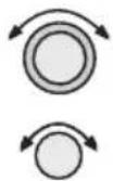
- Turn the LARGE knob to the Direction of Travel option. Turn the SMALL knob to select the desired Direction of Travel. You may select a direction from 0 to 359.
START: PFC ARPT SPACING : 1.5 DIRECTION : 000+
ENTER

-
Press ENTER when selections are complete.
-
Note the diamond on the lower, right portion of the screen. This indicates another available page. Turn the SMALL knob one position to view the next setup page.
SEL

- Select the Leg Length. Press SEL to start editing the Leg Length. Turn the SMALL knob to choose the Leg Length. You may select between 1.0 and 9.9 nm.
LEG LENGTH:5.0 START:RIGHT SIDE
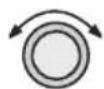
- Turn the LARGE knob to the Start Side selection. Turn the SMALL knob to choose Left or Right. This selection sets the side for the start of the search pattern.

flowchart
graph TD
    subgraph_Left_Side["Left Side"]
        A1["1"] --> B2["2"]
        B3["2"] --> C4["5"]
        C4 --> D5["6"]
        D5 --> E7["8"]
        E7 --> F9["10"]
        F9 --> G10["11"]
        G10 --> H12["12"]
        H12 --> I13["13"]
    end
    subgraph_Right_Side["Right Side"]
        J1["1"] --> K2["2"]
        K2 --> L3["5"]
        L3 --> M4["6"]
        M4 --> N5["8"]
        N5 --> O7["9"]
        O7 --> P8["10"]
        P8 --> Q9["11"]
        Q9 --> R10["12"]
    end
    Center_OCenter["Center of Search Path Center o"]
    style Center_OCenter fill:#f9f,stroke:#333
    style Right_Side fill:#ccf,stroke:#333
    note right of Center_OCenter: Center of Search Path Center o
    note right of Right_Side: f Search Path
LEG LENGTH:B:0 START:RIGHT SIDE
ENTER
- Press ENTER to accept the selected values.
LEG LENGTH: 8.0 START: LEFT SIDE
ENTER
- Press ENTER again to activate the search pattern. You will automatically return to the SAR Map page. The PAT annunciator above the smart key will be highlighted. Press the PAT smart key again to disable the search pattern.
PAT
Expanding Square Search Pattern
The Expanding Square search pattern is similar to the Creeping Line Search. Rather than parallel lines, an expanding square is radiated from the Starting Waypoint according to the spacing between lines and at an angle selected for the Direction of Travel. You may select the following options:
- Starting Waypoint
• Pattern spacing (0.2 to 9.9 nm)
• Direction of travel in 1 degree increments
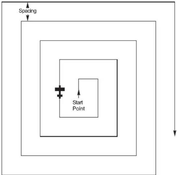
flowchart
graph TD
    A["Spacing"] --> B["Process Block"]
    B --> C["Start Point"]
    C --> D["End"]
PAT
- While viewing the SAR Map page, press the PAT smart key.
- Turn the SMALL knob to select the Expanding Square pattern type, if necessary. Press ENTER.
EXPANDING SQUARE SEARCH PAGE PRESS ENTER
SEL
ENTER
- Press SEL. The Starting Waypoint field will flash "INS?" (insert) or "CHG?" (change). Press ENTER to start editing the Starting Waypoint selection.
START: INS? SPACING :5.0 DIRECTION :000
ENTER
-
Choose a waypoint using normal selection methods. Then, press ENTER.
-
Turn the LARGE knob to the Spacing option. Turn the SMALL knob to select the desired pattern spacing. You may select between 0.2 and 9.9 nm.
START: ONP ARPT SPACING : 5.0 DIRECTION : 000

- Turn the LARGE knob to the Direction of Travel option. Turn the SMALL knob to select the desired Direction of Travel. You may select a direction from 0 to 359.
START: ONP ARPT SPACING : 3.5 DIRECTION : 000
ENTER
ENTER
PAT
-
Press ENTER when selections are complete.
-
Press ENTER again to activate the search pattern. You will automatically return to the SAR Map page. The PAT annunciator above the smart key will be highlighted. Press the PAT smart key again to disable the search pattern.
Mark A Position
When viewing the SAR Map page you may save a User waypoint to Mark a location of interest. Pressing the MRK (Marker) smart key saves a User waypoint at the present position of the aircraft when you save the waypoint.
MRK
-
While viewing the SAR Map page, press MRK.
-
The User waypoint creation page will appear with the current Lat/Lon position. The default waypoint name will be SAR000 (the first time). Subsequent User waypoints will automatically increment to SAR001, SAR002, etc.
SPROD2 USER
1.00 31 22 200000000 1.00 31 22 200000000 1.00 31 22 200000000 1.00 31 22 200000000 1.00 31 22 200000000 1.00 31 22 20008888888888888888888888888888888888888888888888888888888888888888888888 1.00 31 22 200000000 1.00 31 22 200000000 1.00 31 22 200000000 1.00 31 22 200000000 1.00 31 22 20079999999999999999999999999999999999999999999999999999999999999999999999999999999999999999999999999999
123° 30. (90)
SAR User Waypoints
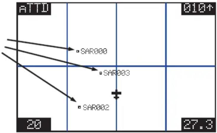
text_image
ATTO 010+ SAR000 SAR003 SAR002 20 27.3
ENTER
-
You may change the name and position with the LARGE and SMALL knobs.
-
Press ENTER to store the displayed name and position. The USER waypoint type symbol and ID must be turned on for the waypoint to show up on the map display.
Create A User Waypoint By US Grid
This feature allows you to set a US Grid coordinate, such as the corner of a grid, as a User waypoint so you can fly Direct-To the starting point in a grid for flying a search pattern. You must have selected the US Grid type on the SAR Setup page to have this display available.
- Press the DB smart key. Turn the LARGE knob to the "Create User Wpt By US Grid" page. Press ENTER.
CREATE USER HPT BY US GRID PRESS ENTER
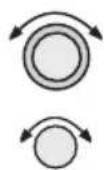
- The first character of the Grid will flash. Use the LARGE and SMALL knobs to select the desired Grid location.
1A1.....USER 49°00.00N 125°00.00H

- Press ENTER to save the displayed Grid location as a User waypoint.
Fly Direct To A US Grid
After creating a User waypoint for a US Grid, you can fly Direct-To, or set a flight plan to, the starting corner of that grid to begin a search pattern.

- Press DIRECT-TO. Turn the SMALL knob to choose the User waypoint type, if necessary.

- Use the LARGE and SMALL knobs to select the desired waypoint.

-
Press ENTER.
-
Navigate to the selected grid.
Create a User Waypoint By Basic Grid
This feature allows you to set a waypoint on the southeast corner Basic Grid coordinate as a User waypoint. You can then fly Direct-To the starting point in a grid for flying a search pattern. You must have selected the Basic Grid type on the SAR Setup page (see page 4-16) to have this display available.
The SAR Position (see page 4-18) is a reference point on the southeast corner of a 10^ by 10^ grid. Each one degree grid is then divided into 30' and 15' segments which are noted by alpha characters.
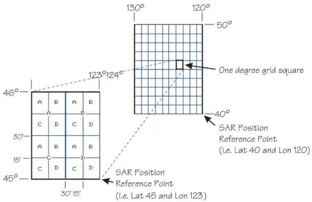
text_image
130° 120° 50° 123°124° One degree grid square 46° A B A B C D C D 30° A B A B 15° C D C D 45° 30' 15' 40° SAR Position Reference Point (i.e. Lat 40 and Lon 120) SAR Position Reference Point (i.e. Lat 45 and Lon 123)If you want to fly to the Bravo-Charlie 3 corner of the 45^ N and 123^ W grid, you would define the corner as a USER waypoint with the name “53BC3.” The SAR position is set to 40^ N and 120^ W.

text_image
123°124° 46° Basic Grid User Waypoint 53BC3 45° New SAR Position Reference Point (i.e. Lat 45 and Lon 123)The “5” comes from the 5^ added to 40^ N. The next number, “3”, comes from the 3^ added to 120^ W. The first letter, “B”, notes the 30’ grid divisions. The second letter, “C”, notes the 15’ grid division.
- Press the DB smart key. Turn the LARGE knob to the "Create User Wpt By Basic Grid" page. Press ENTER.
CREATE USER MPT BY BASIC GRID PRESS ENTER
- The first character of the Grid will flash. Use the LARGE and SMALL knobs to select the desired Grid location.
00A1...USER 40°00.00N 120°00.00W
- Press ENTER to save the displayed Grid location as a User waypoint.
530°C USER 44°30.00N 122°15.00W
Fly Direct To A Basic Grid
After creating a User waypoint for a Basic Grid, you can fly Direct-To, or set a flight plan to, the starting corner of that grid to begin a search pattern.
- Press DIRECT-TO. Turn the SMALL knob to choose the User waypoint type, if necessary.
- Use the LARGE and SMALL knobs to select the desired waypoint.
- Press ENTER.
- Navigate to the selected grid.
Setting Up A Search Pattern
The process for setting up your Apollo GX for a Search and Rescue operation include:
• Turn Route Line On (See page 4)
- Setup Search and Rescue Map Page (See page 4-16)
- Set Your Search and Rescue Position (Basic Grid only) (See page 4-18)
- Select and activate a Search Pattern (See page 4-20)
Waypoint Database
Waypoint Information
The Apollo GX provides an extensive built-in database of waypoint information to aid the navigator. Waypoints in the database are divided into 5 categories. This structure allows you to easily select a waypoint as a destination, search for waypoint information, search for nearest waypoints, or insert waypoints into a flight plan.
Turn LARGE Knob

Create WPT by Lat/Lon
Create WPT by Rad/Dist
Update User Wpt
Delete User Wpt
Modify User Wpt
Delete User Comment
Access Database
The waypoint types are:
• Airports (APTs)
• Very high frequency omniranges (VORs)
• Non-Directional Beacons (NDBs)
- Localizer-DME (LOC-DME)
• En route Intersections (INTs)
• User created (USERs)
Available Waypoint Information
The following information is available for each waypoint type. Use the waypoint INFO function to get this information as the Introduction describes in “Waypoint Information.”
AIRPORT Waypoint Information
• Identifier, city/facility name, state, & country
- Bearing and distance From/To present position
• Radio communication frequencies
• Airport type (public, etc.)
- Airport elevation
• Fuel availability by type
• Runway map, length(s), surface type, & lighting
• Approach info (GX50/60 only)
• Lat/Lon coordinates
- Sunrise/Sunset times
- Waypoint comment
VOR Waypoint Information
• Identifier, name, state, & country
• Radial and distance from the VOR
• Bearing and distance from present position
- Map
- Operating frequency
• Lat/Lon coordinates
- Sunrise/Sunset time
- Waypoint comment
NDB Waypoint Information
• Identifier, name, state, & country
• Bearing and distance from present position
- Map
- Operating frequency
• Lat/Lon coordinates
- Sunrise/Sunset time
- Waypoint comment
LOC-DME Waypoint Information
• Identifier, name, & country
• Bearing and distance from present position
- Map
• Lat/Lon coordinates
- Sunrise/sunset time
- Waypoint comment
INT Waypoint Information
• INT (K) - Continental USA Intersections
• INT (O) - Other Americas Intersections
- Name & country
• Bearing and distance from present position
- Map
- Lat/Lon coordinates
- Sunrise/sunset time
- Waypoint comment
USER Waypoint Information
• Name/Identifier (User entered)
• Lat/Lon coordinates (User entered)
• Runway Length (User entered)
• Bearing and distance from present position
- Map
- Sunrise/sunset time
- Waypoint comment
Getting Information About A Waypoint
You can access the Waypoint database by either looking directly or by using a feature that draws information from the database, such as using Emergency Search or creating a Flight plan. This section will describe going directly into the database, the other methods of using the waypoint database will be covered in the sections about the specific features. See “Select a Waypoint” in the Getting Started section on page 2-1 for more details on searching for waypoints.

- Press the DB key. Turn the LARGE knob to view the "Access Database" page, and then press ENTER.
AIRPORT AMF APALACHICOLA CITY FL USA

- The waypoint type field will flash. Choose Airport, VOR, NDB, Intersection, or User-defined with the SMALL knob.
AIRPORT AMF APALACHICOLA CITY FL USA
Waypoint Database
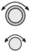
- Turn the LARGE knob to the first character of the waypoint name. The character will flash. Turn the SMALL knob to select the desired character.
AIRPORT PAE EVERETT CITY WA USA
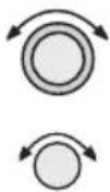
- Turn the LARGE knob clockwise one click to move to the next character. Turn the SMALL knob to select the desired character. Continue to select the needed characters.
PDX AIRPORT PORTLAND CITY OR USA
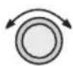
- You can also select the waypoint by the facility name. As you turn the LARGE knob to the city/facility field.
PDX AIRPORT PORTLAND CITY OR USA
Multiple (duplicate) facilities, identifiers, or cities with the same name will have a “dup” between the city/facility and state on the bottom row.
PDX AIRPORT PORTLAND CITY DUP OR USA
- Press SEL so the whole name flashes. Turn the SMALL knob to view the waypoints with the same city, facility name, or identifier.
TTD AIRPORT PORTLAND CITY DUP OR USA
INFO
- Press INFO to view information about the selected waypoint.
AIRPORT TTD PORTLAND-TROUTDA CITY DUP OR USA
ENTER
- Press ENTER or INFO to leave the function.
INFO
Airport Info Pages
The Apollo GX database holds the most needed information about each waypoint. The Airport information is described below. Similar information is available for each waypoint type. This information is shown after selecting the waypoint and pressing INFO.
Home Page
This is the page where the waypoint is selected from the Access Database page. The waypoint type, identifier, city/facility name, state/province, and country are shown. Use the SEL key and LARGE/SMALL knobs as described in Getting Information About A Waypoint on page 5-3.
FIRPORT SALE SALEM CITY OR USA
Title Page
This is the first page shown after pressing INFO. The identifier, waypoint type, facility name, state/province, and country are shown.
SLE AIRPORT MC NARY FACIL OR USA

Bearing & distance from present position
Turn the SMALL knob to show the Bearing and Distance from your present position. An arrow shows the Relative Bearing to the waypoint from your present position.
PPOS TO SLE BEARING 341°↓ DISTANCE 121NM

Airport frequencies
Turn the SMALL knob to view the available frequencies for the waypoint. In the GX60/65, the center three smart keys indicate the available frequencies. Press the smart key to load the indicated frequency into the Standby position.
SLE ATIS 124.55 UNIC 122.95 TWR 119.10

ILS Info
Turn the SMALL knob to view ILS runway information, when available. The waypoint identifier, ILS frequency, and runway are shown.
SLE ILS 110.30 RUNNAY 31

Identifier, type, & elevation
Turn the SMALL knob to view the airport type (public/private) and elevation.
SLE AIRPORT PUBLIC ELEV 210FT
Fuel Availability
Turn the SMALL knob to view fuel availability.

Turn the SMALL knob to view a map of the waypoint and location. If the waypoint is an airport, the runway map will be shown. You can change the map scale by pressing SEL and then turning the SMALL knob. Press SEL again to disable map scaling.
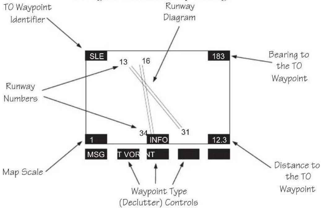
flowchart
graph TD
    A["TO Waypoint Identifier"] --> B["SLE"]
    C["Runway Numbers"] --> B
    D["Map Scale"] --> E["MSG"]
    D --> F["TVOR"]
    D --> G["NT"]
    H["Distance to the TO Waypoint"] --> I["12.3"]
    J["Waypoint Type (Declutter) Controls"] --> K["INFO"]
    L["Bearing to the TO Waypoint"] --> M["183"]
    N["13"] --> B
    O["16"] --> B
    P["34"] --> E
    Q["31"] --> G
    R["12.3"] --> I
Runway Info
Turn the SMALL knob to view runway information. For each runway, the length, type, and lighting are shown.

LENS
SHORT HARD JILS
LICHEN
Approach Info (GX50/60 only)
Turn the SMALL knob to view information about each approach.

text_image
M H F I SLE APPR NDB 31 NSL IAF NSL PAF RW31 MAP NSL MAHF SCALE 4NMLat/Lon Position
Turn the SMALL knob to view the Lat/Lon position.


SLE AIRPORT LAT 44°54.57N LON 123°00.15N

Sunrise/Sunset Time
Turn the SMALL knob to view the Sunset/Sunrise time for the waypoint in UTC time. You can change the day and month to view alternate times by pressing SEL and then using the SMALL and LARGE knobs. Press ENTER if desired to hold the date.
07 NOV UTC TIME SLE RISE15:05 ARPT SET 00:46

Waypoint Comment
Turn the SMALL knob to view the Waypoint Comment page. If there is no waypoint comment, press SEL to start creating a waypoint comment. If a comment has already been created, it will be displayed here. For further details, see Creating Waypoint Comments on page 5-14.
VISIT THE IT HORNOW FACTORY
Create User Waypoint by Lat/Lon
The Apollo GX allows you to create up to 500 of your own waypoints to the waypoint database. You can create a waypoint based on a Lat/Lon or using a radial and distance from another waypoint. The starting Lat/Lon coordinates are your present position You can also add the runway length. Unlike normal database waypoints a User waypoint with a runway of 0 length will appear in the nearest list and on the map if a length is set for the runway limit in the Nearest Search function, see page 3-12.
DB
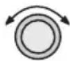
ENTER
- Press the DB soft key. Turn the LARGE knob to view the "Create User Wpt By Lat/Lon" page, and then press ENTER.
CREATE USER NPT BY LAT/LON PRESS ENT

- The first character of the waypoint name will flash. Turn the SMALL knob to select the desired character.
HAPP USER
10 42 43 44 45 46 47 48 49 50 51 52 53 54 55 56 57 58 59 60 61 62 63 64 65 66 67 68 69 70 71 72 73 74 75 76 77 78 79 80 81 82 83 84 85 86 87 88 89 90 91 92 93 94 95 96 97 98 99 100 10 42 43 44 45 46 47 48 49 50 51 52 53 54 55 56 57 58 59 60 61 62 63 64 65 66 67 68 69 70 71 72 73 100 10 42 43 44 45 46 47 48 49 50 51 52 53 54 55 10 42 10 10 10 10 10 10 10 10 10 10 10 10 10 10 10 10 10 10 10 10 10 10 10 10 10 10 10 10 10 10 10 10 10 10
10 201100 0000003 10 20110000 04 20110000 04 20110000 04 20110000 04 20110000 04 20110000 04 20110000 04 20110000 04 20110000 04 20
11 201100 0000003 11 2011000 04 20110000 04 20110000 04 20110000 04 20110000 04 20110000 04 2011000
12 201155 888888888888888888888888888888888888888888888888888888888888888888888888888
13 201155 8888888888888888888888888888888888888888888
14 201155 999999999999999999999999999999999999999999999999999
15 201155 9999999999999999999999999999999999999999
16 201155 777777777777777777777777777777777777777777777777
17 201155 666666666666666666666666666666666666666666666666666666666666
18 201155 53333333333333333333333333333333333333333333
19 201155 4222222222222222222222222222222222
20 201155 42222222222222222222222222
21 201155 42222222222222222222222
22 201155 422222222222222222222
23 201155 42222222
- Turn the LARGE knob clockwise one click to move to the next character. Turn the SMALL knob to select the desired character. Continue to select the needed characters for the Waypoint Name, Latitude, Longitude, and Runway Length.
01 00 01 02 03 04 05 06 07 08 09 10 11 12 13 14 15 16 17 18 19 20 21 22 23 24 25 26 27 28 29 30 31 32 33 34 35 36 37 38 39 40 41 42 43 44 45 46 47 48 49 50 51 52 53 54 55 56 57 58 59 60 61 62 63 64 65 66 67 68 69 70 71 72 73 74 75 76 77 78 79 80 81 82 83 84 85 86 87 88 89 90 91 92 93 94 95 96 97 98 99 100 01.00.01.02.03.04.05.06.07.08.09.10.11.12.13.14.15.16.17.18.19.20.21.22.23.24.25.26.27.28.29.30.31.32.33.34.35.36.37.38.39.40.41.42.43.44.45.46.47.48.49.50.51.52.53.54.55.56.57.58.59.60.61.62.63.64.65.66.67.68.69.70.71.72.73.74.75.76.77.78.79.80.81.82.83.84.85.86.87.88.89.90.91.92.93.94.95.96.97.98.99.100
441°224.229N RMLLEN
122°51.524 00009'
Note

The default Lat/Lon is your present position. This makes it easy to “mark” a location.
Waypoint Database
ENTER
- Press ENTER when you have finished entering the waypoint information.
HOME USER 44°24.29N RWLEN 122°51.52W 3000'
Create User Waypoint by Radial/Distance
A User waypoint may also be created where its position is referenced by a Radial and Distance from another waypoint.
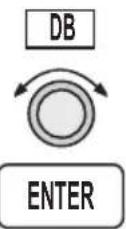
- Press the DB soft key. Turn the LARGE knob to view the "Create User Wpt By Rad/Dis" page, and then press ENTER.
CREATE USER WPT BY RADIAL/DIST PRESS ENT
- The first character of the radial will flash.
REF WPT: AAF 000.0° 000.0NM

- Select the Reference Waypoint. Turn the LARGE knob ccw one click to select the waypoint identifier which will be replaced by the change prompt (Chg?). Press ENTER to change the waypoint identifier.
REF HPT: CHC? 000.0° 000.0NM

- Turn the SMALL knob to select the desired waypoint type. Only Airports, NDBs, and VORs may be used as reference points. Turn the LARGE knob clockwise one click to move to the first character of the identifier. Turn the SMALL knob to select the desired character. Use the LARGE and

SMALL knobs to choose the identifier. After the reference waypoint name is chosen, press ENTER.

text_image
REF HPT: SLE 000.0° 000.0NM
- The first character of the radial will flash. Now select the needed characters for the Radial and Distance. Turn the SMALL knob to change characters. Turn the LARGE knob to move to the next character.
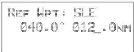
text_image
REF WPT: SLE 040.0° 012.0NM- Press ENTER when you have finished entering the waypoint information. You will be prompted to create a name for the waypoint.


text_image
#000 USER 44°10.96N RMLLEN 121°43.35H 0000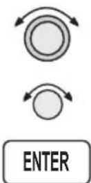
- Now, use the LARGE and SMALL knobs to enter the waypoint name. You can also adjust Lat/Lon and add the Runway Length. Changing the Lat/Lon will alter the radial/distance value, so you shouldn't change it unless you need to. Press ENTER when you are finished.

text_image
CABIN USER 44°10.96N RWLEN 121°43.35W 0000"Update User Wpt with Present Pos
Update the Lat/Lon coordinates of an existing User waypoint to your present position. You may also change the name and other info for the waypoint.
DB

ENTER
-
Press the DB key.
-
Turn the LARGE knob to view the "Update User Waypoint" page. Press ENTER.
UPDATE USER HPT WITH PPOS PRESS ENT

ENTER
- The waypoint identifier will flash. Turn the SMALL knob to choose the User waypoint you want to change. Press ENTER.
FIND WPT TO SET AA USER PRESS ENTER
ENTER
- The User waypoint information is displayed next. Press ENTER to accept the displayed information or use the LARGE and SMALL knobs to edit the information.
Delete User Waypoint
Remove a User waypoint from the database.
DB
- Press the DB key.
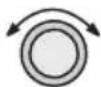
- Turn the LARGE knob to view the "Delete User Waypoint" page.
DELETE USER HPT PRESS ENT
ENTER
- Press ENTER. The waypoint identifier will flash. Turn the SMALL knob to view the User waypoints.

FIND HPT TO DEL CABIN USER Press ENT
ENTER
- When the waypoint to delete is displayed, press ENTER.
Modify User Waypoint
DB

ENTER
- Press the DB key. Turn the LARGE knob to view the "Modify User Wpt" page, and then press ENTER.
MODIFY USER HPT PRESS ENT
- Turn the SMALL knob to view the User waypoints.

FIND UPT TO MOD CABIN USER PRESS ENT
- When the waypoint to modify is displayed, press ENTER. The first character of the waypoint identifier will flash.
ENTER
CABIN USER 44°10.96N RULEN 121°43.35N 0000'

- Turn the SMALL knob to select the desired character. Turn the LARGE knob clockwise one click to move to the next character.
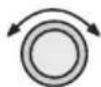
HABIN USER 44°10.96N RWLEN 121°43.35N 0000"
Waypoint Database

ENTER
- Turn the SMALL knob to select the desired character. Continue using the SMALL knob to change characters and the LARGE knob to move to the desired character. After the correct characters are chosen, press ENTER.
Creating Waypoint Comments
You may add comments to up to 200 waypoints. The comments are added while viewing the Info for any waypoint.
INFO
- While viewing the desired waypoint, press INFO. Turn the SMALL knob to the Waypoint Comment page and press SEL.

SEL
WAYPOINT COMMENT
P. P. P. P. P.
- The first character flashes on a blank screen. You can add 16 characters per line for three lines. Upper case letters, numbers, and spaces are allowed.
-


ENTER
- Turn the LARGE and SMALL knobs to edit the comment. Press ENTER to save the comment.
900FT TOWER 14NHL
NLI OF AIRPORT
STHY EAST OF TUR
Deleting Waypoint Comments
You may delete any of the waypoint comments that you have created.
DB

- Press DB and then turn the LARGE knob to the "Delete Waypoint Comment" page.
DELETE WAYPOINT COMMENT: 5 USED PRESS ENT
ENTER
- Press ENTER to view the waypoint comments. The first waypoint comment page will show the waypoint identifier, waypoint type, and a portion of the comment. The waypoint identifier will flash.
ORBIN USER 900FT TONER 14NN NW OF AIRPORT

- Turn the SMALL knob to view the available waypoint comments. Press ENTER to delete the displayed comment.
ENTER
Update User Waypoint
The Update User Waypoint function allows you to change the position of an existing User waypoint to your present position.
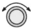
ENTER
- In the Database function, turn the LARGE knob to "Update User Wpt With Ppos." Then, press ENTER.
UPDATE USERT HPT WITH PPOS PRESS ENTER

ENTER
- A list of the User waypoints is available. The User waypoint ID will flash. Turn the SMALL knob to display the desired waypoint and then press ENTER.
FIND WPT TO SET HOOO USER PRESS ENTER
Datacard
The datacard contains all of the waypoint information except what is added by the user. The information contained in the datacard is updated on a regular basis. Contact the factory for obtaining new datacards for the appropriate coverage and time period. C129 operations require using the latest information.
Remove the datacard by pressing the ejector button located to the right of the datacard. Insert the datacard by pushing it completely into the slot. Follow the directions on the card for proper orientation.
RNAV Waypoints
Intersections associated with RNAV approaches can be found by loading the approach in which they occur. They may not be contained in the “INT (K)” files of the database. Should you be required to navigate to one of these intersections, you must first load the associated approach and then initiate a “Direct To” to that waypoint in Flight Plan mode.
Flight Plan Functions
Flight plans are specific routes between waypoints you may store in the Apollo GX memory. This information is used to calculate useful flight statistics. The Flight Plan function allows you to have up to 30 stored flight plans. Each flight plan may have up to 20 legs. The Active flight plan is always used for the current flight. Inactive flight plans may be activated in the Flight Plan function and copied to the Active flight plan.
Flight Plan Leg pages show the leg number and FROM and TO waypoint identifiers on the display, along with the bearing and distance between the FROM and TO waypoints. One asterisk (*) next to the leg number means that the displayed leg is in the Active flight plan. Two asterisks (**) mean that the displayed leg is the active leg and shows the current FROM and TO waypoints which are being used for navigation.
Turn LARGE Knob

Active
Flight
Plan
Flight Plan Pages
Flight
Plan
1

Flight
Plan
30
Create New
Flight Plan
The first page of each flight plan is the Name Page. The Name Page displays the flight plan name, total distance, and the destination waypoint. Distance is displayed as 0.0 to 99.9 nm at 0.1 nm resolution and 100 to 99999 nm at 1 nm resolution. A diamond ✦ at the right side of the display indicates that more pages can be viewed by turning the SMALL knob.
FPL
FPL

Reaching the Flight Plan Function
- Press FPL to reach the Flight Plan function. You may need to press NAV first if you were viewing the moving map. Press FPL twice to reach the flight plan home page. Turn the LARGE knob to view the
Flight Plan Functions
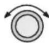
FPL
Flight Plan pages. The active leg is the default page you will see when pressing FPL once.
ACTIVE: 259MM
DEST HPT: PDT
Active 1

- Turn the SMALL knob to view the individual legs of a flight plan. Two asterisks indicate the active leg.
FLA: 100%
136 353° 48.0NM
姓名:____
性别:____
年龄:____
地址:____
电话:____
邮箱:____
紧急联系人:____
紧急联系电话:____
紧急联系人:____
紧急联系电话:____
紧急联系电话:____
紧急联系电话:____
紧急联系电话:____
紧急联系电话:____
紧急联系电话:____
紧急联系电话:____
紧急联系电话:____
紧急联系电话:____
紧急联系电话:____
紧急联系电话:____
紧急联系电话:____
紧急联系电话:____
紧急联系电话:____
紧急联系电话:____
紧急联系电话:____
紧急联系电话:____
紧急联系电话:____
紧急联系电话:____
紧急联系电话:____
紧急电话:____
紧急电话:____
紧急电话:____
紧急电话:____
紧急电话:____
紧急电话:____
紧急电话:____
紧急电话:____
紧急电话:____
紧急电话:____
紧急电话:____
紧急电话:____
Active Flight Plan
The first plan in the Flight Plan function is the Active plan and is noted by the name *Active* with asterisks. This name cannot be changed in the Active page.
HAPPETIVES 250MM
DEST UP: PDT
H. H. H.
Creating a Flight Plan
The basic steps for creating a flight plan include: entering the plan name and inserting waypoints. You may then view flight plan information, activate the plan, and use the other options.
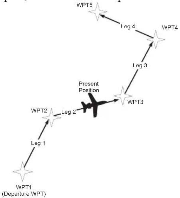
flowchart
graph TD
    WPT1["Departure WPT"] --> Leg1["Leg 1"]
    Leg1 --> WPT2["Leg 2"]
    WPT2 --> Leg2["Leg 2"]
    Leg2 --> PresentPosition["Present Position"]
    WPT3["WPT3"] --> Leg3["Leg 3"]
    Leg3 --> WPT4["WPT4"]
    WPT4 --> Leg4["Leg 4"]
    WPT5["WPT5"] --> Leg4
FPL

- Press the FPL key. Turn the LARGE knob to view the "Create a New Flightplan" page.
P. 2017
CREATE A NEW
FLIGHT PLAN
SEL

- Press SEL. The first character will flash. Turn the SMALL knob to select the first flight plan name character.
E
ENTER A NEW
- Turn the LARGE knob clockwise one click to move to the next character position. Turn the SMALL knob to select the next name character. You can have up to eight characters in the flight plan name.

ROUTE 2
- Press ENTER when the name is complete. A message will display telling you to turn the SMALL knob to insert waypoints or to press SEL for options. Options can be selected later.
SEL
TURN SMALL KNOB
TO INS HPTS OR
- After turning the SMALL knob, the first flight plan waypoint is ready for a FROM waypoint to insert.
1230000000000000000000000000000000000000000000000000000000000000000
- Press QL
To Edit Leg
Flight Plan Functions
SEL
ENTER
- Press SEL to insert a FROM waypoint. The Ins? prompt will flash. Press ENTER to insert a FROM waypoint.
INS? TO 1. O. NM

- Turn the SMALL knob to select the waypoint type. Turn the LARGE knob to the waypoint identifier. Turn the SMALL knob to select the first character of the waypoint identifier.
AIRPORT EAA EAGLE CITY AK USA
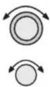
- Turn the LARGE knob clockwise one click to move to the next character position. Turn the SMALL knob to select the next name character.
AIRPORT EUG EUGENE CITY OR USA
ENTER
ENTER
- After selecting the waypoint name, press ENTER. The Ins? prompt will flash in the TO waypoint position. Press ENTER again to start the waypoint retriever.
EUG TO INS? 1. 0. NM
- Repeat steps 7-10 for the remaining waypoints in your flight plan.
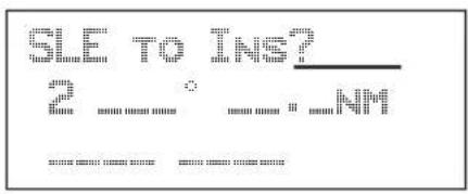
text_image
GLE TO INS? 2 : "NM"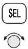
- Press SEL when your flight plan is complete. Turn the SMALL knob to view the legs in your flight plan.
Press SEL while viewing a flight plan leg page to make changes.
Press SEL and then turn the SMALL knob while viewing the flight plan name page to activate or to choose other options. See the Flight Plan Options description on page 6-14.
Flight Plan Sequencing
The Apollo GX will automatically sequence from one leg to the next as you fly past each waypoint. A line that evenly divides (bisects) the angle between the two legs determines when the flight plan sequences to the next leg.
In the example below, the dashed line describes the area where the flight plan will sequence from Leg 1 to Leg 2 and for the last waypoint (Wpt 3).
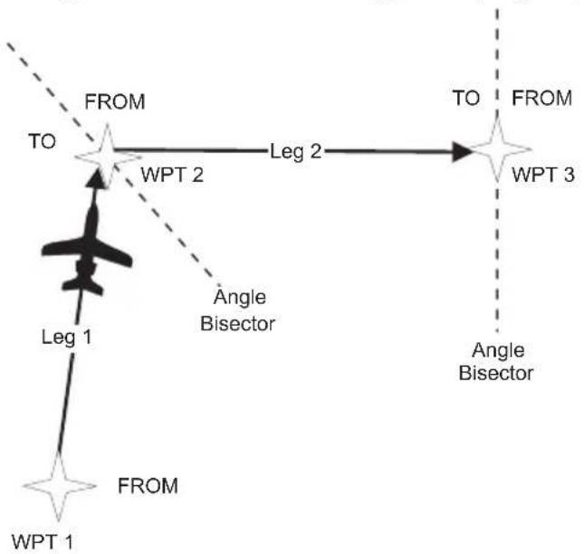
flowchart
graph TD
    A["WPT 1"] -->|Leg 1| B["To"]
    B -->|From| C["WPT 2"]
    C -->|Leg 2| D["To"]
    D -->|From| E["WPT 3"]
    E -->|Angle Bisector| D
    style A fill:#f9f,stroke:#333
    style B fill:#ccf,stroke:#333
    style C fill:#cfc,stroke:#333
    style D fill:#fcc,stroke:#333
    style E fill:#cff,stroke:#333
Flight Plan Leg Information
Two types of information are available within flight plan legs: waypoint and flight information. Pressing INFO will provide information about the destination waypoint. Information about the ETA, ETE, Ground Speed, and Fuel is also available for each leg by selecting which option you like to view in the leg display.
SEL
- While viewing a flight plan leg, press SEL. The From waypoint field will flash.
CHG? TO SLE 1 353° 48.0MM ARPT ARPT

- Turn the LARGE knob clockwise two clicks to choose the third line for selection. The line will flash.
EUG TO SLE 1 353° 48.0MM ARPT ARPT

- Turn the SMALL knob to choose from the list of available leg information options. The options are described on the following pages.
EUG TO SLE 1 353° 48.0NM LEG ETE 00:30
ENTER
- Press ENTER to keep your choice displayed or press SEL to cancel viewing and return to the Bearing and Distance information.
SEL
ETA
Estimated Time of Arrival is for the displayed TO waypoint and requires an actual ground speed of more than 5 knots. If there is no valid ETA for the leg, dashes will replace the value.
BUG TO SLE
1 353° 48.0MM
ETH 17:36
ETA?
ETA? is the same as ETA, except the Estimated Ground Speed is used for the calculation.
EUG TO SLE
1 353° 49.0MM
ETAP? 17:27
Leg ETE
The Estimated Time En Route between the displayed FROM and TO waypoints. Leg ETE requires an actual ground speed of more than 5 knots. If there is no valid ETA for the leg, dashes will replace the value.
EUG TO SLE
1 353° 48.0MM
LEG ETE 20:27
Leg ETE?
Leg ETE? is the same as ETE, except that Estimated Ground Speed is used for the calculation. See Estimated Ground Speed on page 6-16 for more details.
EUG TO SLE
1 353° 49.0NM
LEG ETE? 00:27
ETE
Estimated Time En route in the Active flight plan is from your present position. In an inactive flight plan, ETE uses the FROM waypoint. ETE requires an actual ground speed of more than 5 knots. If there is
no valid ETE for the leg, dashes will replace the value.
EUG TO SUE I SATE: 48.00 PM EFE 100"27
ETE?
ETE? is the same as ETE, except the Estimated Ground Speed is used for the calculation. See Estimated Ground Speed on page 6-16 for more details.
EUG TO SLE 1 353° 48.0NM LEG ETE? 00:24
Fuel To?
Fuel shows the amount of fuel required to get from the FROM waypoint to the TO waypoint for an inactive plan or from the present position to the TO waypoint for the Active flight plan. See Estimated Ground Speed on page 6-16 for more details.
EUG TO SALE 1 350° 48.0NM FUEL TO? 32USC
In the Active flight plan, the Fuel? Calculation uses the Estimated Fuel Usage value and the actual ground speed. The Estimated Fuel Usage value must be greater than zero, and the actual ground speed must be greater than 5 knots. If there is no valid Fuel? for the leg, dashes will replace the value.
In an inactive flight plan, the Fuel? calculation uses the Estimated Fuel Usage value and the estimated ground speed. The Estimated Fuel Usage value must be greater than zero, and the actual ground speed must be greater than 5 knots. If there is no valid Fuel? for the leg, dashes will replace the value.
Direct-To
If the leg page displayed is the currently active leg of the Active flight plan, and a Direct-To waypoint has been entered, the From waypoint will say “Direct.” The leg just prior to the currently active leg displays the leg as if the “Direct” waypoint did not exist. After sequencing, the “Direct” disappears, and the currently active leg once again displays the waypoint identifier. See page 3-31 for more details on using the Direct-To function.
DIRECT TO HPT4 23×026°125NM ARPT

flowchart
graph TD
    WPT1["Departure WPT"] --> Leg1["Leg 1"]
    WPT2["WPT2"] --> Leg2["Leg 2"]
    WPT3["WPT3"] --> Leg3["Leg 3"]
    Leg2 -.->|Present Position| WPT2
    Leg3 -.->|Direct-To Route| WPT4["WPT4"]
    Leg4 --> Leg5["WPT5"]
Manual Leg Activation
ENTER
ENTER
While viewing a leg page of the Active flight plan, pressing ENTER will provide the option for making the displayed leg the active leg. Press ENTER to activate the leg. Follow your CDI to intercept Leg 3. You cannot manually select a DME-Arc as a flight plan leg.
SLE TO MMV PRESS ENTER TO ACTIVATE LEG
Flight Plan Functions

flowchart
graph TD
    WPT1["Departure WPT"] --> Leg1["Leg 1"]
    WPT2["WPT2"] --> Leg2["Leg 2"]
    Leg2 --> SLE["SLE"]
    Leg2 --> WPT2
    Leg3["Leg 3"] --> MMV["MMV"]
    MMV --> Leg4["Leg 4"]
    Leg4 --> WPT5["WPT5"]
    WPT5 --> CDI["CDI"]
    style WPT1 fill:#f9f,stroke:#333
    style WPT2 fill:#f9f,stroke:#333
    style WPT5 fill:#f9f,stroke:#333
    style SLE fill:#fff,stroke:#000
    style MMV fill:#fff,stroke:#000
    style WPT5 fill:#fff,stroke:#000
Flight Plan Editing
You can alter any of the information you entered into the flight plans. The editing options include: Chg?, Ins?, and Del?
- Chg? - An existing waypoint can be changed if at least one valid waypoint exists in the database.
- Ins? - A waypoint can be inserted before an existing waypoint if at least one valid waypoint exists in the database. Inserting a new waypoint into the Active flight plan before or after the current TO waypoint does not affect the currently active leg. Inserting a new waypoint into the active leg's TO waypoint will immediately change navigation to the new TO waypoint.
- Del? - An existing waypoint can be deleted if it is not one of only two waypoints in the Active flight plan, except if the From waypoint is indicated as "Direct," which can always be deleted. When the "Direct" indicator is deleted, the waypoint that was overwritten by "Direct" will return as the original FROM waypoint. If you delete the current TO waypoint, the NEXT waypoint, if available, becomes the current TO waypoint. If the last TO waypoint is deleted, the previous From waypoint becomes the current To waypoint and the active leg number will be reduced (i.e. from leg 7 to leg 6).
Changing Existing Flight Plan Legs
- In the Flight Plan function, turn the LARGE knob to a flight plan and then use the SMALL knob to display the leg of the plan that you want to edit.

HIO TO TTD 3 070° 23.0NM ARPT ARPT

- Press SEL. The FROM waypoint will flash with the Chg? prompt. Turn the LARGE knob to the desired waypoint.
HIO TO CHG? 3 070° 23.0NM ARPT ARPT
ENTER
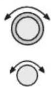
- Press ENTER. This takes you into the waypoint database. Use the LARGE and SMALL knobs to select the desired waypoint and then press ENTER.
AIRPORT DLS THE DALLES CITY OR USA
ENTER
HIO TO DLS 3 067° 75. ONM ARPT ARPT
Inserting a New Waypoint
- In the Flight Plan function, display the leg of the plan that you want to edit.
HTO TO DLS 3 067° 75. QNM ARPT ARPT
Flight Plan Functions

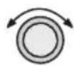
- Press SEL. The From waypoint will flash with the Ins? prompt. Turn the LARGE knob, if necessary, to the waypoint you want changed.

text_image
HIQ TO CHG? 3 067° 75.0NM ARPT ARPT
- If another option was last used, turn the SMALL knob to choose Ins?.
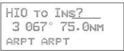
text_image
HIO TO INS? 3 067° 75.0NM ARPT ARPT
- Press ENTER. Use the LARGE and SMALL knobs to select the desired waypoint.


text_image
AIRPORT TTD PORTLAND CITY OR USA
- After selecting the waypoint name, press ENTER.

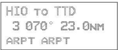
text_image
HI0 TO TTD 3 070° 23.0NM ARPT ARPTDeleting a Waypoint
- In the Flight Plan function, display the leg of the plan that you want to edit.

text_image
HIO TO TTD 3 070° 23.0NM ARPT ARPT
- Press SEL. The From waypoint will flash with the Chg? prompt. Turn the LARGE knob to the waypoint you want changed.

text_image
HIO TO CHG? 3 070° 23.0NM ARPT ARPT
- Turn the SMALL knob to choose Del?
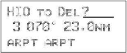
text_image
HIO TO DEL? 3 070° 23.0NM ARPT ARPT
- Press ENTER. The waypoint will be deleted. Each flight plan leg will shift back to replace the deleted leg, i.e. after deleting leg 3, leg 4 will then become leg 3.
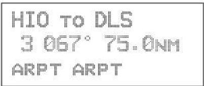
text_image
HIO TO DLS 3 067° 75.0NM ARPT ARPTBefore Deleting Leg
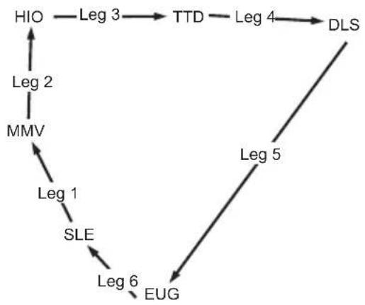
flowchart
graph TD
    HIO --> Leg3
    Leg3 --> TTD
    TTD --> Leg4
    Leg4 --> DLS
    Leg2 --> MMV
    MMV --> Leg1
    Leg1 --> SLE
    Leg6 --> EUG
    Leg5 --> Leg6
After Deleting Leg
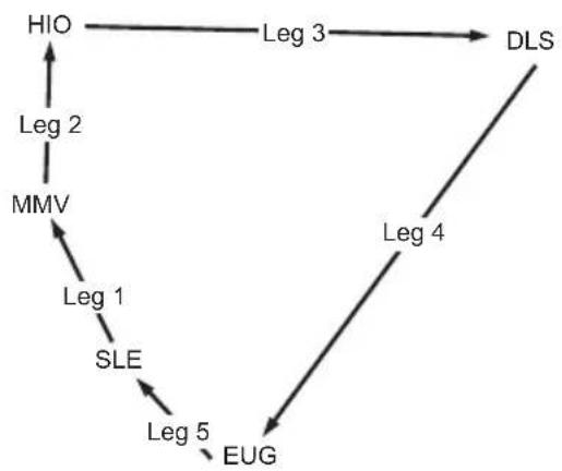
flowchart
graph TD
    HIO --> Leg2
    Leg2 --> MMV
    MMV --> Leg1
    Leg1 --> SLE
    SLE --> Leg5
    Leg5 --> EUG
    Leg3 --> DLS
    Leg4 --> DLS
Flight Plan Options

flowchart
graph TD
    A["Circle with Arrows"] --> B["Circle with Arrows"]
    B --> C["SEL"]
ENTER
In the Flight Plan function you may make changes to a flight plan.
- In the Flight Plan function turn the LARGE knob to a flight plan name page.
- Press SEL and then turn the SMALL knob to view the available functions.
- Press ENTER to activate the option.
Activate
Pressing ENTER when the “Activate” option is displayed copies the selected inactive flight plan to the active plan and activates the plan starting at Leg 1. If you have gone past a given leg, the next appropriate leg will be activated. In the Flight Plan function, turn the LARGE knob to view the available flight plans. Only Inactive plans may be Activated.
ROUTE 2 259NM DEST: HPT: PDT ACTIVATE?
When you Activate a flight plan, the Inactive flight plan is “copied” to the Active plan. Any changes made to the Active plan will have no effect on the original Inactive plan.
If you have made any changes to the Active plan, you can save it by copying it into a newly created Inactive plan. See Saving an Active Flight Plan on page 6-24.
COPYING ROUTE 2 TO ✕ACTIVE ✕ PLAN
Rev Activate
Pressing ENTER when the “Rev Activate” option is displayed copies the selected flight plan to the active plan in reverse waypoint order and starts it at leg 1.
ROUTE 2 259NM DEST: HPT: PDT REV ACTIVATE?
Reactivate
Press ENTER when the “Reactivate” option is displayed to reset the active leg to leg 1 and allow waypoint sequencing. Only used for the Active plan.
ROUTE 2 259NM DEST: HPT: PDT REACTIVATE?
Rename
Pressing ENTER when the “Rename Plan” option is displayed lets you rename the flight plan. Duplicate names are not allowed. Only used for Inactive plans.
ROUTE 2 259NM DEST: WPT: PDT RENAME PLAN?
Copy Plan
Pressing ENTER when the “Copy Plan” option is displayed allows you to copy any existing plan into the current plan, overwriting all of the current plan’s waypoints. You may choose the active or any inactive flight plan.

- While viewing the desired flight plan, press SEL and then turn the SMALL knob to the "Copy Plan?" option. Press ENTER.

text_image
ROUTE: 2 259NM DEST: WPT: PDT COPY PLAN?
- Turn the SMALL knob to select the flight plan you want to copy the flight plan into. Press ENTER.

text_image
ROUTE 2 259NM COPY: ×PLAN 9× Copy PLANEstimated Ground Speed
While viewing a leg in an Active flight plan, press ENTER when the “Est Gr Speed” option is displayed. This allows you to enter an estimated ground speed value to be used in estimating some leg info options, such as estimated fuel flow, Leg ETE?, ETE?, or ETA?.

text_image
ROUTE 2 259NM DEST: WPT: PDT EST GR SPEED?The estimated ground speed can be entered from 000 to 999 knots.
Clear Waypoints
Pressing ENTER will delete all waypoints in the selected flight plan. The plan name will remain.
ROUTE 2 259NM DEST: WPT: PDT CLEAR WPTS?
Reverse Flight Plan
Pressing ENTER when the “Reverse” option is displayed reverses all the waypoints in the current flight plan. This option is available only on inactive flight plans with two or more waypoints.
ROUTE 2 259NM DEST: HPT: PDT REVERSE?
Estimated Fuel Flow
Pressing ENTER when the “Est Fuel Flow” option is displayed allows you to enter an estimated fuel usage value to be used in estimating one of the leg info options.
ROUTE 2 259NM DEST: HPT: PDT EST FUEL FLOW?
The estimated fuel flow can be selected from 0000 to 9999 units per hour. The units may be set in the System function (see page 7-6). Pressing ENTER saves the entered value if the value entered is less than or equal to 999 US gallons per hour, after any necessary conversions are performed. If the value is too large when ENTER is pressed, it is truncated to the largest possible value for the units selected.
After entering the Estimated Fuel Flow, a four second help screen indicates either “Fuel To Uses Actual Gr Speed” when the current flight plan is the active flight
plan or “Fuel To Uses Est Gr Speed” when the current flight plan is an inactive, stored flight plan.
Delete Plan
Pressing ENTER when the “Delete Plan” option is displayed deletes the current flight plan. The display returns to the previous flight plan’s name (or first) page. The *Active* flight plan cannot be deleted, in which case this option is not displayed.
ROUTE 2 259NM DEST: HPT: PDT DELETE PLAN?
Hold
The Hold option is available for the Active flight plan when the flight plan status is Active (waypoint sequencing allowed). This function is used while viewing the Name Page. Hold allows you to overfly the Active plan's current TO waypoint without sequencing. When sequencing is started again, normal operation continues. So, if your aircraft has gone past the waypoint, it will immediately sequence to the next leg in your flight plan. See Flight Plan Sequencing on page 6-5 for more details.
- In the Flight Plan function, turn the LARGE knob to display the Name Page.
ACTIVE: 259NM DEST: NPT: PDT ACTIVE
- Press SEL. The "Hold?" option will flash.
ACTIVEX: 259NM DEST: NPT: PDT HOLD?
SEL
ENTER
- Press ENTER to place the active flight plan on hold. Waypoint sequencing will be inhibited on the current leg. Pressing OBS/HLD will also work.
*ACTIVE: 259NM DEST: WPT: PDT HOLDING
Holding Patterns (GX50/60)
A holding pattern is operationally the same as a procedure turn except that you usually intend to make repeated crossings of the waypoint on a specific inbound course. For a holding pattern, like for the procedure turn, the steps will always be to:
- First, verify that sequencing is suspended, the OBS/HLD annunciator is lit, or suspend sequencing by pressing the OBS/HLD button.
- Second, after crossing the waypoint, establish the desired inbound course to the waypoint by pressing DIRECT-TO twice or pressing ENTER for the “Set OBS Course” message. Select the inbound course with the SMALL and LARGE knobs, then press ENTER.
- Enter the holding pattern by the most appropriate entry method. For example, Direct, Teardrop, or Parallel, just as you would enter that holding pattern at a VOR. Finally, when you are ready to exit the holding pattern, press OBS/HLD while still on the “TO” side of the waypoint to enable sequencing the next time you cross the waypoint.
While you are in a holding pattern, the CDI/HSI cross-track deviation display and the TO/FROM flag will behave almost exactly the way they would if you were holding at a VOR. The TO/FROM flag will display “TO” prior to reaching the waypoint. The TO/FROM flag will display “FROM” after crossing the waypoint. TO and FROM is determined by position relative to a line drawn perpendicular to the
Flight Plan Functions
selected inbound course and through the waypoint. The CDI will indicate “fly-left” if the aircraft is to the right of the desired track with reference to the selected inbound course. The CDI will indicate “fly-right” if the aircraft is to the left of the desired track with reference to the selected inbound course. As with traditional VOR navigation, these indications are always related to the aircraft position and not to the heading or direction of flight.

text_image
"TO" Waypoint 360 selected as the inbound course "FROM" Waypoint Perpendicular to 360 inbound courseWhen you are ready to depart the hold, you enable sequencing with the OBS/HLD button. If you are on the “TO” side of the waypoint, the flight plan will sequence the next time you cross the waypoint. If you are on the “FROM” side of the waypoint, the flight plan will sequence immediately. The following example shows holding at the Newburg VOR (UBG)
Flight Plan Functions
with 020^ inbound selected as the “OBS” course to UBG.

text_image
"TO" Side "FROM" Side HIO (NEXT) UBG (TO) O20° Perpendicular to O20° 3S2 (FROM) If sequencing is enabled on the "TO" side of a line perpendicular to the destination waypoint, the flightplan will sequence to the "NEXT" waypoint when you cross the line. If sequencing is enabled on the "FROM" side of a line perpendicular to the inbound course at the active destination waypoint, the flightplan will sequence immediately to the "NEXT" waypoint.Continue
The Continue option is available for the Active flight plan when the flight plan status is Holding (waypoint sequencing is not allowed). Pressing ENTER when this option is displayed restarts the Active flight plan and enables waypoint sequencing.

- In the Flight Plan function, turn the LARGE knob to display the Name Page.
*ACTIVE* 259NM DEST: UPT: PDT HOLDING †
SEL
- Press SEL. The "Continue?" option will flash.
ACTIVE: 259NM
DEST: WPT: PDT CONTINUE?
ENTER
- Press ENTER to continue the active flight plan. Waypoint sequencing will be enabled.
Load Approach (GX50/60 Only)
This option is available for the Active flight plan when a datacard with approach information is inserted into the GX50/60. Press ENTER to show the available approaches for the destination airport. Press SEL while in the Nav or Map functions to go directly to this option.
ACTIVE: 56.1MM
DEST HPT: PDF
LOAD APPROACH?
Change Approach (GX50/60 Only)
This option is available on the Flight Plan home page when an approach is already loaded. Press ENTER to select a new approach for the current destination airport.
- 30
- 31
- 32
- 33
- 34
- 35
- 36
- 37
- 38
- 39
- 40
- 41
- 42
- 43
- 44
- 45
- 46
- 47
- 48
- 49
- 50
- 51
- 52
- 53
- 54
- 55
- 56
- 57
- 58
- 59
- 60
- 61
- 62
- 63
- 64
- 65
- 66
- 67
- 68
- 69
- 70
- 71
- 72
- 73
- 74
- 75
- 76
- 77
- 78
- 79
- 80
- 81
- 82
- 83
- 84
- 85
- 86
- 87
- 88
- 89
- 90
- 91
- 92
- 93
- 94
- 95
- 96
- 97
- 98
- 99
- 100
DEST : IPT = FOX
Unload Approach (GX50/60 Only)
This option is available on the Flight Plan home page when an approach is already loaded. Press ENTER to unload the approach from the active flight plan. The approach waypoints will be replaced by the destination waypoint.
- 300
- 300
- 300
- 300
- 300
- 300
- 300
- 300
- 300
- 300
- 300
- 300
- 300 12.
DEST: HPT = FOS
08 04 08 05 08 06 08 07 08 08 08 09 08 10 08 11 08 12 08 13 08 14 08 15 08 16 08 17 08 18 08 19 08 20 08 21 08 22 08 23 08 24 08 25 08 26 08 27 08 28 08 29 08 30 08 31 08 32 08 33 08 34 08 35 08 36 08 37 08 38 08 39 08 40 08 41 08 42 08 43 08 44 08 45 08 46 08 47 08 48 08 49 08 50 08 51 08 52 08 53 08 54 08 55 08 56 08 57 08 58 08 59 08 60 08 61 08 62 08 63 08 64 08 65 08 66 08 67 08 68 08 69 08 70 08 71 08 72 08 73 08 74 08 75 08 76 08 77 08 78 08 79 08 80 08 81 08 82 08 83 08 84 08 85 08 86 08 87 08 88 08 89 08 90 08 91 08 92 08 93 08 94 08 95 08 96 08 97 08 98 08 99 1
Enable Approach (GX50/60 Only)
This option is available on the Flight Plan home page when an approach is already loaded, but not enabled, and you are within approximately 30 nm of the destination airport. Press ENTER to enable the approach.
*ACTIVE* 56.1NM
DEST NPT: PDX
ENABLE APPROACH?
Disable Approach (GX50/60 Only)
This option is available on the Flight Plan home page when an approach is already loaded and enabled. Press ENTER to cancel the Approach Transition flight mode and return the GX50/60 to Terminal flight mode.
ACTIVE: 56.1MM
DEST NPT: PDX
DISABLE APPR?
Destination Waypoint Information
Normal waypoint information about the destination waypoint can be viewed by pressing INFO when the Plan Name Page is displayed. This is the same as pressing INFO to view information about a TO waypoint, except that the Plan Comment page is available by turning the SMALL knob.
PDT AIRPORT
PUBLIC
ELEV 1493FT
Flight Plan Comments
A flight plan comment page can be viewed and edited for each flight plan by pressing INFO when the Plan Name Page is displayed and the turning the LARGE knob.
If no plan comment has been entered, press SEL to create one.
Flight Plan Functions


- While viewing the desired flight plan, press INFO. Turn the SMALL knob to reach the Comment page.

text_image
WAYPOINT COMMENT PRESS SEL

- Press SEL. Turn the SMALL knob to select the first character.

natural_image
Simple black-and-white line drawing of a rectangular frame with no text or symbols

- Turn the LARGE knob clockwise one click to move to the next character position. Turn the SMALL knob to select the next comment character.

text_image
GOOD RESTAURANTENTER
Saving an Active Flight Plan
- After selecting the waypoint comment, press ENTER.
If you have made any changes to the Active plan, you can save it by copying it into a newly created Inactive plan. First, create a new Inactive flight plan without waypoints. Next, select the Copy Plan option while viewing the Active plan. Then, Copy the Active plan into the new plan you created.
FPL
- Press FPL to reach the Flight Plan function. Turn the LARGE knob ccw one click to display the Flight Plan creation page.
PRESS SEL TO CREATE A NEW FLIGHT PLAN
SEL


ENTER
- Press SEL and then use the LARGE and SMALL knobs to enter a new plan name. After entering the name, press ENTER.
PLAN 9 ENTER A NEW PLAN NAME
ENTER

- Press ENTER a second time or turn the SMALL knob twice to return to the Inactive Flight Plan name page. Don't insert any waypoints.
- Press SEL and turn the SMALL knob to show the Copy Plan? option. The option will flash. Press ENTER.
PLAN 9.0.ONM DEST WPT: "" COPY PLAN?

ENTER
- Choose the Active flight plan from the list of flight plans with the SMALL knob. The flight plan name will flash. Press ENTER.
PLAN 9 0. ONM COPY: ¥ACTIVE COPY PLAN
- Your new flight plan now has the contents of the Active flight plan copied into it. Your Active flight plan is not affected.
PLAN 9 204NM DEST UPT: PDX INACTIVE
An old navigation method
-
While holding your watch horizontal, point the hour hand at the sun.
-
Halfway between the hour hand and 12:00 is south.
Don't always depend on this method, but it is kind of fun.
System Functions
Pressing the SYS key allows you to access the System functions. After pressing the SYS key, turn the LARGE knob to view the available functions: Navigation Info, System Info, Position Sensors, Misc Sensors, and Comm Info (GX60/65 only). Press ENTER when viewing the desired System function.

flowchart
graph TD
    A["Press. SYS"] --> B["Turn LARGE Knob"]
    B --> C[", then press ENTER"]
    C --> D["Navigation Info"]
    C --> E["System Info"]
    C --> F["GPS Sensor"]
    C --> G["Misc Sensors"]
    C --> H["Comm Info (GX60/65 Only)"]
Navigation Information
The Navigation Information function allows to make adjustments on the way information is shown in the Navigation function. The pages available include: Airspace Setup, Autonav Time, Nav Mode Display Programming, Magnetic Variation, Flight Timer Trigger, Direct-To Entry Option, and CDI Scaling.

flowchart
graph TD
    A["Turn LARGE Knob"] --> B["Autonav Time"]
    A --> C["Lat/Lon Units"]
    A --> D["Program Nav Pages"]
    A --> E["Mag Var Flight Trigger"]
    A --> F["Direct-To Entry"]
    A --> G["CDI Scaling"]
Autonav Time is the delay time that each Navigation page will be displayed before rotating to the next page. Time may be selected from one to nine seconds. Press ENTER in the Nav function to activate Autonav.
System Functions
SEL
- While viewing the Autonav Time page, press SEL.
AUTONAV TIME: 4 SECONDS/PAGE

- Turn the SMALL knob to select the delay time.
AUTONAV TIME: T SECONDS/PAGE
ENTER
- Press ENTER when finished.
NAV
- Press NAV. While viewing the Nav functions, Press ENTER to start Autonav scrolling. Press ENTER again to stop Autonav scrolling.
ENTER
Navigation Mode Programmable and Autonav Pages This function allows you to customize both the look of the programmable basic navigation pages and the selection of pages used in the Autonav function. All basic Nav pages are programmable except the first (home) page.
SYS
Customizing Navigation Pages
- Press the SYS key. Turn the LARGE knob to reach the Navigation Info page and then press ENTER.

- Turn the LARGE knob to reach "Nav Mode Display and Autonav Pages."
ENTER
NAV MODE DISPLAY PROGRAMMABLE AND AUTONAV PAGES †

- Turn the SMALL knob cw to view the second (first editable) Nav page.
ETE SLE 00:20 2.00 A DTK 353 48.0NM
SEL
- Press SEL to activate editing. The first Nav field will flash.
FTSE 00:29
2.00
DTK 353 48.0NM

- Turn the SMALL knob to select the desired Nav information to be displayed in that field.
GROUNDSP 100 KTS
2.000
DTK 353 48.0NN

- Turn the LARGE knob to move to the next field to edit. Turn the SMALL knob to select the Nav information.

GROUNDSP 100 KTS
- When you are finished selecting Nav page information, press ENTER. You will be prompted to decide if you want to include this page in the Autonav scrolling.
01 02 03 04 05 06 07 08 09 10 11 12 13 14 15 16 17 18 19 20 21 22 23 24 25 26 27 28 29 30 31 32 33 34 35 36 37 38 39 40 41 42 43 44 45 46 47 48 49 50 51 52 53 54 55 56 57 58 59 60 61 62 63 64 65 66 67 68 69 70 71 72 73 74 75 76 77 78 79 80 81 82 83 84 85 86 87 88 89 90 91 92 93 94 95 96 97 98 99 100
AUTONAV PAGES?
YES

- Turn the SMALL knob to choose between Yes and No. Press ENTER.
ENTER
- Turn the SMALL knob to view another Nav page and repeat steps 4-9.

SEL
ENTER

Selecting Autonav Pages
- While you are viewing a Nav page information page, press SEL and then ENTER.
See page 7-5 for a listing of Nav Page choices.
- You will be prompted to decide if you want to include this page in the Autonav scrolling. Turn the SMALL knob to choose between Yes and No.
NAV PAGE 4 IN AUTONAV PAGES? YES
ENTER
- Press ENTER.

Restoring Default Nav Pages
- While viewing the Nav Mode Display Pages, turn the SMALL knob to reach the Restoring Default Nav Pages display.
PRESS ENTER TO RESTORE DEFAULT NAV PAGES
ENTER
- Press ENTER to delete any changes you have made in the Nav display pages and revert to the original (default) pages.
Lat/Lon Units
The present position may be displayed in either degrees and minutes or in UTM coordinates.
SEL
- In the Nav section of the System function, press SEL.

- Turn the SMALL knob to choose either degrees and minutes or UTM. Press ENTER.
ENTER
Nav Page Choices
The following displays are available when customizing your Nav displays. Page references are shown in parentheses.
ETE AUAD 02:37
Estimated Time En Route to TO 4wpt ()
ETA AUAD 00:02
Estimated Time of Arrival to TO wpt (9)
ETA ACVO 00:32
Estimated Time of Arrival to last wpt in plan
F2019
Elapsed Flight Time (9)
TRK 318 357
Track Angle and Bearing (7 and 4)
2.4
Cross Track Error (numeric & graphic) (5)
NO: NO UTC
Universal Coordinated Time (9)
TO DEPARTMENT
Time to beginning of Descent (17)
ABOVE HALB
Feet Above Hold Altitude (16)
ENRTSAFER 7700'
Minimum Safe Altitude (Entire route) (8)
MIN SARA 4900
Minimum Safe Altitude (Present Position) (8)
BARO ALT 5100FT
Barometric altitude (pressure altitude corrected for local altimeter setting) (15)
[EMPTY]
Blank field
ATTD Destination (TO) Waypoint
Bearing and Relative Bearing Indicator (3)
12.7NM
Distance to TO wpt in nautical miles (4)
21.9PM
Distance to TO wpt in kilometers
12.941
Distance to TO wpt in statute miles
TEK 070
Track Angle (7)
Track Angle Error (7)
399 KTS
Speed in knots (7)
612KPH
Speed in kilometers per hour
2014年1月1日
Speed in miles per hour
GROUNDSP 300KTS
Ground Speed (kts, kph, or mph)
DTK 193 73:5NM
Desired Track and Leg Distance (nm or km) (6)
Setting Units of Measurement
Nav displays that show distance may be selected to show either nautical miles, statute miles, or kilometers.
- In the Navigation section of the System function, turn the LARGE knob to the Nav Mode Display Pages.
NAV MODE DISPLAY PROGRAMMABLE AND AUTONAV PAGES †

- Turn the SMALL knob to reach a programmable Nav page.
ETE SLE 00:20 2.00 Δ=1 DTK 353 48.0NM
SEL

- Press SEL to start field selection. Turn the LARGE knob to the desired field.
ETE SLE 00:20 2.00 △— DTK 353 48.0NM

- Turn the SMALL knob to select the field with different units. Press ENTER to save the changes. Press SEL to stop editing and ignore any changes.
ENTER
ETE SLE 00:20 2:00 △→ DTK 353 89-10KM
Magnetic Variation
Automatic or Manual Magnetic Variation can be set in this page. Automatic is the default setting on power-up, unless the database is invalid. Manually set Magnetic Variation to 0^ to orient your navigation to True North.

SEL
- In the Navigation section of the System function, turn the LARGE knob to the Magnetic Variation page and then press SEL.
MAG VARIATION AUTO 18°E SEL TO EDIT

ENTER
- Turn the SMALL knob to select "Auto" or "Manual" Magnetic Variation and then press ENTER.
MAC VARIATION: MANUAL 18°E
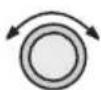

- If you selected Manual Magnetic Variation, turn the LARGE knob to move to the variation value field. Select the variation value with the SMALL knob.
MAC VARIATION: MANUAL 19 °E
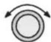

ENTER
- Turn the LARGE knob to move to the E or W direction field. Turn the SMALL knob to select E or W and then press ENTER. The MSG annunciator will flash and a message will note that you have selected manual magnetic variation.
MAG VARIATION MANUAL 19°E
Flight Timer Trigger
The following procedure is used to edit the flight timer trigger speed. The flight timer may be set to start at power-up, or when the ground speed exceeds from 10 to 500 knots. The default (factory) setting is 60 knots. The feature may also be turned off.

SEL
- In the Navigation section of the System function, turn the LARGE knob to reach the Flight Timer Trigger page. Press SEL.
FLIGHT TIMER TRIGGER AT 60 KTS

ENTER
- Turn the SMALL knob to select the speed value, "At Power On," or "OFF" and then press ENTER.
FLIGHT TIMER TRIGGER AT 50 KTS
Direct-To Entry Options
When you use Direct-To, the Active flight plan (and the FROM, TO, NEXT information) is automatically updated. The “May Clear” and “Never Clears” options affect your flight plan.
If you use Direct-To to center the CDI needle for the current “TO” waypoint, or skip past the TO waypoint to another waypoint already in the Active flight plan, the current leg number of the Active flight plan will be updated, if needed, so that the Direct-To waypoint matches the current “TO” waypoint. In these cases, the Direct-To Entry Option is not a factor.
The Direct-To Entry Option becomes a factor if you go Direct-To a waypoint which is not in the Active flight plan.
With the May Clear Direct-To Entry Option, the Direct-To waypoint will be inserted in the Active flight plan, and all of the other waypoints will be deleted from the Active flight plan, including approaches.
With the Never Clears Direct-To option, the Direct-To waypoint is inserted before the current TO waypoint. This is the normal, default setting. Use this setting if you are using approaches.
The May Clear option is useful for the pilot who uses the Direct-To function for the majority of flight planning, and doesn't want to be bothered with a steadily increasing number of waypoints in the Active flight plan. The Never Clears option is useful when you need to respond to a change ATC clearance (i.e., N1234A cleared direct ABXYZ intersection, rest of route unchanged), resuming the previously entered flight plan at a later time.
The default setting for the Direct-To Entry is May Clear. The Apollo GX retains the last Direct-To Entry Option setting when it is powered up.
- In the Navigation section of the System function, turn the LARGE knob to reach the Direct-To page and then press SEL.
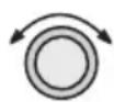
SEL
DIRECT-TO ENTRY NEVER CLEARS ACTIVE PLAN

ENTER
- Turn the SMALL knob to select "May Clear" or "Never Clears" and then press ENTER.
DIRECT-TO ENTRY MAY CLEAR ACTIVE PLAN
CDI Scaling
The CDI Scaling option allows you to select manual or automatic full scale deflection of the internal CDI. Manual full scale deflection options include: 0.30 nm, 1.00 nm, and 5.00 nm. Automatic scaling will use 5.00 nm as the setting. In an enabled approach operation (GX50/60), scaling is locked in automatic and will change to the appropriate scale according to your distance to the destination waypoint.

SEL
- In the Navigation section of the System function, turn the LARGE knob to reach the CDI Scaling page and then press SEL.
00 31 00 32 00 33 00 34 00 35 00 36 00 37 00 38 00 39 00 40 00 41 00 42 00 43 00 44 00 45 00 46 00 47 00 48 00 49 00 50 00 51 00 52 00 53 00 54 00 55 00 56 00 57 00 58 00 59 00 60 00 61 00 62 00 63 00 64 00 65 00 66 00 67 00 68 00 69 00 70 00 71 00 72 00 73 00 74 00 75 00 76 00 77 00 78 00 79 00 80 00 81 00 82 00 83 00 84 00 85 00 86 00 87 00 88 00 89 00 90 00 91 00 92 00 93 00 94 00 95 00 96 00 97 00 98 00 99 1
5.00MM
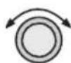
- If you chose manual, turn the LARGE knob to move to the distance value.
OPT SCALIND
Manual
5.013.4M

- Turn the SMALL knob to select the distance value and then press ENTER.
ENTER
DIFT APPLI END
Manual
1.00MM
System Information
The System Information area provides the following pages: Software and Database Version, Display test, Owner Info, and Date and Time, .
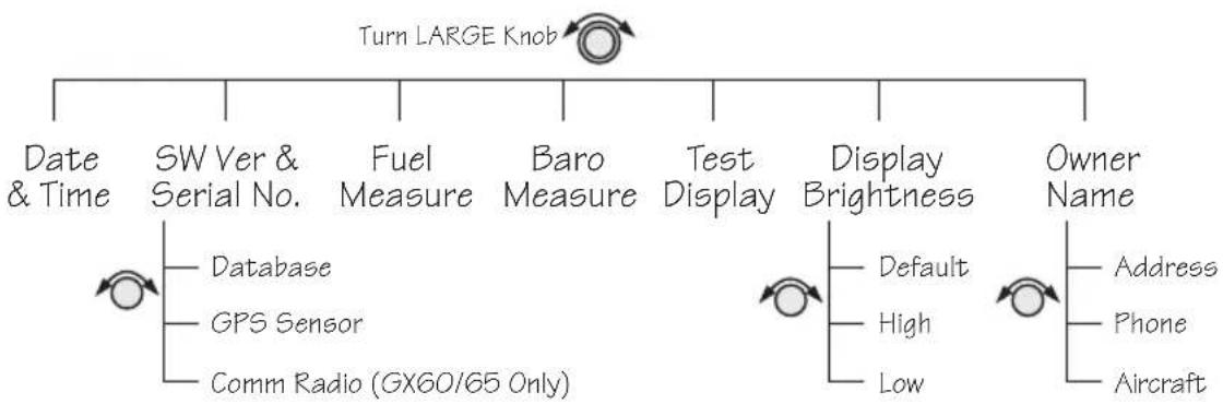
flowchart
graph TD
    A["Turn LARGE Knob"] --> B["Date & Time"]
    A --> C["SW Ver & Serial No."]
    A --> D["Fuel Measure"]
    A --> E["Baro Measure"]
    A --> F["Test Display"]
    A --> G["Display Brightness"]
    A --> H["Owner Name"]
    C --> I["Database"]
    C --> J["GPS Sensor"]
    C --> K["Comm Radio (GX60/65 Only)"]
    G --> L["Default"]
    G --> M["High"]
    G --> N["Low"]
    H --> O["Address"]
    H --> P["Phone"]
    H --> Q["Aircraft"]
Date and Time
- Press the SYS key. Turn the LARGE knob to reach the System Information function and press ENTER. Turn the LARGE knob to the Date and Time page.
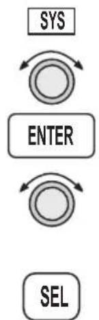
flowchart
graph TD
    A["SYS"] --> B["ENTER"]
    B --> C["SEL"]

text_image
SYSTEM INFO PRESS ENTER- This information is provided by the GPS satellites and you will not usually need to change it. Press SEL to reset the date and time. The Day value will flash.
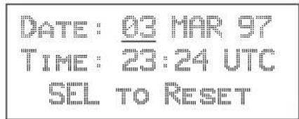
text_image
DATE: 03 MAR 97 TIME: 23:24 UTC SEL TO RESET- Turn the SMALL knob to choose the day.

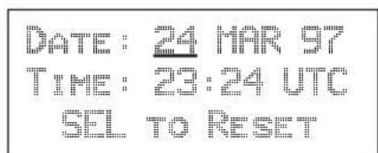
text_image
DATE: 24 MAR 97 TIME: 23:24 UTC SEL TO RESETSystem Functions
- Turn the LARGE knob to move to the Month value. Turn the SMALL knob to choose the month.
DATE: 24 APR 97 TIME: 23:24 UTC SEL TO RESET
- Turn the LARGE knob to move to the Year value. Turn the SMALL knob to choose the year.
DATE: 24 APR 97 TIME: 23:24 UTC SEL TO RESET
- Turn the LARGE knob to move to the Time-Hours value. Turn the SMALL knob to choose the hours. Turn the LARGE knob to move to the Time-Minutes value. Turn the SMALL knob to choose the minutes.
DATE: 24 APR 97 TIME: 17:34 UTC SEL TO RESET
ENTER
- After completing your entries, press ENTER.
Software Version
The Software Version function provides version information about the Apollo software, serial number, database, GPS sensor, display software.

- In the System Information section of the System function, turn the LARGE knob to reach Software Version page.
APOLLO GX-SERIES SN VERS X.X SN: 1234567 †

- Turn the SMALL knob cw one click to view the Database Version page.

text_image
AMERICAS DB EXPIRES MM/DD/YY VERSION: X.XX
- Turn the SMALL knob cw one click to view the GPS Software Version page.
text_image
GPS SENSOR SN VERSION X: X PN: 123456789Fuel Measure Units (GX50/60 Only)
The GX50/60 allows you to choose the units of measure for your fuel displays. Fuel units may be displayed as US Gallons (USG), Imperial Gallons (IMG), Liters (L), Pounds (LBS), or Kilos (KGS).

- In the System Information section of the System function, turn the LARGE knob to reach the Fuel Measure page.

text_image
FUEL MEASURE USG US GALLONS
- Press SEL to enable selection. Turn the SMALL knob to choose the desired units and then press ENTER.

ENTER
Barometric Measure Units (GX50/60 Only)
This function allows you to choose the units of measure for the Local Altimeter Settings. The choices are inches (“) or millibars (MB).
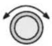
- In the System Information section of the System function, turn the LARGE knob to reach the Baro Measure page.
BARO MEASURE USG US SALONS
- Press SEL to enable selection. Turn the SMALL knob to choose the desired units and then press ENTER.

Test Display
The Test Display page allows you to test the display segments. In the System Information section of the System function, turn the LARGE knob to reach the Test Display page. Press ENTER to start the test. Pressing any key or turning any knob will cancel the test.
To Test Display Press ENTER
Display Brightness
The display brightness of your Apollo GX is automatically controlled by a photocell and set to provide good viewing for ambient light conditions. At times you may want to manually control the display brightness. Default is the automatic mode.
- In the System Information section of the System function, turn the LARGE knob to reach the Display Brightness page. Press SEL to start selection.
DISPLAY BRIGHTNESS DEFAULT

ENTER
- Turn the SMALL knob to choose Default, High, or Low. Press ENTER to store the desired choice. Your choice is kept until you change it.
Viewing Owner Information
The Owner Information function allows the user to enter their Name, Address, City, Phone, and Aircraft. As a security feature, the user must enter a password to enable editing of the Owner Information.

- In the System function, turn the LARGE knob to reach the Owner Information page.
OWNER NAME: LILIBUR HIGHT


- Turn the SMALL knob to view the Owner Information.
OWNER ADDRESS: 2345 TURNER RD SALEM OR USA

- Turn the SMALL knob to view the Owner Phone.
OWNER PHONE: 5410-581-0101

- Turn the SMALL knob to view the Owner Aircraft.
AIRCRAFT: MY AIRPLANE
Editing Owner Information
It is necessary to enter a password before editing owner information. Editing is then enabled until the unit is turned off.
SEL
- Start editing by pressing SEL.
USER MUST FIRST ENTER PASSWORD:

- The password entry page is then ready. Select the characters with the SMALL knob and move to the next character to the right by turning the LARGE knob cw. When you turn the LARGE knob, the last character is erased to enforce secrecy of your password.
ENTER OWNER PASSWORD :
ENTER
- Press ENTER when you finish entering the password. If the entered password does not match the true password, you will be given another chance. You can cancel by pressing SEL. If the entered password matches, the screen flashes a message for about two seconds followed by the last displayed owner info page. Once the correct password is entered, editing is allowed until your Apollo GX is turned off. Press SEL to start editing.
PASSWORD MATCHED EDITING ENABLED

- Select the characters with the SMALL knob and move to the next character to the right by turning the LARGE knob cw. Press ENTER to save the information.

- Turn the SMALL knob to go to the next Owner Information page you want to edit. Press SEL to start editing. Select the characters with the SMALL knob and move to the next character to the right by turning the LARGE knob cw. Press ENTER to save the information.
GPS Sensor
The GPS Sensor selection provides information about GPS satellite health, the GPS satellites available, information on each satellite, GPS Time, and GPS Reset. See the Introduction to GPS section on page 1 for more information on how GPS works.
Turn SMALL Knob


flowchart
graph TD
    A["Healthy & Visible Satellites"] --> B["GPS Position"]
    B --> C["Satellite Search Status"]
    C --> D["Satellite Search Status"]
    D --> E["GPS Time"]
    E --> F["GPS Normal Reset"]

ENTER
- In the System function, turn the LARGE knob to reach the GPS Sensor page. Press ENTER.
GPS SENSOR
PRESS ENTER
- The GPS Health page is shown if GPS information is received. The GPS number and dimension (2D, 3D, or no position), number of healthy, and number of visible satellites are shown.
GPS 3D POSITION
12 000 12 000 12 000 12 000 12 000 12 000 12 000 12 000 12 000 12 000 12 000 12 000 12 000 12 000 12 000 13 000 13 000 13 000 13 000 13 000 13 000 13 000 13 000 13 000 13 000 13 000 13 000 13 000 13 000 13 15 13 15 13 15 13 15 13 15 13 15 14 14 14 14 14 14 14 14 14 14 14 14 14 14 14 14 14 14 14 14 14 14 14 14 14 14 14 14 14 14
VISIBLE SATS 8

- Turn the SMALL knob to view the GPS Satellites Used for Position fixes page. SV means space vehicle, which is the same as a GPS satellite in this case.
GPS 5VS FOR FIX
28, 31, 27, 26,
19, 07, 02, 18

- Turn the SMALL knob again to view the GPS Satellite Status, Elevation, SNR, and Azimuth page. Continue turning the SMALL knob to view information about each available satellite.
SV01 STATUS SRCHELE 21° SIG 123AZIMUTH 043°
- Elevation (Ele)- The angle of a GPS satellite above the horizon.
• Signal Strength (Sig) - The relative strength of the received signal from the satellite - Azimuth - an arc, as measured clockwise from magnetic or true north.
Satellite Search Status
• SRCH
Receiver is searching for the satellite
• ACQR
receiver is acquiring the signal
- TRCK
receiver has locked to the satellite's data sequence
• DATA
receiver is locked and downloading data from the satellite
Until data is received by the receiver, a display may look like the following:
THIRD SAT NOT AVAILABLE
GPS Date and Time Page
In the GPS Sensor Information function, turn the SMALL knob to view the GPS Date and Time page. This page is not shown when using the Simulator.

Resetting the GPS receiver resends current time, date, and position to the GPS receiver. This forces a new search of the satellites. Use this function when it appears that the GPS receiver is locked up or seems to be taking far longer than it should to lock onto the signals.

ENTER
In the GPS Sensor Information function, turn the SMALL knob to view the GPS Normal Reset page.
Press ENTER to reset the GPS receiver.
PRESS ENT TO DO A NORMAL GPS RESET
Miscellaneous Sensors
The Miscellaneous Sensor section of the System function displays information concerning the Fuel/Air Data Sensor (F/ADS), fuel sensor, and altitude encoder when they are installed. The F/ADS includes a fuel sensor and altitude encoder. The F/ADS monitors fuel flow, air speed, outside air temperature/pressure, and magnetic heading. The F/ADS data is used to compute true air speed, pressure altitude, density altitude, heading, wind direction/velocity, rate of climb, and fuel usage. Turn the LARGE knob to choose the sensor. Turn the SMALL knob to view additional available information.
Turn LARGE Knob

Encoding Altimeter
Air Data Info
Fuel Info
Pressure Altitude

True air speed, Indicated air speed

True air temp, outside air temp, mach
Turn SMALLKnob
Density altitude, pressure altitude, rate of climb
Endurance, nm/gal, remaining fuel
Magnetic heading, desired heading, turn rate
Range, burn rate, gal used
Wind direction (true & mag) wind speed
Right engine, burn rate, gal used
Left engine, burn rate, gal used
Full capacity, reserve, message at time
Fuel measure
Encoding Altimeter
The Encoding Altimeter information is provided when a suitable device has been installed. The Pressure Altitude value is provided by the encoding altimeter is shown on this display. This is the current altitude without barometric pressure adjustment.

text_image
ENCODING ALTIMETER PRES ALT: 2100FTAir Data Info If the Air Data Sensor is installed, the following information is available.
Air Speed
True Airspeed - speed of the aircraft relative to the surrounding air speed.
Indicated Air Speed - Speed of the aircraft as shown on the airspeed indicator.

text_image
AIR DATA INFO TRU AIRSP 163KTS IND AIRSP 149KTSAir Temperature
True Air Temperature - Temperature compensated for wind chill factors.
Outside Air - Temperature without compensation for wind chill.

text_image
TRUE AIR ° 10°C OUT AIR ° 8°C MACH 0.242Altitude and Rate of Climb
Density Altitude, Pressure Altitude, and rate of climb.

text_image
DENS ALT 7390FT PRES ALT 5280FT ROC +0020FT/MINHeading and Turn Rate
Magnetic Heading, Desired Heading, Turn Rate in degrees per second, and direction of the turn.
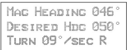
text_image
MAC HEADING 046° DESIRED HDG 050° TURN 09°/SEC RWind Direction and Speed
True Wind Direction, Magnetic Wind Direction, and the outside Wind Speed are displayed.
| HIND DIR 000°TRU |
| HIND DIR 342°MAG |
| HIND SPD 15KTS |
Fuel Info An installed Fuel Data Sensor will provide the following information.
Fuel Endurance
• Estimated fuel Endurance based on the current amount of fuel in the regular (nonreserve) tanks at the current burn rates
• Nautical miles per fuel unit
• Remaining fuel (not including reserves)
| ENDURANCE 20:18 |
| NM PER USG ... |
| REMAIN 452USGT |
Range, Burn Rate, and Fuel Used
• Estimated Fuel Range based on current fuel in nonreserve tanks, current burn rate, and current speed
• Current Burn Rate in fuel units per hour
• Total Fuel Used since power up
| RANGE | NM |
| BURN | 22.5USG/HR |
| USED | 21usc |
Right Engine Fuel
- Burn rate for the right engine in fuel units per hour
• Amount of fuel used by the right engine since power up
RIGHT ENGINE BURN 17.7USG/HR USED 11USC
Left Engine Fuel
- Burn rate for the left engine in fuel units per hour
• Amount of fuel used by the left engine since power up
LEFT ENGINE BURN 16.2BUSG/HR USED 10USG
Total Fuel
• Total fuel all tanks hold
- Reserve fuel amount
• Fuel Warning message time period
The values on this display are user selectable. Press SEL to start editing. Turn the LARGE and SMALL knobs to edit the values. Press ENTER when you have entered the appropriate values.
SEL


ENTER
FULL 00500USC RESERVE 00025USC MESSAGE AT 30MIN
Fuel Measure
The GX50/60 allows you to choose the units of measure for your fuel displays. Fuel units may be displayed as US Gallons (USG), Imperial Gallons (IMG), Liters (L), Pounds (LBS), or Kilos (KGS).
FUEL MEASURE
USEC
US GALLONS
SEL

ENTER
Press SEL to enable selection. Turn the SMALL knob to choose the desired units and then press ENTER.
Message Function
Message function is responsible for warning the user of changing conditions which require immediate attention. Press the MSG smart key to view the message. Press the MSG key again to return to the previous function. However, if a new message occurs, pressing MSG will not return to the previous function until all new messages have been viewed.
When a new message exists, the MSG annunciator flashes on and off approximately twice per second, until either the user views the new message, or the condition causing the message goes away. If multiple messages exist, the annunciator continues to flash until all new messages have been viewed.
Most new messages continue to be relevant following viewing of the new message, and are put into the old message list, where they remain until the condition causing the message goes away. Other messages are cleared from the message list as soon as they are viewed (they don't become old messages). The decision whether a new message becomes an old message after viewing is described for each individual case below in the List of Messages section. The formats of all messages are the same if they are in the new or old message list.
Turn LARGE Knob


flowchart
graph TD
    A["Turn SMALLKnob"] --> B["Message 1"]
    A --> C["Message n"]
    B --> D["•"]
    C --> E["•"]
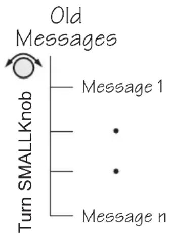
flowchart
graph TD
    A["Turn SMALLKnob"] --> B["Message 1"]
    A --> C["Message n"]
    B --> D["Old Messages"]
    C --> D
Message Function
While any old message exists, the MSG annunciator remains steadily on at all times unless new messages arrive or all old message conditions go away.
The home page in message mode is the first new message, if one exists, or the New Message Summary page if no new messages exist.
New Messages
The New Message page shows how many new messages are stored.
MSG
- Press MSG. Turn the LARGE knob to switch between New and Old Messages.
2 NEW MESSAGES TURN LARGE KNOS For Old MScs

- Turn the SMALL knob to view each message. Press MSG a second time to return to the previous function.
MSG
Old Messages
The Old Message page shows how many old messages are stored.
MSG
- Press MSG. Turn the LARGE knob to switch between New and Old Messages.
2 OLD MESSAGES TURN LARGE KNOB FOR NEW HOGS

- Turn the SMALL knob to view each message. Press MSG a second time to return to the previous function.
MSG
Messages The following is a summary of the conditions that cause a message warning, and examples of the messages generated for each condition.
Special Use Airspace Messages
Following is a list of the types of airspace messages which can be generated. All of the airspace messages become old messages after they are viewed. The Airspace Messages are unique in Message Mode in that they are the only messages which the INFO key is used to find out more information concerning the message. Values for the ceiling and floor may be any positive number less than 100,000 feet. Values may also be Unlimited, Ground, FL (Flight Level, followed by a number, such as, 050), Unknown, or NOTAM (Notice To Air Men).
CEIL: 8000" MSL FLOOR: 800" MSL BRC 008*+58.4NM
SOON
This condition occurs when penetration of the airspace is within 10 minutes (or user-selected limit in System Mode)
WITHIN 10 MIN OF GABBS CENTRAL MOR
CLOSE
This condition occurs when the airspace is less than 2 nm (or user-selected limit in System Mode, see page 4-11).
WITHIN 2 NM OF SUNDANCE MOR
CLOSE Altitude
This condition occurs when the airspace boundary is within 500 feet, or a user-selected limit in the System function.
WITHIN 500' OF NORTON AFB CLASS C
INSIDE
This condition occurs when the plane penetrates the airspace.
INSIDE OF SAN DIEGO Class B
Empty TO Waypoint: Cannot Compute Nav
Anytime the current To waypoint is empty, this message is generated. It becomes an old message after viewing.
EMPTY TO HPT: CANNOT COMPUTE NAV INFO
GPS Self Test Failure
If the GPS self-test fails, a message displays indicating the cause of the failure in four hexadecimal digits. It becomes an old message after viewing.
GPS SELF TEST FAILURE: JFFF SERVICE NEEDED
GPS Sensor Lat/Lon Failure
When the GPS sensor cannot compute the latitude and longitude, the following message displays. It becomes an old message after viewing.
GPS POSITION SENSOR CANNOT COMPUTE LAT/LON
GPS RAIM Not Available
When RAIM detection is not available for the GPS sensor, a warning is generated. The current flight phase is displayed first (Terminal, En Route, or Approach). Approach warnings are for the GX50/60 only. Messages become an old message after viewing.
EN ROUTE GPS RAIM NOT AVAILABLE
GPS RAIM Position Error
When RAIM detection is available for the GPS sensor and it detects a RAIM alarm, a warning is generated and Nav data will be flagged as invalid. The current flight phase is displayed first (Terminal, En Route, or Approach). Approach warnings are for the GX50/60 only. It becomes an old message after viewing.
TERMINAL GPS RAIM ALARM POSITION ERROR
GPS Communication Failure
This message appears when communications fail between the Apollo GX and the GPS engine. The message will remain if there is a real problem. You may also see this message if you press the SKIP key during startup before the GPS engine was initialized, in which case there is no problem and the message will go away.
GPS COMMUNICATIONS FAILURE
GPS HDOP Position Error
When the HDOP for the GPS sensor exceeds current flight phase HDOP requirements, a warning is generated and Nav data will be flagged as invalid. The current flight phase is displayed first (either Terminal or En route). Approach warnings are for the GX50/60 only. Messages become an old message after viewing.
TERMINAL GPS HDOP POSITION ERROR
Parallel Track/Approach Conflict (GX50/60 Only)
This message appears when the current parallel track conflicts with the selected approach.
PTK - APPROACH CONFLICT. PRESS ENT TO STOP PTK
Enable Approach (GX50/60 Only)
This message is generated when an approach is loaded, but not enabled.
PRESS ENTER TO ENABLE APPROACH
Approach Enabled Too Late (GX50/60 Only)
When an approach is enabled too close to the FAF waypoint, the following message is created.
ABORT APPROACH APPROACH ENABLED < 2NM FROM PAF
Set Barometer (GX50/60 Only)
When an approach is enabled, you are prompted to enter the local altimeter setting.
ENTER LOCAL ALTIMETER SETTING 29.92IN
No Valid Altitude Input for Approach (GX50/60 Only)
An approach is not valid unless an altitude value is available.
ABORT APPROACH NO VALID ALTITUDE INPUT
Approach RAIM Unavailable (GX50/60 Only)
An approach is not valid unless RAIM is available.
ABORT APPROACH GPS RAIN NOT AVAILABLE
RAIM Predict Too Late (GX50/60 Only)
When the RAIM prediction occurs too close to the FAF, the following message appears.
ABORT APPROACH RAIM PREDICT NOT COMPLETED BY FAF
Lat/Lon Position Jump (GX50/60 Only)
LAT/LON POSITION JUMP OUTPUTS FLAGGED
Altitude Range Error
When the altitude encoder reports an altitude that is out of range, the following message is created.
ALTITUDE OUT OF RANGE
Altitude Encoder Communications Failure
This message appears when communications fail between the Apollo GX and the altitude encoder.
ALTITUDE ENCODER COMMUNICATIONS FAILURE
Fuel/Air Data Sensor Communications Failure
This message appears when communications fail between the Apollo GX and the fuel air data computer.
FUEL / AIR DATA COMMUNICATIONS FAILURE
Low Fuel
This message appears when the fuel air data computer reports that remaining fuel is below the user-selected threshold value.
LOW FUEL WARNING LESS THAN 30 MIN CHECK TANKS
Arrival At Hold Altitude
You have arrived at the selected Hold Altitude.
ARRIVAL HT 2500FT TARGET HOLD ALTITUDE
Outside Hold Altitude Buffer
You have gone above or below the selected Hold Altitude Buffer.
ALTITUDE ALERT 500FT ABOVE HOLD ALTITUDE
Start Auto Descent
BEGIN DESCENT TO NOONS 500FT/MIN 130KTS
Arrival At Auto Descent Altitude
ARRIVAL AT 2000FT TARGET DESCENT ALTITUDE
Arrival At The TO Waypoint
The arrival message is generated when you are within 36 seconds of arrival at the current TO waypoint, except when turn anticipation is active. The arrival message is cleared after viewing it; it does not become an old message after viewing. The arrival condition will also go away without viewing the message after crossing the angle bisector. In the example below, WPT 2 is the TO waypoint. When the aircraft crosses the dotted line, WPT 3 will become the TO waypoint.
This form of the Arrival Alert is provided when not holding at the current TO waypoint. When flying an approach DME Arc, then waypoint is automatically placed on hold. The hold is automatically removed upon arriving at the TO waypoint, prior to receiving the arrival alert.

flowchart
graph TD
    A["WPT 1"] -->|Leg 1| B["飞机"]
    B -->|From| C["WPT 2"]
    C -->|Leg 2| D["WPT 3"]
    D -->|To| E["End"]
Apollo GX with F/ADS Wind Info
FIRE I VIL : SLE
In addition to the arrival waypoint identifier, the next leg's desired track is shown when available; otherwise, it is dashed. If wind factors (from the Fuel/Air Data Sensor) and a next waypoint are available, the desired heading is also shown on line three; otherwise, line three is blank. DTK is shown for your next leg when Turn Anticipation is used.
Arrival at Inbound Course
When using the Vector to Final, DME Arc Assist, or the Procedure Turn functions, the arrival message will alert you when the course line has been intercepted. The desired track for your next waypoint will be displayed.
COURSE INTERCEPT
NEXT DTK: 321
Holding at the TO Waypoint
This form of the Arrival Alert is provided when holding at the current TO waypoint.
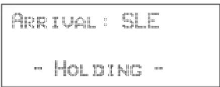
text_image
ARRIVAL : SLE - HOLDING :Next Leg is DME Arc
This type of Arrival Alert is provided when the next TO waypoint is the end of a DME Arc holding at the current TO waypoint. Press ENTER to transition directly to the NAV mode DME Arc Assist page.

text_image
ARRIVAL: SLE DME NEXT-USE ARC ASSIST? ENTERTO Waypoint Sequence
When a waypoint sequence occurs and the user has not viewed the arrival alert, the following alerts are provided if you are traveling faster than 5 knots (this reduces the chance of nuisance alerts). The new waypoint, bearing and desired track are provided. This message does not become an old message after viewing.
Normal Sequence
This type of Sequence Alert is provided when the next TO waypoint is not the end of a DME Arc.
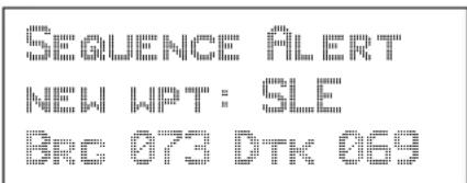
text_image
SEQUENCE ALERT NEW WPT: SLE BRC 073 DTK 069DME Arc Sequence (GX50/60 Only)
This form of Sequence Alert is provided when the next TO waypoint is the end of a DME Arc in a nonprecision approach. Press ENTER to transition directly to the NAV mode DME Arc Assist page.
SEQUENCE ALERT DME NEXT-USE ARC ASSIST? ENTER
Auto OBS Crossing Holding Waypoint
When a waypoint on hold is crossed to the From side the first time, the following message is provided. This message is not created when you cross the MAP. If you press ENTER, the OBS Desired Track screen is displayed. This message does not become an old message after viewing.
PUSH ENTER TO SET OBS COURSE : NAV/MAP TO EXIT
User Database Memory Loss
This message indicates that one or more user waypoints or user-defined comments had a checksum error. This message is cleared after the message is viewed.
USER DATABASE MEMORY LOSS: 2 DELETED
Flight Plan Memory Loss
This message indicates that one or more flight plans had a checksum error. This message is cleared after the message is viewed.
FLIGHT PLAN MEMORY LOSSES 1 DELETED
User Memory Failure
This message indicates that one or more user settings were not within valid limits at power-up and needed to be reset. This message is cleared after the message is viewed.
MEMORY FAILURE USER SETUPS HAVE BEEN RESET
Database Expired
This message indicates that the datacard expiration date is before the current UTC date. This message is cleared after the message is viewed.
AMERICA DATABASE EXPIRES 06/30/97 VERSION: X.XX
Database Invalid
This message indicates that the datacard memory has been corrupted. It becomes an old message after being viewed. Turn the unit off. Pull out the data card and reinsert it. If the problem persists, contact your dealer or the factory for service.
DATABASE INVALID ID CHECK DATA CARD
Manual Magnetic Variation
This message indicates that magnetic variation is on a manual setting. This occurs when the database is not valid, or when the user selects manual magnetic variation in System Mode. It becomes an old message after being viewed.
USING MANUAL Fig. 1: 13·E
Low Internal Battery Voltage
This message is generated when low internal battery voltage is detected. It becomes an old message after being viewed. Battery voltage is checked every 15 seconds. This battery backs up the memory for information added by the user, such as user waypoints and stored flight plans.
LOW BATTERY VOLTAGE: UNIT NEEDS SERVICE
High Battery Voltage
This message is generated when high or zero battery voltage is detected. It becomes an old message after being viewed. Battery voltage is checked every 15 seconds. The unit must be returned to the factory for service. Continued operation is NOT recommended.
INTERNAL BATTERY FAILURE: TURN OFF UNIT/NEEDS SRVC!
Countdown Timer Expired
This message is generated when the Countdown Timer (which must have been counting down) goes to 0. The message is cleared when the user views the message or reactivates the Countdown Timer.
COUNTDOWN TIMER EXPIRED
Approach Basics (GX50/60)
The Apollo GX50/60 may be used to navigate GPS non-precision approaches. These consist of overlay approaches, GPS approaches which overlay an existing non-precision approach procedure such as a VOR, an RNAV, or an NDB approach, and GPS-only approaches. GPS approaches may overlay any type of non-precision approach procedure except for localizer, LDA, and SDF approaches.
GPS approaches may be either Phase II or Phase III overlay, or named GPS-only approaches. The major difference in the overlay approaches is that for a Phase II approach, the underlying approach NavAid(s) must be operating and the aircraft must be equipped for the underlying approach. It is not necessary to monitor the underlying NavAid(s). A Phase III GPS approach may be conducted even if the underlying NavAid(s) are not operating.
Introduction There are three general areas of operation (see the diagram on page 9-3): En Route, Approach Transition, and Approach Active.
En Route
En route operations describe what you do to set up your approach information before you are within 30 nm of destination airport and prior to enabling your approach. Load your approach to the active flight plan. You can load the approach in the Flight Plan function, or as a short cut, press SEL in the Nav function or while viewing the moving map. At 30 nm your Apollo GX will ask if you want to enable approach, press the ENTER button. Then, enter the local altimeter setting. If you are less than 30 nm from your destination when you load an approach, you will be prompted immediately to enable it.
Approach Transition
Approach Transition operations occur after you enable approach operation. The APPRCH annunciator will turn on. The CDI sensitivity will gradually scale from 5.0 to 1.0 nm full scale per side automatically. The IAF is usually in the Approach Transition operation area. The ACTIVE annunciator will start flashing when you are within 3 nm inbound to the FAF and not on hold (sequencing suspended). When you are 2 nm from the FAF, CDI sensitivity will gradually scale from 1.0 to 0.3 nm full scale per side automatically.
Approach Active
Approach Active operation begins when you cross the FAF and ends when you cross the MAP. The CDI is at 0.3 nm full scale per side. The OBS/HOLD Annunciator is on steady. The ACTIVE annunciator is on steady. If the ACTIVE annunciator is not on steady, do NOT continue the approach.
Approach Transition
Approach Transition operation begins again when you cross the MAP. Decide whether you are going to land or perform a missed approach. If you are performing a missed approach procedure, press the OBS/HOLD annunciator to enable waypoint sequencing. The CDI will scale back to 1.0 nm.
Waypoint Arrival Alert
A standard Waypoint Arrival Alert message is generated when you reach each approach waypoint. Press the MSG button to view and acknowledge the message. Press MSG again to return to the previous display. The Waypoint Alert indicates that you are close (approximately 1 nm for every 100 nm/h or about 36 seconds) to the destination waypoint.

CAUTION
The Apollo GX and the U.S. GPS Satellites use the World Geodetic System 1984 (WGS-84) horizontal datum for latitudes and longitudes. Approach plate or approach procedure data must be referenced to the WGS-84 or North American Datum 1983 (NAD-83) in order to use the approach. NAD-83 is for all practical purposes identical to the WGS-84 datum. All published U.S. and Canadian approach charts meet this criterion. Prior to using the Apollo GX for any GPS approach other than a published U.S. or Canadian approach, you must first verify that the approach charts and approach waypoints use the WGS-84 or NAD-83 reference system. If the approach data is referenced to any other coordinate system, it can result in an unsafe position error.
The Apollo GX database contains approach information. It is very important that the pilot verify that approach data is current prior to use. The approach data contained in the Apollo GX does not replace or eliminate the need for Approach Plates or published Approach Procedures.
Some approach procedures may not be suitable for the Apollo GX operational characteristics and may be omitted from the Apollo GX database. Since an approach must be in the database in order to be selected and flown using the Apollo GX, it is good pre-flight practice to make sure that the database contains anticipated approaches. Always refer to the charts for a given approach before performing the approach.

flowchart
graph LR
    A["Enroute Operation"] --> B["Approach Transition Operation"]
    B --> C["Approach Active Operation"]
    C --> D["Approach Transition Operation"]
    D --> E["MAHP"]
    E --> F["Proceed to Selected Waypoint"]
    F --> G["CDI Scale Transitions 0.3 nm to 1.0 nm"]
    G --> H["MAHP"]
    H --> I["CDI Scale Transitions 1.0 to 0.3 nm"]
    I --> J["MAHP"]
    J --> K["CAPIA"]
    K --> L["CAPIA"]
    L --> M["CAPIA"]
    M --> N["CAPIA"]
    N --> O["CAPIA"]
    O --> P["CAPIA"]
    P --> Q["CAPIA"]
    Q --> R["CAPIA"]
    R --> S["CAPIA"]
    S --> T["CAPIA"]
    T --> U["CAPIA"]
    U --> V["CAPIA"]
    V --> W["CAPIA"]
    W --> X["CAPIA"]
    X --> Y["CAPIA"]
    Y --> Z["CAPIA"]
    Z --> AA["CAPIA"]
    AA --> AB["CAPIA"]
    AB --> AC["CAPIA"]
    AC --> AD["CAPIA"]
    AD --> AE["CAPIA"]
    AE --> AF["CAPIA"]
    AF --> AG["CAPIA"]
    AG --> AH["CAPIA"]
    AH --> AI["CAPIA"]
    AI --> AJ["CAPIA"]
    AJ --> AK["CAPIA"]
    AK --> AL["CAPIA"]
    AL --> AM["CAPIA"]
    AM --> AN["CAPIA"]
    AN --> AO["CAPIA"]
    AO --> AP["CAPIA"]
    AP --> AQ["CAPIA"]
    AQ --> AR["CAPIA"]
    AR --> AS["CAPIA"]
    AS --> AT["CAPIA"]
    AT --> AU["CAPIA"]
    AU --> AV["CAPIA"]
    AV --> AW["CAPIA"]
    AW --> AX["CAPIA"]
    AX --> AY["CAPIA"]
    AY --> AZ["CAPIA"]
    AZ --> BA["CAPIA"]
    BA --> BB["CAPIA"]
    BB --> BC["CAPIA"]
    BC --> BD["CAPIA"]
    BD --> BE["CAPIA"]
    BE --> BF["CAPIA"]
    BF --> BG["CAPIA"]
    BG --> BH["CAPIA"]
    BH --> BI["CAPIA"]
    BI --> BJ["CAPIA"]
    BJ --> BK["CAPIA"]
    BK --> BL["CAPIA"]
    BL --> BM["CAPIA"]
    BM --> BN["CAPIA"]
    BN --> BO["CAPIA"]
    BO --> BP["CAPIA"]
    BP --> BQ["CAPIA"]
    BQ --> BR["CAPIA"]
    BR --> BS["CAPIA"]
    BS --> BT["CAPIA"]
    BT --> BU["CAPIA"]
    BU --> BV["CAPIA"]
    BV --> BW["CAPIA"]
Approach Procedure
There are three general types of Apollo GX operation:
- En Route
√ Load Destination Waypoint
√ Load Approach Information
• Approach Transition (or Approach Enabled)
√ Enable approach (Method 1 or 2)
√ 30 nm from Destination Airport
√ Initial Approach Fix
√ Final Approach Fix
- Approach Active
√ Crossing the Final Approach Fix
√ Missed Approach Point
When conducting an approach, your Apollo GX will progress from En Route to Approach Transition when the pilot enables the approach, then to Approach Active, and possibly back to Approach Transition in the event of a missed approach.
En Route Operations
En route operations describe all operations prior to 30 nm from your destination airport. Your Apollo GX is providing en route operation whenever the Approach annunciator light is not on. The default CDI sensitivity for en route is 5.0 nm; however, you may manually select other CDI sensitivities. Generally, you will select your destination airport prior to departure or while en route, and you will usually select and load an anticipated approach from the database into your active flight plan while en route.
Note
An approach can only be selected for an airport when it is the last waypoint in your active flight plan.


flowchart
graph TD
    A["Enroute Operation"] --> B["CDI Scale = 5nm"]
    B --> C["30nm to Airport"]
    D["Load Approach to Active Flight Plan"] --> E["MSG Annunciator Flashes. Enable Approach? Press ENT and then Enter Local Altimeter Setting"]
Load a Destination Airport
The destination must be an airport.
FPL
- Load your flight plan. You may activate or edit an existing flight plan. Press the FPL key to reach FLIGHT PLAN mode.
If the desired flight plan is active, go to the next section "Load Approach Information."

- If the desired flight plan is not displayed, turn the LARGE, outer knob to display the desired flight plan.
ROUTE 1 44.2NM DEST NPT: PDX INACTIVE
SEL
- Press SEL. "Activate" will flash. Press ENTER to activate the selected flight plan.
ENTER
ROUTE 1 44.2NM DEST HPT: PDX ACTIVATE?
SEL
Load Approach Information
- When a flight plan is active, press SEL while in the Nav function or the Moving Map to go directly to this display. In the Flight Plan function with the active flight plan displayed, press SEL to reach the "Load Approach?" selection.
EARTIVE 44.24NH
DEST NPT: PDX
LOAD APPROACH?
ENTER
- Press ENTER. The approach name is now highlighted on the right side of the display. The IAF, FAF, MAP, MAHP, and map scale level are shown on the right. You can press INFO to view all waypoints for an approach.

text_image
H M F T PDX APPR VOR 28R ENGLL IAF NAOMI FAF VPDX MAP VBTG MAHP SCALE 19NM
ENTER
- Turn the SMALL knob to display the approach choices. When the desired approach is displayed, press ENTER.

text_image
PIX APPR NDB 28L NIA IAF NIA FAF RM28L MAP VBTG MAHP SCALE 16NMNAV
- Press NAV to return to Navigation mode or MAP to return to Map mode.
Approach Transition Operation (Enabling Approach)
Approach Transition Operation begins when you enable an approach that has already been selected from the database and loaded into the active flight plan. The Approach annunciator will be on (and the Approach Active annunciator will be off) to indicate that your Apollo GX is operating in Approach Transition. The CDI sensitivity is locked at 1.0 nm for Approach Transition.
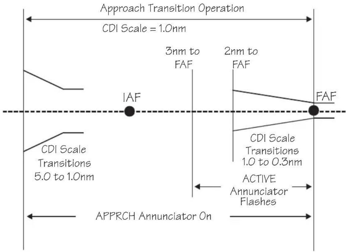
text_image
Approach Transition Operation CDI Scale = 1.0nm IAF 3nm to FAF 2nm to FAF FAF CDI Scale Transitions 5.0 to 1.0nm CDI Scale Transitions 1.0 to 0.3nm ACTIVE Annunciator Flashes APPRCH Annunciator OnApproach Transition Operation will usually be preceded by En Route Operations. Approach Transition will be preceded by Approach Active in the event of a missed approach or a canceled approach.
Note that there are two methods to enable an approach.
ENTER
Enable Approach - Method 1
Press ENTER when the “Enable Approach?” prompt is displayed as a message. The message will occur when an approach is loaded from the database and the aircraft is 30 nm or less from the destination airport. This message-prompt is repeated at 3 nm inbound to
the FAF if the approach has not yet been enabled. You will then get a message to enter the local altimeter setting.
Enable Approach - Method 2
When an approach has been loaded, the aircraft is less than 30 nm from the destination airport, and the approach has not yet been enabled, pressing FPL will result in the “Enable Approach?” prompt. If you press SEL while in Nav or Map mode home pages, the prompt will also appear. Press ENTER when this prompt is displayed to enable the approach. You will then get a message to enter the local altimeter setting.
At 30 nm from Destination Airport
- At 30 nm from the destination airport, the MSG annunciator will flash. Press MSG. The display will ask if you want to “Enable approach.” Press ENTER to enable the Approach operation. The Approach annunciator will light and the CDI sensitivity will automatically scale gradually from 5 nm to 1 nm full scale.
PRESS ENTER TO ENABLE APPROACH
- The display will verify that you have enabled the selected approach. You will now be prompted to enter the local altimeter setting. Turn the SMALL knob to change the barometric pressure values and turn the LARGE knob to move the cursor. Press ENTER.
MSG
ENTER
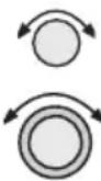
ENTER
MSG
- Press MSG to return to the Navigation function.
MSG
Initial Approach Fix (IAF)
- Prior to the Initial Approach Fix (IAF), the MSG indicator will light to announce a Waypoint Arrival Alert. Press MSG to acknowledge the message and view the instructions to the next approach point.
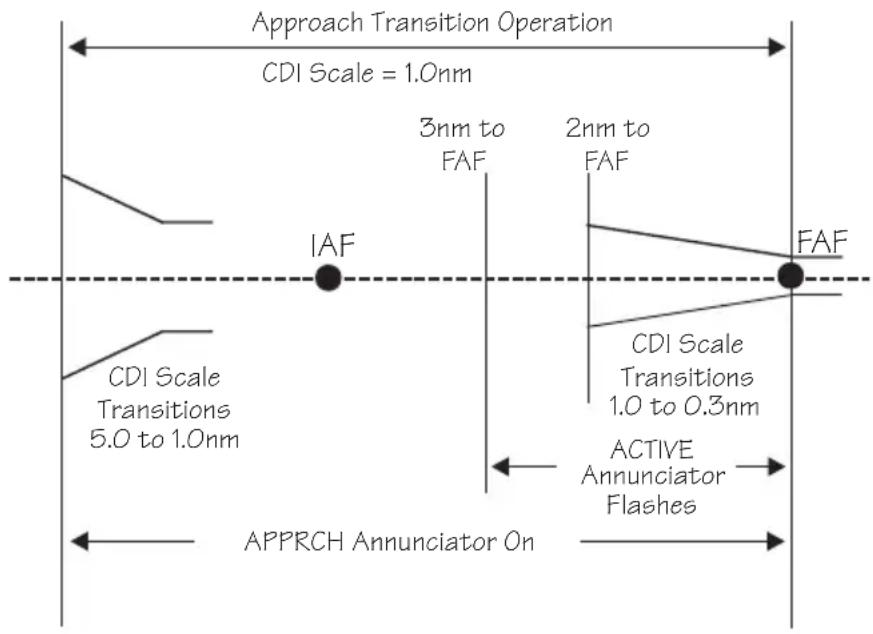
flowchart
graph TD
    A["Approach Transition Operation"] --> B["CDI Scale = 1.0nm"]
    B --> C["IAF"]
    C --> D["3nm to FAF"]
    D --> E["2nm to FAF"]
    E --> F["FAF"]
    G["CDI Scale Transitions 5.0 to 1.0nm"] --> H["ACTIVE Annunciator Flashes"]
    H --> I["FAF"]
    J["APPRCH Annunciator On"] --> K["FAF"]
    style A fill:#f9f,stroke:#333
    style G fill:#f9f,stroke:#333
    style J fill:#f9f,stroke:#333
MSG
WPT SEQ OBS/HLD
- Press MSG to return to the previous function.
- Prior to reaching the IAF, determine if a procedure turn or a course reversal is required. If so, press OBS/HLD to suspend sequencing. See page 21 for details on procedure turns.
Final Approach Fix (FAF)
- When you are 3 nm inbound to the Final Approach Fix (FAF) and not on Hold (sequencing suspended), the Active light will flash to indicate that you are about to transition to Approach Active and Approach RAIM Prediction will begin. At 2 nm from the FAF, the CDI sensitivity will start to gradually scale from 1.0 to 0.3 nm full scale. At the FAF, CDI sensitivity will be at 0.3 nm full scale.
MSG
- When you are near the Final Approach Fix, the MSG annunciator will flash and a standard Waypoint Arrival Alert will turn on. Press MSG to acknowledge the message. Press MSG to return to your previous function.
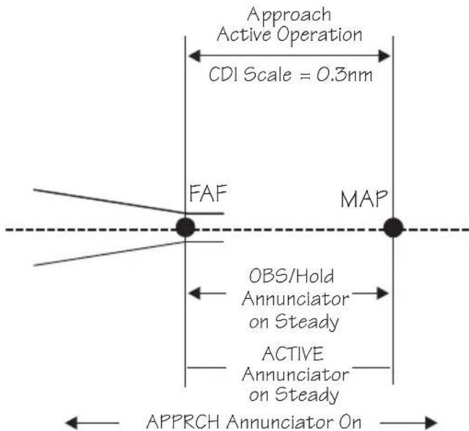
text_image
Approach Active Operation CDI Scale = 0.3nm FAF MAP OBS/Hold Annunciator on Steady ACTIVE Annunciator on Steady APPRCH Annunciator OnNOTE: If ACTIVE Annunciator is not Steady at FAF, do NOT Continue Approach
Before, At or After MAP, Press OBS/Hold for Missed Approach
Approach Active Operation
Approach Active Operation begins when you cross the Final Approach Fix (FAF) inbound if an approach has been loaded and enabled, the FAF is the active waypoint, and there are no system-detected reasons not to continue the approach (see Message Mode starting on page 8-1). The Approach Active annunciator is illuminated for Approach Active. The CDI sensitivity is 0.3 nm for approach active. Approach active is always preceded by Approach Transition.
As soon as you cross the FAF, the Approach Active annunciator will come on solid indicating that the Apollo GX is providing approach guidance. The active flight plan sequences and the Missed Approach Point (MAP) becomes the active waypoint. Sequencing is now automatically suspended and the OBS/HLD annunciator will be on.
Note
Anytime the Apollo GX is in Approach Active Operations, the approach may be canceled by pressing the OBS/HLD key.
Canceling the Approach will result in returning to Approach Transition operation. The Approach Active light will go out and the CDI will smoothly scale back to 1.0 nm sensitivity. Once Approach Active has been canceled by the pilot, it cannot be made active again except by again crossing the FAF inbound.
Note
Verify that the Approach Active annunciator illuminates at the FAF. If for any reason it is not on, do NOT continue the approach.

Crossing the Final Approach Fix
- You are now in Approach Active operation. The Approach Active annunciator will light continuously. If the Approach Active annunciator is not lighted continuously, do NOT continue the approach.
- The OBS/HOLD annunciator will light. Flight Plan leg sequencing is suspended with the MAP as the current TO waypoint.
Missed Approach Point (MAP)
- The MSG annunciator will indicate a standard Waypoint Alert as you approach the MAP. Press the MSG key to acknowledge the message. Press the MSG key to return to the previous function.
MSG
MSG
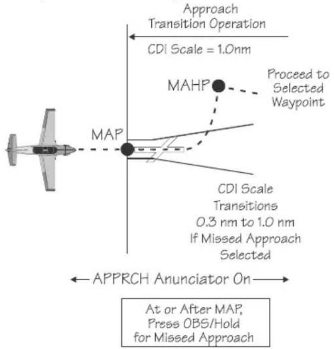
text_image
Approach Transition Operation CDI Scale = 1.0nm MAHP Proceed to Selected Waypoint MAP CDI Scale Transitions 0.3 nm to 1.0 nm If Missed Approach Selected APPRCH Anunciator On At or After MAP, Press OBS/Hold for Missed Approach- The OBS/HLD annunciator will remain lighted solid. CDI resolution is maintained at 0.3 nm. The To/From flag will switch from "TO" to "FROM" as you cross the MAP.
- If desired, and conditions allow, land the aircraft.
- If you do not choose to land, cancel the approach by pressing the OBS/HLD button. Follow the published missed approach instructions or clearance as appropriate. You will return to Approach Transition mode. The CDI resolution will gradually increase to 1.0 nm full scale deflection, the active annunciator will turn off, and the OBS/HOLD annunciator will turn off.
- Your Apollo GX will sequence to the next waypoint in the missed approach procedure (MAHP).
Missed Approaches
When you have reached the Missed Approach Point, you must either decide to land or not land. The Apollo GX will continue to provide guidance on an extension of your inbound course to the MAP. The MAP will remain the active waypoint, the TO/FROM flag will indicate FROM, and the Apollo GX will continue to display navigation data such as bearing and distance relative to the MAP.
If you have decided not to land, you will then follow either the published or alternate missed approach instructions. Missed approach instructions can be very complex. However, the Apollo GX can be used to provide guidance for virtually any missed approach.
The steps for a missed approach are as follows:
- Begin your missed approach. This usually includes a procedural clearance such as: “Fly runway heading to altitude,” or “climbing left turn to a heading of xxx.”
- Cancel the approach on your Apollo GX. Press OBS/HLD to enable sequencing and to cancel the


approach. You will now return to Approach Transition mode. The Approach Active light will go out and the CDI will gradually go back to Approach Transition CDI sensitivity (from 0.3 nm to 1.0 nm full-scale).
As soon as you enable sequencing, the Apollo GX will sequence to the next waypoint in the flight plan. This is the next waypoint in the published missed approach procedure.
If the next waypoint is the MAHP, it is an automatic holding point and sequencing will again be automatically suspended. The OBS/HOLD light will come back on. Operation will change from Approach Active to Approach Transition.
FPL


ENTER
- Verify or select the next waypoint in your flight plan. If the active waypoint is not the one you wish to navigate to, select a new active waypoint. If the active waypoint you want is already in your active flight plan, the easiest way to select it is to press FPL, to enter flight plan mode. Turn the SMALL knob until the waypoint you want is shown as the "TO" side of a flight plan leg. Then press DIRECT-TO and ENTER to select the waypoint.
Note
If the same waypoint appears in the approach sequence more than once, be sure to turn to the occurrence you wish to select.


- If a specific inbound course to the active waypoint is to be intercepted or flown, press DIRECT-TO twice.

ENTER
- Set the desired inbound course with the LARGE and SMALL knobs. If flying a holding pattern, press OBS/HLD. Then, press ENTER. Selecting an inbound course in this manner will suspend flight plan sequencing and the OBS/HLD annunciator will light. See page 9-24 for details on holding patterns.
OBS DTK: 151° TO ROARK IAF MAN BRC 356 DTK 356
WPT SEQ OBS/HLD
FPL
[Figure]
ENTER
ENTER
-
If you do not wish to hold or execute a procedure turn at the next waypoint, press OBS/HLD to enable sequencing at the active waypoint. You may also want to manually select a flight plan leg to intercept. In this case, press FPL, turn the SMALL knob to the desired leg and press ENTER. Press ENTER again to activate it.
-
After you have executed the missed approach, you may want to proceed to another destination or you may want to execute the same approach or another approach to the same airport.
Canceling An Approach
Whenever the Approach Active annunciator is lit, an approach may be terminated by a single action of the pilot. You may want to cancel an active approach to try the approach again, choose another approach, to proceed to another airport, or in response to an “Abort Approach” message. In any case, you must follow the appropriate missed approach instructions.
WPT SEQ OBS/HLD
- Press the OBS/HLD key to cancel the approach.
Canceling an approach does the following:
• Sequencing is enabled
- The unit returns to Approach Transition operations
• Approach Active annunciator turns off
• Approach annunciator remains turned on
• CDI scales to 1 nm full-scale deflection
• RAIM alarm limit goes from 0.3 nm to 1.0 nm. Though you have canceled the active approach, it is still loaded and enabled. You may activate a previous
Approach Basics (GX50/60)
leg or waypoint and navigate to try the approach again. Your flight plan remains unchanged.
Note
After an active approach has been canceled, you cannot immediately reactivate it. The approach can only be reactivated by crossing the FAF inbound, when the FAF is the active waypoint.

Repeating an Approach
You must cross the FAF inbound with the FAF selected as the active waypoint to allow reactivation of an approach. So, set up a course to return to the IAF and then back to the FAF.
FPL

- Press FPL. Turn the SMALL, inner knob to display the IAF as the TO waypoint.
MMV TO UBG 2x Q18 11.6MM ARPT IAF

ENTER
- Press DIRECT-TO and then ENTER to establish a direct course back to the IAF.
VOR UBG NEUERG FACIL OR USA


- Press the DIRECT-TO key twice to set a new Desired Track (DTK) to the selected waypoint. This also activates the OBS/HLD annunciator, so remember to press the OBS/HLD annunciator to enable waypoint sequencing when you have established your inbound course.


ENTER
Turn the SMALL knob to change the flashing value. Turn the LARGE knob to move the cursor. Press ENTER when finished. Press one of the mode keys (i.e. NAV, DB, FPL, or SYS) to quit without changing anything.

text_image
OBS DTK 159° UBG IAF AUTO BRC 159 DTK 159
Note
If you wish to intercept an approach leg, manually activate that leg. This is useful when receiving radar vectors back to intercept an approach leg. See “Manually Selecting a Flight Plan Leg” on page 9-19.
Selecting a Different Approach
After a missed approach, you may want to select one of the other approach choices for your intended destination airport.
FPL RPL

SEL

- Press FPL twice and then the SEL key. Turn the SMALL knob to display a flashing “Change Approach.” You may also reach this display from the Nav or Moving Map functions by pressing SEL.
ACTIVE: 82.5NM APPR ARPT: SLE CHANGE APPROACH?
- Press ENTER to change the approach. The approach choice will flash.
ENTER
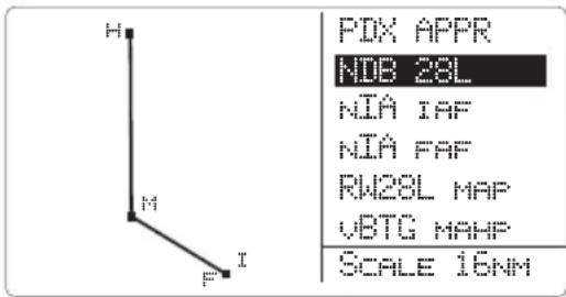
text_image
H M F I PDX APPR NDB 28L NIA IAF NIA FAF RW28L MAP VBTG MAHP SCALE 16NM
- Turn the SMALL knob to display the approach choices.

Note
If desired, press INFO to display a full list of the approach waypoints. Press INFO again to return to the select approach page.
ENTER
Press ENTER to choose the displayed approach.
Direct-To The Direct-To function is used for several purposes.
Especially during approach operations, you should be very comfortable with how this feature works. Review the Direct-To section on page 3-31 if you need a refresher before proceeding with approaches.
If you select a waypoint that is not one of the waypoints already in the active flight plan, use of Direct-To will automatically unload any active approach if you have crossed the IAF. Use of Direct-To also cancels parallel-track operations, if they are in use.
Direct-To Destination
Pressing DIRECT-TO once allows you to select a waypoint that you will navigate “Direct-To.” The first character will flash as the Apollo GX is ready for you to select a waypoint to fly “Direct-To.”
Direct-To OBS DTK
Pressing DIRECT-TO twice allows entry of a desired inbound course ① to the selected waypoint. The default is the current active TO waypoint, selection of another waypoint in your flight plan ②, and selecting automatic or manual sequencing ③.
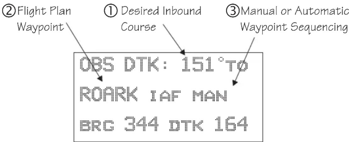
text_image
② Flight Plan Waypoint ① Desired Inbound Course ③ Manual or Automatic Waypoint Sequencing OBS DTK: 151°TO ROARK IAF MAN BRC 344 DTK 164Selection of automatic or manual sequencing is only available after an approach is enabled. Entering a desired inbound course to a waypoint automatically
suspends leg-sequencing at that waypoint and lights the OBS/HLD annunciator.
Subsequent pressing of DIRECT-TO toggles between the waypoint selection and OBS DTK choices.
Manually Selecting a Flight plan Leg
Approach operations often result in the need to manually select a leg of the active flight plan. Manual leg selection will often be required when operating with Radar vectors and there is the need to intercept an approach course. It may also occur when flying a DME-ARC to intercept an approach course. You cannot manually select a DME-ARC as a flight plan leg.
FPL

- Press FPL to reach the active leg of your flight plan. Then, turn the SMALL knob to display the desired leg.
LCD TO BKE
2xx 146° 28.2NM
ARPT IAF
- Press ENTER.
ENTER
LCD TO BKE
PRESS ENTER
TO ACTIVATE LED
- Press ENTER to accept the displayed destination waypoint. The unit will then go to NAV mode.
ENTER
Flight Plan Waypoint Sequencing
A flight plan will sequence to the next leg of the flight plan as the aircraft crosses to the bisector that runs through the “TO” waypoint. The bisector is defined as the angle that is half of the angle between the current leg and the next leg. When the unit is on Hold, or there is no next leg, the bisector is perpendicular to the inbound course to that waypoint. See the section about Holding Patterns on page 9-24 for more details on FROM/TO waypoints.

flowchart
graph TD
    A["Boeing"] --> B["Automatic waypoint sequencing when crossing these lines (bisector)"]
    B --> C["APPR"]
    C --> D["FAF"]
    D --> E["MAP"]
    style A fill:#f9f,stroke:#333
    style B fill:#ccf,stroke:#333
    style C fill:#cfc,stroke:#333
    style D fill:#fcc,stroke:#333
    style E fill:#ffc,stroke:#333
    note1["Automatic waypoint sequencing when crossing these lines (bisector)"]
    note2["X/2 = Y"]
    note3["Y"]
    note4["X"]
    note5["Y"]
    note6["Y"]
    note7["X/2 = Y"]
Note
If you manually select a leg that you have already passed, the Apollo GX will immediately sequence to the next leg.

In order to keep the Apollo GX from immediately sequencing when such a leg is selected, place your flight plan on hold by pressing the OBS/HLDkey prior to selecting the leg. It is then necessary to re-enable sequencing, by pressing the OBS/HLDkey again, when established inbound on the desired leg.
Procedure Turns
A procedure turn is a way of crossing the same waypoint more than once in order to accomplish a course reversal. First, make sure that flight plan leg sequencing is suspended. Second, after crossing the waypoint, set the correct inbound course to intercept. Finally, enable sequencing when you are established inbound.
Suspend Sequencing
When a procedure turn or course reversal is required, press OBS/HOLD to suspend sequencing. The OBS/HLD annunciator will light. In the cases shown in the diagram below, the Apollo GX will know when a course reversal is required and will automatically suspend sequencing.
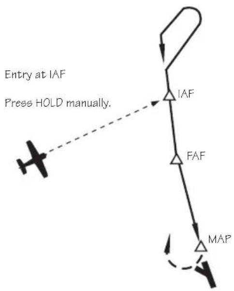
flowchart
graph TD
    A["Entry at IAF"] --> B["Press HOLD manually."]
    B --> C["IAF"]
    C --> D["FAF"]
    D --> E["MAP"]
    E --> C
    style A fill:#f9f,stroke:#333
    style B fill:#ccf,stroke:#333
    style C fill:#cfc,stroke:#333
    style D fill:#fcc,stroke:#333
    style E fill:#cff,stroke:#333
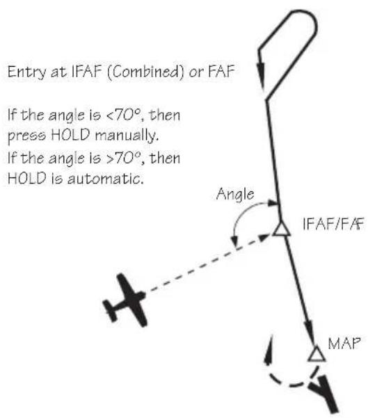
text_image
Entry at IFAF (Combined) or FAF If the angle is <70°, then press HOLD manually. If the angle is >70°, then HOLD is automatic. Angle IFAF/FAF MAPENTER
Set Inbound Course
- Upon crossing the waypoint you will be prompted to set the OBS course. Press ENTER to reach the OBS desired track page.
PRESS ENTER TO SET OBS COURSE: NAV/MAP TO EXIT
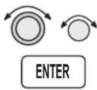
- Set the desired inbound course with the LARGE and SMALL knobs. Then, press ENTER.
text_image
OBS DTK: 000° TO BTG IFAF AUTO ERC 000 DTK 000- Verify that waypoint sequencing is set to "auto."
- Fly the procedure-turn or course reversal and intercept the selected inbound course.
Note
While flying outbound, the CDI is reverse sensing.

Many pilots are trained to set and fly the outbound course in course reversal form to eliminate reverse sensing of the CDI. In this case, when you are prompted to set the OBS course, enter the outbound course rather than the inbound course as described previously. During the procedure turn, press DIR-TO twice and then set the inbound course.
Enable Sequencing
As you intercept inbound course, the GX50/60 will automatically enable sequencing and notify you with a course intercept message when:
• The Track Angle Error is ≤45°
• Cross Track Deviation is ≤1 nm
Procedure Turn at FAF
A special condition occurs when a procedure turn is made at an IAF which is also the FAF. In this case, the Apollo GX50/60 will treat the waypoint as the IAF until sequencing is enabled when you are established inbound.
When you enable sequencing by pressing the OBS/HLD key (OBS/HLD annunciator light turns off), the IAF/FAF waypoint becomes the FAF. If you
are less than 2 nm from the FAF when you enable sequencing, then transition to Approach Active, i.e., the CDI sensitivity will begin changing to 0.3 nm full-scale deflection immediately. The approach annunciator will begin flashing immediately if all the conditions exist to allow the approach to go to the active condition (RAIM available, etc.). It is important for you to enable sequencing as soon after becoming established inbound as practical when you want the waypoint to become the FAF.
Note
Combined IAF/FAF waypoints are identified by the Apollo GX as IFAF waypoint types.


text_image
D 153° C 018° B E OED (IFAF) 146° MA14 (MAP) 337° A 157°Holding Patterns
A holding pattern is operationally the same as a procedure turn except that you usually intend to make repeated crossings of the waypoint on a specific inbound course. Like the procedure turn, the steps will always be:
• First, suspend sequencing
• Second, set the inbound course.
• Third, enable sequencing.

- Verify that sequencing is suspended, the OBS/HLD annunciator is lit prior to crossing the waypoint. Suspend sequencing by pressing the OBS/HLD key.
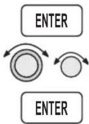
flowchart
graph TD
    A["ENTER"] --> B((Circular Arrow))
    B --> C["ENTER"]
    style A fill:#f9f,stroke:#333
    style C fill:#f9f,stroke:#333
-
After crossing the waypoint, establish the desired inbound course to the waypoint by pressing ENTER at the "Set OBS Course" message. Select the inbound course with the SMALL and LARGE knobs. Set waypoint sequencing to manual. Now, press ENTER.
-
Enter the holding pattern by the most appropriate entry method. For example, Direct, Teardrop, or Parallel, just as you would enter that holding pattern at a VOR. The following example shows holding at the Newburg VOR (UBG) with 020° inbound selected as the OBS course to UBG.

text_image
"TO" Side "FROM" Side HIO (NEXT) UBG (TO) O20 Perpendicular to O20 3S2 (FROM) If sequencing is enabled on the "TO" side of a line perpendicular to the destination waypoint, the flightplan will sequence to the "NEXT" waypoint when you cross the line. If sequencing is enabled on the "FROM" side of a line perpendicular to the inbound course at the active destination waypoint, the flightplan will sequence immediately to the "NEXT" waypoint.

- Finally, when you are ready to exit the holding pattern, press OBS/HLD.
Caution
While flying outbound, your CDI will provide reverse sensing.
Holding at the FAF
Holding at the FAF is different from other holding patterns. You must be inbound and have sequencing enabled to allow proper transition to Approach Active at the FAF.
This example shows holding at the FAF, SL (TURNO) for the NDB or GPS Runway 31 Salem (McNary) Airport (SLE).
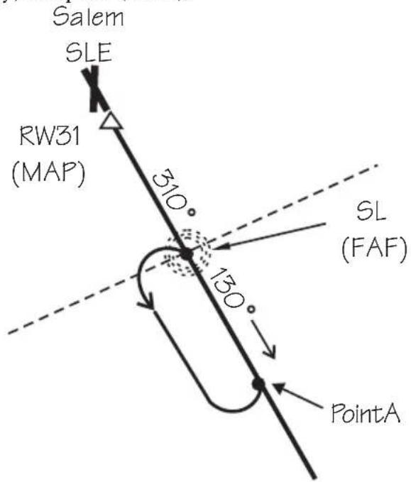
text_image
Salem SLE RW31 (MAP) 310° SL (FAF) 130° PointA
Press OBS/HLD to release the hold as soon as you intercept the inbound course (point A). This will allow you as much time as possible for transition to Approach Active operation. The waypoint SL (TURNO) becomes the FAF as soon as the hold is released.
DME Arcs (Arc Assist)
DME-Arcs are usually used as a method for pilots to intercept a flight plan leg, or a course to a fix. They are sometimes used as a method for reaching a subsequent fix such as a missed approach holding waypoint.
The Apollo GX automates your DME-Arc procedure. As you near the start of the DME-Arc rather than a typical arrival alert, you are prompted that the next leg is a DME-Arc and that you may use Arc Assist. Using Arc Assist is optional. Pressing ENTER will take you to the ARC reference point page. Verify that the reference waypoint is correct.
The CDI and map display can be used for guidance along the DME-Arc. You may also use the Arc Assist page for guidance to fly the arc.
- When you receive notice of the next leg or your flight plan is a DME-Arc, press ENTER.
- Verify the Reference waypoint is correct (if the reference is changed, the approach will be unloaded). Press ENTER.
ARC ASSIST REF: LMT VOR PRESS ENTER/SEL
- Verify the correct arc direction. You may select the Left or Right turning arc with the SMALL knob.
LEFT Arc DTK 031 REF: ILR VOR Rad 121° 131NMT
- Use the displayed information to fly the arc.

text_image
103380 3224 OED11 15 CF14 19.1ENTER
ENTER


Note
The desired track shown on an Arc Assist page is relative to the arc, not to the flight plan legs. The DME-Arc is always perpendicular to the present radial and it shows the desired track at the current radial if the aircraft was on the arc. It is the desired no-wind heading if established on the arc. If your distance from the reference waypoint is greater or less than the distance for the published arc, you will need to increase or decrease your heading to intercept the arc.
Vector to Final
The Vector to Final function allows you to fly directly to a final approach course.
When you select the Vector to Final option, sequencing is disabled and the OBS Direct To course is set automatically using the course defined by the FAF to MAP path with the FAF set as the TO waypoint. A course intercept alert will appear when: the Track Angle Error is ≤45^ , and the Cross Track Distance is ≤1 nm and on the TO side of the FAF. Sequencing is automatically enabled after intercepting the course and within 4 nm of the FAF.
SEL

ENTER
- While in the NAV or MAP functions, press SEL. You will see the flashing "Vector to Final?" prompt on the home page of the Flight Plan function. Turn the SMALL knob to show this display, if necessary. Press ENTER.
*ACTIVE* 41. ONM APPR ARPT: SLE VECTOR TO FINAL?
-
Follow ATC directives.
-
The Course Intercept alert will appear as you become established inbound on the final approach course.
COURSE INTERCEPT NEXT DTK 312°
Navigating to a DME
The Apollo GX may be used to help guide you to near the start of an ILS approach by using the location of a DME as a destination waypoint. The waypoint type is labeled “LOC-DME,” which stands for the Localizer-DME pair. Be careful when using this waypoint as the Localizer location and the DME location are often in separate locations. Your Apollo GX will use the DME location as the waypoint. Do NOT use the DME location as the start of the approach.
You may use the DME waypoint as a guide to the start of your approach and as a distance reference point for a step-down approach.
- Press DIRECT-TO. The Waypoint Type will flash. Turn the SMALL knob to select the "LOC-DME" waypoint type.
- Turn the LARGE knob clockwise one click. The first character of the LOC-DME Waypoint Name will flash. Turn the SMALL knob to select the desired character.
- Repeat step 2 until you have selected the LOC-DME. Press ENTER to navigate Direct-To the selected waypoint.
- Navigate to the DME waypoint according to Bearing and Distance.
- After reaching the waypoint, follow the directions of the appropriate approach plate for navigation.
RAIM RAIM stands for Receiver Autonomous Integrity
Monitor. It is a way a GPS receiver can verify when the signals it is receiving from one or more of the satellites are useable. It does this by using more satellites than are required for a position solution. In essence, the receiver compares the pseudo-ranges, or calculated distance measurements, from the satellites against what it expects. If this comparison yields too big a value, based on the current RAIM alarm limit, an Alarm is generated and you get a message telling you that a RAIM alarm has occurred.
It is important to understand that RAIM provides integrity, not accuracy. Accuracy is the ability of the GPS to determine a correct position with good satellite signals, enough satellites in view, and an acceptable geometric position of the available satellites. Integrity is the ability of the GPS system to detect when its position may not be accurate enough for IFR operations due to bad or false satellite information.
GPS systems limited to VFR use must meet the exact same accuracy requirements as those authorized for IFR use. Systems authorized for IFR use must also have an integrity monitor such as RAIM.
How Is RAIM Used?
TSO C129 calls for three different levels of RAIM protection: En Route, Terminal, and Approach. Plus, the receiver has the ability to predict RAIM availability at any given location and time.
Why Predict Availability?
Because RAIM requires that more satellites be used than are required for a position solution, RAIM may not always be available. The TSO requires that RAIM be available with a 0.3 nm. alarm limit, from a distance of 2 nm inbound to the Final Approach Fix (FAF) until the Missed Approach Point (MAP) is reached. A means must be provided to allow the pilot
to predict whether RAIM will be available at the estimated time of arrival at the destination. Your Apollo GX provides you with a RAIM prediction page. This page allows you to determine if RAIM should be available at any location and time. If it says RAIM will be available, it actually means that it will be available at your predicted time of arrival and plus and minus 15 minutes from your arrival time calculated at 5 minute intervals.
RAIM prediction is required to be done automatically by the equipment for the estimated time of arrival at the FAF and the MAP when you are 3 nm inbound to the FAF.
TSO C129 requires the RAIM alarm limit to be at least 2.0 nm for en route operations, 1.0 nm for Terminal operations, and 0.3 nm for Approach operations.
What are En Route, Terminal, and Approach Operations?
Approach RAIM, or 0.3 nm alarm limit, is provided from 2.0 nm inbound to the FAF until you cancel the Approach Active operation (usually at the MAP). Approach RAIM is provided only if an approach is loaded into your active flight plan and it is enabled.
Terminal RAIM, or 1.0 nm alarm limit is provided within 30 nm of your departure and your destination airport (except when Approach RAIM is provided). This is automatic and requires no pilot action. For those of you who are familiar with the traditional definition of Terminal, which was the ability to operate on SIDs and STARs that are only 4 nm wide, the term Terminal has been “redefined” in TSO C129 to mean within 30 nm of your departure or destination.
Approach Basics (GX50/60)
En Route RAIM, or a 2.0 nm alarm limit is provided at all other times.
Note that the three different equipment operation states: En route, Approach-Transition, and Approach-Active are somewhat but not directly related to the three RAIM alarm limits of En route, Terminal, and Approach. The equipment states are defined by the CDI sensitivity and operational requirements. When you depart an airport, the equipment is operating En route, but it is providing Terminal RAIM integrity.
How Often Will RAIM Be Unavailable?
RAIM availability depends on many factors, including the number of operational satellites in the sky, the time of day, the location, the receiver design, the antenna mask angle and location, and on the method of baro-aiding. The Apollo GX has been designed such that with an optimal 21 satellites in operation, Approach RAIM availability should exceed 95%. There are currently, at the time this manual was published, at least 24 satellites in operation; however, the Federal Navigation Radio Plan only guarantees that there is at least a 95% probability that 21 will be operational at any given time.
What Is Baro-aiding?
Baro-aiding is used to enhance RAIM availability. It is a method where pressure altitude data can be used to provide RAIM availability during some times when RAIM would not be available using the satellites alone.
What does it mean when I get a “RAIM not available” message?
If RAIM is not available, your Apollo GX may be capable of continuing to provide good accurate IFR navigation. What you have lost is the ability to tell if a satellite is sending bad data. For all operations except Approach, the FAA has determined that it is acceptable for you to continue to use GPS for IFR
navigation as long as you verify the accuracy of your position by other means at least every 15 minutes until RAIM becomes available again. This can be accomplished by cross-checking your GPS position against that of other navigation instruments. Even during times of no RAIM, if your Apollo GPS determines that it cannot provide an accurate position due to poor satellite availability or geometry, it will flag the navigation display as invalid. If the Apollo GX is providing valid navigation data, then it is still capable of providing good IFR navigation as long as the satellite data is good.
What Does A RAIM Alarm Mean?
A RAIM alarm means that the navigation data cannot be trusted to be within the alarm limit. A RAIM alarm means that the Apollo GX has determined that there is something wrong with the data it is receiving from one or more satellites. The data may be corrupted by a satellite failure, such as a clock failure, or it may have been corrupted by some form of signal interference. A RAIM alarm will also be accompanied by flagging all navigational displays as invalid. If you should ever see a RAIM alarm, do not trust the GPS position, and revert to other means of navigation as appropriate.
How Often Do Satellite Failures Occur?
There is not enough data to provide a good answer; however, it is known that they can and do happen. Satellite clock failures, one of the more probable failures, is more likely to occur on the older Block-I satellites, but this does not mean that it can't happen on the newer ones. When a satellite failure does happen, it can result in undetected error of miles in the position if a receiver is using the failed satellite in its navigation solution.
When a satellite fails, even if that failure is detected by an earth-based monitoring station, it can be some time before an uplink to that satellite can occur. During that time, there is no way for a GPS receiver to know that the information from that satellite is bad
directly from that satellite's transmissions. An integrity monitor, such as RAIM when it is available, protects you from false or misleading navigation displays resulting from bad satellite information.
RAIM Nav Page (GX50/60 Only)
The Apollo GX50/60 allows you to manage your RAIM prediction process, besides allowing for automatic prediction. You can manually predict RAIM for a selected waypoint at a given time and date. You may also manually exclude selected satellites for a given time and date.
Manual Prediction
The Apollo GX50/60 allows you to manually predict RAIM availability for any waypoint in the database for any selected date and time.
RAIM AVAILABLE AT: SLE ARPT 10Nov97 19:42 †
SEL
- In the NAV function, while viewing the RAIM prediction page, press SEL. The waypoint identifier line will flash.
RAIM AVAILABLE SELECT WAYPOINT? 10Nov97 19:42 †

- Turn the SMALL knob to choose between “Select Waypoint” and “Use DEST & ETA?”. The “Select Waypoint” choice allows you to select any waypoint in the database; use normal waypoint selection methods. The “Use DEST & ETA?” choice uses the currently selected destination waypoint and estimated time of arrival.
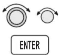
- Turn the LARGE knob to the date. Turn the SMALL knob to change a value. Turn the LARGE knob to move to the next value. Press ENTER when your choice is complete.
Approach Basics (GX50/60)
SEL
ENTER
- Press SEL. The "Predict RAIM?" choice will flash. Press ENTER to perform manual RAIM prediction now. The top line will display the result of the calculation of whether RAIM is available or not available.
Excluding Satellites
The Apollo GX50/60 allows you to specify satellite outages for RAIM predictions using information from NOTAMs or NANUs.

- While viewing the RAIM prediction page, turn the SMALL knob to the desired satellite (PRN).
PRNO1 TO IGNORE SAT PRESS SEL
SEL

- Press SEL. The hours out of service value will flash. Turn the SMALL knob to change a value. Turn the LARGE knob to move to the next value.

PRM01 OUT: 00HRS FR: 10Nov97 22:37 TO: 10Nov97 22:37
ENTER

- Press ENTER when your selection is complete. Turn the SMALL knob to the next satellite or back to the RAIM home page.
Clearing the Exclusion List
You can also easily clear the Exclusion List.
SEL

- While viewing the RAIM home page, press SEL. The “Predict RAIM?” choice will flash. Turn the SMALL knob to the “CLR Ignore List?” option.
CLR IGNORE LIST?
AT: SLE ARPT
10Nov97 22:06 +
ENTER
Emergency (Alternate) Approach
- Press ENTER to clear all satellite exclusions.
In the case of an emergency, alternate, or a sudden change in plans, you may need to select another airport for an approach landing. You will need to cancel the previous flight plan and then set a new course. The following three step method includes: 1) clear the current flight plan waypoints, 2) select and fly direct-to a nearest airport, and 3) load an approach for the nearest airport. This same procedure, except for the approach, can also be used for any waypoint type.
Clear Waypoints
- Press FPL twice to reach the Flight Plan home page.
FPL
FPL
ACTIVE: 50.2NM
DEST NPT: SLE
ACTIVE:
SEL

ENTER
- Press SEL and then turn the SMALL knob to reach the Clear Waypoints option. Press ENTER. The Message smart key will flash to note a message indicating that you do not have a TO waypoint.
¥HCTIVE: 50.2NM
DEST WPT: SLE
CLEAR WAYPOINTS?
Fly Direct-To a Nearest Airport
- Press the NRST key. Turn the SMALL knob to choose the nearest desired airport.
NRST

NEAR 1 TO PPOS CVO AIRPORT BRC 154° 5.4NM
D
ENTER
- Press DIRECT-TO. Press ENTER. You have now set a Direct-To course.
AIRPORT CVO CORNALLIS CITY OR USA
SEL
Set New Approach
- Press SEL. The Load Approach option will appear.
*ACTIVE* 0. ONM DEST WPT: CVO LOAD APPROACH?
ENTER

- Press ENTER. Now, turn the SMALL knob to choose the desired approach.
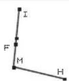
CVO APPR
GPS 17
INNOP IAF
ACYOL FAF
RN17 MAP
SHEED MAHP
SCALE 19NM
- Press ENTER. You
ENTER
have now set a new approach to the Nearest Airport.
Approach Examples
This section expands on the previous Approach Basics section. A variety of the situations that you may encounter while using approaches is included in this section. Use this section to familiarize yourself with the procedures that you expect to use in normal flight operations.
What you will see
• A description of the approach
- The examples will, in most cases, include an example Jeppesen and NOS chart of the approach
• A drawing of the approach details
• A description of the illustration points
• An illustration of the approach selection page
• Step by step directions explaining the approach
What you will do
- Set up a flight plan ending at the approach example airport with the appropriate name
- Read through the examples and follow along using the Apollo GX simulator
• Use the examples to learn about approach operations with the Apollo GX
Examples included in this section are:
• Straight in to Nampa, Idaho (Page 9-39)
• Holding at an IFAF in Medford, Oregon (Page 9-44)
• Missed Approach at Boise, Idaho (Page 9-51)
• VOR reference and missed approach at The Dalles, Oregon (Page 9-56)
• Manual flight plan leg selection (Page 9-61)
• DME Arc at Medford, Oregon (Page 9-26)
• Procedure turn at Medford, Oregon (Page 9-66)
• Procedure turn at Wenatchee, Washington (Page 9-68)
Approach Examples
Reproduced with permission of JeppesenSanderson Inc.
Reduced for illustrative purposes.

line
| Label | Value | | ----------------- | --------- | | NOFFE (IAF) | 12.3 | | PARMO | 115 | | EMTT (IAF) | 5600 | | Nozzle | 5600 | | NEWM | 5600 | | NEWM Industrial | 5600 | | NEWM Industrial | 5600 | | NEWM Industrial | 5600 | | NEWM Industrial | 5600 | | NEWM Industrial | 5600 | | NEWM Industrial | 5600 | | NEWM Industrial | 5600 | | NEWM Industrial | 5600 | | | NEWM Industrial | 5600 | | NEWM Industrial | 5600 | | NEWM Industrial | 5600 | | NEWM Industrial | 5600 | | NEWM Industrial | 5600 | | NEWM Industrial | 5600 | | NEWM Industrial | 5600 | | NEWM Industrial | 5800 | | NEWM Industrial | 5800 | | NEWM Industrial | 5800 | | NEWM Industrial | 5800 | | NEWM Industrial | 5800 | | NEWM Industrial | 5800 | | NEWM Industrial | 5800 | | NEWM Industrial | 5800 | | NEWM Industrial * 110° | 2.2 | | NEWM Industrial * 110° | 2.2 | | NEWM Industrial * 110° | 2.2 | | NEWM Industrial * 110° | 2.2 | | NEWM Industrial * 110° | 2.2 | | NEWM Industrial * 110° | 2.2 | | NEWM Industrial * 110° | 22 | | NEWM Industrial * 110° | 22 | | NEWM Industrial * 110° | 22 | | NEWM Industrial * 110° | 22 | | NEWM Industrial * 110° | 22 | | NEWM Industrial * 110° | 22 | | NEWM Industrial * 110° | 22 | | | NEWM Industrial * 110° | 22 | | NEWM Industrial * 110° | 22 | | NEWM Industrial * 110° | 22 | | NEWM Industrial * 110° | 22 | | NEWM Industrial * 110° | 22 | | NEWM Industrial * 110° | 22 | | NEWMIndustrial* | 2963 | | NEWMIndustrial* | 3088 | | NEMEW | NDZE | | NEMEW | TDZE | | PARMO | NDZE | | PARMO | TDZE | | PARMO | TDZE | | PARMO | TDZE | | PARMO | TDZE | | PARMO | TDZE | | PARMO | TDZE | | PARMO | TDZE | | PARMO | TDZE | | PARMO | TDZE | | PARMO | TDZE | | PARMO | TDZE | | PARMO | TDZE: NDZE: TDZE: NDZE: TDZE: NDZE: TDZE: NDZE: TDZE: NDZE: TDZE: NDZE: TDZE: NDZE: NDZE: NDZE: NDZE: NDZE: NDZE: NDZE: NDZE: NDZE: NDZE: NDZE: NDZE: NDZE: NDZE: NDZE: NDZE: NDZE: NDZE: NDZE: NDZE: NDZE: NDZE: NDZE: NDZE: NDZE: NDZE: NDZE: NDZE: NDZE: NDZE: NDZE: NDZE: NDZE: NDZe: NDZe: NDZe: NDZe: NDZe: NDZe: NDZe: NDZe: NDZe: NDZe: NDZe: NDZe: NDZe: NDZe: NDZe: NDZe: NDZe: NDZe: NDZe: NDZe: NDZe: NDZe: NDZe: NDZe: NDZe: NDZe: NDZe: NDZe: NDZe: NDZe: NDZe: NDZe: NDZe: NDZe : TDZE : TDZE : TDZE : TDZE : TDZE : TDZE : TDZE : TDZE : TDZE : TDZE : TDZE : TDZE : TDZE : TDZE : TDZE : TDZE : TDZE : TDZE : TDZE : TDZE : TDZE : TDZE : TDZE : TDZE : TDZE : TDZE : TDZE : TDZE : TDZE : TDZE : TDZE : TDZE : TDZE : TDZE / TDZE : TDZE : TDZE : TDZE : TDZE : TDZE : TDZE : TDZE : TDZE : TDZE : TDZE : TDZE : TDZE : TDZE : TDZE : TDZE : TDZE : TDZE : TDZE : TDZE : TDZE : TDZE : TDZE : TDZE : TDZE : TDZE : TDZE : TDZE : TDZE : TDZE : TDZE : TDZE : TDZE : TIDZE / TIDZE : TIDZE / TIDZE : TIDZE / TIDZE : TIDZE / TIDZE : TIDZE / TIDZE : TIDZE / TIDZE : TIDZE / TIDZE : TIDZE / TIDZE : TIDZE / TIDZE : TIDZE / TIDZE : TIDZE / TIDZES = TIDZE / TIDZE / TIDZE / TIDZE / TIDZE / TIDZE / TIDZE / TIDZE / TIDZE / TIDZE / TIDZE / TIDZE / TIDZE / TIDZE / TIDZE / TIDZE / TIDZE / TIDZE / TIDZE / TIDZE / TIDZE (Note: The values in the diagram correspond to the angles of the angle of the circle - the angle of the circle - the angle of the circle - the angle of the circle - the angle of the circle - the angle of the circle - the angle of the circle - the angle of the circle - the angle of the circle - the angle of the circle - the angle of the circle - the angle of the circle - the angle of the circle - the angle of the circle - the angle of the circle - the angle of the circle - the angle of the circle - the angle of each circle is equal to that value. The angle is calculated as a sum of all three degrees. The angle is calculated as a fraction of a circle. The maximum angle is 363°, minimum is 363°, and the circle is calculated as a square root of a circle. The maximum radius is 363°, minimum radius is 363°, and the circle is calculated as a square root of a circle. The maximum radius is 363°, minimum radius is 363°, and the circle is calculated as a square root of a circle. The maximum radius is 363°, minimum radius is 363°, and the circle is calculated as a square root of a circle. The maximum radius is 363°, minimum radius is 374°, minimum radius is 374°, and the circle is calculated as a square root of a circle. The maximum radius is 374°, minimum radius is 374°, and the circle is calculated as a square root of a circle. The maximum radius is 374°, minimum radius is 374°, and the circle is calculated as a square root of a circle. The maximum radius is 374°, minimum radius is 374°, and the circle is calculated as a square root of a circle. The maximum radius is 450°, minimum radius is 450°, and the circle is calculated as a square root of a circle. The maximum radius is 450°, minimum radius is 450°, and the circle is calculated as a square root of a circle. The maximum radius is 450°, minimum radius is 450°, and the circle is calculated as a square root of a circle. The maximum radius is 450°, minimum radius is 450°, and it's calculated as a square root of a circle. The maximum radius is 450°, minimum radius is 450°, and it's calculated as a square root of a circle. The maximum radius is 450°, minimum radius is 450°, and it's calculated as a square root of a circle. The maximum radius is 450°, minimum radius is 450°, and it's calculated as a square root of A circle (with labels 'MDA(H)' and 'MDA(H)' respectively). The maximum radius is calculated as a square root of A circle (with labels '90', '120', '140', '3040'(503')-1', '3040'(503')-1½', '3100'(563')-2'.CHANGES: New procedure.
© JEPPESEN SANDERSON, INC., 1997. ALL RIGHTS RESERVED.
Approach Example 1 - Straight In
This example illustrates the approach to Nampa, Idaho. This example was selected because it is a new approach designed especially for TSO C-129 GPS equipment. It is probably as simple an approach to fly with the Apollo GX as there is.
Note

It is good planning to always consider what you would do in the event of any equipment failures that may occur during flight operation, including your navigation system. Always make yourself aware of other available navaids should you need to select an alternate method of navigation.
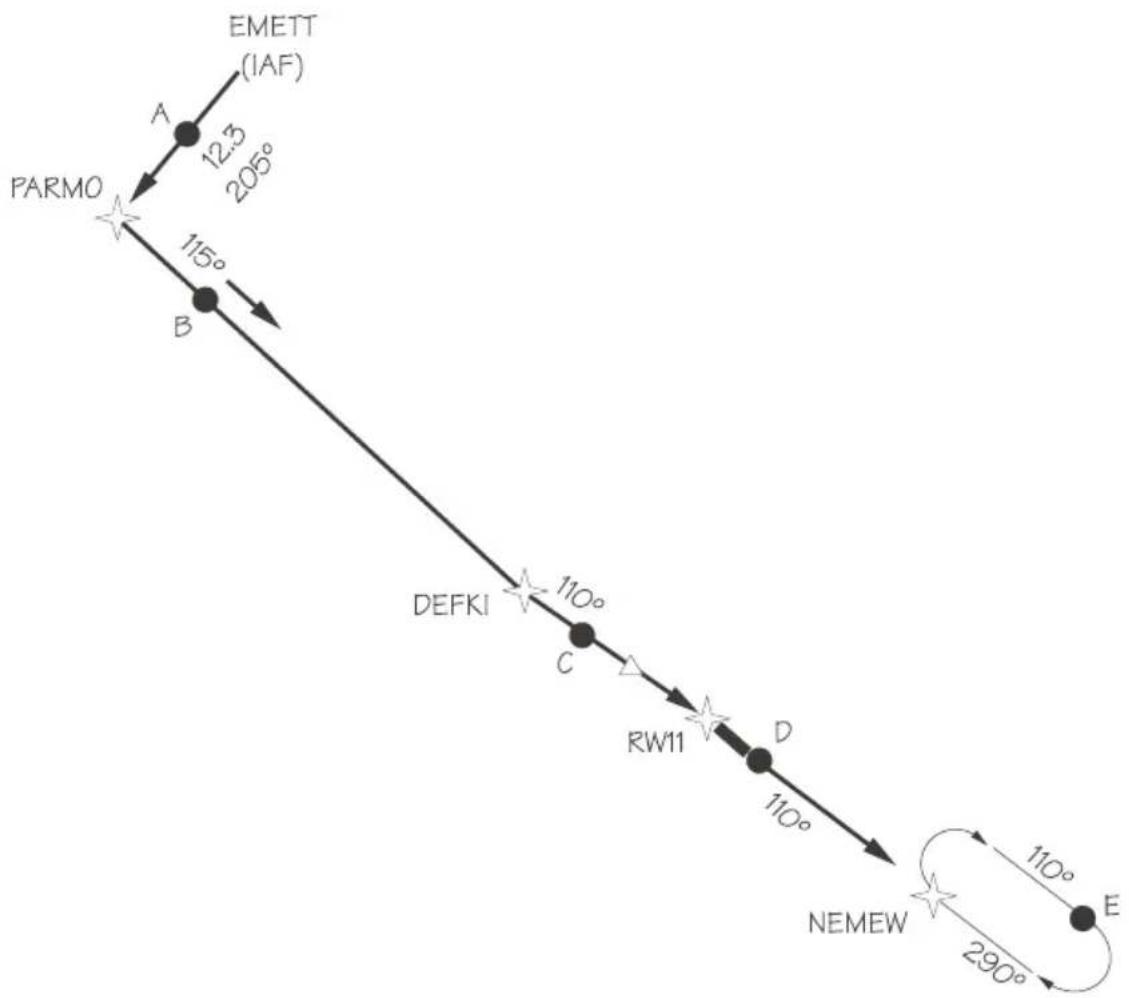
text_image
EMETT (IAF) A 12.3 205° PARMO B 115° DEFKI 110° C RW11 D 110° NEMEW 110° 290° EIllustration Points
A - Between EMETT (IAF) and PARMO (APPR)
B - Between PARMO (APPR) and DEFKI (FAF)
C - Between DEFKI (FAF) and RW11 (MAP)
D - Between RW11 (MAP) and NEMEW (MAHP)
E - In Holding Pattern
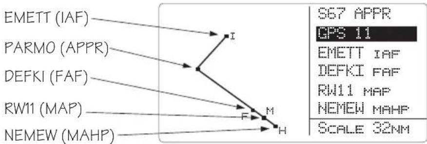
flowchart
graph TD
    A["EMETT (IAF)"] --> B["I"]
    C["PARMO (APPR)"] --> B
    D["DEFKI (FAF)"] --> B
    E["RW11 (MAP)"] --> F["F"]
    G["NEMEW (MAHP)"] --> H["H"]
    B --> F
    B --> H
    style A fill:#f9f,stroke:#333
    style C fill:#f9f,stroke:#333
    style D fill:#f9f,stroke:#333
    style E fill:#f9f,stroke:#333
    style G fill:#f9f,stroke:#333
    style B fill:#ccf,stroke:#333
    style F fill:#ccf,stroke:#333
    style H fill:#ccf,stroke:#333
    note right of B S67 APPR
        GPS 11
    end
En Route
Load and activate your flight plan, then load the approach. Select the Nampa Municipal GPS Rwy 11 approach.
30 nm From Nampa Municipal Airport
- The message annunciator will flash. Press MSG and then ENTER to enable the approach.
PRESS ENTER TO ENABLE APPROACH
MSG
ENTER

ENTER
NAV
- Select the local Altimeter Setting with the SMALL knob and then press ENTER. Press NAV to return to NAV mode.
Point A (Between EMETT and PARMO)
- Fly the segment.
- Verify that the Approach annunciator is on.
Point B (Between PARMO and DEFKI)
-
Fly the segment.
-
The Approach Active annunciator will begin flashing 3 nm from DEFKI (FAF) indicating that approach RAIM prediction is beginning. The transition to approach active is starting.
- At 2 nm from DEFKI the CDI scale will begin changing from 1 nm to 0.3 nm full scale deflection.
Point C (Between DEFKI and RW 11)
As you cross DEFKI, verify that the Approach Active and OBS/HLD annunciators are on steady.
Point D (Missed Approach)
- If you choose a Missed Approach at RW11, cancel the Approach Active operation by pressing the OBS/HLD key. The CDI sensitivity will now gradually scale back to Approach Transition sensitivity (1.0 nm full scale).
- NEMEW will become the TO waypoint. The inbound course to NEMEW is already the same as the approach inbound, so you do not need to enter it.
- NEMEW is the MAHP and will automatically become a holding waypoint. Verify that the OBS/HLD annunciator is lighted.
Point E (Holding Pattern)
- After crossing NEMEW, you will be prompted to set the OBS course. Turn the LARGE and SMALL knobs to select 290^ and press ENTER.

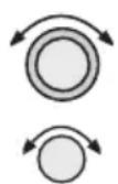
ENTER
OBS DTK: 290° TO NEMEN MAHP MAN BRC 315 DTK 315
- Fly the holding pattern. A parallel entry should work well.
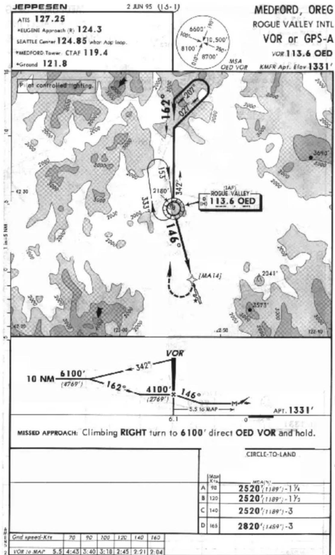
geo
| Metric | Value | |--------|-------| | A | 90 | | B | 120 | | C | 140 | | D | 165 | | Mean Kts | 90 | | MCA(%) | 2520' (1189') - 1¼ | | Mean Kts | 2520' (1189') - 1½ | | Mean Kts | 2520' (1189') - 3 | | Mean Kts | 2820' (1489') - 3 | | Gnd speed-Kts | 70 | | VOR to MAP | 5.5 | | P. at controlled lighting. | 162° | | 027° | 207° | | 155° | 342° | | 2180° | 333° | | 342° | 3690° | | 42.30 | 42.80 | | 42.50 | 42.00 | | 42.00 | 42.00 | | 42.00 | 42.00 | | 42.00 | 42.00 | | 42.00 | 42.00 | | 42.00 | 42.00 | | 42.00 | 42.00 | | 42.00 | 42.00 | | | 42.00 | 42.00 | | 42.00 | 42.00 | | 42.00 | 42.00 | | 42.00 | 42.00 | | 42.00 | 42.00 | | 42.00 | 42.00 | | 42.00 | 6100' (4769') | 342° | | 42.00 | 162° | 342° | | 42.00 | 4100' (2769') | 146° | | 6.1 | 6.1 | | 6.1 | 6.1 | | 6.1 | 6.1 | | 6.1 | 6.1 | | 6.1 | 6.1 | | 6.1 | 6.1 | | 6.1 | 6.1 | | 6.1 | 6.1 | | 6.1 | 6.1 | | 6.1 | 6.1 |CHANGES: Communications, airport name.
© JEFFESEN SANDERSON, INC., 1907, 1995. ALL RIGHTS RESERVED.
Approach Examples
Reproduced with permission of JeppesenSanderson Inc.
Reduced for illustrative purposes.
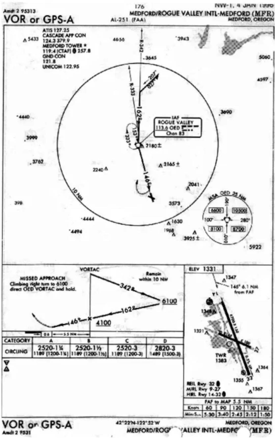
radar
| Location | Latitude (°) | | :--- | :--- | | ATIS 127.25 CASCADE APP CON 124.3 379.9 MEDFORD TOWER * 119.4 [CTAF] 257.8 GND CON 121.8 UNICOM 122.95 | 4656 | | IAF ROGUE VALLEY 113.6 OED Chan 83 | 3645 | | 3690 | 302 | | 2180± | 135 | | 2165± | 146 | | 2041 | 1630 | | 3573 | 1968 | | 3925± | 3925 | | 5922 | 5922 | | Category | A | B | C | D | | :--- | :--- | :--- | :--- | :--- | | CIRCUNG | 2520-1½ 1189 [1200-1½] | 2520-1½ 1189 [1200-1½] | 2520-3 1189 [1200-3] | 2820-3 1489 [1500-3] | | ▼ | — | — | — | — | | △ | — | — | — | — | ELEV 1331 ELEV: 1347 146° 6.1 NM from FAF TWR 1383 REIL Rwy 32 MIRL Rwy 9-27 HIRL Rwy 14-32 FAF to MAP 5.5 NM Knors: 60, 90, 120, 150, 180 Mim Sos: 5:30, 3:40, 2:45, 2:12, 1:50 NVW-1, 4 JAIN 1990 MEDFORD/ROGUE VALLEY INTL-MEDFORD (MFR) AL-251 (FAA) MEDFORD, OREGON MUSSED APPROACH Climbing right turn to 6100 direct OED VORTAC and hold. VORTAC Remain within 10 NM VORTAC Remain within 10 NM VORTAC Remain within 10 NM VORTAC Remain within 10 NM VORTAC Remain within 10 NM VORTAC Remain within 10 NM VORTAC Remain within 10 NM VORTAC Remain within 10 NM VORTAC Remain within 10 NM VORTAC Remain within 10 NM VORTAC Remain Within 10 NM VORTAC Remain Within 10 NM VORTAC Remain Within 10 NM VORTAC Remain Within 10 NM VORTAC Remain Within 10 NM VORTAC Remain Within 10 NM VORTAC Remain Within 10 NM VORTAC Remain Within 10 NM VORTAC Remain Within 10 NM VORTAC Remain Within UnOED VORTAC and hold. VORTAC Remain Within UnOED VORTAC and hold. VORTAC Remain Within UnOED VORTAC and hold. VORTAC Remain Within UnOED VORTAC and hold. VORTAC Remain Within UnOED VORTAC and hold. VORTAC Remain Within UnOED VORTAC and hold. VORTAC Remain Within UnOED VORTAC and hold. VORTAC Remain Within UnOED WIREY ALLEY INTL-MEDFC (MFR)Approach Example 2 - Holding at IFAF
This example uses an active flight plan ending at the Medford, Oregon airport (MFR). The last two waypoints in this example are the Klamath Falls, Oregon VOR (LMT) and the Medford airport. This approach example involves a procedure turn, a combined IAF and FAF (IFAF), and a MAHP holding pattern at the FAF. This example will include reflying the approach after being cleared from the holding pattern.
Illustration Points
A - Inbound to OED from the east
B - Outbound on the procedure turn
C - On the procedure turn
D - Inbound to OED
E - Between OED and MA14
F - Turning right and climbing to 6100 feet
G - Outbound from OED to enter the holding pattern
H - Inbound to OED in the holding pattern
The simulator does not replicate all procedures exactly. After you select a OBS DTK, the simulator will immediately place the aircraft location in line with the inbound course, bypassing a procedure turn or DME Arc.

text_image
207° D C 162° 027° G B 153° H 333° OED (IFAF) Rogue Valley E 146° MA14 F AEn route to Medford (MFR)
- Create a flight plan named "Example 2" with the last two waypoints as the Klamath Falls VOR (LMT) and the Medford airport (MFR).
- Activate the flight plan. Press FPL. Turn the LARGE knob to display the "Example 2" flight plan. Press SEL and then ENTER.
- Load the VOR or GPS-A approach to MFR. In Nav or Flight Plan modes, press SEL. The display will flash "Load Approach?" Press ENTER. Select "VOR A:OED" with the SMALL knob, if necessary, and press ENTER. Turn the SMALL knob to view the waypoint legs. Press NAV to view NAV info.
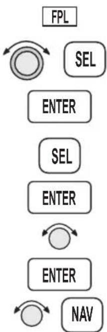
flowchart
graph TD
    A["FPL"] --> B["SEL"]
    B --> C["ENTER"]
    C --> D["SEL"]
    D --> E["ENTER"]
    E --> F["ENTER"]
    F --> G["NAV"]

text_image
vOED (IAF, FAF, & MAHP) MA14 (MAP) H I M MFR APPR VOR A vOED IAF vOED FAF MA14 MAP vOED MAHP SCALE 7NM30 nm from Medford (MFR)
- At 30 nm from your destination (MFR), the MSG annunciator will light. Press MSG. At the “Enable Approach” prompt, press ENTER.
MSG
ENTER
PRESS ENTER TO ENABLE APPROACH
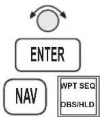
flowchart
graph TD
    A["ENTER"] --> B["NAV"]
    B --> C["WPT SEQ OBS/HLD"]
- The Altimeter Setting will flash. Turn the SMALL knob to display the local barometric pressure and press ENTER.
Point A (Inbound to OED from the east)
- Flight plan sequencing at OED is disabled because it is an IFAF in preparation for a procedure turn. The combined IAF/FAF waypoint is noted on your Apollo GX as IFAF.
- Verify that the Hold annunciator is ON.
Point B (Outbound on the procedure turn)
- After crossing OED, the To/From flag will indicate FROM. OED will remain the active waypoint.
- When prompted to enter the inbound course to OED, press ENTER. Turn the LARGE and SMALL knobs to display 162°. Press ENTER to activate the OBS course.
ENTER


ENTER
OBS DTK: 162° TO OED IFAF AUTO BRC 093 DTK 274
Note
Some pilots are trained to fly the procedure turn by first setting the outbound course. Then, once the procedure turn is started, set the inbound course. This method eliminates reverse sensing of the CDI.
With the Apollo GX, when you are prompted to set the OBS course, set it to 342^ , the outbound course. Once the procedure turn is started, press DIRECT-TO twice and set the inbound course to 162^ .

Point C (On the procedure turn)
Fly as you would with a VOR with “162° TO” selected on the OBS. Fly outbound via the 342 radial of OED to execute a procedure turn. Note that the CDI is now reverse-sensing. A distance of 2 to 3 nm outbound is recommended in order to allow adequate distance for the Apollo GX to transition to Approach Active as you pass the FAF inbound.
Point D (Inbound to OED)
- As you intercept the 162 inbound a course intercept alert is given. Sequencing is automatically enabled. Turn to intercept the desired course. At 3 nm inbound to OED, the Approach Active annunciator will begin flashing to indicate that approach RAIM prediction is beginning. The transition to approach active is starting.
- At 2 nm inbound to OED, the CDI sensitivity will begin changing from 1 nm to 0.3 nm full-scale deflection.
- As you cross OED, the Approach Active annunciator will come on solid to indicate that approach operation is active and you may continue the approach to the MAP (MA14).
Point E (Between OED and MA14)
- Continue to the missed approach point. Verify that the OBS/HLD and Approach Active annunciators are lighted steady.
- If you wish to cancel Approach Active, press OBS/HLD. Your Apollo GX will then revert to Approach Transition with 1 nm CDI deflection and a 1 nm RAIM alarm limit.
Point F (Choosing not to land at the MAP)
- At the Missed Approach Point, if you are not going to land, follow your missed approach clearance. The MAP will remain active and your Apollo GX will continue to provide guidance on the final approach course until you press the OBS/HLD key. The published missed approach instructions say “climbing right turn to 6100’ direct OED VOR and hold.” You will then press the OBS/HLD key as soon as you decide to miss the approach.
- The CDI will scale out to 1 nm and OED will become the active waypoint. As you reach 6100', press DIRECT-TO and then press ENTER to establish a direct route to the active waypoint (OED).


Approach Examples
- Because OED is the MAHP, it is automatically a Hold waypoint and flight plan sequencing is suspended. Verify that the OBS/HLD annunciator is lighted.
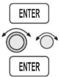
flowchart
graph TD
    A["ENTER"] --> B["Process Step 1"]
    B --> C["Process Step 2"]
    C --> D["ENTER"]
Point G (At the MAHP)
- Upon crossing OED, press ENTER when prompted to set the inbound holding course (153°). Use the LARGE and SMALL knobs to select 153°. Then, press ENTER.
OBS DTK: 153° TO OED MAHP MAN BRC 175 DTK 020
- After selecting 153^ inbound, enter the Holding pattern as you would for a VOR with 153^ selected on the OBS.
Point H (Inbound to OED in Hold Pattern)
-
Once cleared to reshoot the approach and you are established inbound in the holding pattern, fly Direct-To OED (the IFAF).
-
Press FPL twice (in the Map function, press SEL twice) to reach your active flight plan.
FPL FPL
[Non-Text]
- Turn the SMALL knob to reach the leg where OED (IFAF) is the TO waypoint.
LMT TO OED 134 274° 55.9NM ARPT IFAF
→ ENTER
- Press DIRECT-TO and then ENTER. Verify the OBS/HLD annunciator is illuminated. Return to the approach procedure beginning with point B.
Reproduced with permission of JeppesenSanderson Inc.
Reduced for illustrative purposes.

CHANGES: Control replication, GPS array data added.
© JAFFORD SANDERIN, NC., 1706, 1934. ALL RIGHTS RESERVED.

NDB RWY 10R
Andr 27 95201
43°34'N-118°13"W
MOISE, IDAHO
BOISE AIR TERMINAL (GOWEN FIELD) (BOI)
31
NW-1, 4 JAN 1995
Approach Example 3 - Missed Approach
This approach example describes an NDB approach from PARMO (IAF) to the Boise, Idaho airport (BOI). This example was chosen primarily because of the unusual published missed approach instructions and to illustrate how to navigate this missed approach with the Apollo GX.

text_image
PARMO (IAF) 097° 098° BO (FAF) (MAHP) USTIK A 278° E B RWIOR (MAP) C BOISE BOI 105° DIllustration Points
A - Between Parmo (IAF) and BO (FAF)
B - Between BO (FAF) and RW10R (MAP)
C - Just past RW10R (MAP)
D - Turn inbound to BO (MAHP)
E - Just past BO (MAHP)
En Route to BOI
-
Create a flight plan named "Example3" with the last two waypoints as the Ontario, Oregon airport (ONO) and the Boise, Idaho airport (BOI).
-
Activate the flight plan. Press FPL. Turn the LARGE knob to display the "Example3" flight plan. Press SEL and then ENTER.
FPL
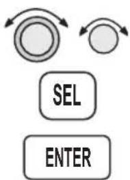
flowchart
graph TD
    A["Circle Node"] --> B["SEL"]
    C["Circle Node"] --> D["ENTER"]
*ACTIVE: 43.7NM DEST NPT: BOI ACTIVE
Approach Examples
SEL
ENTER

ENTER
- Load the NDB approach to BOI. In flight plan mode active plan or Nav mode home page, press SEL. The display will flash "Load Approach?" Press ENTER. Select "NDB 10R:PARMO" with the SMALL knob and press ENTER.

text_image
PARMO (IAF) nBO (FAF & MAHP) I H F M RW10R (MAP) BOI APPR NDB 10R PARMO IAF NEO FAF RW10R MAP NEO MAHP SCALE 47NMMSG
ENTER

ENTER
30 nm from Boise (BOI)
- At 30 nm from your destination, the MSG annunciator will light. Press MSG. At the “Enable Approach” prompt, press ENTER.
- Select the barometric pressure for the local altimeter setting with the SMALL knob and press ENTER.
Point A (Between PARMO IAF and BO FAF)
- The Approach Active annunciator will flash at 3 nm inbound. The CDI sensitivity begins to scale at 2 nm inbound.
- Verify that the Approach Active annunciator lights at BO. Verify that the OBS/HLD annunciator is lighted at BO.
Point B (Nearing MAP)
Fly the final approach and descend to MDA.
Point C (Missed Approach)
- When the decision has been made to execute the published missed approach, press OBS/HLD. The active waypoint will become BO (Missed Approach Hold Point). The CDI will gradually scale out to 1.0 nm full-scale deflection. The OBS/HLD annunciator, after turning off briefly, will turn back on as BO (now the Missed Approach Hold Point), is an automatic holding waypoint.
WPT SEQ OBS/HLD

ENTER
- Now press DIRECT-TO twice. Turn the LARGE knob to reach the reference waypoint. Turn the SMALL knob to select BO.
OBS DTK: 150° TO BO MAHP MAN BRC 162 DTK 162
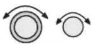
ENTER
- Turn the LARGE knob to select the OBS course. Select 105° with the SMALL knob as the desired inbound course. Press ENTER. The CDI will indicate FROM and will provide guidance on the 105° outbound bearing as per missed approach instructions. At 3900', begin the climbing right turn.
OBS DTK: 105° TO BO MAHP MAN BRC 162 DTK 162

ENTER
- When you reach 4200', or when your bearing to BO matches your current heading, press DIRECT-TO and then ENTER. This will establish a new inbound course direct to BO.
BO NDB JUSTIK (BOISE) FACIL ID USA
Point D (Inbound to BO)
Fly inbound on the new direct course to BO. The OBS/HLD annunciator will remain lighted.

ENTER
Point E (Missed Approach Hold Point)
As you pass BO, establish the new inbound holding course and enter the hold. When prompted, select an OBS DTK of 098^ with the LARGE and SMALL knobs. Press ENTER.

Note
Reshoot the approach following your missed approach, by reactivating the flight plan leg from PARMO (IAF) to BO (FAF) or select DIRECT-TO PARMO (IAF).
Approach Examples
Reproduced with permission of JeppesenSanderson Inc.
Reduced for illustrative purposes.
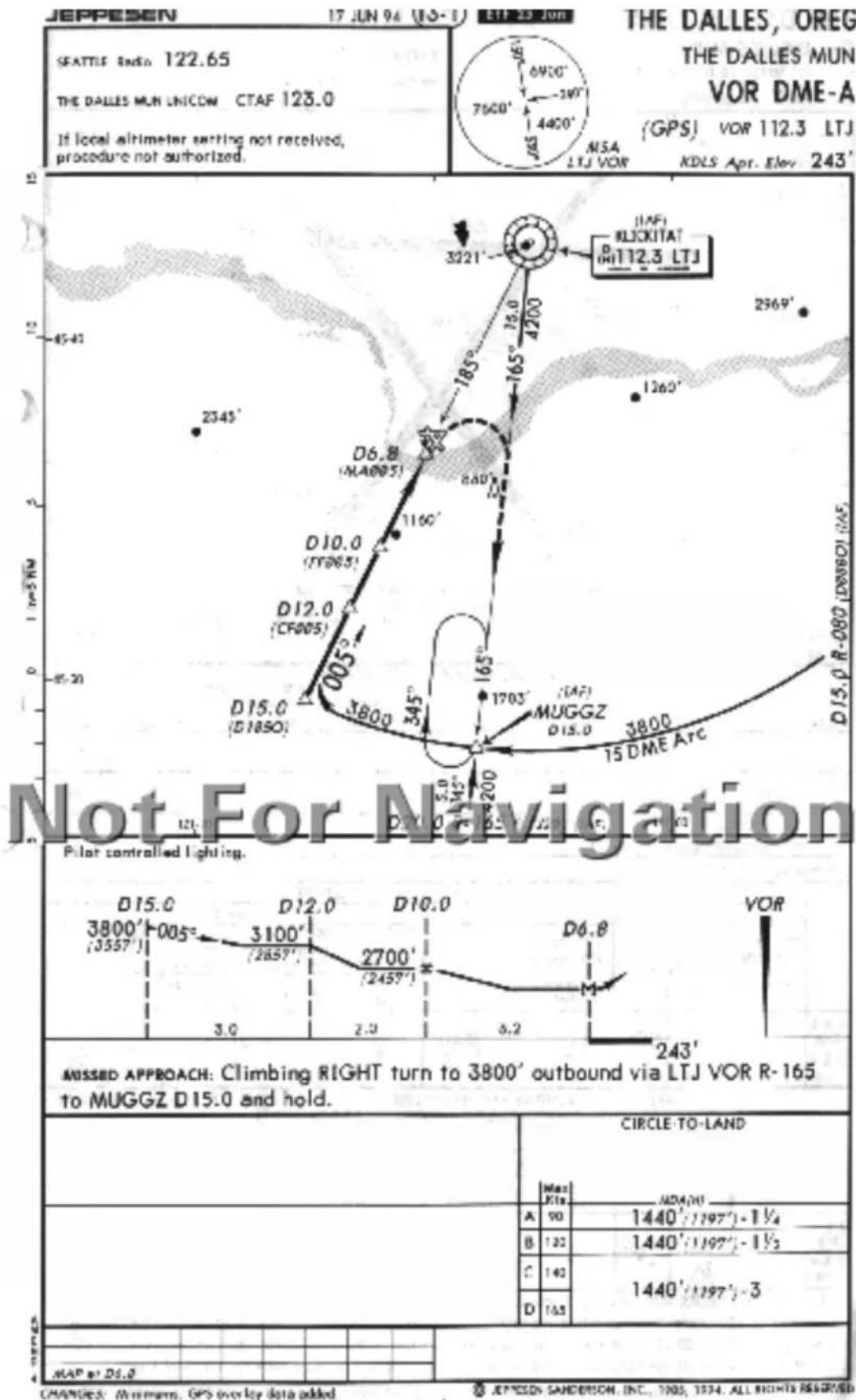

geo
Not For Navigation | Location | Station ID | Latitude (N) | Longitude (N) | Distance (±) | | :--- | :--- | :--- | :--- | :--- | | Seattle Radio | 112.3 LTJ | 2729 ± 0.1 | 2000 ± 0.1 | 2291 | | Seattle Radio | 112.3 LTJ | 2510 ± 0.1 | 2000 ± 0.1 | 3129 | | Seattle Radio | 112.3 LTJ | 2960 ± 0.1 | 2000 ± 0.1 | 2291 | | Seattle Radio | 112.3 LTJ | 4200 ± 0.1 | 2067 ± 0.1 | 2000 ± 0.1 | | Seattle Radio | 112.3 LTJ | 356 ± 0.1 | 2345 ± 0.1 | 2000 ± 0.1 | | Seattle Radio | 112.3 LTJ | 1060 ± 0.1 | 2000 ± 0.1 | 2000 ± 0.1 | | Seattle Radio | 112.3 LTJ | 1760 ± 0.1 | 2000 ± 0.1 | 2000 ± 0.1 | | Seattle Radio | 112.3 LTJ | 1680 ± 0.1 | 2000 ± 0.1 | 2000 ± 0.1 | | Seattle Radio | 112.3 LTJ | 830 ± 0.1 | 2000 ± 0.1 | 2000 ± 0.1 | | Seattle Radio | 112.3 LTJ | R-165 ± 0.1 | 2067 ± 0.1 | 2067 ± 0.1 | | Seattle Radio | 112.3 LTJ | R-165 ± 0.1 | 2345 ± 0.1 | 2345 ± 0.1 | | Seattle Radio | 112.3 LTJ | R-165 ± 0.1 | 2345 ± 0.1 | 2345 ± 0.1 | | Seattle Radio | 112.3 LTJ | R-165 ± 0.1 | 2345 ± 0.1 | 2345 ± 0.1 | | ... (Missing) / Missing Details | Station ID | Station Name | Latitude (N) | Longitude (N) | Distance (km) | | Various Stations or Locations | Category | A | B | C | D | | Various Stations or Locations | CIRCLING | 1440-1½ (1197 [1200-1½]) | 1440-1½ (1197 [1200-1½]) | 1440-3 (1197 [1200-3]) | - | | Various Stations or Locations | Location | Procedure Tum NA | Procedure Turn NA | Procedure Turn NA | Procedure Turn NA | | Various Stations or Locations | Category | A (LM) | B (LM) | C (LM) | D (LM) | | Various Stations or Locations | Category | B (LM) | C (LM) | D (LM) | | Various Stations or Locations | Category | D (LM) | E (LM) | F (LM) | | Various Stations or Locations | Location | REIL Rwy 30 (MRI) Rwy 12-30 Knots: 60, Min: Sec: 60, Knots: 90, Min: Sec: 90, Knots: 150, Min: Sec: 180, Knots: 60, Min: Sec: - | VOR/DME or GPS-A Andt: 4,94286 45'37"N-121"10"W 349 THE DALLES, OREGON THE DALLES MUNI (DLS) NW-1,4 JAN 1996 The DALLES MUNI (DLS) The DALLES MUNI (DLS) The DALLES MUNI (DLS) The DALLES MUNI (DLS) The DALLES MUNI (DLS) The DALLES MUNI (DLS) The DALLES MUNI (DLS) The DALLES MUNI (DLS) The DALLES MUNI (DLS) The DALLES MUNI (DLS) The DALLES MUNI (DLS)Approach Example 4 - VOR Reference
This example for the VORDME A:MUGGZ approach uses a flight plan with the last two waypoints as VOR IMB (Kimberly, Oregon) to The Dalles, Oregon (DLS). This example is illustrates the following points: the step down fixes are referenced to a VOR that is not co-located with the MAP, the nature of the published missed approach instructions, and a DME Arc is part of the approach.
Illustration Points
A - Approaching MUGGZ (IAF)
B - On the DME Arc between MUGGZ and D185O (ARC)
C - Inbound between D185O and CF005 (APPR)
D - Between CF005 and FF005 (FAF)
E - Between FF005 and MA005 (MAP)
F - Turning to intercept 165° to MUGGZ
G - Inbound to MUGGZ (MAHP)
H - In the holding pattern at MUGGZ
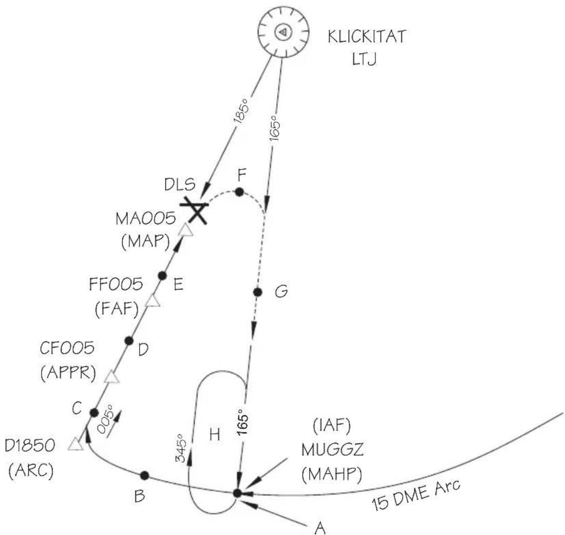
text_image
KLICKITAT LTJ 185° 165° DLS F MA005 (MAP) FF005 (FAF) E G CFO05 (APPR) D C 005° 345° H 165° (D1850 (ARC)) B (IAF) MUGGZ (MAHP) 15 DME Arc AEn Route
-
Create a flight plan named "Example4" with Kimberly VOR (IMB) as the last waypoint before The Dalles, Oregon (DLS) as the destination airport.
-
Activate the flight plan. Press FPL. Turn the LARGE knob to display the "Example4" flight plan. Press SEL, turn the SMALL knob to select "Activate," and then press ENTER.
EXAMPLE4 147NM DEST NPT: DLS ACTIVATE?
- Load the VOR DME A approach to DLS. In flight plan mode, press SEL. The display will flash "Load Approach?" Press ENTER. Select "VOR DME A:MUGGZ" with the SMALL knob and press ENTER.
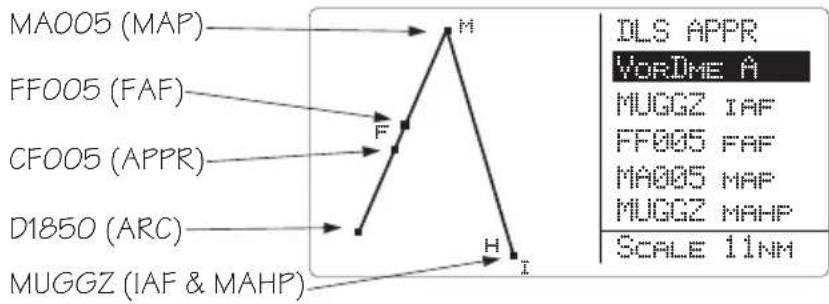
text_image
MA005 (MAP) FF005 (FAF) CFO05 (APPR) D1850 (ARC) MUGGZ (IAF & MAHP) M H I DLS APPR VORDME A MUGGZ IAF FF005 FAF MA005 MAP MUGGZ MAHP SCALE 11NMPoint A -Near MUGGZ (IAF)
- As you approach MUGGZ (the IAF), you will be prompted that a DME Arc is next. Press ENTER to reach the Arc Assist page.
ARRIVAL: NUGGZ DME NEXT-USE ARC AssIST? ENTER
FPL

SEL
ENTER
SEL
ENTER

ENTER
ENTER
ENTER
SEL
ENTER
- If the reference VOR is LTJ, press ENTER. If the reference is not LTJ, press SEL and select the LTJ VOR with the LARGE and SMALL knobs and then press ENTER. The Apollo GX will automatically provide guidance with the Arc Assist and Map pages.
HRC FSSIST
REF: LTJ WORK
10.000000 10.000000 11.000000 12.000000 13.000000 14.000000 15.000000 16.000000 17.000000 18.000000 19.000000 20.000000 21.000000 22.000000 23.000000 24.000000 25.000000 26.000000 27.000000 28.000000 29.000000 30.000000 31.000000 32.000000 33.000000 34.000000 35.000000 36.000000 37.000000 38.000000 39.000000 40.000000 41.000000 42.000000 43. 15 15 15 15 15 15 15 15 15 15 15 15 15 15 15 15 15 15 15 15 15 15 15 15 15 15 15 15 15 15 15

- Use the Arc Assist page as the primary guidance for flying the DME Arc. Select the Right Arc with the SMALL knob. You may also use the Map or Nav mode displays to navigate.
RIGHT ARC DTK 099
REF: LTG FOR
Rad 189° 17.8
Point B - On the arc between MUGGZ (IAF) and D1850 (ARC)
Use the Arc Assist page and your aircraft heading display to navigate to the selected inbound leg. The Desired Track (DTK) is your tangent to the arc on your present radial. For the right turn arc in this example, there are no other Arc waypoints to identify by radial and distance. If there were more waypoints, the Arc Assist page will continuously show the radial and distance from the Arc Reference making them easy to identify from your approach chart.
Point C - Inbound between D1850 (ARC) and CF005 (APPR)
- Flight plan sequencing will operate automatically for each of the remaining waypoints. You will receive arrival and next DTK messages as you cross each waypoint. Press MSG to view the message. Press MSG again to return to the previous display.
Point D - Between CF005 (APPR) to FF005 (FAF)
-
Note that the flight plan waypoints used as step-down fixes are depicted on the Jeppesen Approach Plate, but not on the NOS charts.
-
If you are using an NOS chart, you must identify the waypoints on the chart by looking at the distances between them on the vertical profile. You may want to view the Arc Assist page to show your distance relative to LJT.
-
As soon as FF005, the FAF becomes the active waypoint. The Approach Active light will begin flashing and the CDI will begin scaling to approach sensitivity, as you will be within 2 nm of the FAF when it becomes active.
-
As you cross FF005, verify that the Approach Active annunciator is lighted indicating that you may continue the approach.
Point E - Between FF005 (FAF) and MA005 (MAP)
-
Continue to the Missed Approach Point (MA005).
-
Verify that the OBS/HLD and Approach Active annunciators are lighted. Flight plan waypoint sequencing will be placed on hold.

Point F - Turning to intercept 165° to MUGGZ (MAHP)
- When you reach the Missed Approach Point and you wish to fly the published Missed Approach procedure, press OBS/HLD to reactivate waypoint sequencing as you start your climbing right turn.

flowchart
graph TD
    A["D"] --> B["Circle"]
    C["D"] --> D["Circle"]
    E["ENTER"] --> F["Arrow Up"]
    E --> G["Arrow Down"]
- Press DIRECT-TO twice and set the outbound course to 165^ . Turn the LARGE and SMALL knobs to select 165^ and then press ENTER.
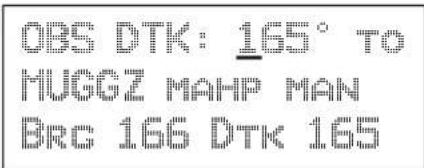
text_image
OBS DTK: 165° TO HUGGZ MAHP MAN BRC 166 DTK 165Point G - Inbound to MUGGZ (MAHP)
The CDI will scale back to Approach Transition CDI sensitivity. The MAHP (MUGGZ) will become the active waypoint. Use the CDI to intercept the course.
Point H - Holding Pattern
Fly the holding pattern.
Reshoot the Approach
If you are going to reshoot the approach from a hold at the IAF, select MUGGZ as the IAF in your approach sequence again.

- While holding at MUGGZ (MAHP), press FPL, turn to the leg IMB (VOR)-to-MUGGZ (IAF) with the SMALL knob.

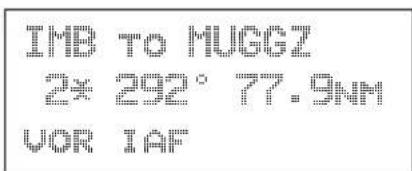
text_image
IMB TO HUGGZ 2¥ 292° 77.9NM VOR IAF
- Press DIRECT-TO and then ENTER. Your flight plan will now continue to the next appropriate waypoints.
ENTER
Manual Flight Plan Leg Selection Example
You are flying a section of an active flight plan from SLE to BTG to OLM. As you approach the Portland area, you are given Radar vectors to the West of your course. ATC then tells you: "Fly heading 360, resume own navigation, intercept V287 to OLM, then as filed..."

flowchart
graph TD
    A["OLYMPIA"] --> B["V287"]
    B --> C["CDI indicates - Fly direct on V287"]
    C --> D["BATTLE GROUND"]
    D --> E["Original desired flight plan"]
    F["SALEM"] --> G["TURNO"]
    H["V231"] --> I["Vectored course"]
    J["CDI indicates - Fly right to intercept V287"] --> K["Vectored course"]
    L["Vectored course"] --> M["Vectored course"]
Approach Examples
Manually select the leg from BTG to OLM (which is V287). Even though you have not yet reached BTG, you will know when you have intercepted this course.

- Press FPL twice to reach the active plan in Flight Plan Mode. This example uses a flight plan from the Salem (SLE) airport to the Battle Ground (BTG) VOR and then to the Olympia (OLM) VOR. Turn the SMALL knob clockwise one click to view the first leg of your flight plan.
Note that on the second line of each leg page, a number appears to indicate the leg number. An Asterisk is used after the number of each leg to indicate the active flight plan.
SLE TO BTG
130001°53.2NM
ARPT VOR
Two asterisks after the leg number indicate the active leg of the active flight plan (SLE to BTG).
BTC TO OLM
2* 331° 74.4NM
VOR VOR

-
Turn the SMALL knob until the leg you wish to activate is shown and then press ENTER twice.
-
Now fly the ATC assigned heading of 360 until the CDI centers to indicate that we have intercepted V287.
Approach Example 5 - DME Arc
The following example describes the process for intercepting and flying a DME-Arc. This example uses a flight plan from Klamath Falls (LMT) to Medford (MFR) and will navigate along the VOR DME Runway 14 approach. You may also use Ashland (S03) to make your flight a little quicker.
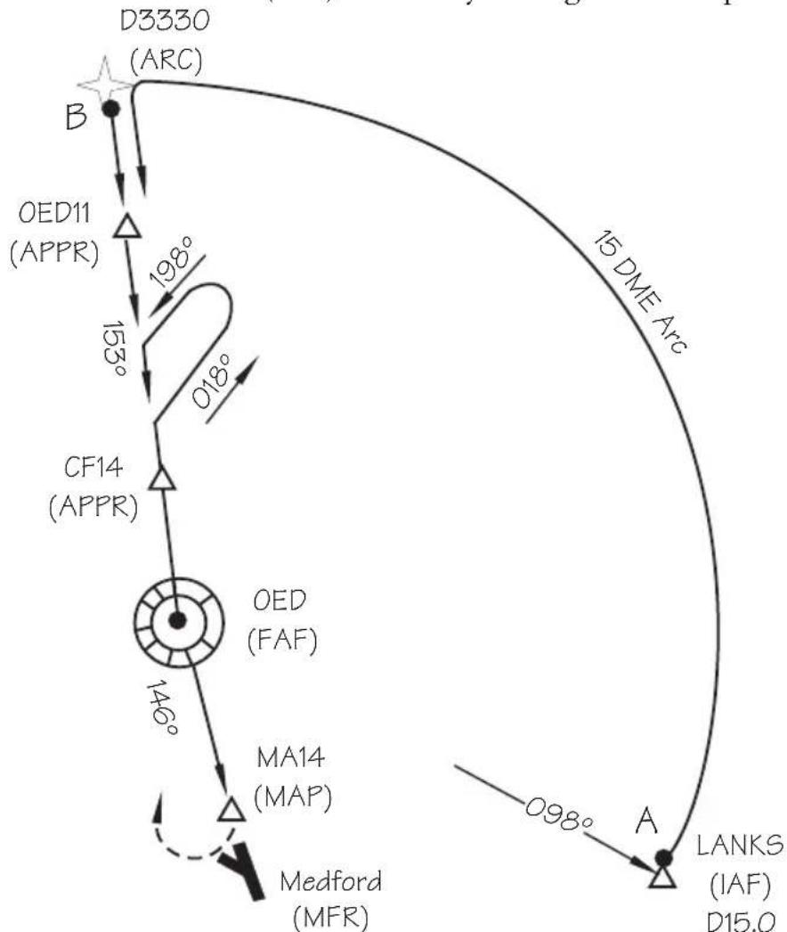
text_image
D3330 (ARC) B OED11 (APPR) 198° 153° CF14 (APPR) 146° OED (FAF) MA14 (MAP) Medford (MFR) 15 DME Arc 018° A LANKS (IAF) D15.0- Create a flight plan from Klamath Falls, Oregon to Medford, Oregon. Activate the flight plan and then load an approach. Select the VOR DME 14: LANKS approach. The main approach waypoints are shown in the list; intermediate points are not.

text_image
D3330 (ARC) OED11 (APPR) CF14 (APPR) OED (FAF) (MAHP) MA14 (MAP) MFR APPR WORDME 14 LANKS IAF VOED FAF MA14 MAP VOED MAHF SCALE 29NM LANKS (IAF)Approach Examples


- Some approaches use additional intermediate waypoints not listed on the approach selection page, but are shown as small squares. Press INFO to view all waypoints in the approach. Turn the SMALL knob as necessary to view additional waypoints. Press INFO again to return to the previous page.

text_image
LANKS → D3330 → OED11 → CF14 → OED → MA14 →ENTER
- At about 18 nm from LANKS you will prompted to enable your approach. Press ENTER to enable it and then enter the local altimeter setting. In NAV Mode view the home NAV page and watch your progress to the first waypoint (LANKS).
MSG
Point A (LANKS to D3330)
- When you arrive at LANKS, the MSG key will flash. Press MSG to view the message. Press ENTER.
ENTER

text_image
ARRIVAL: LANKS DME NEXT-USE ARC ASSIST? ENTERENTER
- You will be advised to use the Arc Assist page in NAV mode. Verify the proper reference waypoint (OED in this case). Press ENTER to automatically select the DME Arc.

text_image
ARC ASSIST REF: OED VOR PRESS ENTER/SELSEL

The Arc Assist page will now be displayed. If the displayed default reference is not the desired one for the DME Arc, press SEL and use the LARGE and SMALL knobs to select the correct reference waypoint and the Left Arc. Use this page and your aircraft heading to fly the arc.

text_image
LEFT ARC DTK 245 REF: OED VOR RAD 335° 16.4NMT- Follow the Moving Map or Arc Assist page information to fly the arc.
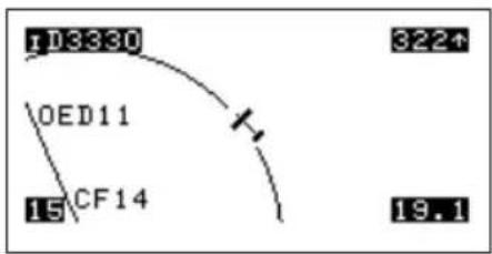
text_image
103380 322↑ OED11 CF14 15 19.1- Flight plan waypoint sequencing will operate normally.
Note
When intercepting and flying DME-ARCs, autopilots may be used only in the heading mode. Autopilots may be used in Nav mode if you manually update the course bug. Autopilots may be used to capture the course you select to intercept.
OED11 to CF14 to OED to MA14
Flight plan sequencing will operate automatically. You will receive arrival messages as you cross each waypoint. Press MSG to view the message. Press MSG again to return to the previous display.
MA14 (MAP) and OED (MAHP)
-
When you reach the MAP, waypoint sequencing will be suspended. Land the aircraft.
-
If you need to perform a missed approach, press OBS/HLD to cancel approach active operation. OED will become the TO waypoint. Fly to the MAHP (OED). The MAHP is an automatic holding waypoint. Verify that the OBS/HLD annunciator is lighted.


Approach Example 6 - Procedure Turn 1
This example uses a flight plan from Roseburg, OR (5S1) to Medford, OR (MFR) to demonstrate how to recover when you overshoot the point where you need to place sequencing on hold (Point B). If you cross an IAF without suspending sequencing (pressing OBS/HLD), the Apollo GX will automatically sequence to show MA14 as the next TO waypoint. However, for this approach you must perform a procedure turn first. You must then reset your course to take you through the procedure turn. Reset the course for the procedure turn by selecting OED as the reference waypoint for an OBS DTK course of 153°. The example also illustrates a procedure turn when the IAF and FAF use the same point (IFAF). The example uses the VOR DME 14: OED approach.
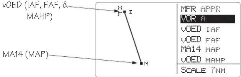
text_image
VOED (IAF, FAF, & MAHP) MA14 (MAP) H I M MFR APPR VOR A VOED IAF VOED FAF MA14 MAP VOED MAHP SCALE 7NMIllustration Points
Point A - Entry into the approach.
Point B - Cross OED (IAF) and head outbound.
Point C - Make procedure turn.
Point D - Course intercept.
Point E - Approach active.
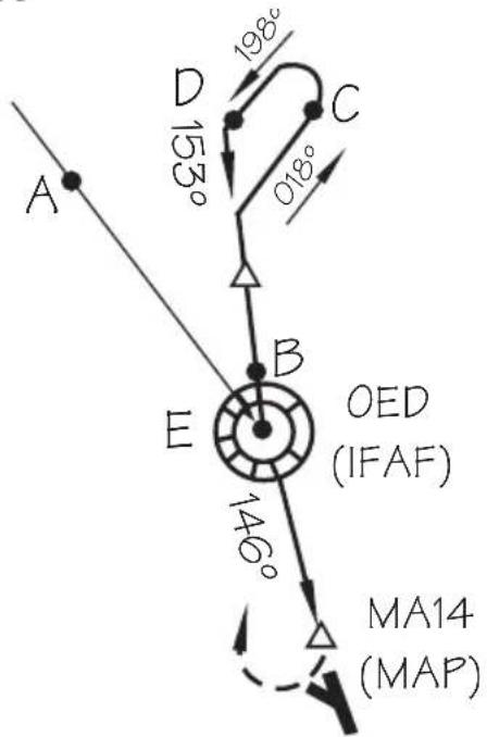
text_image
A D 153° C 198° 018° B E OED (IFAF) 146° MA14 (MAP)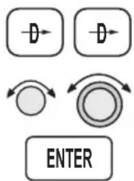
flowchart
graph TD
    A["D"] --> B["ENTER"]
    C["D"] --> D["ENTER"]
    E["Circle"] --> F["Arrow to Center"]
    G["Arrow to Center"] --> H["Arrow to Center"]
- Point A - At 30 nm west of the MFR airport, you will be prompted to “Enable Approach.” As the current Track Angle is less than 70^ to the FAF-MAP leg, sequencing is not suspended.
- As you cross over the OED VOR (IAF) at point E, the unit will sequence to MA14, because sequencing was not suspended prior to OED.
- If you still need to fly the procedure turn to lose altitude, set the OBS course for the inbound course. Press DIRECT-TO twice to reach the OBS page. Use the SMALL and LARGE knobs to select 153° and select OED (IFAF) as the reference waypoint. Verify that waypoint sequencing is set to “auto.” Press ENTER to establish an inbound course. Note that your CDI will “reverse-sense” while outbound, just like a VOR with 153°-TO selected on the OBS. Also, the TO/FROM flag will change to TO.
- Point C, shows the procedure turn.
- At point D, you will receive a course intercept alert. Sequencing will be automatically enabled. OED becomes the FAF and the Apollo GX will transition to Approach Active at OED.
- At point E, the Apollo GX will be in Approach Active operation.
Approach Example 7 - Procedure Turn 2
For this example, use the VOR or GPS-B approach for Wenatchee, Washington. You will start the approach using the CASHS transition. The example involves a procedure turn at the FAF that is not also the IAF.
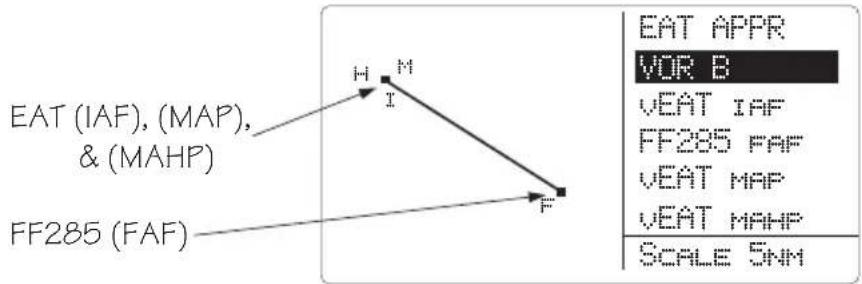
text_image
EAT (IAF), (MAP), & (MAHP) FF285 (FAF) H M I F EAT APPR VOR B VEAT IAF FF285 FAF VEAT MAP VEAT MAHP SCALE 5NMIllustration Points
Point A - Between CASHS and EAT.
Point B - A heading of 105^ between EAT and FF285.
Point C - Continue on a heading of 105^ between
FF285 and the procedure turn until beyond FF285.
Point D - Make the procedure turn.
Point E - Intercept the 285^ inbound to FF285.
Wenatchee
EAT
(IAF)
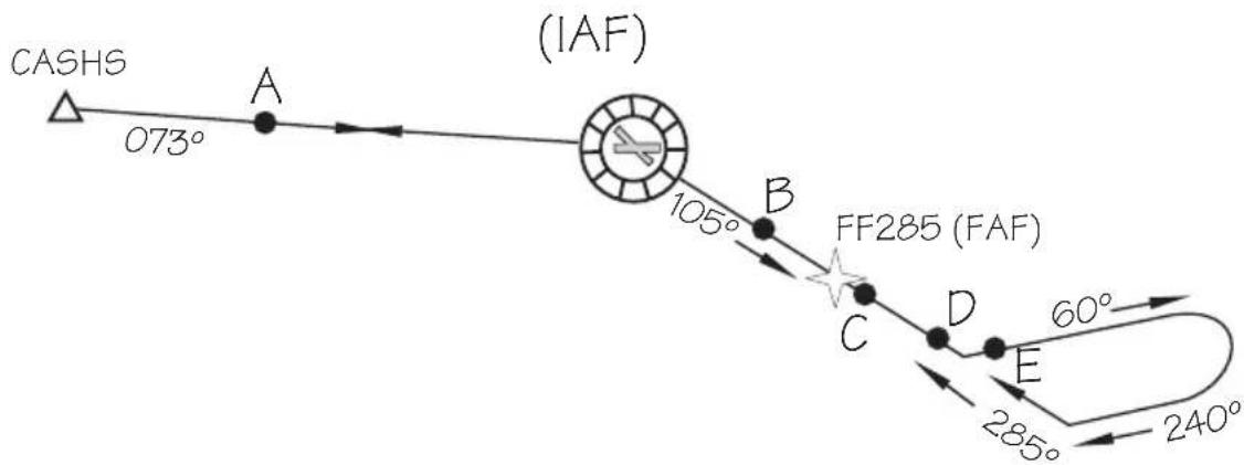
text_image
CASHS 073° A (IAF) 105° B FF285 (FAF) C D E 60° 285° 240°-
Point A - A heading of 073^ inbound to EAT.
-
Point B - The Apollo GX will anticipate the procedure turn and automatically suspends sequencing. Verify that the OBS/HLD annunciator is illuminated.
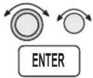
- Point C - You will be prompted to enter the OBS DTK when you near the FAF. Select an OBS setting of 285^ with the LARGE and SMALL knobs and then press ENTER to select an inbound course. Note that the CDI will be “reverse-sensing” just as it would when outbound from a VOR with the OBS set to the inbound course.
- Point D - Make the procedure turn.
- Point E - At the intercept of the inbound course to the FAF you will receive a course intercept message and sequencing will be automatically enabled.
Using the LOC-DME Waypoint
The Apollo GPS may be used to identify waypoints that require DME distance information on an instrument approach by using the LOC-DME as a destination waypoint. The waypoint type is labeled “LOC-DME,” which stands for the Localizer-DME pair. Be careful when using this waypoint as the Localizer location and the DME location are often in separate locations. Also, the accuracy of the position of the DME waypoint depends on the accuracy of the information provided in the database. Your Apollo GPS will use the DME location as the waypoint. Do NOT use the DME location for course guidance. You cannot activate an approach to a LOC-DME waypoint, because it is not an airport.
You may use the LOC-DME waypoint as a guide to identify DME-defined points on your approach and as a distance reference point for a step-down approach. The distance value will be accurate, but the internal CDI will point to the DME antenna location, not necessarily the runway centerline. Use your Nav receiver for Localizer and Glideslope course guidance. Use your Apollo GPS for distance information to supplement your DME.
The LOC-DME will appear in its own category when you perform the emergency search function.
Approach Examples
The following examples of typical approaches illustrate where the LOC-DME waypoint may be useful. In addition, examples using DME information from VOR waypoints are given.
ILS with DME Data from ILS DME Antenna
The following example uses the ILS Rwy 10L approach to Portland International airport. This procedure describes the use of your Apollo GPS distance display to supplement the DME distance as you reach the BUXOM intersection.
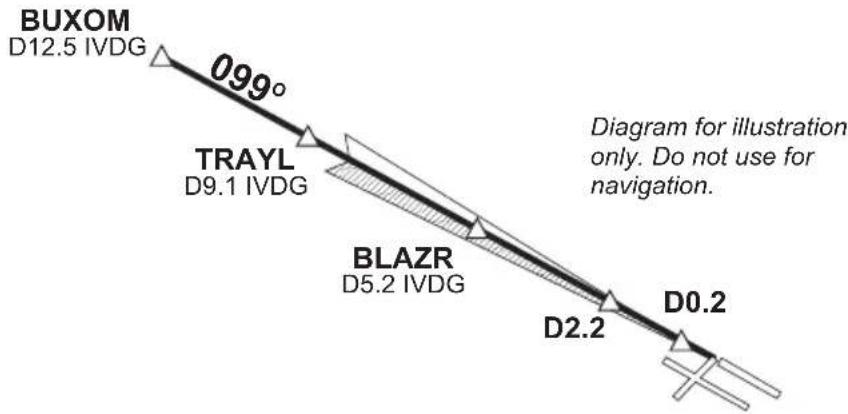
text_image
BUXOM D12.5 IVDG 099° TRAYL D9.1 IVDG BLAZR D5.2 IVDG D2.2 D0.2 Diagram for illustration only. Do not use for navigation.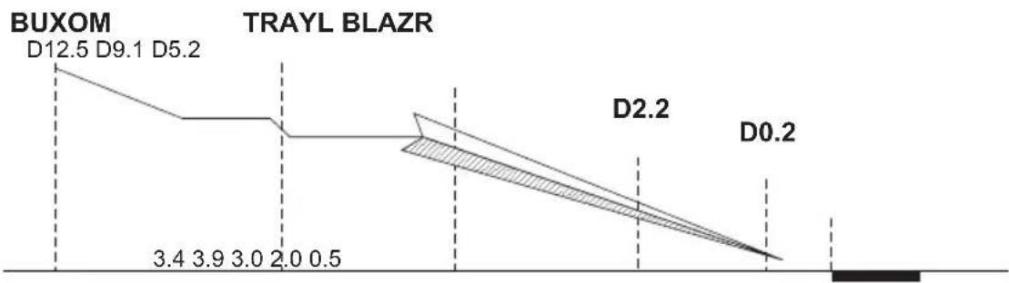
line
| Label | Value | | ----------- | ----- | | BUXOM | D12.5 | | D9.1 | D9.1 | | D5.2 | D5.2 | | TRAYL BLAZR | 3.4 | | D2.2 | 3.9 | | D0.2 | 3.0 | | D0.2 | 2.0 | | D0.2 | 0.5 |-
Prior to intercepting the localizer, or before reaching the BUXOM intersection, set up your Apollo GPS with IVDG LOC-DME as a waypoint.
-
Press DIRECT-TO. Select the IVDG LOC-DME waypoint using the LARGE and SMALL knobs, and then press ENTER.

text_image
LOC-DME IVDG USAThe Apollo GPS CDI may not be aligned with the approach course, only the Nav receiver may be used for course guidance.
- Press NAV on the Apollo GPS to display distance. Note the distance to the IVDG DME to identify the intersections TRAYL (D9.1 IVDG), BLAZR (D5.2 IVDG), D2.2 step down, and, D0.2. Note that if you enter the step-down waypoints into a flight plan, the ILS bearing is 99^ while the bearing shown to the VOR-DME waypoint is 101^ . This difference occurs because the actual physical locations for the DME antenna and the localizer antenna are different.
ETE LIVDG 01:54 0.004 △ BRC 101↑ 5.65NM
DME Data from ILS with Procedure Turn
This example uses the ILS DME approach to Rwy 21L at Prescott, Arizona.
- After reaching the Drake (DRK) VOR, continue to the HUMTY intersection to intercept the outbound localizer course using your Nav receiver for course guidance.
- Before commencing the approach, press DIRECT-TO. Select the IPRC LOC-DME waypoint using the LARGE and SMALL knobs, and then press ENTER.
- Press NAV on the Apollo GPS to display distance. Use your Apollo GPS for DME information to identify the D10.1 point and the HUMTY (D7.2) IAF intersection.
ETE LIPRC 02:08 0.000 △ BRC 209↑ 7.17NM
ILS DME with DME Data from Two VORs on the Field
This example uses the ILS DME approach to Rwy 21 at Flagstaff, Arizona. The DME is co-located with the VOR.
-
Before commencing the approach, press DIRECT-TO. Select the Flagstaff (vFLG) VOR/DME waypoint using the LARGE and SMALL knobs, and then press ENTER.
-
Use your Nav receiver for Localizer and Glideslope guidance.
-
Press NAV on the Apollo GPS to display distance. Use your Apollo GPS for distance information instead of your DME to identify the SHUTR (IAF) intersection at D7.5, the D5.5, and the D1.0 points.
ETE VFLG 02:54 0.001 A BRC 210↑ 8.15NM
VOR DME without GPS Overlay
This example uses the Portland, Oregon VOR DME Rwy 21 approach. You arrive at this approach by going from the Battleground (BTG) VOR to the REENY intersection, making a procedure turn, and then following the 215 radial to the PDX VOR. Use your Nav receiver for course guidance and your Apollo GPS for distance information.
- After reaching the BTG VOR, use your Nav receiver to follow the 061 radial to REENY, and complete the procedure turn.
- After completing the procedure turn, set your Apollo GPS to follow the 215 radial to the PDX VOR. Press DIRECT-TO twice. Select 215 to the (vPDX) VOR/DME waypoint using the LARGE and SMALL knobs, and then press ENTER.
The Apollo GPS CDI may not be aligned with the approach course, if the magnetic variation has changed since the VOR station was commissioned. Only the Nav receiver may be used for course guidance.
- Press NAV on the GPS to display distance. Use your Apollo GPS for distance information to identify the REENY (IAF) intersection at D20.0, the D16.0, D13.0, D9.0 points, and the SOOZN (D5.0) intersection.
CBS DTK: 215° TO
PDX VOR MAN
VOR DME with GPS Overlay
This example uses the Sunriver, Oregon VOR DME Rwy 18 Sunriver GPS overlay approach. This approach has a GPS overlay. So, in this case, you may use your Apollo GPS for distance information instead of the DME, while using the Nav receiver for course guidance.
- Select S21 (Sunriver) as the destination waypoint.
- Press SELECT and then ENTER to load the approach.
- Fly the approach as you would any other GPS approach. The waypoints will sequence appropriately.
Or
- Use the Nav receiver for course guidance.
- Press DIRECT-TO. Select the VOR-DME waypoint using the LARGE and SMALL knobs, and then press ENTER.
- Press NAV on the GPS to display distance. Use the Apollo GPS to monitor DME information to
Approach Examples
identify FORRS (D13.0), CERAB (D18.0), and the missed approach point (D23.0).
DME Arc Example
The following example uses Baltimore's VOR DME 15 to demonstrate the approach to Martin State Airport. The approach uses a 14.7 DME clockwise arc to guide the aircraft to Runway 15.
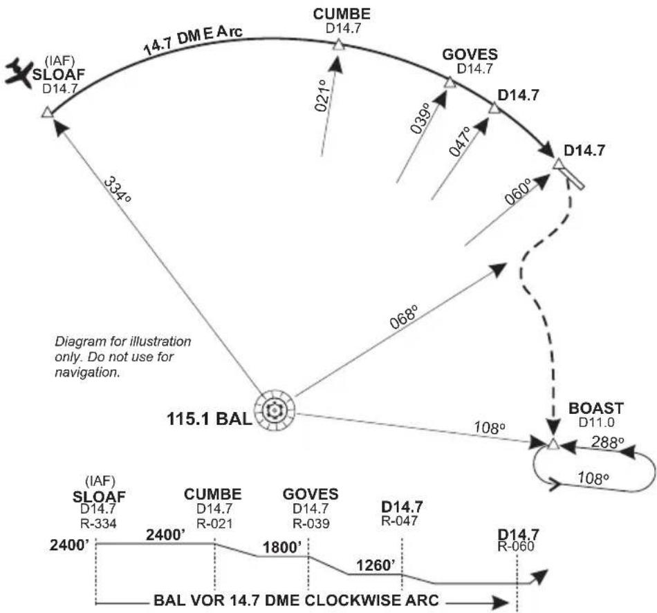
other
| Label | Angle (°) | Direction (°) | |-------------|-----------|---------------| | CUMBE | 021 | D14.7 | | GOVES | 039 | D14.7 | | BOAST | 060 | D11.0 | | BAL VOR | 068 | D14.7 | | (IAF) SLOAF | 334 | D14.7 | | (IAF) SLOAF | 108 | D14.7 | | (IAF) SLOAF | 1260 | D14.7 | | (IAF) SLOAF | 1800 | D14.7 | | (IAF) SLOAF | 2400 | D14.7 | | (IAF) SLOAF | 2880 | D14.7 | | (IAF) SLOAF | 334 | R-334 | | BAL VOR | 1260 | D14.7 | | BAL VOR | 1800 | D14.7 | | BAL VOR | 2400 | D14.7 | | BAL VOR | 2880 | D14.7 | | BAL VOR | 334 | D14.7 | | BOAST | 108 | D11.0 | | BOAST | 1260 | D14.7 | | BOAST | 1800 | D14.7 | | BOAST | 2400 | D14.7 | | BOAST | 2880 | D14.7 | | BOAST | 334 | D14.7 | | CUMBE | 021 | D14.7 | | CUMBE | 039 | D14.7 | | CUMBE | 060 | D14.7 | | CUMBE | 068 | D14.7 | | CUMBE | 060 | D14.7 | | CUMBE | 068 | D14.7 | | CUMBE | 060 | D14.7 | | CUMBE | 068 | D14.7 | | CUMBE | 060 | D15.1 | | CUMBE | 068 | D15.1 | | CUMBE | 060 | D15.1 | | CUMBE | 068 | D15.1 | | CUMBE | 060 | D15.1 | | CUMBE | 068 | D15.1 | | GOVES | 021 | D14.7 | | GOVES | 039 | D14.7 | | GOVES | 060 | D14.7 | | GOVES | 068 | D14.7 | | GOVES | 060 | D14.7 | | GOVES | 068 | D14.7 | | GOVES | 060 | D14.7 | | GOVES | 068 | D14.7 | | GOVES | 060 | D14.7 | | | GOVES | 068 | D14.7 | | GOVES | 060 | D14.7 | | GOVES | 068 | D14.7 | | GOVES | 060 | D14.7 | | GOVES | 068 | D14.7 | | GOVES | 060 | D14.7 | | GOVES | 068 | D14.7 | | GOVES | 060 | D14.7 | | BOAST | 021 | D14.7 | | BOAST | 039 | D14.7 | | BOAST | 060 | D14.7 | | BOAST | 068 | D14.7 | | BOAST | 060 | D14.7 | | BOAST | 068 | D14.7 | | BOAST | 060 | D14.7 | | BOAST | 068 | D14.7 | | BOAST | 060 | D14.7 | | | BOAST | 068 | D14.7 | | BOAST | 060 | D14.7 | | BOAST | 068 | D14.7 | | BOAST | 060 | D14.7 | | BOAST | 068 | D14.7 | | BOAST | 060 | D14.7 | | BOAST | 068 | D14.7 | | BOAST | 060 | D14.7 | | BOAST | 068 | D14.7 | | BOAST | 060 | D14.7 | | BAL VOR | 2400 | BOL | | BAL VOR | 2400 | BOR | | BAL VOR | 2880 | BOR | | BAL VOR | 334 | BOR | | BAL VOR | 334 | BOR | | BAL VOR | 334 | BOR | | BAL VOR | 334 | BOR | | BAL VOR | 334 | BOR | | BAL VOR | 334 | BOR | | BAL VOR | 334 | BOR | | BAL VOR | 334 | BOR | | BAL VOR | 334 | BOR | | BAL VOR | 334 | BOR | | BAL VOR | 334 | BOR | | BAL VOR | 334 | BOR | | BAL VOR | 334 | BOR | | BALVOR | 2400 | BOR | | BALVOR | 2400 | BOR | | BALVOR | 2880 | BOR | | BALVOR | 2880 | BOR | | BALVOR | 2880 | BOR | | BALVOR | 2880 | BOR | | BALVOR | 2880 | BOR | | BALVOR | 2880 | BOR | | BALVOR | 334 | BOR | | BALVOR | 334 | BOR | | BALVOR | 334 | BOR | | BALVOR | 334 | BOR | | BALVOR | 334 | BOR | | BALVOR | 334 | BOR | | BALVOR | 334 | BOR | | BALVOR | 334 | BOR | | BALVOR | 334 | BOR | | BALVOR | 334 | BOR | | BALVOR | 334 | BOR | | BALVOR | 334 | BOR | | BALVOR | 334 | BOR | | BALVOAT | - | - | | BALVOAT | - | - | | BALVOAT | - | - | | BALVOAT | - | - | | BALVOAT | - | - | | BALVOAT | - | - | | BALVOAT | - | - | | BALVOAT | - | - | | BALVOAT | - | - | | BALBOAT A: -B: -B: -B: -B: -B: -B: -B: -B: -B: -B: -B: -B: -B: -B: -B: -B: -B: -B: -B: -B: -B: -B: -B: -B: -B: -B: -B: -B: -B: -B: -B: -B: -B: -B : B: -B: -B: -B: -B: -B: -B: -B: -B: -B: -B: -B: -B: -B: -B: -B: -B: -B: -B: -B: -B: -B: -B: -B: -B: -B: -B: -B: -B: -B: -B: -B: -B: -B:B : B : B : B : B : B : B : B : B : B : B : B : B : B : B : B : B : B : B : B : B : B : B : B : B : B : B : B : B : B : B : B : B : B : B : B : B : B : B : B : B : B : B : B : B : B : B : B : B : B : B : N : N : N : N : N : N : N : N : N : N : N : N : N : N : N : N : N : N : N : N : N : N : N : N : N : N : N : N : N : N : N : N : N : N : N : N : N : N : N : N : N : N : N : N : N : N : N : N : N : N : M : M : M : M : M : M : M : M : M : M : M : M : M : M : M : M : M : M : M : M : M : M : M : M : M : M : M : M : M : M : M : M : M : M : M : M : M : M : M : M : M : M : M / / / / / / / / / / / / / / / / / / / / / / / / / / / / / / / / / / / / / / / / / / / / / / / / / / / / / / / / / / / / / / / / / / / / / / / / / / / / / / / / / / / / / / / / / / / / / / / / / / / /-
Before reaching SLOAF, tune the Nav receiver to the Baltimore VOR. Intercept and follow Baltimore's 334° radial (154° bearing) until you reach SLOAF.
-
In your Apollo GPS, select the BAL VOR as the destination waypoint.
-
Prior to SLOAF, start a turn to approximately 064^ to intercept the published arc.
-
On the Apollo GPS, read the bearing to the BAL VOR. Adjust the aircraft's bearing so the right wing aligns with the bearing to the VOR. In other words,
just plant your right wing on the bearing to BAL as displayed by the GPS and hold the arc.
If the distance drifts lower than 14.7, widen the turn a few degrees by turning left. If the distance drifts higher than 14.7, tighten the turn a few degrees by turning right.
- Dial the 021^ radial on you Nav receiver to identify the CUMBE intersection, when the Nav CDI centers on the 021^ radial.
- Likewise, identify the GOVES intersection on the 039^ radial, the next (D14.7) step down on the 047^ radial, and the missed approach point at the 060^ radial.
- To execute the missed approach, intercept the 068^ radial until reaching 12 nm from BAL as indicated on the Apollo GPS.
- Turn left to intercept the 11 DME arc by planting your right wing on the GPS's bearing and adjusting your turns as necessary to hold the 11 DME arc.
- Dial in the 108^ radial on your Nav CDI. When the CDI centers, you are located at the BOAST intersection. Turn left to 108^ and time your outbound travel for one minute.
- Intercept the 288^ radial to the BAL VOR for your inbound turn. When the GPS indicates 11 DME to BAL, you are at the BOAST intersection. Continue to hold as necessary.
Approach Examples
Notes
Approach Notes
Waypoints The database waypoints which describe the TSO
C129a GPS approaches correspond with the waypoints which appear on the approach procedure charts whenever possible. VORs, NDBs, and named Intersections will appear in the approach sequence as they are on the charts. The Rifle, Colorado VOR will be identified RIL, the Turno Locator/Outer-Marker (LOM) at Salem, Oregon will be identified SL, the Forsyth NDB, at Forsyth Montana will be identified FOR, and the HIKOX intersection, used as an Initial Approach Fix (IAF) for VOR/DME or GPS RWY 3 approach at Casper Wyoming, will be identified as HIKOX.
Many waypoints that are specific to TSO-C129a/JTSO-C129a GPS approaches require that a name be assigned to them, such as an Initial Approach Fix (IAF) which is shown on the approach procedure chart as a radial and distance from a VOR. These waypoints may or may not appear on the approach procedure charts. Jeppesen includes the names of many of these waypoints on their approach procedure charts; however, these names are usually not included on National Ocean Service (NOS) charts.
TSO/JTSO C129 Overlay
TSO-C129a/JTSO C129a requires the equipment to prompt the pilot to enter the local altimeter setting, if not already entered, at 3 nm inbound to Final Approach Fix, FAF. It also requires that the equipment change RAIM alarm limits from 1 nm to 0.3 nm and to begin changing CDI sensitivity from 1 nm full-scale deflection to 0.3 nm full-scale deflection when 2 nm inbound to the FAF. The TSO also requires that the final leg of the approach be defined as a path between the FAF and the MAP waypoints (bearings to or from waypoints are not allowed for the final segment). For these reasons, a GPS TSO C129a approach must always have an FAF lying on the inbound course to the MAP, even when there is no
such waypoint in the underlying approach. There are many GPS overlay approaches, such as the VOR or GPS-B approach to Wenatchee Washington, where there is no FAF inbound. The EAT VOR is the Initial Approach Fix (IAF), Final Approach Fix (FAF), Missed Approach Point (MAP), and Missed Approach Holding Point (MAHP). When there is no FAF inbound waypoint for a GPS approach, it is necessary to add one so that the equipment can do these TSO required tasks. This equipment-required FAF is called a sensor FAF and it is always located on the final approach course prior to the MAP. If there is already a named waypoint which can be used, it becomes the sensor FAF. If not, a sensor FAF waypoint is created. In the Wenatchee approach example, this waypoint is named FF285. FF285 is the sensor FAF and the inbound course for the approach is 285°. FF285 appears on the Jeppesen approach procedure chart, but not on the National Ocean Service (NOS) approach procedure chart for this approach.
This is especially important to understand when a procedure turn or course reversal is required. If you are inbound from the CASHS intersection, a procedure turn is required. You must execute this procedure turn on your Apollo GX relative to FF285, the TSO-C129a/JTSO-C129a FAF, not relative to the EAT VOR as depicted on the NOS chart as it is necessary to cross this sensor FAF waypoint inbound in order for the Apollo GX to go approach active (approach active annunciator lit) and allow you to complete the approach. This is clearly depicted on the Jeppesen approach procedure chart.
Reproduced with permission of JeppesenSanderson Inc.
Reduced for illustrative purposes.
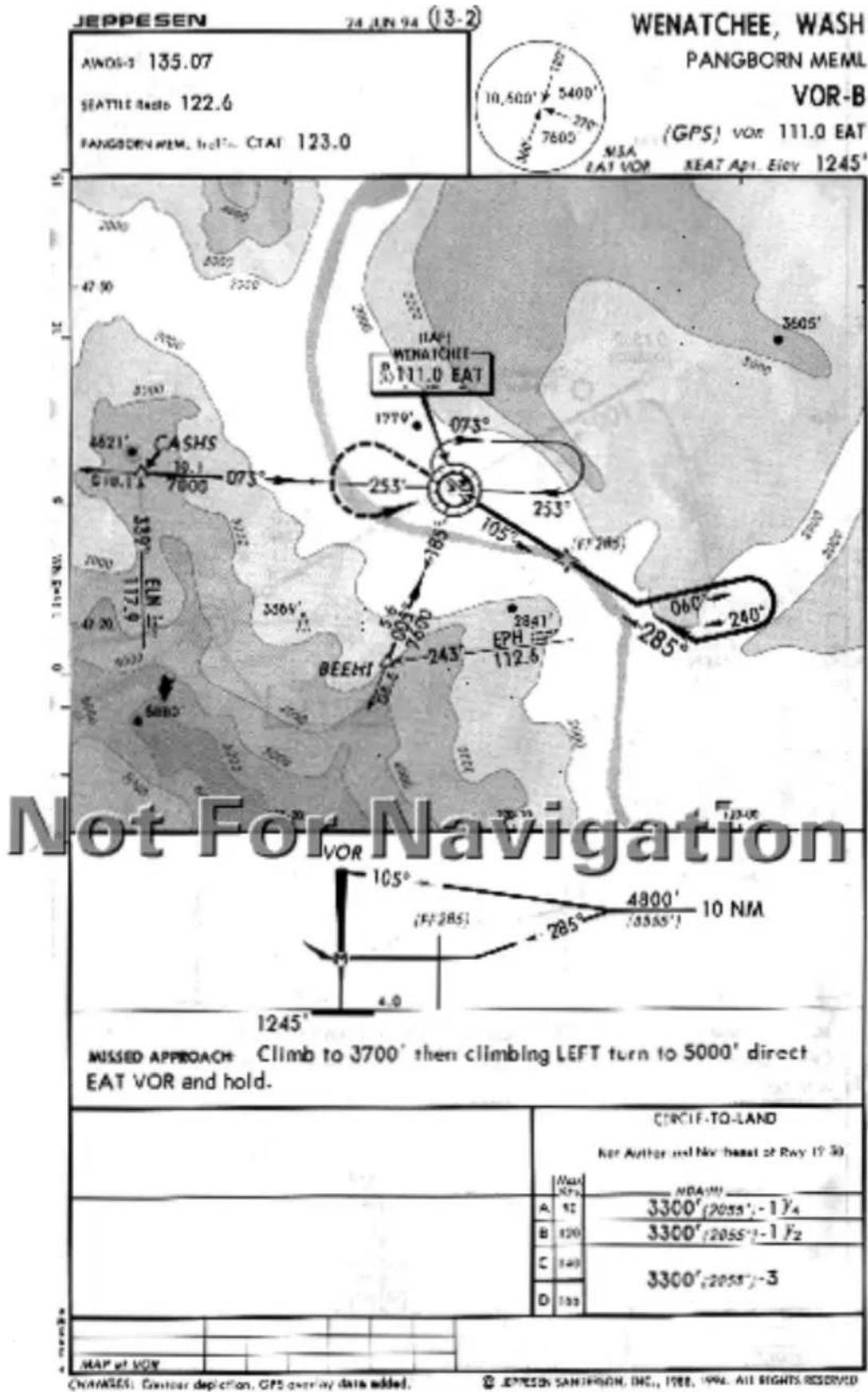
geo
| Direction | Value | | --------- | ----- | | Left | 1779° | | Right | 253° | | Bottom | 285° | | Center | 4800' | | Right | 1245° | | Bottom | 1245° | | Right | 1245° | | Center | 1245° | | Right | 1245° | | Bottom | 1245° | | Right | 1245° | | Center | 1245° | | Right | 1245° | | Bottom | 1245° | | Right | 1245° | | Center | 1245° | | Right | 1245° |Approach Notes
Another type of waypoint which will have a name in your Apollo GX database, but may or may not appear on your approach procedure chart is an IAF waypoint defined as a radial and distance from a VOR. An example would be the VOR DME RWY 4 approach to North Bend, Oregon. The IAF at the OTH 164 radial at 14 nm is contained in the Apollo GX database as D164N (“D” for DME, 164 for 164 radial, and “N,” the 14th letter of the alphabet, for 14 nm.). It is also depicted on Jeppesen approach procedure charts with this name; however, this name is not found on NOS charts.
Charts have been reduced for illustrative purposes.
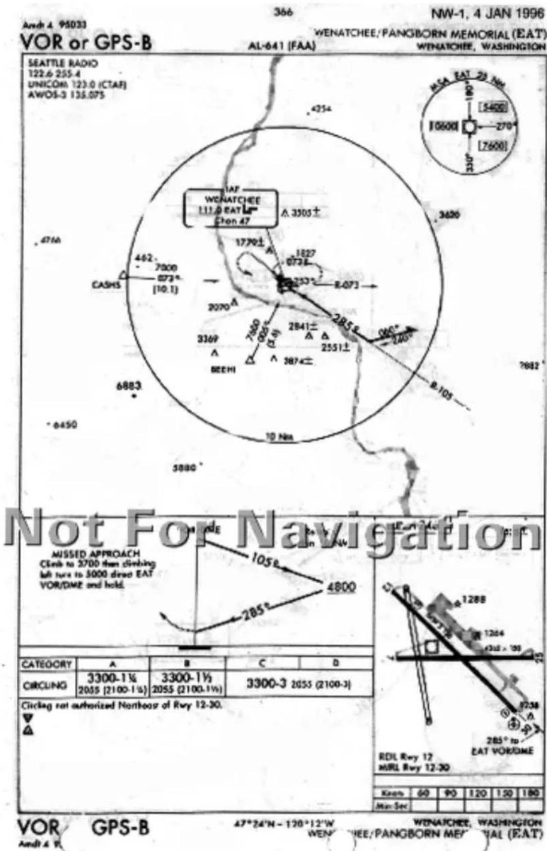
Approach Notes
There are several other types of waypoints which may appear in your Apollo GX loaded approach and which may or may not appear on your approach procedure charts.
Following is a brief description of these types of waypoints and the naming convention followed.
Identificatio n
Each waypoint in an Apollo GX flight plan has an identifying type and a name. There are a few exceptions, where some approach waypoints may be “undefined.” When you view the flight plan legs, by turning the SMALL knob while viewing a flight plan in FLIGHT PLAN mode, the display will show a “FROM” waypoint and a “TO” waypoint for each leg. Under the names for the waypoint, the waypoint type is usually displayed although this field may be changed by pressing SEL and turning the SMALL knob to show other information such as leg ETE. The FROM-TO-NEXT page, located one click to the left of the ‘home’ navigation page, always shows the waypoint names and types for this two-leg “window” view of your active flight plan.
Most of the waypoint types for en route waypoints are quite familiar. They include ARPT for Airport, VOR, NDB, INT for intersection and USER for a user-defined waypoint.
The approach waypoint types will usually also have familiar types, but there may be a few types which are new. The approach waypoint types include:
IAF Initial Approach Fix
FAF Final Approach Fix. Note that there must always be a Final Approach Fix inbound for TSO C129a approaches. When an underlying approach, such as a VOR or NDB approach does not have an inbound FAF, one is created or added.
IFAF Combined Initial and Final Approach Fix with no intermediate waypoints. (Sometimes a procedure turn
or course reversal is required - this usually depends on the direction of flight).
MAP Missed Approach Point
MAHP Missed Approach Holding Point
ARC A DME arc terminator. The preceding flight plan leg is described as an arc to this waypoint. An ARC waypoint may follow another ARC waypoint.
APPR An intermediate approach waypoint. These are sometimes used as step-down fixes or to define a course to the next approach waypoint.
An Apollo GX TSO C129a approach will always begin at an IAF. It will always contain at a minimum an IAF, FAF, MAP, and MAHP sequence. The IAF and FAF may be combined. Waypoints may be used more than once; the same waypoint could be the IAF, the MAP, and the MAHP; however, TSO C129a non-precision approaches require that there always be a distinct FAF to MAP leg. Intermediate waypoints, of type APPR or ARC, may be anywhere in the sequence except between the FAF and the MAP.
The following example uses the VOR DME RWY 12 GPS-overlay approach to Baker City Oregon.
The Apollo GX has a flight plan loaded from the Salem, Oregon airport to the Deschutes VOR, DSD, to the Baker City airport, BKE. An approach, the VOR DME RWY 12 approach with the D272Y (waypoint on the BKE VOR 272 radial at 25 nm.) IAF is selected and loaded. When viewing the flight plan legs, the following legs may be viewed.

text_image
SLE TO DSD 1.100° 82.6NM ARPT VOR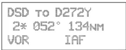
text_image
DSD TO D272Y 2* 052° 134NM VOR IAFApproach Notes
The following legs replace the BKE airport in the flight plan and describe the approach sequence.
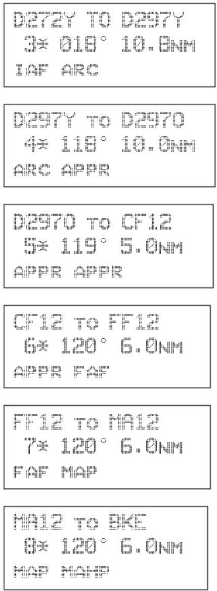
text_image
D272Y TO D297Y 3* 018° 10.8NM IAF ARC D297Y TO D2970 4* 118° 10.0NM ARC APPR D2970 TO CF12 5* 119° 5.0NM APPR APPR CF12 TO FF12 6* 120° 6.0NM APPR FAF FF12 TO MA12 7* 120° 6.0NM FAF MAP MA12 TO BKE 8* 120° 6.0NM MAP MAHPNotice that these waypoints are all depicted on the example Jeppesen Approach plate; however, only BKE is depicted as such on the NOS plate (shown on the following page).
Reduced for illustrative purposes.

SALT LAKE CITY Center (R) 128.05
McMINNVILLE Radio 122.4
BAKER CITY MUN UNICOM CTAF 123.0
When Class E airspace not effective, procedure not authorized.
BAKER CITY MUN
VOR DME Rwy 12
(GPS) vor 115.3 BKE
/ MSA
BKE VOR
KBKE Apt. Elev 3369
MISSED APPROACH: Climbing RIGHT turn to 7000' outbound via BKE VOR R-300 within 15 NM, then direct BKE VOR and hold. All maneuvering NORTH side of BKE VOR R-300.
| STRAIGHT-IN LANDING RWY 12A,B,C:MDA(H)3760'(398')D:MDA(H)4360'(998') | CIRCLE-TO-LANDMaxKtsMDA(H) | |||||||
| A | 1 | 903780'(411')-1 | ||||||
| B | 1203820'(451')-1 | |||||||
| C | 1403820'(451')-1 12 | |||||||
| D | 3 | 1654360'(991')-3 | ||||||
| MAP at D0.8 | ||||||||
CHANGES: Contour depiction, GPS overlay data added.
© JEPPESEN SANDERSON, INC., 1987, 1994. ALL RIGHTS RESERVED.
Charts have been reduced for illustrative purposes.
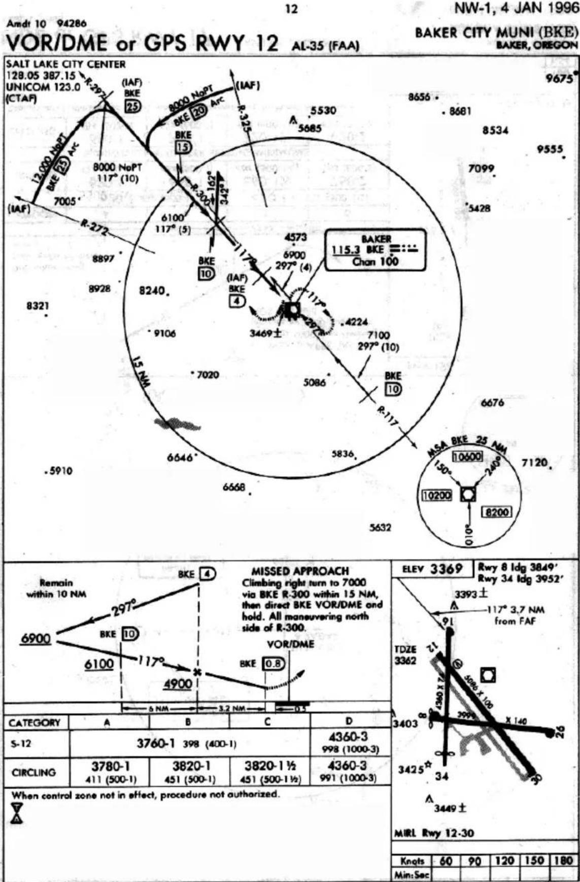
radar
SALT LAKE CITY CENTER | Direction | Distance (Nm) | Latitude (°) | Longitude (°) | | :--- | :--- | :--- | :--- | | R-272 | 12000 | 8000 | 117 | | R-272 | 12000 | 8000 | 117 | | R-272 | 12000 | 8000 | 117 | | R-272 | 12000 | 8000 | 117 | | R-272 | 12000 | 8000 | 116 | | R-272 | 12000 | 8000 | 116 | | R-272 | 12000 | 8000 | 116 | | R-272 | 12000 | 8000 | 116 | | R-272 | 12000 | 8000 | 115 | | R-272 | 12000 | 8000 | 115 | | R-272 | 12000 | 8000 | 115 | | R-272 | 12000 | 8000 | 115 | | R-272 | 12000 | 8000 | 114 | | R-272 | 12000 | 8000 | 114 | | R-272 | 12000 | 8000 | 114 | | R-272 | 12000 | 8000 | 113 | | R-272 | 12000 | 8000 | 113 | | R-272 | 12000 | 8000 | 113 | | R-272 | 12000 | 8000 | 112 | | R-272 | 12000 | 8000 | 112 | | R-272 | 12000 | 8000 | 112 | | R-272 | 12000 | 8000 | 111 | | R-272 | 12000 | 8000 | 111 | | R-272 | 12000 | 8000 | 111 | | R-272 | 12000 | 8000 | 111 | | R-272 | 12000 | 8000 | 110 | | R-272 | 12000 | 8000 | 110 | | R-272 | 12000 | 8000 | 110 | | R-272 | 12000 | 8534 | 9555 | | R-272 | 12555 | 9675 | | | R-335555555555555555555555555555555555555555555555555555555555555555555555555555555555555555555555555555 | | R-33555555555555555 | | | | | | | | | | | | | | | | | | | | | | | | | | | | | | | | | | | | | | | | | | | | | | | | | | | | | | | | | | | | | | | | | | | | | | | | | | | | | | | | | | | | | | | | | | | | | | | | | | | | | | RESISTED APPROACH Climbing right turn to 7000 via BKE R-300 within 1.5 NM, then direct BKE VOR/DME and hold. All maneuvering north side of R-3/3. VOR/DME ELEV:3369 Rwy:8 ldg:3849' Rwy:34 ldg:3952' 3393± A 117°3.7 NM from FAF TDZE 3362 3463 3463 3463 3463 3463 3463 3463 3463 3463 3463 3463 3463 3463 3463 3463 3463 3463 3463 3463 3463 3464 3464 3464 3464 3464 3464 3464 3464 3464 3464 3464 3464 3464 3464 3464 3464 3464 3464 3464 3464 3466 3466 3466 3466 3466 3466 3466 3466 3466 3466 3466 3466 3466 3466 3466 3466 3466 3466 3466 3466 3467 3467 3467 3467 3467 3467 3467 3467 3467 3467 3467 3467 3467 3467 3467 3467 3467 3467 3467 3467 MIRL Rwy:12-3D CATEGORY:A B C D S-12 376O-1 398(4O-O-1) 436O-3 998(1OOO-3) CIRCLING 378O-1 382O-1 382O-1½ 436O-3 41I(5O-O-1) 45I(5O-O-Ⅰ½) 99I(1OOO-Ⅱ) When control zone not in effect, procedure not authorized. Knots 6O 9O 12O 15O 18O Min:Sec.VOR/PE or GPS R'Y 12 ^44^50'N-117^49'W
Amdt 10 94
BAKER, OREGON BAKER CITY 11 (BKE)
Naming Conventions
When a name must be provided for an otherwise unnamed waypoint, the naming will use the ARINC-424, chapter 7 specified convention whenever possible. There are a few types of waypoints, DME arc waypoints greater than 26 nm from the reference and single character NDB idents, which are not adequately addressed by the ARINC-424 specification. Most of these names are intuitive after you understand a few of the rules. The entire ARINC naming conventions are not included here, but the following guidelines will probably explain the names you see assigned to these waypoints.
Exceptions
DME arc or DME-distance/bearing waypoints that are greater than 26 miles from their reference point. The standard ARINC convention for DME arc or DME-distance/bearing (sometimes called Rho-Theta) waypoints is to use 'D' followed by the bearing from the waypoint, followed by an Alpha character from A to Z corresponding to the number of miles, from 1 to 26, rounded to the nearest whole mile. A waypoint on the BKE VOR 272 radial at 25 nm would then be named D272Y as is the IAF in the Baker, Oregon approach example above. When the distance is greater than 26 miles, such as for the Topeka, KS VOR DME RWY 3 approach, the waypoint is named by using the first two characters of the reference navaid ID, followed by the bearing from the navaid. The IAF at the Topeka VOR, TOP, located on the 231 radial at 31 nm is then named TO231. The IAF on the TOP 176 radial at 31 nm is named TO176.
Canada and some South American countries have multiple NDBs with the same ident. When these are in the same ICAO region, they can't both be in the data. When this happens, one airport which uses a Golf NDB, “G,” would have the waypoint named “G.” The next airport that uses a “G” NDB in the approach waypoints would have a waypoint named with the 1 letter ident and ‘NB’ for NDB appended to
Approach Notes
it; therefore, it would appear in the database as “GNB” at the second airport.
Standard Naming Convention s
In general, the following codes are used to correspond to a waypoint type. When they are associated with an approach to a specific runway, the runway is appended. When the approach is not to a specific runway, the approach bearing is appended. These codes are:
FF Final Approach Fix
CF Final Approach Course Fix (used when necessary to define a course to the FAF—all VOR DME approaches require a course fix waypoint).
MA Missed Approach Point
RW Runway Fix
Following the characters will either be a runway number, when associated with a particular runway, or a bearing corresponding to the course at that waypoint. A missed approach point that corresponds to a RWY 12 approach, would then be called MA12 if it is not the runway threshold. If the MAP were the runway threshold, it would be named RW12. A missed approach point associated with a VOR-A approach, where there are no published straight-in minimums to any runway, and where the final approach course is 120 would be named MA120.
Bearing and Distance Waypoints: Distance/bearing waypoints (sometimes called Rho - Theta waypoints), that are defined as a bearing and distance from a VHF navaid, are named with the character “D,” followed by the radial on which they are positioned, followed by a single alpha character from “A” to “Z” that corresponds to a distance from 1 to 26 nm. Thus a waypoint that is on a 350^ radial at 10 nm will be named D350J and a waypoint that is on the 250 radial at 15 nm would be named D250O.
Unnamed turn points, intersections, and bearing/distance waypoints: Idents for unnamed turn points, intersections, or bearing/distance waypoints (other than VHF navaid distance/bearing), that are not coincidental with named waypoints, are constructed by using the ident of the nearest navaid together with the distance (rounded to whole miles). If the distance is less than 100 nm, the distance follows the navaid ident. If the distance is 100 nm or more, the last two digits of the miles are placed in front of the navaid ident. For example:
| NAVAID DISTANCE IDENT | ||
| INW 18 INW18 | ||
| CSN 106 | 06CSN | |
| TCS | 89 | TCS89 |
These are most often used for identifying bends in airways that occur at unnamed positions and other en route uses. It is unlikely that you will often see this convention used to name any approach waypoints, but you will occasionally.
Phase II GPS Approaches
GPS equipment may be used as the primary IFR flight guidance during a non-precision approach without actively monitoring the applicable navaid(s) which define the approach being used. However, the traditional ground-based navaid(s) required for the published approach and alternate should be operational and the associated avionics installed and operational. The approach should be requested and approved by its published name, such as “NDB Runway 24.” Modification of the published instrument approach name is not required.

Phase III GPS Approaches
Note
Jeppesen Approach Procedure Charts identify Phase-2 overlay approaches by printing GPS contained in parenthesis, (GPS) along with the procedure name.
Phase III GPS approaches must contain GPS in the title of the GPS procedure such as VOR or GPS RWY 24. Neither the ground station navaid(s) nor the traditional aircraft avionics is required. If the approach is to be flown using the Apollo GX, it should be requested and approved by the GPS name, such as GPS RWY 24. If it is to be flown with the traditional avionics, it should be requested and approved by that name, such as VOR RWY 24.
You should always plan the route and approach to any required alternate airport as if a supplementary navigation system, such as GPS or Loran-C, may not be available. The traditional en route and approach Navaids must be operating and the aircraft must have the required avionics to use for required alternates. You may use a supplementary system, such as GPS, to navigate to an alternate airport. You may execute a GPS approach to a required alternate, but you must plan for the possibility that GPS navigation will not be available.
FAA guidelines on IFR use of GPS and GPS approaches are contained in an FAA Advisory Circular (AC), AC 90-94. You should be familiar with the information in this AC before attempting GPS approaches.
In order to use the Apollo GX for an approach, the approach must be selected from the Apollo GX database and loaded into the active flight plan. Only approaches found in the Apollo GX database may be flown with the Apollo GX.
Comm Radio Operation
This section introduces the basic operating details of the VHF Communications Transceiver portion of the Apollo GX60/65. The Comm information is displayed in the bottom row of the display: Active (A) and Standby (S) frequencies. The Active (A) indicator changes to “Tx” when you are transmitting. The Standby (S) indicator changes to an “m” when the monitor function is used. The Smart keys will change when you press the COM key to add the Monitor (MON), Recall (RCL), Memory (MEM), and Flip/Flop (<->) functions. The Standby (S) frequency is reversed when Comm Radio operation is selected.

text_image
ETE SLE 01:23 1.006 △ Brc 126 1234M A119.10 s118.75 MSG MON RCL MEM ↔ Standby Frequency Monitor Recall Memory Flip/FlopPower On/Off
Turn the Power/Volume control clockwise past the OFF detent.
Volume Turn the Power/Volume control clockwise to increase the volume level and counterclockwise to decrease volume.
SMALL and LARGE Knobs
The dual concentric knobs on the right side of the GX60/65 are used to select frequencies or other options. The LARGE outer knob is used to change the MHz value in 1 MHz steps.
The SMALL inner knob changes the kHz values in 25 kHz steps.
The LARGE and SMALL knobs are used to view different functions and for editing. Other functions will be described in the affected section.
Selecting Frequencies
New frequencies are first selected as a Standby frequency and then toggled to the Active side when desired. While viewing the frequency display, use the LARGE and SMALL knobs on the right side of the GX60/65 to select the desired frequency. The Standby frequency is highlighted (reversed).
- Press COM to reach the Comm radio function. The Smart keys will change to show the Comm functions.
- Turn the LARGE knob to change the Standby frequency values in one MHz increments. The MHz selection range is between 118 and 136 in one MHz steps.
- Turn the SMALL knob to change the Standby frequency values in 25 kHz increments. The kHz selection range is between 000 and 975 kHz in 25 kHz steps. Note that only two digits are displayed to the right of the decimal point.
Turn the LARGE and SMALL knobs clockwise to increase and counterclockwise to decrease the frequency values. Standby frequency selection is not inhibited during transmit.
Press the FLIP/FLOP key (internal or external) to toggle the Standby or recalled frequency to the Active frequency.
Comm Mode Map Display
The first page of the Map mode includes the moving map, TO waypoint, range to the TO waypoint, ground speed, bearing to the TO waypoint, track, Active and Standby frequencies, distance off-track, and the map scale.
While viewing the map display, press the COM smart key to allow access to the Comm radio functions. When the Standby frequency is highlighted, use the LARGE and SMALL keys to change the Standby frequency. Press the MAP key to return to the Map functions.

text_image
Distance to the TO Waypoint TO Waypoint Identifier Bearing to the TO Waypoint Ground Speed Current Track Route Line 7S9 2S6 3S2 4: 7S9 MMV SLE Your Present Position Message Key MSG MON RCL MEM ↔ Monitor Key Recall Key Cross Track Error Distance & Direction Memorize Key Flip/Flop KeyFrequency Monitoring
The Frequency Monitoring function allows you to listen to the Standby frequency, while monitoring the Active frequency for activity.
Press the MON key in the Comm function to listen to the standby frequency. A small “m” is displayed in front of the Standby frequency.
When the Active frequency receives a signal, the unit will switch automatically to the Active frequency. The volume and sound quality will be slightly less for the Standby frequency. The Active frequency quality is not affected. The Frequency Monitor function is inhibited while you are transmitting.
Recalling a Frequency
The GX60/65 can access several areas of stored frequencies. The GX60/65 can access airport frequencies from its database of: Nearest, TO, FROM, INFO, automatically stored active, User stored, weather, and emergency frequencies.
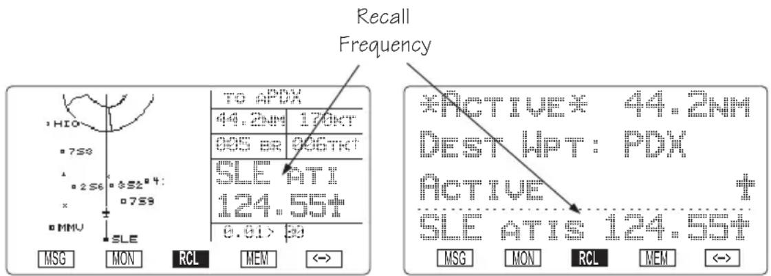
text_image
Recall Frequency HIO 7S3 2S6 *S2*4: 7S9 MMV SLE TO APDX 44.2NM 170KT 005 BR 005TKT SLE HTI 124.559# 0.91 > 30 *ACTIVE: 44.2NM DEST WPT: PDX ACTIVE SLE ATTIS 124.559# MSG MON RCL MEM <>Frequency Abbreviations
TWR - Tower frequency GRND - Ground frequency ATIS - ATIS frequency ATF - Air Traffic Frequency APPR - Approach CLR - Clearance/Delivery CTAF - Common Traffic Advisory Frequency DEP - Departure frequency UNIC - Unicom frequency MF - Mandatory Frequency AWOS - Automated Weather Observation System CNTR - Area Control Center FSS - Flight Service Station UNKN - Unknown
-
In the Comm function, press RCL to view the Frequency Database. The diamond on the right side of the Comm display indicates that more frequencies are available. If there are no other frequencies, the diamond will not appear.
-
Turn the LARGE knob to select the recalled frequency type (Nearest, Info, Destination, etc.). Turn the SMALL knob to display the available frequencies. The waypoint identifier, type, and frequency are displayed.
3a. Press ENTER to move the displayed frequency into the Standby frequency position.
or
3b. Press the FLIP/FLOP key to move it into the Active position.

flowchart
graph TD
    A["Nearest Frequencies"] --> B["Freq 1 ... Freq 15"]
    C["INFO Frequencies"] --> D["Freq 1 ... Freq 15"]
    E["Destination Frequencies"] --> F["Freq 1 ... Freq 15"]
    G["TO or Next Frequencies"] --> H["Freq 1 ... Freq 15"]
    I["FROM Frequencies"] --> J["Freq 1 ... Freq 15"]
    K["Auto Stored List (AUTO)"] --> L["Freq 1 ... Freq 10"]
    M["User Memory (USER)"] --> N["Freq 1 ... Freq 10"]
    O["Weather"] --> P["Freq 1 ... Freq 7"]
    Q["Emerg. Channel"] --> R["Freq 1 ... Freq 7"]
Nearest Frequency
The frequency list for the last Nearest Airport viewed will be available in the Comm function when you press RCL. If a diamond appears on the right, turn the SMALL knob to view more frequencies.
INFO Frequency
You may view up to 15 frequencies for the last airport viewed using the Info function. If a diamond appears on the right, turn the SMALL knob to view more frequencies.
While viewing the frequencies for an airport after pressing INFO, note that the three center smart keys change to show the displayed frequency types. Press the smart key for the frequency type to load it into the Standby frequency.
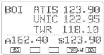
text_image
B0I ATIS 123.90 UNIC 122.95 TWR 118.10 A162.40 s123.90 MSG □ □ TWRLNATI COMDestination, TO, and FROM Frequencies
You can access up to 15 airport frequencies referenced to your TO and FROM waypoints. Turn the SMALL knob to view the frequencies. Press the internal or external FLIP/FLOP key to load the displayed frequency into the Active frequency. Press the ENTER key to load it into the Standby frequency.
Auto Stored Frequencies (Auto)
The GX60/65 keeps track of the last ten Active frequencies and stores them in a stack. When a new frequency is used, it becomes number one on the stack and the old number ten frequency is removed. Each time a new Active frequency is used, the last (tenth) frequency is automatically dropped off the list. Duplicate frequencies are not stored; one instance of the selected frequency becomes Freq 1 on the list.

flowchart
graph TD
    A["NEW"] --> B["Freq 1"]
    B --> C["Freq 2"]
    C --> D["..."]
    D --> E["Freq 9"]
    E --> F["Freq 10"]
    F --> G["OLD"]
- In the Comm function, press RCL and then turn the LARGE knob to display the Auto Stack List (Auto).
- Turn the SMALL knob to view the stored frequencies. The last used frequency is shown at the top of the list.
User Stored Frequencies
When you press the MEM key the Standby frequency is stored in User memory. The GX60/65 stores the last ten frequencies selected by the user. The next time a new User frequency is stored, the last (tenth) frequency is automatically dropped off the list. Duplicate frequencies are not stored.
- Press MEM to store the Standby frequency.
2 Press RCL and then turn the LARGE knob to view the last stored User frequency. - Turn the SMALL knob to view the other User stored frequencies.
Weather Channels
The standard weather channels are stored in the memory of the GX60/65. Weather channels are not available in all databases. You cannot transmit on a weather channel frequency.
- Press RCL and then turn the LARGE knob to display the Weather channel memory.
- Then, turn the SMALL knob to view the available weather channels.
Weather Frequencies
| (When available) |
| 162.400 MHz |
| 162.425 MHz |
| 162.450 MHz |
| 162.475 MHz |
| 162.500 MHz |
| 162.525 MHz |
| 162.550 MHz |

Note
You can search for the best local weather by inserting a Weather frequency into the Standby position, pressing MON, and then turning the SMALLknob to scroll through the Weather channel choices.
Emergency Channel
The standard emergency channel (121.50 MHz) is stored in the memory of the GX60/65.
- In the Comm function, press RCL and then turn the LARGE knob to display the Emergency channel memory.
- Press the FLIP/FLOP key to load the Emergency Channel into the Active frequency or press ENTER to load it into the Standby frequency.
Intercom Function
When two headphone and microphone jacks are connected to the GX60/65, these headsets can be used as a voice-activated intercom.
When you select the Intercom function with the installed selector switch, the intercom function is enabled. The Volume control will control the headphone listening level. The receive function will automatically become active when a signal is detected. Receiver audio volume will be reduced when the intercom is selected.
The Intercom Squelch Sensitivity can be set in the System Functions on page 10-10.
Stuck Mic The GX60/65 helps protect you from a situation where the microphone may get stuck in the ON or Transmit position. If the microphone is keyed for longer than 35 seconds, the GX60/65 will return to the receive mode on the selected frequency.
The statement “Stuc Mic” will appear on the display in Standby frequency position until the transmit key is released. In the Moving Map function, the statement will be “Stuck.”
Com Radio System Information (GX60/65 Only)
The Com Radio information page in the System Function provides system level details about the operation of the Comm radio function. Information includes: software version, rf signal strength, audio noise level, side tone adjustment, intercom squelch, and headphone level.
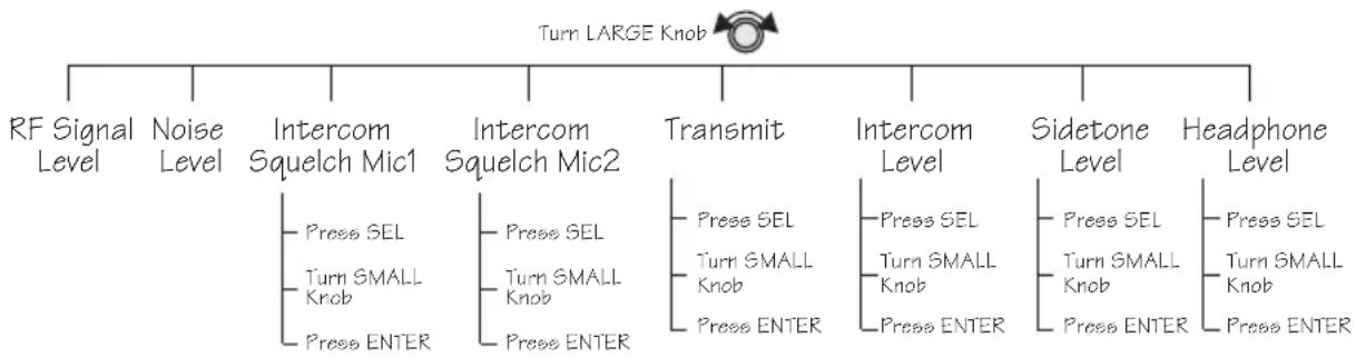
flowchart
graph TD
    A["Turn LARGE Knob"] --> B["RF Signal Level"]
    A --> C["Noise Level"]
    A --> D["Intercom Squelch Mic1"]
    A --> E["Intercom Squelch Mic2"]
    A --> F["Transmit"]
    A --> G["Intercom Level"]
    A --> H["Sidetone Level"]
    A --> I["Headphone Level"]
    D --> J["Press SEL"]
    D --> K["Turn SMALL Knob"]
    D --> L["Press ENTER"]
    E --> M["Press SEL"]
    E --> N["Turn SMALL Knob"]
    E --> O["Press ENTER"]
    F --> P["Press SEL"]
    F --> Q["Turn SMALL Knob"]
    F --> R["Press ENTER"]
    G --> S["Press SEL"]
    G --> T["Turn SMALL Knob"]
    G --> U["Press ENTER"]
    H --> V["Press SEL"]
    H --> W["Turn SMALL Knob"]
    H --> X["Press ENTER"]
Press SYS and then turn the LARGE knob to reach the Comm Radio Information page. Press ENTER.

text_image
COMM INFO PRESS ENTERRF Signal Strength
The RF Signal Level function shows the relative signal strength of the frequency you are listening to. The range displayed is between 0 and 255. The value will constantly change while you are viewing it as signal conditions change.
RF SIGNAL LEVEL 119:10 087
Noise Level
The Noise Level function shows the relative received noise level of the frequency you are listening to. The range displayed is between 0 and 255. The value will constantly change as you are viewing it as signal conditions change. A higher number indicates more noise.
NOISE LEVEL 119.10 087
Intercom Squelch Level Adjustment
The Intercom Squelch Level Adjustment pages are used to display and adjust the Intercom Squelch level to match the sensitivity for your system and personal needs. You may set the levels individually for Mic 1 and Mic 2. The range is from 0 to 127, with the higher number being more sensitive. A low value allows more noise/sound through the intercom to allow for speaking when there is more noise in the background. A higher value reduces noise/sound allowed through the intercom.
- In the Comm Radio Information function, turn the LARGE knob to each Intercom Squelch Level page.
INTERCOM SQUELCH Mic 1 107
- Press SEL and then turn the SMALL knob to adjust the level. Press ENTER to activate the desired level.
INTERCOM SQUELIGH HTC 1 095
Transmit Mic Selection
The Transmit Mic selection page allows to select which microphones are available for transmitting. The choices are Mic 1 and Mic 2, Mic 1, or Mic 2.
- In the Comm Radio Information function, turn the LARGE knob to the Transmit Mic selection page.
TRANSMIT USING MIC 1 AND MIC 2
- Press SEL and then turn the SMALL knob to select your choice. Press ENTER to activate the selection.
Intercom Level
The Intercom Level page allows you to control the noise/sound listening level. A low value allows less noise/sound through the intercom for listening. A higher value increases noise/sound allowed through the intercom.
- In the Comm Radio Information function, turn the LARGE knob to the Intercom Squelch Level page.
INTERROOM LEVEL 000
- Press SEL and then turn the SMALL knob to adjust the level. Press ENTER to activate the desired level.
INTERCOM LEVEL 105
Sidetone Level Adjustment
The Sidetone Level Adjustment page is used to display and adjust the headphone sidetone level. This value controls the volume while you are transmitting.
- In the Comm Radio Information function, turn the LARGE knob to view the Sidetone Level Adjustment page.
SIDE TONE LEVEL 000
- Press SEL and then turn the SMALL knob to adjust the level. Press ENTER to activate the desired level.
SIDEETONE LEVEL 128
Headphone Level Adjustment
The Headphone Output Level (volume) can be set on this page to override the use of the volume knob. This value affects the volume for listening. If the value is set to 000, volume is then controlled by the volume knob.
- In the Comm Radio Information function, turn the LARGE knob to view the Headphone Level Adjustment page.
HEADPHONE LEVEL QQQ
- Press SEL and then turn the SMALL knob to adjust the level. Press ENTER to activate the desired level.
HEADPHONE LEVEL 128
Start Up Displays
The Start Up Sequence runs each time the unit is powered on. The Start Up Sequence varies between units due to installation differences. The initial start up message is displayed for about three seconds.
Apollo GX
- 000000
- 000000
- 000000
- 000000
- 000000
- 000000
- 000000
- 000000
- 000000
- 000000
- 000000
- 000000
- 000000
- 000000
- 000000
- 000000
- 000000
- 000000
- 000000
- 000000
- 000000
- 000000
- 000000
- 000000
- 000000
- 000000
- 000000
- 000000
- 000000
- 000000
- 000000
- 000000
- 01111111111111111
Startup Bypass
SKIP
During the startup sequence, press the SKIP “smart” key to stop the initial testing. You will be able to use all functions.
Quick Comm (GX60/65 Only)
COM
Press the COM key during the startup sequence to enable immediate use of the Comm function in the GX60/65.
Comm Radio Test (GX60/65)
In the GX60/65, if the Comm software fails, the following message will be displayed. You must then have the unit serviced before you can use it.
COM RADIO
If your Apollo GX suffers both EEPROM and RAM failure, you must reset the unit type. Select the unit type with the SMALL knob and then press ENTER. This will allow you the ability to still use the Comm and Approach functions.
MEMORY FAILURE SELECT UNIT TYPE GX60
Owner Message
If the owner name has been previously entered (in System Mode), this page with your name is displayed for three seconds. No owner info screen is displayed if the user has not entered the owner data.
PROPERTY OF: II Horizon INC
Memory Tests
Your Apollo GX performs a number of tests at startup to ensure proper operation.

Note
In the event of an emergency, you may press the ENTERkey to bypass the tests. IFR navigation is NOT valid if you bypass the tests. Memory tests are preceded by the following two second display.
STARTING MEMORY Theater
Software Memory Test
This is a checksum test of the code memory region. The following screen is displayed for the duration of this test.
SOFTWARE TEST IN PROGRESS PLEASE WAIT...
If the checksum passes, the next screen is displayed for two seconds.
SOFTWARE TEST PASSED
Failure to pass the software checksum test indicates that the software memory is corrupted. The GPS board will not continue operation when the following screen is displayed.
SOFTWARE TEST FAILED: CONTACT I IMORROW
Non-Volatile RAM Tests
The non-volatile RAM validation code does the following checks every time the unit is powered up. Any tests which detect a failure reset the failed values. Generally, the non-volatile RAM test pages are not displayed, since in most cases the tests pass.
User Database Memory Failure
User waypoint checksums exist for each User waypoint. If the checksums do not match, the User waypoint is deleted. If this occurs, any flight plan which references this user waypoint is also deleted.
In addition, User comment checksums exist for each user-defined waypoint comment. The comment is deleted if the calculated checksum does not match the saved checksum. The following message is then displayed until you press ENTER.
USER DATABASE MEMORY FAILURE PRESS ENTER
Flight plan checksums exist for all flight plan information. If a particular flight plan checksum does not match the calculated checksum, the flight plan is deleted, or in the case of the Active Flight Plan, the plan is reinitialized. The following message is then displayed until you press ENTER.
FLIGHT PLAN MEMORY FAILURE PRESS ENTER
Miscellaneous NVRAM or EEPROM Memory Failure
All other user input values which are held in non-volatile RAM are checked for validity, producing the following message if any of the values needed to be reset. The following message is then displayed until you press ENTER.
MEMORY TEST FAILURE PRESS ENTER
Database Test
This checksum test compares the database checksum stored on the database card with the calculated database checksum. Since this test may take several seconds to complete, the following screen is displayed until the test is completed.
DATABASE TEST IN PROGRESS PLEASE WAIT...
If the checksum test passes, the next screen is displayed for two seconds.
DATABASE TEST PASSED
Failure to pass the database checksum test indicates that memory in the database is corrupted, and the following message is displayed until you press ENTER.
DATAGARD FAILED CONTACT II MORROW PRESS ENTER
Database Message
This page shows the database name and expiration date. If the database has expired, press ENTER to continue.
AMERICAS DB EXPIRES MM/DD/YY VERSION: X.XX
Seed Position
Each time the Apollo GX is switched on, it must locate satellites in the sky to acquire signals before determining a position fix in a complex process involving lengthy mathematical operations. Without a seed position and the current UTC time and date, this process can take 10 minutes or more to complete. Enter a Seed Position to allow the receiver to quickly locate and track available satellites.
Note
The seed position and current time only need to be entered the first time the receiver is switched on. This information is stored in memory and need not be entered again. If you move about three hundred miles without the Apollo GX turned on and tracking its position, reenter the seed position.

Entering a Seed Position
After the start up tests, you will always have the choice of entering a Seed Position. The Seed Position is a starting reference point so the GPS receiver knows what satellites to look for. If a Seed Position has been previously entered, you do not need to select a new Present Position or a Reference Waypoint. If you do not make any selections, the Apollo GX will automatically progress into the Navigation function. You cannot enter a seed position in simulator mode.
- The previous Seed Position will display with the choice of SEL to change the Seed Position or ENTER to accept the previous position. If you don't do anything, the Apollo GX will continue normally. You can also
Start Up Displays
press ENTER to accept the current position, though this is not required.
Page: 2.34MM 130°
To NRST HPT SLE
ENT=OK SEL=CHANGE
SEL
-
Press SEL to change the Seed Position.
-
The current Reference Position will be displayed and the Chg? prompt will flash.
Ppos: 44°54.46N
122°59.694
REF HPT: CHG?
Press ENTER to change the Reference Waypoint or turn the LARGE knob to change to Lat/Lon Reference Position. Use the appropriate following description: Change Reference Waypoint or Change Lat/Lon Reference Position.
ENTER
Change Reference Waypoint
- Press ENTER. The waypoint type will flash. Turn the SMALL knob to select the waypoint type.

- Turn the LARGE knob to clockwise (cw) one click so the first character of the Reference Waypoint name will flash. Change the character with the

SMALL knob. Turn the LARGE knob to move to each character of the waypoint name.
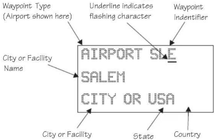
text_image
Waypoint Type (Airport shown here) Underline indicates flashing character Waypoint Indentifier City or Facility Name AIRPORT SALE SALEM CITY OR USA City or Facility State Country
- When you have entered the waypoint name, press ENTER.
Change Lat/Lon Reference Position
- Set the latitude and longitude coordinates near to your current position. After setting the Reference Waypoint, the first character of the Reference Position Lat/Lon will flash.
PPOS: 44°54.46H
199059-684
KEF HPT: CHD?

- Change the character with the SMALL knob. Turn the LARGE knob to move to each character of the Lat/Lon position and change it with the SMALL knob.
Ppos: 44°54.46N
100 100 100 100 100 100 100 100 100 100 100 100 100 100 100 100 100 100 100 100 100 100 100 100 100 100
ENTER
- Enter the Lat/Lon position, then press ENTER.

ENTER
- After entering the Seed Position, you will be prompted next to clear the active flight plan. Choose Yes or No with the SMALL knob. Press ENTER to continue normal operations.
CLEAR ACTIVE FLIGHT PLAN NO?
IFR Output Tests
A series of tests covering connections for IFR flight are tested if your Apollo GX has been installed and configured for IFR flight.
STARTING THE OUTPUT TESTS
After the completion of all tests the Apollo GX will start normal navigation operation.
CDI Output Tests
The CDI (Course Deviation Indicator) outputs are tested first. Each of the following displays is shown for two seconds, during which the external CDI needle should be driven as indicated by the display, which is up to the user to verify.
QIDS TESTS
0.21.14 0.000000 0.000000 0.000000 0.000000 0.000000 0.000000 0.000000 0.000000 0.000000 0.000000 0.000000 0.000000 1.1.1.14 1.1.1.14 1.1.1.14 1.1.1.14 1.1.1.14 1.1.1.14 1.1.1.14 1.1.1.14 1.1.1.14 1.1.1.14 1.1.1.14 1.1.1.14 2.3.2.26 2.3.2.26 2.3.2.26 2.3.2.26 2.3.2.26 2.3.2.26 2.3.2.26 2.3.2.26 2.3.2.26 2.3.2.26 2.3.2.26 2.3.2.26
CDI tests and display screens are provided for CDI Full Right, CDI Half Right, CDI Centered, CDI Full Left, and CDI Half Left.
TO/FROM Flag Output Tests
The To/From Flag outputs are tested next. Each of the following displays is shown for three seconds, during which the external To/From flag should be driven as indicated by the display, which is up to the user to verify.
TOMFROM FLAG
To
To/From Flag tests and display screens are provided for the To, From, and Off conditions.
Nav Valid and Nav Super Flag Tests
The Nav Valid and Nav Super Flag outputs are tested next. Each of the following displays is shown for three seconds, during which the external Nav Valid and Nav Super flags should be driven as indicated by the display, which is up to the user to verify.
GX55
MFW WALID FLAG
Nav Valid and Super Flag tests and display screens are provided for the Flagged and Not Flagged conditions.
VDI Output Tests (GX50 and GX60 only)
VDI (Vertical Deviation Indicator) outputs are tested next. Each of the following displays is shown for two seconds, during which the external VDI needle should be driven as indicated by the display, which is up to the user to verify.
0.00 0.01 0.02 0.03 0.04 0.05 0.06 0.07 0.08 0.09 0.10 0.11 0.12 0.13 0.14 0.15 0.16 0.17 0.18 0.19 0.20 0.21 0.22 0.23 0.24 0.25 0.26 0.27 0.28 0.29 0.30 0.31 0.32 0.33 0.34 0.35 0.36 0.37 0.38 0.39 0.40 0.41 0.42 0.43 0.44 0.45 0.46 0.47 0.48 0.49 0.50 0.51 0.52 0.53 0.54 0.55 0.56 0.57 0.58 0.59 0.60 0.61 0.62 0.63 0.64 0.65 0.66 0.67 0.68 0.69 0.70 0.71 0.72 0.73 0.74 0.75 0.76 0.77 0.78 0.79 0.80 0.81 0.82 0.83 0.84 0.85 0.86 0.87 0.88 0.89 0.90 0.91 0.92 0.93 0.94 0.95 0.96 0.97 0.98 0.99 1.00
15 - 30 31116. 301116. 301116. 301116. 301116. 301116. 301116. 301116. 301116. 301116. 301116. 301116. 301116. 301117. 301116. 301116. 301116. 301116. 301116. 301116. 301116. 301116. 301116. 301116. 301116. 301116. 32
Start Up Displays
VDI tests and display screen are provided for VDI Full Up, VDI Half Up, VDI Level, VDI Full Down, and VDI Half Down.
VDI Valid and VDI Super Flag Tests (GX50 and GX60/65 only)
The VDI Valid and VDI Super Flag outputs are tested next. Each of the following displays is shown for three seconds, during which the external VDI Valid and VDI Super flags should be driven as indicated by the display, which is up to the user to verify.
VDI VALID FLAG AND SUPER FLAG -FLAGGED-
VDI Valid and Super Flag tests and display screens are provided for the Flagged and Not Flagged conditions.
External Annunciator Lamp Tests
The external lamp outputs are tested next. The external lamps which are driven by the Apollo GX GPS Navigation Equipment include the message lamp, VFR lamp, parallel track lamp, approach lamp, Approach Active (GX50/60), and OBS/Hold (GX50/60). The lamps are all flashed on for one second and off for one second a total of three times, during which it is up to the user to verify that the external lamps which are connected are working.
EXTERNAL LAMPS FLASH ALL LAMPS ON
EXTERNAL LAMPS FLASH ALL LAMPS OFF
Screen Test
A full visual display test on each line of the display and all of the annunciators is run next, preceded for two seconds by the following screen.
STARTING DISPLAY TEST...
The visual display incrementally lights groups of pixels on the electroluminescent display.
Checking GPS Signal Strength
The unit shows the GPS signal strength screen in the GPS Sensor function. Make it a habit to check this screen to make sure that the unit is properly tracking visible satellites before you fly. The Apollo GX requires signals from at least four satellites to calculate a 3D position fix (Lat/Lon and GPS altitude). More details are available in the GPS Sensor part of the System section of this manual, see page 17.
SYS

ENTER
- Press SYS and turn the LARGE knob to display the GPS Sensor function. Press ENTER.
GPS SENSOR
- The GPS Health page is shown if GPS information is received. The GPS number and dimension (2D, 3D, or no position), number of healthy, and number of visible satellites are shown.
GPS 3D POSITION
HEALTHY SATS 24
VISIBLE SATS 0
Start Up Displays

- Turn the SMALL knob to view the GPS Satellites Used for the Position fixes page.
GPS SV's FOR FIX 31, 27, 26, 19, 07, 02

- Turn the SMALL knob again to view the GPS Satellite Status, Elevation, Signal Strength (SIG), and Azimuth page. Turn the SMALL knob to view information about each available satellite. The status will initially display as "SRCH" to indicate that it is searching for the satellite. After locking onto the satellite signal, the status will display as "DATA."

SV16 STATUS SRCH ELE 11° SIG 000 AZIMUTH 039°
Acquiring Satellite
SV24 STATUS DATA ELE 74° SIG 123 AZIMUTH 132°
Locked on Satellite

Note
The GPS antenna must be able to "see" each satellite it is tracking. If a satellite is "shaded" by the wing or fuselage during a turn, it may temporarily lose track of that satellite. If this happens, or if the geometry of the satellites available is poor, Nav information will temporarily not be available.
Flight Simulator
Your Apollo GX is provided with a Flight Simulation program that allows you to “fly” your unit by simulating the speed and altitude. This section describes the procedures used to run the Flight Simulator. You may operate the Flight Simulator in the cockpit or in your home to familiarize yourself with the operation of the Apollo GX.
About the Flight Simulator
The Flight Simulator is programmed into your Apollo GX at the factory. The Flight Simulator is activated during start up by pressing the NAV key while you turn the power switch on.
The Apollo GX “asks” you to enter a ground speed and altitude each time the Flight Simulator is started. This speed and altitude information will remain constant throughout the simulation. The Apollo GX uses a simulated GPS sensor to provide position, altitude, speed, and course information. As no external sensors are connected while the simulation is running, no information is displayed about external sensors. The simulated altitude and speed does not change while the Flight Simulator is running.
The Apollo GX uses the position of the first FROM waypoint in the Active flight plan as the initial position and simulates flight along the desired track to each successive TO waypoint. While “en route,” the Apollo GX generates updated navigation information and alert messages consistent with the simulated flight path. When the Apollo GX “arrives” at the final waypoint of your flight plan, it stops waypoint sequencing. The Apollo GX continues to simulate flight past the waypoint and provides bearing and distance information to the last TO waypoint. The simulated flight will only fly direct between waypoints, so it will not follow a DME-Arc on the Map display.
Removing and Replacing the Apollo GX
The following procedure is used to remove the Apollo GX so you can operate it at a location of your choice. . While inserting or removing the GX, Do not exert excessive turning force at the end of the cam lock travel or the unit may be damaged.
- Remove the Apollo GX from the front panel of your aircraft. Use the 3/32" hex driver included with installation kit (p/n 998-0048). Insert the hex driver into the hole at the top, center of the front panel of the GX-series. Turn the hex driver counterclockwise to loosen the connecting screw.
- Pull the Apollo GX out of its mounting tube.
- Connect the GX-series Power Cable Assembly (p/n 500-4027 for the GX55 or 500-4026 for the GX50/60) to the connector(s) on the back of your Apollo GX. Connect the cable to a power supply that provides 10 to 40 VDC @ 1A or greater. Attach the black wire to ground and red wire to positive. A suitable power supply may be purchased at an electronics or auto supply retailer.
Note
Operation of the GX60/65 transmitter is not permitted in a residential or industrial environment without an appropriate FCC license. Operation of the GX50/60 with a serial port connected to a computer is not currently authorized under FCC part 15 regulations.
- Replace your GX into the tube carefully. Position the cam lock as shown below. The front lobe of the cam should be vertical. The cam lock mechanism should be fully unscrewed (turned counter-clockwise). Slide the unit into the frame. Turn (clockwise) and carefully hand-tighten (4 in-lb max.) the cam lock mechanism using only the 3/32" hex driver provided in the installation package. Using a larger tool than the one provided makes it easy to exceed the allowable torque on the cam lock resulting in damage to the unit. The unit will be pulled into the frame securing the unit and the connectors will fully engage. Do NOT overtighten. The back of the bezel must only be flush to the mounting tube. If the cam

text_image
REAR CAM DOWN FRONT CAM UP BEZEL POSITION CAM FULLY TO REAR BEFORE INSERTIONlock is hard to turn or the unit does not seat fully, the unit is probably binding and the mounting tube should be checked.
Starting the Flight Simulation
The following procedure is used to start the flight simulation. It is recommended that you have a data card properly inserted into the data card slot so you can use the appropriate functions.
NAV
-
Turn on the power for the power supply. Press and hold down the NAV key as you turn on the power for the Apollo GX.
-
The Apollo GX will run its database and memory tests. The display will then show that it is ready to start the Flight Simulator.
FLIGHT SIMULATOR NOT FOR FLIGHT PRESS SEL
SEL

- Press SEL to start the Flight Simulator. The default ground speed and altitude will be displayed. The ground speed value will flash. Turn the SMALL knob to display the desired ground speed. Speed values are changed in 10 kt increments.
SIMULATOR SETUPS GR SPEED 100 KTS ALTITUDE 1000FT

- Turn the LARGE knob to make the altitude value flash. Turn the SMALL knob to display the desired altitude. Altitude values are changed in 100 ft increments.
SIMULATOR SETUPS GR SPEED 170KTS ALTITUDE 4500 FT
ENTER
- Press ENTER to enter the displayed ground speed and altitude values and start the flight simulation.

ENTER
- You will be prompted to use or clear the previous Flight Plan. Turn the SMALL knob to choose Yes or No. Press ENTER. If you do nothing, the Apollo GX will automatically retain the previous Flight Plan and switch to the Nav function. The Apollo GX will go to the Nav function and a simulated GPS sensor begins tracking your position from the first From waypoint in the Active flight plan.
CLEAR ACTIVE FLIGHT PLAN? YES
Flight Simulator Operations
Once you've started the flight simulator, you may practice the various operating procedures, such as activating flight plans, entering Direct-To courses, and inserting/deleting/changing waypoints in the Active flight plan. The simulator is also useful for planning purposes; you may create and edit flight plans in the comfort of your office or home. Changes made to flight plans and waypoints while the simulator is running are retained when the Apollo GX is reinstalled in the aircraft.
Note
The simulator does not replicate all procedures exactly. After you select a OBS DTK, the simulator will immediately place the aircraft location in line with the inbound course, bypassing a procedure turn or DME Arc.
While the heading follows the DTK on turns and arcs, the simulator aircraft will actually move in a straight line.

Troubleshooting
Or, what to do when nothing works!
This section contains information to troubleshoot your Apollo GX product when improper operation is observed. The following table lists possible problems you could encounter while operating the unit. Examine the possible causes of the problem and take the action listed to correct the trouble. If you cannot correct the problem, contact your dealer. If your dealer is unavailable, contact the II Morrow factory at the address and phone number listed.
Contacting the Factory
If efforts to resolve the problem fail, contact your dealer or the factory weekdays from 8:00 A.M. until 5:00 P.M. Pacific time for technical assistance. The II Morrow technical service staff will gladly assist you.
Please have the following information ready:
- System configuration (products, antennas, mounting locations, etc.)
• Model No., part number, and serial number - Software versions
• Description of the problem
• Efforts made to isolate/solve the problem
• Computed Lat/Lon position shown on your Apollo - Local time, UTC time, and date
II Morrow Inc.
Technical Service Department
2345 Turner Road S.E.
Salem, OR 97302 U.S.A.
U.S.A. Toll Free 800-525-6726
Canada Toll Free 800-654-3415
FAX (503) 364-2138
International (503) 391-3411
To Ensure Trouble Free Operation
Avoid high cockpit temperatures when the aircraft is not in use. Extreme heat shortens the life of any electronic equipment. Periodically check all antenna, power, and ground connections.

Caution
DO NOT clean the face plate with chemical cleaning agents, solvents, or harsh detergents. A soft cloth may be used to clean the face plate. DO NOT wax or paint the antenna.
Battery Replacement
The Apollo GX memory is maintained by a lithium battery. The expected service life of this type of battery is from four to six years. This is not a user replaceable item. The lithium battery must be replaced by the factory, an authorized dealer, or service center.
If You Have A Problem
Please read the instructions again for the desired function.
If You Are Unable To Correct The Problem
Record as much information as possible, such as where and when the problem occurred, symptoms, and your actions. Record the position sensor data (displayed in SYS mode) for ALL satellites (GPS) and call your II Morrow dealer, Service Center, or the factory. The technician MUST have this information to help you solve the problem.
Problem Possible Cause Action
| Unit does not power on | Open in power supply circuit | Check circuit breaker - reset if necessary |
| Faulty electrical wiring or connection | Contact your dealer to perform electrical system test |
Problem Possible Cause Action
| No GPS signal reception | Obstructed signal path | Move aircraft out of hangar or away from buildings to provide an unobstructed view of the sky for the antenna |
| Incorrect seed position, time, or UTC differential entered | Check these settings, if necessary in the System Functions | |
| If using a wrong antenna: faulty external antenna, wiring, or connections | Contact your dealer to check the antenna and other wiring | |
| Interference Check for GPS L1interference sources. Contact your dealer or Il Morrow tech support. | ||
| MSG light stays on after power-on. Displayed message is: IN USE SENSOR CANNOT COMPUTE Lat/Lon | The In-Use position sensor is not able to calculate a position | Check for obstructions and connections to the antenna.The GPS engine may need to be reset. |
| No User waypoints show up on the Map display or the Nearest waypoint list | Runway Limits are set for a value that is too large | Reset the Runway Limits value, see page 3-12 |
| Waypoint sequencing is erratic | Direct-To entry option setting may not be correct | If you are flying Direct-To, the option should be set to “May Clear”, see page 7-9 |
Problem Possible Cause Action
| Search for nearest waypoints reveals too few or wrong types of waypoints | Incorrect selection of waypoint types to show after searchRunway Limits are set for a value that is too large | Check "Airspace Setup" function and verify that the desired waypoint type to search is "ON", see page 4-10Check the "Identifier and Waypoint Type" section of the Moving Map function on page 6Check the Runway Limits for too large a value, see page 3-12 |
| Position fix seems inaccurate | Wrong seed position | Re-enter seed position |
| Bearing & distance values appear to be wrong | A mistake may have been made in entering the Lat/Lon position for a User waypoint, or the wrong waypoint was selected | Verify that the position of the User waypoint is accurateCheck the FROM and TO waypoints |
| Wrong bearing and track values | Incorrect magnetic variation entered | Check Magnetic Var option - select "Automatic" or enter correct value, see page 7-7 |
| Display blinks Voltage | applied to system is too low | Check avionics power bus |
| No altitude info Altitude | de information device was not configured during installation | Check installation configuration |
| No altitude info | No power to the altitude encoder | Check altitude encoder power |
GPS Navigation
GPS Overview
The Global Positioning System (GPS) is a constellation of 24, or more, satellites in six orbit lanes 10,898 nautical miles above the earth at an inclination angle of about 55 degrees from the equator. Each satellite orbits the earth twice in 24 hours.
The GPS was developed and the satellites launched by the U.S. Department of Defense with the original intent of supplying highly accurate position fix information for military applications. In recent years, commercial applications for the information provided by this system have steadily increased in the civilian sector. Some of the more popular civilian uses of the system include surveying and position fix data recording for civil engineering applications, and a broad range of marine, aviation, and terrestrial navigation applications.
While orbiting the earth, each GPS satellite transmits complex streams of data containing the operational status and orbital location of all the satellites in the system. The Apollo GX receives this data stream and
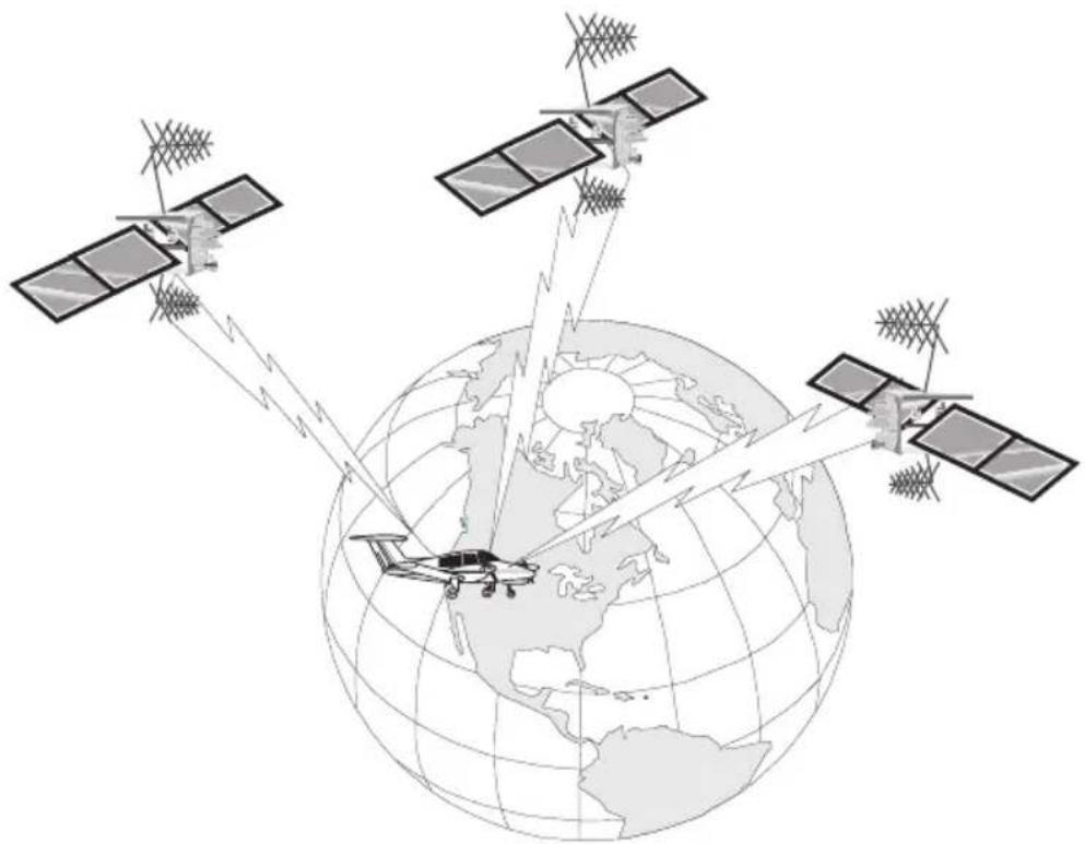
natural_image
Illustration of satellites orbiting Earth with ground stations, no text or symbols presentGPS Navigation
processes the information to determine which satellites are “visible” to the receiver’s antenna. With this determination made, the receiver chooses satellites to calculate a position fix. Using information transmitted from three or more satellites, the unit can calculate latitude and longitude (usually abbreviated Lat/Lon); with four or more satellites, GPS altitude can also be calculated.
GPS System Accuracy
The GPS allows a high degree of position fix accuracy. The system can produce a position fix accurate to within less than one meter under ideal conditions. Due to concern for national security, the U.S. Department of Defense introduces constantly changing errors to the transmitted satellite data to degrade the accuracy of the system. Called Selective Availability, this practice limits GPS position fix accuracy to about 100 meters, although the relative position of the satellites to one another, their elevation above the horizon, and other factors can also affect accuracy of the position fix. Under optimal conditions, accuracy can improve to within 10 meters. GPS position fix accuracy is not affected by atmospheric conditions.
GPS altitude is based on a mathematical model of the shape of the earth, the WGS-84 ellipsoid. Including intentional degradation, GPS altitude may differ from barometric altitude by several hundred feet.
Glossary
A Altitude (GPS ALT): Altitude, as calculated by the
Apollo GX, based upon a mathematical model of the earth's surface curvature. A substantial difference between this altitude value and altitude referenced to sea level may exist.
Altitude Assist: An aid that provides guidance in descending from one altitude to another. See the Altitude Assist description on page 3-14 for details.
Almanac: Data transmitted by a GPS satellite including orbit information on all satellites, clock correction, and atmospheric delays.
ARC: A DME arc terminator with the preceding flight plan leg is described as an arc to this waypoint. An ARC waypoint may follow another ARC waypoint.
ATC Ring: On the map display, an artificial ring five nm in diameter is drawn around airports that have a control tower.
Automatic Terminal Information Service (ATIS):
Recorded information about weather and other conditions at an airport, periodically updated when conditions change.
Autonav: The function that allows you to set the GX to scroll automatically through selected navigation displays.
AWOS: Automated Weather Observation System.
AWOS reports wind speed and direction, temperature and dew point, cloud height and cloud cover, atmosphere pressure, and precipitation.
Azimuth: an arc, as measured clockwise from true or magnetic north.
B Baro Altitude: Barometric altitude (pressure altitude corrected for local altimeter setting). This altitude should match the altitude displayed on your aircraft altimeter.
Bearing (BRG): The direction to any point, usually measured in degrees relative to true or magnetic north. The direction from your present position to your destination waypoint.
C CF: Final approach course Fix. This waypoint type is used when necessary to define a course to the FAF - all VOR DME approaches require a course fix waypoint. A code appended to a waypoint in the database that may not appear on a published map.
Circular Error Probable (CEP): As applied to GPS position fix accuracy, the radius of a circle inside of which there exists a 50 percent chance of being located.
CNTR: Area Control Center frequency.
Constellation: A group of stars or objects, such as GPS satellites, in the heavens.
Coordinates: Values for latitude and longitude that describe a geographical point on the surface of the earth.
Course: The planned direction of travel in a horizontal plane.
Course Deviation: A measurement of distance left or right from the desired course of travel.
Course Deviation Indicator (CDI): A graphic indicator of course deviation typically shown as a graduated horizontal bar with an icon indicating the deviation distance left or right of course.
Course Intercept: Similar to an arrival alert, arrival is related to a course or radial to a point. When flying an
arc during an approach, the arrival alert is issued when the aircraft is 1 nm/100 kts of intercepting the inbound course. When Vector to Final is selected, or you are executing a procedure turn at the FAF, the course intercept alert occurs when the aircraft has a Track Angle Error ≤45^ and the cross track deviation is ≤1 nm.
Cross Track Deviation: The distance that your are away from your intended course.

text_image
FROM WPT Distance Off Track North TO WPTCTAF: Common Traffic Advisory Frequency.
D Database: A collection of data structured in such a way as to allow quick and convenient access to any particular record or records. The Apollo GX contains a built-in database of waypoints and waypoint information. Users may add waypoints to this database.
Declination: The difference between True North and Magnetic North. A magnetic declination of 19^ E means that Magnetic North is 19^ E of True North.
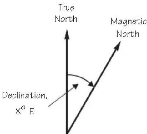
text_image
True North Magnetic North Declination, X° EDeclutter: The ability to select the waypoint types and symbols that are displayed on the moving map.
Degree: 1/360th of a circle.
Departure: The first waypoint in the active route.
Desired Track (DTK): The desired course of navigation between a point of origin (FROM) and a destination (TO) waypoint.
Destination: The last waypoint in the active route.
Dilution of Precision (DOP): A merit value for the calculated position based on the geometrical configuration of the satellites used; 3 is considered good, greater than 7 is considered poor. Also called Precision Dilution of Precision or PDOP.
Direct-To: The function or procedure that directs you from your present position to the designated TO waypoint.
Distance: A measure of interval in space. Also referred to as range.
DME: Distance Measuring Equipment
Drift: Displacement from the intended course of travel.
E Elevation: The angle of a GPS satellite above the horizon.
Emergency Search: The function that allows you to immediately navigate to the nearest airport in the case of an emergency.
Ephemeris: A list of accurate positions or locations of a celestial object as function of time.
Estimated Time of Arrival (ETA) - The estimated time of arrival at the TO waypoint in UTC time using a 24 hour clock.
Estimated Time En route (ETE) - The estimated time from your present position to the TO waypoint.
F FAF: Final Approach Fix.
FDE: The Fault Detection and Exclusion column refers to the ability to identify and exclude a faulty satellite and still have suitable satellite geometry at that position.
FF: Final Approach Fix. A code appended to a waypoint in the database that may not appear on a published map.
Fix: A geographical location determined by either visual reference or by electronic navigation aids.
Flight Time: Flight Time shows the elapsed time in hours and minutes (00:00 to 99:59) from departure. If the Flight Timer is not started the value will be replaced with dashes. The Flight Timer options are set in the System Functions (see page 7-8).
Flight Plan: A series of two or more waypoints.
FSS: Flight Service Station.
G GDOP: Geometric Dilution of Precision. The relationship between errors in receiver position and time and in satellite range.
Global Positioning System (GPS): Also known as NAVSTAR. A constellation of satellites launched by the U.S. Department of Defense into six orbit lanes (four satellites per plane) at an altitude of 10,898 nm above the earth.
Greenwich Mean Time (GMT): See Universal Time Coordinate (UTC).
Ground (GRND): Ground communication frequency
Ground Speed (GS): Speed of travel across the ground. In aviation, the relation between ground speed and air speed is affected by the prevailing winds.
H HDOP: Horizontal Dilution of Precision. See Dilution Of Precision.
Hold: Waypoint sequencing is disabled or suspended. A hold may be automatically or manually activated. This should not be confused with a “holding pattern.” Pressing the OBS/HLD key suspends waypoint sequencing.
IAF: Initial Approach Fix.
Identifier: A name, typically abbreviated, assigned to a waypoint. The identifier may consist of numbers and alpha characters, up to six in length. For example, the airport identifier for Los Angeles International Airport is LAX.
IFAF: Initial and Final Approach fix. A combined Initial and Final approach Fix with no intermediate waypoints.
IFR: Instrument Flight Rules
Intersection (INT): A point defined by any combination of courses, radials, or bearings of two or more navigational aids.
K Knot (kt): A unit of speed equal to one nautical mile per hour.
L Latitude (Lat): Any line circling the earth parallel to the equator, measured in degrees, minutes, and seconds north and south of the equator.
LFAC: Landing FACility.
Longitude (Lon): Any line from the north to the south pole, measured in degrees, minutes, and
seconds of a circle, east or west of the Prime Meridian (Greenwich, England).
M MA: Missed Approach Point. A code appended to a waypoint in the database that may not appear on a published map.
Magnetic North: The region, some distance from the geographic north pole where the earth's magnetic lines concentrate. A magnetic compass points to the magnetic north.
Magnetic Variation (Mag Var): The angle between the magnetic and true north. At various points on the earth it is different due to local magnetic disturbances. It is shown on charts as isogonic lines marked with degrees of variation, either east or west. These degrees must be added to or subtracted from the true course to get the magnetic course. (Easterly variations are deducted, and westerly variations are added.) The Apollo GX automatically sets magnetic variation to 0 degrees at positions above 70 degrees north or south latitude. See Declination.
MAHP: Missed Approach Hold Point.
MAP: Missed Approach Point.
Map Datum: A mathematical model of the earth used for the purpose of creating navigation charts and maps. The Apollo GX uses the WGS-84 map datum.
MESA: Minimum En route Safe Altitude is the highest MSA for every point between the aircraft present position and the “TO” waypoint with a 5 nm buffer around the course.
Meter (m): A metric distance measurement equal to 39.37 inches.
Minute: 1/60th of a degree.
MSA: Minimum Safe Altitude. The elevation of the highest obstruction near the aircraft plus a 1,000 or 2,000 foot buffer added for safety. In non-mountainous terrain, a 1,000 foot buffer is added. In mountainous terrain, a 2,000 foot buffer is added. The result is rounded to the nearest 100 feet.
N Nautical Mile (nm): A distance measurement equal to 6,076 feet, or 1.15 statute mile. One nautical mile is also equal to one minute of latitude.
NAVSTAR: The name given to GPS satellites formed from the acronym for NAVigation System with Time And Ranging.
Non-Directional Beacon (NDB): A low frequency/medium frequency navigation aid sending non-directional signals that can be used for navigation.
OBS: Omni-Bearing Selector.
P Parallel Track Offset: A course that is parallel to the designated course, but offset to the right or left by a given distance.
PDOP: Position Dilution of Precision. See Dilution of Precision.
PRN: GPS satellite Pseudo-Random Numbers are used to uniquely identify satellites. This is different than the SVN (Space Vehicle Number, or satellite serial number). When excluding satellites from the RAIM Prediction, use the PRN number found on the NOTAMs and NANUs, not the SVN.
R Radial: Any of the 360 magnetic courses from a VOR or similar navigational aid, beginning at the navigational aid and proceeding outward in a straight line.
RAIM: Receiver Autonomous Integrity Monitoring. A method of predicting possible system accuracy errors that may be caused by bad satellite data. The RAIM algorithm requires that more satellites are available and usable than required for a normal GPS position fix.
Range: The distance from the present position to a destination waypoint.
Relative Bearing Indicator: The Relative Bearing Indicator is an arrow next to the Bearing value that indicates an approximate bearing to a waypoint or airspace relative to the aircraft's current track when your current ground speed is more than 5 knots.
RW: Runway Fix. A code appended to a waypoint in the database that may not appear on a published map.
S Second: 1/60th of a minute of a degree.
Seed Position: A latitude and longitude position fix approximately equal to the current position that the Apollo GX uses to determine the location of available satellites from which signals may be received.
Selective Availability (SA): The degradation of accuracy of GPS position fix data by the United States Department of Defense for civilian use.
Space Vehicle (SV): A GPS satellite.
Statute Mile: A distance measurement equal to 5,280 feet or 0.87 of a nautical mile.
T Three-dimensional (3D) Position Fix: A position fix defined by latitude, longitude, and altitude.
Track (TRK): The imaginary line that the flight path of an airplane makes over the earth.

text_image
North TO WPT TRK DTK Present Position FROM WPT Track Angle Error (Tae)Track Angle: The angle of your actual direction of travel. Track angle is computed using the magnetic variation at the Present Position.
Track Angle Error (TAE): The difference between the Desired Track and the Track Angle (Dtk - Trk = Tae). A letter is shown next to the Track Angle Error value showing the direction of error in reference to the current Track.
True North: Geographic north, at the earth's north pole.
Tower (TWR): Airport tower communication frequency.
U UNICOM: The radio frequencies assigned to aeronautical advisory stations for communication with aircraft. Unicoms may provide such airport information as active runway, wind direction and velocity and other conditions of importance to pilots.
UTC (Universal Time Coordinate): Greenwich Mean Time, or the time at the Prime Meridian in Greenwich, England. Also referred to as Zulu time.
UTC Differential: The difference in time between that at the present position and UTC.
UTM (Universal Transverse Mercator map projection system): Also known as Military Grid Coordinates, the UTM grid consists of 60 north-south/east-west zones, each six degrees wide in longitude.
V VFR: Visual Flight Rules.
VOR: Very High Frequency Omni-directional range. A navigational aid that transmits signals such that a receiver can indicate its current radial or bearing from the transmitter.
VHF: Very High Frequency. The range of frequencies between 30 and 300 MHz.
VNAV: Vertical Navigation. See Altitude Assist.
W Waypoint: A navigation fix used in area navigation and defined by latitude and longitude coordinates.
Notes
Jndex
A
Abbreviations....10-4
Access database....5-3
Activate flight plan . . . . . . 6-14
Air pressure....7-20
Air speed ..... 7-20 - 7-21
Air temperature ..... 7-20 - 7-21
Airport elevation ..... 5 - 6
Airport frequency . . . . . . . . 5 - 6
Airport Info. 5 - 1
Airspace
Alternate approach ..... 9-35
Altimeter. 7-20
Altimeter Setting . . . . . . . 3-14
Altitude assist....9-26
Altitude Assist. . . . . . . . . . 3-14
Missed Approach Point · · 9-12
Approach operation ..... 9-30
APT smart key . . . . . . . . . 1 - 6
Arc assist....3-23
Arc Assist. 3-24
Arrival alert. . . . . . . . . . . . 8 - 9
Arriving at TO wpt ..... 8-9
ATC ring. 4-12
Auto descent. . . . . . . . . . 3-17
Auto store frequency . . . . . . 10-6
Auto-Descent. . . . . . . . . 3-18
Autonav. . . . . . . . . 3-2,7-1,7-4
Autopilot. 3-37
B
Bar graph . . . . . . . . . . . . . 3 - 5
Baro Measure....7-14
Baro-aiding....9-31
Basic Grid . . . . . . . . 4-16, 4-18
Battery replacement ..... 13-2
Battery voltage....8-14
Bearing....3-4
Brightness, Display ..... 7-14
Burn rate. 7-22
C
Cancel approach. . . . . . . . 9-15
C D I . . . . . . . . . 3-5, 3-32, 6-20
CDI reverse sensing ..... 9-22
Change approach....6-22
Cleaning....13-2
Clear exclusion list ..... 9-35
Clear flight plan wpts ..... 6-17
Close....4-11,8-3
Close altitude....8-
Com
See alsoFlight plan comments
See alsoWaypoint comments
Continue flight plan ..... 6-21
Controls....1-
Conventions....1-iv
Copy flight plan . . . . . . . . 6-16
Countdown timer ..... 3-22, 8-14
Course intercept ..... 8-10
Create User waypoint ..... 4-29
Creeping Line Pattern ..... 4-23
Cross track distance. . . . . . . 3 - 6
Crossing FAF....9-12
Current time....2-1
Customizing Nav pages ..... 7 - 2
D
Database....5-1-5-16
Database expired. . . . . . . . 8-13
Database invalid. . . . . . . . 8-13
Database message ..... 11-5
Database test. . . . . . . . . . . 11-4
Datacard....5-16
Date and Time ..... 7-11
Delete flight plan . . . . . . . 6-18
Density altitude ..... 7-21
Descent rate. 3-17
Description
Desired track....3-6
Diamond....3-1
Direct-To. 2-7, 3-31 - 3-32, 6-9, 7-8, 9-18
Distance off track....3-5
3 Distance to waypoint ..... 3-25
DME Arc .. 3-24, 8-11 - 8-12, 9-26, 9-63, 9-87, 12-1
D T K U p. . . . . . . . . . . . . . . 4 - 5
Duplicate names. . . . . . . 2-4, 5-4
E
Edit owner information. . . . . 7-16
EEPROM....11-4
Elevation....5-6
E-Mail. 1-ii
Emergency approach ..... 9-35
Index
Emergency channel ..... 10-8
Emergency search ..... 3 - 9
Empty TO waypoint....8-4
En route operation ..... 9-30
Enable approach ..... 6-23, 9-8
Encoder altitude. . . . . . . . 3-15
Encoding altimeter ..... 7-20
Ending Altitude ..... 3-18
Enroute. 9-1, 9-5
Error messages....8-3
Estimate ground speed . . . . . 6-16
Estimated fuel flow ..... 6-17
Estimated time enroute 3-4, 6-7 - 6-8
Estimated time of arrival . . 3-9, 6-7
ETA to waypoint ..... 3-25
ETE to waypoint ..... 3-25
Examples
Find waypoint....2-1, 2-6
Flight plan . . . . . . . . 6-1 - 6-26
Flight time. . . . . . . . . 3-9,7-8
Flip/Flop key . . . . . . . . . . . 1 - 8
Frequency abbreviations . . . . 10-4
From. 6-19
FROM waypoint. . . . . . . . 3 - 6
From/To/Next. . . . . . 3-26, 3-29
From-To distance ..... 3 - 6
Fuel. . . . . . . . . . . . . . 5 - 7 - 6 - 8
Fuel endurance....7-22
Fuel flow. 7-20
Fuel info . . . . . . . . . . . . . 7-22
Fuel Measure . . . . . . 7-13, 7-24
Fuel range....7-22
Fuel sensor. 7-20
Fuel used. 7-22
Fuel warning. . . . . . . . . . 7-23
Fuel/Air Data sensor ..... 7-20
G
Glide path . . . . . . . . . . . 3-17
Glide slope . . . . . . . . . . . 3-17
Glossary . . . . . . . . 15-1 - 15-12
G P S . . . . . . . . . . . . 7-19, 14-1
Communication failure ···· 8-5
Health···7-17, 11-11
Signal Strength···7-18
Grid Line Display ..... 4-15
Ground speed....3-7
GX50 description ..... 1 - 2
GX55 description ..... 1 - 2
GX60 description ..... 1 - 2
H
Headphone level . . . . . . . 10-12
Heat....13-2
Help!....13-1
History of Revisions ..... 1-ii
Hold. . . . . . . . 3-19, 3-30, 6-18
Hold altitude....3-16,8-8
Hold buffer....3-16
Holding at Towpt ..... 8-11
Holding patterns. . 6-19, 9-24 - 9-25
H S I . . . . . . . . . . . . . . . 3-17
I
I A F....9-10
IFR output tests ..... 11-8
II Morrow....13-1
ILS runway . . . . . . . . . . . . 5 - 6
Indicated air speed ..... 7-21
Info ..... 3-14, 5-1, 5-5, 6-23, 8-3
Info 28,37,40,60,62,98....10-6
INSIDE....8-4
INT smart key . . . . . . . . . 1 - 6
Intercom....10-8
Intercom level ..... 10-11
Intercom squelch. . . . . . . . 10-10
Intersection info 5 - 2
K
K e y. . . . . . . . . . . . . . . . . 1 - 4
A P T 1 - 6
Map waypoint keys ..... 1-6
Mark position ..... 4-28
May clear....7-9
May Clear. . . . . . . . . . . . . 2 - 7
Measurement units ..... 7 - 6
Memory failure ..... 8-13, 11-1
Memory loss or failure ..... 8-12
Memory test....11-2, 11-4
Message....8-1-8-14
Microphone....10-9
Minimum enroute safe altitude . 3-8
Minimum safe altitude ..... 3 - 8
Misc sensors ..... 7-20
Missed approach. . . . . . . . 9-13
Missed approach point . . . . 9-12
Monitor frequency ..... 10-3
Moving map....2-10
Multiple facilities ..... 5 - 4
See alsoDuplicate names
N
Nav page choices . . . . . . . . 7 - 5
Nav superflag tests ..... 11-9
Nav Valid flag tests ..... 11-9
Navigation....3-1,7-1
Nearest waypoint. . 2-6, 3-12 - 4-13, 5-9, 9-36, 10-6
Nearest waypoint search . . 3-9, 5-1
Never clear . . . . . . . . . . . . 7 - 9
Noise level . . . . . . . . . . 10-10
Non-volatile RAM test . . . . . 11-3
North Up. . . . . . . . . . . . . 4 - 5
NRST 1-2, 1-4, 2-6, 3-9 - 3-10, 3-12, 4-6, 4-13, 9-36, 13-3
NVRAM ..... 11-4
O
OBS ..... 3-35, 8-12, 9-18
Offset distance ..... 3-17
Ordering Information ..... 1-ii
O R I k e y . . . . . . . . . . . . . . . 1 - 7
Outside air temperature. . . . . 7-21
Owner information ..... 7-15
Owner message ..... 11-2
P
Parallel Line Pattern . . . . . 4-21
Parallel track. . . . . . . 3-19, 3-21
Recall frequency ..... 10-4
R E F k e y. . . . . . . . . . . . . . . 1
Reference position. . . . . . . 11-7
Reference Waypoint 3-10, 5-10, 11-6
Relative Bearing Indicator . . . . 3 - 3
Remove unit from aircraft . . . 12-2
Rename flight plan . . . . . . 6-15
Repeat approach. . . . . . . . 9-16
Replace unit in aircraft ..... 12-2
Reserve fuel....7-23
Rev Activate....6-15
Reverse flight plan. . . . . . . . 6-17
RF signal strength ..... 10-10
Right engine fuel . . . . . . . 7-23
RNAV....5-16,9-1
Route line. . . . . . . . . . . . 4 - 4
Route line key . . . . . . . . . . 4 - 4
R T E k e y . . . . . . . . . . 1-7,4
Runway info. . . . . . . . . . . . 5 - 7
S
Parallel Line Pattern · · · 4-21
Sectional Chart Grid · · · 4-19
Setting up a search pattern 4-32
Search around ref wpt. . . . . . 3-10
Sectional Chart Grid ..... 4-19
Seed Position ..... 11-5
Select a waypoint ..... 2-1, 2-3
Select different approach . . . . 9-17
Setting measurement units. . . . 7 - 6
Setting up a search pattern . . . 4-32
Sidetone level. . . . . . . . . 10-12
Skip....1-6, 11-1
Small knob....1-3
Software memory test ..... 11-2
Software version ..... 7-12
SOON....8-3
Sort waypoints 2 - 2
Special use airspace ..... 3-13
Specifications ..... 1 - 9 - 1-12
Speed....7-22
Squelch knob....1-3
Standby 3-20
Start up displays . . . . 11-1 - 11-12
Startup bypass ..... 11-1
Storing a waypoint....2-5
Stuck microphone ..... 10-9
Index
Sunset/Sunrise time ..... 5 - 8
Symbol
UTC time. . . . . . . . . 3-9, 11-5
UTM 7-4
T
Technical assistance. . . . . . 13-1
Terminal operation ..... 9-30
Tips. 6-26
T o 6-19
TO waypoint. . . . 2-4, 3-6, 4-1, 8-9
TO-FROM flag tests ..... 11-8
Total fuel. 7-23
Track angle....3-7
Track angle error ..... 3 - 7
Track History ..... 4 - 8
True air temperature ..... 7-21
True north....7-7
True wind direction. . . . . . 7-22
TSO C129 overlay. . . . . . . 9-77
Turn anticipation....3-36
Turn rate. 7-21
U
Underline. . . . . . . . . . . . 1-iv
Units. 7 - 6
Unload approach ..... 6-22
Update User Wpt ..... 5-12
US Grid Type ..... 4-15
User database memory failure . 11-3
User frequency ..... 10-7
User waypoint
Vector to Final. 9-27
Vertical deviation. . . . . . . 3-17
VNAV 3-14
Volume knob....1-3
VOR Info. . . . . . . . . . 3-39, 5-2
VOR smart key ..... 1-6
W
Waypoint
Waypoint alert....8-10
Weather channel ..... 10-7
Web Page . . . . . . . . . . . . . 1-ii
Wind direction. . . . . . . . . 7-22
Wind speed....7-22
X
X I T k e y . . . . . . . . . . . . . . 1 - 8

GARMIN®
© 2003 by Garmin AT, Inc.
2345 Turner Rd., S.E.
Salem, OR 97302
U.S.A.
Phone 503.581.8101
800.525.6726
In Canada 800.654.3415
FAX 503.364.2138
http://www.garminat.com
Part #560-0961-03b
August 2003
APOLLO