SM7C12N-3 - Security Camera Moog Videolarm - Free user manual and instructions
Find the device manual for free SM7C12N-3 Moog Videolarm in PDF.

User questions about SM7C12N-3 Moog Videolarm
0 question about this device. Answer the ones you know or ask your own.
Ask a new question about this device
Download the instructions for your Security Camera in PDF format for free! Find your manual SM7C12N-3 - Moog Videolarm and take your electronic device back in hand. On this page are published all the documents necessary for the use of your device. SM7C12N-3 by Moog Videolarm.
USER MANUAL SM7C12N-3 Moog Videolarm
© 2009, Videolarm, Inc. All Rights Reserved
natural_image
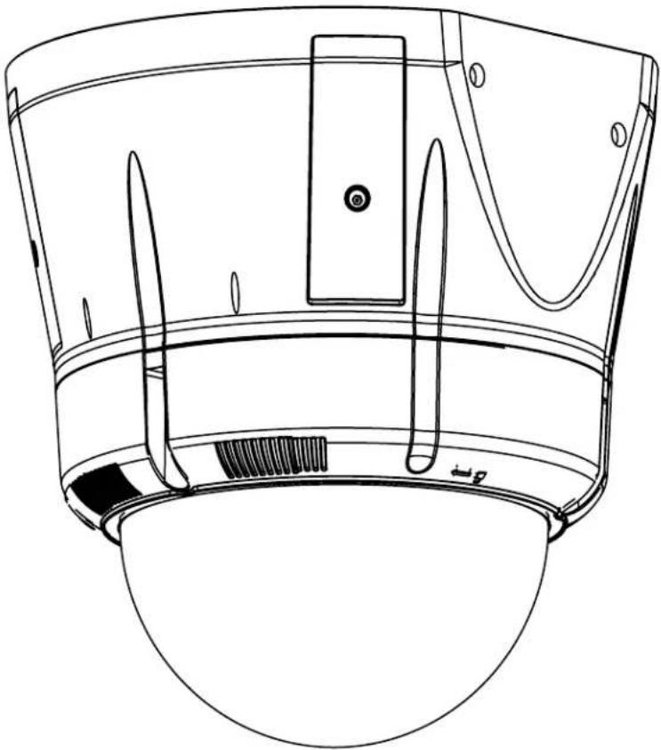
Technical line drawing of a mechanical component with no visible text or symbolsSM7CS-9, SM7C12S-9
SView™ Series
www.videolarm.com
Installation and Operation Instructions for the following models:
Before attempting to connect or operate this product, please read these instructions completely.

CERTIFIED
81-IN5391
07-09-2010
- Read Instructions - All the safety and operating instructions should be read before the unit is operated.
- Retain Instructions - The safety and operating instructions should be retained for future reference.
- Heed Warnings - All warnings on the unit and in the operating instructions should be adhered to.
- Follow Instructions - All operating & user instructions should be followed.
- Electrical Connections - Only a qualified electrician should make electrical connections.
- Attachments - Do not use attachments not recommended by the product manufacturer as they may cause hazards.
- Cable Runs - All cable runs must be within permissible distance.
- Mounting - This unit must be properly and securely mounted to a supporting structure capable of sustaining the weight of the unit. Accordingly:
a. Installation should be made by a qualified installer.
b. Installation should be in compliance with local codes.
c. Care should be exercised to select suitable hardware to install the unit, taking into account both the composition of the mounting surface and the weight of the unit. Be sure to periodically examine the unit and the supporting structure to make sure that the integrity of the installation is intact. Failure to comply with the foregoing could result in the unit separating from the support structure and falling, with resultant damages or injury to anyone or anything struck by the falling unit.
UNPACKING
Unpack carefully. Electronic components can be damaged if improperly handled or dropped. If an item appears to have been damaged in shipment, replace it properly in its carton and notify the shipper. Be sure to save:
- The shipping carton and packaging material. They are the safest material in which to make future shipments of the equipment.
- These Installation and Operating Instructions.
SAFETY PRECAUTIONS IMPORTANT SAFEGUARDS


CAUTION: TO REDUCE THE RISK OF ELECTRICAL SHOCK, DO NOT EXPOSE COMPONENTS TO WATER OR MOISTURE.
The lightning flash with an arrowhead symbol, within an equilateral triangle, is intended to alert the user to the presence of non-insulated "dangerous voltage" within the product's enclosure that may be of sufficient magnitude to constitute a risk of electric shock to persons.

The exclamation point within an equilateral triangle is intended to alert the user to presence of important operating and maintenance (servicing) instructions in the literature accompanying the appliance.
SERVICE
If the unit ever needs repair service, customer should contact Videolarm (1-800-554-1124) for return authorization & shipping instructions.
TECHNICAL SUPPORT
Videolarm has set-up a 24 hour technical support line for their customers.
24 HOUR TECHNICAL SUPPORT
1-800-554-1124
LIMITED WARRANTY FOR VIDEOLARM INC. PRODUCTS
VIDEOLARM INC. warrants this Product to be free from defects in material or workmanship, as follows:
PRODUCT CATEGORY
| All Enclosures and Electronics | Five (5) Years | Five (5) Years | ||
| Pan/Tilts | Three (3) Years | **6 months if used in autoscan | Three (3) Years | **6 months if used in autoscan |
| Poles/PoleEvators | Three (3) Years | / tour operation | Three (3) Years | / tour operation |
| Warrior/Q-View/I.R. Illuminators | Five (5) Years | Five (5) Years | ||
| SView Series | Five (5) Years | **6 months if used in autoscan | Five (5) Years | **6 months if used in autoscan |
| Controllers | Five (5) Years | / tour operation | Five (5) Years | / tour operation |
| Power Supplies | Five (5) Years | Five (5) Years | ||
| Accessory Brackets | Five (5) Years | Five (5) Years |
During the labor warranty period, to repair the Product, Purchaser will either return the defective product, freight prepaid, or deliver it to Videolarm Inc. Decatur GA. The Product to be repaired is to be returned in either its original carton or a similar package affording an equal degree of protection with a RMA # (Return Materials Authorization number) displayed on the outer box or packing slip. To obtain a RMA# you must contact our Technical Support Team at 800.554.1124, extension 101. Videolarm will return the repaired Product freight prepaid to Purchaser. Videolarm is not obligated to provide Purchaser with a substitute unit during the warranty period or at any time. After the applicable warranty period, Purchaser must pay all labor and/or parts charges.
The limited warranty stated in these product instructions is subject to all of the following terms and conditions:
-
NOTIFICATION OF CLAIMS: WARRANTY SERVICE: If Purchaser believes that the Product is defective in material or workmanship, then written notice with an explanation of the claim shall be given promptly by Purchaser to Videolarm but all claims for warranty service must be made within the warranty period. If after investigation Videolarm determines that the reported problem was not covered by the warranty, Purchaser shall pay Videolarm for the cost of investigating the problem at its then prevailing per incident billable rate. No repair or replacement of any Product or part thereof shall extend the warranty period as to the entire Product. The specific warranty on the repaired part only shall be in effect for a period of ninety (90) days following the repair or replacement of that part or the remaining period of the Product parts warranty, whichever is greater.
-
EXCLUSIVE REMEDY: ACCEPTANCE: Purchaser's exclusive remedy and Videolarm's sole obligation is to supply (or pay for) all labor necessary to repair any Product found to be defective within the warranty period and to supply, at no extra charge, new or rebuilt replacements for defective parts.
-
EXCEPTIONS TO LIMITED WARRANTY: Videolarm shall have no liability or obligation to Purchaser with respect to any Product requiring service during the warranty period which is subjected to any of the following: abuse, improper use: negligence, accident, lightning damage or other acts of God (i.e., hurricanes, earthquakes), modification, failure of the end-user to follow the directions outlined in the product instructions, failure of the end-user to follow the maintenance procedures recommended by the International Security Industry Organization, written in product instructions, or recommended in the service manual for the Product. Furthermore, Videolarm shall have no liability where a schedule is specified for regular replacement or maintenance or cleaning of certain parts (based on usage) and the end-user has failed to follow such schedule; attempted repair by non-qualified personnel; operation of the Product outside of the published environmental and electrical parameters, or if such Product's original identification (trademark, serial number) markings have been defaced, altered, or removed. Videolarm excludes from warranty coverage Products sold AS IS and/or WITH ALL FAULTS and excludes used Products which have not been sold by Videolarm to the Purchaser. All software and accompanying documentation furnished with, or as part of the Product is furnished "AS IS" (i.e., without any warranty of any kind), except where expressly provided otherwise in any documentation or license agreement furnished with the Product.
-
PROOF OF PURCHASE: The Purchaser's dated bill of sale must be retained as evidence of the date of purchase and to establish warranty eligibility. DISCLAIMER OF WARRANTY EXCEPT FOR THE FOREGOING WARRANTIES, VIDEOLARM HEREBY DISCLAIMS AND EXCLUDES ALL OTHER WARRANTIES, EXPRESS OR IMPLIED, INCLUDING, BUT NOT LIMITED TO ANY AND/OR ALL IMPLIED WARRANTIES OF MERCHANTABILITY, FITNESS FOR A PARTICULAR PURPOSE AND/OR ANY WARRANTY WITH REGARD TO ANY CLAIM OF INFRINGEMENT THAT MAY BE PROVIDED IN SECTION 2-312(3) OF THE UNIFORM COMMERCIAL CODE AND/OR IN ANY OTHER COMPARABLE STATE STATUTE. VIDEOLARM HEREBY DISCLAIMS ANY REPRESENTATIONS OR WARRANTY THAT THE PRODUCT IS COMPATIBLE WITH ANY COMBINATION OF NON-VIDEOLARM PRODUCTS OR NON-VIDEOLARM RECOMMENDED PRODUCTS PURCHASER CHOOSES TO CONNECT TO PRODUCT.
LIMITATION OF LIABILITY THE LIABILITY OF VIDEOLARM. IF ANY, AND PURCHASER'S SOLE AND EXCLUSIVE REMEDY FOR DAMAGES FOR ANY CLAIM OF ANY KIND WHATSOEVER, REGARDLESS OF THE LEGAL THEORY AND WHETHER ARISING IN TORT OR CONTRACT. SHALL NOT BE GREATER THAN THE ACTUAL PURCHASE PRICE OF THE PRODUCT WITH RESPECT TO WHICH SUCH CLAIM IS MADE. IN NO EVENT SHALL VIDEOLARM BE LIABLE TO PURCHASER FOR ANY SPECIAL, INDIRECT, INCIDENTAL, OR CONSEQUENTIAL DAMAGES OF ANY KIND INCLUDING, BUT NOT LIMITED TO, COMPENSATION, REIMBURSEMENT OR DAMAGES ON ACCOUNT OF THE LOSS OF PRESENT OR PROSPECTIVE PROFITS OR FOR ANY OTHER REASON WHATSOEVER.
SM75C2N IP Ready Network Housing
Outdoor vandal resistant surface mount ptz IP camera system that can be mount facing down or facing towards the sky. 23x zoom Day & night camera. MPEG-4 & MJPEG video compression format, Full D1. Clear dome, w/24Vac input, heater/blower
ELECTRICAL SPECIFICATIONS (OUTDOOR ONLY):

(SM7CS-9)
Power 24Vac, Class 2 Only
Total Power: 72 watts
Accessories (Heater/Blower): 52 watts
Heater: 50 watts
Blower: 2 watt
Camera Power: 20 watts
ELECTRICAL SPECIFICATIONS (OUTDOOR ONLY):

(SM7C12S-9)
Power 12VDC, Class 2 Only
Total Power: 42 watts
Accessories (Heater/Blower): 22 watts
Heater: 20 watts
Blower: 2 watt
Camera Power: 20 watts
GENERAL INSTRUCTIONS:
Tools Required: .100" Flat Head Screwdriver Phillips Head Screwdriver

Be sure the bracket is properly and securely mounted to a supporting structure capable of rigidly holding the weight of the entire unit.
ASSEMBLING THE UNIT:
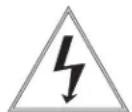
- Remove content from all boxes. Contents should include:
natural_image
White cylindrical object with black mounting holes and small circular features (no text or symbols visible)Main Housing Assembly
natural_image
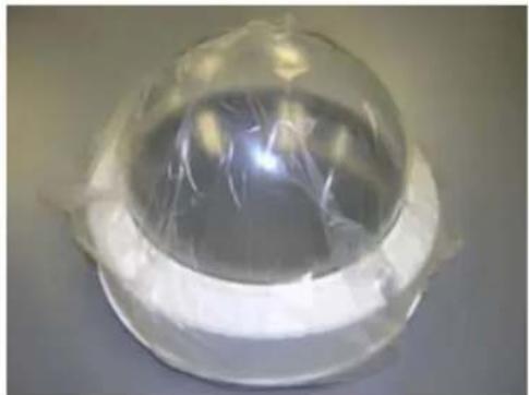
Close-up of a transparent dome-shaped object with a reflective interior, wrapped in plastic film (no text or symbols visible)Dome Assembly - Clear or Tinted
Do not remove the protective film until the product is assembled and installed.
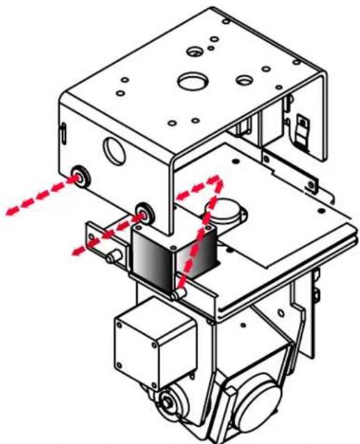
INSTALLATION OF PTZ CAMERA
Pan/Tilt unit is boxed separately and must be installed into the housing. Remove unit from box, slide the (2) pins on the pan/tilt base through the rubber grommets as shown below. Unit will not align unless base is fully pushed into place. Lower other end of base and secure with captive fastener.
natural_image
Technical line drawing of a mechanical assembly with mounting brackets and gears, showing red motion arrows (no text or symbols)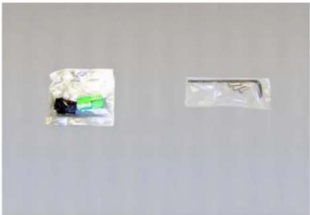
natural_image
Two plastic bags with different colors and shapes, one containing a green and black object, the other a white rectangular tag (no visible text or symbols)2 Packet Assemblies
WIRING INSTRUCTIONS (OUTSIDE OF HOUSING)
text_image
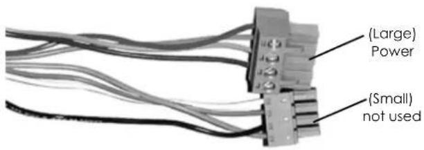
(Large) Power (Small) not usedWiring Color Code Power and Control Inputs (SM7CS-9)
| POWER | |||
| 1 | Camera Power (24 VAC) Red | 20 watts MAX | |
| 2 | Camera Power (24 VAC) Orange | ||
| 3 | Heater and Blower Power (24 VAC) Yellow | 52 watts | |
| 4 | Heater and Blower Power (24 VAC) Green | ||
(heater and blower not included on indoor unit)
Wiring Color Code Power and Control Inputs (SM7C12S-9)
| POWER | |||
| 1 | |||
| 2 | |||
| 3 | Heater and Blower Power (12 VDC) Red+ | 42 watts | |
| 4 | Heater and Blower Power (12 VDC) Black - | ||
(heater and blower not included on indoor unit)
| ALARM | ||
| 1 GND Red | ||
| 2 GND Violet | ||
| 3 ALARM OUT Gray | ||
| 4 ALARM IN White | ||
The unit is set up with (2) individual power inputs:
- Accessory Power (yellow and green wire)
- Camera Power (red and orange)
If you wish to provide a single power transformer it is recommended that:
- Be certain that you know the total power consumption of the housing Heater (50 watts) + Blower (2 watts) + camera pan/tilt (28 watts).
- Check the supplied wiring chart (see below) to be sure that you have the proper gauge wire for the distance that you intend to run your power wires.
24V AC Wiring Distances
The following are the recommended maximum distances for 24 VAC with a 10% voltage drop (10% is generally the maximum allowable voltage drop for AC powered devices).
Wire Gauge
| Total vA consumed | 22 | 20 | 18 | 16 | 14 | 12 | 10 |
| 5.5 | 250 | 400 | 600 | 960 | - | - | - |
| 10 | 120 | 180 | 300 | 480 | 800 | 1300 | - |
| 20 | 89 | 141 | 225 | 358 | 571 | 905 | 1440 |
| 30 | 65 | 90 | 130 | 225 | 350 | 525 | 830 |
| 40 | 44 | 70 | 112 | 179 | 285 | 452 | 720 |
| 50 | 35 | 56 | 90 | 143 | 228 | 362 | 576 |
| 60 | 29 | 47 | 75 | 119 | 190 | 301 | 480 |
| 70 | 25 | 40 | 64 | 102 | 163 | 258 | 411 |
| 80 | 31 | 34 | 55 | 85 | 140 | 215 | 340 |
Maximum distance from transformer to load
- Bring power to the 3 and 4 position of the power connector (yellow and green wire).
INSTALLING THE HOUSING ASSEMBLY:

Be sure the bracket is properly and securely mounted to a supporting structure capable of rigidly holding the weight of the entire unit.
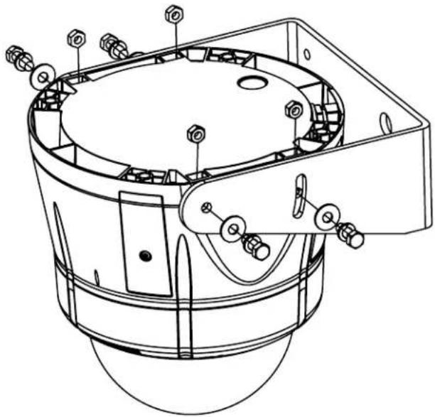
INSTALLING OPTIONAL WALL MOUNT
- Choose the desired location for installation and mark the drill holes using the template. Screw (2) bolts (not provided) about 34 of the way into the (2) top holes. Run approximately 8 of wiring out of the wall.
NOTE: Be sure the hardware and the mounting surface can support the weight of the wall mount bracket plus the weight of the housing and drive unit. The load will be subjected to vibration from the camera motor and wind.
-
The wall mount bracket provided with the SM7 includes a location for conduit entry. If you wish to install conduit to the bracket remove the conduit hole plug. Install fitting from below the wall mount and secure with conduit nut from inside the bracket.
-
Open the access door on the bottom of the wall mount by loosening the screw nearest the mounting plate.
natural_image
Technical line drawing of a mechanical assembly with bolted components and housing (no text or symbols)-
Attach the wires from the wall to the connector provided. using the wiring color code chart as a guide.
-
Once all wiring connections are made, place the wires inside the wall mount bracket and close the access door. Secure with the screw removed earlier.
CONNECTING THE TRIM RING ASSEMBLY TO THE HOUSING TOP:
-
Open the access door on the bottom of the wall mount by loosening the screw nearest the mounting plate.
-
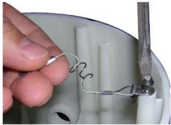
There is a safety lanyard that is attached to the inside of the dome assembly. Take the open end of the lanyard and loop it around the lanyard tab that is located inside the housing top.
natural_image
Close-up of a hand holding a wire spring attached to a small metallic component inside a white container (no text or symbols visible)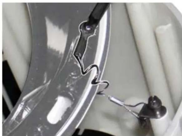
natural_image
Close-up of a metallic tool interacting with a transparent cylindrical object, possibly a lens or sensor (no visible text or symbols)- The safety lanyard is now attached to the trim ring.
CARE AND CLEANING OF DOMES:
All SM7 units include an optically clear polycarbonate dome. The dome is an optical device and should be handled with extreme care. Leave protective film on dome until product is fully assembled and installed. Even though the dome is virtually unbreakable, it can be easily scratched.
Clean only with a clean cotton cloth and warm water.
DO NOT use a strong solvent or cleanser!
SETTING PROTOCOL FOR THE UNIT
There are no user settings for protocol selection. The MR7CS-9 ^™ will respond to Pelco D, Pelco P, or Videolarm VL422 protocol automatically (1 start bit, 1 stop bit, 8 data bits, no parity).

text_image
Factory Settings DO NOT ADJUST Address Dip Switches PC Board located hereSETTING THE ADDRESS FOR THE UNIT
Each pan/tilt must have its own unique address. The factory default address is 001. To change this address use the 8 position dip switch located on the PC Board on the side of the pan/tilt (Figure 4), referring to the chart in the back of this manual. The address is set with the rocker style dip switches, which are non-volatile. The address cannot be changed unless the dip switches are moved, or unless the Remote Address feature in the VLC485 software is used.
OPTIONAL SETTINGS FOR THE MR7CS-9™
Protocols
The MR7CS-9™ supports VL422, Pelco P, and Pelco D protocols. The protocol is sensed automatically so there are no dip switches or adjustments for setting the protocol.
Day/Night Camera
When the light level is low, the camera will switch out the infrared filter and go to black and white mode. This feature can be permanently turned off, on, or set to automatic mode by using the menu in the On Screen Display.
Zones
There are 16 zones that may be programmed in the MR7CS-9™. Each zone may be set as a privacy zone with the video off. The zone title, if programmed and enabled, will be displayed regardless of whether the zone is programmed for privacy or not.
Presets
The MR7CS-9™ has 64 presets that can be used individually or as part of an auto tour. Preset 1 is the "home preset"; In addition, some presets have special functions as shown in the table below:
| PRESET NUMBER | COMMAND | FUNCTION |
| 66 | GO TO | Show this table |
| 70 | GO TO | Start Auto Tour |
| 80 | GO TO | Run Pattern |
| 80 | SET | Start Recording Pattern |
| 81 | SET | Stop Recording Pattern |
| 89 | GO TO | Put Camera Into Auto Iris Mode |
| 95 | GO TO | Display Main Menu |
Auto Tour
The auto tour function will automatically go, in sequence, to each preset that has been programmed. The dwell time for each preset can be set individually to be from 0 to 99 seconds.
NOTE: When the dwell time is set to "0" the preset will be replaced by the pattern (see below for setting). The pattern will execute, then auto tour will resume. More than one preset may be replaced by the pattern.
Pattern
A pattern is a programmed continuous path. The camera will follow this path repeatedly until the pattern is stopped. One pattern, with a maximum pattern time of 128 seconds, can be set.
MENU DRIVEN SETTINGS
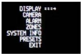
To enter the Main Menu, go to preset 95. The picture will disappear and the menu selections will appear on screen.
When you are in the Main Menu pan and tilt functions will not control the motion of the pan/tilt (except where noted). Instead, "Tilt Up" or "Tilt Down" will be used to navigate up or down along the main menu. "Pan Right" and "Pan Left" will be used to select between the main menu selection and the sub menu. The "Zoom In" and "Zoom Out" are used to turn the selected functions on or off.
text_image
DISPLAY ===→ CAMERA ALARM ZONES SYSTEM INFO PRESETS EXITDISPLAY - This controls the display of the compass heading and allows the user to calibrate the compass heading. PAN RIGHT to access the sub-menu. TILT DOWN to access each item. PAN LEFT to return to the main menu.
text_image
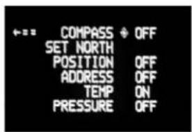
← = = COMPASS ◆ OFF SET NORTH POSITION OFF ADDRESS OFF TEMP ON PRESSURE OFFCOMPASS - The display show "COMPASS ON" or "COMPASS OFF". Press "zoom in" to turn the compass heading on and "zoom out" to turn the compass display off.
SET NORTH - Press "zoom in" button to set calibration. The display will show "OK".
POSITION - This displays the pan and tilt positions of the camera. Press "zoom in" to turn this on, "zoom out" to turn it off.
ADDRESS - This displays the camera address. Press "zoom in" to turn this on, "zoom out" to turn it off.
TEMP - This displays the temperature sensor data on the tilt board. Press "zoom in" to turn this on, "zoom out" to turn it off.
NOTE: This reading will be higher than the actual ambient temperature in the dome. This is for diagnostic use only.
PRESSURE - This displays the pressure sensor data for units equipped with a pressure sensor. Press "zoom in" to turn this on, "zoom out" to turn it off.
CAMERA - The "CAMERA" sub-menu is used to control several of the camera's parameters. PAN RIGHT to access the sub-menu. TILT DOWN to access each item.
NOTE: When this sub menu is accessed the camera picture will return to allow adjustments.
text_image
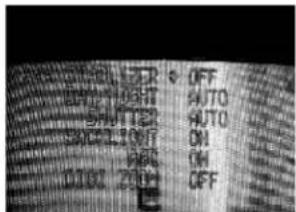
Cropped image of a printed document with fragmented text and symbols, possibly from a technical or legal document.STABILIZER - Stabilizer, where equipped, compensates for small movements or vibrations when the camera is "zoomed in". Press "zoom in" to turn this on, "zoom out" to turn it off.
DAY/NIGHT - This is used to control the low light mode of the camera. There are three choices:
AUTO - The camera will automatically switch into day/night mode for low light conditions.
DAY - The camera will be in the day mode continuously.
NIGHT - The camera will be in the night mode continuously. Press "zoom in" to cycle through the choices. P
SHUTTER - Selects between auto and manual shutter speeds. Press "zoom in" to cycle up through the selections, or "zoom out" to cycle down.
BACKLIGHT - Controls backlight compensation. Press "zoom in" to turn this on, "zoom out" to turn it off.
AGC - Selects automatic AGC or minimum AGC (0db). Press "zoom in" to turn this on, "zoom out" to turn it off.
DIGI ZOOM - Turns the digital zoom on and off. Press "zoom in" to turn this on, "zoom out" to turn it off.
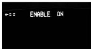
ALARM - To get to this section, tilt down from the CAMERA menu. This menu allows the user to control the operation of the alarm input. If the alarm is enabled, the camera will go to preset 1. Press "zoom in" to enable, press "zoom out" to disable.
text_image
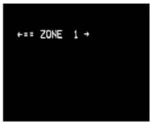
←== ENABLE ONZONES - Up to 16 zones may be selected, each zone has a number of parameters associated with it. Pan Right to access Zones. "ZONE 1" will display.
text_image
←== ZONE 1 →"Tilt up" or "Tilt down" to select the zone desired. Once the zone is selected, "Pan Right" to access the sub-menu.
text_image
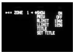
ZONE 1 ◆SHOW ON PRIU OFF RLIMIT 1342 LLIMIT 1258 TITLE SET TITLESHOW - Allows the title to be displayed. Press "zoom in" to turn this on, "zoom out" to turn it off.
PRIVATE - Determines if this will be a privacy zone. Press "zoom in" to turn this on, "zoom out" to turn it off.
RLIMIT - Sets the pan right limit for the zone. The current pan limit will be displayed. Press "zoom out", the picture will reappear and you will have pan control. Pan to the desired location. Press "zoom in" to select. The new pan limit will appear.
LLIMIT - Sets the pan left limit for the zone. The current pan limit will be displayed. Press "zoom out", the picture will reappear and you will have pan control. Pan to the desired location. Press "zoom in" to select. The new pan limit will appear.
NOTE: The picture will displayed whenever you are in RLIMIT or LLIMIT. When you toggle to any other sub-menu the picture will disappear.
TITLE - Displays the current title.
SET TITLE - This is used to set the title of the zone. The current zone title will be displayed at the bottom of the screen with at question mark (?) at the cursor position. Use pan right or left to change the cursor position. When the desired position has been selected, use tilt up and tilt down to select the character to be displayed. Press "zoom in" to set the title and exit the submenu. Pressing "zoom out" will restore the original title.
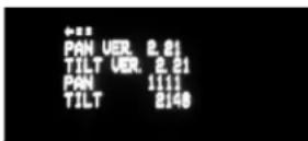
SYSTEM INFO - Displays the Pan Version, Tilt Version, Current Pan Position and Current Tilt Position.
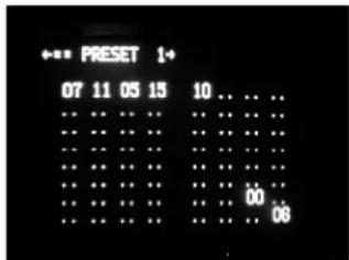
PRESETS - Allows the selection of the dwell times for each of the 64 presets. When this submenu is selected, the dwell time for each of the 64 presets is displayed.
NOTE: If a preset has not been saved, the dwell time for that preset will only be displayed as ".."
REMINDER: A dwell time of more than "0" can only be selected if a preset has been saved.
Press "tilt up" or "tilt down" to select the desired preset.
Pan right and the dwell time selection will appear. Press "tilt up" or "tilt down" to change the time.
Pan left to return to the Presets Selection sub-menu. Pan left again to return to the Main Menu.
PATTERN: The MR7CS-9 allows recording of one pattern of up to 128 seconds in length. This is a separate function from auto tour.
TO RECORD A PATTERN:
Set preset 80 to begin recording.
Record your pattern.
Set preset 81 to stop recording.
TO RUN THE PATTERN:
Go to preset 80.
TO STOP THE PATTERN:
Move the joystick.
TO MAKE THE PATTERN PART OF AUTO TOUR:
Set a preset or presets for which you want the pattern to run.
Go to the PRESETS section of the menu.
Go to the SET DWELL TIME function.
Set the dwell time for the desired presets to "0".
Exit the menu and go back to live video.
Press AUTO TOUR and the tour of each preset will begin. When the tour reaches the preset designated for a dwell time of "0" the pattern will run. The pattern can be set for as many presets as desired, however, only one pattern can be recorded.
EXIT - Pan left to exit the Main Menu.
text_image
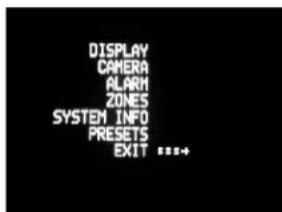
DISPLAY CAMERA ALARM ZONES SYSTEM INFO PRESETS EXIT ***+OTHER FEATURES:
Home Preset
Preset 1 is the "home preset". If this preset has been defined, then the VLTP385 will always go to this preset when the unit is powered up.
Remote Address
The Address of the unit can be set by a remote command. This "soft" address will be saved even if the unit loses power and will override the dip switch set address. The "soft" address can be cleared by a remote command and the address will be determined by the dip switch setting.
Program Download
There are two software programs in the standard unit. Each program can be updated via the command communication channel with a laptop or other computer system.
Error Messages
The "COMM ERROR" message will be displayed at the top of the screen whenever the MR7CS-9™ detects frame errors in the receive data, such as when the RXA and RXB wires are reversed when using RS485/422 or when the baud rate is incorrect.
The "CAMERA ERROR" message will be displayed at the top of the screen whenever there is an error in communicating with the camera.
DIPSWITCH SETTINGS:
Address Dip switch settings, refer to Table 1 on next page.
DIPSWITCH SETTINGS:
Address Dip switch settings, refer to Table 1.
Table 1: Pan/Tilt Address Dip Switch Settings
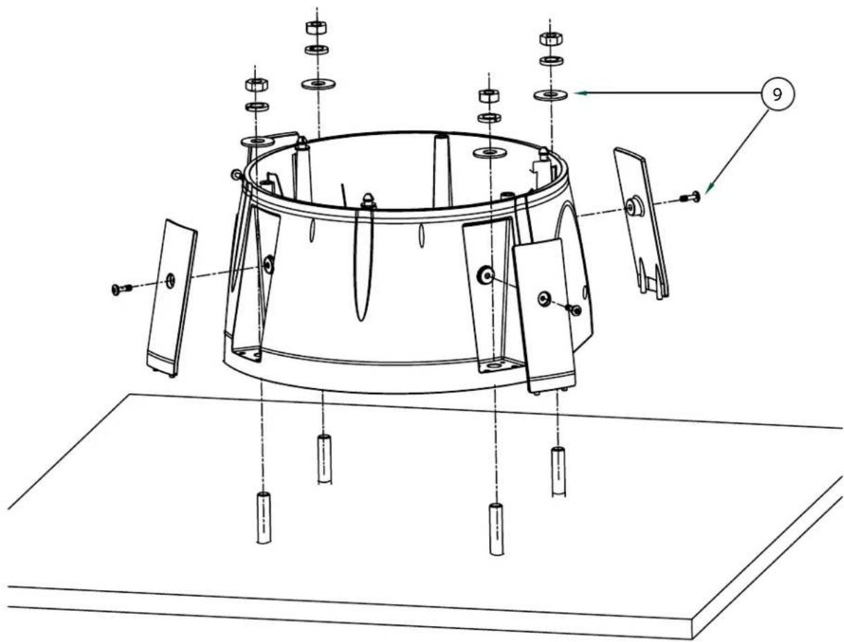
text_image
Technical diagram of a mechanical assembly with numbered components and labeled parts, including exploded view and component details.Exploded View for Replacement Parts (Surface Mount)
text_image
Technical diagram of a mechanical assembly with labeled components and alignment indicatorsReplacement Parts List
| Part Number Description | ||
| 1 | RPSM7501 DOME SEAL | |
| 2 | RPRH7502 LOWER TRIM RING | |
| 3 | RC7T TINTED REPLACEMENT CAPSULE | |
| RC7C CLEAR REPLACEMENT CAPSULE | ||
| 4 | RPRH7503 DOME CLAMPING BRACKET | |
| 5 | RPSM7511 HOUSING TOP | |
| 6 | RPSM7512 MOUNTING HOLE CLOSURE | |
| 7 | RPSM7513 CONDUIT HOLE CLOSURE | |
| 8 | RPSN7514 WALL MOUNT BRACKET (OPTIONAL) | |
| 9 | RPSM75040 HOUSING HARDWARE | |
| 10 | RPPKH2090 HOUSING HARDWARE PACKET A | |
| N/S | RPPKH2100 PACKET w/ ALLEN WRENCH and (3) SECURITY FASTENERS | |
| N/S | RPPKH2130 PACKET w/ 1/8 TAMPERPROOF KEY (SIDE PLATES) | |
Exploded View for Replacement Parts
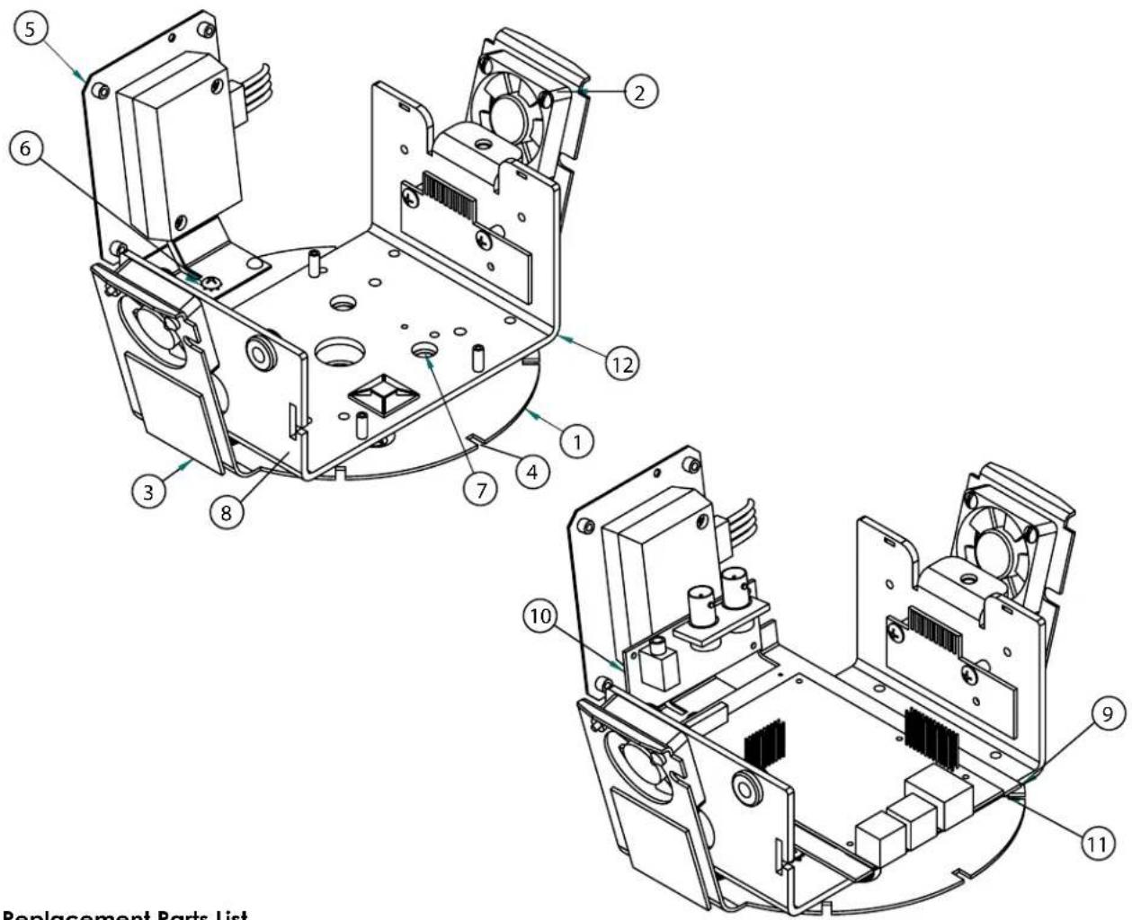
text_image
Replacement Parts ListReplacement Parts List
| Part No. Description | ||
| 1 RPFD060 Camera Bracket | ||
| 2 RPFD080 Blower (2) | ||
| 3 RPFD072 24VAC Heater (2) | ||
| 4 RPFD050 Connection PCB | ||
| 5 RP-TRAN03 24vac | to 12vdc Power Supply | |
| 6 RP40BRTRAN3 Power Supply with Bracket | ||
| 7 RP96VL2413 Pan Tilt Base Gasket | ||
| 8 RP40BRB38504 Pan/Tilt Base (Network) | ||
| 9 RPVL2982R0 IP Bracket | ||
| 10 RP76POF0605E IP Connection PCB | ||
| 11 RP70P1401S IP Main PCB | ||
Exploded View for Replacement Parts
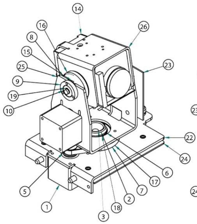
text_image
Technical diagram of a mechanical device with numbered components for identification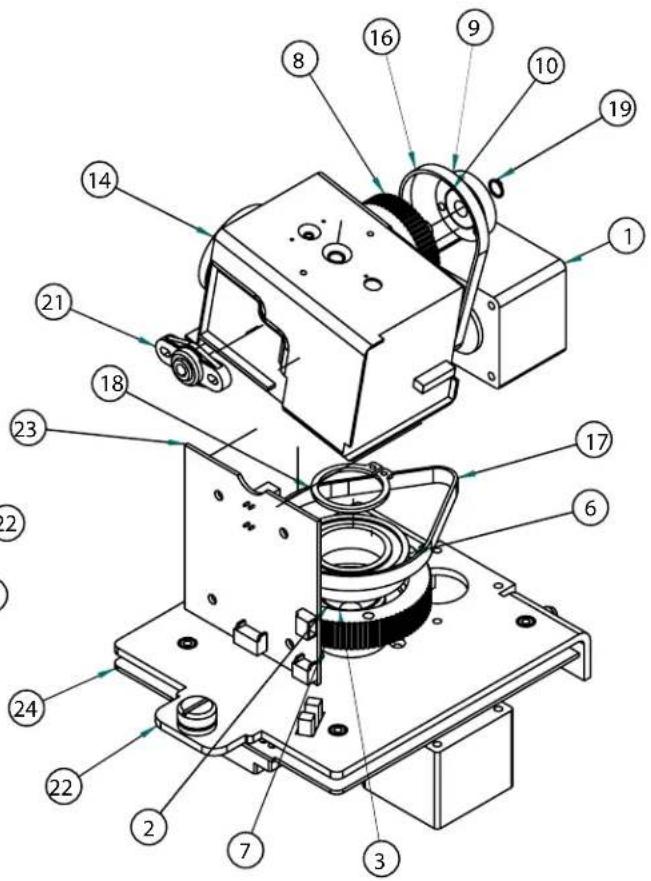
text_image
Technical diagram of a mechanical assembly with numbered components for identificationReplacement Parts List
| Part No. Description | |
| 1 RP6039mm1.8 Motor (2) | |
| 2 RPVL2314 Hub Bracket | |
| 3 RP40CASL385 Slip Ring Assembly (2) | |
| 5 RPVL2315 20T 80 Pitch Pulley (2) | |
| 6 RP605007 Bearing | |
| 7 RPVL2316 90T Pan Pulley | |
| 8 RPVL2318 60T Tilt Pulley | |
| 9 RPVL2320 Tilt Bearing Hub | |
| 10 RP605011 Bearing | |
| 14 RP73CAVKS454 23 X Zoom Camera | |
| 15 RP92WSFN11 Nylon Washer (2) | |
| 16 RP605009 Tilt Belt | |
| 17 RP605008 Pan belt | |
| 18 RP95FSSR06 Retaining ring (large) | |
| 19 RP95FSSR07 Retaining ring | |
| 21 RP605010 Tilt Bearing | |
| 22 RPVL2312R1 Quick Release Bracket | |
| 23 RP76V385T Tilt PCB | |
| 24 RP76V385P Main PCB | |
| 25* RPVL2317 Tilt Bracket | |
| 26* RPVL2321 Camera Bracket | |
Product Registration/Warranty
Thank you for choosing Videolarm. We value your patronage and are solely committed to providing you with only the highest quality products available with unmatched customer service levels that are second-to-none in the security industry.
Should a problem arise, rest assure that Videolarm stands behind its products by offering some of the most impressive warranty plans available: 3 Years on all Housings, Poles, Power Supples, and Accessories and 5 Years on all camera systems (SView, QView, Warriors), and InfraRed Illuminators.

Register Your Products

Option 1: Online Option 2: Mail-In
Take a few moments and validate your purchase with our Online Product Registration Form at www.videolarm.com/productregistration.jsp or complete and mail-in the bottom portion of this fl yer.
Register your recent Videolarm purchases and benefit from the following:
• Simple and Trouble-Free RMA process
- Added into customer database to receive product updates / news
- Eliminate the need to archive original purchase documents:
Receipts, Purchase Orders, etc...

Cut at the dotted Line
Place in envelope, affi x stamp and mail to: Videolarm ATTN: Warranty
2525 Park Central Ave.
Decatur, GA 30035
Main Contact Info
First Name:
Professional Title:
Address 1:
City: ____
Zip / Postal Code: ____ Phone Number:
Last Name:
Company:
Address 2:
/ Province/Country:
E-mail Address: ____
Product Information
Please Circle One: Business Personal
Name & Location of Company / Store where Purchased: ____
(City, State, Country)
Videolarm Product ID
Product Description
Serial # ____
(Available only for Camera Systems, IR Illuminators, Wireless Devices)
PO#